GOHFN WOLF P~. - ct.gov · GOHFN WOLF_P~._ ATTORNEYS AT LAW March 24, 2015 Attorney Melanie Bachman...
34
GOHFN WOLF _P~._ ATTORNEYS AT LAW March 24, 2015 Attorney Melanie Bachman Acting Executive Director Connecticut Siting Council Ten Franklin Square New Britain, CT 06051 JULIE D. KOHLER PLEASE REPLY TO: BfIC~g2p01~ WRITER~s ~iREcr ~iA~: (203) 337-4157 E-Mail Address: [email protected] Re: Notice of Exempt Modification Robert J. Kaufman, Seven T LLC/T-Mobile co-location Site ID CT11923C 7 West View Drive, Danbury Dear Attorney Bachman: This office represents T -Mobile Northeast LLC ("T -Mobile") and has been retained to file exempt modification filings with the Connecticut Siting Council on its behalf. In this case, Robert J. Kaufman, Seven T, LLC owns the existing lattice telecommunications tower and related facility at 7 West View Drive, Danbury Connecticut (coordinates 41.396/ -73.42380). T -Mobile intends to add three (3) antennas and related equipment at this existing telecommunications facility in Danbury ("Danbury Facility"). Please accept this letter as notification, pursuant to R.C.S.A. § 16-50j-73, of construction which constitutes an exempt modification pursuant to R.C.S.A. § 16 -50j -72(b)(2). In accordance with R.C.S.A. § 16-50j-73, a copy of this letter is being sent to the Mayor, Mark D. Boughton. Robert J. Kaufman, Seven T, LLC is also the property owner. The existing Danbury Facility consists of a 100 foot tall lattice structure.' T -Mobile plans to add three (3) antennas and three (3) RRUs (remote radio units) at a centerline of 50 feet. (See the plans dated March 10, 2015 attached hereto as Exhibit A). T -Mobile will also use the spare fiber cable for the proposed antennas. The existing Facility is structurally capable of supporting T -Mobile's proposed modifications, as indicated in the structural analysis dated March 6, 2015 and attached hereto as Exhibit B. ~ While the online docket for the Connecticut Siting Council does not provide a docket or petition number for the approval of this structure, it does reference this structure in connection with notices of intent captioned EM-T- MOBILE-034-130726 and EM-T -MOBILE -034-090409. ILLS BROAD STREET ISS DEER HILL AVENUE 32O POST ROAD WEST 6S~ ORANGE CENTER ROAD P.O. BOX 1821 DANBURY CT 06810 WESTPORT, C'i' 06880 ORANGE, CI' 06477 BxincEroxT, CT 06601-1821 T'sL: (203) 7922771 Tai: (203) 222-1034 '1~L: (203) 298-0066 fir,: (203) 3b8-02ll Fax: (203) 791-8149 Fax: (203) 227-1373 Fnx: (203) 298-4068 Fax: (203) 3949901
Transcript of GOHFN WOLF P~. - ct.gov · GOHFN WOLF_P~._ ATTORNEYS AT LAW March 24, 2015 Attorney Melanie Bachman...

GOHFNWOLF_P~._ATTORNEYS AT LAW
March 24, 2015
Attorney Melanie BachmanActing Executive DirectorConnecticut Siting CouncilTen Franklin SquareNew Britain, CT 06051
JULIE D. KOHLER
PLEASE REPLY TO: BfIC~g2p01~
WRITER~s ~iREcr ~iA~: (203) 337-4157E-Mail Address: [email protected]
Re: Notice of Exempt ModificationRobert J. Kaufman, Seven T LLC/T-Mobile co-locationSite ID CT11923C7 West View Drive, Danbury
Dear Attorney Bachman:
This office represents T-Mobile Northeast LLC ("T-Mobile") and has been retained tofile exempt modification filings with the Connecticut Siting Council on its behalf.
In this case, Robert J. Kaufman, Seven T, LLC owns the existing latticetelecommunications tower and related facility at 7 West View Drive, Danbury Connecticut(coordinates 41.396/ -73.42380). T-Mobile intends to add three (3) antennas and relatedequipment at this existing telecommunications facility in Danbury ("Danbury Facility"). Pleaseaccept this letter as notification, pursuant to R.C.S.A. § 16-50j-73, of construction whichconstitutes an exempt modification pursuant to R.C.S.A. § 16-50j-72(b)(2). In accordance withR.C.S.A. § 16-50j-73, a copy of this letter is being sent to the Mayor, Mark D. Boughton.Robert J. Kaufman, Seven T, LLC is also the property owner.
The existing Danbury Facility consists of a 100 foot tall lattice structure.' T-Mobileplans to add three (3) antennas and three (3) RRUs (remote radio units) at a centerline of 50feet. (See the plans dated March 10, 2015 attached hereto as Exhibit A). T-Mobile will alsouse the spare fiber cable for the proposed antennas. The existing Facility is structurallycapable of supporting T-Mobile's proposed modifications, as indicated in the structuralanalysis dated March 6, 2015 and attached hereto as Exhibit B.
~ While the online docket for the Connecticut Siting Council does not provide a docket or petition number for theapproval of this structure, it does reference this structure in connection with notices of intent captioned EM-T-MOBILE-034-130726 and EM-T-MOBILE-034-090409.
ILLS BROAD STREET ISS DEER HILL AVENUE 32O POST ROAD WEST 6S~ ORANGE CENTER ROAD
P.O. BOX 1821 DANBURY CT 06810 WESTPORT, C'i' 06880 ORANGE, CI' 06477BxincEroxT, CT 06601-1821 T'sL: (203) 7922771 Tai: (203) 222-1034 '1~L: (203) 298-0066fir,: (203) 3b8-02ll Fax: (203) 791-8149 Fax: (203) 227-1373 Fnx: (203) 298-4068Fax: (203) 3949901

COHFNWOLF~FC.~gTTONNEI'S AT LAW
March 24, 2015Site ID CT11923CPage 2
The planned modifications to the Danbury Facility fall squarely within those activitiesexplicitly provided for in R.C.S.A. § 16-50j-72(b)(2).
1 . The proposed modification will not increase the height of the tower. T-Mobile'sadditional antennas and equipment will be installed at the 50 foot level. The enclosed towerdrawing confirms that the proposed modification will not increase the height of the tower.
2 . T-Mobile does not propose any changes to the compound area so themodifications will not require an extension of the site boundaries. (See Sheet A-1
3 . The proposed modification to the Facility will not increase the noise levels at theexisting facility by six decibels or more.
4 . The operation of the replacement antennas will not increase the total radiofrequency (RF) power density, measured at the base of the tower, to a level at or above theapplicable standard. According to a Radio Frequency Emissions Analysis Report prepared byEBI dated March 18, 2015 T-Mobile's operations would add 62.34% of the FCC Standard.Therefore, the calculated "worst case" power density for the planned combined operation atthe site including all of the proposed antennas would be 65.94% of the FCC Standard ascalculated for a mixed frequency site as evidenced by the engineering exhibit attached heretoas Exhibit C.
For the foregoing reasons, T-Mobile respectfully submits that the proposed replacementantennas and equipment at the Danbury Facility constitutes an exempt modification underR.C.S.A. § 16-50j-72(b)(2). Upon acknowledgement by the Council of this proposed exemptmodification, T-Mobile shall commence construction approximately sixty days from the date ofthe Council's notice of acknowledgement.
Sincerely,
V~~'ul e D. Kohler, Esq.
cc: City of Danbury, Mayor Mark D. BoughtonRobert J. Kaufman Seven T, LLCElizabeth Jamieson, Transcend Wireless

SITE NAME: CT923/W. VIEW DR GT
r
7 WEST VIEW DRIVE,
DANBURY, CT Ofi810
SITE NUMBER: CT11923C
L700 - 7
02CU CONFIGURATION
GENERAL NOTES
1. THIS DOCUMENT IS T
HE CREATION, DESIGN. P
ROPERN AND COPYRIGHTED WORK OF
T—MOBILE. ANY DUPLICATION
OR USE WITHOUT EXPRESS WRITTEN
CONSENT IS
STRICTLYPROHIBITED. DUPLICATION
AND USE BY GOVERNMENT AGENCIES FOR THE PURPOSES OF
CONDUCTING THEIR
LAWFULLY AUTHORIZED REGULATORY AND ADMINISTRATIVE
FUNCTfONS IS
SPECIFICALLY ALLOWED.
2. THE FACILITY fS
AN UNMANNED PRIVATE A
ND SECURED EQUIPMENT INSTALLATION.
IT IS
ONLY
ACCESSED BY TR4INED
TECHNICIANS FOR PERIODIC
ROUTINE MAINTENANCE AND THEREFORE
DOES NOT REQUIRE ANY WATER OR SANITARY SEWER SERVICE.
THE FACILITY
IS NOT
GOVERNED BY REGULATIONS REQUIRING
PUBLJC ACCESS PER ADA REQUIREMENTS_
3. CONTRACTOR SHALL VERIFY
ALL PL4NS AND EXISTING
DIMENSIONS AND CONDITIONS ON THE
JOB SITE
AND SHALL IMMEDIATELY
NOTIFY THE T—MOBILE NORTHEAST, LLC
REPRESENTATIVE
IN WRITING
OF DISCREPANCIES BEFORE PROCEEDING WITH
THE WORK OR BE RESPONSIBLE
FOR SAME.
SPECIAL STRUCTURAL NOTES
1. STRUCTURAL DESIGNS AND DETAILS
FOR ANTENNA MOUNTS COMPLETED BY HUDSON DESIGN
ON BEHALF OF T—A~OBILE
ARE INCLUSIVE
OF THE ENTIRE
ANTENNA SUPPORT STRUCTURE
(GLOBAL STRUCTURAL
STABILITY ANALYSIS
BY OTHERS),
EXISTING TOWER
PLATFORM,
DCISTING ANTENNA MOUNTS AND ALL OTHER ASPECTS OF THE STRUCTURE THAT WILL
SUPPORT THE T—MOBILE MODERNIZATION EQUIPMENT DEPLOYMENT AS DEPICTED HEREIN.
2. HUDSON DESIGN ASSUMES THAT THE TOWER IS
PROPERLY CONSTRUCTED AND MAINTAINED.
ALL SfRUCTllRAL
MEMBERS ANQ THEIR
CONNECTION ARE ASSUMED TO BE
IN GOOD
CONDf110N AND ARE FREE FROM DEFECTS WITH
NO DETERIORATION
TO RS A~EMBER
cnaAcmEs
APPROVALS
T
_ --
_ __
_ _ _----- —
_ _
--
-- --- - -
-
- _PROJECT MANAGER
DATE
CONSTRUCTION
DATE
RF ENGINEERING
DATE
~. -- -
--
ZONING /SITE ACQ.
DATE
OPERAi70N5
DATE
TOWER OWNER
DATE
-~ ~.
~.~ ~°
`~` ~
~(mrww j~we a.
N Wt~
q~9
waoa; ,~~r a.~ -
~~w
e ~,
~m~Yy -7
~
;,+*m,.
4
b
Rj
~y~o~e
PROJECT
SITE
~,=
std~H r~odcea~~a ,smog
r~~f~N4~mlmml
_ S
of Mma Vchahs
`.~.~..
s,
Shenaeo~raS ti
«:
Mai [aunvf
Meuew scrmd
~n~;.
~
Gcw~lc
__
BALL
BEFORE YOU DIG
CALL TOLL FREE 800-922-4455
OR CALL 81 1
UNDERGROUND SERVICE ALERT
T-MOBILE TECHNICIAN SITE SAFETY NOTES
LOCATION SPECIAL RESTRICTIONS
SECTOR A:
ACCESS NOT PERMITTED
SECTOR B:
ACCESS NOT PERMITTED
SECTOR C:
ACCESS NOT PERMITTED
GPS/LMU:
UNRESTRICTED
RADIO CABINETS:
UNRESTRICTED
PPC DISCONNECT:
UNRESTRICTED
MAIN CIRCUIT D
/C:
UNRESTRICTED
NIU/T DEMARC:
UNRESTRICTED
OTHER/SPECIAL:
NONE
PROJECT INFORMATION
SCOPE OF WORK:
UNMANNED TELECOMMUNICATIONS FACILITY T
—MOBILE
EQUIPMENT MODERNIZATION
ZONING JURISDICTION:
BASED ON INFORMATION
PROVIDES BY T—MOBILE, THIS
TELECOMMUNICATIONS EQUIPMENT DEPLOYMENT IS
AN
ELIGIBLE FACILITY
UNDER THE TAX RELIEF A
CT OF 2012,
47 USC 1455(A), A
ND IS S
UBJECT TO AN EXPEDITED
ELIGIBLE FACILITIES
REQUEST/REVIEW AND ZONING
PRE—EMPTION FOR LOCAL DISCREf10NARY PERMITS
(VARIANCE, SPECIAL
PERMIT, SITE PLAN REVIEW).
SITE ADDRESS:
7 WEST VIEW
DRIVEDANBURY, CT 06810
LATITUDE: 41' 00' 38.81" N
LONGITUDE:
73' 39' 31.50" W
JURISDICTION: NATIONAL, STATE &
LOCAL CODES OR ORDINANCES
CURRENT USE:
TELECOMMUNICATIONS FACILITY
PROPOSED USE:
TELECOMMUNICATIONS FACILJN
DRAWING INDEX
REV
T-1 TITLE SHEET
1
GN-1 GENERAL NOTES
1
A-1 SITE PLAN &ELEVATION
1
A-2
ANTENNA PLAN AND MOUNTING DETAILS
1
G-1 GROUNDING DETAILS
1
T-MOBILE NORTHEAST L.LC
35 GRIFFlN
ROAd SOUTH
BLOOMF1EtD, CT O6DG2
OFFECf: ($50) 648-1176
Transcend Wire%ss
IRL.~CB~+J N'~4'etE15i0CU1GTRNI A~YF
1tt-~_<;~G744i~#5hH'fNAtl. !11 G
+1Y
=rV::{Y,e3~i8+87?d
Huc~sar~~~
oai~gn Grouu ~
iwoascamm~?
mane c :a r~~r, e ;wrt .;ao
ra: nxp ssr.sss~H.ANq(iYEB, M
Apt34$
fA%; N7~~J3+,Sfiey
",1 ,\1ti14~i1 t I I I Ul41flilfj
`~~~~~~~~~ ~,~~El~~~~hii
Yet ~ ri
y .
~.
r•, c_
~
~b`f~~RC3IYALS
COldS1RUCTION t),4TE
RF ENGINEERING 17ATE
20NING~SfTE ACS. pATE
OPERATIONS []ATE
TONER QWHER
DATE
PROJECT ND:
CT11923C
DRAWN BY:
MH
CHEGiCED BY:
DR
1 03/t0/t5 ISSIlEA
FOR REVIEW
D 43/47/75 ISStPEO
F'Ofi REVIEW
SITE NUMBER: GT11923C
51TE NAME:
CTS231W. VIEW DR GT
7 WE5T VIEW
RRtVE
~AiJBURY, CT 06810
SHEET TITLE
TITLE SHEET
SHEET NUMBER
T-1

GROUNDING NOTES
THE SUBCONTRACTOR SHALL REVfEW
AND INSPECT
THE
EXISTING FACILITY
GROUNDING SYSTEM AND LIGHTNING
PROTECTION SYSTE~1 (
AS DESIGNED
AND INSTALLED) F
OR
STRICT COMPLIANCE WITH
THE NEC (AS ADOPTED BY THE
AHJ), THE SITE-SPEC{FIC (
UL, LPI, O
R NFPA) LIGkTING
PROTECTION CODE, AND GENERAL COMPLIANCE WITH
TELCORDIA AND TIA
GROUNDING STANDARDS. THE
SUBCONTRACTOR SHALL REPORT ANY VIOLATIONS
OR
ADVERSE FINDINGS
TO THE CONTRACTOR FOR RESOLUTION.
2. AlL GROUND ELECTRODE SYSTEMS (INCLUDING
TELECOMMUNICATION, RAD10, LIGHTNING PROTECTION, A
ND
AC POWER GES'S) S
HALL BE BONDED TaGETHER, AT
OR
BELOW GRADE, BY TWO OR MORE COPPER BONDING
CONDUCTORS IN
ACCORDANCE WITH
THE NEC.
3. THE SUBCONTRACTOR SHALL PERFORM IEEE
FALL-OF-POTENTIAL
RESISTANCE TO EARTH TESTING (
PER IEEE
1100 AND 81) FOR NEW GROUND ELECTRODE SYSTEMS. THE
SUBCONTRACTOR SHALL FURNISH AND INSTALL
SUPPLEMENTAL GROUND ELECTRODES AS NEEDED TO
ACHIEVE A TEST
RESULT OF 5 OHMS OR LESS.
4. METAL RACEWAY SHALL NOT BE USED AS THE NEC
REOUIREO EQUIPMENT GROUNO CONDUCTOR. STRANDED
COPPER CONDUCTORS WITH
GREEN INSULATION, SIZED
IN
ACCORDANCE WITH
THE NEC, SHALL BE FURNISHED AND
INSTALLED WITH T
HE POWER CIRCUITS T
O BTS EQUIPMENT.
5, EACH BTS CABINET
FRAME SHALL BE DIRECTLY
CONNECTED TO THE MASTER GROUND BAR WITH
GREEN
INSULATED SUPPLEMENTAL EQUIPMENT GROUND WIRES, 6
AWG STRANDED COPPER OR LARGER FOR INDOOR BTS 2 AWG
STRANDED COPPER FOR OUTDOOR BiS,
b. EXOTHERMIC WELDS SHALL BE USED FOR ALL
GROUNDING
CONNECTIONS BELOW GRADE.
7, APPROVED ANTIOXIDANT
COATWGS (I,E., C
ONDUCTIVE GEL
OR PASTE) S
HALL BE
USED ON ALL
COMPRESSION AND
BOLTED GROUND CONNECTIONS.
8. ICE BRIDGE
BONDING CONDUCTORS SHALL BE
EXOTHERMICALLY BONDED OR BOLTED TO THE BRIDGE A
ND
THE TOWER GROUND BAR.
9. ALUMINUM CONDUCTOR OR COPPER CLAD STEEL
CONDUCTOR SHALL NOT BE USED FOR GROUNDING
CONNECTIONS.
10. MISCELLANEOUS
ELECTRICAL AND NON-ELECTRICAL
METAL BOXES, FRAMES AND SUPPORTS SHALL BE BONDED
70 THE GROUND RING, IN
ACCORDANCE WITH
THE NEC.
11. METAL CONDUIT
SHALL BE MADE ELECTRICALLY
CONTINUOUS WITH
LISTED BONDING FITTINGS
OR BY
BONDING ACROSS THE DISCONTINUI71` WITH 6
AWS COPPER
WIRE UL APPROVED GROUNDING 11'PE
CONDUIT CLAMPS.
12. ALL NEW STRUCTURES WITH
A FOUNDATION AND/OR FOOTING
HAVING 20 FT.
OR MORE OF 1/2 IN.
OR GREATER
ELECTRICALLY CONDUCTIVE REINFORCING STEEL MUST HAVE IT
BONDED TO THE GROUND RING USING AN EXOTHERMIC WELD
CONNECTION USING ~2 AWG SOLID BARE TINNED COPPER
GROUND WIRE, P
ER NEC 250.50
GENERAL NOTES
1. FOR THE PURPOSE OF CONSTRUCTION DRAWING, THE FOLLOWING
DEFINITIONS SHALL APPLY:
CONTRACTOR - TRANSCEND WIRELESS
SUBCONTRACTOR -GENERAL CONTRACTOR (CONSTRUCTION)
OWNER - T-MOBILE
2.
PRIOR TO THE SUBMISSION OF BIDS, T
HE BIDDING
SUBCONTRACTOR SHALL
VISIT THE CELL SITE
TO FAMILIARIZE
WITH THE EXISTING
CONDITIONS AND TO
CONFIRM THAT THE WORK CAN BE ACCOMPLISHED AS SHOWN ON THE
CONSTRUCTION DRAWINGS. ANY DISCREPANCY FOUND SHALL BE BROUGHT TO
THE ATTENTION OF CONTRACTOR.
3. ALL MATERIALS FURNISHED AND INSTALLED SHALL BE IN
STRICTACCORDANCE WITH
ALL APPLICABLE CODES, REGULATIONS, AND ORDfNANCES.
SUBCONTRACTOR SHALL ISSUE ALL APPROPRIATE NOTICES AND COMPLY WITH
ALL LAWS, ORDINANCES, RULES, REGULATIONS, AND LAWFUL ORDERS OF ANY
PUBLIC AUTHORITY REGARDING THE PERFORMANCE OF THE WORK. ALL WORK
CARRIED OUT SHALL COMPLY WITH
ALL APPLICABLE MUNICIPAL AND UTILITY
COMPANY SPECIFICATIONS AND LOCAL JURISDICTIONAL CODES, ORDINANCES AND
APPLICABLE REGULATIONS.
4. DRAWINGS PROVIDED HERE ARE NOT TO BE SCALED AND ARE INTENDED
TO SHOW OUTLINE ONLY.
5. UNLESS NOTED OTHERWISE, THE WORK SHALL INCLUDE FURNISHING
MATERIALS, EQUIPMENT, APPURTENANCES, AND LABOR NECESSARY TO COMPLETE
ALL INSTALLATIONS AS INDICATED ON THE DRAWINGS.
6.
"KITTING LIST" S
UPPLIED WITH THE BID
PACKAGE IDENTIFIES
ITEMS THAT
WILL BE SUPPLIED BY CONTRACTOR. ITEMS NOT INCLUDED IN
THE BILL
OF
MATERIALS AND KITTING
LIST SHALL BE SUPPLIED BY THE SUBCONTRACTOR.
7. THE SUBCONTRACTOR SHALL INSTALL
ALL EQUIPMENT AND MATERIALS IN
ACCORDANCE WITH
MANUFACTURER'S RECOMMENDATIONS UNLESS SPECIFICALLY
STATED OTHERWISE.
8.
IF THE SPECIFIED EQUIPMENT CANNOT BE INSTALLED AS SHOWN ON THESE
DRAWINGS, THE SUBCONTRACTOR SHALL PROPOSE AN ALTERNATIVE INSTALLATION
SPACE FOR APPROVAL BY THE CONTRACTOR.
9. SUBCONTRACTOR SHALL DETERMINE ACTUAL ROUTING OF CONDUIT, POWER
AND T1
CABLES, GROUNDING CABLES AS SHOWN ON THE POWER, GROUNDING
AND TELCO PLAN DRAWING. SUBCONTRACTOR SHALL UTILIZE
EXISTING TRAYS
ANO/OR SHALL AOD NEW TRAYS AS NECESSARY. SUBCONTRACTOR SHALL
CONFIRM THE ACTUAL ROUTING WfTH
THE CONTRACTOR.
10. THE SUBCONTRACTOR SHALL PROTECT EXISTING
IMPROVEMENTS,
PAVEMENTS, CURBS, LANDSCAPING AND STRUCTURES. ANY DAMAGED PART
SHALL BE REPAIRED AT
SUBCONTRACTOR'S EXPENSE TO THE SATISFACTION
OF
OWNER.
11. SUBCONTRACTOR SHALL LEGALLY AND PROPERLY DISPOSE OF ALL SCRAP
MATERIALS SUCH AS COAXIAL CABLES AND OTHER ITEMS REMOVED FROM THE
EXISTING FACILITY.
ANTENNAS REMOVED SHALL BE RETURNED TO THE OWNER'S
DESIGNATED LOCATION,
12. SUBCONTRACTOR SHALL LEAVE PREMISES IN
CLEAN CONDITION,
13. ALL CONCRETE REPAIR WORK SHALL BE DONE IN
ACCORDANCE WITH
AMERICAN CONCRETE INSTITUTE (ACI) 3
01.
14. ANY NEW CONCRETE NEEDED FOR THE CONSTRUCTION SHALL BE
AIR -ENTRAINED AND SHALL HAVE 4000 PSI
STRENGTH AT 28 DAYS.
ALL
CONCRETE WORK SHALL BE DONE IN
ACCORDANCE WITH
ACI 318 CODE
REQUIREMENTS.
15. ALL STRUCTURAL STEEL WORK SHALL BE DETAILED, F
ABRICATED AND ERECTED
IN ACCORDANCE WITH AISC
SPECIFICATIONS. ALL STRUCTURAL STEEL SHALL BE
ASTM A36 (Fy = 36 ksi)
UNLESS OTHERWISE NOTED.
PIPES SHALL BE ASTM A53
TYPE E (Fy = 36 ksi).
ALL STEEL EXPOSED TO WEATHER SHALL BE HOT DIPPED
GALVANIZED. TOUCHUP ALL SCRATCHES AND OTHER MARKS IN
THE FIELD
AFTER
STEEL IS
ERECTED USING A COMPATIBLE ZINC RICH PAINT.
16. CONSTRUCTION SHALL COMPLY WITH
UMTS SPECIFICATIONS AND "GENERAL
CONSTRUCTION SERVICES FOR CONSTRUCTION OF T-MOBILE SITES."
17. SUBCONTRACTOR SHALL VERIFY
ALL EXISTING
DIMENSIONS AND CONDITIONS
PRIOR TO COMMENCING ANY WORK. ALL DIMENSIONS OF EXISTING
CONSTRUCTION
SHOWN ON THE DRAWINGS MUST BE VERIFIED.
SUBCONTRACTOR SHALL NOTIFY
THE CONTRACTOR OF ANY DISCREPANCIES PRIOR TO ORDERING MATERIAL OR
PROCEEDING WITH
CONSTRUCTION.
18. THE EXISTING
CELL SITE
IS IN
FULL COMMERCIAL. OPERATION. ANY
CONSTRUCTION WORK BY SUBCONTRACTOR SHALL NOT DISRUPT THE EXISTING
NORMAL OPERATION. ANY WORK ON EXISTING
EQUIPMENT MUST BE COORDINATED
WITH CONTRACTOR. ALSO, WORK SHOULD BE SCHEDULED FOR AN APPROPRIATE
MAINTENANCE WINDOW USUALLY IN
LOW TRAFFIC PERIODS AFTER MIDNIGHT.
19. SINCE THE CELL SITE
IS ACTIVE, A
LL SAFETY PRECAUTIONS MUST BE TAKEN
WHEN WORKING AROUND HIGH LEVELS OF ELECTROMAGNETIC RADIATION.
EQUIPMENT SHOULD BE SHUTDOWN PRIOR TO PERFORMING ANY WORK THAT
COULD EXPOSE THE WORKERS TO DANGER. PERSONAL Rf E
XPOSURE MONITORS
ARE ADVISED TO BE WORN TO ALERT OF ANY DANGEROUS EXPOSURE LEVELS.
20. APPLICABLE BUILDING CODES:
SUBCONTRACTORS WORK SHALL COMPLY WITH ALL APPLICABLE NATIONAL, STATE,
AND LOCAL CODES RS ADOPTED BY THE LOCAL AUTHORITY HAVING JURISDICTION
(AHJ) FOR THE LOCATION. THE EDITION
OF THE AHJ ADOPTED CODES AND
STANDARDS iN
EFFECT ON THE DATE OF CONTRACT AWARD SHALL GOVERN THE
DESIGN.BUI~DiNG CODE: IBC
2003 W/ 2005 CT SUPPLEMENT + 2009 AMENDMENT
ELECTRICAL CODE: REFER TO ELECTRICAL DRAWINGS
LIGHTENING CODE: REFER TO ELECTRICAL DRAWINGS
SUBCONTRACTOR'S WORK SHALL COMPLY WITH
THE LATEST EDITION
OF THE
FOLLOWING STANDARDS:
AMERICAN CONCRETE INSTITUTE (ACI) 3
18; BUILDING CODE
REQUIREMENTS FOR STRUCTURAL CONCRETE;
AMERICAN INSTITUTE
OF STEEL CONSTRUCTION (AISC)
MANUAL OF STEEL CONSTRUCTION, ASD, 14TH EDITION;
TELECOMMUNICATIONS INDUSTRY ASSOCIATION (TIA) 2
22-F,
STRUCTURAL STANDARDS FOR STEEL
ANTENNA TOWER AND ANTENNA SUPPORTING STRUCTURES; REFER
TO ELECTRICAL DRAWINGS FOR SPECIFIC
ELECTRICAL STANDARDS.
FOR ANY CONFLICTS BETWEEN SECTIONS 6F LISTED
CODES AND STANDARDS
REGARDING MATERIAL,
METHODS OF CONSTRUCTION, OR OTHER REQUIREMENTS,
THE MOST RESTRICTIVE
REQUIREMENT SHALL GOVERN. WHERE THERE IS
CONFLICT
BETWEEN A GENERAL REQUIREMENT AND A SPECIFIC REQUIREMENT, THE SPECIFIC
REQUIREMENT SHALL GOVERN.
ABBREVIATIONS
AGL
ABOVE GRADE LEVEL
G.C. GENERAL CONTRACTOR
RF
RADIO FREQUENCY
AWG
AMERICAN WIRE GAUGE
MGB
MASTER GROUND BUS
BCW
BARE COPPER WIRE
MIN MINIMUM
TBD
TO BE DETERMINED
BTS
BASE TRANSCEIVER
STATION PROPOSED
NEW
T8R
TO BE REMOVED
EXISTING EXISTING
N.T.S. NOT TO SCALE
TBRR
TO BE REMOVED
EG
EQUIPMENT GROUND
REF
REFERENCE
AND REPLACED
EGR
EQUIPMENT GROUND RING
REO
REQUIRED
TYP
TYPICAL
T-MOBILE NORTHEAST LLC
35 GRIFFIN
ROAD 50UTH
BLOOMFIELD, CT 06002
OFFICE: (860) 648-1 1 1
6
Transcend Wig
ss
mnr+sc~+o w~R¢~a101NDUS7RIALAVE
Tfl:~201J 664~OD55MANWAH, N107/30
FAX:(~1~684~W66
Hudson4!
Design Group~.~
~6000SGOOD SfREEf
BUILDING 20 NORIFI,SURE 3090 la; ~978~557~553
N. ANDOVER, MA 01845
FA%: (9781336u5A6
U~̀\ 1~4~tIlll I I I IUt7lll//~j~i
.,,°,,,(~~~'oF CaN,yF °~%''',j,,
c ~
~
~ z
~~
'
~
~ ~NS~~.'. ~~`a\tiq
r~'19'(~1Y` LS
CONSTRUCTION DATE
RF ENGINEERING GATE
ZONING/SITE ACQ.
DATE
OPERATIONS DATE
TOWER pWNER
DATE
PROJECT N0:
CT11923C
DRAWN @Y:
MH
CHECKED 8Y:
DR
1 03/10/15 ISSUED FOR REVIEW
0 03/02/15 ISSUED FOR REVIEW
SITE NUMBER: CT11923C
SITE NAME:
CT923/W. VIEW DR GT
7 WEST VIEW
DRIVE
DANBURY, CT 06810
SHEET TITLE
GENERAL NOTES
SHEET NUMBER
GN-1

.~_ ~TAP
OF TOWER EXTENSION
STRUCTURAL NOTE:
V ELEV.
135'-0"± (AGL)
STRUCTURAL INFORMATION
TAKEN FROM
STRUCTURAL ANALYSIS
PERFORMED BY HUDSON DESIGN GROUP LLC
DATED: MARCH 6, 2
015
EXISTING WINDOW
(~'P )f EXISTING
TELCO
J BOARD
EXISTING STAIRS
1 ~
r- EXISTING
METERS
EXISTING WHIP ANTENNA
(7`(P.) (BY OTHERS)
~TOP OF EXISTING
LATTICE TOWER
ELEV. 100'-0"± (AGL)
EXISTING T-MOBILE --
20QA PPC
EXISTING POWER PANEL
~~
(BY OTHERS) (TYP.)
EXISTING CABINETS
(BY OTHERS) (NP) ~
---
n
EXISTING ACCESS DOOR
f-
I ~~~
EXISTING CABLE SUPPORT
~.y
USE SPARE FlBER
RUN FOR
PROPOSEd LTE ANTENNAS
EXISTING CABLE
a
PORT TO TOWER
L
EXISTING T-MOBILE
2S8000 CABINET
A_~
1'
y ~- EXISTING
T-MOBILE
RBS 3106 CABINET
~f ~
~ -~,
0
i-+~.
U `
z~~jft
cao
acr
~Z
''2 ,
SITE PLAN
0
2'-0' 4'-0' 8'-0'
12'-D"
EXISTING TOWER
LEG (TYP. O
F 4)
EXISTING 3'x3'
CONCRETE
BASE (NP OF 4)
PROPOSED LNX-6515DS-VTM
ANTENNA MOUNTEC) ON IXISTING
,i'
MOUNTING PfPE O
M D(ISTING
SECTOR FRAME (TYP. OF 1 PER
SECTOR, TOTAL OF 3)
~~.
PROPOSED RRH MOUNTED ON IXISTtNG
MOUNTING PIPE (BEHIND ANTENNA)
(TYP. OF 1
PER SECTOR, TOTAL OF 3}
.~
C_ENTER OF PROPOSED ANTENNAS
BETA
— —
ALPHA
Y ELEV. 5
0'-0"t (AGL)
SECTOR
SECTOR
EXISTING SPARE MOUNTING
PIPE (TYP. OF 1 PER
SECTOR, TOTAL
OF 3)
USE SPARE FlBER
RUN FOR
PROPOSED LTE ANTENNAS
-EXISTING GSM/UMTS ANTENNA
(TO REMAIN) (TYP. O
F
1 PER
SECTOR, TOTAL
OF 3)
EXISTING DISH
ANTENNA --
~
EXISTING LTE
ANTENNA (TO
(NP.) (BY OTHERS)
~ ~
REMAIN) (NP. OF
1 PER
SECTOR, TOTAL 0~ 3)
~~ SS000 CABINET ILE
EXISTING T-MOBILE -
__RBS 3106 CABINET
c I
~ I
r
p'± tACU
_-----_
WEST ELEVATION
A-i SCALE: 1/3'=7'-D"
0
4'-0" 8'-0" 16'-D'
24' 0'
L700 - 7
02CU CONFIGURATION
T-MOBILE NORTHEAST LLC
35 GRIFFIN
ROAD SOUII-I
BLOOMFIEIA, CT 06002
OFFlCE: (860) 648-1116
Transcend Wire%ss
TRANSCEND WIRElFSS
10 WDIISIRIAL qVE
1EL: (201) 6B4C055
MAHWAH, NJ 0
740
FA%:~201J GB400d6
Hudson~Q
1600 OSGOOD 57REEf
BUII➢MG20NORTH, SUIiE3090 TEl: C979~557-SS53
N.nw~oveR, nnnote45 FgX:~77e~336S5s6
~~~\\14111U {l l li f77717~/~~j/
~.
• ~~
f
'' E E S~~ ~''~ ~
.,.
~~~fi s
~ ~~~~~~~~
~f` ~ ~~ \`t~~
~~t'}n ~~Y ~.S
CONSTRUCTION DATE
RF ENGINEERING DAIS
ZONING/SRE ACCT. DATE
OPERATIONS DATE
]'QWER OWNER
?ATE
PROJECT N0:
CT11923C
DRAWN BY:
MH
CHECKED BY:
DR
r v3/~Dl~s ~ssuED FOR RenEw
9 Q3/02/15 ISSUED FOR REVIEW
SITE NUMBER: CT11923C
SITE NAME:
CT923/W. VIEW DR_GT
7 WEST VIEW
DRIVEDANBURY, CT 06810
SHEET TITLE
51TE PLAN AND ELEVATION
SHEET NUMBER
A-1

ALPHA
SECTOR
40'~
GAM
SEC'.29
STING GSM/UMTS ANTENNA
REMAIN) (TYP. O
F
1 PER
:TOR, TOTAL OF 3)
XISTING LTE
ANTENNA (TO
lEMAIN) (NP. OF
1 PER
iECTOR, TOTAL OF 3)
PROPOSED ANTENNA SCHEDULE
SECTOR
~C~
MODEL#
SIZE (INCHES)
ALPHA:
COMMSCOPE
LNX-6515DS-VfM
96.4x11.9x7.1
BETA: COMMSCOPE
LNX-6515DS-VTM
96.4X11.9X7.1
GAMMA:
COMMSCOPE
LNX-6515DS-VTM
96.4X11.9X7.1
~ ~
BETA
~'~ ~3
SECTOR
-r-}--~,
170'
~F ~~
~Z~~z
, EXISTING ANTENNA PLAN
A-2
PROPOSEd RRH IAOUNTED ON IXISIING
MOUNTING PIPE (BEHIND ANTENNA)
(TYP. OF 7 PER SECTOR, TOTAL OF 3)
ALPEiAGAMMA
SECTdR
SECTDR
40~
~~
EXISTINGLATTICETOWER
PROPOSED RRUS-11
REFER TO THE FlNAL
FOR QUAMTTY, ABODE
DIMENSIONS
NOTE:
MOUNT PER MANUFAC,..,,",,.
SPECIFICATIONS.
3 RRU DETAIL
A-2 SCALE N.T.S.
`-- EXISTING
SPARE MOUNTWG
~ ~
HETA
PIPE (TYP OF 1 PER
X323
SECTOR
SECTOR, TOTAL OF 3)
-.-h-•~
170'
~~~~ s
az ~o
~,
PROPOSED ANTENNA PLAN
a-2
L9CC~R:T.S.
SIRUCTUR,4L NOTE:
STRUCTURAL INFORMATION
TAKEN FROM
STRUCTURAL ANALYSIS
PERFORMED BY HUDSON DESIGN
GROUP LLC
DATED: MARCH 6, 2
015
EXISTING SECTOR MOUNT
(TYP.)
EXISTING MOUNTING PIPE
PROPOSED LTE A
NTENNA
~....~ MOUNTING
BRACKET
PROPOSED LTE ANTENNA DETAIL
A-2
CAiE: N.T.S.
T-MOBILE NORTHEAST LLC
35 GRIFFIN
ROAD SOUTH
BLOOMFiELD, CT 06002
OFFICE: (860) 648-1116
T~anscead Wireless
TRANSCEND WIRELESSID IN~USikIAL AVE
ifi; Cd11~664U055MAHWAH. N107430
FA%~.~401]dB4W66
Hudson~~
ieaoosc000sTe~rBl11LD1NG 20 NORTH. SUI)E 3::J2
TEC ~978~ 557-5553N A
NDOVER, MA OIBQS
FAX X978)3965586
`~\~~~~~~~~~u~~~tC~to i~ ~rrur~l~
oC ~'~~f'''r
u~' ~' _e
~`~I~VALS
CONSTRUCTION DATE
RF ENGINEERING DATE
ZONING/SfTE ACQ. DATE
OPERATIONS DATE
TOWER OWNER
DATE
PROJECT N0:
CT11923C
DR,4WN BY:
MH
CHECKED BY:
DR
1 03/10/f5 ISSUED FOR REVIEW
0 Q}/02/95 ISSVE[1
FQft REVIEW
SITE NUMBER: CT11923C
517E NAME:
CT923/W. VIEW DR GT
7 WEST VIEW
DRIVE
DANBURY, CT 06810
SHEET TITLE
ANTENNA PLAN &
MOUNTING DETAILS
SHEET NUMBER
A-2
+.~~
PROPOSED WX-6515DS-VfM
ANTENNA MOUMED ON DCI511NG
MOUNTING PIPE O
N EXISTING
SECTOR FRAME (TYP. OF 1
PFR
SECTOR, TOTAL OF 3)
CONTRACTOR TO VERIFY
DOWNTILT WITH
L4TEST RDFS
^R~PO5ED DOWNTILT
tACKEf

STAINLESSSTEEL
HARDWARE
GROUNDING
TWO HOLE COPPER
COMPRESSION TERMINAL
ANTENNA
-ANTENNA SUPPORT
(NP. OF t PER
/ PIPE (
TYP )
SECTOR, TOTAL OF3)
RRU (IYP. O
F 3)
1G
~~f - E
GB
POWER PANEL
TOWER
--TELCO CABINS(
T
~~G ~ C
'UTILITY CONDUITS
-
~LE TRAYS
EXISTWG
~~
~ C~--~—~i
EXISTING 3106
i58000
CABINET C
~
C
G
l%CABINET
G o-̀__~~
p
1—
__.
EQUIPMENT PAD
_ ~
-- EGB
- —
G
G
MGQ
i i
TO EXIST
GROUND
CONNECTION
~ GROUNDING RISER DIAGRAM
G-1 N.T.S.
FROM ANTENN~
/a,,.
JUMPER RE UIRED
ONL
WHEN 1-1~4"~ AND
LARGER (T(P.)
T-MOBILE NORTHEAST LLC
35 GRIFFIN
ROAD SOUTH
BLOOMFlELD, CT 06002
OFFICE: (860) 648-1116
Transrend Wireless
TRANSCEND WIRELESS101NDU5iRIAL A
VE
TEC (201) 6A4-W55
MAHWAH, NJ W
430
FA%;(201~6BA-0666
Hudson~~
D4S1~IT ~.YfOl1~S'SC
+~s,ous~sirEiBUILDING 2[I NORiH Sl11iE 3090
TEt: ~970~557-5553N ANDOVER, MA OIB45
FA%: ~970~39bSSB6
l`````\U"1 pLli 1! t p A f i t I l qU//!CONN~Cf ''f~t~,
~~~~ pY., ..
C ''fr,
~` ~~~ap~1~~ t '~
~ ~l~~..~
i
~f~4 . Q L ~,~~~~•`~.
Yy~'~I~ ALS
CONSTRUCTION DATE
RF ENGINEERING DATE
ZONING/SfTE ACQ. DATE
OPERATIONS DATE
TOWER OWNER
DATE
PROJECT N0:
CT11923C
DRAWN BY:
MH
CHECKED BY.
DR
1 03f10/IS ISSUED FOR REVIEW
Q 03/02/75 ISSUED FOR RE47EW
SITE NUMBER: CT11923C
SITE NAME:
CT923/W. VIEW DR GT
7 WEST VIEW
DRIVEDANBURY, CT 06810
SHEET TITLE
GROUNDING DETAILS
SHEET NUMBER
G-1
GROUND BAR
LOCK WASHER,
~qT WASHER, NP.
(NP.)
3/8"x1-1/4" HEX
BOLT
NUT, NP.
GROUND BAR
GROUNDING
EXPOSED BARE COPPER TO BE
CABLE
KEPT TO ABSOLUTE MINIMUM, N
O
SECTION "A-
A"
INSULATION ALLOWED WITHIN
THE
COMPRESSION TERMINAL (TYPICAL)
NOTE:
1. "DOUBIJNG UP" OR "STACKfNG
OF CONNECTION IS
NOT PERMITTED.
2. OXIDE INHIBITING COMPOUND TO BE USED AT ALL LOCATIONS.
3. CADWELD DOWNLEADS FROM UPPER EGB, LOWER EGB, AND MGB.
TYPICAL GROUND BAR
CONNECTION DETAIL
~`~ N.T.S.
CDMNEG70R ~
~ \
WEATHERPROOFING
KIT (TYP.J FROM ANTENNA
FRAME SUPPORT
WEATNERPROQPING
KIT (iYP.)
STANDARD
GROUND KIT (
NP.)
ANTENNA CABLE
TO BTS (NP.)
COAX GROUND KIT
COMMSCOPE KIT
N0. GB-0414-IT
OR EQUAL
#2 AWG BCW
~2 AWG BCW. BQNQEO
Tfl GROUND WIRE ALONG
GABLE LADDER 7p CIGBE/MIGB
NOTE:
1. D0 NOT INSTALL C
ABLE GROUND KIT
AT A BEND AND ALWAYS
DIRECT GROUND WIRE
DOWN TO CIGBE.
GROUND WIRE TO GROUND
~ BAR CONNECTION DETAIL
~-~ N.T.S.
GROUND LUG
TO ANTENNA
ANTENNA GROUND ~ ~I
( STANDARD
BAR (CIGBE) (TOP)
I GROUNDING KIT
SEE NOTE 1.
i (n'p.)
" I
~ ~~6 AWG (PRQYIOEA
#2 AWG BCW LUG
~ Wi7H
GF2QUNOING(TMP.)
KIT NP)
~`-
~ ~ HYBRID/COAX
CABLES
(NP. FOR ALL)
ANTENNA GROUND ~`
STANDARD GROUND
BAR (CIGBE)
KIT (NP.)
(BOTTOM) SEE
NOTE 1.
•(/S
AWG LOG
(2) #2 AWG BCW
TO BTS VIA T
RAY OR ICEBRIDGE
GRADE
#2 AWG BCW
RING GROUND
r—v — — ~
NOTE:
1. NUMBER OF GROUND BARS MAY VARY DEPENDING ON THE NPE OF
TOWER. ANTENNA LOCATION AND CONNECTION ANTENNA LOCATION
AND CONNECTION ORIENTATION. P
ROVIDE AS REQUIRED.
2. A SEPARATE GROUND BAR TO BE USED FOR GPS ANTENNA IF
REQUIRED.
~ ~41yTEIVIV~e C
A,~LE CaF~O~lIV~IfVCa
G-1 N.T.S


STRUCTURAL ANALYSIS REPORTFor
CT11923CCT923/W. VIEW DR_GT
7 WEST VIEW DRIVEDANBURY, CT 06810
Antennas Mounted on the Tower
Trariscend !~I/ire%ss T ~ ~~Iobll ..eDated: March 6, 2015
~.1:L13?l71:~,
y;~qti f^~ SlaJi tl ~~S:y }' J~At
Prepared bv: ~ " ~ ~;• ~~G~ e ~J ~~i~~rd i`~'~ ~ _
Hudson =~~~ ~~~~ ~~~.Design Group uc ''f-'~,~; {`~r~~~c~;-;~~ ,,.M
.r ~ 1
~~~''~~~~~t~J~i.~e~ ~c,'
1600 Osgood Street Bldg. 20N Suite 3090North Andover, MA 01845
(P) 978.557.5553 (F) 978.336.5586www.hudsondesigngroupllc.com
Prepared for:

HudsonDesign Groupuc
SCOPE OF WORK:
Hudson Design Group LLC (HDG) has been authorized by T-Mobile to conduct astructural evaluation of the 100' self supporting tower supporting the existing andproposed T-Mobile's antennas located at elevation 50' above the ground level.
This report represents this office's findings, conclusions and recommendations pertainingto the support of T-Mobile's existing and proposed antennas listed below.
Record drawings of the existing tower were not available for our use. The previousstructural analysis report prepared by TECTONIC Consultants, dated July 12, 2013, wasavailable and obtained for our use.
CONCLUSION SUMMARY:
Based on our evaluation, we have determined that the existing tower is in conformancewith the ANSI/TIA-222-F Standard for the loadings considered under the criteria listed inthis report. The tower structure is rated at 82.70 - LDiaaonals at Tower Section T2 fromEL.50' to EL.80' Controllinal.
HudsonDesign Group~~c
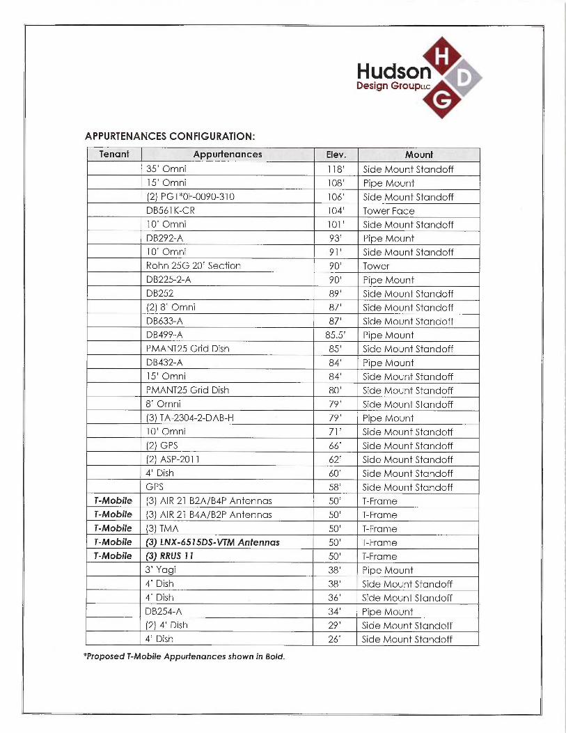
APPURTENANCES CONFIGURATION:
Tenant Appurtenances Elev. Mount
35' Omni 1 18' Side Mount Standoff
15' Omni 108' Pipe Mount
(2) PG1 *OF-0090-310 106' Side Mount Standoff
DB561 K-CR 104' Tower Face
10' Omni 101' Side Mount Standoff
DB292-A 93' Pipe Mount
10' Omni 91' Side Mount Standoff
Rohn 25G 20' Section 90' Tower
DB225-2-A 90' Pipe Mount
DB252 89' Side Mount Standoff
(2) 8' Omni 87' Side Mount Standoff
DB633-A 87' Side Mount Standoff
DB499-A 85.5' Pipe Mount
PMANT25 Grid Dish 85' Side Mount Standoff
DB432-A 84' Pipe Mount
15' Omni 84' Side Mount Standoff
PMANT25 Grid Dish 80' Side Mount Standoff
8' Omni 79' Side Mount Standoff
(3) TA-2304-2-DAB-H 79' Pipe Mount
10' Omni 71' Side Mount Standoff
(2) GPS 66' Side Mount Standoff
(2) ASP-201 1 62' Side Mount Standoff
4' Dish 60' Side Mount Standoff
GPS 58' Side Mount Standoff
T-Mobile (3) AIR 21 B2A/B4P Antennas 50' T-Frame
T-Mobile (3) AIR 21 B4A/B2P Antennas 50' T-Frame
T-Mobile (3) TMA 50' T-Frame
T-Mobile (3) LNX-6515DS-VTM Antennas 50' T-Frame
T-Mobile (3) RRUS 11 50' T-Frame
3' Yagi 38' Pipe Mount
4' Dish 38' Side Mount Standoff
4' Dish 36' Side Mount Standoff
DB254-A 34' Pipe Mount
(2) 4' Dish 29' Side Mount Standoff
4' Dish 26' Side Mount Standoff
*Proposed T-Mobile Appurtenances shown in Bold.

Hudson ~ ,Design Group~~c
T-MOBILE EXISTING/PROPOSED COAX CABLES:
Tenant Coax Cables Elev. Mount
T-Mobile (24) 7/8" Cables 50' Tower FaceT-Mobile (1) Fiber Cable 50' Tower Face
*Proposed T-Mobile Coax Cables shown in Bold.
ANALYSIS RESULTS SUMMARY:
Component Max. Stress Ratio Elev. of Pass/Fail CommentsCom onent ff
Leg 64.4 % 0 - 15 PASSDiagonal 82.7 ~ 50 - 80 PASS ControllingHorizontal 58.6 15 - 20 PASSSecondary
6.3 % 0 - 15 PASSHorizontalTop Girt 16.0 ~ 20 - 50 PASS
Redundant 0.5 ~ 15 - 20 PASSDia onal
Inner Bracing 2.1 ~ 15 - 20 PASS

H udsanDesign Group~~c
DESIGN CRITERIA:
1. EIA/TIA-222-F Structural Standards for Steel Antenna Towers and AntennaSupporting Structures
County: FairfieldWind Load: 85 mph (fastest mile)
105 mph (3 second gust)Ice Thickness: 0.5 inch
2. Approximate height above grade to proposed antennas: 50'
*Calculations and referenced documents are attached*
ASSUMPTIONS:
1. The tower dimensions, member sizes and material strength are as indicated in theprevious structural analysis report prepared by TECTONIC Consultants, dated July12, 2013.
2. The appurtenances configuration is as stated in the previous structural analysisreport prepared by TECTONIC Consultants, dated July 12, 2013. All antennas,coax cables and waveguide cables are assumed to be properly installed andsupported as per the manufacturer's requirements.
3. The tower and foundation are properly constructed and maintained. All structuralmembers and their connections are assumed to be in good condition and arefree from defects with no deterioration to its member capacities at this time.
4. The support mounts and platforms are not analyzed and are consideredadequate to support the loading. The analysis is limited to the primary supportstructure itself.
5. All prior structural modification, if any, are assumed to be as per the datasupplied (if available), and installed properly.
6. The foundation of the tower was not checked due to lack of information. As-builtfoundation drawings and geotechnical report would be required to determinewhether the foundation is capable of supporting the proposed loadings.
HudsonDesign Group~~c
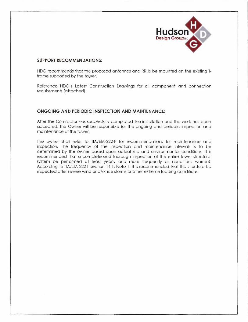
SUPPORT RECOMMENDATIONS:
HDG recommends that the proposed antennas and RRHs be mounted on the existing T-frame supported by the tower.
Reference HDG's Latest Construction Drawings for all component and connectionrequirements (attached).
ONGOING AND PERIODIC INSPTECTION AND MAINTENANCE:
After the Contractor has successfully completed the installation and the work has beenaccepted, the Owner will be responsible for the ongoing and periodic inspection andmaintenance of the tower.
The owner shall refer to TIA/EIA-222-F for recommendations for maintenance andinspection. The frequency of the inspection and maintenance intervals is to bedetermined by the owner based upon actual site and environmental conditions. It isrecommended that a complete and thorough inspection of the entire tower structuralsystem be performed at least yearly and more frequently as conditions warrant.According to TIA/EIA-222-F section 14.1, Note 1: It is recommended that the structure beinspected after severe wind and/or ice storms or other extreme loading conditions.

1~ ~ ~'
1
~~1
•►~ 1\
.~~
-~. '~
'\•~
-
i• . ° -
•
--
- _ - ,
•_i
_- ----
- •
_ •
'
~
~
Hudson ~Design GroupLLc
CALCULATIONS

DESIGNED APPURTENANCE LOADING
ai
m'O nm
N (p
N
N MJ
v
~' ~
N M ~ m
a r ~
~ ~
~ ~z z z
z
m ~Q Q
v ~~ ~ o
th NX v
M J ~J
v ~
Q ~n m U °J dUm
gcoo
X z ~~Scxv ¢ ~ ¢ ¢ mZ X Z Z~ N ~\
VJ ~
J
N ~
N ~
A ~ N p~ ~ ~ ~C C ~\
U N ~ N N m 1p ~ v ~R N (0 r `p ~
U~ O ~ C7 N ~ ~ ~ ~ rnp~ R ~ d ~ U
J D D F- S (q K ~ ti~ ~ ~j
Y
S
s
sS
~L
k:~
TYPE ELEVATION TYPE ELEVATION16' W6X25 100 Omni 2"x15" (GPS) 58
Rahn 25G 20' section 100 - 8D 6' Standoff Arm W10X30 58
D6561 K-CR 100 Omni 2"x15"(GPS) 58
(2) PG1"OF0090.310 100 Omni 2"x15" (GPS) 58
50 602-1 100 6' Standoff Arm W10X30 58
Omni 2"x35' 100 6' Standoff Arm W10X30 58
6' Standoff Arzn W10X30 100 ERICSSON AIR 21 B4A B2P w/Mount 50
Omni 2"x15' 1D0 P~Pe
PM 602-1 100 ERICSSON AIR 21 B4A B2P w/ Mount 50
100'Ma~cShear 700 P~Pe
Omni 2"x1D' gg Style 3 TMA 50
6' SYandoR Artn W10X30 gg Style 3 TMA 50
Rrod 10' BozArm gF Style 3 TMA 50
6' StandoffArm W10X30 gg z 1/2"xT pipe 50
Omni T'x10' gg 2 1/2"x7' pipe 50
DB292-A gg 2 1!2"x7' pipe 50
PM 602-1 g3 Andrew LNX-6515DSVTM w/mount 50
PM 602-1 90 P~Pe (T-Mobile -proposed)
DB225-2-A 90 Andrew LNX-6515DS~VTM w/mount 50pipe
S07D1-1 89 Andrew LNX-6515DSVTM w/mount 50DB252 89 pipe
PM 60&1 85.5 RRUS 11 50
DB499-A 95.5 RRUS 11 50
S0602-1 85 RRU511 b0
DB633A 85 SM 301-1 (T-Mobile-existing) 50
PMANT25 85 SM 301-1 50
2"x12' pipe 84 SM 301-1 50
DB432-A 84 ERICSSON AIR 21 B2AB4P w/Mount 50
6'StandoffArm W1~X30 83 P~Pe
6' Standoff Arm W10X30 63 ERICSSON AIR 21 B2A B4P w/ Mount 50
6' Standoff Arm W10X30 83 P~Pe
6' Standoff Arm W10X30 g3 ERICSSON AIR 21 B2A B4P w/Mount 50Pipe
Omni 2"x15' 83ERICSSON AIR 21 B4A B2P w/Mount 50
S0602-1 83 PipeOmni 2"x8' 83 3' Yagi arrtenna 382"x12' pipe 83 2"x5' pipe 38Omni 2"x8' 83 S0201-1 38Omni 2"x8' 83 Andrew PL4105 38PMANT25 80 Andrew PL4105 3680' Max Shear 8~ 50 201-1 36TA-2304-2-DA&H 79 DB254-A 34TA-23042-DA&H 79 2"x5' pipe 34TA-23042-DA&H 79 SO 201-1 29SO 201-1 ~ Andrew PL4105 29Omni 2"x10' ~ Andrew PL4105 29Andrew PL4105 fi0 S0201-1 2950301-1 60 S0201-1 26°'SP-2a~~ 58 Andrew PL4105 262"x4' pipe 58
ASP-2011 58
100.0 ft
80.0 ft
50.0 $
SYMBOL LISTMARK SIZE MARK SIZE
A L2 1/2XL 1/2x1/4 C L2~ 1/2c1/4
B L2 1/22 1/2x1/8
MATERIAL STRENGTHGRADE Fy Fu GRADE Fy Fu
A36 36 ksi 58 ksi
TOWER DESIGN NOTES1. Tower is located in Fai~eld County, Connecticut.2. Tower designed fora 85 mph basic wind in accordance with the TIA/EIA-222-F Standard.3. Tower is also designed fora 74 mph basic wind with 0.50 in ice.4. Deflections are based upon a 50 mph wind.
20.0 ft
15.0 ft
a.o n
Hudson Design Group, LLC ob` CT11923Cuason~- 1600 Osgood Street, Building 20 North, Suite 3090 Project: 100 ff Se/fSuppo~fin rower
NOfth AlldOvel', MA 01845 client: T-MOBILE Drawn by kW App~d:
Phone: (978) 557-5553 Code: TIA/EIA 222-F Date: 03/05/15 Scale:
FAX: 978 226-5586 Path: Dwg N

Job Page
Hudson~~ CT11923C 1 of 13Design Groupuc~
Hudson Design Group, LLC Project Date
16000sgooasr~eet, Butadzng2oNoYrh, 100 ft Seif Supporting Tower 11:02:03 03/05/15Suite 3090
North Andover, MA 01845 Client Designed byPhone: (978) 557-5553 T-MOBILE kWFAX. (978) 226-5586
Tower In ut Data
The. main tower is a 4x free standing tower with an overall height of 100.00 ft above the ground line.The base of the tower is set at an elevation of 0.00 ft above the ground line.The face width of the tower is 8.50 ft at the top and 21.00 ft at the base.This tower is designed using the TIA/EIA-222-F standard.The following design criteria apply:
Tower is located in Fairfield County, Connecticut.Basic wind speed of 85 mph.Nominal ice thickness of 0.5000 in.Ice density of 56 pcf.A wind speed of 74 mph is used in combination with ice.Temperature drop of 50 °F.Deflections calculated using a wind speed of 50 mph.A non-linear (P-delta) analysis was used.Pressures are calculated at each section.Stress ratio used in tower member design is 1.333.Local bending stresses due to climbing loads, feed line supports, and appurtenance mounts are not considered.
Tavver section Geornet
Tower Tower Assembly Description Section Number SectionSection Elevation Database Width of Length
Sections
Tl 100.00-80.00 8.50 1 20.00T2 80.00-50.00 11.42 1 30.00T3 50.00-20.00 15.00 1 30.00T4 20.00-15.00 18.58 1 5.00TS 15.00-0.00 19.19 1 15.00
Tower Section Geomet cont'd_ ~ _ ~. - - -- - -~- =~~~ ~_~..~_ ,.~a ~,~-m,Tower Tower Diagonal Bracing Has Has Top Girt Bottom GirtSection Elevation Spacing Type KBrace Horizontals Offset Offset
Endft ft Panels in in
T1 100.00-80.00 6.67 XBrace No No 0.0000 0.0000T2 80.00-50.00 7.50 X Brace No No 0.0000 0.0000T3 50.00-20.00 10.00 X Brace No No 0.0000 0.0000T4 20.00-15.00 5.00 Kl Down No Yes 0.0000 0.0000TS 15.00-0.00 14.92 X Brace No Yes 0.0000 1.0000
Tower Section Geomet cont'd

Job Page
H~adsan~Q, CT11923C 2 of 13Cosign GwuplP.C~
Hudson Design Group, LLC Project Date
1600 osgoodstreet, Building 20 North, 100 ft Self Supporting Tower 11:02:03 03/05/15Suite 3090
North Andover, MA 01845 Client Designed byPhone: (978) 557-5553 T-MOBILE kWFAX.• (978) 226-5586
Tower Leg Leg Leg Diagonal Diagonal DiagonalElevation Type Si:e Grade Type Sipe Grade
Tl 1Q0.00-80.00 Equal Angle LSx5x3/8 A36 Single Angle L21c2 1/2/16 A36(36 ksi) (36 ksi}
T2 80.00-50.00 Equal Angle L6x6x3/8 A36 Equal Angle L2 1/2~, 1/2x3/16 A36(36 ksi) (36 ksi)
T3 50.00-20.00 Equal Angle L6x6x9/16 A36 Single Angle L3~ 1/2x1/4 A36(36 ksi) (36 ksi)
T4 20.00-15.00 Equal Angle L6x6x1/2 A36 Equal Angle L2 1/2~; 112x1/4 A36(36 ksi) (36 ksi)
TS 15.00-0.00 Equal Angle L6x6x1/2 A36 Single Angle L3 1/2x4x1/4 A36_ (36 ksi) (36 ksi)
Tower Section Geomet cont'd
Tower Top Girt Top Girt Top Girt Bottom Girt Bottom Girt Bottom GirtElevation Type Sipe Grade Type Sipe Grade
T1 100.00-80.00 Single Angle L2 1/2}c2 1/2x3/16 A36 Equal Angle A36(36 ksi) (36 ksi)
TZ 80.00-50.00 Single Angle L2x2 1/2/16 A36 Equal Angle A36(36 ksi) (36 ksi~
T3 50.00-20.00 Single Angle L2x3x3/16 A36 Equal Angle A36_T~~~ (36 ksi) X36 ksi
Tower Section Geomet cont'd__ ____ __ __
Tower No Mid Girt Mid Girt Mid Girt Hon~ontal Horizontal Ho7 i~ontalElevation. of Type Sipe Grade Type Size Grade
Midft Girts
T4 20.00-15.00 None Equal Angle A36 Equal Angle L3x3x1/4 A36~~ ~,,-_~ - — (36 ksi) _ ~ (36 ksi)
Tower Section Geomet (cont'd
Tower ~ ~ Secondary Secondary Horizontal Secondary Inner Bracing Inner Bracing Sipe Inner BracingElevation Horizontal Type Size Horizontal Type Grade
Grade
T4 20.00-15.00 Equal Angle A36 Single Angle L2~ 1/2x1/4 A36(36 ksi) (36 ksi)
TS 15.00-0.00 Equal Angle L3 1/2ac3 1/2x1/4 A36 Single Angle A36__—_—_- _ (36 ksi)
Tower Section Geomet (cont'd

Job Page
Hwdson~- CT11923C 3 of 13Design Group LLC~,.
Hudso~Z Design Group, LLC Project Date
1600 osgoodsr~eet, Buttd~~gzoNoYrh, 100 ft Self Supporting Tower 11:02:03 03/05/15Suite 3090
North Andover, MA 01845 Client Designed byPhone: (978)557-5553 T-MOBILE kWFAX.' (978) 226-5586
Taiver Redundant Redundant Redundant K FactorElevation Bracing Type Size
GradeftT4 A36 Diagonal (1) Equal Angle L2 1/2~ 1/2x1/8 1 ~~
20.00-15.00_ (36 ksi ~~~
Feed Line/Linear A urtenances -Entered As Round Or FlatW~ $m._ v~~t= _ __ . ~_ ~~~=
Description. Face Allow Component Placeme~at Face Lateral # # Clear Width or Perimeter Weightor Shield Type Offset Offset PeY Spacing DiameterLeg ft in (Frac FW) Row in in in ~~
LDF4-SOA B No Ar (CfAe) 85.50 - 15.00 0.0000 -0.5 1 1 0.6300 0.6300 0.15(1/2 FOAM)LDF4-SOA B No Ar (CfAe) 100.00 - 15.00 0.0000 -0.5 1 1 0.6300 0.6300 0.15(1/2 FOANnLDFS-SOA B No Ar (CfAe) 90.00 - 15.00 0.0000 -0.5 1 1 1.0900 1.0900 033(7/8 FOAN~LDFS-SOA B Yes Ar (CfAe) 50.00 - 15.00 -2.5000 0.35 16 8 1.0900 1.0900 0.33(7/8 FOANnCATSe(1/4") B No Ar (CfAe) 100.00 - 15.00 -2.5000 0.4 2 1 0.2638 0.2638 0.15Feedline B No Af (CfAe) 60.00 - 15.00 -2.5000 0.35 1 1 3.0000 3.0000 12.0000 8.40
Ladder (.SflLDFS-SOA B No Ar (CfAe) 100.00 - 15.00 -2.0000 0.49 4 2 1.0900 1.0900 033(7/8 FOAM)
LDFS-SOA C No Ar (CfAe) 83.00 - 15.00 0.0000 -0.47 3 3 1.0900 1.0900 0.33(7/8 ROANLDFS-SOA C No Ar (CfAe) 100.00 - 15.00 0.0000 -0.46 3 3 1.0900 1.0900 033(7/8 FOAIv~LDF7-SOA C No Ar (CfAe) 100.00 - 15.00 0.0000 -0.48 1 1 1.9800 1.9800 0.82
(1-5/8 FOAM)LDF4-SOA C No Ar (CfAe) 79.00 - 15.00 0.0000 -0.48 2 2 0.6300 0.6300 0.15(1/2 FOAN~LDF1-SOA C No Ar (CfAe) 38.00 - 15.00 0.0000 -0.25 2 2 03500 03500 0.06(1/4 FOAN~CATSe(1/4") C No Ar (CfAe) 100.00 - 15.00 0.0000 -01 1 1 0.2638 0.2638 0.15LDF1-SOA C No Ar (CfAe) 29.00 - 15.00 0.0000 -0.1 1 1 03500 03500 0.06
(1/4 FOAM)LDF4-SOA C No Ar (CfAe) 29.00 - 15.00 0.0000 -0.1 1 1 0.6300 0.6300 0.15
(1/2 FOAM)LDF1-SOA C No Ar (CfAe) 26.00 - 15.00 0.0000 03 2 2 03500 0.3500 0.06(1/4 FOAM)
LDF4-SOA D No Ar (CfAe) 28.00 - 15.00 -2.0000 -0.49 8 3 0.6300 0.6300 0.15(1/2 FOAM)LDF4-SOA D No Ar (CfAe) 34.00 - 15.00 -2.0000 -0.49 7 3 0.6300 0.6300 0.15
(1/2 FOAN~LDF4-SOA D No Ar (CfAe) 58.00 - 15.00 -2.0000 -0.49 6 2 0.6300 0.6300 0.15
(1/2 FOAIv~LDF4-SOA D No Ar (CfAe) 80.00 - 15.00 -2.0000 -0.49 4 2 0.6300 0.6300 0.15(1/2 FOANnLDF4-SOA D No Ar (CfAe) 85.00 - 15.00 -2.0000 -0.49 2 1 0.6300 0.6300 0.15(1/2 FOAM)LDF4-SOA D No Ar (CfAe) 100.00 - 15.00 -2.0000 -0.49 1 1 0.6300 0.6300 0.15(1/2 FOAM)LDF4.5-50 D No Ar (CfAe) 89.00 - 15.00 -2.0000 -0.49 1 1 0.8700 0.8700 0.15(5/8 FOAM)LDFS-SOA D No Ar (CfAe) 100.00 - 15.00 -2.0000 -0.49 1 1 1.0900 1.0900 0.33
(7/8 FOAIvn

PaJob 9eHIJdSt)ri CT11923C 4 of 13Design Graup uc~_
Hudson Design Group, LLC Project Date
1600 osgooasr~eea, B~rZdt~g2oNorrh, 100 ft Self Supporting Tower 11:02:03 03/05/15Suite 3090
North Andover, MA 01845 Client Designed byPhone: (978) 557-5553 T-MOBILE kWFAX (978) 226-5586
Description Face Allow Component Placemetat FaceLateral # # Clear Width or Perimeter Weightor Shield Type Offset Offset Per Spacing DiameterLeg ft in. (Fr^ac FYT~J Ro~v in in in.
LDF4-SOA D No Ar (CfAe) 79.00 -15.00 0.0000 -0.45 1 1 0.6300 0.6300 0.15(1/2 FOAM)CATSe(1/4") D No Ar (CfAe) 100.00 - 15.00 0.0000 -0.45 1 1 02638 0.2638 0.15CATSe(1/4") D No Ar (CfAe) 100.00 - 15.00 0.0000 -0.45 1 1 0.2638 0.2638 0.15LDF7-SOA D No Ar (CfAe) 100.00 - 15.00 0.0000 -0.45 1 1 1.9800 1.9800 0.82
(1-5/8 FOAM)LDF4-SOA D No Ar (CfAe) 60.00 - 15.00 0.0000 -0.45 1 1 0.6300 0.6300 0.15
(1/2 FOAM)LDFS-SOA D No Ar (CfAe) 58.00 - 15.00 0.0000 0.5 1 1 1.0900 1.0900 033(7/8 FOAN~
LDFS-SOA A No Ar (CfAe) 50.00 - 15.00 -2.0000 -0.4 8 8 1.0900 1.0900 0.33(7/8 FOANnLDFS-SOA A No Ar (CfAe) 100.00 - 15.00 0.0000 -0.4 1 1 1.0900 1.0900 033(7/8 FOAlV~
Feedline A No Af (CfAe) 50.00 - 15.00 -2.0000 -0.4 1 1 3.0000 3.0000 12.0000 8.40Ladder (AflLDFS-SOA A No Ar (CfAe) 96.00 - 15.00 -12.0000 0 2 2 1.0900 1.0900 0.33(7/8 FOAN~LDF4-SOA A No Ar (CfAe) 100.00 - 15.00 0.0000 0 1 1 0.6300 0.6300 0.15
(1/2 FOAM)2" Rigid A No Ar (CfAe) 50.00 - 15.00 0.0000 0 1 1 2.0000 2.0000 2.80Conduit2" Rigid B No Ar (CfAe) 50.00 - 15.00 0.0000 0 1 1 2.0000 2.0000 2.80Conduit
User Defined Loads
Description Elevation Offset Azimuth Weight ~~F F WindForce ~ CqA~~From Angle
Centroid__ ft ft Zb lb Ib Ib ft~
100' Marc Shear 100.00 0.00 0.0000 No Ice 0.00 0.00 0.00 1783.00 60.43Ice 0.00 0.00 0.00 2715.00 122.69
Service 0.00 0.00 0.00 618.00 60.5380' Max Shear 80.00 0.00 0.0000 No Ice 0.00 0.00 0.00 -722.00 26.08
Ice 0.00 0.00 0.00 -1100.00 52.98Service 0.00 0.00 0.00 -251.00 26.20
Discrete Tower Loads
Description Face Offset Offsets: Azimuth Placement C,~Aa CQA.9 Weightor Type Horn Adjustment Front SideLeg Later^al
Vertft ft ft~ ~ lb
16' W6X25
Rohn 25G 20' section
C None 0.0000 100.00 No Ice 0.09 11.91 400.001/2" Ice 0.15 1320 455.85No Ice 20.00 20.00 400.001/2" Ice 2228 2228 502.70No Ice 5.32 532 43.001/2" Ice 6.83 6.83 7339
None 0.0000 100.00 - 80.00
DB561K-CR D From Face 0.00 0.0000 100.000.00

Job Page
HudsQn~ CT11923C 5 of 13Design GraupuC~.
Hudson Design Group, LLC Project Date
1600 osgooas~eer, ButtatngzoNoYrh, 100 ft Self Supporting Tower 11:02:03 03/05/15Suite 3090
North Andover, MA 01845 Client Designed byPhone: (978) 557-5553 T-MOBILE ~FAX. (978) 226-5586
Description Face Offset Offsets: A<-imuth Placement CaAA CgAA Weightor Type Ho~z Adjustment Front SideLeg Lateral
Vertft ft f[~ fly lbftft4.00
(2) PGl *OF-0090-310 C From Leg 0.00 0.0000 100.00 No Ice 3.00 3.00 30.000.00 1/2" Ice 4.03 4.03 51.796.00
SO 602-1 C From Leg 0.00 0.0000 100.00 No Ice 2.72 12.93 146.000.00 1/2" Ice 4.11 17.82 223.000.00
Omni 2"x35' A From Leg 6.00 0.0000 100.00 No Ice 7.00 7.00 60.000.00 1/2" Ice 10.53 10.53 113.6818.00
6' Standoff Arm W 10X30 A From Leg 3.00 0.0000 100.00 No Ice 0.59 7.33 180.000.00 1/2" Ice 0.70 7.87 222.850.00
Omni 2"x15' B From Face 0.00 0.0000 100.00 No Ice 3.00 3.00 30.000.00 1/2" Ice 4.53 4.53 53.148.00
PM 602-1 B From Leg 0.00 0.0000 100.00 No Ice 525 1.58 93.000.00 1/2" Ice 6.50 1.95 118.000.00
Omni 2"x10' D From Face 6.00 0.0000 96.00 No Ice 2.00 2.00 20.000.00 1/2" Ice 3.02 3.02 35.505.00
Omni 2"x10' D From Face 6.00 0.0000 96.00 No Ice 2.00 2.00 20.000.00 1/2"Ice 3.02 3.02 35.50-5.00
6'StandoffArmW10X30 D From Face 3.00 0.0000 96.00 No Ice 0.59 7.33 180.000.00 1/2" Ice 0.70 7.87 222.850.00
DB292-A B None 0.0000 93.00 No Ice 1.80 1.80 15.001/2" Ice 3.24 324 19.50
PM 602-1 B None 0.0000 93.00 No Ice 5.25 1.58 93.001/2" Ice 6.50 1.95 118.00
DB225-2-A B None 0.0000 90.00 No Ice 3.21 3.21 74.001/2" Ice 5.78 5.78 96.20
PM 602-1 B None 0.0000 90.00 No Ice 5.25 1.58 93.001/2" Ice 6.50 1.95 118.00
DB252 C From Leg 3.00 0.0000 89.00 No Ice 3.20 3.20 26.000.00 1/2" Ice 5.76 5.76 33.800.00
SO 701-1 C From Leg 1.50 0.0000 89.00 No Ice 0.85 1.67 65.000.00 1/2" Ice 1.14 2.34 79.000.00
DB499-A B None 0.0000 85.50 No Ice 0.25 0.25 5.001/2" Ice 0.45 0.45 6.50
PM 602-1 B None 0.0000 85.50 No Ice 5.25 1.58 93.001/2" Ice 6.50 1.95 118.00
DB633-A D From Face 4.00 0.0000 85.00 No Ice 0.65 0.65 8.000.00 1/2" Ice 0.86 0.86 13.572.00
SO 602-1 D From Face 2.00 0.0000 85.00 No Ice 2.72 12.93 146.000.00 1/2" Ice 4.11 17.82 223.000.00
DB432-A C None 0.0000 84.00 No Ice 0.30 0.30 5.001/2" Ice 0.54 0.54 6.50
2"x12' pipe C None 0.0000 84.00 No Ice 2.85 2.85 45.001/2" Ice 4.08 4.08 66.36
2"x12' pipe D None 0.0000 83.00 No Ice 2.85 2.85 45.00

Job Page
Hudson~~i CT11923C 6 of 13DasiBn Graupuc~
Hudson Design Group, LLC Project Date
16000sgoodStreet, Buttdtng2oNorrh, 100 ft Self Supporting Tower 11:02:03 03/05/15Suite 3090
North Andover, MA 01845 Client Designed byPhone: (978) 557-5553 T-MOBILE kWF.9X.• (978) 226-5586
Description Face Offset Offsets: Azimuth Placement 4 ~ CaAA C,~AA T Weightor Type Hors Adjustment Front SideLeg Lateral
Yertft ft fig fry Ib
t1/2" Ice 4.08 4.08 6636
Omni 2"x8' B From Leg 6.00 0.0000 83.00 No Ice 1.60 1.60 35.000.00 1/2" Ice 2.42 2.42 47.454.00
Omni 2"x8' C From Leg 6.00 0.0000 83.00 No Ice 1.60 1.60 35.000.00 l/2" Ice 2.42 2.42 47.454.00
Omni 2"x8' C From Leg 6.00 0.0000 83.00 No Ice 1.60 1.60 35.000.00 1/2" Ice 2.42 2.42 47.45-4.00
6' Standoff Arm W 10X30 A From Leg 3.00 0.0000 83.00 No Ice 0.59 7.33 180.000.00 1/2" Ice 0.70 7.87 222.850.00
6' Standoff Arm W 10X30 B From Leg 3.00 0.0000 83.00 No Ice 0.59 733 180.000.00 1/2" Ice 0.70 7.87 222.850.00
6' StandoffArm W10X30 C From Leg 3.00 0.0000 83.00 No Ice 0.59 7.33 180.000.00 1/2" Ice 0.70 7.87 222.850.00
6' StandoffArm W10X30 D From Leg 3.00 0.0000 83.00 No Ice 0.59 733 180.000.00 1/2" Ice 0.70 7.87 222.850.00
Omni 2"x15' B From Face 4.00 0.0000 83.00 No Ice 3.00 3.00 30.000.00 1/2" Ice 4.53 4.53 53.141.00
SO 602-1 C None 0.0000 83.00 No Ice 2.72 12.93 146.001/2" Ice 4.11 17.82 223.00
TA-2304-2-DAB-H B None 0.0000 79.00 No Ice 3.15 3.15 15.001/2" Ice 3.63 3.63 35.00
TA-2304-2-DAB-H C None 0.0000 79.00 No Ice 3.15 3.15 15.001/2" Ice 3.63 3.63 35.00
TA-2304-2-DAB-H D None 0.0000 79.00 No Ice 3.15 3.15 15.001/2"Ice 3.63 3.63 35.00
Omni 2"x10' B From Leg 1.00 0.0000 66.00 No Ice 2.00 2.00 20.000.00 1/2" Ice 3.02 3.02 35.505.00
SO 201-1 B None 0.0000 66.00 No Ice 2.96 2.11 96.001/2" Ice 4.10 2.93 117.00
SO 301-1 D None 0.0000 60.00 No Ice 1.00 0.90 23.001/2" Ice 139 1.42 33.00
ASP-2011 A From Leg 6.00 0.0000 58.00 No Ice 1.06 1.06 4.000.00 1/2" Ice 1.93 1.93 13.224.00
Omni 2"x15" (GPS) A From Leg 3.00 0.0000 58.00 No Ice 0.17 0.17 10.000.00 1/2" Ice 0.27 0.27 12.140.00
6' Standoff Arm W10X30 A From Leg 3.00 0.0000 58.00 No Ice 0.59 733 180.000.00 1/2" Ice 0.70 7.87 222.850.00
Omni 2"x15" (GPS) B From Leg 6.00 0.0000 58.00 No Ice 0.17 0.17 10.000.00 1/2" Ice 0.27 0.27 12.148.00
6' StandoffArm W10X30 B From Leg 3.00 0.0000 58.00 No Ice 0.59 733 180.000.00 1/2" Ice 0.70 7.87 222.850.00
Omni 2"x15" (GPS) C From Leg 6.00 0.0000 58.00 No Ice 0.17 0.17 10.000.00 1/2" Ice 0.27 0.27 12.14

Job Page
Hudson CT11923C 7 of 13Design Groupuc
Hudson Design Group, LLC Project Date
16000sgoodStreet, Building 20 North, 100 ft Self Supporting Tower 11:02:03 03/05/15Suite 3090
Norrh Andover, MA 01845 Client Designed byPhone: (978) 557-5553 T-MOBIL EFAX.• (978J 226-5586 kW
Description Face Offset Offsets.• Azimuth Placement C,~A,4 CfiA.9 Weightor Type Horz Adjustmevrt Front SideLeg Lateral
Vert
.f~ ft .f~ .f~ Ibf~fr
8.006' Standoff Arm W 10X30 C From Leg 3.00 0.0000 58.00 No Ice 0.59 7.33 180.00
0.00 1/2" Ice 0.70 7.87 222.850.00
ASP-2011 D From Leg 0.00 0.0000 58.00 No Ice 1.06 1.06 4.000.00 1/2" Ice 1.93 1.93 13.224.00
2"x4' pipe D From Leg 0.00 0.0000 58.00 No Ice 0.87 0.87 14.000.00 1/2" Ice 1.11 1.11 21330.00
~*******
SM 301-1 A From Leg 2.00 0.0000 50.00 No Ice 15.43 10.89 434.00(T-Mobile -existing) 0.00 1/2" Ice 20.15 15.23 614.00
0.00SM 301-1 B From Leg 2.00 0.0000 50.00 No Ice 15.43 10.89 434.00
0.00 1/2" Ice 20.15 15.23 614.000.00
SM 301-1 D From Leg 2.00 0.0000 50.00 No Ice 15.43 10.89 434.000.00 1/2" Ice 20.15 1523 614.000.00
ERICSSON AIR 21 B2A A From Leg 3.00 0.0000 50.00 No Ice 6.83 5.64 112.18B4P w/ Mount Pipe 0.00 1/2" Ice 735 6.48 169.02
0.00ERICSSON AIR 21 B2A B From Leg 3.00 0.0000 50.00 No Ice 6.83 5.64 112.18B4P w/ Mount Pipe 0.00 1/2" Ice 7.35 6.48 169.02
0.00ERICSSON AIR 21 B2A D From Leg 3.00 0.0000 50.00 No Ice 6.83 5.64 112.18B4P w/Mount Pipe 0.00 I/2" Ice 7.35 6.48 169.02
0.00ERICSSON AIR 21 B4A A From Leg 3.00 0.0000 50.00 No Ice 6.81 5.63 112.15
B2P w/ Mount Pipe 0.00 1/2" Ice 7.33 6.47 168.900.00
ERICSSON AIR 21 B4A B From Leg 3.00 0.0000 50.00 No Ice 6.81 5.63 112.15B2P w/ Mount Pipe 0.00 1/2" Ice 733 6.47 168.90
0.00ERICSSON AIR 21 B4A D From Leg 3.00 0.0000 50.00 No Ice 6.81 5.63 112.15B2P w/ Mount Pipe 0.00 1/2" Ice 7.33 6.47 168.90
0.00Style 3 TMA A From Leg 2.00 0.0000 50.00 No Ice 0.78 021 11.30
0.00 1/2" Ice 0.90 0.30 15.860.00
Style 3 TMA B From Leg 2.00 0.0000 50.00 No Ice 0.78 021 11.300.00 1/2" Ice 0.90 0.30 15.860.00
Style 3 TMA D From Leg 2.00 0.0000 50.00 No Ice 0.78 0.21 11300.00 1/2" Ice 0.90 0.30 15.860.00
2 1/2"x7' pipe A From Leg 3.00 0.0000 50.00 No Ice 1.73 1.73 41.000.00 1/2" Ice 2.09 2.09 53.770.00
2 1/2"x7' pipe B From Leg 3.00 0.0000 50.00 No Ice 1.73 1.73 41.000.00 1/2" Ice 2.09 2.09 53.770.00
2 1/2"x7' pipe D From Leg 3.00 0.0000 50.00 No Ice 1.73 1.73 41.000.00 1/2" Ice 2.09 2.09 53.770.00
+*****+*

Job Page
Hudson4~ CT11923C 8 of 13Deaien GroupucO
Hudson Design Group, LLC Project Date
16000sgoodStreet, Building 20 North, 100 ft Self Supporting Tower 11:02:03 03/05/15Suite 3090
North Andover, MA 01845 Client Designed byPhone: (978) 557-5553 T-MOBILE kWFAX.• (978J 226-5586
Description Face Offset Offsets: Airreuth Placement C~A,~ C,~AA Werghror Type Hora Adjustment Front SideLeg Lateral
Vertft ft fr' fiz IbJ`tft
Andrew LNX-6515DS-VTM A From Leg 3.00 0.0000 50.00 No Ice 11.72 1028 102.41w/mount pipe 0.00 1/2" Ice 12.44 11.81 19622
(T-Mobile -proposed) 0.00Andrew LNX-6515DS-VTM B From Leg 3.00 0.0000 50.00 No Ice 11.72 10.28 102.41
w/mount pipe 0.00 1/2" Ice 12.44 11.81 196.220.00
Andrew LNX-6515DS-VTM D From Leg 3.00 0.0000 50.00 No Ice 11.72 10.28 102.41w/mount pipe 0.00 1/2" Ice 12.44 11.81 196.22
0.00RRUS 11 A From Leg 2.00 0.0000 50.00 No Ice 3.25 1.37 50.70
0.00 1/2" Ice 3.49 1.55 71.500.00
RRUS 11 B From Leg 2.00 0.0000 50.00 No Ice 3.25 137 50.700.00 1/2" Ice 3.49 1.55 71.500.00
RRUS 11 D From Leg 2.00 0.0000 50.00 No Ice 3.25 1.37 50.700.00 1/2" Ice 3.49 1.55 71.500.00
**********
3' Yagi antenna D From Leg 1.00 0.0000 38.00 No Ice 0.70 0.35 10.000.00 1/2" Ice 0.95 0.48 36350.00
2"x5' pipe D From Leg 0.00 0.0000 38.00 No Ice 1.19 1.19 19.000.00 1/2" Ice 1.50 1.50 28.090.00
DB254-A D From Leg 0.00 0.0000 34.00 No Ice 1.10 1.10 10.000.00 1/2" Ice 1.98 1.98 13.000.00
2"x5' pipe D From Leg 0.00 0.0000 34.00 No Ice 1.19 1.19 19.000.00 1/2" Ice 1.50 1.50 28.090.00
SO 201-1 C From Face 0.00 0.0000 38.00 No Ice 2.96 2.11 96.000.00 1/2" Ice 4.10 2.93 117.000.00
SO 201-1 C From Face 0.00 0.0000 36.00 No Ice 2.96 2.11 96.000.00 1/2" Ice 4.10 2.93 117.000.00
SO 201-1 C From Face 0.00 0.0000 29.00 No Ice 2.96 2.11 96.000.00 1/2" Ice 4.10 2.93 117.000.00
SO 201-1 C From Face 0.00 0.0000 29.00 No Ice 2.96 2.11 96.000.00 1/2" Ice 4.10 2.93 117.000.00
SO 201-1 C From Face 0.00 0.0000 26.00 No Ice 2.96 2.11 96.000.00 1/2" Ice 4.10 2.93 117.000.00
Pirod 10' Box Arm C None 0.0000 96.00 No Ice 5.00 5.00 250.001/2" Ice 10.00 10.00 300.00
6' StandoffArm W10X30 C None 0.0000 96.00 No Ice 0.59 733 180.001/2" Ice 0.70 7.87 222.85

Job Page
Hudson4~i CT11923C 9 of 13Deaf9n GroupucO
Hudson Design Group, LLC Project Date
16000sgoodStreet,Bu~tctt~gzoNorth, 100 ft Self Supporting Tower 11:02:03 03/05/15Suite 3090
North Andover, MA 01845 Client Designed byPhone: (978) 557-5553 T-MOBIL EFAX.• (978) 226-5586 kw
Dishes
Description Face Dish Offset Offsets: Azimuth 3 dB Elevafron Outside Aperture Weightor Type Type Hors Adjustment Beam Diameter AreaLeg Lateral Width
Vertft ft ft f[z Ib
PMANT25 D Grid From 1.00 0.0000 85.00 2.83 No Ice 5.19 8.20Face 0.00 1/2" Ice 6.68 42.48
0.00PMANT25 D Grid From 1.00 0.0000 80.00 2.83 No Ice 5.19 820
Face 0.00 1/2" Ice 6.68 42.480.00
Andrew PL4-105 D Paraboloid w/o From 1.00 0.0000 60.00 4.00 No Ice 12.57 110.00Radome Face 0.00 1/2" Ice 13.10 180.00
0.00Andrew PL4-105 C Pazaboloid w/o From 1.00 0.0000 38.00 4.00 No Ice 12.57 110.00
Radome Face 0.00 1/2" Ice 13.10 180.000.00
Andrew PL4-105 C Pazaboloid w/o From 1.00 0.0000 36.00 4.00 No Ice 12.57 110.00Radome Face 0.00 1/2" Ice 13.10 180.00
0.00Andrew PL4-105 C Paraboloid w/o From 1.00 0.0000 29.00 4.00 No Ice 12.57 110.00
Radome Face 0.00 1/2" Ice 13.10 180.000.00
Andrew PL4-105 C Paraboloid w/o From 1.00 0.0000 29.00 4.00 No Ice 12.57 110.00Radome Face 0.00 1/2" Ice 13.10 180.00
0.00Andrew PL4-105 C Pazaboloid w/o From 1.00 0.0000 26.00 4.00 No Ice 12.57 110.00
Radome Face 0.00 1/2" Ice 13.10 180.000.00
Load Combinations
Comb. DescriptionNo.1 Dead Only2 Dead+Wind 0 deg - No Ice3 Dead+Wind 45 deg - No Ice4 Dead+Wind 90 deg - No Ice5 Dead+Wind 135 deg - No Ice6 Dead+Wind 180 deg - No Ice7 Dead+Wind 225 deg - No Ice8 Dead+Wind 270 deg - No Ice9 Dead+Wind 315 deg - No Ice10 Dead+Ice+Temp11 Dead+Wind 0 deg+Ice+Temp12 Dead+Wind 45 deg+Ice+Temp13 Dead+Wind 90 deg+Ice+Temp14 Dead+Wind 135 deg+Ice+Temp15 Dead+Wind 180 deg+Ice+Temp16 Dead+Wind 225 deg+Ice+Temp17 Dead+Wind 270 deg+Ice+Temp18 Dead+Wind 315 deg+Ice+Temp19 Dead+Wind 0 deg -Service20 Dead+Wind 45 deg -Service21 Dead+Wind 90 deg -Service22 Dead+Wind 135 deg -Service


EBI Consulting~,.
environmental ~ engineering ~ due diligence
RADIO FREQUENCY EMISSIONS ANALYSIS REPORT
EVALUATION OF HUMAN EXPOSURE POTENTIAL
TO NON-IONIZING EMISSIONS
T-Mobile Existing Facility
Site ID: CT11923C
W. View Dr G
T7 West View Drive
Danbury, CT 06810
March 18, 2
015
EBI Project N
umber: 6215001629
Site (;omplianc~ ~+,~rmary
Compliance Status: COMPLIANT
Site total MPE4o of
FCC general public
~i~,94
allowable limit:
21 B Street
~ Burlington, MA 01803
Tel: (781) 273.2500
Fax: (781) 273.3311

EBI Consultin:~ environmental ~ engineering I due diligence
March 18, 2015
T-Mobile USAAttn: Jason Overbey, RF Manager35 Griffin Road SouthBloomfield, CT 06002
Emissions Analysis for Site: CTll923C — W. View Dr_GT
EBI Consulting was directed to analyze the proposed T-Mobile facility located at 7 West View Drive,
Danbury, CT, for the purpose of determining whether the emissions from the Proposed T-Mobile
Antenna Installation located on this property are within specified federal limits.
All information used in this report was analyzed as a percentage of current Maximum Permissible
Exposure (% MPE) as listed in the FCC OET Bulletin 65 Edition 97-01 and ANSUIEEE Std C95.1. The
FCC regulates Maximum Permissible Exposure in units of microwatts per square centimeter (µW/cm2).
The number of µW/cmz calculated at each sample point is called the power density. The exposure limit
for power density varies depending upon the frequencies being utilized. Wireless Carriers and Paging
Services use different frequency bands each with different exposure limits, therefore it is necessary to
report results and limits in terms of percent MPE rather than power density.
All results were compared to the FCC (Federal Communications Commission) radio frequency exposure
rules, 47 CFR 1.1307(b)(1) — (b)(3), to determine compliance with the Maa~imum Permissible Exposure
(MPE) limits for General Population/LTncontrolled environments as defined below.
General population uncontrolled exposure limits apply to situations in which the general public may be
exposed or in which persons who are exposed as a consequence of their employment may not be made
fully aware of the potential for exposure or cannot exercise control over their exposure. Therefore,
members of the general public would always be considered under this category when exposure is not
employment related, for example, in the case of a telecommunications tower that exposes persons in a
nearby residential area.
Public exposure to radio frequencies is regulated and enforced in units of microwatts per square
centimeter (µW/cmZ). The general population exposure limit for the 700 MHz Band is 467 µW/cm2, and
the general population exposure limit for the PCS and AWS bands is 1000 µW/cmZ. Because each carrier
will be using different frequency bands, and each frequency band has different exposure limits, it is
necessary to report percent of MPE rather than power density.
21 E Street B~ar[ingto;~, MR 01803 Tel: X781) 27 .2500 Fax: ~78~ 1 ?73.311

EBI Consultinga► environmental I engineering ~ due diligence
Occupational/controlled exposure limits apply to situations in which persons are exposed as a
consequence of their employment and in which those persons who are exposed have been made fully
aware of the potential for exposure and can exercise control over their exposure. Occupational/controlled
exposure limits also apply where exposure is of a transient nature as a result of incidental passage tl~►rougha location where exposure levels may be above general population/uncontrolled limits (see below), as
long as the exposed person has been made fully aware of the potential for exposure and can exercise
control over his or her exposure by leaving the area or by some other appropriate means.
Additional details can be found in FCC OET 65.
CALCULATIONS
Calculations were done for the proposed T-Mobile Wireless antenna facility located at 7 West View
Drive, Danbury, CT, using the equipment information listed below. All calculations were performed per
the specifications under FCC OET 65. Since T-Mobile is proposing highly focused directional panel
antennas, which project most of the emitted energy out toward the horizon, all calculations were
performed assuming a lobe representing the maximum gain of the antenna per the antenna manufactures
supplied specifications, minus 10 dB, was focused at the base of the tower. For this report the sample
point is the top of a 6 foot person standing at the base of the tower.
For all calculations, all equipment was calculated using the following assumptions:
1) 2 GSM channels (PCS Band - 1900 MHz) were considered for each sector of the proposed
installation. These Channels have a transmit power of 30 Watts per Channel
2) 2 UMTS channels (AWS Band — 2100 MHz) were considered for each sector of the proposed
installation. These Channels have a transmit power of 30 Watts per Channel.
3) 2 LTE channels (AW5 Band — 2100 MHz) were considered for each sector of the proposed
installation. These Channels have a transmit power of 60 Watts per Channel.
4) 1 LTE channel (700 MHz Band) was considered for each sector of the proposed installation.
This channel has a transmit power of 30 Watts.
5) All radios at the proposed installation were considered to be ruru~ing at full power and were
uncombined in their RF transmissions paths per carrier prescribed configuration. Per FCC
OET Bulletin No. 65 -Edition 97-01 recommendations to achieve the maximum anticipated
value at each sample point, all power levels emitting from the proposed antenna installation
are increased by a factor of 2.56 to account for possible in-phase reflections from the
surrounding environment. This is rarely the case, and if so, is never continuous.
?1 ~ Stt~eet ~ Burlington, n~~ 038Q: Tel: {731) 2?3.2500 Fax: (781) z73.331~

EBI Consultin,► environmental 0 engineering I due diligence
6) For the following calculations the sample point was the top of a six foot person standing at
the base of the tower. The maximum gain of the antenna per the antenna manufactures
supplied specifications minus 10 dB was used in this direction. This value is a very
conservative estimate as gain reductions for these particular antennas are typically much
higher in this direction.
7) The antennas used in this modeling are the Ericsson AIR21 (B4A/B2P&B2A/B4P) for 1900
MHz (PCS) and 2100 MHz (AWS) channels and the Commscope LNX-6515DS-VTM for
700 MHz channels. This is based on feedback from the carrier with regards to anticipated
antenna selection. The Ericsson AIR21(B4A/B2P&B2A/B4P) have a maximum gain of
15.9 dBd at their main lobe. The Commscope LNX-6515DS-VTM has a maximum gain of
14.6 dBd at its main lobe. The maximum gain of the antenna per the antenna manufactures
supplied specifications, minus 10 dB, was used for all calculations. This value is a very
conservative estimate as gain reductions for these particular antennas are typically much
higher in this direction.
8) The antenna mounting height centerline of the proposed antennas is 50 feet above ground
level (AGL).
9) Emissions values for additional carriers were taken from the Connecticut Siting Council
active database. Values in this database are provided by the individual carriers themselves.
All calculations were done with respect to uncontrolled /general public threshold limits.

EBI Consulting~, environmental I engineering I due diligence
T-Mobile Site Inventory and Power Data
Sector: A Sector: B Sector: CAntenna #: 1 Antenna #: 1 Antenna #: 1
Ericsson AIR21 Ericsson AIR21 Ericsson AIR21Make /Model: B4~ZP Make /Model: B4A/B2P
Make /Model: B4A/B2P
Gain: 15.9 dBd Gain: 15.9 dBd Gain: 15.9 dBdHei t AGL : 50 Hei t AGL : 50 Hei t AGL : 50
Frequency Bands 1900 MHz(PCS) /
Frequency Bands 1900 MHz(PCS) /
Frequency Bands 1900 MHz(PCS) /
2100 MHz (AWS) 2100 MHz (AWS) 2100 MHz (AWS)Channel Count 2 Channel Count 2 # PCS Channels: 2
Total TX Power: 120 Total T'X Power: 120 # AWS Channels; 120ERP 4,668.54 ERP (V~: 4,668.54 ERP 4,668.54
Antenna Al MPE% 8.67 AntennaBl MPE% 8.67 AntennaCl MPE% 8.67
Antenna #: 2 Antenna #: Z Antenna #: 2Ericsson AIK21 Ericsson AIR21 Ericsson AiR21
Make /Model: BZA/B4P
Make /Model: BZA/B4P
Make /Model: BZA/B4P
Gain: 15.9 dBd Gain: 15.9 dBd Gain: 15.9 dBdHei t AGL : 50 Hei t AGL : 50 Hei t AGL : 50
Frequency Bands 1900 MF3z(PCS) /
Frequency Bands 1900 MHz(PCS) /
Frequency Bands 1900 Mtiz(PCS) /
2100 MHz (AWS) 2100 MIIz (AWS) 2100 MIIz (AWS)Channel Count 4 Channel Count 4 Channel Cow~t 4
Total T'X Power: 120 Tota11'X Power: 120 Total TX Power: 120ERP ( 4,668.54 ERP ( 4,668.54 ERP (VV): 4,668.54
Antenna A2 MPE% 8.67 Antenna B2 MPE% 8.67 Antenna C2 MPE% 8.67
Antenna #: 3 Antenna #: 3 Antenna #: 3Commscope LNX- Commscope LNX- Commscope LNX-
Make /Model: 6515DS-VTM
Make /Model: 6515DS-VTM
Make /Model: 6515DS-VTM
Gain: 14.6 dBd Gain: 14.6 dBd Gain: 14.6 dBdHei ht (AGL): 50 Hei t (AGL : 50 Hei t AGL): ~0
Fre uenc Bands 700 MHz Fre uenc Bands 700 MHz Fre uenc Bands 700 MHzChannel Count 1 Channel Count 1 Channel Count 1
Total TX Power: 30 Total TX Power: 30 Total T'X Power: 30ERP 865.? 1 ERP 865.21 ERP (VV): 865.21
Antenna A3 MPE% 3.44 Antenna B3 MPE% 3.44 Antenna C3 MPE% 3.44
Site Com osite MPE%Carrier MPE%
T-Mobile 62.34
On Site Measurements Per 3.60CSC Database For All
Existin CarriersSite Total MPE %: 65.94
T-Mobile Sector 1 Total: 20.78T-Mobile Sector 2 Total: 20.78T-Mobile Sector 3 Total: 20.78
Site Total: 65.94
21 B Str2ei BLar~ldr;gtnr~, MA 01803 Tel: ~7~31) 273:2500 Fax: (~81) 2~3.3~11

EBI Consulting,~ environmental ~ engineerong I due diligence
Summary
All calculations performed for this analysis yielded results that were within the allowable limits for
general public exposure to RF Emissions.
The anticipated maximum composite contributions from the T-Mobile facility as well as the site
composite emissions value with regards to compliance with FCC's allowable limits for general public
exposure to RF Emissions are shown here:
T-Mobile Sector Power Density Value (°/a)Sector 1: 20.78Sector 2: 20.78Sector 3 : 20.78
T-Mobile Total: 62.34
Site Total: 65.94
Site Com liance Status: COMPLIAN`C
The anticipated composite MPE value for this site assuming all carriers present is 65.94% of the
allowable FCC established general public limit sampled at the ground level. This is based upon values
listed in the Connecticut Siting Council database for e~cisting carrier emissions.
FCC guidelines state that if a site is found to be out of compliance (over allowable thresholds), that
carriers over a 5% contribution to the composite value will require measures to bring the site into
compliance. For this facility, the composite values calculated were well within the allowable 100%
threshold standard per the federal government.
~ '~" -— - ~ --- --/i~~~'"
Scofit Heffernan
_ _ ~~
EBI Consulting
21 a Street
Buri'sngton, ~A 0180:3
31 ~ S%reel Burlington, t111A 01803 Ted: (%a2? Z73.Z5b0 Fai;: j7v'' o ~;'=;,~s13.