Gin Gins Mentawai Surf Lodge · Gin Gin Mentawai Surf Lodge (‘the Lodge’ hereafter) is a...
34
Transcript of Gin Gins Mentawai Surf Lodge · Gin Gin Mentawai Surf Lodge (‘the Lodge’ hereafter) is a...
Gin Gins Mentawai Surf Lodge Onsite Sewage Management Strategy
Client : Mentawai Surf Lodge Prepared by : Australian Wetlands Consulting Pty Ltd Project # : 1-15620_1b Date : October 2016

Gin Gin Mentawai Surf Lodge
Australian Wetlands Consulting Pty Ltd | Project # 1-15620_1b i
Gin Gin Mentawai Surf Lodge Onsite Sewage Management Strategy

Gin Gin Mentawai Surf Lodge
Australian Wetlands Consulting Pty Ltd | Project # 1-15620_1b i
Project control
Project name: Gin Gin Mentawai Surf Lodge
Onsite Sewage Management Strategy
Job number: 1-15620_1b Client: Mentawai Surf Lodge Contact: Steve Walshe
Prepared by: Australian Wetlands Consulting Pty Ltd
70 Butler Street / PO Box 2605 Byron Bay, NSW, 2481 P | (02) 6685 5466 F | (02) 6680 9406 E | [email protected]
Date: Revision: Prepared by: Reviewed by: Distributed to:
4.12.2015 A Jesse Munro Damian McCann Mentawai Surf Lodge (Steve Walshe)
07/10/2016 B Jesse Munro Damian McCann Mentawai Surf Lodge (Steve Walshe)
Copyright © Australian Wetlands Consulting Pty Ltd 2016
AWC’s management system has been certified to ISO 9001

Gin Gin Mentawai Surf Lodge – Sewage Management Strategy
Australian Wetlands Consulting Pty Ltd | Project # 1-15620_1b ii
Table of Contents
Project control .....................................................................................................................................i
Table of Contents ................................................................................................................................ ii
1 Introduction and Background .................................................................................................. 1
1.1 The Proposal ................................................................................................................................. 1 1.2 Onsite Sewage Management Overview ........................................................................................ 1 1.2.1 Risks ........................................................................................................................................... 1 1.3 Guidelines ...................................................................................................................................... 1 1.4 Limitations ..................................................................................................................................... 2 1.5 Reed Beds for Wastewater Treatment ........................................................................................ 2 1.6 OSMS Strategy............................................................................................................................... 3 1.6.1 Treatment .................................................................................................................................. 3 1.6.2 Disposal ..................................................................................................................................... 3 1.6.3 Maintenance .............................................................................................................................. 3 1.6.4 Minimisation Strategies ............................................................................................................ 3
2 Site details................................................................................................................................ 4
2.1 Soils ............................................................................................................................................... 4 2.2 Climate .......................................................................................................................................... 4 2.3 Topography .................................................................................................................................... 4 2.4 Groundwater .................................................................................................................................. 5 2.5 Vegetation ...................................................................................................................................... 5
3 Wastewater Characterisation .................................................................................................. 6
3.1 Volume ........................................................................................................................................... 6 3.2 Pollutants ...................................................................................................................................... 6 3.2.1 Nutrients .................................................................................................................................... 6 3.2.2 BOD ............................................................................................................................................ 7 3.2.3 Oils and Grease ......................................................................................................................... 7 3.2.4 Pathogens .................................................................................................................................. 7
4 OSMS Design Details ................................................................................................................ 8
4.1 Septic tanks ................................................................................................................................... 8 4.2 Reed beds ...................................................................................................................................... 9 4.2.1 Inlet ............................................................................................................................................ 9 4.2.2 Treatment Area (Reed Bed) .................................................................................................... 10 4.2.3 Outlet ........................................................................................................................................ 11 4.2.4 Modelling ................................................................................................................................. 12 4.3 Disposal ....................................................................................................................................... 15
5 Maintenance and Monitoring ................................................................................................. 16

Gin Gin Mentawai Surf Lodge – Sewage Management Strategy
Australian Wetlands Consulting Pty Ltd | Project # 1-15620_1b iii
5.1 General ........................................................................................................................................ 16 5.2 Septic Tanks ................................................................................................................................ 16 5.3 Reed Beds .................................................................................................................................... 17 5.4 Disposal Area .............................................................................................................................. 17 5.5 Maintenance Schedule................................................................................................................ 18
6 References ............................................................................................................................. 19
Appendix A ........................................................................................................................................ 20
Design Plans ........................................................................................................................................... 20
Appendix B ........................................................................................................................................ 21
Monitoring and Maintenance Checklists ............................................................................................... 21 List of Tables Table 2-1 summary of climate data (Pedang, South Sumatra) ............................................................. 4
Table 4-1 Trial treatment wetland input values and modelling information ...................................... 14
Table 4-2 Pollutant reduction modelling results ................................................................................. 14
Table 5-1 Regular maintenance tasks .................................................................................................. 18
List of Figures Figure 4-1 Typical septic tank diagram (Source: Lismore City Council Onsite Sewage and Wastewater management Strategy 2013) ............................................................................................... 8
Figure 4-2. The Tank – in – series (TIS) model for wetland hydraulics and contaminant removal. Taken from Kadlec and Wallace (2009) ................................................................................................. 13

Gin Gin Mentawai Surf Lodge – Sewage Management Strategy
Australian Wetlands Consulting Pty Ltd | Project # 1-15620_1b 1
1 Introduction and Background
1.1 The Proposal
Gin Gin Mentawai Surf Lodge (‘the Lodge’ hereafter) is a tourist accommodation project with a focus of surfing in the local area. The Mentawai Islands in Indonesia are world renowned for having many world class surf breaks in close proximity. The area is isolated from dense population centers and the management of waste in a remote location is challenging.
The Lodge will accommodate approximately 40 people at capacity including the live-in staff.
1.2 Onsite Sewage Management Overview
There is no reticulated sewage management system available at the site. Much of Indonesia does not have any form of sewage treatment either reticulated or on-site. Lodge Management have recognised the importance of effective treatment and disposal of all wastewater generated at the resort to protect environmental values and have engaged AWC to design a wastewater treatment and disposal system that will minimise impact on the surrounding environment.
Wastewater is a general term for all water discharged from the site after use and includes kitchen, laundry, toilet and bathroom water. High concentrations of nutrients, organic matter (BOD), solids, odour and potential pathogenic organisms are general characteristics of domestic wastewater streams.
1.2.1 Risks Left untreated (raw sewage) and allowed to discharge to the environment, wastewater can have the following detrimental impacts:
Additional nutrients can encourage weeds, algae and other pest plants Noxious odours Oils and grease evident in receiving waters Sickness due to pathogens Contamination of groundwater used for domestic purposes High organic loads cause deoxygenation of water impacting marine life
1.3 Guidelines
A search for Indonesian onsite sewage management design guidelines that were easily interpretable was unsuccessful and so design guidelines from Australia were used instead. Australian guidelines are generally well respected and consistent with best practice in wastewater management. The key design document used was Australian Standard 1547: 2012 On-site domestic wastewater management. Pollutant reduction modelling was undertaken using a number of internationally known texts, references are provided where applicable through the document.

Gin Gin Mentawai Surf Lodge – Sewage Management Strategy
Australian Wetlands Consulting Pty Ltd | Project # 1-15620_1b 2
1.4 Limitations
The main limitations to the design were the gap in knowledge of easily acquired equipment and materials in Indonesia. Additionally, the site is isolated and transport of materials could be problematic.
1.5 Reed Beds for Wastewater Treatment
Constructing reed beds for the specific purpose of polluted water treatment (and habitat restoration) emerged in the early 1970’s throughout North America (Kadlec and Tilton 1979). Upon monitoring these systems, the ability of constructed reed beds to purify polluted waters was soon realised. High nutrient levels in sewage, particularly nitrogen and phosphorous, is identified as a key environmental hazard due to the potential to cause eutrophication in receiving waters (NRMC et al, 2006). In recent years there has been a concerted effort to improve the quality of water discharging into waterways.
Constructed wetlands can be defined as:
“…purpose built structures, utilising the predominantly natural materials of soil, water and biota, which perform the desired physical, chemical and biological processes and functions of natural wetlands to achieve desired objectives.” (DLWC 1998)
Constructed wetlands are universally recognised as an ecologically sustainable and cost effective stormwater and wastewater management tool given their ability to:
Significantly reduce wastewater pollutants
Provide a buffer for natural aquatic ecosystems
Create habitat for flora and fauna
Provide an attractive public amenity
Reed beds are complex systems where biological, chemical and physical processes combine to reduce pollutants in wastewater. Biological processes include direct uptake of nutrients by wetland plants (macrophytes), as well as nutrient removal processes aided by microorganisms found around the root zones of plants and in soil. Some chemicals such as hydrocarbons, metals and organic compounds are broken down or converted into non-harmful forms through chemical processes such as precipitation, volatilisation and oxidation/reduction.

Gin Gin Mentawai Surf Lodge – Sewage Management Strategy
Australian Wetlands Consulting Pty Ltd | Project # 1-15620_1b 3
1.6 OSMS Strategy
The primary aim of the OSMS strategy for the Lodge is to reduce impact on the environment and human health potentially caused by discharge of sewage sourced from the Lodge. Collection, treatment and appropriate disposal via land application of all wastewater will achieve the aim. Detail regarding the design of the treatment and disposal components is provided in Section 4.
1.6.1 Treatment Wastewater is passed through a number of treatment components to reduce the above mentioned pollutants prior to disposal. All wastewater from the Lodge is collected and piped to a number of septic tanks for primary treatment. Secondary treatment is performed within a subsurface flow reed bed system. A substantial reduction of pollutants will be achieved through these treatment systems.
1.6.2 Disposal After treatment, wastewater is collected and pumped to a land application disposal area. The area will have fruit trees and other species that will be used at the Lodge during operation. The irrigation of wastewater will provide a beneficial use of what would otherwise have been a waste stream.
1.6.3 Maintenance System maintenance and monitoring is key to retaining high performance. These systems are relatively low maintenance once established; however system failure can be avoided by early intervention and routine maintenance. Section 5 provides details on routine monitoring and maintenance.
1.6.4 Minimisation Strategies Minimisation of wastewater generated at the Lodge relieves pressure on the system during operation. Outdoor showers (post surf), half flush and low water usage toilet cisterns and waterless urinals contribute to the reduction in total and peak flows.

Gin Gin Mentawai Surf Lodge – Sewage Management Strategy
Australian Wetlands Consulting Pty Ltd | Project # 1-15620_1b 4
2 Site details
2.1 Soils
The soils of the site are predominantly sands and compacted sands. A thin layer of organic rich topsoil occurs where vegetation is retained.
2.2 Climate
The area is tropical. A search of climate data for the Mentawai Island chains did not reveal any useful data. Table 2-1 below is data obtained from Pedang which is the closest city to the Mentawai islands, on the mainland of Sumatra. Average temperatures remain essentially the same throughout the year with a maximum of 32°C in May to a minimum of 30°C in December. Average minimum temperatures range from 24-23°C.
Rainfall follows tropical patterns with a wet season from around October through to May (refer Table 2-1).
Table 2-1 summary of climate data (Pedang, South Sumatra)
Month J F M A M J J A S O N D TEMPERATURE AVERAGE (°C)
high 31 31 31 31 32 31 31 31 31 31 31 30
low 23 23 23 24 24 23 23 23 23 23 23 23
RAINFALL
Average monthly rainfall (mm)
157.6 158.1 147.9 126.7 142.2 93.3 89.3 107.5 93.3 163.2 196.5 244.9
Average rainfall days in month
17 14 16 15 11 10 10 9 10 16 19 20
source: http://www.worldweatheronline.com/Pedang-weather-averages/South-Sumatra/ID.aspx
2.3 Topography
The entire site of the Lodge is set low in the environment; there is only approximately 3m to 4m from the high tide level to the highest point on the site.
The front of the Lodge, facing approximately west, is the ocean beach and lagoon with reef beyond. Surrounding the Lodge site in all other directions is a small fresh water creek that enters the ocean lagoon.

Gin Gin Mentawai Surf Lodge – Sewage Management Strategy
Australian Wetlands Consulting Pty Ltd | Project # 1-15620_1b 5
2.4 Groundwater
Groundwater is approximately 2m below the ground surface. A well was constructed for domestic use, washing, cooking and drinking, approximately 15m from the fresh water creek. The water is not saline.
2.5 Vegetation
The site has been cleared of most vegetation. Remaining vegetation includes coconut palms which are harvested. There have been some plantings of ornamental species. Groundcovers of mixed herbaceous and grass species is also managed through clearing while some larger shrub and tree species are retained (species unknown) in selected areas.

Gin Gin Mentawai Surf Lodge – Sewage Management Strategy
Australian Wetlands Consulting Pty Ltd | Project # 1-15620_1b 6
3 Wastewater Characterisation
For the purposes of treatment and disposal modelling, characterisation of wastewater is undertaken.
3.1 Volume
Based on peak occupancy of 40 people including staff and predicted daily wastewater flow per person of 180L/day the peak load has been estimated as 7200L/day. The predicted daily wastewater loads are sourced from AS:1547 2012 for ‘hotel/motel’ sites.
40 people x 180L/person/day = 7200L/day
This is the peak load and for the purposes of the treatment and disposal modelling is considered conservative. There will be portions of the year where occupancy is substantially lower and the staff would not be expected to contribute the same volumes as the Lodge guests.
3.2 Pollutants
Domestic wastewater, by its nature, has a range of pollutants in generally higher concentrations than that found in natural aquatic ecosystems. A brief discussion regarding the key pollutants in domestic wastewater is provided below.
3.2.1 Nutrients Wastewater has high concentrations of most nutrients, however the important nutrients with regard wastewater management are Nitrogen (N) and Phosphorus (P). N and P are essential elements for biological growth. The main reasons for their concern are they promote excessive growth of undesirable aquatic life, eutrophication and contamination of groundwater when in high concentrations. (Crites and Tchobanoglous, 1998)
Nitrogen in wastewater is found in a number of forms and cycles through these in response to biochemical reactions. Nitrate (NO3) is the most highly oxidized form of nitrogen and can contaminate drinking water causing serious and occasionally fatal effects on infants. (Crites and Tchobanoglous, 1998)
Phosphorus is essential for the growth of algae and other biological organisms including aquatic vegetation. Noxious algal blooms are often triggered by high phosphorus concentrations, in conjunction with other nutrients in high levels. (Crites and Tchobanoglous, 1998)
High nutrient levels discharged to natural aquatic environments can promote excessive levels of vegetation and algal growth. This can have the adverse side effects of reduction of temperatures and light in the water column. Additionally, addition of high loads of organic matter from the vegetation causes deoxygenation of the water as a result of decomposition. The decrease in water quality and attributes will substantially change the ecology of the water course in terms of habitat for aquatic fauna.

Gin Gin Mentawai Surf Lodge – Sewage Management Strategy
Australian Wetlands Consulting Pty Ltd | Project # 1-15620_1b 7
3.2.2 BOD A component of wastewater are substances that have a Biochemical Oxygen Demand (BOD), this is typically organic compounds that when decompose in water cause deoxygenation of that waterbody. Additionally, if wastewater with high BOD content are applied to soils for disposal, those soils can become clogged, waterlogged, anaerobic, acidic and thus reduce treatment and infiltration rates. Much of the solids component of wastewater is removed through the proposed treatment system.
3.2.3 Oils and Grease Oils and greases from cooking facilities and sourced from the wastewater generally can be unsightly if discharged to waterbodies. Floating oils and greases can inhibit oxygen transfer in the water body and disrupt vegetation and aquatic fauna function.
3.2.4 Pathogens An important component of domestic wastewater with regards to human health is pathogens. Domestic water is inherently high in pathogens due to fecal (toilet) input. Human contact with wastewater is undesirable without appropriate precautions (gloves, minimal contact and thorough washing and disinfection after).
The proposed wastewater management system minimises open water areas in the reedbeds by having a cover of 100mm gravel media above the standing water level. Additionally, the irrigation disposal system is subsurface. There is no disinfection system proposed however the reedbed treatment system disposal system will remove a vast majority of pathogenic substances.

Gin Gin Mentawai Surf Lodge – Sewage Management Strategy
Australian Wetlands Consulting Pty Ltd | Project # 1-15620_1b 8
4 OSMS Design Details
4.1 Septic tanks
All wastewater will have primary treatment in septic tanks. The main purpose of septic tanks is to remove solids from the wastewater stream through anaerobic oxidation and breakdown. Other solids settle to the bottom of the tank while most fats and greases float. The middle section of the tank is decanted and flows to the reed beds. Figure 4-1 shows a typical section of a septic tank. Break down is increased through natural enzyme action.
There are a number of septic tanks at the site:
A concrete, site formed, 10,000L tank was built to take the flow from the main guest accommodation building and the staff accommodation building
Each of the separate bungalows will have a 1,500L prefabricated septic tank The kitchen will have a minimum 3000L septic tank
Figure 4-1 Typical septic tank diagram (Source: Lismore City Council Onsite Sewage and Wastewater management Strategy 2013)
Maintenance and monitoring of septic tanks is detailed in Section 5.

Gin Gin Mentawai Surf Lodge – Sewage Management Strategy
Australian Wetlands Consulting Pty Ltd | Project # 1-15620_1b 9
4.2 Reed beds
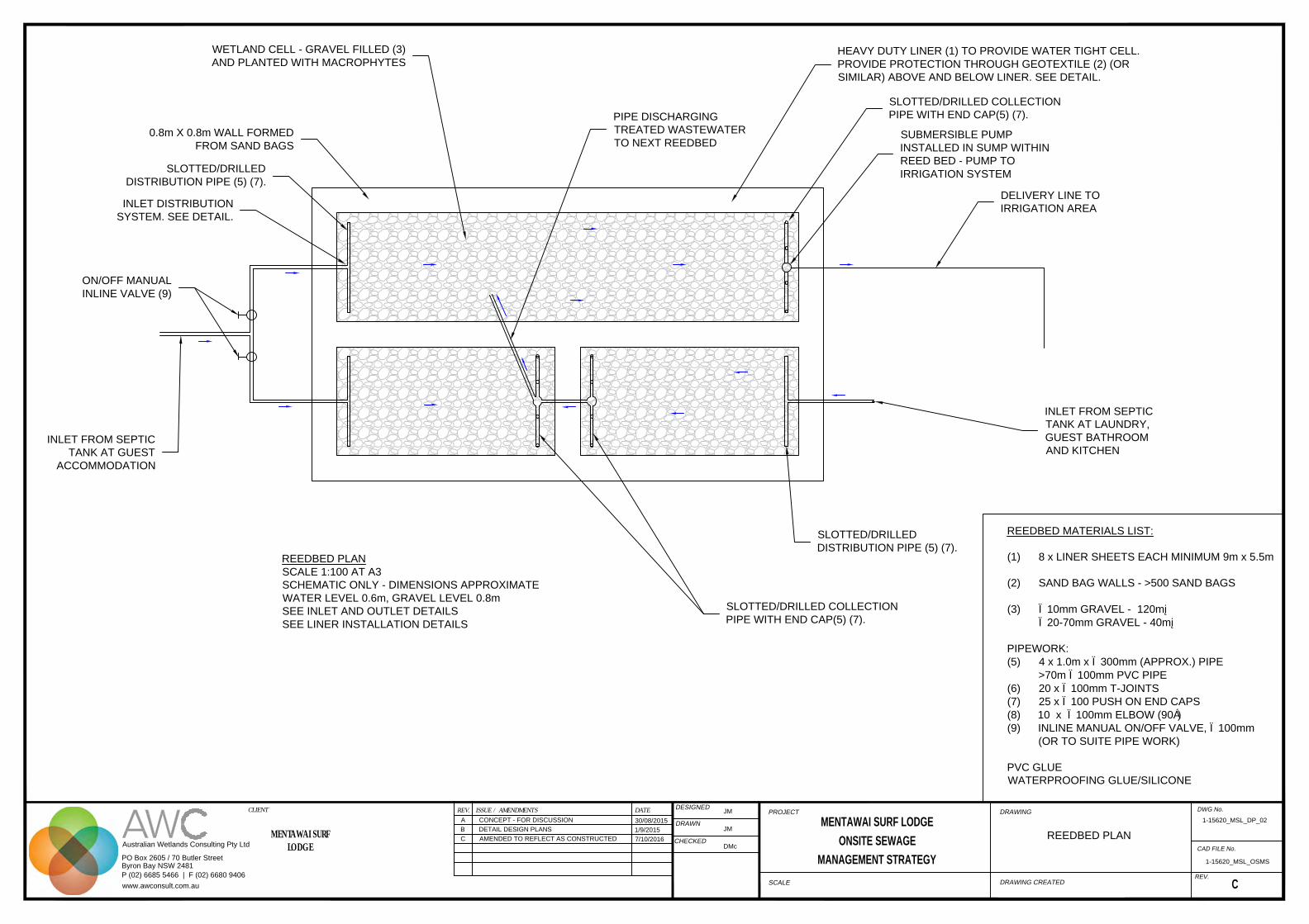
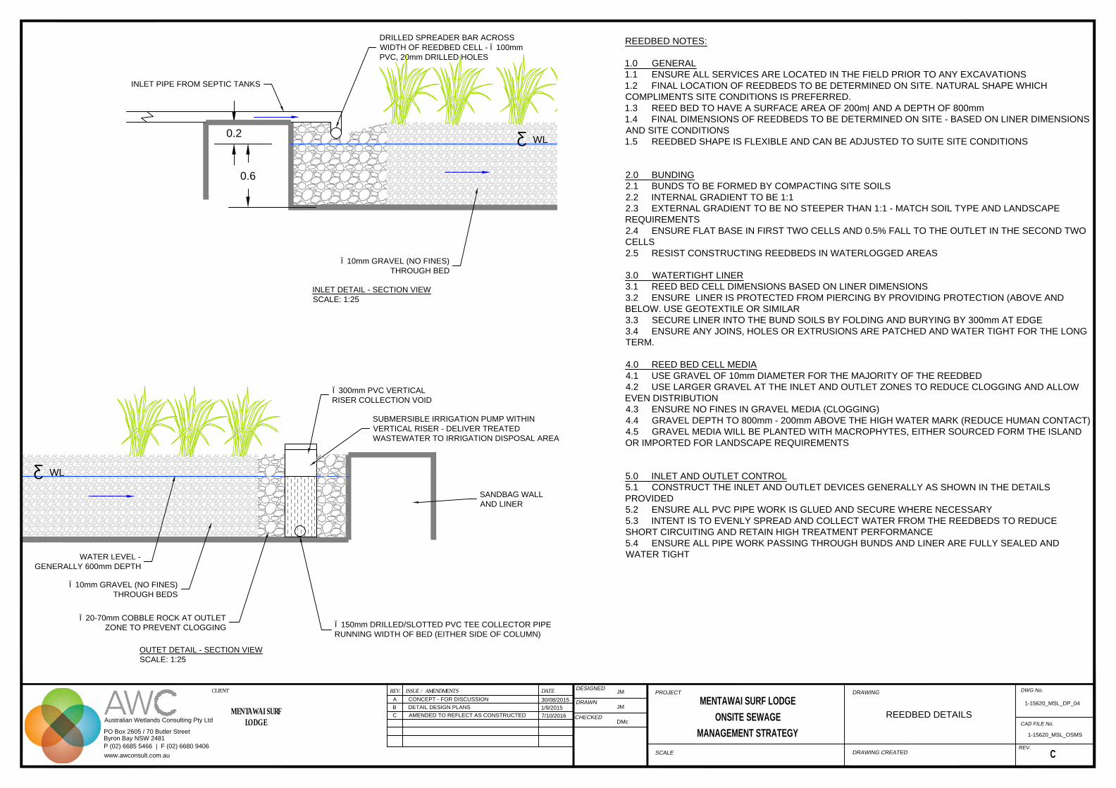
After primary treatment in the septic tanks all wastewater flow is directed to the reed bed system for further treatment. The reed bed system is known as a Horizontal Subsurface Flow wetland (HSSF). There are three main components of the reed beds, the inlet, the treatment area and the outlet, discussion provided below. Sheets 02, 03 and 04 of the design drawing set in Appendix A show reed bed detail.
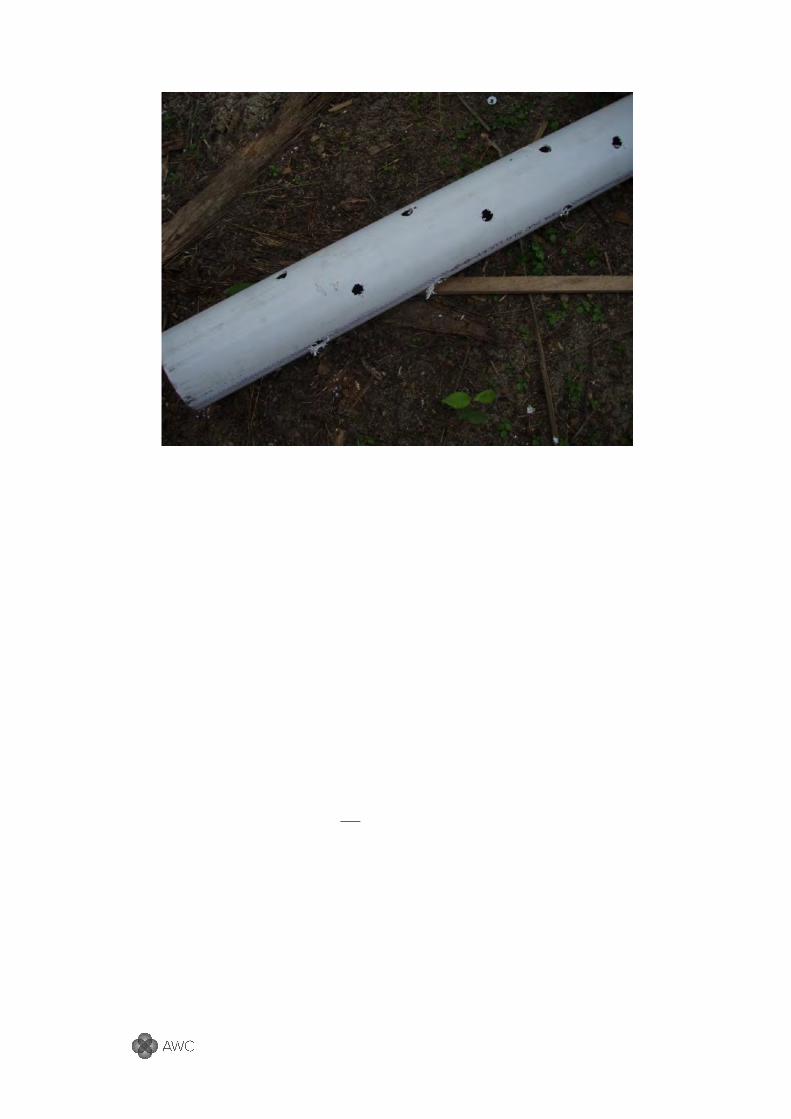
4.2.1 Inlet There are two reed bed systems that run in parallel. Wastewater is evenly distributed to each reed bed system through a T-joint in the delivery line from the septic tanks (refer Photo 1). On/off valves on each line allow isolation of each reed bed for maintenance or during system failure.
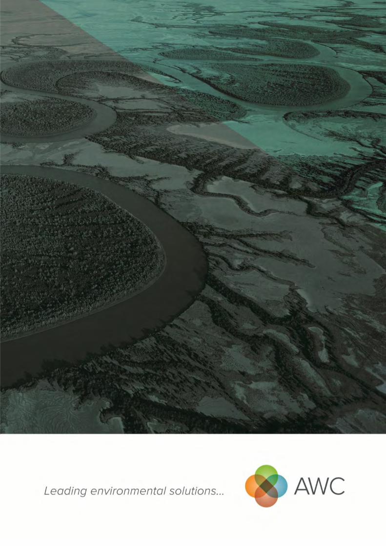
Wastewater, from the septic tanks, is delivered to one end of the reed beds through an inlet system that spreads the flow evenly across the width of the bed. This is simply drilled PVC pipe set level (refer Photo 2).
Photo 1. T-joint and on/off valves on the inlet delivery line from the septic tanks to the reed beds
Gin Gin Mentawai Surf Lodge – Sewage Management Strategy
Australian Wetlands Consulting Pty Ltd | Project # 1-15620_1b 10
Photo 2. Example of drilled pipe used on the inlet delivery system
4.2.2 Treatment Area (Reed Bed)
The reed beds are formed by the construction of a water tight container which is filled with a media that allows growth of macrophytes (water loving plants). Macrophytes absorb and remove some pollutants, particularly nutrients, they also absorb and transpire water. Algae and bacteria also live on the media and form what is known as biofilm. Biofilm performs treatment through biochemical reactions.
The reed bed cells have been constructed from heavy duty tarps, double layer, laid over sand bag walls (refer Photo 3). The water depth is approximately 600mm however the total depth is 800mm. This ensures the wastewater is below the surface of the media, reducing human contact.
The media within the reed bed treatment area is gravel, in the case of this reed bed, coral fragments have been used (refer Photo 4). The coral fragments were sourced from a supplier in the region.
The reed beds are densely planted with wetland plants found within the lodge. Plants with soft roots have been used to avoid puncturing the liner. If one plant type is not growing well, it should be replaced with another species.
Note: Plant harvesting is not necessary to maintain the health of the reed bed

Gin Gin Mentawai Surf Lodge – Sewage Management Strategy
Australian Wetlands Consulting Pty Ltd | Project # 1-15620_1b 11
Photo 3. Reed bed cell. Note the heavy duty tarp used for water tight cell.
Photo 4. Coral fragments used for the reed bed treatment media.
4.2.3 Outlet The outlet system collects water from one reed bed cell after treatment and discharges to the next reed bed cell. At the last reed bed there is a pump sump set into the reed bed. A primary aim is to collect water from the width of the reed bed cell and also from a variety of depths. It is important that wastewater passes through the media evenly and does not short circuit, allowing the highest treatment.
A series of slotted or drilled PVC vertical riser pipes collect treated wastewater and delivers to a main collection well in the reed bed made from 300mm PVC pipe.
Gin Gin Mentawai Surf Lodge – Sewage Management Strategy
Australian Wetlands Consulting Pty Ltd | Project # 1-15620_1b 12
Photo 5. Outlet collection system. Note slotted main collection chamber using 300mm PVC pipe.
Photo 6. Drilled and slotted collection pipes. Capped risers.
4.2.4 Modelling A pollutant reduction model has been set up using the wastewater characterisation values (refer Section 3). This model adopted an influent TN concentration of 50mg/L, BOD of 140mg/L and TP of 12mg/L based on values provided in Kadlec & Wallace (2009). Other influent concentrations are shown in Table 4-2. As a conservative measure, the climatic inputs are based on dry season values with the resort under full occupancy. These figures have been used to inform a daily pollutant reduction model involving two steps:

Gin Gin Mentawai Surf Lodge – Sewage Management Strategy
Australian Wetlands Consulting Pty Ltd | Project # 1-15620_1b 13
1. Hydraulic modelling of flow into, through and out of proposed treatment wetland 2. Pollutant reduction as it travels through the proposed treatment reed bed
The hydraulic modelling of flow into, through and out of proposed treatment reed bed will involve the basic water budget conducted in a series of tanks model (TIS Model), see Figure 4-2. For subsurface flow reed beds, it is common practice to use a TIS Model with three tanks (Kadlec and Wallace, 2009). Pollutant reduction modelling is then undertaken on each ‘tank’, with the first order pollutant reduction model k-C* (Kadlec and Wallace, 2009) (See Equation 1).
Figure 4-2. The Tank – in – series (TIS) model for wetland hydraulics and contaminant removal. Taken from Kadlec and Wallace (2009)
����∗
����∗= exp �−
��
���� Equation 1
&
�� = ���. (�)����
Where; Co = Pollutant outlet concentration, mg/L C* = wetland pollutant background concentration, mg/L Kt = pollutant areal rate constant at temperature T, m/day K20 = pollutant areal rate constant at 20oC, m/day Ci = polluant inlet concentration, mg/L HLR = Annual influent flow rate, m/day Θ = temperature coefficient
Basic design characteristics of the treatment wetlands are displayed in Table 4-1. Modelling was undertaken based on the peak occupancy of the Lodge during the dry season.

Gin Gin Mentawai Surf Lodge – Sewage Management Strategy
Australian Wetlands Consulting Pty Ltd | Project # 1-15620_1b 14
Table 4-1 Trial treatment wetland input values and modelling information
Wetland characteristics
Unit Value
Wetland size ha 0.02 (200m²)
Wetland porosity % 40%
Bed Depth m 0.6
Dry season operating temperature
oC 31.0
Precipitation - daily
0.89cm Mean daily rainfall divided by number of rain days during dry season (July) (refer Section2.2)
Evaporation - daily 0.45cm
Pollutant reduction modelling specifics
Unit SS BOD5 TP TN FC
(cfu/100mL) Wetland Background Limit, C*
mg/L 5.0 5.0 0.02 1.0 930
Areal Rate Constant, 20°C, k20
m/y 10000 44 10 11.2 201
Temperature Factor q 1.0 1.0 1.05 1.050 1.0
Areal Rate Constant m/y 10000 44 10 19 201
Modelling results show a substantial reduction in pollutants resulting from the treatment reedbed. Table 4-2 shows influent and effluent concentrations as well as the percentage reduction values based on concentration.
There is a reduction of 90% and 86% of TSS and BOD values. This is important as suspended solids can cause blockage and failure of the irrigation area, so low concentrations in these values are vital for the longevity of the disposal field performance.
TP reduction of 53% is adequate, although in realty may be higher based on the calcium in the coral used as the reed bed media. Calcium adsorbs and binds phosphorous molecules providing a removal pathway from the wastewater stream.
A 70% reduction in nitrogen is achieved. Further reductions will occur as biochemical reactions within the land application area as well as uptake from plants in the irrigation area.
Table 4-2 Pollutant reduction modelling results
unit SS BOD TP TN FC Influent concentration mg/L 50 140 12 50 930
Effluent concentration mg/L 5 19.1 5.7 15.2 4.4
reduction (based on concentration) % 90% 86% 53% 70% 90%

Gin Gin Mentawai Surf Lodge – Sewage Management Strategy
Australian Wetlands Consulting Pty Ltd | Project # 1-15620_1b 15
4.3 Disposal
Land application or irrigation of treated wastewater for beneficial use is the key aim of the disposal system. Treated wastewater is pumped from the collection tank at the reed beds to a subsurface irrigation area that is planted with fruit trees and other species that are used at the Lodge either for a range of purposes.
Design of the irrigation system was to provide a system that was simple, easily modified and maintained. Sheets 05 and 06 of the design drawings in Appendix A show the disposal area details. As disinfection was not practical, irrigation is discharged below ground surface to limit human contact.
The disposal area is a total of 225m². This has been calculated on a peak loading rate of 7200L/day (refer Section 3.1) and a Design Loading Rate (DLR) of 32mm/day. The DLR is sourced from AS1547:2012 for sand soil types.
Disposal Area (m²) = Daily Peak Load (L) / DLR = 7200L / 32mmp.day = 225m²
The layout of the irrigation area was finalised on site; it is 5m wide and 45m in length and is located between the beach front and the row of detached bungalows. There are five lateral runs of 45m in length.
Each lateral consists of a Ø75mm PVC pipe with Ø10mm holes drilled in the lower half. Within each of the drilled PVC pipes is Ø35mm HDPE poly pipe with 5mm holes drilled every two metres. Each lateral shall have an on/off valve to isolate and rest lines alternately. The PVC pipes are laid level with the holes ensured at the base of the pipe. If the holes are not at the bottom there is the potential the sandy soils will migrate into the PVC pipe reducing the void space and/or blocking the pipe. The PVC pipe forms a void space that will partially fill with pumped treated wastewater and percolate into the soils beneath. The PVC pipe is buried just below the ground surface.
The pump (Grundfos Unilift KP A 250) will be set to deliver doses of approximately 750L to the irrigation field. A float switch will engage the pump when the water level reaches a pre-determined level in the pump tank.

Gin Gin Mentawai Surf Lodge – Sewage Management Strategy
Australian Wetlands Consulting Pty Ltd | Project # 1-15620_1b 16
5 Maintenance and Monitoring
It is recommended that the system be inspected weekly by maintenance staff to ensure there is no obvious failure of the system (i.e. sewage overflow). Additionally a more thorough inspection should be undertaken every three months, a checklist for management of the system is provided in Appendix B which should be filled out and filed.
5.1 General
The following is recommended with regard to the usage of the OSMS to maintain treatment capacity, increased quality of treated wastewater, prolong the life of the system, diagnose any problems and reduce potential overflow/blockage:
Use low phosphorous and sodium detergents. Heavy sodium application to soils can cause the structure to collapse and substantially reduce the infiltration capacity of the disposal area
Minimise or avoid high toxicity detergents and cleaning products entering the system
Do not dispose of large quantities of chemicals, paints, fuels, medicines or any other similar substances into the system
Do not allow solid objects such as tampons, nappies or condoms, chip packets etc to enter the system. Provide bins at strategic locations to reduce the potential of these items entering the system
Restrict access to the disposal field, minimise pedestrian and vehicular access where possible
Lodge management should undertake regular (weekly) inspections of the system to ensure any potential problems are detected early and corrected. The following are typical indications of system failure:
Water surfacing within reedbeds, pump tank, disposal field, septic tanks or along the pipe lines
Poor or uneven vegetation growth in disposal field
Unusually noxious odours emanating from drains, septic tank or disposal area
Slow draining or gurgling toilets or drainage points (sinks)
5.2 Septic Tanks
Weekly inspections will ensure septic tanks are not overflowing. More thorough (quarterly) inspections will check there is no floating debris within the tank Over time sludge and crust in the tank will build up to levels where treatment is reduced
and will need to be removed, approximately every 3-5 years. At this time the tank will require emptying, with the most appropriate disposal option being to bury in garden beds

Gin Gin Mentawai Surf Lodge – Sewage Management Strategy
Australian Wetlands Consulting Pty Ltd | Project # 1-15620_1b 17
within the lodge.
Note: No plastics should be placed in drains or toilets, as these will block pipes.
5.3 Reed Beds
An even flow through each reed bed cell is important to ensure there are no short circuit pathways which cause decreased treatment performance. Even distribution and collection with the designed inlet and out collection systems is therefore important.
Blockage of the inlets and outlet can occur through roots growing into the pipework. All pipe work needs to be regularly checked to ensure this is not occurring; this can be done using the vertical standpipes.
The outlet pipe should be the only place where treated water discharges. If there is water exiting the reed bed anywhere else these leakages will need fixing.
There should not be any surface water visible in the reed bed. If water is visible, the reed bed water level may need to be lowered, or additional aggregate placed in the area. Blockages can cause increased water levels – check for and clear any blockages.
The reed beds should have dense plant cover (>80%). Use a mix of species sourced from the local area. If a particular species of plant is not growing well, remove it and replace with a different species. Do not plant large woody (tree) species or species with strong roots.
Ensure all treated wastewater flows to the collection and pump well and there is no overflow over the sides of the reed bed.
5.4 Disposal Area
The main aim of the disposal field is to distribute the treated wastewater over the area as evenly as possible. Further treatment (through fine filtration and biochemical reactions) will occur as it percolates through the soil. As there is no disinfection, it is important that there is no surface water.
Maintenance and monitoring will focus on the functioning of the pump and distribution. Routine inspections will look for any obvious surface water and pump testing. If water is pooling in depressions, the depression is to be filled in with friable soils from the site.
Vegetation in the irrigation disposal area also aids treatment through uptake of water and remaining nutrients in the treated wastewater. Healthy vegetation does this best, so maintenance and monitoring of the vegetation is important. Any diseased plants should be removed and replaced.
The irrigation area should be checked weekly to ensure there are no blockages or leaks.

Gin Gin Mentawai Surf Lodge – Sewage Management Strategy
Australian Wetlands Consulting Pty Ltd | Project # 1-15620_1b 18
5.5 Maintenance Schedule
A detailed inspection checklist is provided in Appendix B. Table 5-1 is a summary of monitoring and working maintenance required. Ongoing and frequent monitoring and reactive and preventative works will maximise the treatment efficiency, reducing potential environmental impact and extend the life of the system.
Table 5-1 Regular maintenance tasks
Task Frequency Check the inlet of the three reedbed cells. Ensure no blockage and flowing freely.
Weekly
Check the outlet of the top two reedbed cells. Ensure no blockage and flowing freely.
weekly
Ensure there is no water on the reed beds. If there is check for blockages and/or run pump.
Daily
Check water level in outlet sump of reedbed three (last one).
Turn pump on when water level above pump
Run pump for 30 minutes Do not let the pump run dry Before pump is turned on, ensure one
irrigation line is on and two is off (on/off valves on each line) – change irrigation lines each time the pump is turned on to distribute water evenly
Daily
Ensure one inlet valve is open the other one is shut. Swap over every two weeks or at the start of each surf camp
every two weeks or at the start of each surf camp
Do not cut plants or pullout plants in the reed bed cells. If plants die plant more.
Ongoing
Irrigation area Keep main on/off valve on Before pump is turned on, ensure one
irrigation line is on and two is off (on/off valves on each line)
change irrigation lines each time the pump is turned on to distribute water evenly
Daily

Gin Gin Mentawai Surf Lodge – Sewage Management Strategy
Australian Wetlands Consulting Pty Ltd | Project # 1-15620_1b 19
6 References
Department of Land and Water Conservation, NSW (1998) The Constructed Wetlands Manual, Volumes 1 & 2.
Crites, R. and Tchobanoglous, G. (1998) Small and Decentralized Wastewater Management Systems. McGraw Hill, U.S.A.
Kadlec, R. H. and Tilton, D.L. (1979) The use of freshwater wetlands as a tertiary wastewater treatment alternative. CRC Critical Reviews in Environmental Control 9(2): 185-212.
Kadlec, R. H. and Wallace, S.D. (2009) Treatment Wetlands (2nd Ed.) Taylor and Francis Group, Boca Raton, USA.
National Resource Ministerial Council (NRMC), Environment Protection and Heritage Council (EPHC) & Australian Health Ministers Conference (AHMC) (2006) National Water Quality Management Strategy National guidelines for water recycling: managing health and environmental risks (Phase 1) [Online] Accessed 17 April 2012 from http://www.ephc.gov.au/taxonomy/term/39

Gin Gin Mentawai Surf Lodge – Sewage Management Strategy
Australian Wetlands Consulting Pty Ltd | Project # 1-15620_1b 20
Appendix A
Design Plans

IRRIGATION
PUMP
SEPARATION DISTANCE
FROM WATER WELLS TO
SEWAGE DISPOSAL AREAS
TREATED
WASTEWATER
DISPOSAL -
IRRIGATION
AREA
DWG No.
CAD FILE No.
REV.
PROJECT DRAWING
SCALEDRAWING CREATED
REV. DATEISSUE / AMENDMENTS
DESIGNED
DRAWN
CHECKED
CLIENT
MENTAWAI SURF LODGE
ONSITE SEWAGE
MANAGEMENT STRATEGY
Australian Wetlands Consulting Pty Ltd
PO Box 2605 / 70 Butler Street
Byron Bay NSW 2481
P (02) 6685 5466 | F (02) 6680 9406
www.awconsult.com.au
MENTAWAI SURFLODGE
A CONCEPT - FOR DISCUSSION
30/08/2015
JM
JM
1-15620_MSL_OSMS
C
B DETAIL DESIGN PLANS1/9/2015
DMc
C AMENDED TO REFLECT AS CONSTRUCTED7/10/2016 CONCEPT OSMS PLAN
1-15620_MSL_CP_01
INLET DISTRIBUTION
SYSTEM. SEE DETAIL.
WETLAND CELL - GRAVEL FILLED (3)
AND PLANTED WITH MACROPHYTES
0.8m X 0.8m WALL FORMED
FROM SAND BAGS
HEAVY DUTY LINER (1) TO PROVIDE WATER TIGHT CELL.
PROVIDE PROTECTION THROUGH GEOTEXTILE (2) (OR
SIMILAR) ABOVE AND BELOW LINER. SEE DETAIL.
REEDBED PLAN
SCALE 1:100 AT A3
SCHEMATIC ONLY - DIMENSIONS APPROXIMATE
WATER LEVEL 0.6m, GRAVEL LEVEL 0.8m
SEE INLET AND OUTLET DETAILS
SEE LINER INSTALLATION DETAILS
SUBMERSIBLE PUMP
INSTALLED IN SUMP WITHIN
REED BED - PUMP TO
IRRIGATION SYSTEM
SLOTTED/DRILLED
DISTRIBUTION PIPE (5) (7).
PIPE DISCHARGING
TREATED WASTEWATER
TO NEXT REEDBED
SLOTTED/DRILLED
DISTRIBUTION PIPE (5) (7).
SLOTTED/DRILLED COLLECTION
PIPE WITH END CAP(5) (7).
ON/OFF MANUAL
INLINE VALVE (9)
INLET FROM SEPTIC
TANK AT GUEST
ACCOMMODATION
INLET FROM SEPTIC
TANK AT LAUNDRY,
GUEST BATHROOM
AND KITCHEN
SLOTTED/DRILLED COLLECTION
PIPE WITH END CAP(5) (7).
DELIVERY LINE TO
IRRIGATION AREA
DWG No.
CAD FILE No.
REV.
PROJECT DRAWING
SCALEDRAWING CREATED
REV. DATEISSUE / AMENDMENTS
DESIGNED
DRAWN
CHECKED
CLIENT
MENTAWAI SURF LODGE
ONSITE SEWAGE
MANAGEMENT STRATEGY
Australian Wetlands Consulting Pty Ltd
PO Box 2605 / 70 Butler Street
Byron Bay NSW 2481
P (02) 6685 5466 | F (02) 6680 9406
www.awconsult.com.au
MENTAWAI SURFLODGE
A CONCEPT - FOR DISCUSSION
30/08/2015
JM
JM
1-15620_MSL_OSMS
C
B DETAIL DESIGN PLANS1/9/2015
DMc
C AMENDED TO REFLECT AS CONSTRUCTED7/10/2016
REEDBED PLAN
1-15620_MSL_DP_02
REEDBED MATERIALS LIST:
(1) 8 x LINER SHEETS EACH MINIMUM 9m x 5.5m
(2) SAND BAG WALLS - >500 SAND BAGS
(3) Ø10mm GRAVEL - 120m³
Ø20-70mm GRAVEL - 40m³
PIPEWORK:
(5) 4 x 1.0m x Ø300mm (APPROX.) PIPE
>70m Ø100mm PVC PIPE
(6) 20 x Ø100mm T-JOINTS
(7) 25 x Ø100 PUSH ON END CAPS
(8) 10 x Ø100mm ELBOW (90°)
(9) INLINE MANUAL ON/OFF VALVE, Ø100mm
(OR TO SUITE PIPE WORK)
PVC GLUE
WATERPROOFING GLUE/SILICONE

7.0
0.8
0.6
0.8
Ø10mm GRAVEL (NO FINES)
THROUGH BOTH BEDS
OUTLET COLLECTION AND
DISCHARGE SYSTEM. SEE DETAIL
INLET DISTRIBUTION
SEE DETAIL
Ø20-70mm GRAVEL (NO FINES)
AROUND ALL INLET AND OUTLET
ZONES TO PREVENT CLOGGING
TYPICAL REEDBED LONG SECTION
SCALE 1:100 AT A3
WATER LEVEL 0.6m, GRAVEL LEVEL 0.8m
SEE INLET AND OUTLET DETAILS
SEE LINER INSTALLATION DETAILS
COLLECTION/PUMP WELL WITHIN VERTICAL PIPE OF LAST
REEDBED (SEE PLAN) SUBMERSIBLE PUMP TO DELIVER
TREATED WASTEWATER TO THE IRRIGATION AREA
PLANTED MACROPHYTES
▼WL
WALL FORMED FROM SANDBAGS -
APPROXIMATELY 0.9m HIGH X 0.8m WIDE
DOUBLE LAYER RUBBER
LINER - SEE DETAIL
5.1
3.5
0.8
0.6
0.8
PERFORATED
COLLECTION PIPE
OUTLET DISCHARGE PIPE
- THROUGH BUND WALL
20-70mm GRAVEL AT INLETS AND
OUTLETS TO PREVENT CLOGGING
SANDBAG WALLS -
SEE DETAIL
PLANTED MACROPHYTES
TYPICAL REEDBED CROSS SECTION
SCALE 1:100 AT A3
OUTLET HCOLLECTION SYSTEM DETAILED
WATER LEVEL 0.6m, GRAVEL LEVEL 0.8m
SEE INLET AND OUTLET DETAILS
SEE LINER INSTALLATION DETAILS
LINER DETAIL
SCALE: 1:40
PLACE GEOTEXTILE FABRIC (OR SIMILAR) ABOVE AND BENEATH HEAVY
DUTY LINER TO PROTECT FROM PIERCING
ENSURE LINER PROTECTION EXTENDS TO GRAVEL MEDIA DEPTH MINIMUM
ENSURE LINER IS WATERTIGHT - PATCH/GLUE ANY HOLES
SECURE EDGE OF LINER BY BURYING AND FOLDING MINIMUM 300mm
HEAVY DUTY LINER TO
FORM WATERTIGHT CELL
DOUBLE LAYER AND
LAPPED AT EDGE
REEDBED
GRAVEL MEDIA
WALL FORMED FROM
SANDBAGS - APPROXIMATELY
0.9m HIGH X 0.8m WIDE
0.8
0.8
0.6
WL
DWG No.
CAD FILE No.
REV.
PROJECT DRAWING
SCALEDRAWING CREATED
REV. DATEISSUE / AMENDMENTS
DESIGNED
DRAWN
CHECKED
CLIENT
MENTAWAI SURF LODGE
ONSITE SEWAGE
MANAGEMENT STRATEGY
Australian Wetlands Consulting Pty Ltd
PO Box 2605 / 70 Butler Street
Byron Bay NSW 2481
P (02) 6685 5466 | F (02) 6680 9406
www.awconsult.com.au
MENTAWAI SURFLODGE
A CONCEPT - FOR DISCUSSION
30/08/2015
JM
JM
1-15620_MSL_OSMS
C
B DETAIL DESIGN PLANS1/9/2015
DMc
C AMENDED TO REFLECT AS CONSTRUCTED7/10/2016
REEDBED DETAILS
1-15620_MSL_DP_03

1.00.3
0.1
EXISTING GROUND
SURFACE
MOUND SOIL DIMENSIONS, LOCATION AND
ALIGNMENT VARIABLE DEPENDING ON SITE
CONDITIONS - MINIMUM 0.3m DEPTH
FREE DRAINING SOIL - AVOID LOCATIONS WITH
STANDING WATER OR HIGH GROUNDWATER
PRESSURISED APPROX Ø32mm HDPE POLY PIPE (1)
WITH HOLES (5mm) DRILLED ALONG THE LENGTH -
LAID INSIDE PERFORATED PIPE
HOLE SIZE AND SPACING TO BE DETERMINED ON SITE
PLANT MOUND AND
SURROUNDING AREAS -
LANDSCAPE PLANTS AND MULCH
TYPICAL DISPOSAL BED
SECTION A-A
SCALE:1:10 AT A3
- BASED ON WISCONSIN MOUND SYSTEM - AS1547:2012
- PERFORATED PIPE IS TO BE LAID LEVEL TO ENSURE EVEN DISTRIBUTION THROUGH MOUND
- MOUND AND SURROUNDS ARE TO BE PLANTED - LANDSCAPING PLANTS SUITABLE, NO LARGE
TREES ON THE MOUND
- EXISTING GROUND SURFACE TO BE RIPPED OR ENSURE PERMEABLE - SANDY SOILS
DRILLED Ø75-100mm
PVC PIPE (3)
1.0
Ø75-100mm PVC PIPE
HOLES DRILLED AS SHOWN
10mm HOLES DRILLED IN
LOWER HALF OF PIPE ONLY
DRILLED IRRIGATION LATERALS - Ø32mm HDPE
5mm DRILL HOLE DIAMETER, DRILL HOLE
SPACING TO BE DETERMINED ON SITE
PVC PIPE TO
BE LAID LEVEL
IRRIGATION DETAIL
SCALE: 1:10
10mm HOLES TO BE DRILLED IN LOWER HALF ONLY OF THE PVC PIPE
PVC PIPE TO BE LAID LEVEL
IRRIGATION LATERAL Ø32mm HDPE POLY PIPE - HOLES 5mm SPACING
TO BE DETERMINED ON SITE
DWG No.
CAD FILE No.
REV.
PROJECT DRAWING
SCALEDRAWING CREATED
REV. DATEISSUE / AMENDMENTS
DESIGNED
DRAWN
CHECKED
CLIENT
MENTAWAI SURF LODGE
ONSITE SEWAGE
MANAGEMENT STRATEGY
Australian Wetlands Consulting Pty Ltd
PO Box 2605 / 70 Butler Street
Byron Bay NSW 2481
P (02) 6685 5466 | F (02) 6680 9406
www.awconsult.com.au
MENTAWAI SURFLODGE
A CONCEPT - FOR DISCUSSION
30/08/2015
JM
JM
1-15620_MSL_OSMS
C
B DETAIL DESIGN PLANS1/9/2015
DMc
C AMENDED TO REFLECT AS CONSTRUCTED7/10/2016 DISPOSAL SYSTEM
1-15620_MSL_DP_05
DISPOSAL NOTES:
1. TOTAL DISPOSAL AREA REQUIRED IS 225m². THIS
SHALL BE MADE UP OF A PRESSURISED IRRIGATION
SYSTEM MODIFIED TO SUIT SITE CONDITIONS (IE FRUIT
TREES).
2. IRRIGATION AREA TO BE 10 x 22.5m LONG LATERAL
PIPES (SEE DETAIL) AT 1.0M SPACING. OR OTHERWISE
SET OUT ON SITE TO BEST CONDITIONS.
3. IRRIGATION AREA FOR DISPOSAL WILL HAVE
DRILLED Ø32mm POLY PIPE (OR SIMILAR) SET WITHIN A
DRILLED PVC PIPE FOR EVEN AND THOROUGH
DISTRIBUTION. THE PERFORATED PIPE ALLOWS SOME
STORAGE AND REDUCES THE LIKELIHOOD OF ROOT AND
SOIL INGRESS INTO THE IRRIGATION LINE.
4. PERORATED PIPE SHALL BE LAID LEVEL TO ENSURE
EVEN DISTRIBUTION ALONG THE LENGTH. WATER WILL
NATURALLY DRAIN TO LOW POINTS PROVIDING UNEVEN
DISTRIBUTION.
5. FINAL LOCATIONS, DIMENSIONS, SET OUT AND
PLANT SPECIES TO BE DETERMINED ON SITE.
MATERIALS LIST:
NOTE: AS LOCATIONS, DIMENSIONS, SET OUT, ALIGNMENT AND
OTHER DETAILS ARE NOT KNOWN THE MATERIALS LIST IS
PRELIMINARY ONLY AND IS BOUND TO CHANGE AT ON-SITE SET OUT.
PIPEWORK:
(1) 225m x Ø32mm POLY PIPE LATERALS (TO BE DRILLED ON SITE)
(2) 50m x Ø32mm POLY PIPE FOR DELIVERY - ASSUMED LENGTH
(3) 225m x Ø75-100mm PERFORATED PIPE (AG PIPE)
FITTINGS:
TO FIT Ø32mm HDPE POLY PIPE DELIVERY LINE AND LATERALS
ASSUME 10 LATERALS AT 22.5m LENGTH EACH
(4) 5 x MANUAL IN LINE TAP
20 x JOINER
25 x T-JOINT
20 x 90° ELBOW
20 x END STOPS
CLIPS
0.2
DRILLED SPREADER BAR ACROSS
WIDTH OF REEDBED CELL - Ø100mm
PVC, 20mm DRILLED HOLES
Ø10mm GRAVEL (NO FINES)
THROUGH BED
INLET PIPE FROM SEPTIC TANKS
0.6
INLET DETAIL - SECTION VIEW
SCALE: 1:25
▼WL
Ø10mm GRAVEL (NO FINES)
THROUGH BEDS
SUBMERSIBLE IRRIGATION PUMP WITHIN
VERTICAL RISER - DELIVER TREATED
WASTEWATER TO IRRIGATION DISPOSAL AREA
Ø20-70mm COBBLE ROCK AT OUTLET
ZONE TO PREVENT CLOGGING
OUTET DETAIL - SECTION VIEW
SCALE: 1:25
Ø150mm DRILLED/SLOTTED PVC TEE COLLECTOR PIPE
RUNNING WIDTH OF BED (EITHER SIDE OF COLUMN)
WATER LEVEL -
GENERALLY 600mm DEPTH
▼WL
Ø300mm PVC VERTICAL
RISER COLLECTION VOID
SANDBAG WALL
AND LINER
DWG No.
CAD FILE No.
REV.
PROJECT DRAWING
SCALEDRAWING CREATED
REV. DATEISSUE / AMENDMENTS
DESIGNED
DRAWN
CHECKED
CLIENT
MENTAWAI SURF LODGE
ONSITE SEWAGE
MANAGEMENT STRATEGY
Australian Wetlands Consulting Pty Ltd
PO Box 2605 / 70 Butler Street
Byron Bay NSW 2481
P (02) 6685 5466 | F (02) 6680 9406
www.awconsult.com.au
MENTAWAI SURFLODGE
A CONCEPT - FOR DISCUSSION
30/08/2015
JM
JM
1-15620_MSL_OSMS
C
B DETAIL DESIGN PLANS1/9/2015
DMc
C AMENDED TO REFLECT AS CONSTRUCTED7/10/2016 REEDBED DETAILS
1-15620_MSL_DP_04
REEDBED NOTES:
1.0 GENERAL
1.1 ENSURE ALL SERVICES ARE LOCATED IN THE FIELD PRIOR TO ANY EXCAVATIONS
1.2 FINAL LOCATION OF REEDBEDS TO BE DETERMINED ON SITE. NATURAL SHAPE WHICH
COMPLIMENTS SITE CONDITIONS IS PREFERRED.
1.3 REED BED TO HAVE A SURFACE AREA OF 200m² AND A DEPTH OF 800mm
1.4 FINAL DIMENSIONS OF REEDBEDS TO BE DETERMINED ON SITE - BASED ON LINER DIMENSIONS
AND SITE CONDITIONS
1.5 REEDBED SHAPE IS FLEXIBLE AND CAN BE ADJUSTED TO SUITE SITE CONDITIONS
2.0 BUNDING
2.1 BUNDS TO BE FORMED BY COMPACTING SITE SOILS
2.2 INTERNAL GRADIENT TO BE 1:1
2.3 EXTERNAL GRADIENT TO BE NO STEEPER THAN 1:1 - MATCH SOIL TYPE AND LANDSCAPE
REQUIREMENTS
2.4 ENSURE FLAT BASE IN FIRST TWO CELLS AND 0.5% FALL TO THE OUTLET IN THE SECOND TWO
CELLS
2.5 RESIST CONSTRUCTING REEDBEDS IN WATERLOGGED AREAS
3.0 WATERTIGHT LINER
3.1 REED BED CELL DIMENSIONS BASED ON LINER DIMENSIONS
3.2 ENSURE LINER IS PROTECTED FROM PIERCING BY PROVIDING PROTECTION (ABOVE AND
BELOW. USE GEOTEXTILE OR SIMILAR
3.3 SECURE LINER INTO THE BUND SOILS BY FOLDING AND BURYING BY 300mm AT EDGE
3.4 ENSURE ANY JOINS, HOLES OR EXTRUSIONS ARE PATCHED AND WATER TIGHT FOR THE LONG
TERM.
4.0 REED BED CELL MEDIA
4.1 USE GRAVEL OF 10mm DIAMETER FOR THE MAJORITY OF THE REEDBED
4.2 USE LARGER GRAVEL AT THE INLET AND OUTLET ZONES TO REDUCE CLOGGING AND ALLOW
EVEN DISTRIBUTION
4.3 ENSURE NO FINES IN GRAVEL MEDIA (CLOGGING)
4.4 GRAVEL DEPTH TO 800mm - 200mm ABOVE THE HIGH WATER MARK (REDUCE HUMAN CONTACT)
4.5 GRAVEL MEDIA WILL BE PLANTED WITH MACROPHYTES, EITHER SOURCED FORM THE ISLAND
OR IMPORTED FOR LANDSCAPE REQUIREMENTS
5.0 INLET AND OUTLET CONTROL
5.1 CONSTRUCT THE INLET AND OUTLET DEVICES GENERALLY AS SHOWN IN THE DETAILS
PROVIDED
5.2 ENSURE ALL PVC PIPE WORK IS GLUED AND SECURE WHERE NECESSARY
5.3 INTENT IS TO EVENLY SPREAD AND COLLECT WATER FROM THE REEDBEDS TO REDUCE
SHORT CIRCUITING AND RETAIN HIGH TREATMENT PERFORMANCE
5.4 ENSURE ALL PIPE WORK PASSING THROUGH BUNDS AND LINER ARE FULLY SEALED AND
WATER TIGHT

45.0
4.0
MANUAL TAP (4)
(ON/OFF) FOR
FLUSHING
DISTRIBUTION PIPE, Ø32mm POLY PIPE WITH HOLES DRILLED
ALONG THE LENGTH (SIZE AND SPACING TO BE DETERMINED)
LAID WITHIN DRILLED Ø75-100mm PVC PIPE
MOUNDED FREE DRAINAGE
SOIL - MINIMUM 0.3m
HIGH/DEPTH ABOVE EXISTING
SURFACE LEVEL
MOUND AND
SURROUNDS PLANTED
TYPICAL DISPOSAL BED
PLAN VIEW
SCALE 1:100 AT A3
BASED ON WISCONSIN MOUND SYSTEM- AS1547:2012
A
A
DELIVERY LINE TO LOW
POINT OF IRRIGATION AREA
DELIVERY LINE, HDPE Ø32mm POLY PIPE SUITABLE
FOR PRESSURISED (PUMPED) SYSTEM
FROM REEDBED COLLECTION/PUMP WELL
MANUAL VALVE/TAP
(ON/OFF) ON EACH LINE
FOR ALTERNATE SHUT OFF
DWG No.
CAD FILE No.
REV.
PROJECT DRAWING
SCALEDRAWING CREATED
REV. DATEISSUE / AMENDMENTS
DESIGNED
DRAWN
CHECKED
CLIENT
MENTAWAI SURF LODGE
ONSITE SEWAGE
MANAGEMENT STRATEGY
Australian Wetlands Consulting Pty Ltd
PO Box 2605 / 70 Butler Street
Byron Bay NSW 2481
P (02) 6685 5466 | F (02) 6680 9406
www.awconsult.com.au
MENTAWAI SURFLODGE
A CONCEPT - FOR DISCUSSION
30/08/2015
JM
JM
1-15620_MSL_OSMS
C
B DETAIL DESIGN PLANS1/9/2015
DMc
C AMENDED TO REFLECT AS CONSTRUCTED7/10/2016 DISPOSAL SYSTEM
1-15620_MSL_DP_06

Gin Gin Mentawai Surf Lodge – Sewage Management Strategy
Australian Wetlands Consulting Pty Ltd | Project # 1-15620_1b 21
Appendix B
Monitoring and Maintenance Checklists
OSMS Maintenance and Reporting Checklist Weekly Routine Inspection Gin Gins Mentawai Surf Lodge Inspection by: Date: Previous weather conditions: Question Comment Septic tanks. Inspect all septic tanks on site. Any noxious odours apparent?
Access adequate?
Any sewage overflows?
Is the outlet filter fitted and
functioning?
Reed Beds Is there any particularly foul
odours emanating from the Reed
beds?
Is there any apparent surface
water?
Is the inlet flowing freely?
Is there any vegetation at or near
the inlet distribution pipes that
may be blocking the pipes?
Check inspection opening at the
outlet– water levels? Any root
intrusion into the inspection
pipes?
Are the sand bag walls forming
the reedbeds stable? Any sign of
movement (sideways or sinking) or
structural failure?

Gin Gin Mentawai Surf Lodge – Sewage Management Strategy
Australian Wetlands Consulting Pty Ltd | Project # 1-15620_1b 22
Is the outlet clear and freely
flowing?
Is there any vegetation dieback or
health problems?
Is there any leakage visible
anywhere?
Check the on/off valves are
functional.
Is there overflow of the
collection/pump tank?
Check the pump is functional. Trip
the pump by lifting the float valve.
Other comments?
Disposal Area Is there any surface water?
Observe the disposal area while
pump is running.
Is there any spray obvious?
Is there any water flowing
onto the ground surface?
Are all visible joints water tight?
Is there any plant dieback?
Other comments?

Gin Gin Mentawai Surf Lodge – Sewage Management Strategy