
Getting started with ZERO - hspshop.it
20
Getting started with .ZERO Before you start. The AA-30.ZERO is intended for users who require flexibility, low-cost, and small size. It comes without on-board USB or pin headers to keep the cost down. It is the best choice for a measuring core you want to leave embedded in a project. Please note that the AA-30.ZERO operates at 5V (like most Arduino or Arduino compatible boards). Be sure to provide the correct power and use components/adaptors whose operating voltage matches the AA-30.ZERO. Connecting the AA-30.ZERO to your PC The AA-30.ZERO comes without a built-in USB circuitry, so an off-board USB to UART-TTL serial converter should be used to communicate with the analyzer. The AA-30.ZERO can communicate with other devices through any of two built-in UART interfaces: UART1 (pins 0/TX1 and 2/RX1) and UART2 (pins 4/TX2 and 7/RX2). By default, UART2 is used. To make our first project, we could get, for example, the SparkFun USB UART Serial Breakout. The USB2UART adapter is connected to the AA-30.ZERO by using colored wires.
Transcript of Getting started with ZERO - hspshop.it
Getting started with .ZERO Before you start. The AA-30.ZERO is intended for users who require flexibility, low-cost, and small size. It comes without on-board USB or pin headers to keep the cost down. It is the best choice for a measuring core you want to leave embedded in a project.
Please note that the AA-30.ZERO operates at 5V (like most Arduino or Arduino compatible boards). Be sure to provide the correct power and use components/adaptors whose operating voltage matches the AA-30.ZERO. Connecting the AA-30.ZERO to your PC The AA-30.ZERO comes without a built-in USB circuitry, so an off-board USB to UART-TTL serial converter should be used to communicate with the analyzer.
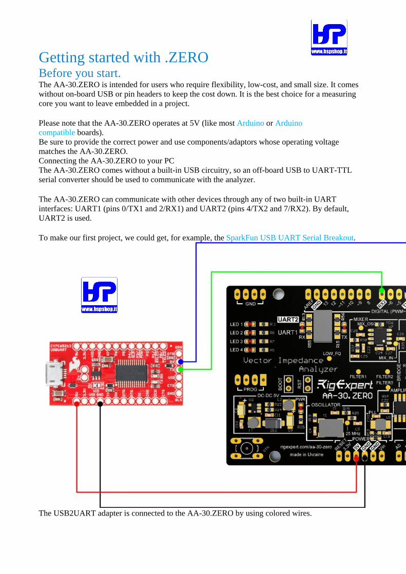
The AA-30.ZERO can communicate with other devices through any of two built-in UART interfaces: UART1 (pins 0/TX1 and 2/RX1) and UART2 (pins 4/TX2 and 7/RX2). By default, UART2 is used.
To make our first project, we could get, for example, the SparkFun USB UART Serial Breakout.
The USB2UART adapter is connected to the AA-30.ZERO by using colored wires.
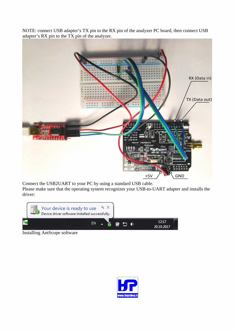
NOTE: connect USB adapter’s TX pin to the RX pin of the analyzer PC board, then connect USB adapter’s RX pin to the TX pin of the analyzer.
Connect the USB2UART to your PC by using a standard USB cable. Please make sure that the operating system recognizes your USB-to-UART adapter and installs the driver:
Installing AntScope software
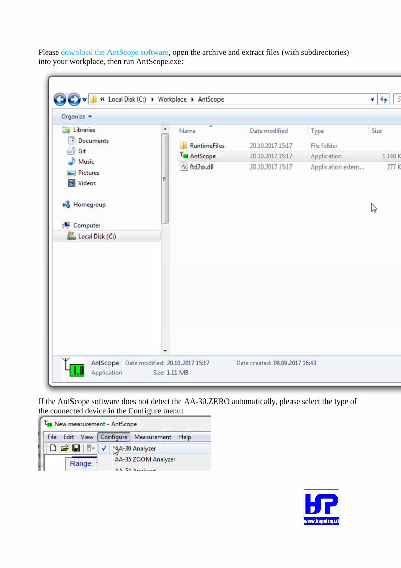
Please download the AntScope software, open the archive and extract files (with subdirectories) into your workplace, then run AntScope.exe:
If the AntScope software does not detect the AA-30.ZERO automatically, please select the type of the connected device in the Configure menu:
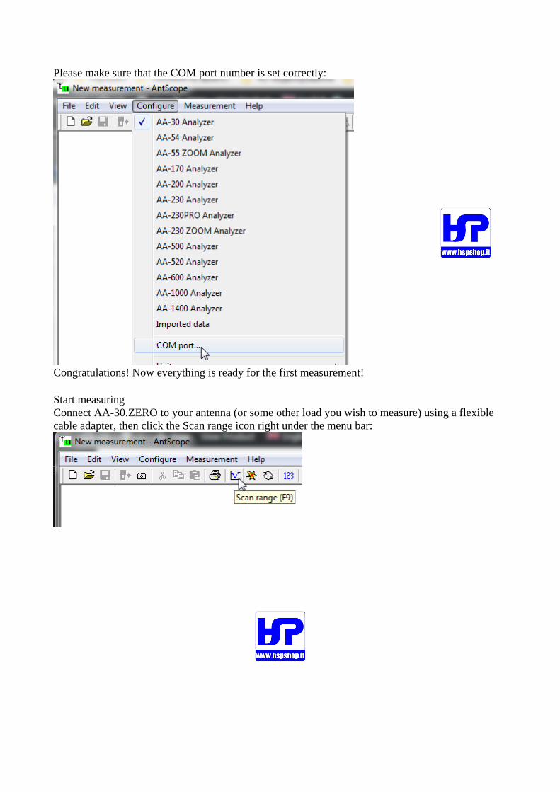
Please make sure that the COM port number is set correctly:
Congratulations! Now everything is ready for the first measurement!
Start measuring Connect AA-30.ZERO to your antenna (or some other load you wish to measure) using a flexible cable adapter, then click the Scan range icon right under the menu bar:

Click the Set full range button and click OK to start:
Notice the flashing LED at the PC board if the AA-30.ZERO…
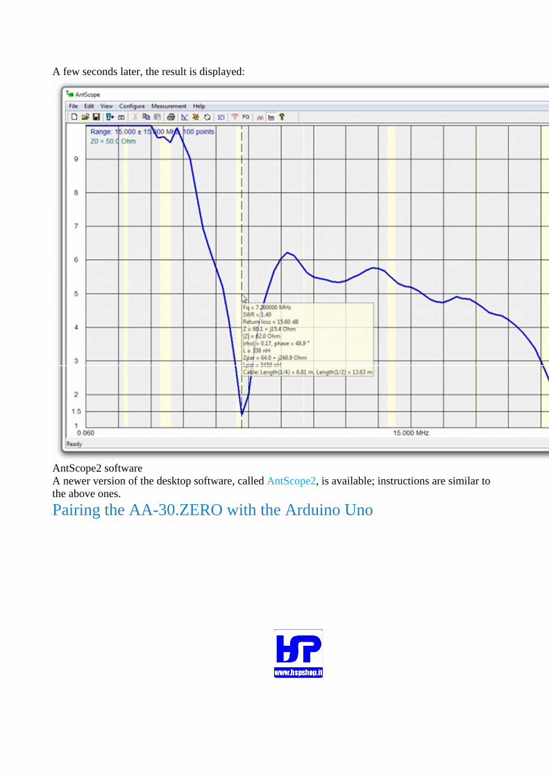
A few seconds later, the result is displayed:
AntScope2 software A newer version of the desktop software, called AntScope2, is available; instructions are similar to the above ones.
Pairing the AA-30.ZERO with the Arduino Uno

Installing headers The AA-30.ZERO is supplied with a straight breakaway headers kit:
If you want to connect your analyzer to an Arduino board, you should first solder the breakaway headers. After that, simply plug your AA-30.ZERO into your Arduino board:
Pins usage D0 – UART interface 1, TX, data out D1 – UART interface 1, RX, data in D4 – UART interface 2, TX, data out D7 – UART interface 2, RX, data in
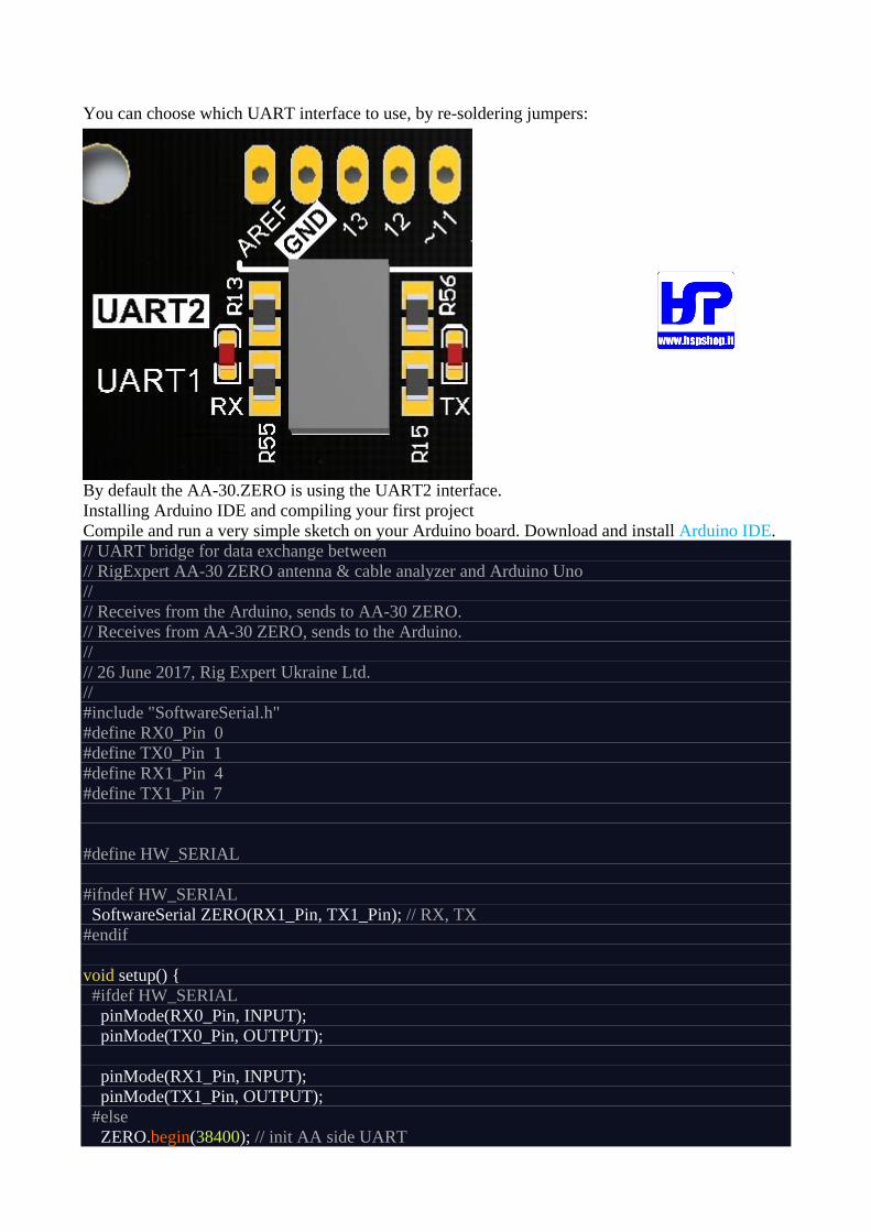
You can choose which UART interface to use, by re-soldering jumpers:
By default the AA-30.ZERO is using the UART2 interface. Installing Arduino IDE and compiling your first project Compile and run a very simple sketch on your Arduino board. Download and install Arduino IDE. // UART bridge for data exchange between // RigExpert AA-30 ZERO antenna & cable analyzer and Arduino Uno // // Receives from the Arduino, sends to AA-30 ZERO. // Receives from AA-30 ZERO, sends to the Arduino. // // 26 June 2017, Rig Expert Ukraine Ltd. // #include "SoftwareSerial.h" #define RX0_Pin 0 #define TX0_Pin 1 #define RX1_Pin 4 #define TX1_Pin 7
#define HW_SERIAL
#ifndef HW_SERIAL SoftwareSerial ZERO(RX1_Pin, TX1_Pin); // RX, TX #endif
void setup() { #ifdef HW_SERIAL pinMode(RX0_Pin, INPUT); pinMode(TX0_Pin, OUTPUT);
pinMode(RX1_Pin, INPUT); pinMode(TX1_Pin, OUTPUT); #else ZERO.begin(38400); // init AA side UART
ZERO.flush() Serial.begin(38400); // init PC side UART Serial.flush(); #endif }
void loop() { #ifdef HW_SERIAL //digitalWrite(TX0_Pin, digitalRead(RX1_Pin)); //digitalWrite(TX1_Pin, digitalRead(RX0_Pin)); if (PIND & (1 << 4)) PORTD |= (1 << 1); else PORTD &= ~(1 << 1); if (PIND & (1 << 0)) PORTD |= (1 << 7); else PORTD &= ~(1 << 7);
#else if (ZERO.available()) Serial.write(ZERO.read()); // data stream from AA to PC if (Serial.available()) ZERO.write(Serial.read()); // data stream from PC to AA #endif }
This simple “serial repeater” code provides two-way communication between your computer and the analyzer board. By the way, since the Arduino board now acts as a repeater, you can implement any code in it and moderate the exchange of data between your computer and the AA-30.ZERO.
Serial communication protocol Since the AA-30.ZERO was made for amateurs who are always wishing to construct something intersting, we had to take care of giving more freedom to the users of the analyzer.
Using the commands listed below, you can not only measure parameters of your antennas and cables, but also automate your analyzer, such as make it automatically perform periodic measurements immediately after the power is applied. This could be useful, for instance, in a case when the instrument is a part of a more complex system, for example, an antenna tuner.
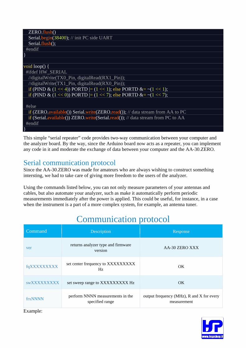
Communication protocol Command Description Response
ver returns analyzer type and firmware
version AA-30 ZERO XXX
fqXXXXXXXXX set center frequency to XXXXXXXXX
Hz OK
swXXXXXXXXX set sweep range to XXXXXXXXX Hz OK
frxNNNN perform NNNN measurements in the
specified range output frequency (MHz), R and X for every
measurement
Example:
FQ14500000\r\n SW1000000\r\n FRX10\r\n
14.000000,58.84,17.28\r\n 14.100000,69.74,16.79\r\n 14.200000,68.52,5.62\r\n 14.300000,62.49,2.79\r\n 14.400000,57.51,4.62\r\n 14.500000,55.38,9.11\r\n 14.600000,56.52,13.56\r\n 14.700000,59.40,17.41\r\n 14.800000,64.12,20.05\r\n 14.900000,71.13,22.01\r\n 15.000000,81.57,21.63\r\n
Data visualization
One of the simplest ways to visualize measurement results is to make your own application
Install Processing IDE First, download and install the Processing IDE. After the IDE software is installed, let’s compile this quite simple sketch: // 3D visualization for SWR measurements // For RigExpert AA-30 ZERO antenna & cable analyzer with Arduino Uno // // Receives data from AA-30 ZERO and makes a surface // which is a visualization of SWR as a function of time // // 26 June 2017, Rig Expert Ukraine Ltd. // import processing.serial.*;
Serial ZERO; int step; // Communication protocol steps (0 - set Freq; 1 - set Range; 2 - start measurements)
int maxSamples = 100; // Number of point to measure int maxSets = 50; // Time depth float points[][]; // Measurements data int sample; // current sample int set; // current data set int colors[]; // curve color int total; // total samples acquired boolean ready; // screen redrawn if True int Frequency; // current Frequensy int Range; // current Range
// Code to send command to Analyzer void serialize(String cmd) { int len = cmd.length(); int charPos = 0;
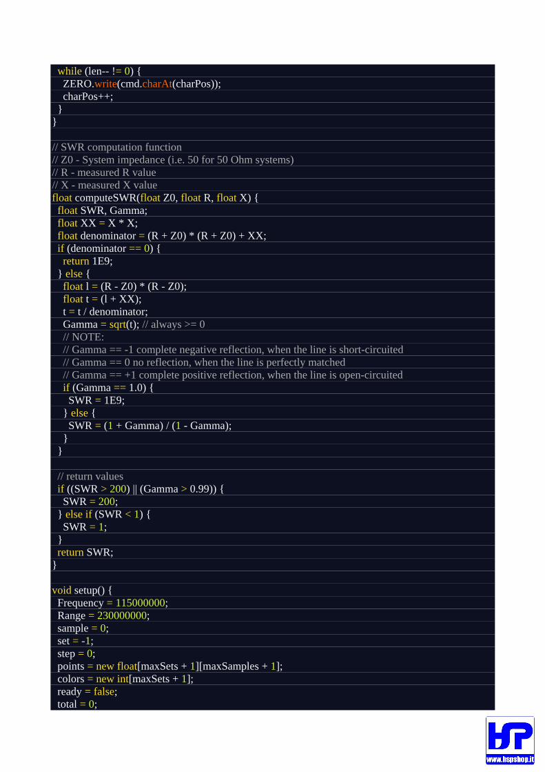
while (len-- != 0) { ZERO.write(cmd.charAt(charPos)); charPos++; } }
// SWR computation function // Z0 - System impedance (i.e. 50 for 50 Ohm systems) // R - measured R value // X - measured X value float computeSWR(float Z0, float R, float X) { float SWR, Gamma; float XX = X * X; float denominator = (R + Z0) * (R + Z0) + XX; if (denominator == 0) { return 1E9; } else { float l = (R - Z0) * (R - Z0); float t = (l + XX); t = t / denominator; Gamma = sqrt(t); // always >= 0 // NOTE: // Gamma == -1 complete negative reflection, when the line is short-circuited // Gamma == 0 no reflection, when the line is perfectly matched // Gamma == +1 complete positive reflection, when the line is open-circuited if (Gamma == 1.0) { SWR = 1E9; } else { SWR = (1 + Gamma) / (1 - Gamma); } }
// return values if ((SWR > 200) || (Gamma > 0.99)) { SWR = 200; } else if (SWR < 1) { SWR = 1; } return SWR; }
void setup() { Frequency = 115000000; Range = 230000000; sample = 0; set = -1; step = 0; points = new float[maxSets + 1][maxSamples + 1]; colors = new int[maxSets + 1]; ready = false; total = 0;

background(0); stroke(120, 240, 255, 255); strokeWeight(1); size(640, 480, P3D);
printArray(Serial.list()); // Replace COM name with one that matches your conditions ZERO = new Serial(this, "COM21", 38400); ZERO.bufferUntil(13); delay(1000); serialize("SW0\r\n"); }
void drawSurface() { ready = false; lights(); float sp = 0.001 * frameCount; camera((width / 3) * sin(sp), 0, 800, width / 2, height / 2, 0, 0, 1, 0);
background(0, 0, 0); textSize(30); fill(255, 255, 255); // ---------------- Axis --------------------- stroke(255, 255, 255, 128); line(0, height, 0, width, height, 0);
line(0, 0, 0, 0, height, 0); line(width, 0, 0, width, height, 0);
line(0, height, 5 * maxSets, 0, height, 0); line(width / 2, height, 5 * maxSets, width / 2, height, 0); line(width, height, 5 * maxSets, width, height, 0);
// ---------------- Freq. markers ---------------- stroke(255, 255, 255, 128); line(width / 2, 0, 0, width / 2, height, 0); textAlign(CENTER); text(Frequency / 1E3 + " kHz", width / 2, height, 5 * maxSets); text(((Frequency / 1E3) - (Range / 2E3)) + " kHz", 0, height, 5 * maxSets); text(((Frequency / 1E3) + (Range / 2E3)) + " kHz", width, height, 5 * maxSets);
// ----------------- Mode title ------------------ textAlign(LEFT); textSize(36); text("SWR as a function of time Graph", 0, -100, 0); textSize(30); if (mouseY < height / 5) { if (mouseX < width / 2) { fill(255, 0, 0); textAlign(RIGHT);
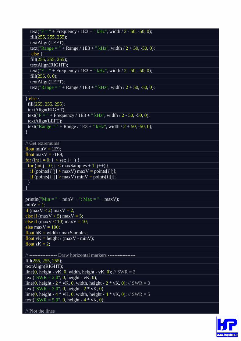
text("F = " + Frequency / 1E3 + " kHz", width / 2 - 50, -50, 0); fill(255, 255, 255); textAlign(LEFT); text("Range = " + Range / 1E3 + " kHz", width / 2 + 50, -50, 0); } else { fill(255, 255, 255); textAlign(RIGHT); text("F = " + Frequency / 1E3 + " kHz", width / 2 - 50, -50, 0); fill(255, 0, 0); textAlign(LEFT); text("Range = " + Range / 1E3 + " kHz", width / 2 + 50, -50, 0); } } else { fill(255, 255, 255); textAlign(RIGHT); text("F = " + Frequency / 1E3 + " kHz", width / 2 - 50, -50, 0); textAlign(LEFT); text("Range = " + Range / 1E3 + " kHz", width / 2 + 50, -50, 0); }
// Get extremums float minV = 1E9; float maxV = -1E9; for (int i = 0; i < set; i++) { for (int j = 0; j < maxSamples + 1; j++) { if (points[i][j] > maxV) maxV = points[i][j]; if (points[i][j] > maxV) minV = points[i][j]; } }
println("Min = " + minV + "; Max = " + maxV); minV = 1; if (maxV < 2) maxV = 2; else if (maxV < 5) maxV = 5; else if (maxV < 10) maxV = 10; else maxV = 100; float hK = width / maxSamples; float vK = height / (maxV - minV); float zK = 2;
// ----------------- Draw horizontal markers ----------------- fill(255, 255, 255); textAlign(RIGHT); line(0, height - vK, 0, width, height - vK, 0); // SWR = 2 text("SWR = 2.0", 0, height - vK, 0); line(0, height - 2 * vK, 0, width, height - 2 * vK, 0); // SWR = 3 text("SWR = 3.0", 0, height - 2 * vK, 0); line(0, height - 4 * vK, 0, width, height - 4 * vK, 0); // SWR = 5 text("SWR = 5.0", 0, height - 4 * vK, 0);
// Plot the lines
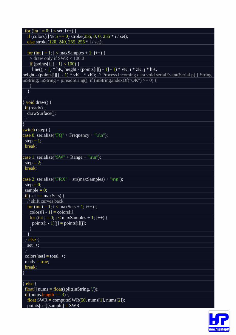
for (int i = 0; i < set; i++) { if (colors[i] % 5 == 0) stroke(255, 0, 0, 255 * i / set); else stroke(120, 240, 255, 255 * i / set);
for (int j = 1; j < maxSamples + 1; j++) { // draw only if SWR < 100.0 if (points[i][j - 1] < 100) { line((j - 1) * hK, height - (points[i][j - 1] - 1) * vK, i * zK, j * hK, height - (points[i][j] - 1) * vK, i * zK); // Process incoming data void serialEvent(Serial p) { String inString; inString = p.readString(); if (inString.indexOf("OK") >= 0) { } } } } void draw() { if (ready) { drawSurface(); } } switch (step) { case 0: serialize("FQ" + Frequency + "\r\n"); step = 1; break;
case 1: serialize("SW" + Range + "\r\n"); step = 2; break;
case 2: serialize("FRX" + str(maxSamples) + "\r\n"); step = 0; sample = 0; if (set == maxSets) { // shift curves back for (int i = 1; i < maxSets + 1; i++) { colors[i - 1] = colors[i]; for (int j = 0; j < maxSamples + 1; j++) { points[i - 1][j] = points[i][j]; } } } else { set++; } colors[set] = total++; ready = true; break; }
} else { float[] nums = float(split(inString, ',')); if (nums.length == 3) { float SWR = computeSWR(50, nums[1], nums[2]); points[set][sample] = SWR;
sample++; } } }
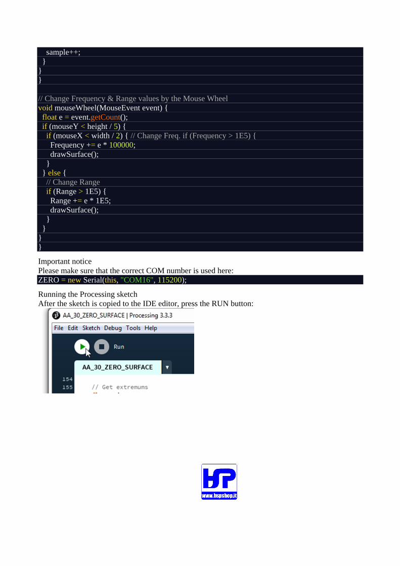
// Change Frequency & Range values by the Mouse Wheel void mouseWheel(MouseEvent event) { float e = event.getCount(); if (mouseY < height / 5) { if (mouseX < width / 2) { // Change Freq. if (Frequency > 1E5) { Frequency += e * 100000; drawSurface(); } } else { // Change Range if (Range > 1E5) { Range += e * 1E5; drawSurface(); } } } }
Important notice Please make sure that the correct COM number is used here: ZERO = new Serial(this, "COM16", 115200);
Running the Processing sketch After the sketch is copied to the IDE editor, press the RUN button:

A few seconds later, measurement results will be displayed on your screen, like this:
Let’s compare the resulting drawings with the chart that the AntScope program draws:
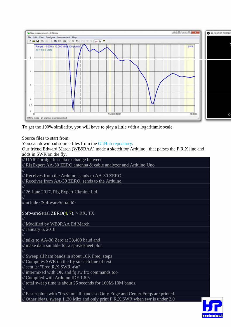
To get the 100% similarity, you will have to play a little with a logarithmic scale.
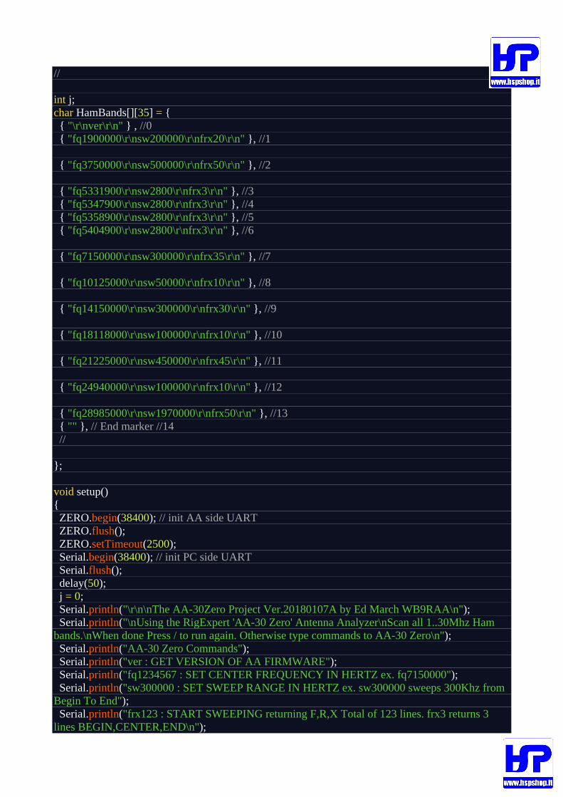
Source files to start from You can download source files from the GitHub repository. Our friend Edward March (WB9RAA) made a sketch for Arduino, that parses the F,R,X line and adds in SWR on the fly. // UART bridge for data exchange between // RigExpert AA-30 ZERO antenna & cable analyzer and Arduino Uno // // Receives from the Arduino, sends to AA-30 ZERO. // Receives from AA-30 ZERO, sends to the Arduino. // // 26 June 2017, Rig Expert Ukraine Ltd. // #include <SoftwareSerial.h>
SoftwareSerial ZERO(4, 7); // RX, TX // // Modified by WB9RAA Ed March // January 6, 2018 // // talks to AA-30 Zero at 38,400 baud and // make data suitable for a spreadsheet plot // // Sweep all ham bands in about 10K Freq. steps // Computes SWR on the fly so each line of text // sent is: "Freq,R,X,SWR \r\n" // intermixed with OK and fq sw frx commands too // Compiled with Arduino IDE 1.8.5 // total sweep time is about 25 seconds for 160M-10M bands. // // Faster plots with "frx3" on all bands so Only Edge and Center Freqs are printed. // Other ideas, sweep 1..30 Mhz and only print F,R,X,SWR when swr is under 2.0
//
int j; char HamBands[][35] = { { "\r\nver\r\n" } , //0 { "fq1900000\r\nsw200000\r\nfrx20\r\n" }, //1
{ "fq3750000\r\nsw500000\r\nfrx50\r\n" }, //2
{ "fq5331900\r\nsw2800\r\nfrx3\r\n" }, //3 { "fq5347900\r\nsw2800\r\nfrx3\r\n" }, //4 { "fq5358900\r\nsw2800\r\nfrx3\r\n" }, //5 { "fq5404900\r\nsw2800\r\nfrx3\r\n" }, //6
{ "fq7150000\r\nsw300000\r\nfrx35\r\n" }, //7
{ "fq10125000\r\nsw50000\r\nfrx10\r\n" }, //8
{ "fq14150000\r\nsw300000\r\nfrx30\r\n" }, //9
{ "fq18118000\r\nsw100000\r\nfrx10\r\n" }, //10
{ "fq21225000\r\nsw450000\r\nfrx45\r\n" }, //11
{ "fq24940000\r\nsw100000\r\nfrx10\r\n" }, //12
{ "fq28985000\r\nsw1970000\r\nfrx50\r\n" }, //13 { "" }, // End marker //14 //
};
void setup() { ZERO.begin(38400); // init AA side UART ZERO.flush(); ZERO.setTimeout(2500); Serial.begin(38400); // init PC side UART Serial.flush(); delay(50); j = 0; Serial.println("\r\n\nThe AA-30Zero Project Ver.20180107A by Ed March WB9RAA\n"); Serial.println("\nUsing the RigExpert 'AA-30 Zero' Antenna Analyzer\nScan all 1..30Mhz Ham bands.\nWhen done Press / to run again. Otherwise type commands to AA-30 Zero\n"); Serial.println("AA-30 Zero Commands"); Serial.println("ver : GET VERSION OF AA FIRMWARE"); Serial.println("fq1234567 : SET CENTER FREQUENCY IN HERTZ ex. fq7150000"); Serial.println("sw300000 : SET SWEEP RANGE IN HERTZ ex. sw300000 sweeps 300Khz from Begin To End"); Serial.println("frx123 : START SWEEPING returning F,R,X Total of 123 lines. frx3 returns 3 lines BEGIN,CENTER,END\n");

} long tmo = 250;
void loop() { if (ZERO.available()) { String s = ZERO.readStringUntil('\n');
s.replace("\r", ""); Serial.write(s.c_str()); // data stream from AA to PC
int i = s.indexOf(','); if (i > 0) { // Parse string into floats R & X i++; float R = s.substring(i).toFloat(); int ii = s.substring(i).indexOf(','); float X = s.substring(i + ii + 1).toFloat(); // // Compute SWR from R & X // float XX = X * X; float Rm = (R - 50) * (R - 50); float Rp = (R + 50) * (R + 50); float N = sqrt(Rm + XX); float D = sqrt(Rp + XX); float G = N / D; float vswr = (1 + G) / (1 - G); // Since we can not print floats we get int & fraction as INT's // if swr is 4.12 then v1=4 and v2=12 -- 1.04 then 1 and 4 printed as 1.04 using %d.%02d int v1 = vswr; int v2 = (vswr - v1) * 100; if (v1 < 0) { v1 = 99; v2 = 0; } char z[50]; sprintf(z, ",%d.%02d", v1, v2); // comput swr as string Serial.write(z); // append to string } Serial.write("\r\n"); // and terninate as it was with CR LF tmo = 250; } if (Serial.available()) { char c1 = Serial.read(); if (c1 == '/') { j = 0;
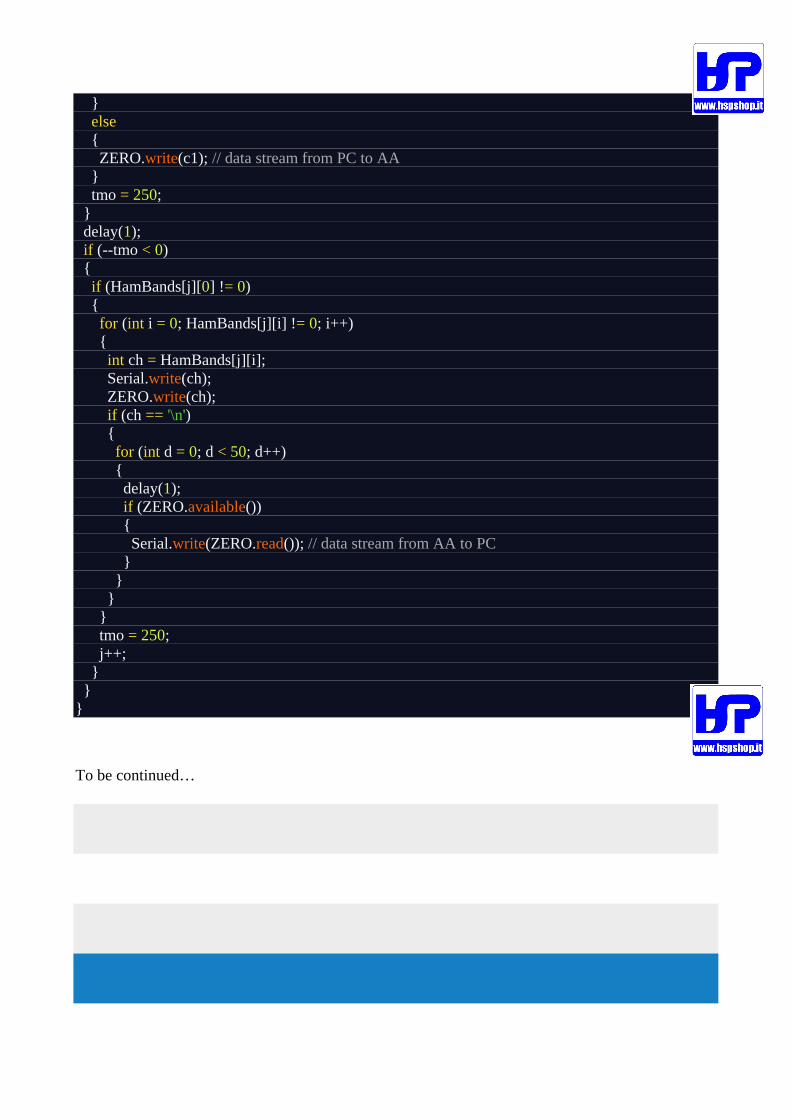
} else { ZERO.write(c1); // data stream from PC to AA } tmo = 250; } delay(1); if (--tmo < 0) { if (HamBands[j][0] != 0) { for (int i = 0; HamBands[j][i] != 0; i++) { int ch = HamBands[j][i]; Serial.write(ch); ZERO.write(ch); if (ch == '\n') { for (int d = 0; d < 50; d++) { delay(1); if (ZERO.available()) { Serial.write(ZERO.read()); // data stream from AA to PC } } } } tmo = 250; j++; } } }
To be continued…


![Skaffold - storage.googleapis.com · [getting-started getting-started] Hello world! [getting-started getting-started] Hello world! [getting-started getting-started] Hello world! 5.](https://static.fdocuments.us/doc/165x107/5ec939f2a76a033f091c5ac7/skaffold-getting-started-getting-started-hello-world-getting-started-getting-started.jpg)