Getting Started with MCUXpresso SDK - NXP … history ... MCUXpresso SDK devices folder is designed...
76
1 Overview The MCUXpresso Software Development Kit (SDK) provides comprehensive software support for Kinetis and LPC Microcontrollers. The MCUXpresso SDK includes a flexible set of peripheral drivers designed to speed up and simplify development of embedded applications. Along with the peripheral drivers, the MCUXpresso SDK provides an extensive and rich set of example applications covering everything from basic peripheral use case examples to full demo applications. The MCUXpresso SDK contains FreeRTOS, a USB host and device stack, and various other middleware to support rapid development. For supported toolchain versions, see the MCUXpresso SDK Release Notes (document MCUXSDKRN). For the latest version of this and other MCUXpresso SDK documents, see the MCUXpresso SDK homepage MCUXpresso-SDK: Software Development Kit for MCUXpresso. NXP Semiconductors Document Number: MCUXSDKGSUG User's Guide Rev. 3, 03/2017 Getting Started with MCUXpresso SDK Contents 1 Overview................................ ................................ 1 2 MCUXpresso SDK Board Support Folders.................................................. .................. 2 3 Run a demo application using IAR....... ..................4 4 Run a demo using Keil® MDK/ μVision.................................................................... 9 5 Run a demo using Kinetis Design Studio IDE.............................................. .............. 15 6 Run a demo using ARM® GCC.......... ................. 30 7 Run a demo using MCUXpresso IDE v10.0.0..................................................... ............. 38 8 MCUXpresso Config Tools Project Generator.............................................. ................ 63 9 Appendix A - How to determine COM port.........................................................................69 10 Appendix B - Default debug interfaces ................ 71 11 Appendix C - Updating debugger firmware................................................ ................ 73 12 Revision history.................................................... 75
Transcript of Getting Started with MCUXpresso SDK - NXP … history ... MCUXpresso SDK devices folder is designed...

1 OverviewThe MCUXpresso Software Development Kit (SDK) providescomprehensive software support for Kinetis and LPCMicrocontrollers. The MCUXpresso SDK includes a flexibleset of peripheral drivers designed to speed up and simplifydevelopment of embedded applications. Along with theperipheral drivers, the MCUXpresso SDK provides anextensive and rich set of example applications coveringeverything from basic peripheral use case examples to fulldemo applications. The MCUXpresso SDK containsFreeRTOS, a USB host and device stack, and various othermiddleware to support rapid development.
For supported toolchain versions, see the MCUXpresso SDKRelease Notes (document MCUXSDKRN).
For the latest version of this and other MCUXpresso SDKdocuments, see the MCUXpresso SDK homepageMCUXpresso-SDK: Software Development Kit forMCUXpresso.
NXP Semiconductors Document Number: MCUXSDKGSUG
User's Guide Rev. 3, 03/2017
Getting Started with MCUXpressoSDK
Contents
1 Overview................................ ................................ 1
2 MCUXpresso SDK Board SupportFolders.................................................. .................. 2
3 Run a demo application using IAR....... ..................4
4 Run a demo using Keil® MDK/μVision.................................................................... 9
5 Run a demo using Kinetis DesignStudio IDE.............................................. .............. 15
6 Run a demo using ARM® GCC.......... .................30
7 Run a demo using MCUXpresso IDEv10.0.0..................................................... ............. 38
8 MCUXpresso Config Tools ProjectGenerator.............................................. ................ 63
9 Appendix A - How to determine COMport.........................................................................69
10 Appendix B - Default debug interfaces ................ 71
11 Appendix C - Updating debuggerfirmware................................................ ................ 73
12 Revision history.................................................... 75

Application Code
Stacks and Middleware(Connectivity, Security,DMA, Filesystem, etc,)
Board Support
Peripheral DriversReal Time Kernel(FreeRTOS)
CMSIS-CORE and CMSIS-DSP(Device Header Files: Core Access Functions, Intrinsics, Peripheral & Interrupt Definitions, DSP Library)
Microcontroller Hardware
Figure 1. MCUXpresso SDK layers
2 MCUXpresso SDK Board Support FoldersMCUXpressoSDK board support provides example applications for NXP development and evaluation boards for ARM®
Cortex®-M cores, including Freedom, Tower System, and LPCXpresso boards. Board support packages are found inside ofthe top level boards folder, and each supported board has its own folder (an MCUXpresso SDK package can support multipleboards). Within each <board_name> folder there are various sub-folders to classify the type of examples they contain. Theseinclude (but are not limited to):
• cmsis_driver_examples: Simple applications intended to concisely illustrate how to use CMSIS drivers.• demo_apps: Full-featured applications intended to highlight key functionality and use cases of the target MCU. These
applications typically use multiple MCU peripherals and may leverage stacks and middleware.• driver_examples: Simple applications intended to concisely illustrate how to use the MCUXpresso SDK’s peripheral
drivers for a single use case. These applications typically only use a single peripheral, but there are cases wheremultiple are used (for example, ADC conversion using DMA).
• emwin_examples: Applications that use the emWin GUI widgets.• rtos_examples: Basic FreeRTOSTM OS examples showcasing the use of various RTOS objects (semaphores, queues,
and so on) and interfacing with the MCUXpresso SDK’s RTOS drivers• usb_examples: Applications that use the USB host/device/OTG stack.
2.1 Example Application Structure
This section describes how the various types of example applications interact with the other components in the MCUXpressoSDK. To get a comprehensive understanding of all MCUXpresso SDK components and folder structure, see theMCUXpresso SDK API Reference Manual document (MCUXSDKAPIRM).
Each <board_name> folder in the boards directory contains a comprehensive set of examples that are relevant to that specificpiece of hardware. We’ll discuss the hello_world example (part of the demo_apps folder), but the same general rules apply toany type of example in the <board_name> folder.
MCUXpresso SDK Board Support Folders
Getting Started with MCUXpresso SDK, Rev. 3, 03/2017
2 NXP Semiconductors

In the hello_world application folder you see this:
Figure 2. Application folder structure
All files in the application folder are specific to that example, so it’s very easy to copy-paste an existing example to startdeveloping a custom application based on a project provided in the MCUXpresso SDK.
2.2 Locating Example Application Source Files
When opening an example application in any of the supported IDEs, there are a variety of source files referenced. TheMCUXpresso SDK devices folder is designed to be the "golden core" of the application and is, therefore, the centralcomponent to all example applications. Because it’s a core component, all of the examples reference the same source filesand, if one of these files is modified, it could potentially impact the behavior of other examples.
The main areas of the MCUXpresso SDK tree used in all example applications are:
• devices/<device_name>: The device’s CMSIS header file, MCUXpresso SDK feature file and a few other things.• devices/<device_name>/cmsis_drivers: All the CMSIS drivers for your specific MCU.• devices/<device_name>/drivers: All of the peripheral drivers for your specific MCU.
MCUXpresso SDK Board Support Folders
Getting Started with MCUXpresso SDK, Rev. 3, 03/2017
NXP Semiconductors 3
• devices/<device_name>/<tool_name>: Toolchain-specific startup code. Vector table definitions are here.• devices/<device_name>/utilities: Items such as the debug console that are used by many of the example applications.
For examples containing middleware/stacks or a RTOS, there are references to the appropriate source code. Middlewaresource files are located in the middleware folder and RTOSes are in the rtos folder. Again, the core files of each of these areshared, so modifying them could have potential impacts on other projects that depend on them.
3 Run a demo application using IARThis section describes the steps required to build, run, and debug example applications provided in the MCUXpresso SDK.The hello_world demo application targeted for the FRDM-K64F Freedom hardware platform is used as an example, althoughthese steps can be applied to any example application in the MCUXpresso SDK.
3.1 Build an example application
The following steps guide you through opening the hello_world example application. These steps may change slightly forother example applications as some of these applications may have additional layers of folders in their path.
1. If not already done, open the desired demo application workspace. Most example application workspace files can belocated using the following path:
<install_dir>/boards/<board_name>/<example_type>/<application_name>/iar
Using the FRDM-K64F Freedom hardware platform as an example, the hello_world workspace is located in
<install_dir>/boards/frdmk64f/demo_apps/hello_world/iar/hello_world.eww
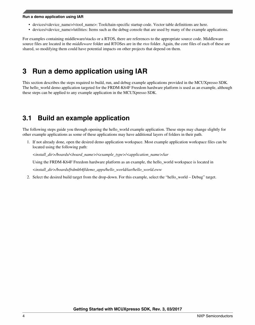
2. Select the desired build target from the drop-down. For this example, select the “hello_world – Debug” target.
Run a demo application using IAR
Getting Started with MCUXpresso SDK, Rev. 3, 03/2017
4 NXP Semiconductors
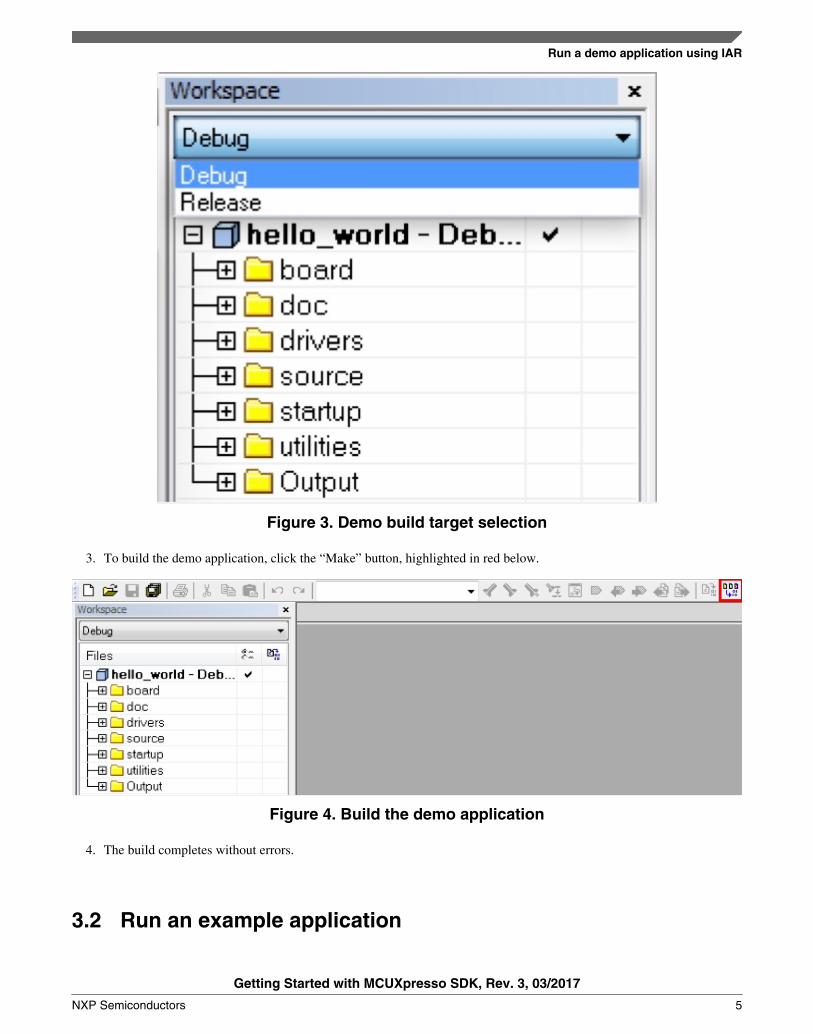
Figure 3. Demo build target selection
3. To build the demo application, click the “Make” button, highlighted in red below.
Figure 4. Build the demo application
4. The build completes without errors.
3.2 Run an example application
Run a demo application using IAR
Getting Started with MCUXpresso SDK, Rev. 3, 03/2017
NXP Semiconductors 5

To download and run the application, perform these steps:
1. Reference the table in Appendix B to determine the debug interface that comes loaded on your specific hardwareplatform.
• For boards with CMSIS-DAP/mbed/DAPLink interfaces, visit developer.mbed.org/handbook/Windows-serial-configuration and follow the instructions to install the Windows® operating system serial driver. If running onLinux OS, this step is not required.
• The user should install LPCScrypt or MCUXpresso IDE to ensure LPC board drivers are installed.• For boards with P&E Micro interfaces, visit www.pemicro.com/support/downloads_find.cfm and download the
P&E Micro Hardware Interface Drivers package.2. Connect the development platform to your PC via USB cable.3. Open the terminal application on the PC, such as PuTTY or TeraTerm, and connect to the debug COM port (to
determine the COM port number, see Appendix A). Configure the terminal with these settings:a. 115200 or 9600 baud rate, depending on your board (reference BOARD_DEBUG_UART_BAUDRATE variable
in board.h file)b. No parityc. 8 data bitsd. 1 stop bit
Figure 5. Terminal (PuTTY) configuration4. In IAR, click the "Download and Debug" button to download the application to the target.
Run a demo application using IAR
Getting Started with MCUXpresso SDK, Rev. 3, 03/2017
6 NXP Semiconductors

Figure 6. Download and Debug button5. The application is then downloaded to the target and automatically runs to the main() function.
Figure 7. Stop at main() when running debugging
6. Run the code by clicking the "Go" button to start the application.
Figure 8. Go button7. The hello_world application is now running and a banner is displayed on the terminal. If this is not true, check your
terminal settings and connections.
Figure 9. Text display of the hello_world demo
Run a demo application using IAR
Getting Started with MCUXpresso SDK, Rev. 3, 03/2017
NXP Semiconductors 7

3.3 Build a multicore example application
This section describes the particular steps that need to be done in order to build and run a dual-core application. The demoapplications workspace files are located in this folder:
<install_dir>/boards/<board_name>/multicore_examples/<application_name><core_type>/iar
Begin with a simple dual-core version of the Hello World application. The multicore Hello World IAR workspaces arelocated in this folder:
<install_dir>/boards/lpcxpresso54114/multicore_examples/hello_world/cm0plus/iar/hello_world_cm0plus.eww
<install_dir>/boards/lpcxpresso54114/multicore_examples/hello_world/cm4/iar/hello_world_cm4.eww
Build both applications separately by clicking the “Make” button. It is requested to build the application for the auxiliary core(cm0plus) first, because the primary core application project (cm4) needs to know the auxiliary core application binary whenrunning the linker. It is not possible to finish the primary core linker when the auxiliary core application binary is not ready.
3.4 Run a multicore example application
The primary core debugger handles flashing of both the primary and the auxiliary core applications into the SoC flashmemory. To download and run the multicore application, switch to the primary core application project and perform steps 1 –4 as described in Section 3.2, "Run an example application". These steps are common for both single core and dual-coreapplications in IAR.
After clicking the “Download and Debug" button, the auxiliary core project is opened in the separate EWARM instance. Boththe primary and auxiliary image are loaded into the device flash memory, and the primary core application is executed. Itstops at the default C language entry point in the main() function.
Run both cores by clicking the "Start all cores" button to start the multicore application.
Figure 10. Start all cores button
During the primary core code execution, the auxiliary core code is re-allocated from the flash memory to the RAM, and theauxiliary core is released from the reset. The hello_world multicore application is now running and a banner is displayed onthe terminal. If this is not true, check your terminal settings and connections.
Figure 11. Hello World from primary core message
An LED controlled by the auxiliary core starts flashing, indicating that the auxiliary core has been released from the reset andis running correctly. When both cores are running, use the "Stop all cores" and "Start all cores" control buttons to stop or runboth cores simultaneously.
Run a demo application using IAR
Getting Started with MCUXpresso SDK, Rev. 3, 03/2017
8 NXP Semiconductors

Figure 12. "Stop all cores" and "Start all cores" control buttons
4 Run a demo using Keil® MDK/μVisionThis section describes the steps required to build, run, and debug example applications provided in the MCUXpresso SDK.The hello_world demo application targeted for the FRDM-K64F Freedom hardware platform is used as an example, althoughthese steps can be applied to any demo or example application in the MCUXpresso SDK.
4.1 Install CMSIS device pack
After the MDK tools are installed, Cortex® Microcontroller Software Interface Standard (CMSIS) device packs must beinstalled to fully support the device from a debug perspective. These packs include things such as memory map information,register definitions and flash programming algorithms. Follow these steps to install the appropriate CMSIS pack.
1. Open the MDK IDE, which is called μVision. In the IDE, select the “Pack Installer” icon.
Figure 13. Launch the Pack installer2. After the installation finishes, close the Pack Installer window and return to the μVision IDE.
4.2 Build an example application
• If not already done, open the desired example application workspace in: <install_dir>/boards/<board_name>/<example_type>/<application_name>/mdk
The workspace file is named <demo_name>.uvmpw, so for this specific example, the actual path is:
<install_dir>/boards/frdmk64f/demo_apps/hello_world/mdk/hello_world.uvmpw• To build the demo project, select the "Rebuild" button, highlighted in red.
Figure 14. Build the demo• The build completes without errors.
Run a demo using Keil® MDK/μVision
Getting Started with MCUXpresso SDK, Rev. 3, 03/2017
NXP Semiconductors 9

4.3 Run an example application
To download and run the application, perform these steps:
1. Reference the table in Appendix B to determine the debug interface that comes loaded on your specific hardwareplatform.
• For boards with the CMSIS-DAP/mbed/DAPLink interface, visit mbed Windows serial configuration and followthe instructions to install the Windows operating system serial driver. If running on Linux OS, this step is notrequired.
• The user should install LPCScrypt or MCUXpresso IDE to ensure LPC board drivers are installed.• For boards with a P&E Micro interface, visit www.pemicro.com/support/downloads_find.cfm and download and
install the P&E Micro Hardware Interface Drivers package.• If using J-Link either a standalone debug pod or OpenSDA, install the J-Link software (drivers and utilities) from
www.segger.com/jlink-software.html.• For boards with the OSJTAG interface, install the driver from www.keil.com/download/docs/408.
2. Connect the development platform to your PC via USB cable between the OpenSDA USB connector (may be namedOSJTAG on some boards) and the PC USB connector.
3. Open the terminal application on the PC, such as PuTTY or TeraTerm, and connect to the debug serial port number (todetermine the COM port number, see Appendix A). Configure the terminal with these settings:
a. 115200 or 9600 baud rate, depending on your board (reference BOARD_DEBUG_UART_BAUDRATE variablein board.h file)
b. No parityc. 8 data bitsd. 1 stop bit
Run a demo using Keil® MDK/μVision
Getting Started with MCUXpresso SDK, Rev. 3, 03/2017
10 NXP Semiconductors

Figure 15. Terminal (PuTTY) configurations4. In μVision, after the application is properly built, click the "Download" button to download the application to the
target.
Figure 16. Download button5. After clicking the “Download” button, the application downloads to the target and should be running. To debug the
application, click the “Start/Stop Debug Session” button, highlighted in red.
Run a demo using Keil® MDK/μVision
Getting Started with MCUXpresso SDK, Rev. 3, 03/2017
NXP Semiconductors 11

Figure 17. Stop at main() when run debugging
6. Run the code by clicking the “Run” button to start the application.
Figure 18. Go button
The hello_world application is now running and a banner is displayed on the terminal. If this is not true, check yourterminal settings and connections.
Run a demo using Keil® MDK/μVision
Getting Started with MCUXpresso SDK, Rev. 3, 03/2017
12 NXP Semiconductors

Figure 19. Text display of the hello_world demo
4.4 Build a multicore example application
This section describes the particular steps that need to be done in order to build and run a dual-core application. The demoapplications workspace files are located in this folder:
<install_dir>/boards/<board_name>/multicore_examples/<application_name><core_type>/mdk
Begin with a simple dual-core version of the Hello World application. The multicore Hello World Keil MSDK/μVisionworkspaces are located in this folder:
<install_dir>/boards/lpcxpresso54114/multicore_examples/hello_world/cm0plus/mdk/hello_world_cm0plus.uvmpw
<install_dir>/boards/lpcxpresso54114/multicore_examples/hello_world/cm4/mdk/hello_world_cm4.uvmpw
Build both applications separately by clicking the “Rebuild” button. Build the application for the auxiliary core (cm0plus)first, because the primary core application project (cm4) needs to know the auxiliary core application binary when runningthe linker. It is not possible to finish the primary core linker when the auxiliary core application binary is not ready.
4.5 Run a multicore example application
The primary core debugger handles flashing of both the primary and the auxiliary core applications into the SoC flashmemory. To download and run the multicore application, switch to the primary core application project and perform steps 1 –5 as described in Section 4.3, "Run an example application". These steps are common for both single core and dual-coreapplications in μVision.
Both the primary and the auxiliary image is loaded into the device flash memory. After clicking the “Run" button, theprimary core application is executed. During the primary core code execution, the auxiliary core code is re-allocated from theflash memory to the RAM, and the auxiliary core is released from the reset. The hello_world multicore application is nowrunning and a banner is displayed on the terminal. If this is not true, check your terminal settings and connections.
Run a demo using Keil® MDK/μVision
Getting Started with MCUXpresso SDK, Rev. 3, 03/2017
NXP Semiconductors 13

Figure 20. Hello World from primary core message
An LED controlled by the auxiliary core starts flashing, indicating that the auxiliary core has been released from the reset andis running correctly.
Attach the running application of the auxiliary core by opening the auxiliary core project in the second μVision instance, andclicking the “Start/Stop Debug Session” button. After doing this, the second debug session is opened and the auxiliary coreapplication can be debugged.
Figure 21. Debugging the auxiliary core application
Run a demo using Keil® MDK/μVision
Getting Started with MCUXpresso SDK, Rev. 3, 03/2017
14 NXP Semiconductors

5 Run a demo using Kinetis Design Studio IDENOTE
Ensure that you selected the Kinetis Design Studio IDE toolchain when you generated theMCUXpresso SDK Package.
This section describes the steps required to configure Kinetis Design Studio (KDS) IDE to build, run, and debug exampleapplications. The hello_world demo application targeted for the FRDM-K64F Freedom hardware platform is used as anexample, though these steps can be applied to any example application in the MCUXpresso SDK.
5.1 Select the workspace location
The first time that KDS IDE launches, it prompts the user to select a workspace location. KDS IDE is built on top of Eclipse,which uses workspace to store information about its current configuration, and in some use cases, source files for the projectsin the workspace. The location of the workspace can be anywhere, but it is recommended that the workspace be outside ofthe MCUXpresso SDK tree.
5.2 Updating the KDS IDE components
The user must update the KDS IDE installation before using the MCUXpresso SDK with it. How the update is performeddepends on the KDS IDE version.
5.2.1 Update KDS IDE 3.0 and KDS IDE 3.1
NOTEIf you have previously installed New Project Wizard for MCUXpresso SDK to KDS IDE,update it using the instructions described in the subsequent section.
1. Select the menu Help -> Install New Software.
Run a demo using Kinetis Design Studio IDE
Getting Started with MCUXpresso SDK, Rev. 3, 03/2017
NXP Semiconductors 15

Figure 22. Install new software2. Select "Freescale KDS Update Site" as the site to work with.
Run a demo using Kinetis Design Studio IDE
Getting Started with MCUXpresso SDK, Rev. 3, 03/2017
16 NXP Semiconductors
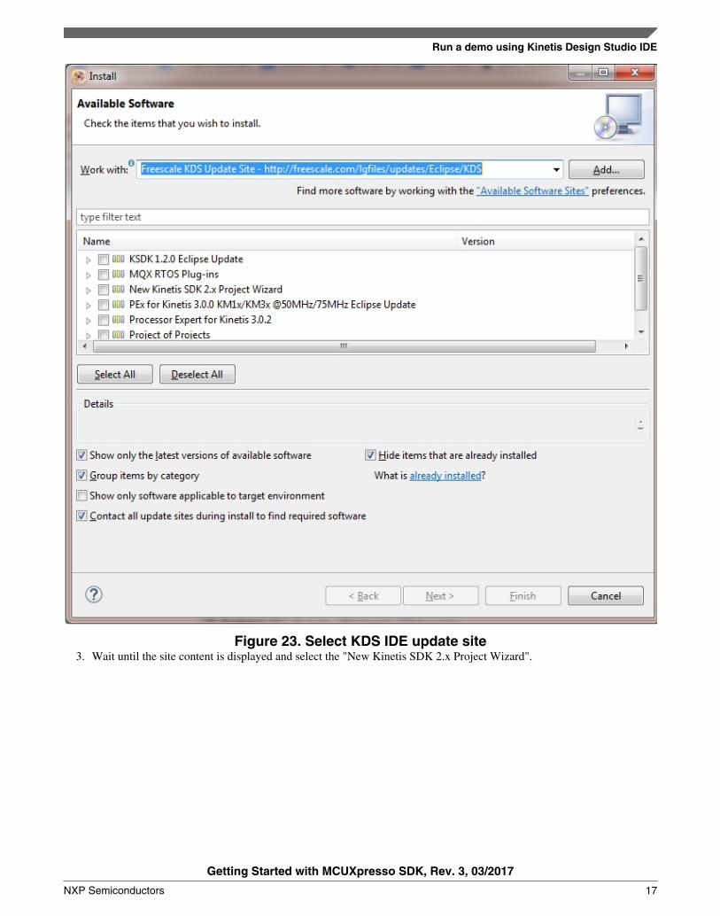
Figure 23. Select KDS IDE update site3. Wait until the site content is displayed and select the "New Kinetis SDK 2.x Project Wizard".
Run a demo using Kinetis Design Studio IDE
Getting Started with MCUXpresso SDK, Rev. 3, 03/2017
NXP Semiconductors 17

Figure 24. Select New Project Wizard4. Confirm and complete installation.5. Restart the IDE.
5.2.2 Update KDS IDE 3.2
1. Select the menu Help -> Check for Updates.
Run a demo using Kinetis Design Studio IDE
Getting Started with MCUXpresso SDK, Rev. 3, 03/2017
18 NXP Semiconductors

Figure 25. Check for updates2. Wait until the site content is displayed and select "New Kinetis SDK 2.x Project Wizard". Ensure that no other items
are selected.
Run a demo using Kinetis Design Studio IDE
Getting Started with MCUXpresso SDK, Rev. 3, 03/2017
NXP Semiconductors 19

Figure 26. Available updates for KDS IDE3. Confirm and complete update.4. Restart the IDE.
5.3 Build an example application
NOTEThe steps required for the Linux® OS and Mac® OS are identical to those for theWindows® operating system. The only difference is that the IDE looks slightly different.
1. Select "File -> Import" from the KDS IDE menu. In the window that appears, expand the "Project of Projects" folderand select "Existing Projects Sets". Then, click the "Next" button.
Run a demo using Kinetis Design Studio IDE
Getting Started with MCUXpresso SDK, Rev. 3, 03/2017
20 NXP Semiconductors

Figure 27. Selection of the correct import type in KDS IDE2. Click the "Browse" button next to the "Import from file:" option.
Run a demo using Kinetis Design Studio IDE
Getting Started with MCUXpresso SDK, Rev. 3, 03/2017
NXP Semiconductors 21

Figure 28. Projects directory selection window3. Point to the example application project, which can be found using this path:
<install_dir>/boards/<board_name>/<example_type>/<application_name>/kds
For this example, the specific location is:
<install_dir>/boards/frdmk64f/demo_apps/hello_world/kds
4. After pointing to the correct directory, your "Import Working Sets and Projects" window should look like the figurebelow. Click the "Finish" button.
Run a demo using Kinetis Design Studio IDE
Getting Started with MCUXpresso SDK, Rev. 3, 03/2017
22 NXP Semiconductors

Figure 29. Select K64F12 platform library project5. There are two project configurations (build targets) supported for each MCUXpresso SDK project:
• Debug – Compiler optimization is set to low, and debug information is generated for the executable. This targetshould be selected for development and debug.
• Release – Compiler optimization is set to high, and debug information is not generated. This target should beselected for final application deployment.
6. Choose the appropriate build target, "debug" or "release", by clicking the downward facing arrow next to the hammericon, as shown below. For this example, select the "debug" target.
Figure 30. Selection of the build target in KDS IDE
Run a demo using Kinetis Design Studio IDE
Getting Started with MCUXpresso SDK, Rev. 3, 03/2017
NXP Semiconductors 23

The project starts building after the build target is selected. To rebuild the library in the future, click the hammer icon(assuming the same build target is chosen).
5.4 Run an example application
NOTEThe steps required for the Linux OS and Mac OS are identical to those for the Windowsoperating system. The only difference is that the IDE looks slightly different. Anyplatform-specific steps are listed accordingly.
To download and run the application, perform these steps:
1. Reference the table in Appendix B to determine the debug interface that comes loaded on your specific hardwareplatform.
• For Windows operating system and Linux OS users, download the driver that corresponds to your debuginterface:
- For boards with the CMSIS-DAP/mbed/DAPLink interface, visit developer.mbed.org/handbook/Windows-serial-configuration and follow the instructions to install the Windows operating system serial driver. If runningon Linux OS, this step is not required.
- For boards with a P&E Micro interface, visit www.pemicro.com/support/downloads_find.cfm and downloadand install the P&E Micro Hardware Interface Drivers package.
• For Mac OS users, KDS only supports the J-Link OpenSDA interface.
Follow the instructions in Appendix C to update your board's OpenSDA interface to the J-Link OpenSDAapplication. Then, see www.segger.com/jlink-software.html to download the necessary software and drivers.
• For TWR-K80F150M and FRDM-K82F platforms, the J-Link OpenSDA application is required to be loadedbecause KDS IDE does not support CMSIS-DAP/mbed for those devices. See Appendix C for more information.
2. Connect the development platform to your PC via USB cable between the OpenSDA USB connector (may be namedOSJTAG for some boards) and the PC USB connector.
3. In the Windows operating system environment, open the terminal application on the PC, such as PuTTY or TeraTerm,and connect to the debug serial port number (to determine the COM port number, see Appendix A). For Linux OS,open your terminal application and connect to the appropriate device.
Configure the terminal with these settings:
a. 115200 or 9600 baud rate, depending on your board (reference BOARD_DEBUG_UART_BAUDRATE variablein board.h file)
b. No parityc. 8 data bitsd. 1 stop bit
Run a demo using Kinetis Design Studio IDE
Getting Started with MCUXpresso SDK, Rev. 3, 03/2017
24 NXP Semiconductors

Figure 31. Terminal (PuTTY) configurations4. For Linux OS users only, run the following commands in your terminal. These install libudev onto your system, which
is required by KDS IDE to launch the debugger.
user@ubuntu:~$ sudo apt-get install libudev-dev libudev1
user@ubuntu:~$ sudo ln –s /usr/lib/x86_64-linux-gnu/libudev.so /usr/lib/x86_64-linux-gnu/libudev.so.0
5. In KDS IDE, ensure that the debugger configuration is correct for the target you’re attempting to connect to.a. To check the available debugger configurations, click the small downward arrow next to the green “Debug”
button and select “Debug Configurations”.
Figure 32. Debug Configurations dialog button
Run a demo using Kinetis Design Studio IDE
Getting Started with MCUXpresso SDK, Rev. 3, 03/2017
NXP Semiconductors 25

b. In the Debug Configurations dialog box, select the debug configuration that corresponds to the hardware platformyou’re using. In this example, since the FRDM-K64F is used, select is the CMSIS-DAP/DAPLink option underOpenOCD. To determine the interface to use for other hardware platforms, refer to Appendix B.
After selecting the debugger interface, click the "Debug" button to launch the debugger.
Figure 33. Selection of the debug configuration and debugger launch
6. The application is downloaded to the target and automatically runs to main():
Run a demo using Kinetis Design Studio IDE
Getting Started with MCUXpresso SDK, Rev. 3, 03/2017
26 NXP Semiconductors

Figure 34. Stop at main() when running debugging
7. Start the application by clicking the "Resume" button:
Figure 35. Resume button
The hello_world application is now running and a banner is displayed on the terminal. If this is not true, check yourterminal settings and connections.
Figure 36. Text display of the hello_world demo
Run a demo using Kinetis Design Studio IDE
Getting Started with MCUXpresso SDK, Rev. 3, 03/2017
NXP Semiconductors 27

5.5 Create a new project
1. Select the menu File -> New -> MCUXpresso SDK SDK 2.x Project.
Figure 37. Select the menu File -> New -> MCUXpresso SDK 2.x Project2. Enter the project name and use the default project location.
Figure 38. Enter the project name3. The wizard supports three kinds of projects:
• Empty project for a board - see Board-><board>->New <board> project
Run a demo using Kinetis Design Studio IDE
Getting Started with MCUXpresso SDK, Rev. 3, 03/2017
28 NXP Semiconductors

• Example project - see Board -> <board> Examples -> <category> -> <example>
NOTEThis item allows a clone example project from boards/<board>/ folder in theKDS work space. It is available only if the MCUXpresso SDK packagecontains information about the project cloning.
• Empty project for a processor – see Processor -> <processor> -> New <processor> project
NOTEAn empty project means that there is no significant code in the main function.
Figure 39. Select board/processor4. For empty projects, you can select an RTOS and drivers:
• All drivers – to have all MCUXpresso SDK drivers and utilities copied into the project• Minimum set – to have only a basic set of drivers• Empty - to create a bare metal project
5. Finish.
You can now build and debug the project.
Run a demo using Kinetis Design Studio IDE
Getting Started with MCUXpresso SDK, Rev. 3, 03/2017
NXP Semiconductors 29

6 Run a demo using ARM® GCCThis section describes the steps to configure the command line ARM® GCC tools to build, run, and debug demo applicationsand necessary driver libraries provided in the MCUXpresso SDK. The hello_world demo application targeted for the FRDM-K64F Freedom hardware platform is used as an example, though these steps can be applied to any board, demo or exampleapplication in the MCUXpresso SDK.
6.1 Set up toolchain
This section contains the steps to install the necessary components required to build and run an MCUXpresso SDK demoapplication with the ARM GCC toolchain, as supported by the MCUXpresso SDK. There are many ways to use ARM GCCtools, but this example focuses on a Windows operating system environment. Though not discussed here, ARM GCC toolscan also be used with both Linux OS and Mac OSX.
6.1.1 Install GCC ARM Embedded tool chain
Download and run the installer from launchpad.net/gcc-arm-embedded. This is the actual toolset (in other words, compiler,linker, etc.). The GCC toolchain should correspond to the latest supported version, as described in the MCUXpresso SDKRelease Notes. (document MCUXSDKRN).
6.1.2 Install MinGW
The Minimalist GNU for Windows (MinGW) development tools provide a set of tools that are not dependent on third partyC-Runtime DLLs (such as Cygwin). The build environment used by the MCUXpresso SDK does not utilize the MinGWbuild tools, but does leverage the base install of both MinGW and MSYS. MSYS provides a basic shell with a Unix-likeinterface and tools.
1. Download the latest MinGW mingw-get-setup installer from sourceforge.net/projects/mingw/files/Installer/.2. Run the installer. The recommended installation path is C:\MinGW, however, you may install to any location.
NOTEThe installation path cannot contain any spaces.
3. Ensure that the “mingw32-base” and “msys-base” are selected under Basic Setup.
Figure 40. Setup MinGW and MSYS4. Click “Apply Changes” in the “Installation” menu and follow the remaining instructions to complete the installation.
Run a demo using ARM® GCC
Getting Started with MCUXpresso SDK, Rev. 3, 03/2017
30 NXP Semiconductors

Figure 41. Complete MinGW and MSYS installation5. Add the appropriate item to the Windows operating system path environment variable. It can be found under Control
Panel -> System and Security -> System -> Advanced System Settings in the "Environment Variables..." section. Thepath is:
<mingw_install_dir>\bin
Assuming the default installation path, C:\MinGW, an example is shown below. If the path is not set correctly, thetoolchain does not work.
NOTEIf you have "C:\MinGW\msys\x.x\bin" in your PATH variable (as required byKSDK 1.0.0), remove it to ensure that the new GCC build system works correctly.
Run a demo using ARM® GCC
Getting Started with MCUXpresso SDK, Rev. 3, 03/2017
NXP Semiconductors 31

Figure 42. Add Path to systems environment
6.1.3 Add a new system environment variable for ARMGCC_DIR
Create a new system environment variable and name it ARMGCC_DIR. The value of this variable should point to the ARMGCC Embedded tool chain installation path, which, for this example, is:
C:\Program Files (x86)\GNU Tools ARM Embedded\5.2 2015q4
Reference the installation folder of the GNU ARM GCC Embedded tools for the exact path name of your installation.
Run a demo using ARM® GCC
Getting Started with MCUXpresso SDK, Rev. 3, 03/2017
32 NXP Semiconductors

Figure 43. Add ARMGCC_DIR system variable
6.1.4 Install CMake
1. Download CMake 3.0.x from www.cmake.org/cmake/resources/software.html.2. Install CMake, ensuring that the option "Add CMake to system PATH" is selected when installing. The user chooses to
select whether it is installed into the PATH for all users or just the current user. In this example, it is installed for allusers.
Run a demo using ARM® GCC
Getting Started with MCUXpresso SDK, Rev. 3, 03/2017
NXP Semiconductors 33

Figure 44. Install CMake3. Follow the remaining instructions of the installer.4. You may need to reboot your system for the PATH changes to take effect.
6.2 Build an example application
To build an example application, follow these steps.
1. Open a GCC ARM Embedded tool chain command window. To launch the window, from the Windows operatingsystem Start menu, go to “Programs -> GNU Tools ARM Embedded <version>” and select “GCC Command Prompt”.
Figure 45. Launch command prompt2. Change the directory to the example application project directory, which has a path like this:
Run a demo using ARM® GCC
Getting Started with MCUXpresso SDK, Rev. 3, 03/2017
34 NXP Semiconductors

<install_dir>/boards/<board_name>/<example_type>/<application_name>/armgcc
For this example, the exact path is: <install_dir>/examples/frdmk64f/demo_apps/hello_world/armgcc
NOTETo change directories, use the 'cd' command.
3. Type “build_debug.bat” on the command line or double click on the "build_debug.bat" file in Windows Explorer toperform the build. The output is shown in this figure:
Figure 46. hello_world demo build successful
6.3 Run an example application
This section describes steps to run a demo application using J-Link GDB Server application. To perform this exercise, twothings must be done:
• Make sure that either:• The OpenSDA interface on your board is programmed with the J-Link OpenSDA firmware. To determine if your
board supports OpenSDA, see Appendix B. For instructions on reprogramming the OpenSDA interface, seeAppendix C. If your board does not support OpenSDA, then a standalone J-Link pod is required.
• You have a standalone J-Link pod that is connected to the debug interface of your board. Note that somehardware platforms require hardware modification in order to function correctly with an external debug interface.
After the J-Link interface is configured and connected, follow these steps to download and run the demo application:
1. Connect the development platform to your PC via USB cable between the OpenSDA USB connector (may be namedOSJTAG for some boards) and the PC USB connector. If using a standalone J-Link debug pod, also connect it to theSWD/JTAG connector of the board.
2. Open the terminal application on the PC, such as PuTTY or TeraTerm, and connect to the debug serial port number (todetermine the COM port number, see Appendix A). Configure the terminal with these settings:
a. 115200 or 9600 baud rate, depending on your board (reference BOARD_DEBUG_UART_BAUDRATE variablein board.h file)
b. No parityc. 8 data bitsd. 1 stop bit
Run a demo using ARM® GCC
Getting Started with MCUXpresso SDK, Rev. 3, 03/2017
NXP Semiconductors 35

Figure 47. Terminal (PuTTY) configurations3. Open the J-Link GDB Server application. Assuming the J-Link software is installed, the application can be launched by
going to the Windows operating system Start menu and selecting “Programs -> SEGGER -> J-Link <version> J-LinkGDB Server”.
4. Modify the settings as shown below. The target device selection chosen for this example is the MK64FN1M0xxx12.5. After it is connected, the screen should resemble this figure:
Run a demo using ARM® GCC
Getting Started with MCUXpresso SDK, Rev. 3, 03/2017
36 NXP Semiconductors
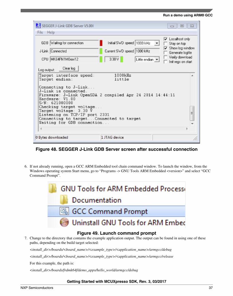
Figure 48. SEGGER J-Link GDB Server screen after successful connection
6. If not already running, open a GCC ARM Embedded tool chain command window. To launch the window, from theWindows operating system Start menu, go to “Programs -> GNU Tools ARM Embedded <version>” and select “GCCCommand Prompt”.
Figure 49. Launch command prompt7. Change to the directory that contains the example application output. The output can be found in using one of these
paths, depending on the build target selected:
<install_dir>/boards/<board_name>/<example_type>/<application_name>/armgcc/debug
<install_dir>/boards/<board_name>/<example_type>/<application_name>/armgcc/release
For this example, the path is:
<install_dir>/boards/frdmk64f/demo_apps/hello_world/armgcc/debug
Run a demo using ARM® GCC
Getting Started with MCUXpresso SDK, Rev. 3, 03/2017
NXP Semiconductors 37

8. Run the command “arm-none-eabi-gdb.exe <application_name>.elf”. For this example, it is “arm-none-eabi-gdb.exehello_world.elf”.
Figure 50. Run arm-none-eabi-gdb
9. Run these commands:a. "target remote localhost:2331"b. "monitor reset"c. "monitor halt"d. "load"e. "monitor reset"
10. The application is now downloaded and halted at the reset vector. Execute the “monitor go” command to start the demoapplication.
The hello_world application is now running and a banner is displayed on the terminal. If this is not true, check yourterminal settings and connections.
Figure 51. Text display of the hello_world demo
7 Run a demo using MCUXpresso IDE v10.0.0NOTE
Ensure that the MCUXpresso IDE toolchain is included when generating theMCUXpresso SDK Package.
Run a demo using MCUXpresso IDE v10.0.0
Getting Started with MCUXpresso SDK, Rev. 3, 03/2017
38 NXP Semiconductors

This section describes the steps required to configure MCUXpresso IDE v10.0.0 to build, run, and debug exampleapplications. The hello_world demo application targeted for the FRDM-K64F Freedom hardware platform is used as anexample, though these steps can be applied to any example application in the MCUXpresso SDK.
7.1 Select the workspace locationThe first time MCUXpresso IDE v10.0.0 launches, it prompts the user to select a workspace location. MCUXpresso IDEv10.0.0 is built on top of Eclipse, which uses workspace to store information about its current configuration, and in some usecases, source files for the projects in the workspace. The location of the workspace can be anywhere, but it is recommendedthat the workspace be outside of the MCUXpresso SDK tree.
7.2 Build an example application
To build an example application, follow these steps.
1. Drag and drop the SDK zip file into the “Installed SDKs” view to install an SDK. In the window that appears, click the“OK” button and wait until the import has finished.
Figure 52. Install an SDK2. On the Quickstart Panel, click “Import SDK example(s)…”.
Run a demo using MCUXpresso IDE v10.0.0
Getting Started with MCUXpresso SDK, Rev. 3, 03/2017
NXP Semiconductors 39
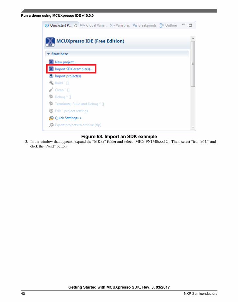
Figure 53. Import an SDK example3. In the window that appears, expand the “MKxx” folder and select “MK64FN1M0xxx12”. Then, select “frdmk64f” and
click the “Next” button.
Run a demo using MCUXpresso IDE v10.0.0
Getting Started with MCUXpresso SDK, Rev. 3, 03/2017
40 NXP Semiconductors
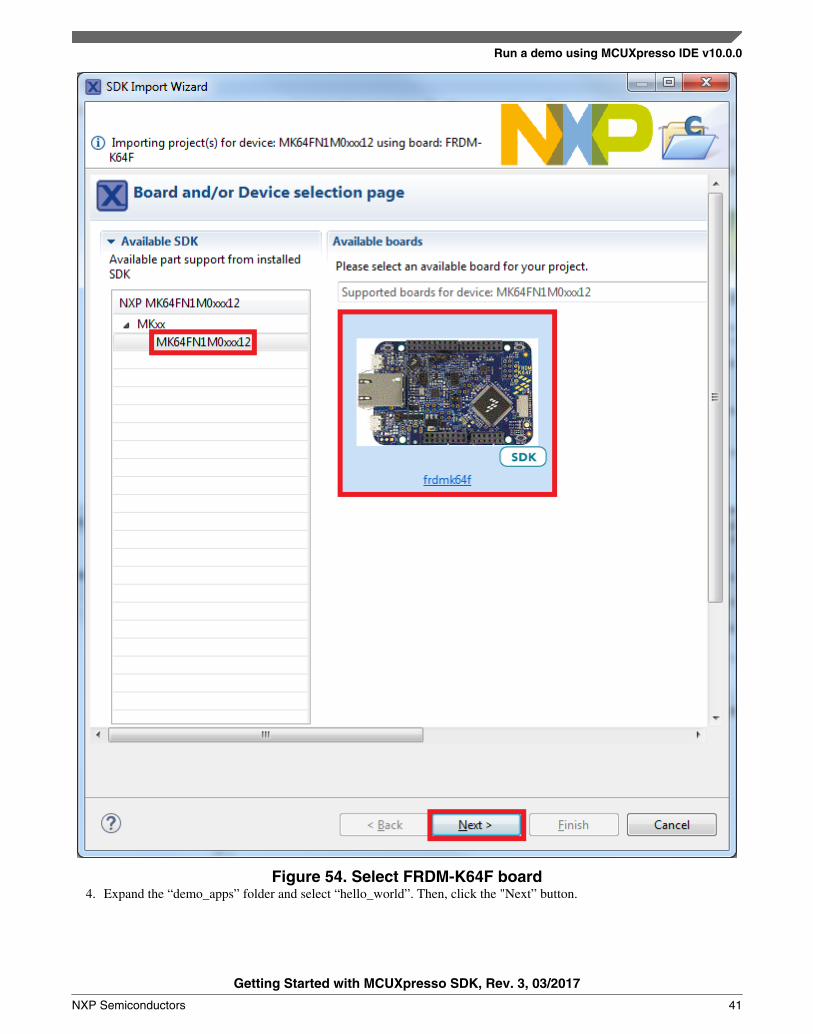
Figure 54. Select FRDM-K64F board4. Expand the “demo_apps” folder and select “hello_world”. Then, click the "Next” button.
Run a demo using MCUXpresso IDE v10.0.0
Getting Started with MCUXpresso SDK, Rev. 3, 03/2017
NXP Semiconductors 41

Figure 55. Select "hello_world"5. Ensure the option “Redlib: Use floating point version of printf” is selected if the cases print floating point numbers on
the terminal (for demo applications such as dac32_adc12, dac_adc, dac_cadc, ecompass, sai, coremark,mbedtls_benchmark, wolfssl_benchmark, and for mmcau_examples such as mmcau_api). Otherwise, there is no needto select it. Click the “Finish” button.
Run a demo using MCUXpresso IDE v10.0.0
Getting Started with MCUXpresso SDK, Rev. 3, 03/2017
42 NXP Semiconductors

Figure 56. Select "User floating print version of printf"
7.3 Run an example application
For more information on debug probe support in the MCUXpresso IDE v10.0.0, visit community.nxp.com.
To download and run the application, perform these steps:
1. Reference the table in Appendix B to determine the debug interface that comes loaded on your specific hardwareplatform. For LPCXpresso boards, install the DFU jumper for the debug probe, then connect the debug probe USBconnector.
Run a demo using MCUXpresso IDE v10.0.0
Getting Started with MCUXpresso SDK, Rev. 3, 03/2017
NXP Semiconductors 43

• For boards with a P&E Micro interface, visit www.pemicro.com/support/downloads_find.cfm and download andinstall the P&E Micro Hardware Interface Drivers package.
• For the MRB-KW01 board, visit www.nxp.com/USB2SER to download the serial driver. This board does notsupport the OpenSDA. Therefore, an external debug probe (such as a J-Link) is required. The steps belowreferencing the OpenSDA do not apply because there is only a single USB connector for the serial output.
• If using J-Link with either a standalone debug pod or OpenSDA, install the J-Link software (drivers and utilities)from www.segger.com/jlink-software.html.
• For boards with the OSJTAG interface, install the driver from www.keil.com/download/docs/408.2. Connect the development platform to your PC via USB cable.3. Open the terminal application on the PC, such as PuTTY or TeraTerm, and connect to the debug serial port number (to
determine the COM port number, see Appendix A). Configure the terminal with these settings:a. 115200 or 9600 baud rate, depending on your board (reference BOARD_DEBUG_UART_BAUDRATE variable
in board.h file)b. No parityc. 8 data bitsd. 1 stop bit
Run a demo using MCUXpresso IDE v10.0.0
Getting Started with MCUXpresso SDK, Rev. 3, 03/2017
44 NXP Semiconductors
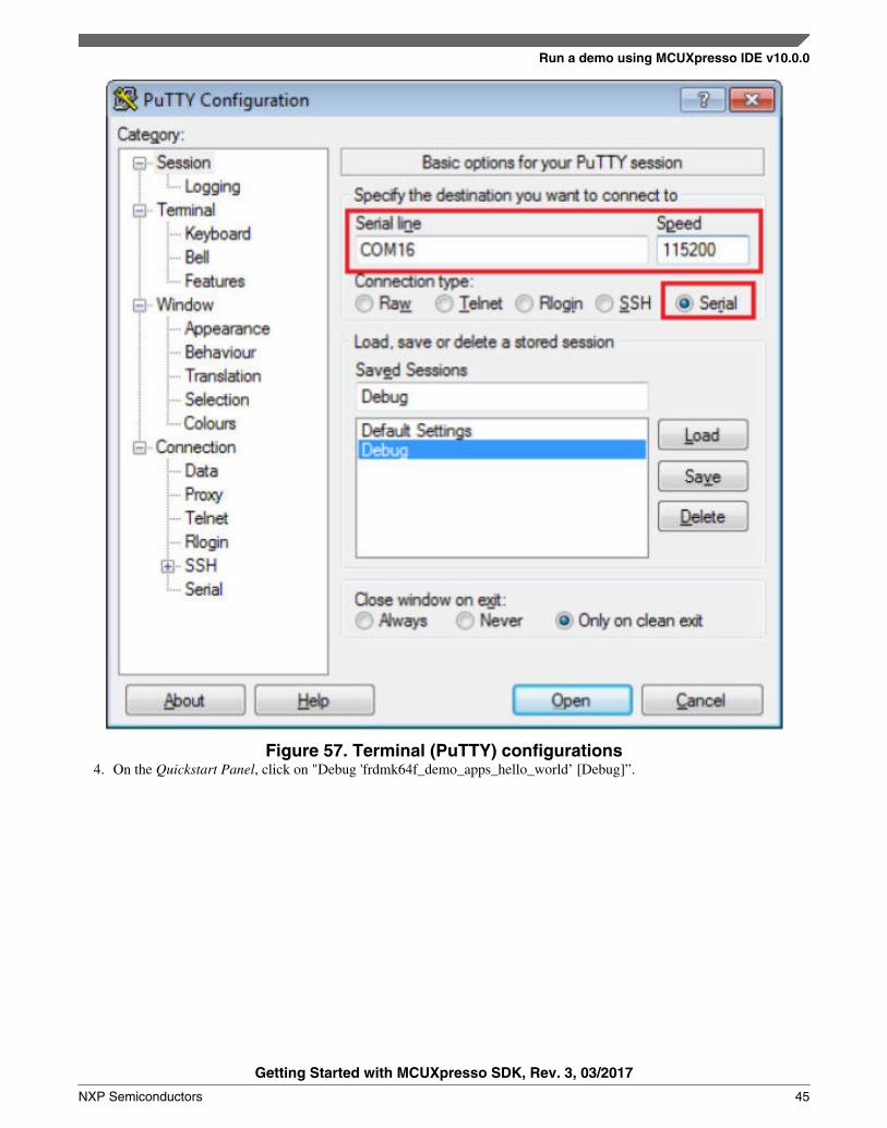
Figure 57. Terminal (PuTTY) configurations4. On the Quickstart Panel, click on "Debug 'frdmk64f_demo_apps_hello_world’ [Debug]”.
Run a demo using MCUXpresso IDE v10.0.0
Getting Started with MCUXpresso SDK, Rev. 3, 03/2017
NXP Semiconductors 45

Figure 58. Debug "hello_world" case5. The first time you debug a project, the Debug Emulator Selection Dialog is displayed, showing all supported probes
that are attached to your computer. Select the probe through which you want to debug and click the “OK” button. (Forany future debug sessions, the stored probe selection is automatically used, unless the probe cannot be found.)
Run a demo using MCUXpresso IDE v10.0.0
Getting Started with MCUXpresso SDK, Rev. 3, 03/2017
46 NXP Semiconductors

Figure 59. Attached Probes: debug emulator selection6. The application is downloaded to the target and automatically runs to main():
Run a demo using MCUXpresso IDE v10.0.0
Getting Started with MCUXpresso SDK, Rev. 3, 03/2017
NXP Semiconductors 47

Figure 60. Stop at main() when running debugging7. Start the application by clicking the "Resume" button.
Figure 61. Resume button
Run a demo using MCUXpresso IDE v10.0.0
Getting Started with MCUXpresso SDK, Rev. 3, 03/2017
48 NXP Semiconductors

The hello_world application is now running and a banner is displayed on the terminal. If this is not the case, check yourterminal settings and connections.
Figure 62. Text display of the hello_world demo
7.4 Build a multicore example application
This section describes the steps required to configure MCUXpresso IDE v10.0.0 to build, run, and debug multicore exampleapplications. The dual-core version of hello_world example application targeted for the LPCXpresso54114 hardwareplatform is used as an example, though these steps can be applied to any multicore example application in the MCUXpressoSDK
1. Multicore examples are imported into the workspace in a similar way as single core applications. When the SDK zippackage for LPCXpresso54114 is installed and available in the “Installed SDKs” view, click “Import SDK example(s)…” on the Quickstart Panel. In the window that appears, expand the “LPCxx” folder and select “LPC54114J256”.Then, select “lpcxpresso54114” and click the “Next” button.
Run a demo using MCUXpresso IDE v10.0.0
Getting Started with MCUXpresso SDK, Rev. 3, 03/2017
NXP Semiconductors 49
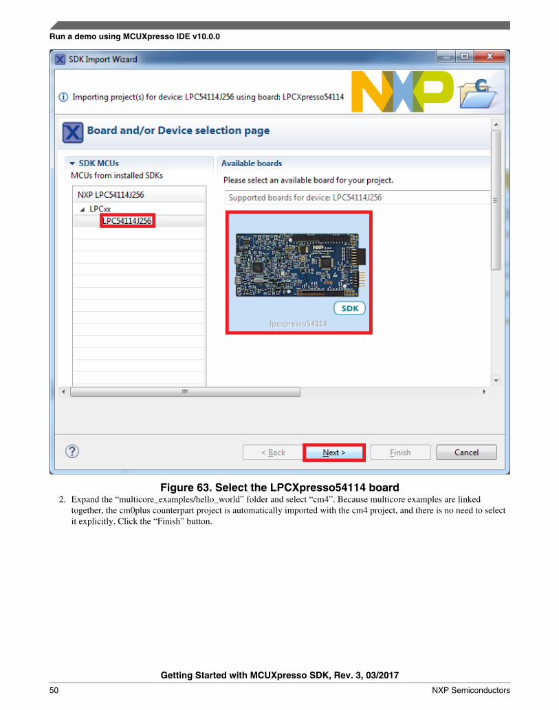
Figure 63. Select the LPCXpresso54114 board2. Expand the “multicore_examples/hello_world” folder and select “cm4”. Because multicore examples are linked
together, the cm0plus counterpart project is automatically imported with the cm4 project, and there is no need to selectit explicitly. Click the “Finish” button.
Run a demo using MCUXpresso IDE v10.0.0
Getting Started with MCUXpresso SDK, Rev. 3, 03/2017
50 NXP Semiconductors

Figure 64. Select the hello_world multicore example3. Now, two projects should be imported into the workspace. To start building the multicore application, highlight the
lpcxpresso54114_multicore_examples_hello_world_cm4 project (multicore master project) in the Project Explorer,then choose the appropriate build target, "Debug" or "Release", by clicking the downward facing arrow next to thehammer icon, as shown below. For this example, select the "Debug" target.
Run a demo using MCUXpresso IDE v10.0.0
Getting Started with MCUXpresso SDK, Rev. 3, 03/2017
NXP Semiconductors 51

Figure 65. Selection of the build target in MCUXpresso IDE
The project starts building after the build target is selected. Because of the project reference settings in multicore projects,triggering the build of the primary core application (cm4) causes the referenced auxiliary core application (cm0plus) to buildas well.
NOTEWhen the 'Release' build is requested, it is necessary to change the build configuration ofboth the primary and auxiliary core application projects first. To do this, select bothprojects in the Project Explorer view by clicking to select the first project, then usingshift-click or control-click to select the second project. Right click in the Project Explorerview to display the context-sensitive menu and select 'Build Configurations->Set Active->Release'. This also possible to do using the menu item 'Project->Build Configuration->Set Active->Release'. After switching to the 'Release' build configuration, the build ofthe multicore example can be started by triggering the primary core application (cm4)build.
Run a demo using MCUXpresso IDE v10.0.0
Getting Started with MCUXpresso SDK, Rev. 3, 03/2017
52 NXP Semiconductors

Figure 66. Switching multicore projects into the Release build configuration
7.5 Run a multicore example application
The primary core debugger handles flashing of both the primary and the auxiliary core applications into the SoC flashmemory. To download and run the multicore application, switch to the primary core application project and perform all stepsas described in Section 7.3, "Run an example application". These steps are common for both single core applications and theprimary side of dual-core applications, ensuring both sides of the multicore application are properly loaded and started.However, there is one additional dialogue that is specific to multicore examples, and requires selecting the target core. Seethe following figures as reference.
Run a demo using MCUXpresso IDE v10.0.0
Getting Started with MCUXpresso SDK, Rev. 3, 03/2017
NXP Semiconductors 53
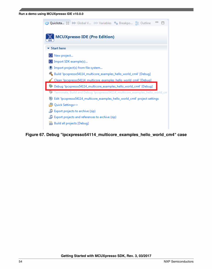
Figure 67. Debug "lpcxpresso54114_multicore_examples_hello_world_cm4" case
Run a demo using MCUXpresso IDE v10.0.0
Getting Started with MCUXpresso SDK, Rev. 3, 03/2017
54 NXP Semiconductors
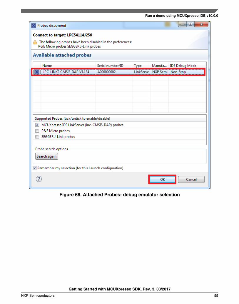
Figure 68. Attached Probes: debug emulator selection
Run a demo using MCUXpresso IDE v10.0.0
Getting Started with MCUXpresso SDK, Rev. 3, 03/2017
NXP Semiconductors 55

Figure 69. Target core selection dialog
Run a demo using MCUXpresso IDE v10.0.0
Getting Started with MCUXpresso SDK, Rev. 3, 03/2017
56 NXP Semiconductors

Figure 70. Stop the primary core application at main() when running debugging
After clicking the "Resume All Debug sessions" button, the hello_world multicore application runs and a banner is displayedon the terminal. If this is not the case, check your terminal settings and connections.
Run a demo using MCUXpresso IDE v10.0.0
Getting Started with MCUXpresso SDK, Rev. 3, 03/2017
NXP Semiconductors 57

Figure 71. Hello World from the primary core message
An LED controlled by the auxiliary core starts flashing, indicating that the auxiliary core has been released from the reset andrunning correctly. It is also possible to debug both sides of the multicore application in parallel. After creating the debugsession for the primary core, perform same steps also for the auxiliary core application. Highlight thelpcxpresso54114_multicore_examples_hello_world_cm0plus project (multicore slave project) in the Project Explorer. On theQuickstart Panel, click “Debug ‘lpcxpresso54114_multicore_examples_hello_world_cm0plus’ [Debug]” to launch thesecond debug session.
Figure 72. Debug "lpcxpresso54114_multicore_examples_hello_world_cm0plus" case
Run a demo using MCUXpresso IDE v10.0.0
Getting Started with MCUXpresso SDK, Rev. 3, 03/2017
58 NXP Semiconductors

Figure 73. Target core selection dialog
Run a demo using MCUXpresso IDE v10.0.0
Getting Started with MCUXpresso SDK, Rev. 3, 03/2017
NXP Semiconductors 59

Figure 74. Two opened debug sessions
Now, the two debug sessions should be opened, and the debug controls can be used for both debug sessions depending on thedebug session selection. Keep the primary core debug session selected and clicking the "Resume" button. The hello_worldmulticore application then starts running. The primary core application starts the auxiliary core application during runtime,and the auxiliary core application stops at the beginning of the main() function. The debug session of the auxiliary coreapplication is highlighted. After clicking the “Resume” button, it is applied to the auxiliary core debug session. Therefore, theauxiliary core application continues its execution.
Run a demo using MCUXpresso IDE v10.0.0
Getting Started with MCUXpresso SDK, Rev. 3, 03/2017
60 NXP Semiconductors

Figure 75. Auxiliary core application stops at the main function
At this point, it is possible to suspend and resume individual cores independently. It is also possible to make synchronoussuspension and resumption of both cores. This is done either by selecting both opened debug sessions (multiple selection)and clicking the “Suspend” / ”Resume” control button, or just using the “Suspend All Debug sessions” and the “Resume AllDebug sessions” buttons.
Run a demo using MCUXpresso IDE v10.0.0
Getting Started with MCUXpresso SDK, Rev. 3, 03/2017
NXP Semiconductors 61

Figure 76. Synchronous suspension/resumption of both cores using the multipleselection of debug sessions and “Suspend”/”Resume” controls
Run a demo using MCUXpresso IDE v10.0.0
Getting Started with MCUXpresso SDK, Rev. 3, 03/2017
62 NXP Semiconductors

Figure 77. Synchronous suspension/resumption of both cores using the “Suspend AllDebug sessions” and the “Resume All Debug sessions” controls
8 MCUXpresso Config Tools Project GeneratorThe MCUXpresso Config Tools can generate new projects for IAR, Keil MDK, and Kinetis Design Studio, GCC ARMEmbedded, SOMNIUM DRT, and MCUXpresso IDE v10.0.0 containing all MCUXpresso SDK drivers and utilities whichare supported for the selected device, and also generate new standalone projects based on MCUXpresso SDK examples.
MCUXpresso Config Tools Project Generator
Getting Started with MCUXpresso SDK, Rev. 3, 03/2017
NXP Semiconductors 63

The MCUXpresso Config Tools can be found on www.nxp.com. For more information about the installation process, see theMCUXpresso Config Tools Notes.
8.1 Create new configurations using MCUXpresso Config Tools
Use this option to create an empty configuration for the selected processor/board/kit/template, or create a configuration froman existing MCUXpresso SDK example project.
1. Run the tool and set the correct MCUXpresso SDK package path using the "Browse" button.2. Select "Create new configuration".3. Click the "Next" button.
MCUXpresso Config Tools Project Generator
Getting Started with MCUXpresso SDK, Rev. 3, 03/2017
64 NXP Semiconductors

1. Select "New FRDM-K64F configuration" to create the project for the board.2. Select "New MK64FN1M0xxx12 configuration" to create project for processor.3. Select "Examples" to create a project for a specific example.4. Click the "Finish" button.
MCUXpresso Config Tools Project Generator
Getting Started with MCUXpresso SDK, Rev. 3, 03/2017
NXP Semiconductors 65

1. Set the Base project directory (workspace) path using the "Browse" button.2. Type the project name into the corresponding field.3. In the RTOS section, select the bare metal or FreeRTOS to decide whether to include FreeRTOS code.4. In the Language, select C language or C++.5. Select toolchains in the corresponding list.6. Click the "Create Project" button.7. A dialog with information about the project location should display.
8.2 Clone an example project using MCUXpresso Config tools
Select this option to create an example project with all sources for the selected toolchain. The project will not be editableusing MCUXpresso Config Tools.
MCUXpresso Config Tools Project Generator
Getting Started with MCUXpresso SDK, Rev. 3, 03/2017
66 NXP Semiconductors

1. Run the tool and set the correct MCUXpresso SDK package path using the "Browse" button.2. Select "Clone an example project".3. Click the "Next" button.
MCUXpresso Config Tools Project Generator
Getting Started with MCUXpresso SDK, Rev. 3, 03/2017
NXP Semiconductors 67

1. Select "Examples" to create a project for a specific example.2. Click the "Next" button.
MCUXpresso Config Tools Project Generator
Getting Started with MCUXpresso SDK, Rev. 3, 03/2017
68 NXP Semiconductors

1. Set the Base project directory (workspace) path using the "Browse" button.2. Type the project name into the corresponding field.3. Select toolchains in the corresponding list.4. Click the "Finish" button.5. A dialog with the information about the project location should display.
9 Appendix A - How to determine COM portThis section describes the steps necessary to determine the debug COM port number of your NXP hardware developmentplatform. All NXP boards ship with a factory programmed, on-board debug interface, whether it’s based on OpenSDA or thelegacy P&E Micro OSJTAG interface. To determine what your specific board ships with, see Appendix B.
1. To determine the COM port, open the Windows operating system Device Manager. This can be achieved by going tothe Windows operating system Start menu and typing “Device Manager” in the search bar, as shown below:
Appendix A - How to determine COM port
Getting Started with MCUXpresso SDK, Rev. 3, 03/2017
NXP Semiconductors 69
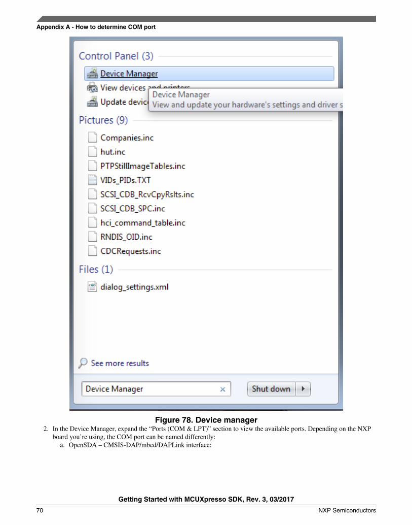
Figure 78. Device manager2. In the Device Manager, expand the “Ports (COM & LPT)” section to view the available ports. Depending on the NXP
board you’re using, the COM port can be named differently:a. OpenSDA – CMSIS-DAP/mbed/DAPLink interface:
Appendix A - How to determine COM port
Getting Started with MCUXpresso SDK, Rev. 3, 03/2017
70 NXP Semiconductors

Figure 79. OpenSDA – CMSIS-DAP/mbed/DAPLink interfaceb. OpenSDA – P&E Micro:
Figure 80. OpenSDA – P&E Micro
c. OpenSDA – J-Link:
Figure 81. OpenSDA – J-Linkd. P&E Micro OSJTAG:
Figure 82. P&E Micro OSJTAG
10 Appendix B - Default debug interfacesThe MCUXpresso SDK supports various hardware platforms that come loaded with a variety of factory programmed debuginterface configurations. The following table lists the hardware platforms supported by the MCUXpresso SDK, their defaultdebug interface, and any version information that helps differentiate a specific interface configuration.
All recent and future NXP hardware platforms support the configurable OpenSDA standard.
NOTEThe 'OpenSDA details' row of the following table is not applicable to LPC.
Table 1. Hardware platforms supported by MCUXpresso SDK
Hardware platform Default interface OpenSDA details
FRDM-K22F CMSIS-DAP/mbed/DAPLink OpenSDA v2.1
FRDM-K28F DAPLink OpenSDA v2.1
FRDM-K64F CMSIS-DAP/mbed/DAPLink OpenSDA v2.0
FRDM-K66F J-Link OpenSDA OpenSDA v2.1
FRDM-K82F CMSIS-DAP OpenSDA v2.1
FRDM-KE15Z DAPLink OpenSDA v2.1
FRDM-KL02Z P&E Micro OpenSDA OpenSDA v1.0
FRDM-KL03Z P&E Micro OpenSDA OpenSDA v1.0
FRDM-KL25Z P&E Micro OpenSDA OpenSDA v1.0
Table continues on the next page...
Appendix B - Default debug interfaces
Getting Started with MCUXpresso SDK, Rev. 3, 03/2017
NXP Semiconductors 71

Table 1. Hardware platforms supported by MCUXpresso SDK (continued)
FRDM-KL26Z P&E Micro OpenSDA OpenSDA v1.0
FRDM-KL27Z P&E Micro OpenSDA OpenSDA v1.0
FRDM-KL28Z P&E Micro OpenSDA OpenSDA v2.1
FRDM-KL43Z P&E Micro OpenSDA OpenSDA v1.0
FRDM-KL46Z P&E Micro OpenSDA OpenSDA v1.0
FRDM-KL81Z CMSIS-DAP OpenSDA v2.0
FRDM-KL82Z CMSIS-DAP OpenSDA v2.0
FRDM-KV10Z CMSIS-DAP OpenSDA v2.1
FRDM-KV31F P&E Micro OpenSDA OpenSDA v1.0
FRDM-KW24 CMSIS-DAP/mbed/DAPLink OpenSDA v2.1
FRDM-KW41Z CMSIS-DAP/DAPLink OpenSDA v2.1 or greater
FRDM-KW41Z CMSIS-DAP/DAPLink OpenSDA v2.1 or greater
Hexiwear CMSIS-DAP/mbed/DAPLink OpenSDA v2.0
MAPS-KS22 J-Link OpenSDA OpenSDA v2.0
TWR-K21D50M P&E Micro OSJTAG N/AOpenSDA v2.0
TWR-K21F120M P&E Micro OSJTAG N/A
TWR-K22F120M P&E Micro OpenSDA OpenSDA v1.0
TWR-K24F120M CMSIS-DAP/mbed OpenSDA v2.1
TWR-K60D100M P&E Micro OSJTAG N/A
TWR-K64D120M P&E Micro OpenSDA OpenSDA v1.0
TWR-K65D180M P&E Micro OpenSDA OpenSDA v1.0
TWR-K65D180M P&E Micro OpenSDA OpenSDA v1.0
TWR-KV10Z32 P&E Micro OpenSDA OpenSDA v1.0
TWR-K80F150M CMSIS-DAP OpenSDA v2.1
TWR-K81F150M CMSIS-DAP OpenSDA v2.1
TWR-KE18F DAPLink OpenSDA v2.1
TWR-KL28Z72M P&E Micro OpenSDA OpenSDA v2.1
TWR-KL43Z48M P&E Micro OpenSDA OpenSDA v1.0
TWR-KL81Z72M CMSIS-DAP OpenSDA v2.0
TWR-KL82Z72M CMSIS-DAP OpenSDA v2.0
TWR-KM34Z75M P&E Micro OpenSDA OpenSDA v1.0
TWR-KV10Z32 P&E Micro OpenSDA OpenSDA v1.0
TWR-KV11Z75M P&E Micro OpenSDA OpenSDA v1.0
TWR-KV31F120M P&E Micro OpenSDA OpenSDA v1.0
TWR-KV46F150M P&E Micro OpenSDA OpenSDA v1.0
TWR-KV58F220M CMSIS-DAP OpenSDA v2.1
TWR-KW24D512 P&E Micro OpenSDA OpenSDA v1.0
USB-KW24D512 N/A External probe N/A
USB-KW41Z CMSIS-DAP\DAPLink OpenSDA v2.1 or greater
USB-KW41Z CMSIS-DAP\DAPLink OpenSDA v2.1 or greater
Table continues on the next page...
Appendix B - Default debug interfaces
Getting Started with MCUXpresso SDK, Rev. 3, 03/2017
72 NXP Semiconductors

Table 1. Hardware platforms supported by MCUXpresso SDK (continued)
USB-KW41Z CMSIS-DAP\DAPLink OpenSDA v2.1 or greater
LPCXpresso54114 CMSIS-DAP N/A
LPCXpresso54608 CMSIS-DAP N/A
LPCXpresso54S618 CMSIS-DAP N/A
11 Appendix C - Updating debugger firmware
11.1 Updating OpenSDA firmware
Any NXP hardware platform that comes with an OpenSDA-compatible debug interface has the ability to update theOpenSDA firmware. This typically means switching from the default application (either CMSIS-DAP/mbed/DAPLink orP&E Micro) to a SEGGER J-Link. This section contains the steps to switch the OpenSDA firmware to a J-Link interface.However, the steps can be applied to also restoring the original image.
For reference, OpenSDA firmware files can be found at the links below:• J-Link: Download appropriate image from www.segger.com/opensda.html. Chose the appropriate J-Link binary based
on the table in Appendix B. Any OpenSDA v1.0 interface should use the standard OpenSDA download (in otherwords, the one with no version). For OpenSDA 2.0 or 2.1, select the corresponding binary.
• CMSIS-DAP/mbed/DAPLink: This interface is provided to support the ARM mbed initiative. Navigate todeveloper.mbed.org/platforms and select your hardware platform. On the specific platform/board page, there is a link tothe firmware image and instructions on how to load it, though the instructions are the same as below.
• P&E Micro: Downloading P&E Micro OpenSDA firmware images requires registration with P&E Micro(www.pemicro.com ).
These steps show how to update the OpenSDA firmware on your board for Windows operating system and Linux OS users:.
1. Unplug the board's USB cable.2. Press the board's "Reset" button. While still holding the button, plug the board back in to the USB cable.3. When the board re-enumerates, it shows up as a disk drive called "BOOTLOADER".
Appendix C - Updating debugger firmware
Getting Started with MCUXpresso SDK, Rev. 3, 03/2017
NXP Semiconductors 73

Figure 83. BOOTLOADER drive4. Drag the new firmware image onto the BOOTLOADER drive in Windows operating system Explorer, similar to how
you would drag and drop a file onto a normal USB flash drive.
NOTEIf for any reason the firmware update fails, the board can always re-enterbootloader mode by holding down the "Reset" button and power cycling.
These steps show how to update the OpenSDA firmware on your board for Mac OS users.
1. Unplug the board's USB cable.2. Press the board's "Reset" button. While still holding the button, plug the board back in to the USB cable.3. For boards with OpenSDA v2.0 or v2.1, it shows up as a disk drive called "BOOTLOADER" in Finder. Boards with
OpenSDA v1.0 may or may not show up depending on the bootloader version. If you see the drive in Finder, proceed tothe next step. If you do not see the drive in Finder, use a PC with Windows® OS 7 or an earlier version to either updatethe OpenSDA firmware, or update the OpenSDA bootloader to version 1.11 or later. The bootloader update instructionsand image can be obtained from P&E Microcomputer website.
4. For OpenSDA v2.1 and OpenSDA v1.0 (with bootloader 1.11 or later) users, drag the new firmware image onto theBOOTLOADER drive in Finder, similar to how you would drag and drop the file onto a normal USB Flash drive.
5. For OpenSDA v2.0 users, type these commands in a Terminal window:
> sudo mount -u -w -o sync /Volumes/BOOTLOADER > cp -X <path to update file> /Volumes/BOOTLOADER
NOTEIf for any reason the firmware update fails, the board can always re-enterbootloader mode by holding down the "Reset" button and power cycling.
11.2 Updating LPCXpresso board firmware
The LPCXpresso hardware platform comes with a CMSIS-DAP-compatible debug interface that has the ability to update thedebugger firmware. This typically means switching from the default application (CMSIS-DAP) to a SEGGER J-Link. Thissection contains the steps to switch the CMSIS-DAP firmware to a J-Link interface. However, the steps can also be applied torestoring the original image.
Appendix C - Updating debugger firmware
Getting Started with MCUXpresso SDK, Rev. 3, 03/2017
74 NXP Semiconductors
NOTEIf LPCXpresso IDE is used and the jumper making DFUlink is installed on the board(JP5 on some boards, but consult the board user manual or schematic for specific jumpernumber), Link2 debug probe boots to DFU mode, and LPCXpresso IDE automaticallydownloads the CMSIS-DAP firmware to the probe before flash memory programming(after clicking the "Debug" button). Using DFU mode ensures most up-to-date/compatible firmware is used with LPCXpresso IDE.
NXP provides the LCPScrypt utility, which is the recommended tool for programming the latest versions of CMSIS-DAPand J-Link firmware onto LPC-Link2 or LPCXpresso boards. The utility can be downloaded from www.nxp.com/lpcutilities.
These steps show how to update the debugger firmware on your board for Windows operating system. For Linux OS, followthe instructions described in LPCScrypt user guide (www.nxp.com/lpcutilities, select LPCScrypt, then select documentationtab).
1. Install the LPCScript utility.2. Unplug the board's USB cable.3. For LPCXpresso board: make DFU link (install the jumper labelled DFUlink).4. Connect the probe to the host via USB (use Link USB connector).5. Open a command shell and call the appropriate script located in the LPCScrypt installation directory (<LPCScrypt
install dir>).a. To program CMSIS-DAP debug firmware: <LPCScrypt install dir>/scripts/program_CMSISb. To program J-Link debug firmware: <LPCScrypt install dir>/scripts/program_JLINK
6. Remove DFU link (remove the jumper installed in step 3).7. Re-power the board by removing the USB cable and plugging it again.
12 Revision history
This table summarizes revisions to this document.
Table 2. Revision history
Revision number Date Substantive changes
3 03/2017 MCUXpresso SDK
2 08/2016 Added Chapter 8 and updated Section5.5
1 06/2016 Added Section 5.5 related to the NewProject Wizard for KSDK 2.0.0
0 01/2016 Initial release
Revision history
Getting Started with MCUXpresso SDK, Rev. 3, 03/2017
NXP Semiconductors 75

How to Reach Us:
Home Page:nxp.com
Web Support:nxp.com/support
Information in this document is provided solely to enable system and software
implementers to use NXP products. There are no express or implied copyright
licenses granted hereunder to design or fabricate any integrated circuits based
on the information in this document. NXP reserves the right to make changes
without further notice to any products herein.
NXP makes no warranty, representation, or guarantee regarding the suitability of
its products for any particular purpose, nor does NXP assume any liability arising
out of the application or use of any product or circuit, and specifically disclaims
any and all liability, including without limitation consequential or incidental
damages. “Typical” parameters that may be provided in NXP data sheets and/or
specifications can and do vary in different applications, and actual performance
may vary over time. All operating parameters, including “typicals,” must be
validated for each customer application by customerʼs technical experts. NXP
does not convey any license under its patent rights nor the rights of others. NXP
sells products pursuant to standard terms and conditions of sale, which can be
found at the following address: nxp.com/SalesTermsandConditions.
NXP, the NXP logo, Freescale, the Freescale logo, and Kinetis are trademarks
of NXP B.V. All other product or service names are the property of their
respective owners. ARM, ARM Powered, and Cortex are registered trademarks
of ARM Limited (or its subsidiaries) in the EU and/or elsewhere. All rights
reserved.
© 2017 NXP B.V.
Document Number MCUXSDKGSUGRevision 3, 03/2017