
GeoVenturing-LNT 4/12/2008 2:14 PMfuturethought.pbworks.com/f/WFS2007-FMEA_I35W... · Primary...
26
Bob-RJ Burkhart :: LCDR, USNR-Ret. Page 1 of 264/12/2008Bob-RJ Burkhart :: LCDR, USNR-Ret. How to cite this article: Microsoft® Student 2008 [DVD]. Redmond, WA: Microsoft Corporation, 2007. Microsoft ® Encarta ® 2008. © 1993-2007 Microsoft Corporation. All rights reserved. GeoVenturing-LNT 4/12/2008 2:14 PM Understanding INTERdependence using Failure Mode and Effects Analysis (FMEA) : The effects of these pollutants may be immediate or delayed. Primary effects of pollution occur immediately after contamination occurs, such as the death of marine plants and wildlife after an oil spill at sea. Secondary effects may be delayed or may persist in the environment into the future, perhaps going unnoticed for many years. DDT, a nondegradable compound, seldom poisons birds immediately, but gradually accumulates in their bodies. Birds with high concentrations of this pesticide lay thin-shelled eggs that fail to hatch or produce deformed offspring. These secondary effects, publicized by Rachel Carson in her 1962 book, Silent Spring, threatened the survival of species such as the bald eagle and peregrine falcon, and aroused public concern over the hidden effects of nondegradable chemical compounds. I. INTRODUCTION II. IMPACTS OF POLLUTION III. TYPES OF POLLUTION A. Air Pollution B. Water Pollution C. Soil Pollution D. Solid Waste
Transcript of GeoVenturing-LNT 4/12/2008 2:14 PMfuturethought.pbworks.com/f/WFS2007-FMEA_I35W... · Primary...

Bob-RJ Burkhart :: LCDR, USNR-Ret. Page 1 of 264/12/2008Bob-RJ Burkhart :: LCDR, USNR-Ret.
How to cite this article:
Microsoft® Student 2008 [DVD]. Redmond, WA: Microsoft Corporation, 2007.
Microsoft ® Encarta ® 2008. © 1993-2007 Microsoft Corporation. All rights reserved.
GeoVenturing-LNT4/12/2008 2:14 PM
Understanding INTERdependence using Failure Mode and Effects Analysis (FMEA):
The effects of these pollutants may be immediate or delayed. Primary effects of pollutionoccur immediately after contamination occurs, such as the death of marine plants andwildlife after an oil spill at sea.
Secondary effects may be delayed or may persist in the environment into the future,perhaps going unnoticed for many years. DDT, a nondegradable compound, seldompoisons birds immediately, but gradually accumulates in their bodies. Birds withhigh concentrations of this pesticide lay thin-shelled eggs that fail to hatch orproduce deformed offspring.
These secondary effects, publicized by Rachel Carson in her 1962 book, SilentSpring, threatened the survival of species such as the bald eagle and peregrinefalcon, and aroused public concern over the hidden effects of nondegradablechemical compounds.
I.
INTRODUCTION
II.
IMPACTS OF POLLUTION
III.
TYPES OF POLLUTION
A.
Air Pollution
B.
Water Pollution
C.
Soil Pollution
D.
Solid Waste

Bob-RJ Burkhart :: LCDR, USNR-Ret. Page 2 of 264/12/2008Bob-RJ Burkhart :: LCDR, USNR-Ret.
E.
Hazardous Waste
F.
Noise Pollution
IV.
HISTORY
V.
CONTROLLING POLLUTION
MORE SOURCES
Web Links
EPA: US Environmental Protection AgencyThe Environmental Protection Agency home page contains its rules and regulations,recent press releases, and information about its testing methods and programs.http://www.epa.gov/
Noise Pollution ClearinghouseThe Noise Pollution Clearinghouse, a national nonprofit organization,offers news and information about noise control.http://www.nonoise.org/
Chemical ScorecardThe Environmental Defense Fund provides searchable chemical pollutants information,including a tool that locates community polluters by zip code.http://www.scorecard.org/
Further Reading
For younger readers
Air pollution
Water pollution
Primary Sources
Historic Headlines
Contributed By:
Paul Engelking
Microsoft ® Encarta ® 2008. © 1993-2007 Microsoft Corporation. All rights reserved.

Bob-RJ Burkhart :: LCDR, USNR-Ret. Page 3 of 264/12/2008Bob-RJ Burkhart :: LCDR, USNR-Ret.
The collapse of the Interstate 35W bridge in downtown Minneapolis, Minnesota, in 2007was the most recent major bridge disaster. The Minneapolis bridge collapse raisedrenewed concerns about bridge safety in the United States.
It followed a report issued in 2006 by the Federal Highway Administration ranking13 percent of U.S. bridges as “structurally deficient” and almost 14 percent as“functionally obsolete.”
Schultz, B. Cameron, and Grivas, Dimitri A. "Bridge (structure)."
Bridge (structure)I INTRODUCTION
Collapse of the Tacoma Narrows Bridge
The original Tacoma Narrows Bridge stretched 1,810 m (5,940 ft) across a narrow channel of Puget
Sound near Tacoma, Washington. After two years of construction, the bridge opened to traffic on July
1, 1940. Four months later the bridge collapsed during a windstorm with gusts that reached 68 km/h
(42 mph). The catastrophe was attributed to faulty design. Instead of allowing the wind to pass
through, the suspended girders caught the wind, causing the bridge to buck and roll. The bucking
motion earned the bridge the nickname Galloping Gertie. The stronger the wind blew, the more
violently the structure oscillated, until it finally broke apart and crashed into the water. In 1992 the
bridge’s sunken remains were placed on the United States National Register of Historic Places.
Archive Photos
Bridge (structure), structure designed to provide continuous passage over an obstacle. Bridges
commonly carry highways, railroad lines, and pathways over obstacles such as waterways, deep
valleys, and other transportation routes. Bridges may also carry water, support power cables, or
house telecommunications lines.
Bob-RJ Burkhart :: LCDR, USNR-Ret. Page 4 of 264/12/2008Bob-RJ Burkhart :: LCDR, USNR-Ret.
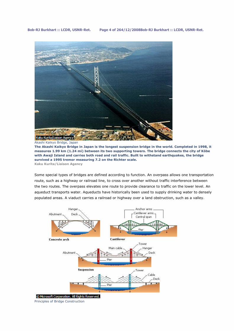
Akashi Kaikyo Bridge, Japan
The Akashi Kaikyo Bridge in Japan is the longest suspension bridge in the world. Completed in 1998, it
measures 1.99 km (1.24 mi) between its two supporting towers. The bridge connects the city of Kōbe
with Awaji Island and carries both road and rail traffic. Built to withstand earthquakes, the bridge
survived a 1995 tremor measuring 7.2 on the Richter scale.
Kaku Kurita/Liaison Agency
Some special types of bridges are defined according to function. An overpass allows one transportation
route, such as a highway or railroad line, to cross over another without traffic interference between
the two routes. The overpass elevates one route to provide clearance to traffic on the lower level. An
aqueduct transports water. Aqueducts have historically been used to supply drinking water to densely
populated areas. A viaduct carries a railroad or highway over a land obstruction, such as a valley.
Principles of Bridge Construction

Bob-RJ Burkhart :: LCDR, USNR-Ret. Page 5 of 264/12/2008Bob-RJ Burkhart :: LCDR, USNR-Ret.
A bridge must be strong enough to support its own weight as well as the weight of the vehicles and
people that use it. It must also be able to resist varying environmental conditions. Different designs
serve different purposes and lengths of spans. Load is transferred by hangers (arch bridges) or cables
(suspension and cable-stayed bridges) to towers or abutments at the ends of the bridge, and these in
turn transfer the force into the ground. Cantilever bridges have two independent cantilever arms
projecting toward each other and joined by a central span.
© Microsoft Corporation. All Rights Reserved.
The earliest bridges were simple structures created by spanning a gap with timber or rope. Designs
became more complex as builders developed new construction methods and discovered better
materials. The stone arch was the first major advance in bridge design. It was used by the ancient
Greeks, Etruscans, and Chinese (see Arch and Vault). The Romans perfected arch design, using arches
to build massive stone bridges throughout the Roman Empire. Stone arch construction remained the
premier bridge design until the introduction of the steam locomotive in the early 19th century.
Golden Gate Bridge, San Francisco
The Golden Gate Bridge links the city of San Francisco with Marin County to the north. The suspension
bridge was opened in 1937 and since then has been one of the principal landmarks of both San
Francisco and California.
Michael J. Howell/ProFiles West
Between 1830 and 1880, as railroad building expanded throughout the world, bridge design and
construction also evolved to carry these heavy vehicles over new obstacles. Designers experimented
with a wide variety of bridge types and materials to meet the demand for greater heights, spans, and
strength. Locomotives were heavier and moved faster than anything before, requiring stronger
bridges. The basic beam bridge, a simple beam over a span, was strengthened by adding support
piers underneath and by reinforcing the structure with elaborate scaffolding called a truss. During the
period of railroad expansion, iron trusses replaced stone arches as the preferred design for large
bridges.

Bob-RJ Burkhart :: LCDR, USNR-Ret. Page 6 of 264/12/2008Bob-RJ Burkhart :: LCDR, USNR-Ret.
Verrazano-Narrows Bridge
An overview of the Verrazano-Narrows steel suspension bridge reveals the structure and cable system
that allows it to support weight over an extended span. The bridge links Brooklyn and Staten Island at
the entrance of New York Harbor, crossing 1,298 m (4,260 ft) of water. Cable systems often rise
hundreds of meters above the roadway; at the peak of its towers the Verrazano-Narrows is 210 m (690
ft) tall. More than 135,000 metric tons (150,000 U.S. tons) of steel were used in the bridge, which cost
$325 million to build.
Frederica Georgia/Photo Researchers, Inc.
In 1855 British inventor Sir Henry Bessemer developed a practical process for converting cast iron into
steel (see Iron and Steel Manufacture). This process increased the availability of steel and lowered
production costs considerably. The strength and lightness of steel revolutionized bridge building. In
the late 19th century and the first half of the 20th century, many large-scale steel suspension bridges
were constructed over major waterways. Also in the late 19th century, engineers began to experiment
with concrete reinforced with steel bars for added strength. More recently, reinforced concrete has
been combined with steel girders, which are solid beams that extend across a span. When the
Interstate Highway System in the United States and similar road systems in other countries were
constructed in the mid- to late 20th century, the steel-and-concrete girder bridge was one of the most
commonly used bridge designs. The last three decades of the 20th century saw a period of large-scale
bridge building in Europe and Asia. Current research focuses on using computers, instrumentation,
automation, and new materials to improve bridge design, construction, and maintenance.
II TYPES OF BRIDGES
Bridge designs differ in the way they support loads. These loads include the weight of the bridges
themselves, the weight of the material used to build the bridges, and the weight and stresses of the
vehicles crossing them. There are basically eight common bridge designs: beam, cantilever, arch,
truss, suspension, cable-stayed, movable, and floating bridges. Combination bridges may incorporate
two or more of the above designs into a bridge. Each design differs in appearance, construction
methods and materials used, and overall expense. Some designs are better for long spans. Beam
bridges typically span the shortest distances, while suspension and cable-stayed bridges span the
greatest distances.
A Beam Bridges
Bob-RJ Burkhart :: LCDR, USNR-Ret. Page 7 of 264/12/2008Bob-RJ Burkhart :: LCDR, USNR-Ret.
Beam bridges represent the simplest of all bridge designs. A beam bridge consists of a rigid horizontal
member called a beam that is supported at both ends, either by a natural land structure, such as the
banks of a river, or by vertical posts called piers. Beam bridges are the most commonly used bridges
in highway construction. Single-piece, rolled-steel beams can support spans of 15 to 30 m (50 to 100
ft). Heavier, reinforced beams and girders are used for longer spans.
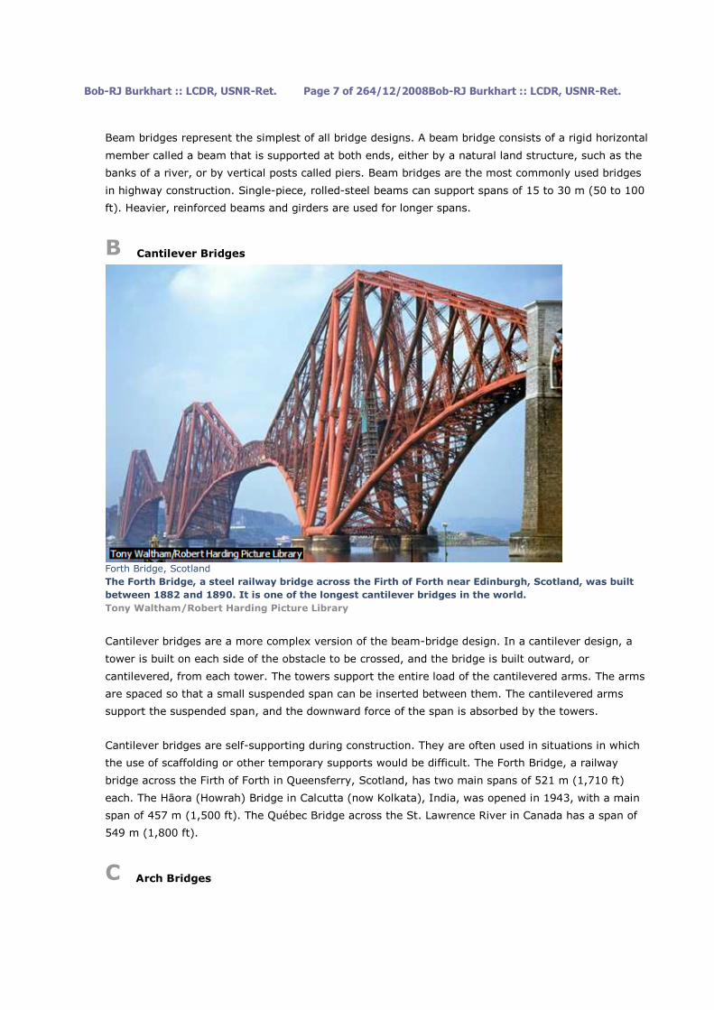
B Cantilever Bridges
Forth Bridge, Scotland
The Forth Bridge, a steel railway bridge across the Firth of Forth near Edinburgh, Scotland, was built
between 1882 and 1890. It is one of the longest cantilever bridges in the world.
Tony Waltham/Robert Harding Picture Library
Cantilever bridges are a more complex version of the beam-bridge design. In a cantilever design, a
tower is built on each side of the obstacle to be crossed, and the bridge is built outward, or
cantilevered, from each tower. The towers support the entire load of the cantilevered arms. The arms
are spaced so that a small suspended span can be inserted between them. The cantilevered arms
support the suspended span, and the downward force of the span is absorbed by the towers.
Cantilever bridges are self-supporting during construction. They are often used in situations in which
the use of scaffolding or other temporary supports would be difficult. The Forth Bridge, a railway
bridge across the Firth of Forth in Queensferry, Scotland, has two main spans of 521 m (1,710 ft)
each. The Hāora (Howrah) Bridge in Calcutta (now Kolkata), India, was opened in 1943, with a main
span of 457 m (1,500 ft). The Québec Bridge across the St. Lawrence River in Canada has a span of
549 m (1,800 ft).
C Arch Bridges

Bob-RJ Burkhart :: LCDR, USNR-Ret. Page 8 of 264/12/2008Bob-RJ Burkhart :: LCDR, USNR-Ret.
Iron Rail Bridge
An early iron arch bridge supporting a railway spans the Adda River in northern Italy. The arch makes
use of truss framework to help support the bridge.
Danilo Donadoni/Bruce Coleman, Inc.
Arch bridges are characterized by their stability. In an arch, the force of the load is carried outward
from the top to the ends of the arch, where abutments keep the arch ends from spreading apart. Arch
bridges have been constructed of stone, brick, timber, cast iron, steel, and reinforced concrete.
Masonry Arch Bridge
This railroad bridge near Harrisburg, Pennsylvania, has cut stones arranged in a semicircular arch
construction. Masonry arch bridges have largely been replaced by steel and concrete arch bridges
because masonry bridges are more expensive to build.
Blair Seitz/Photo Researchers, Inc.
Steel and concrete arches are particularly well suited for bridging ravines or chasms with steep, solid
walls. The New River Gorge Bridge in West Virginia is the longest arch bridge, spanning a gap of 518
m (1,700 ft). Other long arch bridges include the Bayonne Bridge between New York and New Jersey,
and the Sydney Harbour Bridge in Australia, with main spans of 504 m (1,652 ft) and 503 m (1,650
ft), respectively.

Bob-RJ Burkhart :: LCDR, USNR-Ret. Page 9 of 264/12/2008Bob-RJ Burkhart :: LCDR, USNR-Ret.
D Truss Bridges
Astoria Bridge
Constructed of continuous trusses, this interstate bridge over the meandering Columbia River connects
Astoria, Oregon, to Megler, Washington. The bridge was named for Fort Astor, a fur-trading post
established in 1811 by John Jacob Astor's Pacific Fur Company.
Jim Corwin
Truss bridges utilize strong, rigid frameworks that support these bridges over a span. Trusses are
created by fastening beams together in a triangular configuration. The truss framework distributes the
load of the bridge so that each beam shares a portion of the load. Beam, cantilever, and arch bridges
may be constructed of trusses. Truss bridges can carry heavy loads and are relatively lightweight.
They are also inexpensive to build. The Astoria Bridge over the Columbia River in Oregon has a span
of 376 m (1,232 ft).
E Suspension Bridges

Bob-RJ Burkhart :: LCDR, USNR-Ret. Page 10 of 264/12/2008Bob-RJ Burkhart :: LCDR, USNR-Ret.
Clifton Bridge
Suspension bridges, like the Clifton Suspension Bridge in Bristol, England, are commonly used in areas
where building a bridge with mid-span supports would be either extremely difficult or overly
expensive. The span hangs from two enormous main cables, eliminating the need to bolster the span
from underneath. In turn, the main cables place their load on the towers at each end of the bridge, and
on the points where the cables are attached to the ground beyond each of the towers.
Sarah Ellis/Hutchison Library
Suspension bridges consist of two large, or main, cables that are hung (suspended) from towers. The
main cables of a suspension bridge drape over two towers, with the cable ends buried in enormous
concrete blocks known as anchorages. The roadway is suspended from smaller vertical cables that
hang down from the main cables. In some cases, diagonal cables run from the towers to the roadway
and add rigidity to the structure. The main cables support the weight of the bridge and transfer the
load to the anchorages and the towers.
Bob-RJ Burkhart :: LCDR, USNR-Ret. Page 11 of 264/12/2008Bob-RJ Burkhart :: LCDR, USNR-Ret.
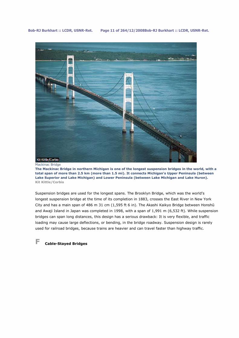
Mackinac Bridge
The Mackinac Bridge in northern Michigan is one of the longest suspension bridges in the world, with a
total span of more than 2.5 km (more than 1.5 mi). It connects Michigan’s Upper Peninsula (between
Lake Superior and Lake Michigan) and Lower Peninsula (between Lake Michigan and Lake Huron).
Kit Kittle/Corbis
Suspension bridges are used for the longest spans. The Brooklyn Bridge, which was the world’s
longest suspension bridge at the time of its completion in 1883, crosses the East River in New York
City and has a main span of 486 m 31 cm (1,595 ft 6 in). The Akashi Kaikyo Bridge between Honshū
and Awaji Island in Japan was completed in 1998, with a span of 1,991 m (6,532 ft). While suspension
bridges can span long distances, this design has a serious drawback: It is very flexible, and traffic
loading may cause large deflections, or bending, in the bridge roadway. Suspension design is rarely
used for railroad bridges, because trains are heavier and can travel faster than highway traffic.
F Cable-Stayed Bridges

Bob-RJ Burkhart :: LCDR, USNR-Ret. Page 12 of 264/12/2008Bob-RJ Burkhart :: LCDR, USNR-Ret.
Normandy Bridge
Normandy Bridge near Le Havre, France, is one of the world’s longest cable-stayed suspension bridges,
with a main span of 856 m (2808 ft). The bridge opened to traffic in January 1995. Unlike conventional
suspension bridges, which use two massive cables, cable-stayed bridges employ numerous smaller
cables attached to two large towers or pylons.
REUTERS/THE BETTMANN ARCHIVE
Cable-stayed bridges represent a variation of the suspension bridge. Cable-stayed bridges have tall
towers like suspension bridges, but in a cable-stayed bridge, the roadway is attached directly to the
towers by a series of diagonal cables. A cable-stayed bridge is constructed in much the same way as a
suspension bridge is, but without the main cables.
Millau Viaduct

Bob-RJ Burkhart :: LCDR, USNR-Ret. Page 13 of 264/12/2008Bob-RJ Burkhart :: LCDR, USNR-Ret.
The spectacular Millau Viaduct soars above the valley of the Tarn River near Millau in southwestern
France. The 2.5 km- (1.5 mi-) long cable-stayed structure is the highest vehicular bridge in the world,
with the road surface reaching a maximum height of 270 m (885 ft) above the valley floor. The
viaduct's tallest pier rises to a height of more than 340 m (1,115 ft). The viaduct opened to traffic in
December 2004.
Chris Hellier/Corbis
Cable-stayed designs are used for intermediate-length spans. Advantages a cable-stayed bridge has
over a standard suspension bridge include speed of construction and lower cost, since anchorages are
not necessary. There are no massive cables, as with suspension bridges, making cable repair or
replacement simpler. The Pont de Normandie (Normandy Bridge) over the Seine River near Le Havre
in France opened in 1995, with a span length of 856 m (2,808 ft).
G Movable Bridges
London Tower Bridge
The 244-m (800-ft) London Tower Bridge spans the Thames River in London. It was the only movable
bridge crossing the Thames when it was completed in 1894. Sir Horace Jones designed the bridge, and
Sir John Wolfe Barry built it.
SIME/Ripani Massimo /4Corners Images
Movable bridges make up a class of bridge in which a portion of the bridge moves up or swings out to
provide additional clearance beneath the bridge. Movable bridges are usually found over heavily
traveled waterways. The three most common types of movable bridge are the bascule (drawbridge),
vertical-lift, and swing bridges. Modern bascule bridges usually have two movable spans that rise
upward, opening in the middle. A vertical-lift bridge consists of a rigid deck frame held between two
tall towers. The bridge opens by hoisting the entire bridge roadway upward between the towers in an

Bob-RJ Burkhart :: LCDR, USNR-Ret. Page 14 of 264/12/2008Bob-RJ Burkhart :: LCDR, USNR-Ret.
elevator-like fashion. Swing bridges are mounted on a central pier and open by swinging to one side,
allowing ships to pass.
Bascule Bridge
A bascule bridge on the Miami River in Florida is open to let a ship pass. Bascule bridges are useful for
spanning short distances over busy waterways, and they allow ships of any height to pass underneath.
Morton Beebe-S.F./Corbis
Movable bridges are generally constructed over waterways where it is either impractical or too costly
to build bridges with high enough clearances for water traffic to pass underneath. Bascule bridges are
used for short spans. A bascule bridge over the Black River in Lorain, Ohio, has a length of 102 m
(333 ft). Vertical-lift bridges are useful for longer spans, but they must be built so they can be lifted
high enough for tall ships to pass underneath. The vertical-lift bridge over Arthur Kill between Staten
Island in New York City and New Jersey has a span of 170 m (558 ft) and can be raised 41 m (135 ft)
above the water. Swing bridges have the advantage of not limiting the height of passing vessels, but
they do restrict the horizontal clearance, or width, of passing ships. The longest swing-bridge span is
that of a railroad and highway bridge crossing the Mississippi River at Fort Madison, Iowa. This bridge
has a span of 166 m (545 ft).
H Floating Bridges

Bob-RJ Burkhart :: LCDR, USNR-Ret. Page 15 of 264/12/2008Bob-RJ Burkhart :: LCDR, USNR-Ret.
Floating Bridge
The simple pontoon floating bridge over the Kābul River, Pakistan, is supported by flat-bottomed boats
rather than fixed piers. Pontoon bridges may also be supported by other types of floats or metal
cylinders.
Robert Harding Picture Library
Floating bridges are formed by fastening together sealed, floating containers called pontoons and
placing a roadbed on top of them. A pontoon typically contains many compartments so that if a leak
occurs in one compartment, the pontoon will not sink. Some floating bridges are constructed using
boats or other floating devices rather than pontoons.
Floating bridges were originally developed and are most widely used as temporary structures for
military operations. For everyday use, floating bridges are popular when deep water, bad riverbed
conditions, or other conditions make it difficult to construct traditional bridge piers and foundations. A
concrete-pontoon bridge carries a highway across Lake Washington, near Seattle, Washington. It
consists of 25 floating sections bolted together and anchored in place and a span that can be opened
to permit the passage of large ships. The floating section of the bridge is 2.3 km (1.4 mi) long.
I Combination Bridges

Bob-RJ Burkhart :: LCDR, USNR-Ret. Page 16 of 264/12/2008Bob-RJ Burkhart :: LCDR, USNR-Ret.
Chesapeake Bay Bridge-Tunnel
Chesapeake Bay features a piece of construction that may startle unprepared travelers. The 28.2 km
(17.5 mi) crossing between Norfolk and Cape Charles, Virginia, begins as a bridge, but disappears into
the water midway. A combination structure, the Chesapeake Bay Bridge-Tunnel combines two bridges
with two tunnels that pass under major shipping channels.
Chesapeake Bay Bridge and Tunnel District
Combination bridges include crossings consisting of several types of bridges or both bridges and
tunnels. For example, the Chesapeake Bay Bridge-Tunnel in Virginia includes two tunnels that are
each 1.6 km (1.0 mi) long along its 28 km (17 mi) length from shore to shore. The Triborough Bridge
in New York City is actually a network of bridges connecting the boroughs of Queens, Manhattan, and
the Bronx. These bridges meet over Randall’s Island. Seven truss spans stretch over Bronx Kills, and
three truss spans and a vertical lift extend over the Harlem River. A viaduct and a suspension bridge
also make up part of the Triborough Bridge.
III BRIDGE PLANNING AND CONSTRUCTION

Bob-RJ Burkhart :: LCDR, USNR-Ret. Page 17 of 264/12/2008Bob-RJ Burkhart :: LCDR, USNR-Ret.
Concrete Bridge
Modern bridge construction for the Gateway Bridge over the Brisbane River in Australia uses
lightweight and durable concrete reinforced with steel bars or mesh. Concrete is made from three
components: an aggregate material such as sand or gravel, water, and the binding agent, portland
cement.
Joyce Photographics/Photo Researchers, Inc.
New bridges are built either to replace old structures that no longer meet the demands of modern
traffic or to cross obstacles on a new transportation route. Old bridges are replaced when repairs
cannot be made economically or when traffic becomes too heavy for the old bridge. New
transportation routes are built when traffic levels have outgrown the capacity of existing routes or
simply to make it faster to get from one busy place to another. Often, new transportation routes are
part of government programs to promote regional economic development.
In the United States, state and local transportation agencies determine where new bridges are needed
and pay a small portion of the cost. The federal government usually pays for most of the construction
expense, using money generated from taxes. Bridges funded by tax dollars are used free of charge.
The few bridges for which a toll is charged to drivers for use are funded through the sale of bonds to
raise money for construction. The money collected from the toll is used to pay back the bonds. The
use of tolls and borrowing to finance bridge construction was more widespread in the past than it is
today.
A Design Selection
Engineers must consider several factors when designing a bridge. They consider the distance to be
crossed and the feature, such as a river, bay, or canyon, to be crossed. Engineers must anticipate the
type of traffic and the amount of load the bridge will have to carry and the minimum span and height
required for traffic traveling across and under the bridge. Temperature, environmental conditions, and
the physical nature of the building site (such as the geometry of the approaches, the strength of the

Bob-RJ Burkhart :: LCDR, USNR-Ret. Page 18 of 264/12/2008Bob-RJ Burkhart :: LCDR, USNR-Ret.
ground, and the depth to firm bedrock) also determine the best bridge design for a particular
situation.
Once engineers have the data they need in order to design a bridge, they create a work plan for
constructing it. Factors to be considered include availability of materials, equipment, and trained
labor; availability of workshop facilities; and local transportation to the site. These factors, in
combination with the funding and time available for bridge design and construction, are the major
requirements and constraints on design decisions for a particular site.
B Design Decisions
There are four basic categories of design decisions: the type of bridge, the materials of which it will be
made, the type of foundations that will support the structure, and the construction method to be used.
Typically, several feasible choices exist in each category, and each option is evaluated in terms of
convenience, appearance, endurance, and cost. Bridges must be convenient to build, use, and
maintain. Appearance is important in gaining public approval, which is particularly critical for
taxpayer-funded projects. Bridges must be designed to endure, as most structures can be expected to
provide service for at least 50 to 100 years. Durability of materials and maintenance requirements are
important considerations, as the true cost of a bridge is not simply the initial construction expense but
the total cost of constructing and maintaining the structure throughout its service life. Good designs
minimize total cost.
B1 Bridge Type
The bridge type (such as beam, arch, truss, and others) depends largely on the required dimensions
for the bridge and the type of traffic to be carried. The required length and clearances needed by
traffic are major considerations in bridge design. Many bridges are long enough to require several
intermediate supports, or piers. The location of piers is usually a crucial factor, whether in water or on
land.
B2 Materials
Materials historically used for bridge building include rope and other fibers, wood, stone and masonry,
iron, steel, and concrete. Fiber, timber, stone, and masonry are still used occasionally, but steel and
concrete are the materials used for most modern bridge building. Fiber rope is occasionally used for
short pedestrian bridges. Timber is perceived as a rustic material and is sometimes used in public
parks, on private property, or in other situations in which a natural or historic appearance is desirable.
The strength and durability of timber are quite limited compared to those of steel and concrete.
Therefore, timber is suitable only for short spans that carry minimal traffic loads. Stone and masonry
are sometimes used as facing materials on concrete and steel bridges, if appearance is important
enough to justify the additional expense.

Bob-RJ Burkhart :: LCDR, USNR-Ret. Page 19 of 264/12/2008Bob-RJ Burkhart :: LCDR, USNR-Ret.
When deciding between steel and concrete, designers evaluate the tradeoffs among weight, strength,
and expense to determine which material is best for a particular bridge. Concrete is heavier than steel,
but steel is much stronger. The major advantages of concrete are that it is considerably cheaper than
steel and can be formed into a greater variety of shapes. For short bridges, the weight of material is
not an important concern, and so concrete is an economical choice. However, as span increases, the
weight of the structure grows substantially, and greater strength is needed to support the overall
structure. Steel tends to be preferred for large bridges because less material has to be handled and
supported during the construction process.
The distinction between steel and concrete is not absolute, as most steel bridges have concrete decks,
and all concrete is reinforced with steel to provide greater tensile strength (resistance to pulling).
Reinforced concrete is made by pouring concrete mix over steel bars or mesh. The concrete and metal
bond as the mix hardens, producing a material in which the high tensile strength of steel is combined
with the great compressive strength (ability to resist pushing or squeezing) of concrete. An alternative
method of reinforcing concrete is prestressing. Prestressed concrete is made by pouring concrete over
stretched and anchored steel strands. After the concrete has set, the anchors are released. As the
steel tries to return to its original length, it compresses the concrete, resulting in a relatively
lightweight, extremely strong material.
B3 Foundations
All bridge piers rest on foundations that transfer loads from the bridge structure into the ground. The
foundations support the bridge, and their design is critical. Difficult conditions, such as deep water or
soft ground, can make foundation construction complicated and expensive. In such circumstances
designers may choose to decrease the number of piers by increasing span length. Of course, greater
span lengths often require a more expensive bridge type, and therefore the tradeoffs must be
evaluated carefully.
If the ground is very strong at a bridge site, a foundation is formed by pouring a simple concrete mat
beneath each of the piers. If the soil is weak, it may be excavated down to bedrock, and the piers can
then be built directly on the solid rock. Alternatively, a group of vertical posts, or piles, can be driven
through the soil to bedrock, and piers can be built on top of the piles.
B4 Construction Methods

Bob-RJ Burkhart :: LCDR, USNR-Ret. Page 20 of 264/12/2008Bob-RJ Burkhart :: LCDR, USNR-Ret.
Storebælt Bridge
After many delays and redesigns, the bridge over the Storebælt (Great Belt), a channel linking the
North and Baltic seas, opened to traffic in 1998. The bridge connects the Danish islands of Fyn and
Sjælland. With a main span of 1,624 m (5,328 ft), it is the second longest suspension bridge in the
world. Its twin concrete piers stand 254 m (833 ft) high. This photograph shows the bridge under
construction.
Rossi Xavier/Liaison Agency
Bridges are erected using a variety of construction methods. Some techniques are associated with a
particular bridge type, and care must be taken not to select a design that requires construction
methods unsuitable for the site. Concrete and steel bridges are generally built using similar
techniques, although concrete bridges are built in shorter sections than are steel bridges because of
the greater weight of the material.
One of the simplest construction methods for bridges is to assemble a span away from the bridge site
and then transport it to the site. The span can then be lifted into position as one piece. This method is
most often suitable for small truss bridges or for the suspended span of a cantilever truss. Another
approach is to use falsework, or temporary scaffolding, to support the incomplete parts of a bridge
before they are joined and able to support themselves.
The use of falsework is not always possible, owing to strong river currents, interference with river
traffic, or great distances to the ground. If falsework is impractical, bridges can be constructed by the
cantilever method. With this technique, a bridge is built piece by piece, with the entire structure
supported from the section previously completed. Thus, the structure is self-supported throughout the
entire construction process. The use of cantilever construction methods saves material and therefore
expense, but it is very complex, as great care must be taken not to unbalance the structure during
construction. Most arch bridges, and of course cantilever bridges, are built using cantilever methods.

Bob-RJ Burkhart :: LCDR, USNR-Ret. Page 21 of 264/12/2008Bob-RJ Burkhart :: LCDR, USNR-Ret.
The large towers and cable anchorages of suspension bridges are built without the use of falsework,
and then the suspension cables are spun. Many individual wires are draped over the towers and are
then squeezed together into a circular shape and clamped at intervals to create a main cable.
Suspension wires are dropped from the cables to support the roadway, and the roadway is completed.
For all bridge types, underwater foundations require unique construction methods. Builders use
cofferdams and caissons to obtain access to ground that is normally under water. A cofferdam is a
temporary watertight enclosure constructed on the spot where a pier is to be built. A cofferdam
usually consists of sheets of steel driven into the ground to create a walled chamber. The cofferdam is
then pumped dry to expose the riverbed. Soil can be excavated to bedrock, or piles can be driven to
create the pier foundation. The cofferdam is removed after the foundation and pier are constructed. A
caisson is a large cylinder or box chamber that is sunk into the riverbed. The excavation and
foundation work takes place within the submerged caisson. Some caissons are removed after
construction, while others are left in place, filled with concrete, and used as part of a permanent
foundation.
C Safety
In bridge design, engineers strive to plan an economical structure that will safely transmit loads to the
ground without collapsing or deforming excessively. Since it is difficult to predict the exact loading and
circumstances that a bridge must withstand, all bridge designs include a substantial margin of safety.
Design standards vary throughout the world, but all aim at ensuring that new bridges will provide
many years of service and will maintain an adequate margin of safety against failure. Of course, the
safety of a structure when it is first erected does not ensure that it will remain safe for all time. All
structures require both periodic inspection and proper maintenance to keep them safe.
Notable bridge failures include the collapse of the Firth of Tay Bridge in Scotland in 1879, the collapse
of the Québec Bridge in Canada while under construction in 1907, and the collapse of the Tacoma
Narrows Bridge, nicknamed Galloping Gertie, in Washington State in 1940. Other recent disasters in
which bridges collapsed due to structural or engineering failures rather than collisions or flooding
include the Mianus River Bridge in Greenwich, Connecticut, in 1982, the Seongsu Bridge collapse in
Seoul, South Korea, in 1994, and the collapse of a bridge in Lisbon, Portugal, in 2001. In 2002 there
were two major bridge collapses in China, and in 2006 a bridge collapsed in Laval, Canada.
The collapse of the Interstate 35W bridge in downtown Minneapolis, Minnesota, in 2007 was
the most recent major bridge disaster. The Minneapolis bridge collapse raised renewed
concerns about bridge safety in the United States. It followed a report issued in 2006 by the
Federal Highway Administration ranking 13 percent of U.S. bridges as “structurally deficient”
and almost 14 percent as “functionally obsolete.”
The National Transportation Safety Board (NTSB) concluded in 2008 that the Minneapolis bridge
collapse was due to a design flaw. The NTSB investigation found that a critical metal plate linking the
bridge’s girders was too thin to support weight added to the bridge over years of upgrades and
repairs. Known as a gusset plate, its use in the design of this and other bridges was in part due to its
lower cost.

Bob-RJ Burkhart :: LCDR, USNR-Ret. Page 22 of 264/12/2008Bob-RJ Burkhart :: LCDR, USNR-Ret.
The NTSB urged bridge inspectors to examine bridges for this design flaw, which it
characterized as a “fracture critical” flaw because there were no backup structures to prevent
a collapse if the gusset plate failed. In the case of the Minneapolis bridge, extra weight on the
bridge from a construction repair project at the time of the collapse added to the strain on the
gusset plate.
IV HISTORY
The different sizes and shapes of bridges encountered today reflect thousands of years of progress in
engineering, technology, and building materials.
A Early and Medieval Bridges
Ponte Vecchio, Florence, Italy
Many of the older bridges in Florence were destroyed during World War II; however, the Ponte Vecchio
(Old Bridge), built in 1345 and shown here, survived. Goldsmith and jewelry shops line the bridge.
Walter Rawlings/Robert Harding Picture Library
In ancient times, builders would throw a log across a stream or use two vines or ropes (the upper for
a handhold and the lower for a foothold) to create a crossing. The earliest rudimentary arches (built
from 4000 to 2000 BC) consisted of stones balanced on top of one another. The ancient Romans
perfected stone arch design and were the first to build large-scale bridges, many of which still stand
today. The largest remaining ancient Roman aqueduct, the Pont du Gard in southern France, is 270 m
(886 ft) long and consists of three tiers of semicircular stone arches. The Romans built the Pont du
Gard in the late 1st century BC or the early 1st century AD. The aqueduct stands approximately 47 m
(155 ft) tall, and the longest arch spans 24 m (80 ft).

Bob-RJ Burkhart :: LCDR, USNR-Ret. Page 23 of 264/12/2008Bob-RJ Burkhart :: LCDR, USNR-Ret.
The ancient Chinese also built many notable bridges. In the 7th century AD, bridge designer Li Chun
built the Anji Bridge south of Beijing using a stone arch built of massive limestone wedges reinforced
with iron. The innovative main arch of the Anji curves in a shallow arc or segment of a circle, rather
than the half circle preferred by Roman engineers at the time. The Anji Bridge, which spans 37 m (121
ft), predates any comparable development in Europe by several hundred years.
From ancient times through the 16th century, designers made few engineering advances. Masonry
arch construction remained the premier choice for bridge design. In the Middle Ages in Europe,
religious orders administered bridge construction. Considered pious works, bridges often had chapels
and were decorated with effigies of saints. Inhabited bridges were developed during the Renaissance.
These bridges were exemplified by the Ponte Vecchio, 100 m (330 ft) long, in Florence, Italy, designed
by Taddeo Gaddi in 1345; and by the Rialto Bridge, 27 m (89 ft) long, in Venice, Italy, designed by
Antonio da Ponte in 1591. Shops were built directly on the roadway of these bridges, and rents were
used to finance new public works.
B Iron and Steel Bridges
Ironbridge, Telford, England
Ironbridge, which crosses the River Severn in Telford, Shropshire, in western England, was completed
in 1779. The first large-scale structure made of cast iron, the bridge was considered a remarkable feat
of engineering at the time of its construction.
Robert Harding Picture Library
The widespread use of iron in the 18th century and the introduction of the steam locomotive in the
19th century encouraged rapid innovation in bridge design. Engineers made more advances in the first
half of the 19th century than they had in the previous 1,800 years. As the railroad industry developed,
bridges rapidly increased in height, span, strength, and numbers. Iron was plentiful, cheap, much
stronger than wood, and more flexible than stone. The Ironbridge at Coalbrookdale in Shropshire,
England, completed in 1779, was the first major structure to be constructed entirely of iron. Designed
by Abraham Darby III and Thomas Pritchard, the arched structure spans about 30 m (about 100 ft).

Bob-RJ Burkhart :: LCDR, USNR-Ret. Page 24 of 264/12/2008Bob-RJ Burkhart :: LCDR, USNR-Ret.
Scottish engineer Thomas Telford used wrought iron and limestone to design the Menai Suspension
Bridge in Wales in 1826. This bridge was the world’s first major suspension bridge. It spanned 176 m
(579 ft). During the first half of the 19th century, iron became the premier building material. In
addition, truss designs were developed to provide the additional strength needed to bear the massive
weight of railroad trains.
The major disadvantage of iron, namely, low tensile strength, was overcome in the mid-1850s, when
the Bessemer process of making steel (an alloy of iron and carbon) was developed. The first major
structure built entirely of steel was the cantilevered Forth Bridge in Scotland, completed in 1890. Its
two record-setting spans of 521 m (1,710 ft) were the longest in existence until 1917. The arched
Eads Bridge over the Mississippi River at St. Louis, Missouri, designed by James Eads and completed in
1874, was the first steel bridge in the United States. The Eads Bridge has three main spans. The
center span is 160 m (520 ft) long, and the spans on either side are each 153 m (502 ft) in length. At
the time the Eads Bridge was built, it was the longest structure in the United States. By 1890 the
strength and lightness of steel had made it the material of choice for bridge building.
C Suspension Bridges
The Roebling family pioneered the use of steel in suspension bridges. John Augustus Roebling, a
German-born engineer who emigrated to the United States in 1831, is considered the father of
modern suspension-bridge design. His major contribution was the development of construction
techniques to spin wire cables. He was the first to use cables and stiffening trusses in suspension
bridges. Roebling designed the Cincinnati Bridge, over the Ohio River at Cincinnati, Ohio. It was built
by his son Washington Roebling in 1866. The Cincinnati Bridge has a span of 322 m (1,057 ft).
John and Washington Roebling also designed and built the Brooklyn Bridge, which was the world’s
longest suspension bridge at the time of its completion in 1883, having a main span of 486 m 31 cm
(1,595 ft 6 in). The completion of the Brooklyn Bridge marked the beginning of an 80-year period of
large-scale suspension-bridge design in the United States. That period ended in 1964 with the
completion of the Verrazano-Narrows Bridge in New York. With a main span 1298 m (4260 ft) long,
the Verrazano-Narrows is still the longest suspension bridge in the United States. The Golden Gate
Bridge in San Francisco, California, is perhaps the best-known landmark of this remarkable era in
bridge building (see Golden Gate). Completed in 1937, the Golden Gate Bridge has a main span of
1,280 m (4,200 ft).
D Introduction of Concrete

Bob-RJ Burkhart :: LCDR, USNR-Ret. Page 25 of 264/12/2008Bob-RJ Burkhart :: LCDR, USNR-Ret.
Paul Sauer Bridge, South Africa
The concrete arch of the Paul Sauer Bridge spans the Storms River in South Africa, on the road between
Cape Town and Port Elizabeth. An arch bridge transfers the weight of the bridge down along the arch to
the abutments where, in this example, the arch meets the canyon walls.
K.M. Westermann/Corbis
The introduction of concrete as a building material represented a major chapter in the history of
bridge building. Although the ancient Romans had used concrete, the knowledge of this material
virtually disappeared during the Middle Ages and was not rediscovered until the late 18th century. The
first modern concrete bridge was a solid concrete bridge, 12 m (39 ft) long, built over the Garonne
Canal at Grisoles, France, in 1840.
All early concrete bridges used arched designs by necessity because concrete has great compressive
strength but is very weak in tension. Until the invention of metal reinforcement, which adds strength
in tension, the arch was the only feasible shape for structures made entirely of concrete. Reinforced
concrete emerged simultaneously in Germany, the United States, England, and France between 1870
and 1900. Swiss engineer Robert Maillart became a celebrated designer of reinforced-concrete bridges
in the first half of the 20th century, producing extremely innovative designs based on the unique
engineering properties of reinforced concrete. The last half of the 20th century saw the construction of
major reinforced-concrete structures, such as the Lake Maracaibo Bridge in Venezuela, designed by
Italian engineer Riccardo Morandi. This prestressed-concrete cable-stayed bridge is 8 km (5 mi) long.
E Recent Designs

Bob-RJ Burkhart :: LCDR, USNR-Ret. Page 26 of 264/12/2008Bob-RJ Burkhart :: LCDR, USNR-Ret.
Alamillo Bridge
The city of Seville, Spain, built six new bridges in preparation for Expo '92. Spanish architect and
engineer Santiago Calatrava designed the Alamillo Bridge (1992), shown here. Lightweight and
sculptural in appearance it calls to mind a harp or bird, according to Calatrava. The bridge is 200 m
(656 ft) long and the single pylon that supports the roadway rises 140 m (459 ft) above road level.
Fernando Alda/Corbis
The first modern cable-stayed bridge featured a span of 183 m (600 ft). German engineers
constructed this bridge in Sweden in 1956. Thereafter, Germany led the field in developing this type of
bridge. Cable-stayed bridges can be constructed in an infinite variety of shapes and are one of the
most popular long-span bridge designs. Notable examples include the Severn II Bridge in Bristol,
England, completed in 1996 with a span of 456 m (1,496 ft), and the Sunshine Skyway Bridge in
Tampa, Florida, completed in 1987 with a span of 366 m (1,200 ft).
At the end of the 20th century, construction was under way on a number of monumental bridges,
most notably in Northern Europe and in Asia. Engineers are combining aspects of both suspension and
cable-stayed bridges into new bridge designs that will someday span once-impossible distances of
more than 3,000 m (10,000 ft). At the same time, researchers are investigating new methods of
preserving and renewing bridges, so that existing structures will last longer and provide greater
service and fewer new structures will have to be built in the future.
Contributed By:
B. Cameron Schultz
Dimitri A. Grivas
Microsoft ® Encarta ® 2008. © 1993-2007 Microsoft Corporation. All rights reserved.
WFS2007-FMEA_I35-Bridge-Collapse_8412MSW.doc