GEOTECHNICAL ENGINEERING REPORT - snopud.com · Geotechnical engineering recommendations for site...
56
19019 36 th Ave West, Suite E | Lynnwood, WA 98036 | Phone: 425.582.9928 | zippergeo.com GEOTECHNICAL ENGINEERING REPORT PROPOSED PORT GARDNER SUBSTATION 1210 West Marine View Drive Everett, Washington Project No. 1779.01 15 November 2017 Prepared for: Snohomish County PUD No. 1 Prepared by:
-
Upload
truongdiep -
Category
Documents
-
view
218 -
download
2
Transcript of GEOTECHNICAL ENGINEERING REPORT - snopud.com · Geotechnical engineering recommendations for site...
19019 36th Ave West, Suite E | Lynnwood, WA 98036 | Phone: 425.582.9928 | zippergeo.com
GEOTECHNICAL ENGINEERING REPORT
PROPOSED PORT GARDNER SUBSTATION 1210 West Marine View Drive
Everett, Washington
Project No. 1779.01 15 November 2017
Prepared for:
Snohomish County PUD No. 1
Prepared by:
TABLE OF CONTENTS
INTRODUCTION .................................................................................................................................1
PROJECT INFORMATION .....................................................................................................................1
Site Location and Description .............................................................................................................1
SITE CONDITIONS ...............................................................................................................................2
Surface Conditions .........................................................................................................................2
Subsurface Conditions ....................................................................................................................2
Groundwater .................................................................................................................................3
CONCLUSIONS AND ............................................................................................................................3
RECOMMENDATIONS .........................................................................................................................3
Geotechnical Considerations ..........................................................................................................3
Geologic Hazard Environmentally Critical Areas ..............................................................................4
Earthwork ......................................................................................................................................6
Site Preparation .............................................................................................................................6
Site Preparation .............................................................................................................................6
Structural Fill Placement and Compaction .......................................................................................7
Utility Installation Recommendations .............................................................................................9
Below-grade Vault Recommendations .......................................................................................... 11
Seismic Design Parameters ........................................................................................................... 11
Foundations ................................................................................................................................. 12
Shallow Foundation Design Recommendations ............................................................................. 13
Shallow Foundation Construction Considerations .......................................................................... 13
Augercast Pile Foundation Recommendations ............................................................................... 14
Driveway Flexible Pavement Section Recommendations ............................................................... 17
Preliminary Stormwater Management Considerations .................................................................. 19
Erosion Control ............................................................................................................................ 21
CLOSURE .......................................................................................................................................... 22

FIGURES
Figure 1 – Site and Exploration Plan
Figure 2 – Generalized Cross Section A-A’
APPENDICES
Appendix A – Subsurface Exploration Procedures and Logs
Appendix B – Geotechnical Laboratory Testing Procedures and Results
Appendix C – Liquefaction Analysis Output Plot

Page | 1
GEOTECHNICAL ENGINEERING REPORT
PROPOSED PORT GARDNER SUBSTATION
1210 WEST MARINE VIEW DRIVE
EVERETT, WASHINGTON
Project No. 1779.01
15 November 2017
INTRODUCTION
The geotechnical engineering exploration and analysis have been completed for the proposed Port Gardner
Substation in Everett, Washington. Two borings were completed to depths of approximately 49 to 54 feet
below the existing ground surface to evaluate subsurface conditions. In addition, six direct push probes were
advanced to depths of approximately 20 to 24 feet as part of the environmental evaluation. Descriptive logs
of the geotechnical explorations are included in Appendix A of this report.
PROJECT INFORMATION
The project consists of constructing a new single-bank substation. The proposed configuration of the
substation is illustrated on the Site and Exploration Plan, Figure 1. Improvements at the site are
expected to include:
• The construction of transmission line dead end towers, a circuit switcher, a neutral reactor, and a
12.5 kV switch.
• A new metal-clad switchgear enclosure and slab and a new slab-supported transformer with a
perimeter oil containment slab and associated piping.
• The existing site grade is at elevation 14 feet, and the substation yard grade is expected to be at
elevation 16 feet.
• Underground electrical conduits will be installed, as well as below-grade pre-cast concrete vaults;
• Stormwater will be managed on site, although a nearby storm sewer may allow some to be
directed off site.
• Access to the substation will be provided by an asphalt-paved driveway at the north.
SITE LOCATION AND DESCRIPTION
The project site is located at 1210 West Marine View Drive in Everett, Washington. The site has
approximate plan dimensions of 177 feet (north-south) by 121 feet (east-west). The site is bordered to

Proposed Port Gardner Substation Project No. 1779.01 15 November 2017
Page | 2
the south, west, and north by developed industrial properties and to the east by West Marine View Drive.
The project site is shown on the Site and Exploration Plan, Figure 1.
SITE CONDITIONS
Surface Conditions
The project site served as a parking lot at the time we completed our evaluation and was completely
asphalt paved. The site is level and at approximately elevation 14 feet. The site contains an underground
natural gas main, storm sewer, sanitary sewer, and apparent wiring for overhead lighting. The commercial
boat yard to the south and southwest is about 2 feet higher than the site, while the balance of the
adjoining properties are at or very near the site grade.
Subsurface Conditions
The site is located along the Everett waterfront, east of Port Gardner. The former shoreline was located
about 200 feet to the east, and the site and surrounding area were filled over the years to create the
current waterfront topography. The site and vicinity have a history of industrial land uses dating back to
the 1800s.
The publication Distribution and Description of the Geologic Units in the Everett Quadrangle, Washington
(USGS Open File Report 81-248, dated 1981) describes the bluff to the east of the site as containing Vashon
lodgement glacial till, underlain by advance outwash deposits and Vashon glacial to pre-Fraser non-glacial
deposits. The native soils are mantled by fill material that is prevalent along the waterfront.
ZGA completed two exploratory borings (B-1 and B-2) and six direct-push probes (GP-1 through GP-6) in
April 2017. The soil descriptions presented below have been generalized for ease of report interpretation.
Please refer to the boring logs in Appendix A for detailed soil descriptions at the exploration locations.
Variations in subsurface conditions may exist between the exploration locations and the nature and extent
of variations between the explorations may not become evident until construction. If variations then
appear, it may be necessary to reevaluate the recommendations of this report. Subsurface conditions at
specific locations are summarized below.
ZGA borings B-1 and B-2 both disclosed approximately 3 to 4 inches of asphalt pavement above fill
material consisting of medium dense gravelly sand to depths of approximately 2 feet and 1 foot,
respectively. The pavement section was underlain by fill material that typically consisted of very loose to
loose fine sand with a variable silt and gravel content and lenses of very soft silt with fine sand. Most of
the gravel-size material was shell fragments. Wood fibers were also observed intermittently throughout
the fill. The fill extended to a depth of approximately 21 feet at both boring locations. The fill was
underlain by medium dense to dense fine to medium sand with a variable silt and gravel content (advance
outwash) to approximately 48.5 feet. Pre-Fraser deposits of hard silt and very dense silty fine sand
extended to boring B-1’s termination depth of approximately 54 feet. The advance outwash observed at

Proposed Port Gardner Substation Project No. 1779.01 15 November 2017
Page | 3
the boring B-2 location extended to a depth of approximately 41 feet, with hard silt and clayey silt
extending to the boring’s 49-foot termination depth.
It should be noted that the nature of uncontrolled fill is such that its composition and depth may vary over
relatively short distances. Consequently, subsurface conditions between the locations of the borings
referenced in this report may vary from those observed at the boring locations. ZGA completed a
geotechnical evaluation for the Norton Avenue substation several blocks to the south of the Port Gardner
substation site in 2014. The borings advanced for that evaluation did not encounter significant wood
debris or other oversize obstructions within the fill. However, substantial wood debris and some metal
(chain link fencing) were encountered during the installation of augercast piles in 2016.
Groundwater
Groundwater was observed at depths of approximately 3 and 3.5 feet below grade while advancing the
borings. Groundwater conditions should be expected to fluctuate due to changes in seasonal
precipitation, site utilization, possibly tidal fluctuations, and other factors.
CONCLUSIONS AND RECOMMENDATIONS
Geotechnical Considerations
Based on information gathered during the field exploration, laboratory testing, and analysis, we conclude
that the proposed substation construction is feasible from the geotechnical perspective provided that the
recommendations presented herein are followed during design and construction. The site is underlain by
low density uncontrolled fill material overlying medium dense to dense native sand and hard silt, and
groundwater is relatively shallow. Our analysis indicates that the low density granular fill material would
be prone to liquefaction during a design seismic event. The poor load-bearing characteristics of the fill
and the potential for liquefaction will necessitate the use of deep foundations to support the more heavily
loaded and settlement-sensitive substation components. Less settlement-sensitive features may be
supported in a conventional manner following some subgrade improvement if seismic settlement can be
tolerated.
Excavations for vaults and conduits will encounter groundwater, most likely necessitating dewatering
during construction. Raising site grade to the extent feasible would help to reduce groundwater intrusion
into the excavations and the dewatering magnitude.
Geotechnical engineering recommendations for site grading, drainage, foundations, and other
geotechnically-related aspects of the project are presented in the following sections. The
recommendations contained in this report are based upon the results of and the field exploration,
laboratory testing, engineering analyses, and our current understanding of the proposed substation
design. ASTM and WSDOT specification codes cited herein refer to the current manual published by the
American Society for Testing & Materials and the 2010 edition of the WSDOT Standard Specifications for
Road, Bridge, and Municipal Construction (Publication M41-10).
Proposed Port Gardner Substation Project No. 1779.01 15 November 2017
Page | 4
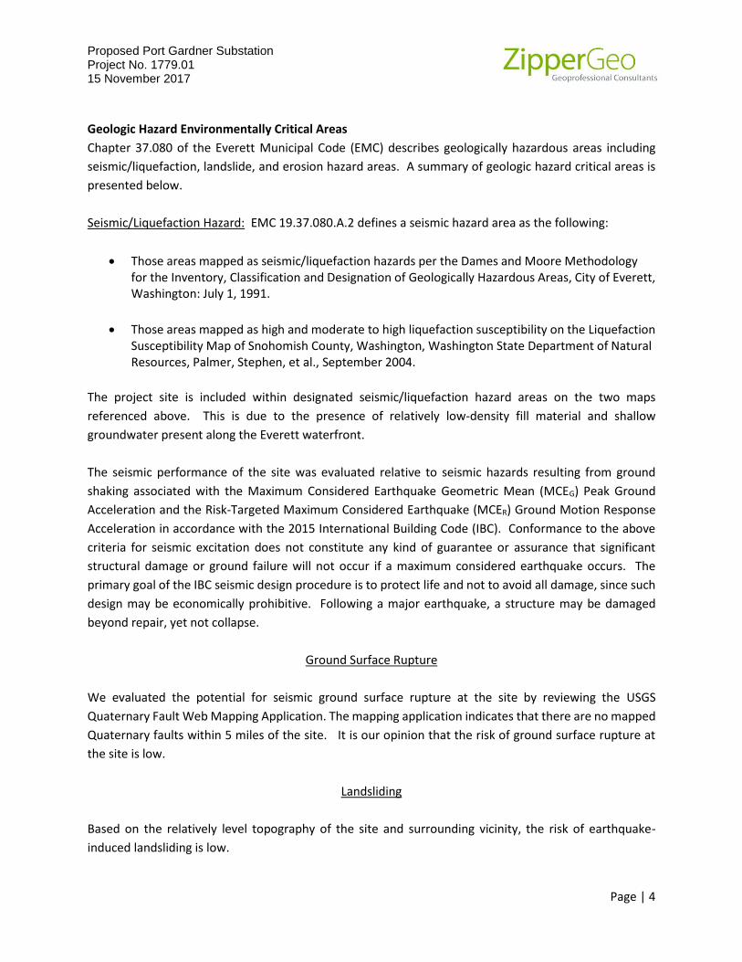
Geologic Hazard Environmentally Critical Areas
Chapter 37.080 of the Everett Municipal Code (EMC) describes geologically hazardous areas including
seismic/liquefaction, landslide, and erosion hazard areas. A summary of geologic hazard critical areas is
presented below.
Seismic/Liquefaction Hazard: EMC 19.37.080.A.2 defines a seismic hazard area as the following:
• Those areas mapped as seismic/liquefaction hazards per the Dames and Moore Methodology for the Inventory, Classification and Designation of Geologically Hazardous Areas, City of Everett, Washington: July 1, 1991.
• Those areas mapped as high and moderate to high liquefaction susceptibility on the Liquefaction Susceptibility Map of Snohomish County, Washington, Washington State Department of Natural Resources, Palmer, Stephen, et al., September 2004.
The project site is included within designated seismic/liquefaction hazard areas on the two maps
referenced above. This is due to the presence of relatively low-density fill material and shallow
groundwater present along the Everett waterfront.
The seismic performance of the site was evaluated relative to seismic hazards resulting from ground
shaking associated with the Maximum Considered Earthquake Geometric Mean (MCEG) Peak Ground
Acceleration and the Risk-Targeted Maximum Considered Earthquake (MCER) Ground Motion Response
Acceleration in accordance with the 2015 International Building Code (IBC). Conformance to the above
criteria for seismic excitation does not constitute any kind of guarantee or assurance that significant
structural damage or ground failure will not occur if a maximum considered earthquake occurs. The
primary goal of the IBC seismic design procedure is to protect life and not to avoid all damage, since such
design may be economically prohibitive. Following a major earthquake, a structure may be damaged
beyond repair, yet not collapse.
Ground Surface Rupture
We evaluated the potential for seismic ground surface rupture at the site by reviewing the USGS
Quaternary Fault Web Mapping Application. The mapping application indicates that there are no mapped
Quaternary faults within 5 miles of the site. It is our opinion that the risk of ground surface rupture at
the site is low.
Landsliding
Based on the relatively level topography of the site and surrounding vicinity, the risk of earthquake-
induced landsliding is low.

Proposed Port Gardner Substation Project No. 1779.01 15 November 2017
Page | 5
Soil Liquefaction
Liquefaction is a phenomenon wherein saturated cohesionless soils build up excess pore water pressures
during earthquake loading. Liquefaction typically occurs in loose soils, but may occur in denser soils if the
ground shaking is sufficiently strong. ZGA completed a liquefaction analysis in general accordance with
Section 1803.5.12 of the 2015 IBC and Section 11.8.3 of ASCE 7-10. Specifically, our analysis used the
following primary seismic ground motion parameters.
• A Maximum Considered Earthquake Geometric Mean (MCEG) Peak Ground Acceleration of
0.530g, based on Figure 22-7 of ASCE 7-10.
• A Modified Peak Ground Acceleration (PGAM) of 0.477g based on Site Class E, per Section 11.8.3
of ASCR7-10 (Site Class modification to MCEG without regard to liquefaction in accordance with
Sections 11.4.7 and 20.3.1 of ASCE 7-10).
• A Geometric Mean Magnitude of 6.73 based on 2008 USGS National Seismic Hazard Mapping
Project deaggregation data for a seismic event with a 2% probability of exceedance in 50 years
(2,475-year return period).
Our liquefaction analysis was completed using the computer program LiquefyPro Version 5.8. Our analysis
was based on boring B-1 completed to a depth of 54 feet and site-specific laboratory tests. The
approximate exploration location is shown on the enclosed Site and Exploration Plan, Figure 1. Our
analysis indicates the potential for liquefaction from the groundwater table (about 3 ½ feet below grade)
to a depth of about 31½ feet. Appendix C contains the liquefaction analysis output graphic.
Liquefaction Settlement
Based on our analyses, we estimate a total seismic settlement of approximately 6 to 8 inches. Potentially
liquefiable soils are located a few feet below the ground surface. As such, soil liquefaction may be
expressed at the ground surface as sand boils, ground cracks, and vertical settlements. Given the shallow
nature of potentially liquefiable soils, we estimate a differential seismic settlement range of 4½ o 6 inches
over a horizontal distance of 50 feet.
Erosion Hazard: The project site lacks significant slopes and is mantled by fill material. The site does not
meet the criteria for an erosion hazard area as described in EMC 19.37.080.A.3.
Landslide Hazard: The project site and immediate vicinity lack significant slopes. The nearest slope of
significant height (about 80 feet) is located approximately 150 feet to the east and is comprised of Vashon
glacial till, advance outwash, and older glacially consolidated soils. Consequently, the risk of landsliding
impacting the site is low and the site does not meet the criteria for a landslide hazard as described in EMC
19.37.080.A.1, in our opinion.

Proposed Port Gardner Substation Project No. 1779.01 15 November 2017
Page | 6
Earthwork
The following sections present recommendations for site preparation, subgrade preparation and
placement of engineered fills on the project. The recommendations presented in this report for design
and construction of foundations and slabs are contingent upon following the recommendations outlined
in this section.
Earthwork on the project should be observed and evaluated by a ZGA representative. Evaluation of
earthwork should include observation and testing of structural fill, subgrade preparation, foundation
bearing soils, deep foundations, and subsurface drainage installations.
Site Preparation
Environmental Considerations: The environmental site exploration and analytical laboratory testing
disclosed some minor occurrences of regulated environmental contaminants. These are discussed in
detail in the Environmental Site Assessment report which is presented under separate cover. The
presence of limited regulated environmental contaminants is not expected to preclude use of on-site soils
as structural fill (as conduit or utility trench backfill, for example). Specific recommendations regarding
handling and disposition of the excavation spoils are presented in the Environmental Site Assessment
report.
Demolition: Activities completed prior to the installation of new foundations and site elements should
begin with the removal of all existing asphalt pavement. We also recommend removal of the existing
underground utilities. Excavations associated with utility removal should be backfilled with structural fill
placed and compacted in accordance with the recommendations presented in the Structural Fill section
of this report.
Site Preparation
It should be recognized that the site is characterized by a relatively shallow groundwater condition and
that the soil below the existing pavement consists of loose grading to very loose sand with a variable silt
content. Given the uncontrolled nature of previous filling at the site, subgrade conditions may vary from
the soils observed at the exploration locations. We recommend compacting the subgrade to a firm and
non-yielding condition. Areas where loose or soft soils exist should be compacted to a minimum
compaction level of 95 percent of the modified Proctor maximum dry density as determined by the ASTM
D 1557 test procedure if possible, but we anticipate that this may not be feasible across the site,
particularly if grading takes place during wet weather. If the material cannot be adequately compacted,
it should either be moisture conditioned, or removed to a depth no greater than 1 foot and the material
replaced with crushed surfacing base course compacted to a relatively firm and non-yielding condition.
Adequate subgrade compaction can only be achieved when the soils are within approximately 2 percent
of the optimum moisture content, and the existing soil moisture content should be expected to increase
with depth.

Proposed Port Gardner Substation Project No. 1779.01 15 November 2017
Page | 7
Structural Fill Placement and Compaction
All fill material placed on site should be placed in accordance with the recommendations herein for
structural fill. Prior to placement, the surfaces to receive structural fill should be prepared as previously
described. All structural fill should be free of organic material, debris, or other deleterious material.
Individual particle size should generally be less than 2 inches in maximum dimension.
The suitability of soils for use as structural fill depends primarily on the gradation and moisture content
of the soil when it is placed. As the amount of fines (that soil fraction passing the US No. 200 sieve)
increases, soil becomes increasingly sensitive to small changes in moisture content and adequate
compaction becomes more difficult, or impossible, to achieve. Generally, soils containing more than
about 5 percent fines by weight (based on that soil fraction passing the US No. 4 sieve) cannot be
compacted to a firm, non-yielding condition when the moisture content is more than a few percent from
optimum. The optimum moisture content is that which yields the greatest soil density under a given
compactive effort.
Use of On-site Soils: The site soils below the pavement section likely to be encountered in excavations
consist of fine sand with some silt and trace gravel. The feasibility of using these soils to backfill utility
excavations and around below-grade structures (such as catch basins and vaults) and adjacent to
foundations will depend on the soil’s moisture content at the time of placement. Groundwater is
expected to be quite shallow during most times of the year, and soils excavated from below the water
table will need to be dried to within 2 percent of the optimum moisture content in order to compact them
to the recommended density. Re-use of on-site soils should be undertaken in accordance with the
project’s soil management plan relative to regulated environmental contaminants.
We anticipate that on-site soils will be used to backfill conduit trenches above the bedding, around below-
grade vaults, and in storm system trenches. From a gradation standpoint, it would be feasible to use these
soils as structural fill borrow provided that the soil moisture content at the time of placement allows
compaction to between 90 and 95 percent of the modified Proctor maximum dry density (ASTM D 1557)
per Table 2, presented subsequently. Some wood was observed in the fill, and depending on the amount
observed during construction, it may need to be removed prior to using site soils as fill.
Imported Structural Fill: We recommend that imported soils for use as general structural fill material
consist of a well-graded sand and gravel with a low fines content, such as the District’s standard substation
fill, the gradation of which is presented in the table below.

Proposed Port Gardner Substation Project No. 1779.01 15 November 2017
Page | 8
Table 1: Snohomish County PUD No. 1 Substation Import Granular Fill Gradation
US Standard Sieve Size Percent Passing by Dry Weight Basis
2 inch 100
½ inch 56 - 100
¼ inch 40 - 78
No. 10 22 - 57
No. 40 8 - 32
No. 200 < 5
Alternatively, we recommend importing material meeting the criteria in WSDOT Specification 9-03.9(3)
Crushed Surfacing (base course gradation). The fill should be compacted to between 90 and 95 percent
of the modified Proctor maximum dry density per Table 2.
The use of other fill types should be reviewed and approved by the District and ZGA prior to their use on
site. Structural fill should be placed and compacted in horizontal lifts, using equipment and procedures
that will produce the recommended moisture content and densities throughout the fill. Fill lifts should
generally not exceed 10 inches in loose thickness, although the nature of the compaction equipment in
use and its effectiveness will influence functional fill lift thicknesses.
Compaction Recommendations: Structural fill should be placed in horizontal lifts and compacted to a firm
and non-yielding condition. Recommended compaction criteria for structural fill materials, including
trench backfill, are as follows:
Table 2: Recommended Soil Compaction Levels
Location Minimum Percent Compaction*
All fill below slabs and foundations supported by piling 90
General fill embankments 95
Utility and conduit trench backfill 95
Landscape Areas 90
* ASTM D 1557 Modified Proctor Maximum Dry Density
Earthwork may be difficult or impossible during periods of elevated soil moisture and wet weather. If
soils are stockpiled for future use and wet weather is anticipated, the stockpile should be protected with
securely anchored plastic sheeting.
Subgrade soils that become disturbed due to elevated moisture conditions should be overexcavated to a
limited extent as discussed previously as excavating deeper at this site will not expose denser or drier
soils. We recommend that the earthwork portion of this project be completed during extended periods
of dry weather if possible. If earthwork is completed during the wet season (typically November through
June) it will be necessary to take extra precautionary measures to protect subgrade soils. Wet season
earthwork may require additional mitigative measures beyond that which would be expected during the
Proposed Port Gardner Substation Project No. 1779.01 15 November 2017
Page | 9
drier summer and fall months. This could include diversion of surface runoff around exposed soils and
draining of ponded water. Once subgrades are established, it will be necessary to protect the exposed
subgrade soils from construction traffic during wet weather if non-select fill is used. Placing quarry spalls,
crushed recycled concrete, clean pit-run sand and gravel, or the salvaged yard rock over these areas would
further protect the soils from construction traffic.
If earthwork takes place during freezing conditions, we recommend allowing the exposed subgrade to
thaw and then recompacting the subgrade prior to placing subsequent lifts of engineered fill. Frozen soil
should not be used as structural fill.
A ZGA representative should be present during the construction phase of the project to observe
earthwork operations and to perform necessary tests and observations during subgrade preparation,
placement and compaction of structural fill, backfilling of excavations, and prior to construction of
foundations and slabs.
Drainage: Positive drainage should be provided during construction and maintained throughout the life
of the project. Uncontrolled movement of water into trenches or foundation and slab excavations during
construction should be prevented.
Additional Considerations: It is anticipated that excavations for the proposed substation improvements
can be accomplished with conventional earthmoving equipment.
Excavation Quantities: It has been our experience that grading calculations need to accommodate a
“shrink or swell” factor when comparing in-place soil volumes to truck volumes. We recommend
considering that the in-place volume of soil removed from excavations will increase by approximately 25
to 40 percent when measured on a loose cubic yards basis (truck yards). Likewise, loose truck yards
delivered to the site will shrink on the order of 25 to 30 percent when compared to the in-place compacted
volume of the soil. Truck yards are also subject to other discrepancies when correlating to bank yards,
including “rounding errors” that can be significant.
Utility Installation Recommendations
Below-grade utilities will include conduits and storm sewer piping and structures. We recommend that
utility trenching conform to all applicable federal, state, and local regulations, such as OSHA and WISHA,
for open excavations. We anticipate that the existing very loose to loose fill material will generally be
adequate for support of utilities, but some foundation improvement is recommended for grade-sensitive
piping. We recommend tamping a minimum of 6 inches of coarse crushed rock, such as material meeting
the requirements for Permeable Ballast as described in Specification 9-03.9(2) of the 2010 WSDOT
Standard Specifications, into the trench bottom prior to placing bedding for conduit or other utilities.
All trenches should be wide enough to allow for compaction around the haunches of the pipe. If water is
encountered in the excavations, it should be removed prior to placing pipe or conduit and subsequent fill

Proposed Port Gardner Substation Project No. 1779.01 15 November 2017
Page | 10
placement. Materials, placement and compaction of utility trench backfill exclusive of CDF should be in
accordance with the recommendations presented in the Structural Fill section of this report. In our
opinion, the initial lift thickness should not exceed one foot unless recommended by the manufacturer to
protect utilities from damage by compacting equipment. Light, hand operated compaction equipment
may be utilized directly above utilities if damage resulting from heavier compaction equipment is of
concern.
Dewatering: Depending upon the time of year that the work takes place, the depth of the utilities, and
possibly tidal conditions, groundwater seepage should be expected in excavations. Seepage could be
heavy enough to require temporary dewatering measures and flattening the sidewalls of excavations to
reduce the risk of caving. The contractor should be prepared to pump water from excavations into either
the storm or sanitary sewer or an on-site sump. Dewatering water discharged from the site will need to
comply with permit requirements issued by the City of Everett. We recommend that dewatering
effectively lower the water table at least 2 feet below the bottoms of excavations until they are backfilled.
Temporary Excavation Slopes: We recommend that utility trenching, installation, and backfilling conform
to all applicable Federal, State, and local regulations such as WISHA and OSHA regulations for open
excavations. In order to maintain the function of any existing utilities that may be located near
excavations, we recommend that temporary excavations not encroach upon the bearing splay of existing
utilities, foundations, or slabs. The bearing splay of structures and utilities not supported on piles should
be considered to begin at the edge of the utility, foundation, or slab and extend downward at a 1H:1V
(Horizontal:Vertical) slope. If, due to space constraints, an open excavation cannot be completed without
encroaching on a utility, we recommend shoring the new utility excavation with a slip box or other suitable
means that provide for protection of workers and that maintain excavation sidewall integrity to the depth
of the excavation.
Temporary slope stability is a function of many factors, including the following:
• The presence and abundance of groundwater;
• The type and density of the various soil strata;
• The depth of cut;
• Surcharge loadings adjacent to the excavation;
• The length of time the excavation remains open.
It is exceedingly difficult under the variable circumstances presented by uncontrolled fill material to pre-
establish a safe and “maintenance-free” temporary cut slope angle. Therefore, it should be the
responsibility of the contractor to maintain safe slope configurations since the contractor is continuously

Proposed Port Gardner Substation Project No. 1779.01 15 November 2017
Page | 11
at the job site, able to observe the nature and condition of the cut slopes, and able to monitor the
subsurface materials and groundwater conditions encountered. It may be necessary to drape temporary
slopes with plastic or to otherwise protect the slopes from the elements and minimize sloughing and
erosion. We do not recommend vertical slopes or cuts deeper than 4 feet if worker access is necessary.
The cuts should be adequately sloped or supported to prevent injury to personnel from local sloughing
and spalling. The excavation should conform to applicable Federal, State, and local regulations.
Based upon our review of WAC 296-155-66401 (Appendix A – Soil Classification), we have interpreted the
existing fill disclosed by the explorations to meet the Type C definition. The contractor should be
responsible for determining soil types in all excavations and should be prepared to adequately shore or
slope all excavations. It should be noted that the site soil observed at the exploration locations is granular
and may be subject to rapid collapse in unsupported conditions.
Below-grade Vault Recommendations
Bearing Conditions: Below-grade conduit vaults will be installed as part of the project. Based upon our
experience with other District substations, and depending on the orientation of the new conduit sweeps,
the vault bases may be up to approximately 8 feet below grade, although due to the site’s shallow
groundwater conditions, shallower vaults may be considered. Based upon conditions disclosed by the
explorations, we anticipate that vault subgrades will consist of very loose granular fill material.
The vaults will exert a relatively low bearing pressure on the existing fill soils, and we estimate that up to
approximately 1 inch of settlement may take place soon after the vaults are installed. Some subgrade
improvement is recommended to reduce the potential for differential settlement. Placing a minimum 6-
inch compacted thickness of crushed rock below the vaults will reduce the potential for differential
settlement. The crushed rock should conform to the quality and gradation requirements for Crushed
Surfacing – Base Course of the WSDOT Standard Specifications [Specification 9-03.9(3)]. Moderate to
rapid groundwater seepage should be expected for excavations that extend into groundwater. The
contractor should be prepared to dewater excavations to the extent necessary to allow for installation of
vaults, conduits, and bedding and backfill materials in accordance with the District’s requirements.
Buoyancy Considerations: The vaults will be subject to buoyant forces if they are water-tight. Potential
buoyant forces acting on the vaults may be calculated by multiplying the volume of the portion of the
vault below the water table (in cubic feet) by 62.4 pcf. Buoyant forces may be resisted by the weight of a
vault and its contents. Additional resistance to buoyant forces may be achieved by installing flanges on
the vault base. The weight of the soil backfill placed above the flanges will assist in counteracting buoyant
forces. We recommend using a soil density of 125 pcf for backfill above the water table, and 60 pcf for
backfill below the water table.
Seismic Design Parameters
Per the 2015 IBC seismic design procedures and ASCE 7-10, the presence of liquefiable soils requires a Site
Class definition of F. However, through reference to Sections 11.4.7 and 20.3.1 of ASCE 7-10, the IBC
allows site coefficients Fa and Fv to be determined assuming that liquefaction does not occur for structures
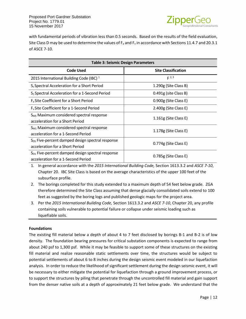
Proposed Port Gardner Substation Project No. 1779.01 15 November 2017
Page | 12
with fundamental periods of vibration less than 0.5 seconds. Based on the results of the field evaluation,
Site Class D may be used to determine the values of Fa and Fv in accordance with Sections 11.4.7 and 20.3.1
of ASCE 7-10.
Table 3: Seismic Design Parameters
Code Used Site Classification
2015 International Building Code (IBC) 1 F 2, 3
Ss Spectral Acceleration for a Short Period 1.290g (Site Class B)
S1 Spectral Acceleration for a 1-Second Period 0.491g (site Class B)
Fa Site Coefficient for a Short Period 0.900g (Site Class E)
Fv Site Coefficient for a 1-Second Period 2.400g (Site Class E)
SMS Maximum considered spectral response
acceleration for a Short Period 1.161g (Site Class E)
SM1 Maximum considered spectral response
acceleration for a 1-Second Period 1.178g (Site Class E)
SDS Five-percent damped design spectral response
acceleration for a Short Period 0.774g (Site Class E)
SD1 Five-percent damped design spectral response
acceleration for a 1-Second Period 0.785g (Site Class E)
1. In general accordance with the 2015 International Building Code, Section 1613.3.2 and ASCE 7-10,
Chapter 20. IBC Site Class is based on the average characteristics of the upper 100 feet of the
subsurface profile.
2. The borings completed for this study extended to a maximum depth of 54 feet below grade. ZGA
therefore determined the Site Class assuming that dense glacially consolidated soils extend to 100
feet as suggested by the boring logs and published geologic maps for the project area.
3. Per the 2015 International Building Code, Section 1613.3.2 and ASCE 7-10, Chapter 20, any profile
containing soils vulnerable to potential failure or collapse under seismic loading such as
liquefiable soils.
Foundations
The existing fill material below a depth of about 4 to 7 feet disclosed by borings B-1 and B-2 is of low
density. The foundation bearing pressures for critical substation components is expected to range from
about 240 psf to 1,300 psf. While it may be feasible to support some of these structures on the existing
fill material and realize reasonable static settlements over time, the structures would be subject to
potential settlements of about 6 to 8 inches during the design seismic event modeled in our liquefaction
analysis. In order to reduce the likelihood of significant settlement during the design seismic event, it will
be necessary to either mitigate the potential for liquefaction through a ground improvement process, or
to support the structures by piling that penetrate through the uncontrolled fill material and gain support
from the denser native soils at a depth of approximately 21 feet below grade. We understand that the
Proposed Port Gardner Substation Project No. 1779.01 15 November 2017
Page | 13
District has decided to support the more settlement-sensitive structures on augercast piles, and our
recommendations for augercast piles are summarized following the Shallow Foundation section below.
Shallow Foundation Design Recommendations
Some of the substation structures may be supported by conventional shallow foundations provided that
the District is willing to accept the potential for significant settlement in association with the IBC-defined
seismic event. In the event that the District is willing to consider shallow foundation support for some of
the substation elements, such as the circuit switcher, 12.5 kw switch support, or neutral reactor, the
recommendations presented below would be applicable. Please note that our recommendations are
based upon subsurface conditions disclosed at the locations of borings B-1 and B-2 and the environmental
probes, and that shallow foundation subgrade conditions at the locations of the structures may warrant
subgrade preparation conditions that vary from those described herein in the event that conditions
different from those considered in our recommendations at the time of construction vary.
It will be feasible to use conventional shallow foundations for new structures bearing upon the existing
medium dense fill material provided that the District can accommodate the anticipated settlement not
related to that associated with the design seismic event. Recommended criteria for shallow foundations
are summarized below.
Net allowable bearing pressure: 1,300 psf. This value incorporates a factor of safety of 3. A one-third
increase may be applied for short-term wind or seismic loading.
Minimum base dimension: 4 feet
Minimum embedment for frost protection: 18 inches
Approximate total settlement: 1 inch
Estimate differential settlement: One half of total settlement
Ultimate passive resistance: 400 psf. This value assumes that foundations are backfilled with granular
backfill compacted to 95 percent density and does not include a factor of safety. Neglect the upper 18
inches of embedment when calculating passive resistance.
Ultimate coefficient of base friction: 0.4
Shallow Foundation Construction Considerations
The base of all foundation excavations should be free of water, loose soil, or debris prior to placing
concrete, and should be compacted as recommended in this report. Concrete should be placed soon after
excavating and compaction to reduce bearing soil disturbance. Should the soils at bearing level become
excessively dry, disturbed, saturated, or frozen, the affected soil should be removed prior to placing
concrete. A lean concrete mud-mat or a 12-inch thick lift of compacted crushed rock should be placed
Proposed Port Gardner Substation Project No. 1779.01 15 November 2017
Page | 14
over the bearing soils if the excavations must remain open for an extended period of time. We
recommend that a ZGA representative observe foundation subgrade conditions prior to form and
reinforcing steel placement.
We recommend that shallow foundations for the substation elements be underlain by a minimum 12-inch
compacted thickness of crushed rock meeting the requirements for Crushed Surfacing Base Course as
described in WSDOT Specification 9-03.9(3) compacted to at least 95 percent of the material's modified
Proctor maximum dry density (ASTM D 1557). Alternatively, the excavation may be backfilled with lean
mix concrete or CDF with a minimum compressive strength of 55 psi. In this case, the overexcavation
need only be as wide as the foundation. The layer of compacted crushed surfacing base course should
extend outward from the shallow foundations’ lower edges by 1 foot.
Augercast Pile Foundation Recommendations
The very loose to loose fill material extending to approximately 21 feet below the substation is not
adequate for support of the substation components given the calculated settlement associated with the
design seismic event. Therefore, we recommend that a deep foundation system bearing within the denser
native soil underlying the fill material be utilized to provide support for the structures. While a variety of
deep foundation systems are available, based upon our experience with similar projects and soil
conditions, as well as the District’s preference, we recommend that consideration be given to using
augercast piles.
Based upon our experience with the previous District substation projects with similar site conditions, we
understand preliminary pile foundation loads may be as follows:
• Dead end towers: 2 kips;
• Circuit Switcher: 8.1 kips;
• Transformer: 245 kips;
• 12kv Switch: 1.8 kips;
• Neutral Reactor: 1 kip;
• Switch gear enclosure: 50 kips.
The sections below provide our recommendations for augercast pile resistances and construction
considerations.
Pile Resistance: This section presents ultimate axial resistances for 18-inch diameter augercast piles. The
resistances presented below were determined in general accordance with the methods presented in
Proposed Port Gardner Substation Project No. 1779.01 15 November 2017
Page | 15
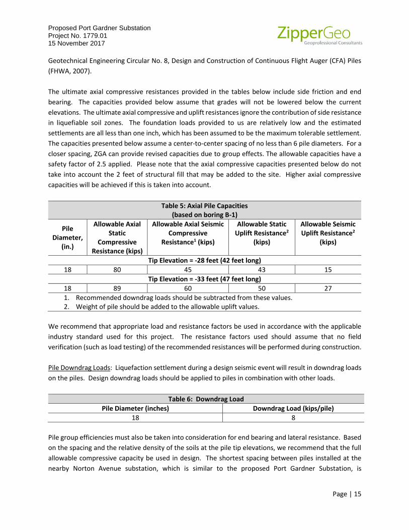
Geotechnical Engineering Circular No. 8, Design and Construction of Continuous Flight Auger (CFA) Piles
(FHWA, 2007).
The ultimate axial compressive resistances provided in the tables below include side friction and end
bearing. The capacities provided below assume that grades will not be lowered below the current
elevations. The ultimate axial compressive and uplift resistances ignore the contribution of side resistance
in liquefiable soil zones. The foundation loads provided to us are relatively low and the estimated
settlements are all less than one inch, which has been assumed to be the maximum tolerable settlement.
The capacities presented below assume a center-to-center spacing of no less than 6 pile diameters. For a
closer spacing, ZGA can provide revised capacities due to group effects. The allowable capacities have a
safety factor of 2.5 applied. Please note that the axial compressive capacities presented below do not
take into account the 2 feet of structural fill that may be added to the site. Higher axial compressive
capacities will be achieved if this is taken into account.
Table 5: Axial Pile Capacities (based on boring B-1)
Pile Diameter,
(in.)
Allowable Axial Static
Compressive Resistance (kips)
Allowable Axial Seismic Compressive
Resistance1 (kips)
Allowable Static Uplift Resistance2
(kips)
Allowable Seismic Uplift Resistance2
(kips)
Tip Elevation = -28 feet (42 feet long)
18 80 45 43 15
Tip Elevation = -33 feet (47 feet long)
18 89 60 50 27
1. Recommended downdrag loads should be subtracted from these values. 2. Weight of pile should be added to the allowable uplift values.
We recommend that appropriate load and resistance factors be used in accordance with the applicable
industry standard used for this project. The resistance factors used should assume that no field
verification (such as load testing) of the recommended resistances will be performed during construction.
Pile Downdrag Loads: Liquefaction settlement during a design seismic event will result in downdrag loads
on the piles. Design downdrag loads should be applied to piles in combination with other loads.
Table 6: Downdrag Load
Pile Diameter (inches) Downdrag Load (kips/pile)
18 8
Pile group efficiencies must also be taken into consideration for end bearing and lateral resistance. Based
on the spacing and the relative density of the soils at the pile tip elevations, we recommend that the full
allowable compressive capacity be used in design. The shortest spacing between piles installed at the
nearby Norton Avenue substation, which is similar to the proposed Port Gardner Substation, is

Proposed Port Gardner Substation Project No. 1779.01 15 November 2017
Page | 16
approximately 6.4 feet between piles that are in line with each other. Based on this spacing, we
recommend that 80 percent of the lateral capacity of a single pile be used for design.
Lateral Resistance: Lateral loads can be resisted by a combination passive pressure soil resistance acting
on embedded portions of the pile caps and lateral resistance of the piles. Recommendations for passive
resistance are provided in the Shallow Foundations section of this report. Recommended geotechnical
input parameters for use in lateral pile analysis programs are provided in the table below. ZGA can
provided pile deflection estimates once structural design criteria have been developed.
Table 7: Soil Parameters for LPILE Analysis
Elevation
(ft)
Effective
Unit
Weight
’
(pcf)
Friction Angle,
(degrees)
Cohesion,
C
(psf)
Modulus of Horizontal
Subgrade Reaction, k
(pci)* 50
(%)
p-y
Soil Model
Static Seismic Static Seismic
14 to 10 105 33 33 0 25 25 0
Sand above
groundwater
table
10 to -7 40 31 4 0 20 2 0
Sand below
groundwater
table
-7 to -21 60 36 36 0 60 60 0
Sand below
groundwater
table
-21 to -34 65 38 38 0 125 125 0
Sand below
groundwater
table
-34 to
-38.5 70 39 39 0 125 125 0
Sand below
groundwater
table
-38.5 to
-40 80 42 42 0 125 125 0
Sand below
groundwater
table
* Values for the Seismic Condition include the effects of liquefaction.
Augercast Pile Construction Considerations: Augercast piles should be installed to the recommended pile
tip elevations using a continuous-flight, hollow-stem auger. As is common practice, the pile grout would
be pumped under pressure through the hollow stem as the auger is withdrawn.
We recommend that the augercast piles be installed by a contractor experienced in their placement and
using suitable equipment. Grout pumps must be fitted with a volume-measuring device and a pressure
gauge so that the volume of grout placed in each pile and the pressure head can be easily determined.

Proposed Port Gardner Substation Project No. 1779.01 15 November 2017
Page | 17
While grouting, the rate of auger withdrawal must be controlled such that the volume of grout pumped
is equivalent to at least 115 to 120 percent of the theoretical drilled hole volume. However, larger grout
volumes may occur because the grout may tend to flow out into loose soil zones. A minimum grout line
pressure of 100 psi must be maintained while grouting. Also, a minimum head of grout of 8 feet should
be maintained above the auger tip at all times as the auger is being retracted from the hole. We
recommend that there be a waiting period of at least 24 hours between installation of piles spaced closer
than about 10 feet center-to-center in order to avoid disturbance of concrete undergoing curing in a
previously cast pile.
Although no apparent obstructions were encountered within the recommended pile depths while
advancing borings B-1 and B-2 and the environmental probes, obstructions such as buried debris, rip-rap,
logs and stumps, general waste material, piling or wharf materials, and rubble may be encountered during
pile installation due to the presence of fill to a depth of approximately 21 feet. The use of pre-excavation
or other techniques may be required to remove obstructions and the contractor should be prepared to
use these or other similar procedures where necessary. If pile refusal occurs above the recommended
pile tip elevation, the pile should be relocated in accordance with the recommendations of the project
structural engineer.
It should be noted that the recommended pile tip elevations and capacities presented above are based
on assumed uniformity of soil conditions across the site. There may be unexpected variations in the depth
to and characteristics of the supporting soils. In addition, no direct information regarding the capacity of
augercast piles (e.g., driving resistance data) is obtained while this type of pile is being installed.
Therefore, it is particularly important that the installation of augercast piles be completed under the direct
observation of an experienced geotechnical engineer. Accordingly, we recommend that pile installation
be monitored by a member of our staff who will observe installation procedures and evaluate the
adequacy of individual pile installations. Additionally, we recommend construction specifications similar
to those recommended in Geotechnical Engineering Circular No. 8, Design and Construction of Continuous
Flight Auger Piles (FHWA 2007) be used for the project.
Augercast pile construction at the project site will create saturated spoils and excess grout that will tend
to flow. An appropriate plan should be developed to contain and remove the spoils and grout. The spoils
should be handled in accordance with an approved Soil Management Plan.
Driveway Flexible Pavement Section Recommendations
The substation driveway will be paved with asphalt and is expected to generally accommodate light to
moderate service vehicle loading although occasional heavier loads will be present during future
maintenance and construction activity. The District has indicated that the pavement should be able to
accommodate H20 loading.
Pavement Life and Maintenance: It should be realized that asphaltic pavements are not maintenance-
free. The following pavement sections represent our minimum recommendations for an average level of
performance during a 20-year design life; therefore, an average level of maintenance will likely be

Proposed Port Gardner Substation Project No. 1779.01 15 November 2017
Page | 18
required. Thicker asphalt, base, and subbase courses would offer better long-term performance, but
would cost more initially. Conversely, thinner courses would be more susceptible to “alligator” cracking
and other failure modes. As such, pavement design can be considered a compromise between a high
initial cost and low maintenance costs versus a low initial cost and higher maintenance costs.
Soil Design Values: Pavement subgrade soils are anticipated to consist of imported gravelly sand with a
low fines content above loose granular fill soils. Our analysis assumes the pavement section subgrade will
have a minimum California Bearing Ratio (CBR) value of 5.
Recommended Pavement Section: We recommend 4 inches of asphalt concrete over 6 inches (compacted
thickness) of crushed surfacing top course above 8 inches (compacted thickness) of crushed surfacing base
course. Alternatively, 4 inches of Asphalt Treated Base (ATB) may be used instead of the 6 inches of top
course.
We recommend the following regarding asphalt pavement materials and pavement construction.
Subgrade Preparation and Compaction: The upper 12 inches of the pavement section subgrade should
be prepared in accordance with the recommendations presented in the Subgrade Preparation section of
this report, and all fill should be compacted in accordance with the recommendations presented in the
Structural Fill section of this report.
Asphalt Concrete: We recommend that the asphalt concrete conform to Section 9-02.1(4) for PG 58-22
or PG 64-22 Performance Graded Asphalt Binder as presented in the 2012 WSDOT Standard Specifications.
We also recommend that the gradation of the asphalt aggregate conform to the aggregate gradation
control points for ½-inch mixes as presented in Section 9-03.8(6), HMA Proportions of Materials.
Base Course and Top Course: We recommend that the crushed surfacing conform to Section 9-03.9(3) of
the WSDOT Standard Specifications.
Compaction and Paving: All base material should be compacted to at least 95 percent of the maximum
dry density determined in accordance with ASTM D 1557. We recommend that asphalt be compacted to
a minimum of 92 percent of the Rice (theoretical maximum) density. Placement and compaction of
asphalt should conform to requirements of Section 5-04 of the WSDOT Standard Specifications.
We recommend that the District consider using ATB instead of crushed surfacing base course in the event
that construction takes place during wet weather and if construction equipment will be traversing the
driveway prior to placing the wearing course of asphalt. ATB will provide an all-weather surface which
would reduce the need for driveway maintenance during construction and yield less turbid runoff during
rainy weather. Areas of ATB that are degraded under construction traffic loading could then be repaired
prior to final paving with the asphalt wearing course.

Proposed Port Gardner Substation Project No. 1779.01 15 November 2017
Page | 19
Preliminary Stormwater Management Considerations
It is our understanding that the design will need to comply with criteria described in the Washington State
Department of Ecology 2014 Stormwater Management Manual for Western Washington, the manual
adopted by the City of Everett. Stormwater management plans were still being developed at the time this
report was prepared. However, we understand that the project may rely upon storage provided by the
fill embankment constructed as part of site improvements, and that that infiltration will likely be
considered as well. Preliminary considerations related to stormwater management are summarized
below. Additional exploration, lab testing, and analysis are recommended as part of the final stormwater
management design.
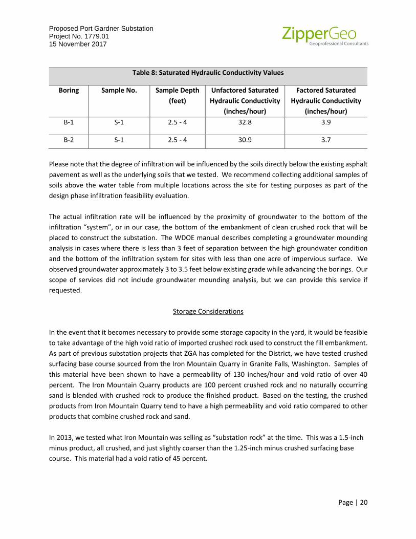
Saturated Hydraulic Conductivity
The current WDOE manual used by the City of Everett allows a determination of saturated hydraulic
conductivity using the following formula:
Log10 (Ksat, initial) = -1.57 + 1.9D10 + 0.015D60 – 0.013D90 -2.08ffines where:
D10 = grain size diameter (mm) for which 10 percent of the sample by weight is finer
D60 = grain size diameter (mm) for which 60 percent of the sample by weight is finer
D90 = grain size diameter (mm) for which 90 percent of the sample by weight is finer
ffines = fraction of the sample by weight that passes the US No. 200 sieve.
Correction factors identified in the WDOE manual must be applied to the values derived using this formula
when developing a design saturated hydraulic conductivity value. We recommend applying the following
correction factors, as described in Table 3.3.1 Correction Factors to the Used with In-Situ Saturated
Hydraulic Conductivity Measurements to Estimate Design Rates of the Manual.
• Site variability and number of locations tested: CFv = 0.33
• Testing methodology correction: CFt = 0.4
• Degree of influent control to prevent siltation and bio-buildup: CFm = 0.9
Using the grain size data and the formula described in the current WDOE manual, we derived the values
presented in the table below that incorporate correction factors for the testing methodology, site
variability, and effluent control. The values are based on mechanical grain size analysis of two soil samples
collected at depths of 2.5 to 4 feet.
Proposed Port Gardner Substation Project No. 1779.01 15 November 2017
Page | 20
Table 8: Saturated Hydraulic Conductivity Values
Boring Sample No. Sample Depth
(feet)
Unfactored Saturated
Hydraulic Conductivity
(inches/hour)
Factored Saturated
Hydraulic Conductivity
(inches/hour)
B-1 S-1 2.5 - 4 32.8 3.9
B-2 S-1 2.5 - 4 30.9 3.7
Please note that the degree of infiltration will be influenced by the soils directly below the existing asphalt
pavement as well as the underlying soils that we tested. We recommend collecting additional samples of
soils above the water table from multiple locations across the site for testing purposes as part of the
design phase infiltration feasibility evaluation.
The actual infiltration rate will be influenced by the proximity of groundwater to the bottom of the
infiltration “system”, or in our case, the bottom of the embankment of clean crushed rock that will be
placed to construct the substation. The WDOE manual describes completing a groundwater mounding
analysis in cases where there is less than 3 feet of separation between the high groundwater condition
and the bottom of the infiltration system for sites with less than one acre of impervious surface. We
observed groundwater approximately 3 to 3.5 feet below existing grade while advancing the borings. Our
scope of services did not include groundwater mounding analysis, but we can provide this service if
requested.
Storage Considerations
In the event that it becomes necessary to provide some storage capacity in the yard, it would be feasible
to take advantage of the high void ratio of imported crushed rock used to construct the fill embankment.
As part of previous substation projects that ZGA has completed for the District, we have tested crushed
surfacing base course sourced from the Iron Mountain Quarry in Granite Falls, Washington. Samples of
this material have been shown to have a permeability of 130 inches/hour and void ratio of over 40
percent. The Iron Mountain Quarry products are 100 percent crushed rock and no naturally occurring
sand is blended with crushed rock to produce the finished product. Based on the testing, the crushed
products from Iron Mountain Quarry tend to have a high permeability and void ratio compared to other
products that combine crushed rock and sand.
In 2013, we tested what Iron Mountain was selling as “substation rock” at the time. This was a 1.5-inch
minus product, all crushed, and just slightly coarser than the 1.25-inch minus crushed surfacing base
course. This material had a void ratio of 45 percent.

Proposed Port Gardner Substation Project No. 1779.01 15 November 2017
Page | 21
Clean imported aggregate will also have a relatively high saturated hydraulic conductivity. As part of the
design phase of the East Arlington substation project that we completed for the District in 2016, we
collected a sample of processed material meeting the gradation specification for Crushed Surfacing – Base
Course Gradation as described in WSDOT 9-03.9(3) from Cal Portland of Everett, Washington and
completed a permeability test in order to determine its usefulness in terms of providing benefits for
stormwater management. The sample was compacted to approximately 95 percent of the modified
Proctor maximum dry density in order to replicate its condition at the substation and tested for
permeability in general accordance with the ASTM D 2434 methodology. The sample was found to have
saturated hydraulic conductivity of 2.2 X 10⁻² cm/sec (30.8 inches/hour).
Although we did not determine the void ratio of the sample of Cal Portland crushed surfacing that we
previously tested, we expect that it will have a lower value than the Iron Mountain product. Specifying
the use of crushed surfacing base course that is 100 percent crushed and not a blended product would be
advantageous given currently available local aggregate products.
Storage within a crushed rock fill embankment may be achieved by constructing berms of low
permeability soil that allow collecting captured water and discharging it to an appropriate location.
Additional Considerations
We understand that the substation yard grade will be about 2 feet above existing site grade. This may
present a situation where water infiltrating into the fill embankment may seep out the sides onto lower
adjacent ground (including the sidewalk along West Marine View Drive). We anticipate that it would be
prudent to include an interceptor drain along the sides of the embankment bordering lower ground such
that water can be collected and directed to an appropriate discharge.
The property to the south and southwest of the substation site is about 2 feet higher. It would be
beneficial to install a curb or low wall along the south and southwest sides of the substation to reduce the
likelihood of surface water from the adjacent property flowing onto the substation site.
Erosion Control
Construction phase erosion control activities are recommended to include measures intended to reduce
erosion and subsequent sediment transport. Although the site is flat and small, we recommend that the
project incorporate the following erosion and sedimentation control measures during construction:
• Capturing water from low permeability surfaces and directing it away from bare soil exposures.
• Erosion control BMP inspection and maintenance: The contractor should be aware that
inspection and maintenance of erosion control BMPs is critical toward their satisfactory
performance. Repair and/or replacement of dysfunctional erosion control elements should be
anticipated.

Proposed Port Gardner Substation Project No. 1779.01 15 November 2017
Page | 22
• Undertake site preparation, excavation, and filling during periods of little or no rainfall.
• Cover soil stockpiles with anchored plastic sheeting.
• Provide an all-weather quarry spall construction site entrance.
• Provide street cleaning on an as-needed basis.
• Protect exposed soil surfaces that will be subject to vehicle traffic with crushed rock, crushed
recycled concrete, or pit run sand and gravel to reduce the likelihood of subgrade disturbance
and sediment generation during wet weather or wet site conditions.
• Install perimeter siltation control fencing, anchored straw or coir wattles along the site
perimeter.
CLOSURE
The analysis and recommendations presented in this report are based, in part, on the explorations
completed for this study. The number, location, and depth of the explorations were completed within
the constraints of budget and site access so as to yield the information to formulate our
recommendations. Project plans were in the preliminary stage at the time this report was prepared. We
therefore recommend we be provided an opportunity to review the final plans and specifications when
they become available in order to assess that the recommendations and design considerations presented
in this report have been properly interpreted and implemented into the project design.
The performance of earthwork, structural fill, foundations, and pavements depend greatly on proper site
preparation and construction procedures. We recommend that Zipper Geo Associates, LLC be retained
to provide geotechnical engineering services during the earthwork-related construction phases of the
project. If variations in subsurface conditions are observed at that time, a qualified geotechnical engineer
could provide additional geotechnical recommendations to the contractor and design team in a timely
manner as the project construction progresses.

B-2
B-1
GP-3
GP-4
GP-5
GP-1
GP-2
GP-6
A
'
A
REFERENCE: CONCEPTUAL SITE PLAN PROVIDED BY SNOHOMISH PUD, SEPT. 9, 2016
FIGUREJob No.
Zipper Geo Associates, LLC
19023 36th Ave. W.,Suite D
Lynnwood, WA
SHT. of 11
SITE AND EXPLORATION PLAN
1779.01NOVEMBER 2017
1
PORT GARDNER SUBSTATION1210 Marine View Drive
Everett, Washington
SCALE IN FEET
020 2010
LEGEND
B-1 BORING NUMBER AND
APPROXIMATE LOCATION
GP-1 GEOPROBE NUMBER AND
APPROXIMATE LOCATION

A'A
0
5
10
-5
-10
-15
-20
-25
-30
-35
-40
-45
-50
-55
0
5
10
-5
-10
-15
-20
-25
-30
-35
-40
-45
-50
-55
GP-3
B-2 B-1
GP-1
ELE
VA
TIO
N IN
F
EE
T
ELE
VA
TIO
N IN
F
EE
T
Brown SAND with trace gravel.
(ADVANCE OUTWASH)
(Offset 19 ft. to the ESE) (Offset 23 ft. to the WNW)
7
Very loose to loose, gray to brown,
silty SAND with some wood and
shell fragments. (FILL)
Gray, silty SAND with
gravel, some wood and
shell fragments. (FILL)
Medium dense, brown, fine to
medium SAND with trace wood
fibers. (ADVANCE OUTWASH)
Dense to very dense, brown, fine to
medium SAND trace gravel and silt
laminae. (ADVANCE OUTWASH)
Hard, gray, SILT and clayey
silt with fine sand laminae and
trace fine organics.
(PRE-FRASER DEPOSITS)
4
1
0
1
0
7
29
23
50
39
49
46
GROUND SURFACE ELEVATION = APPROXIMATELY 14 FEET
Very loose to loose, gray to brown,
silty SAND with some wood and
shell fragments. (FILL)
Medium dense, gray to brown,
fine to medium SAND with trace
silt, gravel, and wood fibers.
(ADVANCE OUTWASH)
Dense, brown, fine to medium
SAND some fine gravel.
(ADVANCE OUTWASH)
Hard, gray, SILT with fine sand laminae
and very dense, gray, silty fine SAND.
(PRE FRASER DEPOSITS)
7
3
4
1
4
1
4
18
20
29
39
31
43
60
Gray, fine SAND
with trace silt and
SILT with fine sand,
some wood and
shell fragments.
(FILL)
Very dense, brown,
SAND with trace
gravel. (ADVANCE
OUTWASH)
?
?
?
?
ATD
ATDATD
ATD
15
15
FIGUREJob No.
Zipper Geo Associates, LLC
19023 36th Ave. W.,Suite D
Lynnwood, WA
SHT. of11
GENERALIZED CROSS SECTION, A-A'
1779.01NOVEMBER 2017
2
PORT GARDNER SUBSTATION1210 Marine View Drive
Everett, Washington
SCALE IN FEET
010 105
REFERENCE:(1) CONCEPTUAL SITE PLAN, DRAWING S-119-P2, PREPARED BY SNOHOMISH CO. PUD, DATED SEPTEMBER 9, 2016. (2) ZGA BORING LOGS
BORING EXPLANATION
5
6
B-1
7
BORING NUMBER
SPT BLOWCOUNT
BOTTOM OF BORING
6
INFERRED SOIL CONTACT
ATD
GROUNDWATER AT TIME OF DRILLING
GEOPROBE BORING NUMBER AND OFFSET FROM CROSS SECTION
BOTTOM OF BORING
INFERRED SOIL CONTACT
ATD
GROUNDWATER AT TIME OF DRILLING
GP-3
(Offset 19 ft. to the ESE)

APPENDIX A
FIELD EXPLORATION PROCEDURES AND LOGS
FIELD EXPLORATION PROCEDURES AND LOGS
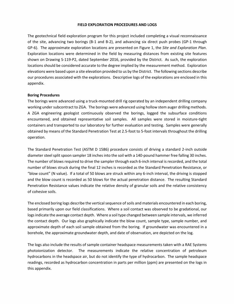
The geotechnical field exploration program for this project included completing a visual reconnaissance
of the site, advancing two borings (B-1 and B-2), and advancing six direct push probes (GP-1 through
GP-6). The approximate exploration locations are presented on Figure 1, the Site and Exploration Plan.
Exploration locations were determined in the field by measuring distances from existing site features
shown on Drawing S-119-P2, dated September 2016, provided by the District. As such, the exploration
locations should be considered accurate to the degree implied by the measurement method. Exploration
elevations were based upon a site elevation provided to us by the District. The following sections describe
our procedures associated with the explorations. Descriptive logs of the explorations are enclosed in this
appendix.
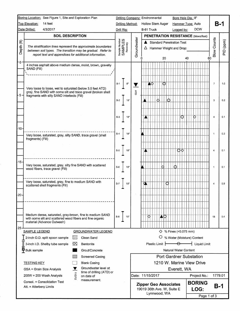
Boring Procedures
The borings were advanced using a truck-mounted drill rig operated by an independent drilling company
working under subcontract to ZGA. The borings were advanced using hollow stem auger drilling methods.
A ZGA engineering geologist continuously observed the borings, logged the subsurface conditions
encountered, and obtained representative soil samples. All samples were stored in moisture-tight
containers and transported to our laboratory for further evaluation and testing. Samples were generally
obtained by means of the Standard Penetration Test at 2.5-foot to 5-foot intervals throughout the drilling
operation.
The Standard Penetration Test (ASTM D 1586) procedure consists of driving a standard 2-inch outside
diameter steel split spoon sampler 18 inches into the soil with a 140-pound hammer free falling 30 inches.
The number of blows required to drive the sampler through each 6-inch interval is recorded, and the total
number of blows struck during the final 12 inches is recorded as the Standard Penetration Resistance, or
“blow count” (N value). If a total of 50 blows are struck within any 6-inch interval, the driving is stopped
and the blow count is recorded as 50 blows for the actual penetration distance. The resulting Standard
Penetration Resistance values indicate the relative density of granular soils and the relative consistency
of cohesive soils.
The enclosed boring logs describe the vertical sequence of soils and materials encountered in each boring,
based primarily upon our field classifications. Where a soil contact was observed to be gradational, our
logs indicate the average contact depth. Where a soil type changed between sample intervals, we inferred
the contact depth. Our logs also graphically indicate the blow count, sample type, sample number, and
approximate depth of each soil sample obtained from the boring. If groundwater was encountered in a
borehole, the approximate groundwater depth, and date of observation, are depicted on the log.
The logs also include the results of sample container headspace measurements taken with a RAE Systems
photoionization detector. The measurements indicate the relative concentration of petroleum
hydrocarbons in the headspace air, but do not identify the type of hydrocarbon. The sample headspace
readings, recorded as hydrocarbon concentration in parts per million (ppm) are presented on the logs in
this appendix.

Direct Push Explorations
The environmental explorations were advanced with a rig employing a direct-push sampler equipped with
disposable PVC sample sleeves. Throughout the drilling operation, soil samples were obtained from 4-
foot long pushes driven into the ground using a percussion hammer. The steel sampling tube was
extracted from the hole and the liners were removed and split open. An effort was made to sample soil
continuously from the ground surface to the total depth of each exploration, but sample recovery varied
in each exploration. Samples were initially visually classified in the field and then subsequently in our
laboratory.


GEOPROBE BORING LOGProject Number : 1779.01Boring Number : GP-1
Project Name : Port Gardner Substation Ground Surface Elevation : NALocation : North, middle of parking lot Depth to Water : 3.15 ftDriller / Crew : Standard Environmental Probe Start / Finish Date : 4/05/17
Depth (ft.)
Monitoring Well Completion
Sample ID / Recovery (in.)
Laboratory Samples PID (ppm) Sheen Description
Depth (ft.)
Approximately 3-inches of asphalt.None
ND
GP1-15 5
NoneND
None
10 ND 10
None
0.215 15
GP1-2
ND
20 20Sampler Type Static Water Level Logged by: EICContinuous Core Water Level (ATD) Approved by: JME
Gray, silty fine SAND, some wood fragments, saturated, moderate odor (not hydrocarbon).
At 19 1/2 ft, gray, gravelly fine to medium SAND, medium dense, moist, moderate odor (not hydrocarbon).
Sheet 1 of 2Zipper Geo Associates, LLC
Gray, fine to medium SAND with shell fragments, moist. (Fill)
Gray, fine SAND with trace silt, some wood fragments, grading to gray, silty SAND, and grading to gray, fine SAND, saturated. (Fill)
S1/36
S2/42
S3/42
S4/42
S5/42
Gray, fine SAND with trace silt, some wood fragments, saturated, no odor.
Gray, SILT with fine sand, grading to silty fine SAND, saturated, moderate odor (not hydrocarbon).

GEOPROBE BORING LOGProject Number : 1779.01Boring Number : GP-1
Project Name : Port Gardner Substation Ground Surface Elevation : NALocation : North, middle of parking lot Depth to Water : 3.15 ftDriller / Crew : Standard Environmental Probe Start / Finish Date : 4/05/17
Depth (ft.)
Monitoring Well Completion
Sample ID / Recovery (in.)
Laboratory Samples PID (ppm) Sheen Description
Depth (ft.)
20 None
GP1-3 NDBoring terminated at 22 ft due to heaving.
25 25
30 30
35 35
40 40Sampler Type Static Water Level Logged by: EICContinuous Core Water Level (ATD) Approved by: JME
Sheet 2 of 2Zipper Geo Associates, LLC
S6/24
Brown, fine to medium SAND with trace gravel at 21 ft, medium dense, moist, no odor. (Native)
GEOPROBE BORING LOGProject Number : 1779.01Boring Number : GP-2
Project Name : Port Gardner Substation Ground Surface Elevation : NALocation : East side of parking lot Depth to Water : 3.5 ftDriller / Crew : Standard Enviromental Probe Start / Finish Date : 4/05/17
Depth (ft.)
Monitoring Well Completion
Sample ID / Recovery (in.)
Laboratory Samples PID (ppm) Sheen Description
Depth (ft.)
Approximately 3-inches of asphalt.None
ND
GP2-1 1-inch lense of gray, silty SAND.
None5 5
ND
None
10 ND 10
None
GP2-2 0.415 15
None
ND
GP2-3 None
20 20Sampler Type Static Water Level Logged by: EICContinuous Core Water Level (ATD) Approved by: JME
Gray, fine SAND with trace silt, saturated, moderate odor (none hydrocarbon). At 19 1/2 ft, 4-inch lense of gravel.
At 19.9 ft, gray, gravelly fine to medium SAND, medium dense, moist, moderate odor (not hydrocarbon).
Sheet 1 of 2Zipper Geo Associates, LLC
S1/30
S2/30
S3/42
S4/36
S5/36
Brown, fine to medium SAND with shell fragments, moist, moderate odor (not hydrocarbon). (Fill)
Gray, fine SAND, grading to gray, silty SAND, some wood fragments, saturated, moderate odor (not hydrocarbon). (Fill)
Gray, fine SAND with trace silt, some wood fragments, saturated, moderate odor (not hydrocarbon). (Fill)
Gray, SILT with fine sand, some wood fragments, wet, moderate odor (not hydrocarbon). (Fill)
GEOPROBE BORING LOGProject Number : 1779.01Boring Number : GP-2
Project Name : Port Gardner Substation Ground Surface Elevation : NALocation : East side of parking lot Depth to Water : 3.5 ftDriller / Crew : Standard Environmental Probe Start / Finish Date : 4/5/17
Depth (ft.)
Monitoring Well Completion
Sample ID / Recovery (in.)
Laboratory Samples PID (ppm) Sheen Description
Depth (ft.)
20 None
Boring terminated at 22 ft due to heaving.
25 25
30 30
35 35
40 40Sampler Type Static Water Level Logged by: EICContinuous Core Water Level (ATD) Approved by: JME
Sheet 2 of 2Zipper Geo Associates, LLC
S6/24
Brown, fine to medium SAND with trace gravel, grading to fine to medium SAND, saturated, no odor. (Native)

GEOPROBE BORING LOGProject Number : 1779.01Boring Number : GP-3
Project Name : Port Gardner Substation Ground Surface Elevation : NALocation : SE of parking lot near boat yard fence Depth to Water : 3.0 ftDriller / Crew : Standard Environmental Probe Start / Finish Date : 4/05/17
Depth (ft.)
Monitoring Well Completion
Sample ID / Recovery (in.)
Laboratory Samples PID (ppm) Sheen Description
Depth (ft.)
Approximately 3-inches of asphalt.None
ND
GP3-1None
5 5
ND
GP3-2
None
10 ND 10
None
ND
15 15
0.5 None
20 4-inch gravel layer with wood fragments. 20Sampler Type Static Water Level Logged by: EICContinuous Core Water Level (ATD) Approved by: JME
Sheet 1 of 2
S5/24
Brown, gravelly SAND with shell fragments, moist, moderate odor (not hydrocarbon). (Fill)
Gray, silty SAND, some with wood fragments, saturated, moderate odor (not hydrocarbon). (FILL)
Zipper Geo Associates, LLC
S1/42
S2/42
S3/42
S4/24
Gray, gravelly SAND with some silt, saturated, moderate odor (not hydrocarbon). (Fill)
Gray, fine SAND with trace silt grading to gray, silty SAND, some shell fragments, moist to wet, moderate odor (not hydrocarbon). (Fill)
At 11 1/2 ft, gray, SILT with fine sand, wet, moderate odor (not hydrocarbon).
Gray, SILT with fine sand grading to gray, silty fine SAND, some wood fragments, saturated to wet, moderate odor (not hydrocarbon). (Fill)
GEOPROBE BORING LOGProject Number : 1779.01Boring Number : GP-3
Project Name : Port Gardner Substation Ground Surface Elevation : NALocation : SE of parking lot near boat yard fence Depth to Water : 3.0 ftDriller / Crew : Standard Environmental Probe Start / Finish Date : 4/5/17
Depth (ft.)
Monitoring Well Completion
Sample ID / Recovery (in.)
Laboratory Samples PID (ppm) Sheen Description
Depth (ft.)
20 None
ND
GP3-3Boring terminated at 24 ft due to heaving.
25 25
30 30
35 35
40 40Sampler Type Static Water Level Logged by: EICContinuous Core Water Level (ATD) Approved by: JME
Sheet 2 of 2Zipper Geo Associates, LLC
S6/48
Brown, fine to medium SAND with trace gravel, moist, no odor. (Native)

GEOPROBE BORING LOGProject Number : 1779.01Boring Number : GP-4
Project Name : Port Gardner Substation Ground Surface Elevation : NALocation : SW of parking lot near boat yard Depth to Water : 3.5 ftDriller / Crew : Standard Environmental Probe Start / Finish Date : 4/05/17
Depth (ft.)
Monitoring Well Completion
Sample ID / Recovery (in.)
Laboratory Samples PID (ppm) Sheen Description
Depth (ft.)
Approximately 3-inches of asphalt.None
GP4-1 0.9None
5 5
ND
Some wood fragments.
NoneGP4-2
10 ND 10
None
ND
15 15
No recovery.
20 20Sampler Type Static Water Level Logged by: EICContinuous Core Water Level (ATD) Approved by: JME
S5/0
Gray, fine to medium SAND, moist, strong odor (not hydrocarbon). (Fill)
Gray, fine SAND with trace silt, moist, moderate odor (not hydrocarbon). (Fill)
Gray, fine SAND with trace silt grading to gray silty SAND, some wood fragments, saturated, moderate odor (not hydrocarbon). (Fill)
Gray, silty SAND, some wood fragments, saturated, no odor. (Fill)
At 15 ft, gray, SILT with some fine sand, wood fragments, moist, moderate odor (not hydrocarbon). (Fill)
S4/18
Sheet 1 of 2Zipper Geo Associates, LLC
S1/42
S2/42
S3/48
GEOPROBE BORING LOGProject Number : 1779.01Boring Number : GP-4
Project Name : Port Gardner Substation Ground Surface Elevation : NALocation : SW of parking lot near boat yard fence Depth to Water : 3.50 ftDriller / Crew : Standard Environmental Probe Start / Finish Date : 4/05/17
Depth (ft.)
Monitoring Well Completion
Sample ID / Recovery (in.)
Laboratory Samples PID (ppm) Sheen Description
Depth (ft.)
20 None
ND
GP4-3Boring terminated at 23 ft due to heaving.
25 25
30 30
35 35
40 40Sampler Type Static Water Level Logged by: EICContinuous Core Water Level (ATD) Approved by: JME
Sheet 2 of 2Zipper Geo Associates, LLC
S6/36
Brown, fine to medium SAND with some gravel, moist, no odor.

GEOPROBE BORING LOGProject Number : 1779.01Boring Number : GP-5
Project Name : Port Gardner Substation Ground Surface Elevation : NALocation : West side of parking lot Depth to Water : 3 ftDriller / Crew : Standard Environmental Probe Start / Finish Date : 4/05/17
Depth (ft.)
Monitoring Well Completion
Sample ID / Recovery (in.)
Laboratory Samples PID (ppm) Sheen Description
Depth (ft.)
Approximately 3-inches of asphalt.None
GP5-1 0.9None
5 5
ND
GP5-2None
10 ND 10
None
ND
15 GP5-3 15
NDNone
20 Boring terminated at 20 ft due to heaving. 20Sampler Type Static Water Level Logged by: EICContinuous Core Water Level (ATD) Approved by: JME
S3/24
S4/42
S5/42
Gray, medium SAND with shall fragments, some wood fragments, moist, moderate odor (potentially hydrocarbon). (Fill)
Gray, silty fine SAND, some wood fragments, moist. (Fill)
Gray, silty fine SAND, some wood fragments, saturated. (Fill)
Gray, silty fine SAND grading to black, silty fine SAND, some wood fragments, saturated. (Fill)
Gray, medium SAND with some silt, trace gravel and wood fragments, wet, moderate odor (potentially hydrocarbon). (Fill)
Gray, fine to medium SAND with some gravel, saturated.
Brown, gravelly SAND, saturated to moist, no odor. (Native)
Sheet 1 of 1Zipper Geo Associates, LLC
Gray, fine to medium SAND, some wood fragments, moist, moderate odor (potentially hydrocarbon). (Fill)
S1/30
S2/42

GEOPROBE BORING LOGProject Number : 1779.01Boring Number : GP-6
Project Name : Port Gardner Substation Ground Surface Elevation : NALocation : North of parking lot near gate entrance Depth to Water : 3.5 ftDriller / Crew : Standard Environmental Probe Start / Finish Date : 4/05/17
Depth (ft.)
Monitoring Well Completion
Sample ID / Recovery (in.)
Laboratory Samples PID (ppm) Sheen Description
Depth (ft.)
Approximately 3-inches of asphalt.None
0.9
None5 GP6-1 5
ND
GP6-2None
10 ND 10
GP6-3No recovery.
15 15
None
ND
20 Boring terminated at 20 ft due to heaving. 20Sampler Type Static Water Level Logged by: EICContinuous Core Water Level (ATD) Approved by: JME
Brown, fine to medium SAND containing pyrite with gravel, saturated, no odor. (Native)
Sheet 1 of 1Zipper Geo Associates, LLC
S1/30
S2/48
S3/24
S4/0
S5/36
Gray, fine to medium SAND with gravel, moist, strong odor (not hydrocarbon). (Fill)
At 3 1/2 ft, wood layer with strong odor (not hydrocarbon).
Gray, fine to medium SAND, trace shell and wood fragments, moist, strong to moderate odor (not hydrocarbon). (Fill)
Gray, silty fine SAND, moist, moderate odor (not hydrocarbon). (Fill)

APPENDIX B
GEOTECHNICAL LABORATORY TESTING PROCEDURES AND RESULTS
GEOTECHNICAL LABORATORY TESTING PROCEDURES AND RESULTS
A series of laboratory tests were performed during the course of this study to evaluate the index and
geotechnical engineering properties of the subsurface soils. Descriptions of the types of tests performed
are given below.
Visual Classification
Samples recovered from the exploration locations were visually classified in the field during the
exploration program. Representative portions of the samples were carefully packaged in moisture tight
containers and transported to our laboratory where the field classifications were verified or modified as
required. Visual classification was generally done in accordance with ASTM D 2488. Visual soil
classification includes evaluation of color, relative moisture content, soil type based upon grain size, and
accessory soil types included in the sample. Soil classifications are presented on the exploration logs in
Appendix A.
Moisture Content Determinations
Moisture content determinations were performed on representative samples obtained from the
explorations in order to aid in identification and correlation of soil types. The determinations were made
in general accordance with the test procedures described in ASTM D 2216. The results are shown on the
exploration logs in Appendix A.
Grain Size Analysis
A grain size analysis indicates the range in diameter of soil particles included in a particular sample. Grain
size analyses were performed on representative samples in general accordance with ASTM D 422. The
results of the grain size determinations for the samples were used in classification of the soils, and are
presented in this appendix.
Fines Content Determination
The fines content (soil fraction finer than the US No. 200 sieve) of selected samples was completed in
general accordance with the procedures described in ASTM C117. Test results are presented on the logs
in Appendix A.

0
10
20
30
40
50
60
70
80
90
100
0.0010.0100.1001.00010.000100.0001000.000
PE
RC
EN
T F
INE
R B
Y W
EIG
HT
PARTICLE SIZE IN MILLIMETERS
GRAIN SIZE ANALYSIS
Comments:
36" 12" 6" 3" 1 1/2" 3/4" 3/8" 4 10 20 40 60 140 200
Coarse Medium Fine Silt ClayFineCoarse
COBBLESBOULDERS GRAVEL SAND FINE GRAINED
SIZE OF OPENING IN INCHES U.S. STANDARD SIEVE SIZE HYDROMETER
Project No.: PROJECT NAME:
Port Gardner SubstationDATE OF TESTING:
Exploration Sample Depth (feet) Moisture (%) Fines (%) Description
B-1 2.5 - 4 ft. 20.3SAND, some silt, trace gravel
S-1 9.4
1779.01
4/5/2017
ASTM D 422Test Results Summary
Zipper Geo Associates, LLCGeotechnical and Environmental Consultants

0
10
20
30
40
50
60
70
80
90
100
0.0010.0100.1001.00010.000100.0001000.000
PE
RC
EN
T F
INE
R B
Y W
EIG
HT
PARTICLE SIZE IN MILLIMETERS
GRAIN SIZE ANALYSIS
Comments:
36" 12" 6" 3" 1 1/2" 3/4" 3/8" 4 10 20 40 60 140 200
Coarse Medium Fine Silt ClayFineCoarse
COBBLESBOULDERS GRAVEL SAND FINE GRAINED
SIZE OF OPENING IN INCHES U.S. STANDARD SIEVE SIZE HYDROMETER
Project No.: PROJECT NAME:
Port Gardner SubstationDATE OF TESTING:
Exploration Sample Depth (feet) Moisture (%) Fines (%) Description
B-1 5 - 6.5 ft. 24.1SAND with silt, trace gravel
S-2 14.6
1779.01
4/5/2017
ASTM D 422Test Results Summary
Zipper Geo Associates, LLCGeotechnical and Environmental Consultants

0
10
20
30
40
50
60
70
80
90
100
0.0010.0100.1001.00010.000100.0001000.000
PE
RC
EN
T F
INE
R B
Y W
EIG
HT
PARTICLE SIZE IN MILLIMETERS
GRAIN SIZE ANALYSIS
Comments:
36" 12" 6" 3" 1 1/2" 3/4" 3/8" 4 10 20 40 60 140 200
Coarse Medium Fine Silt ClayFineCoarse
COBBLESBOULDERS GRAVEL SAND FINE GRAINED
SIZE OF OPENING IN INCHES U.S. STANDARD SIEVE SIZE HYDROMETER
Project No.: PROJECT NAME:
Port Gardner SubstationDATE OF TESTING:
Exploration Sample Depth (feet) Moisture (%) Fines (%) Description
B-1 12.5 - 14 ft. 33.4Silty SAND, trace gravel
S-5 36.2
1779.01
4/5/2017
ASTM D 422Test Results Summary
Zipper Geo Associates, LLCGeotechnical and Environmental Consultants

0
10
20
30
40
50
60
70
80
90
100
0.0010.0100.1001.00010.000100.0001000.000
PE
RC
EN
T F
INE
R B
Y W
EIG
HT
PARTICLE SIZE IN MILLIMETERS
GRAIN SIZE ANALYSIS
Comments:
36" 12" 6" 3" 1 1/2" 3/4" 3/8" 4 10 20 40 60 140 200
Coarse Medium Fine Silt ClayFineCoarse
COBBLESBOULDERS GRAVEL SAND FINE GRAINED
SIZE OF OPENING IN INCHES U.S. STANDARD SIEVE SIZE HYDROMETER
Project No.: PROJECT NAME:
Port Gardner SubstationDATE OF TESTING:
Exploration Sample Depth (feet) Moisture (%) Fines (%) Description
B-1 27.5 - 29 ft. 21.7SAND, some silt, trace gravel
S-9 9.9
1779.01
4/5/2017
ASTM D 422Test Results Summary
Zipper Geo Associates, LLCGeotechnical and Environmental Consultants
0
10
20
30
40
50
60
70
80
90
100
0.0010.0100.1001.00010.000100.0001000.000
PE
RC
EN
T F
INE
R B
Y W
EIG
HT
PARTICLE SIZE IN MILLIMETERS
GRAIN SIZE ANALYSIS
Comments:
36" 12" 6" 3" 1 1/2" 3/4" 3/8" 4 10 20 40 60 140 200
Coarse Medium Fine Silt ClayFineCoarse
COBBLESBOULDERS GRAVEL SAND FINE GRAINED
SIZE OF OPENING IN INCHES U.S. STANDARD SIEVE SIZE HYDROMETER
Project No.: PROJECT NAME:
Port Gardner SubstationDATE OF TESTING:
Exploration Sample Depth (feet) Moisture (%) Fines (%) Description
B-1 32.5 ft. 24.2SAND, trace silt and gravel
S-10 4.7
1779.01
4/5/2017
ASTM D 422Test Results Summary
Zipper Geo Associates, LLCGeotechnical and Environmental Consultants

0
10
20
30
40
50
60
70
80
90
100
0.0010.0100.1001.00010.000100.0001000.000
PE
RC
EN
T F
INE
R B
Y W
EIG
HT
PARTICLE SIZE IN MILLIMETERS
GRAIN SIZE ANALYSIS
Comments:
36" 12" 6" 3" 1 1/2" 3/4" 3/8" 4 10 20 40 60 140 200
Coarse Medium Fine Silt ClayFineCoarse
COBBLESBOULDERS GRAVEL SAND FINE GRAINED
SIZE OF OPENING IN INCHES U.S. STANDARD SIEVE SIZE HYDROMETER
Project No.: PROJECT NAME:
Port Gardner SubstationDATE OF TESTING:
Exploration Sample Depth (feet) Moisture (%) Fines (%) Description
B-2 2.5 - 4 ft. 24.7SAND, some silt, trace gravel
S-1 10.7
1779.01
4/5/2017
ASTM D 422Test Results Summary
Zipper Geo Associates, LLCGeotechnical and Environmental Consultants

APPENDIX C
LIQUEFACTION ANALYSIS OUTPUT PLOT