Geotechnical Assessment of a Dam Site: A Case Study of ... 6_2_5.pdf · Geotechnical Assessment of...
16
Journal of Earth Sciences and Geotechnical Engineering, vol. 6, no.2, 2016, 73-88 ISSN: 1792-9040 (print), 1792-9660 (online) Scienpress Ltd, 2016 Geotechnical Assessment of a Dam Site: A Case Study of Nkari Dam, South Eastern Nigeria U. N. Umoren 1 , A. E. Edet 1 and A. S. Ekwere 1 Abstract Geotechnical as well as geophysical investigation methods were used to provide information for the assessment of the subsurface lithology along the proposed Nkari Dam Axis in South Eastern Nigeria. This paper reports on the geotechnical methods applied in the studies. Field tests; Dutch Cone Penetrometer (CPT), Standard Penetration Test (SPT), natural moisture content determination and borehole drilling for groundwater observation and lithologic identification were carried out. Disturbed and undisturbed soil samples were obtained from test pits and boreholes for different laboratory tests. Natural moisture content, specific gravity, bulk densities, Atterberg Limits, Consolidation settlement, Triaxial and Direct Shear tests, Unconfined Compression tests etc were determined. Assessment of data indicated deep-seated clay as dam foundation and potential watertight reservoir. The drilling records indicated maximum penetration depth of 5.0-6.9m. The subsurface consists of two main layers of clayey-silt to clayey shales. The top layer made of clayey-silt is about 2.3m thick while the underlying shale unit extends to a depth of 20m and beyond. This consolidated shales underlying the overburden, constitute the penetration refusals in the SPT boring process. A two-layer earth model fits the proposed dam site with the top layer having thickness less than 6m at the high grounds and averaging 2m in the valleys. The geological study prior to and during the present study has not indicated any faulting in the dam axis. Keywords: CPT, Lithology, Overburden, Bearing Capacity, Sandstone, Semi- consolidated. 1 Introduction A Dam is an engineering structure constructed on a river or stream to divert, or store water for the purpose of water supply, energy generation, irrigation, flood control, ground water recharge, conservation storage and recreation among others. Weirs and Barrages are similar to dams but weirs, otherwise called low-head dam is small overflow-type dam 1 Department of Geology, University of Calabar, Calabar, Nigeria.
Transcript of Geotechnical Assessment of a Dam Site: A Case Study of ... 6_2_5.pdf · Geotechnical Assessment of...
Journal of Earth Sciences and Geotechnical Engineering, vol. 6, no.2, 2016, 73-88 ISSN: 1792-9040 (print), 1792-9660 (online) Scienpress Ltd, 2016
Geotechnical Assessment of a Dam Site: A Case Study of
Nkari Dam, South Eastern Nigeria
U. N. Umoren1, A. E. Edet1 and A. S. Ekwere1
Abstract Geotechnical as well as geophysical investigation methods were used to provide information for the assessment of the subsurface lithology along the proposed Nkari Dam Axis in South Eastern Nigeria. This paper reports on the geotechnical methods applied in the studies. Field tests; Dutch Cone Penetrometer (CPT), Standard Penetration Test (SPT), natural moisture content determination and borehole drilling for groundwater observation and lithologic identification were carried out. Disturbed and undisturbed soil samples were obtained from test pits and boreholes for different laboratory tests. Natural moisture content, specific gravity, bulk densities, Atterberg Limits, Consolidation settlement, Triaxial and Direct Shear tests, Unconfined Compression tests etc were determined. Assessment of data indicated deep-seated clay as dam foundation and potential watertight reservoir. The drilling records indicated maximum penetration depth of 5.0-6.9m. The subsurface consists of two main layers of clayey-silt to clayey shales. The top layer made of clayey-silt is about 2.3m thick while the underlying shale unit extends to a depth of 20m and beyond. This consolidated shales underlying the overburden, constitute the penetration refusals in the SPT boring process. A two-layer earth model fits the proposed dam site with the top layer having thickness less than 6m at the high grounds and averaging 2m in the valleys. The geological study prior to and during the present study has not indicated any faulting in the dam axis.
Keywords: CPT, Lithology, Overburden, Bearing Capacity, Sandstone, Semi-consolidated.
1 Introduction A Dam is an engineering structure constructed on a river or stream to divert, or store water for the purpose of water supply, energy generation, irrigation, flood control, ground water recharge, conservation storage and recreation among others. Weirs and Barrages are similar to dams but weirs, otherwise called low-head dam is small overflow-type dam
1Department of Geology, University of Calabar, Calabar, Nigeria.
74 U. N. Umoren et al.
commonly used to raise the level of a river or stream, divert the water or control the flow whereas a barrage is a construction across a water course to increase the depth of water to assist navigation or irrigation (Bruce & Melboume 1997) A site characterization programme is a plan of action for obtaining estimates of parameters to be used in modeling engineering performance. In other words, site characterization is the enterprise of exploring and investigating a site to gain sufficient information about the geometry and material properties of local geological formations which rational engineering decisions can be made.(Rowe 2001) The general characteristics of a dam site are revealed in the geotechnical, hydrological and environmental studies of the site. However, the design and construction of a dam to ensure its structural adequacy (foundation safety and slope stability) considers mostly the geotechnical and hydrological studies. This research emphasizes the geotechnical characterization of Nkari Dam site. The Cross River Basin Development Authority intends to construct this dam for the purpose of storing water for irrigation, water supply ,power generation and fisheries. The proposed Nkari Dam is located in the South Eastern part of Nigeria. The Dam is intended to impound runoff contributed by Ehie and Idim Ibom river tributaries with other rivulets to the Enyong Creek Flood Plains. The dam’s estimated capacity will about 3.34x10⁶ m3 with a total height of 13m (including free board) and crest length of 1300m. The geotechnical characterization of the proposed dam is based on desk, field and laboratory geotechnical studies.
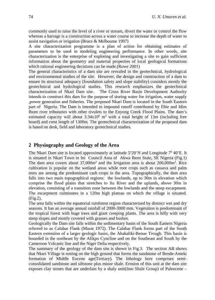
2 Physiography and Geology of the Area The Nkari Dam site is located approximately at latitude 5o20’N and Longitude 70 40’E. It is situated in Nkari Town in Ini Council Area of Akwa Ibom State, SE Nigeria (Fig.1) The dam area covers about 37,000m2 and the Irrigation area is about 200,000m2. Rice cultivation is popular on the wetland areas while root crops such as cassava and palm trees are among the predominant cash crops in the area. Topographically, the dam area falls into two main topographical regions: the lowlands, up to 30m in elevation which comprise the flood plains that stretches to Itu River and the uplands, above 30m in elevation, consisting of a transition zone between the lowlands and the steep escarpment. The escarpment culminates in a 120m high plateau on which the village is situated. (Fig.2). The area falls within the equatorial rainforest region characterized by distinct wet and dry seasons. It has an average annual rainfall of 2000-3000 mm. Vegetation is predominant of the tropical forest with huge trees and giant creeping plants. The area is hilly with very steep slopes and mostly covered with grasses and bushes. Geologically the Dam site falls within the sedimentary basin of the South Eastern Nigeria referred to as Calabar Flank (Murat 1972). The Calabar Flank forms part of the South Eastern extension of a larger geologic basin, the Abakaliki-Benue Trough. This basin is bounded in the northeast by the Afikpo Cyncline and on the Southeast and South by the Cameroon Volcanic line and the Niger Delta respectively. The summary of the geology of the dam site is shown in Fig.3. The section AB shows that Nkari Village is resting on the high ground that forms the sandstone of Bende-Ameki formation of Middle Eocene age(Tertiary). The lithology here comprises semi-consolidated sandstone and siltstone plus minor shale. Erosion of this unit at the dam site exposes clay stones that are underlain by a shaly unit(Imo Shale Group) of Paleocene –

Geotechnical Assessment of a Dam Site: A Case Study of Nkari Dam 75
Early Eocene age. The main lithology here is shale, with bands or lenses of fossiliferous dirty limestones (marls) as the intercalating units within the shale. The Imo Shale Group of sediments is underlain by the upper and lower Coal measures of Cretaceous Age. The Asata-Nkporo shale which rest on the Asu-River Group that unconformably overlies the Precambrian Basement Complex rocks in the area underlies the Coal Measures.
Figure 1: Map of Nigeria and Akwa Ibom State Showing the Proposed Nkari Damsite

76 U. N. Umoren et al.
Figure 2: Topographic-Map of Proposed Nkari Dam Project Site Showing the Dam Axis and Reservoir Area

Geotechnical Assessment of a Dam Site: A Case Study of Nkari Dam 77
3 Materials and Methods 3.1 Desk Studies For the purpose of gathering information for the work, reports on previous geologic and geotechnical surveys in Nkari and its environs were studied. Such previous works included, Design Report and Environmental Impact Assessment Report of Nkari Dam from Cross River Basin Development Authority, Calabar, the Preliminary Geological Investigation carried out by Calabar Cement Company Limited in 1976 for Portland cement manufacture. Other materials included a report of the Task Force committee on Limestones(1989) from the Industries Division of the Ministry of Commerce and Industries, Uyo, Akwa Ibom State, map of the geological survey of Nigeria (Sheet 79,1:250,000). Some other geological publications that contain some geological information about the study area are the Journal of Mining and Geology (Vol. 30 No.2, 1994), the Global Journal of Pure and Applied Science (Vol 5 No.1 1999) under the caption “A Regional Hydrostratigraphic Study of Akwa Ibom State, Southern Nigeria.
N
Figure 3: Geologic Map of Nkari Clan

78 U. N. Umoren et al.
3.2 Geotechnical Investigations The geotechnical Investigations involved sample collections, in-situ tests and laboratory analysis to investigate the parameters such as Atterberg Limits, soil classification, moisture-density relationship, stability analysis, drainage, bearing capacity, consolidation settlement, permeability and ground water level. 3.2.1 Soil Sampling
Test pits and trenches were opened and undisturbed soil samples were collected for necessary laboratory tests and analyses. Field/In-situ tests included Dutch Cone Penetrometer (CPT) measurement, Standard Penetration Test (SPT) natural moisture content determination and borehole drilling for groundwater level observation and lithologic identification. Six(6) test pits/trenches were opened and twenty(20) boreholes were drilled at the Dam site(5 along the dam axis, 13 at the reservoir area and 2 along the spillway). Disturbed and undisturbed soil samples for different laboratory tests were collected. The disturbed samples were placed in moisture cans, and polythene bags which were further carried in coolers to conserve moisture. These set of samples were used mainly for the determination of natural moisture content, specific gravity and bulk densities. The undisturbed samples were collected as blocks that were gauze-waxed to conserve moisture. They were employed for tests such as the Atterberg Limits, Consolidation settlement, Triaxial and Direct Shear tests, and Unconfined Compression tests etc. 3.2.2 Dutch Cone Penetrometer(CPT)
A manually operated, 2.5 tones capacity cone penetrometer machine with a 60o steel cone and a base area of 10cm2 was used to run six(6) CPT tests at the dam site. The CPT is one of the most widely used tests for the estimation of the sub-soil bearing capacity, shear strength and modulus of compressibility. None of the CPT tests went down to 10m before refusal. 3.2.3 Standard Penetration Test (SPT)
Figure 5: Geologic Section of the Dam Axis from Drill Data in Boreholes 17-21

Geotechnical Assessment of a Dam Site: A Case Study of Nkari Dam 79
Boreholes were drilled at the dam site by wash boring method using a Mechanized Cathead Drilling Rig. Twenty(20) boreholes were drilled at locations shown in Fig.5. In each of the borehole, Standard Penetration Test (SPT) was conducted at 1.5m intervals, blow counts for driving a standard split spoon into the ground were recorded and disturbed spoon sample of the layer recovered for laboratory tests. 3.2.4 Groundwater Level Observation
Ground water level was measured in test pit No.2 and No.3 (TP2 and TP3) the groundwater level was as shallow as 1.3m and 1.25m respectively and the elevations of these trenches from the contour map were 37.0m and 37.8m respectively. The other test pits were located on relatively higher grounds therefore water level was not encountered
3.3 Laboratory Analyses of Samples The samples were passed through the following laboratory tests and the results are as presented in section four below. The laboratory tests conducted on the samples included • Particle Size Analysis • Atterberg Limit Tests (a) Liquid Limit(LL) (b) Linear Shrinkage (c) Plastic Limit: • Compaction Test • Uncofined Copression Test • Direct Shear Test • Triaxial Compression Test • Permeability Test • Odometer Consolidation Test In addition to all the laboratory test conducted, the activity of the clay mineral within the dam site was analyzed. Both the field and laboratory tests were conducted in accordance with the American Standard of Testing Materials, ASTM, D1586 (1958). In the propose Nkari Damsite, the average value of activity for the tested samples was 0.34.
4 Results and Discussion 4.1 Particle Size Analysis The following tables shows the summary of the results for the sieve analysis and the Atterberg limit tests conducted on the samples.

80 U. N. Umoren et al.
Table 1: Summary of Percentage Passing in Sieve Analysis Sample Ref. TP 1 TP2 TP3 TP4 TP5 TP6 BS Sieve Sizes(mm)
% Passing
% Passing
% Passing
% Passing
% Passing
% Passing
10 6.3 5.0 3.35 100 100 100 100 100 100 2.36 98 97 97 96 98 98 1.18 0.85 0.60 96 91 89 93 94 94 0.425 0.30 96 79 77 90 89 90 0.212 0.15 0.075 (No.200) 89 66 65 85 85 87
Table 2: Percentages of Soil Particles
Sample Ref. % Gravel % Sand % Silt % Clay
TP1 2 20 50 28 TP2 2 25 45 28 TP3 2 34 43 21 TP4 2.5 16 60 21.5 TP5 2 21 53 24 TP6 2 20 51 21 Ave. 2.08% 22.67% 50.33% 23.9%
Table 3: Summaries of Atterberg Limits
Consistency Limits Sample Ref.
TP 1 TP2 TP3 TP4 TP5 TP6 Liquid Limit (%) 84 55 60 85 74 70 Plastic Limit (%) 54 33 35 54 50 40 Plastic Index (%) 30 22 25 31 24 30 Shrinkage Limit 18.5 11.6 13.8 18.1 16.7 15.2

Geotechnical Assessment of a Dam Site: A Case Study of Nkari Dam 81
Table 4: Coefficient of Uniformity (Cu) and Curvature (Cc) Sample Ref. TP1 TP2 TP3 TP4 TP5 TP6 D10 0.00055 0.00043 0.00035 0.00055 0.0005 0.00065 D30 0.0023 0.005 0.005 0.0032 0.0031 0.003 D60 0.017 0.03 0.05 0.013 0.013 0.014 Cu(D60/D10) 30.91 69.76 143 23.6 26.0 21.5 Cc (D30
2/(D10xD60)) 0.57 1.94 1.43 1.43 1.48 0.99
4.2 Soil Classification by USC System Based on the results in Tables 1-4 above, the overburden materials within the proposed Nkari Damsite is dominated by fine-grained soils. This is clearly indicated in the high percentages of silt (50%) and clay (24%). The results also indicated that more than 50% of soil sample is smaller than 0.075mm(No.200 sieve) and the liquid limit is greater than 50%. Based on this, the soil is classified according to the Unified Soil Classification System (USCS) as MH/OH which implies clayey-silty soils. The MH soils i.e. inorganic silty soils are found mainly on the high grounds within the reservoir area, while the OH i.e. organic clay soils seem to be more pronounced within the low grounds. Plotting the soil characteristics in the Plasticity Chart as shown in Fig. 4 indicates that the soils are mainly MH, (silt with high compressibility and high plasticity) and OH, (organic clays with high plasticity). Further analysis shows that the soil plots around the region of the A-Line and far below the U-Line (FIg.4), which determine the possible upper limits of plasticity for any given soil (holtz and Kovacs 1981). Soil data plotted on the plasticity chart tend to suggest the presence or abundance of kaolinitic clay. This is non-swelling clay indicating that the walls of the dam will not be subject to cracks as a result of heaving and swelling of clays in the foundation material. This defect is usually favoured by the tropical climate conditions such as that of Nkari area.

82 U. N. Umoren et al.
Figure 4: Plasticity Chart Showing The Position of Soils In the Proposed Nkari Damasite
“After Ramana (1993)”
According to American Association of State Highways and Transportation Officials (AASHTO) standards of classification, the soils in Nkari dam site falls within the group of clayey-silty materials. This is because the average percentage of material passing no. 200 sieve is more than 35%, the liquid limit is more than 40% and the plasticity index is greater than 11. Thus the soil is classified under the following groups: A-7-6 which signify clayey soils with high compressibility and high volume change, A-7-5, which is silty clay with high compressibility and A-6, which is clay with medium compressibility.
4.3 Swelling Potential Clay minerals swell due to increase in the thickness of the diffuse ion layer as water is supplied. Because of the potential hazards to foundation construction on soils that undergo high volume change, there is need to identify such soils. An empirical index used for the identification of these soils is the percentage of swell under a 6.9KN/m2 (1Psi) surcharge of a laterally confined specimen compacted at optimum moisture content (OMC) to maximum dry density (MDD) in a standard AASHTO compaction test. The relationship that exists between the swell potential(S) and the plasticity Index (PI) is given by: S = (2.16 x 10⁻³)(PI)2.44 (1) The swelling potential of the soils at Nkari damsite was evaluated from the criteria for identification of expansive soils by the US Bereau of Reclamation (1960) and are produced in Table 5 below. The probable ‘expansion’ mentioned in the table means the

Geotechnical Assessment of a Dam Site: A Case Study of Nkari Dam 83
percentage of total volume change from dry to saturated condition under a vertical surcharge of 7KN/m2 (1 Ib/in2) Also Peck et al (1974) have related plasticity index to the swelling potential as in Table 6. The Plasticity Index of soil material at the proposed Nkari Dam site range between 22 and 31, therefore from the Peck standards, the swell potential for soils at this site ranges between medium to high.
4.4 Natural Moisture Content (NMC) The Natural Moisture Content of the soils at the dam site ranges from 30% to 50%.
Table 5: Identification Criteria for Expansive Clays Colloidal Content (%)
Plasticity Index (%)
Shrinkage Index (%)
Probable Expansion (%)
Degree of Expansion
>15 <18 >15 <10 Low 13-23 15-28 10-16 10-20 Medium 20-31 25-41 7-12 20-30 High >28 >35 <11 >30 Very High
(Adapted from Bereau of Reclamation)
Table 6: Relationship between Swelling Potential of soils and Plasticity Index Swelling Potential Plasticity Index
Low 0-15 Medium 10-35
High 20-35 Very High 35 and Above
(After Peck, Hanson and Thornburn 1974)
4.5 Clay Minerals And Activity ‘Clay’ is normally understood to mean a clay soil whose grains are predominantly composed of clay minerals which has plasticity or cohesion. Though clay soils are fine grained, not all fine grained soils possess plasticity and cohesion. The ingredient necessary to give a soil deposit cohesion are clay minerals which are Kaolinite, Montmorilonite and Illite. Clay minerals are very active electrochemically and the presence of even a small amount of clay minerals can appreciably alter the engineering properties of a soil mass. Generally when over 50% of a soil deposit consists of particles whose diameter is 0.002 or less, the deposit is termed clay. The amount of adsorbed water is greatly influenced by the amount of clay that is present in the soil. Plasticity Index of a soil is a function of the amount of clay mineral present in the soil. Skempton (1953) observed that Plasticity Index (PI) is directly proportional to the percentage of clay-size particles by weight. Clays can be grouped into three qualitative categories as in Table 7 below. Based on the definitions above and the data from mechanical analyses and consistency limit tests on the samples obtained at Dam site the Activity is computed as shown on Table 8

84 U. N. Umoren et al.
From the analysis the average activity of the clay at the Nkari dam site is 0.4 < 0.75. This is characteristic of Kaolinite with activity <1. Hence the soil at the dam site is dominantly Kaolinitic.
Table 7: Activity of Clays Activity Classification < 0.75 Inactive
0.75 – 1.25 Normal >1.25 Active
(After Skempton 1953)
Table 8: Activity of Clays at Nkari Dam Site Sample Ref.
TP 1 TP 1 TP 1 TP 1 TP 1 TP 1
PI & % finer than No.200 Sieve
PI % finer
PI % finer
PI % finer
PI % finer
PI % finer
PI % finer
30 89 22 66 25 65 31 85 24 85 30 87
Activity 0.34 0.33 0.38 0.36 0.28 0.34 Average 0.34
4.6 Compaction Characteristics The following Table 9 summarizes the results of the compaction test carried out on the samples from the dam site. For these tests, as indicated in the table, the Optimum Moisture Content range was 23-36% while Maximum Dry Density range was 1.31-1.52Mg/m3. The ranges conform to the values expected of fine-grained soils with high Natural Moisture Content (NMC) of 40-50% range and significant clay content. The low values MDD are a consequence of the fine grained nature of the soils at the site.
Table 9: Summary of Result for Compaction Test
Compaction Characteristics Sample No. TP1 TP2 TP3 TP4 TP5 TP6 Ave.
Max Dry Density (Mg/m3)
1.305 1.615 1.518 1.316 1.409 1.390 1.43
Optimum Moisture Content (OMC)%
33.3 23.3 23.2 35.8 30.2 31.4 29.53
4.7 Permeability and Drainage The soils at Nkari Dam site contains significant amount of fines in the silt and clay particle sizes. These accounts for the very low permeability of the materials. From the result shown on Table 10, it is obvious that the amount of water that will seep into the dam embankment is relatively small. Therefore it can be generally stated that the permeability of the soils at the dam site is low enough to retain water in the reservoir after impoundment. Under this condition the expected losses may be mainly from

Geotechnical Assessment of a Dam Site: A Case Study of Nkari Dam 85
evapotranspiration since the reservoir is almost watertight with very poor drainage characteristics.
Table 10: Summary of Results For Permeability Test Sample Ref.
TP 1 TP 2 TP 3 TP 4 TP 5 TP 6
Test Nos.
1 2 1 2 1 2 1 2 1 2 1 2
K (cm/secs)
4.135 x10⁻⁷
6.339 x10⁻⁷
1.590 x10⁻⁵
1.756 x10⁻⁵
7.967 x10⁻⁶
9.241 x10⁻⁶
4.543 x10⁻⁷
4.478 x10⁻⁷
4.046 x10⁻⁷
5.581 x10⁻⁶
4.694 x10⁻⁷
4.745 x10⁻⁶
4.8 Strength and Stability The bulk density values for the soils at this site are generally low consequent upon the high clay content in the samples and the low groundwater table. The shear strength parameters for the samples at the site are obtained from the unconfined compression, direct shear and triaxial shear tests. Summary of the result of these tests are as presented on Table 11 below. From this Table, the soil strength within the dam site ranges from 19KN/m2 to 70KN/m2 and the frictional angle ranges between 3o to 21o.
4.9 Bearing Capacity Estimated from the Dutch Cone Penetrometer (CPT) Soundings curves, the range of depth probed was from 7.5m to 10.5m. Examination of the sounding curves indicates that at depths of between 2m to 6m, the ground penetration resistance increased significantly from 35Kg/cm2 to 200Kg/cm2. But this general increase in resistance was not observed in CPT2 and CPT5 between a depth of 1.25 to 4.0m This indicates that within this first layer, the clayey-silt materials which dominates this region, coupled with the low groundwater table makes the soil very weak to support the dam structure. Hence excavation for foundation close to this regions would extend into the second layer where the bearing capacity consistently increase with depth. The bearing capacity of the foundation soil was computed using SPT values of ten blows at a depth of three meters. Thus according to Meyerhof equation (1963) the bearing capacity of the foundation soil within the dam area was estimated as 126.50KNm2. With application of safety factor of 3 , the net allowable soil bearing pressure is 42.16KN/m2. Considering the shear strength parameters from Undrained Triaxial Test conducted on samples from borehole No.19, on the dam axis, with average cohesion of 27KN/m2 and ø of 8o, the depth of dam foundation as 3m and the width as 85m, the ultimate bearing capacity according to Meyerhof standards is 523.47KN/m2 and applying a safety factor of 3, the allowable bearing capacity is 175KN/m2.
4.10 Settlement Analysis From the one-dimensional consolidation(oedometer) test performed on samples from test pits borehole Nos. 2 and 3 the coefficient of consolidation Cv were 8.4x10⁻⁴ cm2/sec and 1.1x10⁻³ cm2/sec respectively and the compression index Cc were 610 x10-3 and 300 x 1.1x10-3 respectively for the two tests. Settlement estimated from these parameters ranged from 73mm to 109mm at a depth of 2m. At maximum loading in the consolidation test,

86 U. N. Umoren et al.
the average value of T90 was 580 secs. which implies that 90% of the settlement will occur within 580 seconds or approximately 10 minutes under maximum load.
Table 11: Summary of Results for Shear Strength Parameters
TEST SAMPLE REFERENCE
SHEAR STRENGTH PARAMETERS
Direct Shear
COHESION (C) KN/m2
FRICTION ANGLE (Ø)
30 21o TP 2 29 21o
Undrained Triaxial Shear
BH2 60 7o
BH7 70 10o BH8 70 6o BH10 45 3o BH13 35 12o BH19 19 8o BH20 35 3o Unconfined Compression
Unconfined Compressive Strength (qu) KN/m2
Undrained Cohesion (qu/2) KN/m2
Sample No.1 72.3 36.15 Sample No.2 76.67 38.34 Sample No.3 60.84 30.42
5 Conclusion Nkari Dam site falls within the sedimentary basin of the South Eastern Nigeria referred to as Calabar Flank an extension of a larger geologic basin, the Abakaliki-Benue Trough. The area is underlain by Imo Shale Group of Paleocene – Early Eocene age, an aquitard most suitable for dam site. The lithology comprises semi-consolidated sandstone, siltstone and shale. Erosion of this unit at the dam site exposes clay stones that are underlain by a shale unit. Shales is identified as the main lithology here, with bands or lenses of fossiliferous dirty limestone (marls) as the intercalating units within the shale. In a bit to ascertain the suitability of the site for the dam construction, geotechnical studies comprising, field and laboratory test were conducted both on disturbed and undisturbed samples from this site. From the result of the consistency limit tests, the soils within Nkari dam site were classified according to USCS and AASHTO soil classification system as MH/OH which implies clayey-silty soils. For economic reasons, this material could be used for the construction of the embankment shell of the dam since its qualities can be improved by compaction, while ML material from a suitable borrow area about 300m from the dam site will be used for the core of the dam. Due to the highly compressible nature of the overburden material, the dam foundation will be excavated to a depth of 3-4m where a more stable and safe bearing medium is found. A safe bearing pressure of 42KN/m2 (based on SPT data) is recommended for the design of the dam foundation.

Geotechnical Assessment of a Dam Site: A Case Study of Nkari Dam 87
Generally, the site is suitable for the dam construction, the overburden soils, though of very low density and highly compressible nature has very low permeability characteristics.
References [1] A. Casagrande, Classification and Identification of Soils. Trans ASCE, (1948). 113,
p.901 [2] A. El-Naqu, and M. A. Kuisi, Engineering Geological Characterization of Rock
Masses at Tannur Dam Site, South Jordan, Environmental Geology Journal (2002). 42:817-820
[3] ASTM, Soil Rock and Building Stones, Annual Book 2 Standard Vol. 408 (1987) [4] A. Ozan and M. Akin, Engineering Geological Assessment of the Urus Dam,
Turkey. Engineering Geology, Journal (2004). 66: 271-281 [5] C. F. Lee, Stress Relief and Cliff Stability at a Power Station near Niagara Falls.
Engineering Geology Journal (1978), 12 (2):19-208 [6] C. F. Lee and K. Y. Lo, Rock squeeze study of two deep excavations at Niagara
Falls. Proc. Am. Soc. Civ. Eng. Spec. Conf. Rock Eng., Boulder, (1976). Colo 1:116-140
[7] D. F. McCarthy, Essentials of Soil Mechanics and Foundation. Reston Publishing Company, Inc. Reston. (1977).
[8] D. Newill, A Laboratory Investigation of Two Clays from Kenya. Geotechnics, (1961), 11 (4) : 302-318
[9] D. P. Coduto, Geotechnical Engineering Principles and Practice, Prentice Hall, India (2006)
[10] D. P. Krynine and W. R. Judd, Principles of Engineering Geology and Geotechnique, McGraw-Hill Book Company, New York. (1957).
[11] D. P. La Gatta, Residual Strength of Clays and Clay-shales by Rotation Shear Test, Cambridge, Mass: Harvard Soil Mechanics Series. 86. (1970).
[12] E. O.Esu, C. S. Okereke, A. E. Edet, and E.E. Okweze. Geotechnical Characterization of Obudu Damsite, Engineering Geology (1996), 42:285-299
[13] E. Z. Lajtai, Tensile \Strength and its Anisotropy Measured by Point and Line-loading of Sandstone. Engineering Geology, (1980), 15:163-171
[14] G. G. Meyerhof, Some Recent Research on Bearing Capacity of Foundations, Canadian Geotechnical Journal, (1963). Vol. 1, pp. 16-26
[15] G. G. Meyerhof, Shallow Foundations, Journal of the Mechanics and Foundations Division, (1965) Vol. 91, No. SM2, ASCE
[16] Howard Humphreys & Partners, The Study and Design of Tannur Dam. Draft Final Report Vol. 1 Site Investigation. Internal Report of the Jordan Valley Authority of Jordan, Amman. (1995)
[17] I. Hartman and H. P. GreenwaldEffects of Changes in Moisture and Temperature on Mine Rock. U.S. Bureau of Mines, (1941). R. I. 3588
[18] J. B. Evett and L. Cheng Soil Properties: Testing, Measurement and Evaluation. Prentice –Hall, Inc. Englewood Cliff. (1992).
[19] J. C. Horta. Calcrete, Gypcrete and Soil Classification in Algeria. Engineering Geology Journal (1980), 15(½): 15-52

88 U. N. Umoren et al.
[20] J. E. Bowles, Engineering Properties of Soils and their Measurement 2nd Edition, McGraw-Hill Book Company, New York. (1978), 69-183
[21] J. E. Bowles, Foundation Analysis and Design, McGraw-Hill Book Company, New York (1968).
[22] L. I. Gonzalez de Vallejo, J. S. Leguez and Medina Mineralogical Characteristics of the Volcanic Soils of La Laguna, Tenerife. Engineering Geology: (1981) 1-17
[23] M. Bruce, and Melboume, The Australian Concise Oxford Dictionary of Current English, Oxford University Press. (1997)
[24] M. E. Chenevert, Shale Alteration by Water Absorption, J. Petrol Technol, (1970) 1141-1148
[25] Marion Murphy, Planning and Environmental Studies for Dams, Van Nostrand Reinhold Company, New York. (1977).
[26] N. B. Aughenbaugh, and R. F. Bruzewski Humidity effects of coal mine roof stability. Bureau of Mines Final Report. (1976).
[27] N. E. Iba, Geotechnical Characterization and Foundation Design for a Hydrostructure at Old Netim, Akamkpa, South Eastern Nigeria. (2004) MSc. Thesis, Department of Geology, University of Calabar
[28] N. Flodin and B. Broms. Histrical Development of Civil Engineering in Soft Clay, R. P. Brenner Eds., Elsevier, Amsterdam. (1981)
[29] Nigerian Geological Series Map, 1:250,000 Sheet 85, Calabar. [30] Omodem Covenant Ventures, Environmental Impact Assessment of Nkari Damsite.
Draft Final Report for Cross River Basin Development Authority. (2002). [31] Omodem Covenat Ventures, Study and Design of Nkari Dam. Final Report (Vol.1)
for Cross River Basin Development Authority (2002). [32] P. I. Olasehinde and S. M. Adelan A Geophysical Investigation of A Proposed
Damsite in Southwestern Nigeria, Water Resources Journal of NAH. (1999). [33] R. Copal and A. S.Rao, Basic and Applied Soil Mechanics, New Age International
Publishers. (2006). [34] R. D. Holtz and W. D. Kovac, An Introduction of Geotechnical Engineering,
Prentice Hall, Inc. Englewood. (1981), [35] R. G. Alfred, Handbook of Dam Engineering, Van Nostrand Reinhold Co. New
York. (1977) [36] R. L. Handy and M. G Spangler,. Soil Engineering . Intext Educational Publishers,
New York. (1973). [37] S. Balakrishna, B. Venkatanarayama, and Y. V. Ramana, Geotechnical
Investigations at the Kalyani Damsite, Chittor District, Andhra Pradesh, India Engineering Geology, (1980) 15; 205-222