Geometry and Mesh Generation Template Approach for ......Geometry and Mesh Generation Template...
30
Geometry and Mesh Generation Template Approach for Facilitating Thermal and Fluid Analyses Alan M. Shih, Ph.D., Director Douglas H. Ross, Programmer Marcus W. Dillavou, Programmer Enabling Technology Laboratory Department of Mechanical Engineering University of Alabama at Birmingham (UAB)
Transcript of Geometry and Mesh Generation Template Approach for ......Geometry and Mesh Generation Template...
Geometry and Mesh Generation Template Approach for Facilitating Thermal and Fluid Analyses
Alan M. Shih, Ph.D., DirectorDouglas H. Ross, Programmer
Marcus W. Dillavou, ProgrammerEnabling Technology Laboratory
Department of Mechanical EngineeringUniversity of Alabama at Birmingham (UAB)

2
►Numerical Geometry and Mesh Generation►Scientific Visualization and Virtual Environment ►Parallel Computing►Software Framework►Data Management/ Image Processing

3
IC Engine Port Flow Simulation
4
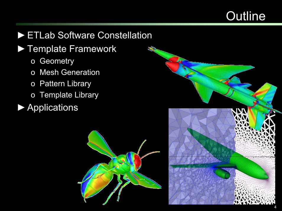
Outline►ETLab Software Constellation►Template Framework
o Geometryo Mesh Generationo Pattern Libraryo Template Library
►Applications
5
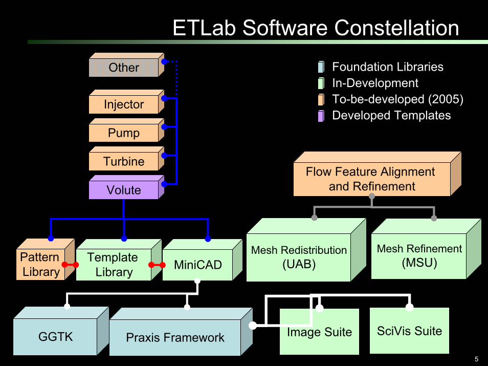
ETLab Software Constellation
MiniCAD
Praxis Framework
Volute
Foundation LibrariesIn-Development To-be-developed (2005)Developed Templates
Flow Feature Alignment and Refinement
Mesh Redistribution(UAB)
Turbine
Pump
Injector
Other
Mesh Refinement(MSU)Template
LibraryPattern Library
GGTK Image Suite SciVis Suite
6
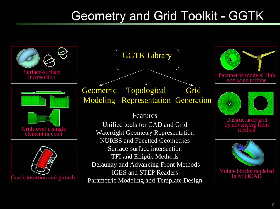
Geometry and Grid Toolkit - GGTK
GGTK Library
Geometric Modeling
Topological Representation
GridGeneration
FeaturesUnified tools for CAD and Grid
Watertight Geometry RepresentationNURBS and Facetted Geometries
Surface-surface intersectionTFI and Elliptic Methods
Delaunay and Advancing Front MethodsIGES and STEP Readers
Parametric Modeling and Template Design
Parametric models: Hub and wind turbine
Unstructured grid by advancing front
method
Volute blocks modeled in MiniCAD
Grids over a single element injector
Crack insertion and growth
Surface-surface intersection

7
Parametric vs. Discrete Geometry►Parametric: IGES, STEP, …►Discrete: STL, OBJ, DXF, …
Report Date: 05/05/2005

8
Parametric Geometry►Geometry entities are individually well-defined analytically►When put together, there may be gaps and other problems,
though.
Report Date: 05/05/2005
9
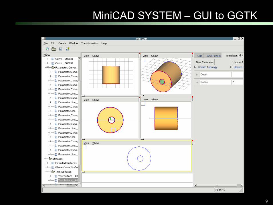
MiniCAD SYSTEM – GUI to GGTK

10
Discrete Geometry
►Facetted or even with only point clouds

11
Praxis Environment► Provide tools to simplify Dynamic GUI example
o cross-platform developmento integration of existing codeso consistency of human interfaceo grid-like remote code interaction
► Design philosophyo Provide everything; require nothing.o Make simple things easy, and difficult things possible.
Praxis Platform
Data Management
Remote Vis
CAD/Geom
PyGame
Numeric
wxPython
Python 2.4 VTK 4.2
etc.
ETLabDemo System
other ad-hoctools
Dock
Praxis GUI
etc PraxisWorkspace

12
Praxis Environment
►The Praxis Workspace o provides a centralized set of high-level GUI tools within
a structured framework to make human interface development simple and consistent.
o The developer is not required to use these tools; they are there to help if needed and to provide a common base for module interoperation
►The Praxis Dock o provides a simple API for modules to discover the
available resources and each other.o provides proxy modules to allow for the seamless
integration of remote modules, accessed the same as local modules.

13
Mesh Types Supported
►Structured►Unstructured►Hybrid►Generalized (MSU)
►Redistribution/ Refinement (MSU)
Drs. David Thompson,Satish Chalasani, MSU

14
Hybrid Mesh Generation►Technical Approach:
oPrismatic layer generation by an advancing layer methodo Starting from a surface mesho Adding multiple normals at sharp corners
oTetrahedral meshing by an advancing front methodo Face swapping based on the Delaunay propertyo Node smoothing by an angle-based smoothing method

15
Surface Mesh Decimation►Function-based mesh coarsening method (3D)
o Miller, G. L. et al., “Optimal Coarsening of Unstructured Meshes,” J of Algorithms, 31: 29-65 1999 (in 2D)
►Spacing function at each node based ono Maximum length of the connected edges o Local surface curvature
o Garimella, R. V. & Swartz, B. K., “Curvature Estimation for Unstructured Triangulations of Surfaces,”LA-UR-03-8240, 2003.
o Local volume thickness

16
Surface Mesh Decimation
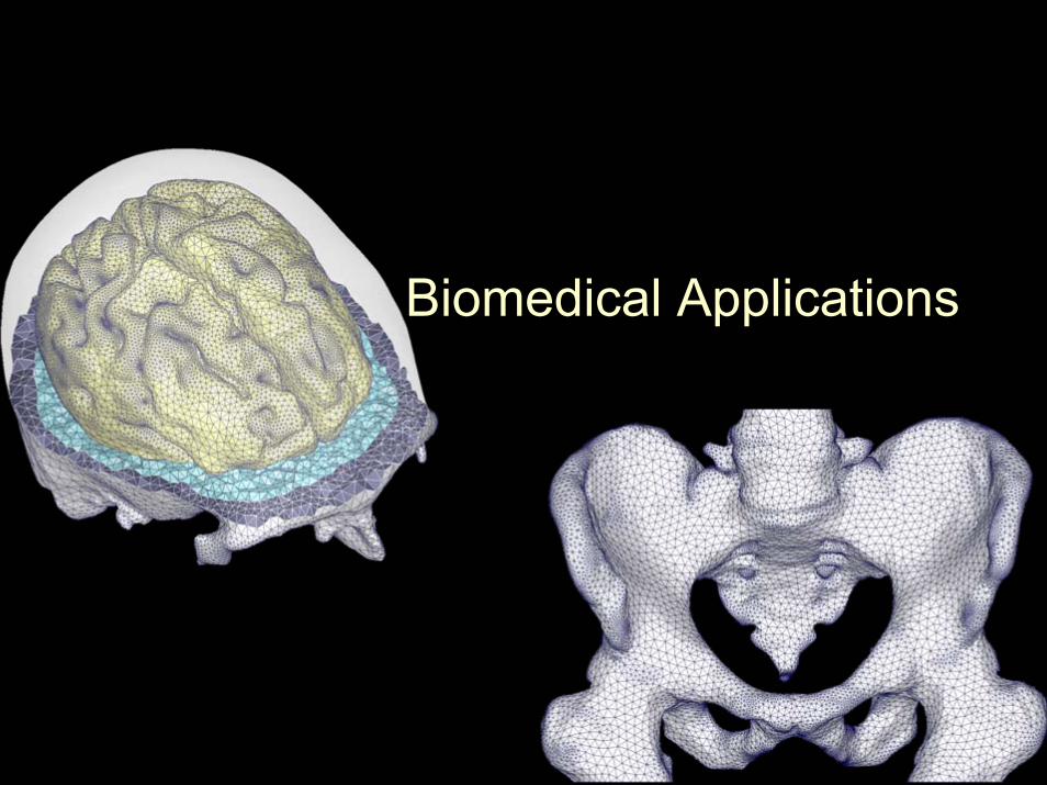
Biomedical Applications
18
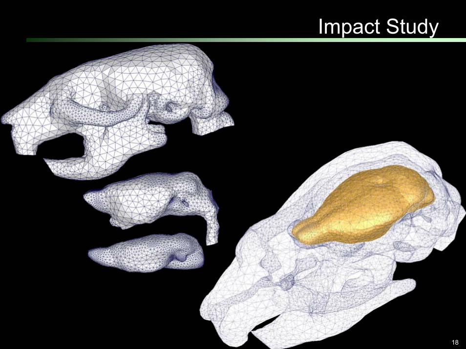
Impact Study

19
Biomedical Engineering Applications

20
Human Skull
21
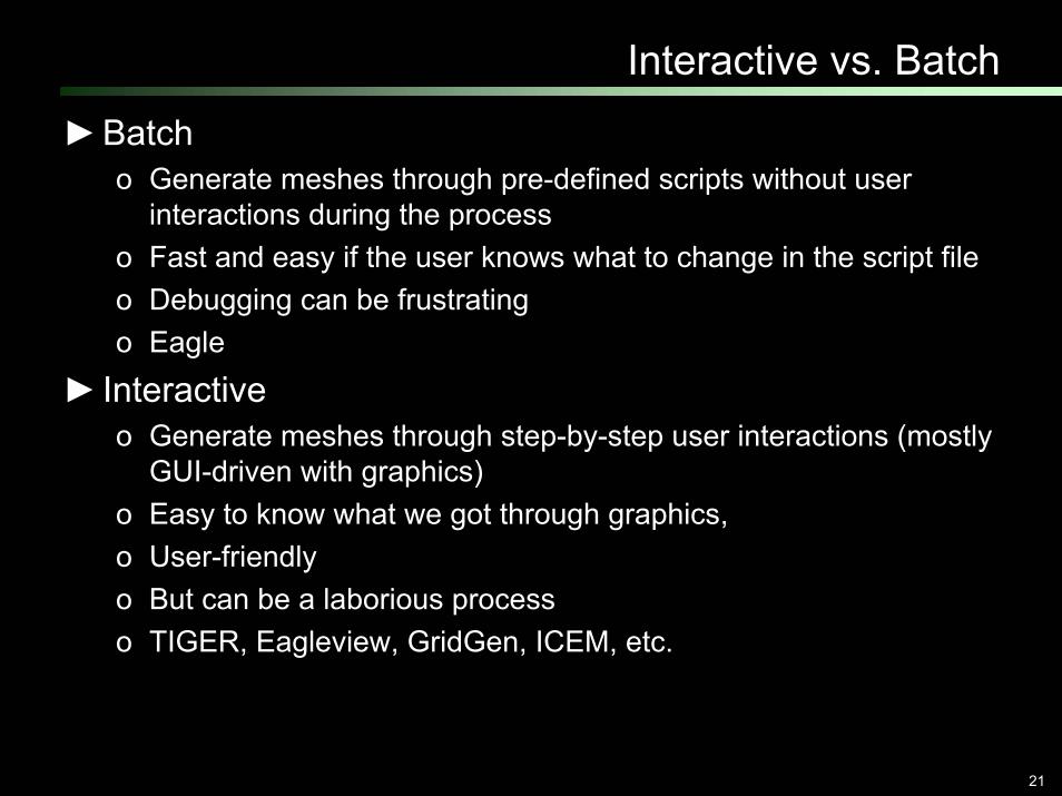
Interactive vs. Batch
►Batcho Generate meshes through pre-defined scripts without user
interactions during the processo Fast and easy if the user knows what to change in the script fileo Debugging can be frustratingo Eagle
► Interactiveo Generate meshes through step-by-step user interactions (mostly
GUI-driven with graphics)o Easy to know what we got through graphics, o User-friendlyo But can be a laborious processo TIGER, Eagleview, GridGen, ICEM, etc.

22
Customized vs. Templates► Customized
o Applicable geometry/ configuration is limited to a certain category
o Many of the steps are automated
o Maintain certain user interactions for modifications
o TIGER► Templates
o Very specific configuration and geometry category
o A lot of the steps are automated (batch)
o Specific/ limited user controlo Volute, SEI, MEI templates

23
Template Framework►Technical Approaches (Phase-I)
o Batch modeo Difficult to useo Programmatic Codingo Tedious and time-consumingo Un-flexible to change geometry definitions and topologyo Examples:
o Single Element Injectors

24
Template Framework►Technical Approaches (Phase-II)
oGUI-driven, graphically interactiveoEasy to useoProgrammatic CodingoLess tedious but time-consuming by accessing features in
MiniCAD and GGTKoUn-flexible to change geometry definitions and topologyoExamples:
o Volute Templates (9 Configurations)o Torus Templates (3 Configurations)

25
Template Framework►Technical Approach (Phase-III, Current)
o GUI –driven and graphically interactiveo Easy to useo Dynamic User-defined GUI for geometry, topology and mesho Automatic update on geometry, topology and mesho XML specificationso Very easy to setup the templateo Very flexible to change the geometry and topology
►Status Report (Demos)o Creating SEI geometryo Creating templateo Creating SEI geometry by relational equations
o Creating template by drag-and-dropo Creating SEI geometry volume
26
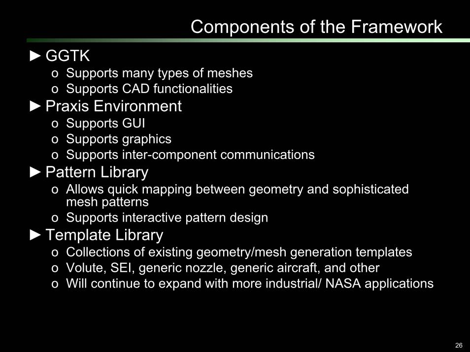
Components of the Framework►GGTK
o Supports many types of mesheso Supports CAD functionalities
►Praxis Environmento Supports GUIo Supports graphicso Supports inter-component communications
►Pattern Libraryo Allows quick mapping between geometry and sophisticated
mesh patternso Supports interactive pattern design
►Template Libraryo Collections of existing geometry/mesh generation templateso Volute, SEI, generic nozzle, generic aircraft, and othero Will continue to expand with more industrial/ NASA applications

27
Template Framework
MiniCAD
Praxis Environment
Injector
Template Library
Pattern Library
GGTK
28
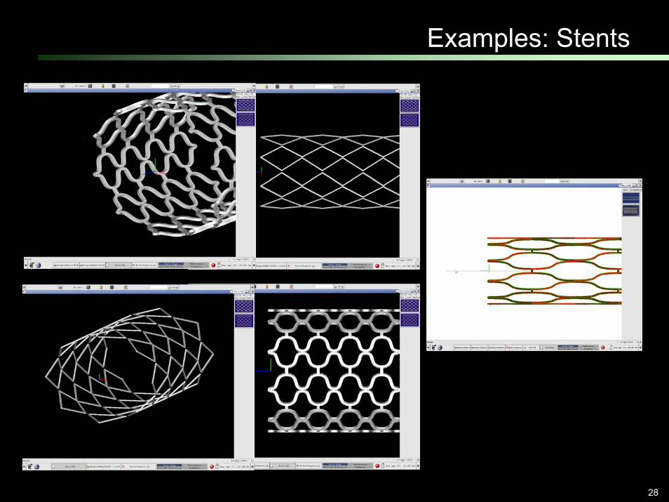
Examples: Stents

29
Demos
►SEI Geometry Creation►SEI Template Creation►Pattern Creation►Pattern Application►Unstructured Volute Template
►Additional Presentationo TUE Afternoono UAB Booth (MON/TUE)

30
Acknowledgement►ME UAB Members
o Dr. S. Gopalsamy (GGTK)o Dr. Yasushi Ito (Unstructured, Hybrid and Parallel Mesh)o Mr. Corey Shum (Praxis, Medical Geometry, SciVis)o Mr. Doug Ross (MiniCAD, IGES)o Mr. Mark Dillavou (Praxis, MiniCAD, SciVis)o Mr. Dipesh Dimble (MS Student, Stent Template)
►Tohoku University (Japan)o Dr. Kazuhiro Nakahashi
►MSUo Dr. David Thompson
►Funding supported byo NASA CUIP Programo DoD PET Programo NSF ITR Program