
Geometric Design Guidance - mdotcf.state.mi.us · Geometric Design Table of Contents 1.0...
57
Geometric Design Guidance PREPARED BY TRAFFIC AND SAFETY September 2017
Transcript of Geometric Design Guidance - mdotcf.state.mi.us · Geometric Design Table of Contents 1.0...
Geometric Design Guidance
PREPARED BY TRAFFIC AND SAFETY
September 2017
Engineering Manual Preamble
This manual provides guidance to administrative, engineering, and technical staff. Engineering practice requires that professionals use a combination of technical skills and judgment in decision making. Engineering judgment is necessary to allow decisions to account for unique site-specific conditions and considerations to provide high quality products, within budget, and to protect the public health, safety, and welfare. This manual provides the general operational guidelines; however, it is understood that adaptation, adjustments, and deviations are sometimes necessary. Innovation is a key foundational element to advance the state of engineering practice and develop more effective and efficient engineering solutions and materials. As such, it is essential that our engineering manuals provide a vehicle to promote, pilot, or implement technologies or practices that provide efficiencies and quality products, while maintaining the safety, health, and welfare of the public. It is expected when making significant or impactful deviations from the technical information from these guidance materials, that reasonable consultations with experts, technical committees, and/or policy setting bodies occur prior to actions within the timeframes allowed. It is also expected that these consultations will eliminate any potential conflicts of interest, perceived or otherwise. MDOT Leadership is committed to a culture of innovation to optimize engineering solutions.
The National Society of Professional Engineers Code of Ethics for Engineering is founded on six fundamental canons. Those canons are provided below.
Engineers, in the fulfillment of their professional duties, shall:
1. Hold paramount the safety, health, and welfare of the public. 2. Perform Services only in areas of their competence. 3. Issue public statement only in an objective and truthful manner. 4. Act for each employer or client as faithful agents or trustees. 5. Avoid deceptive acts. 6. Conduct themselves honorably, reasonably, ethically and lawfully so as to enhance the
honor, reputation, and usefulness of the profession.
INTRODUCTION TO GEOMETRIC DESIGN The following are intended to provide guidance relating to a variety of traffic safety and operational issues and/or needs. This includes geometric design guidance, traffic volume warranting criteria, and direction regarding the submission and review of various analyses and reports. Many of these sections include hyperlinks and/or references to other source material which provide additional details regarding the subject of interest. Included among these other reference sources are the Michigan Department of Transportation (MDOT) Geometric Design Guides and the Michigan Road Design Manual. The use of such other reference sources in conjunction with this guidance is strongly encouraged, as they typically provide a much greater level of detail than that which is found in the various sections. Most the geometric guidance is divided into two broad categories: Operational Considerations and Safety Considerations. Within these two categories, the sections are further sub-divided into Intersection Treatments and Corridor/Midblock Treatments. There are a few sections categorized as Miscellaneous Considerations. These did not fit neatly into either of the first two categories. The Miscellaneous Considerations are further sub-divided into sections relating to Parking, Studies and Analyses, and Lighting. The intent of this categorization is to allow the reader of this guidance to quickly reference the appropriate treatments and/or countermeasures to a variety of traffic issues, be they operations related or safety related. It should be noted that there is a great deal of overlap within the sections. This was done intentionally, because traffic operations and traffic safety are intrinsically linked to each other. Many of the treatments that can be considered primarily as operational improvements also have the effect of improving traffic safety. Conversely, many of the treatments considered primarily as safety improvements also have the effect of improving traffic operations. Therefore, many of the sections appear in both categories.

This page is intentionally blank.
Geometric Design Table of Contents
1.0 Operational Considerations
1.1 Intersection Treatments 1.1.1 Required Intersection Widening to Accommodate New Traffic Signals 1.1.2 Divided Roadway Intersections 1.1.3 Clear Vision Areas 1.1.4 Traffic Volume Guidelines for Right-Turn Lanes and Tapers 1.1.5 Traffic Volume Guidelines for Left-Turn Lanes and Passing Flares 1.1.6 Near Side/Far Side Lane Drops 1.1.7 Roundabouts
1.2 Corridor Treatments 1.2.1 Roadside Traffic Control Islands 1.2.2 Spacing for Commercial Drives and Streets 1.2.3 Traffic Volume Guidelines for Driveway Passing Flares 1.2.4 Traffic Impact Studies 1.2.5 Traffic Impact Assessments 1.2.6 Truck Route Classification Considerations
2.0 Safety Considerations
2.1 Intersection Treatments 2.1.1 Traffic Volume Guidelines for Right-Turn Lanes and Tapers 2.1.2 Traffic Volume Guidelines for Left-Turn Lanes and Passing Flares 2.1.3 Clear Vision Areas 2.1.4 Roundabouts
2.2 Corridor Treatments
2.2.1 Roadside Traffic Control Islands 2.2.2 Traffic Volume Guidelines for Driveway Passing Flares 2.2.3 On-Street Angled Parking
3.0 Miscellaneous Considerations
3.1 Parking 3.1.1 On-Street Angled Parking 3.1.2 Parking Facility Dimensions
3.2 Studies and Analyses
3.2.1 Design Exception/Variance 3.2.2 Truck Route Classification Considerations 3.2.3 Traffic Impact Studies 3.2.4 Traffic Impact Assessments
3.3 Lighting
3.3.1 Non-Freeway Lighting 3.3.2 Freeway Lighting 3.3.3 Illumination at Railroad Crossings

This page is intentionally blank.
1.0 OPERATIONAL CONSIDERATIONS
The following are related primarily to traffic operational issues. The sections are divided into two types of treatments: Intersection Treatments and Corridor/Midblock Treatments. It should be noted that while this guidance typically pertains to traffic operational issues, many of these treatments provide tangible traffic safety benefits as well as operational improvements. 1.0 Operational Considerations
1.1 Intersection Treatments 1.1.1 Required Intersection Widening to Accommodate New Traffic Signals 1.1.2 Divided Roadway Intersections 1.1.3 Clear Vision Areas 1.1.4 Traffic Volume Guidelines for Right-Turn Lanes and Tapers 1.1.5 Traffic Volume Guidelines for Left-Turn Lanes and Passing Flares 1.1.6 Near Side/Far Side Lane Drops 1.1.7 Roundabouts
1.2 Corridor/Midblock Treatments 1.2.1 Roadside Traffic Control Islands 1.2.2 Spacing for Commercial Drives and Streets 1.2.3 Traffic Volume Guidelines for Driveway Passing Flares 1.2.4 Traffic Impact Studies 1.2.5 Traffic Impact Assessments 1.2.6 Truck Route Classification Considerations

1.1.1 Required Intersection Widening to Accommodate New Signals
When a “Stop-and-Go” traffic signal is installed at an intersection, the capacity of the through roadway is reduced by about half. In addition, left turning traffic can interlock, effectively stopping all through traffic. As a result, prior to the installation of a “Stop-and-Go” traffic signal, all legs of the intersection should have a minimum of two approach lanes. Additional widening may be required to provide for capacity. An alternative to widening would be to prohibit left turns or provide for one way streets. If widening is required, it shall be done in accordance with MDOT Geometric Design Guide GEO-650. The crossroad shall provide a minimum of two approach lanes also. The crossroad widening shall be the responsibility of, and financed by, the roadway authority. At locations with a single approach lane, intersection widening will typically be required in order to obtain two approach lanes as required to accommodate a new traffic signal.
1.1.2 Divided Roadway Intersections
The Legal definition of an intersection at/of a divided roadway is dependent on the dividing distance. The Michigan Vehicle Code (P.A. 300, 1949, as amended) Section 257.22 provides that “where a highway includes two roadways 30 feet or more apart, then every crossing of each roadway of such divided highway by an intersecting highway shall be regarded as a separate intersection. In the event such intersecting highway also includes two roadways 30 feet or more apart, then every crossing of two roadways of such highways shall be regarded as a separate intersection” (emphasis added). This legal definition of an intersection depends on the distance between the traveled portions (defined as “roadway” in the Vehicle code) of the highway and becomes important in some cases of traffic control. For example, the regulatory sign COMPLETE LEFT TURN WHEN TRAFFIC CLEARS is limited to applications where the median width is less than 30 feet (one intersection). Interpretation of Section 257.22 defining intersections indicates that the median width should be considered as:
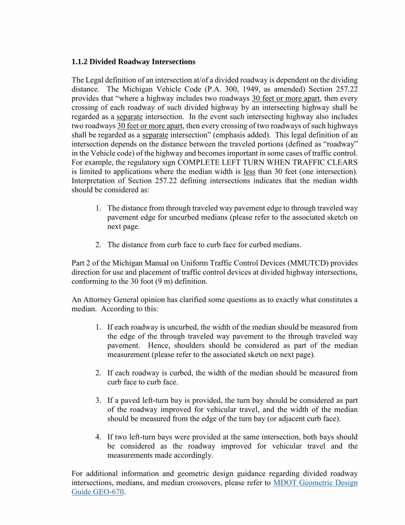
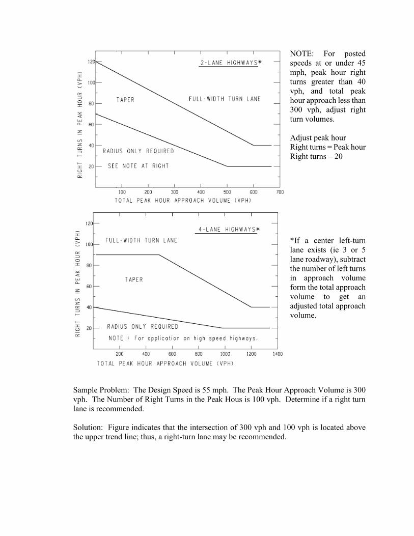
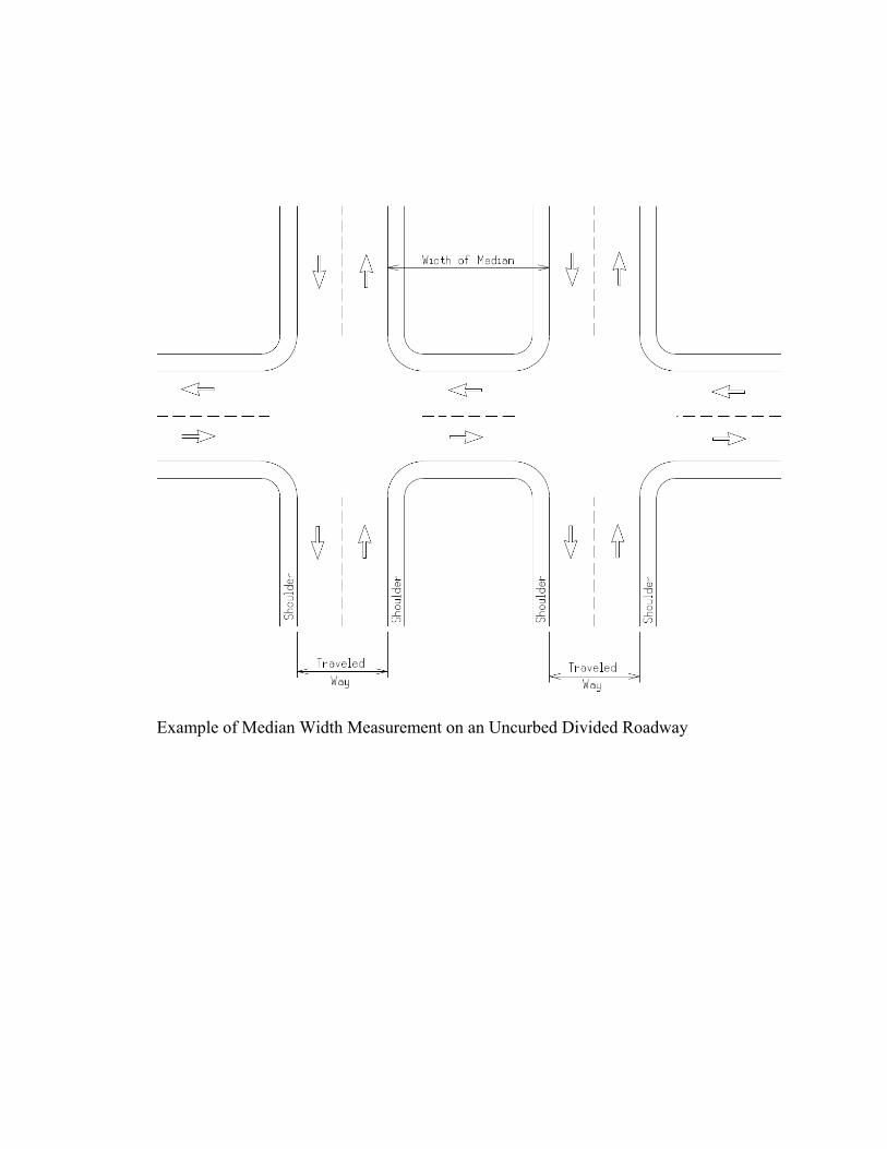
1. The distance from through traveled way pavement edge to through traveled way pavement edge for uncurbed medians (please refer to the associated sketch on next page.
2. The distance from curb face to curb face for curbed medians.
Part 2 of the Michigan Manual on Uniform Traffic Control Devices (MMUTCD) provides direction for use and placement of traffic control devices at divided highway intersections, conforming to the 30 foot (9 m) definition. An Attorney General opinion has clarified some questions as to exactly what constitutes a median. According to this:
1. If each roadway is uncurbed, the width of the median should be measured from
the edge of the through traveled way pavement to the through traveled way pavement. Hence, shoulders should be considered as part of the median measurement (please refer to the associated sketch on next page).
2. If each roadway is curbed, the width of the median should be measured from
curb face to curb face. 3. If a paved left-turn bay is provided, the turn bay should be considered as part
of the roadway improved for vehicular travel, and the width of the median should be measured from the edge of the turn bay (or adjacent curb face).
4. If two left-turn bays were provided at the same intersection, both bays should
be considered as the roadway improved for vehicular travel and the measurements made accordingly.
For additional information and geometric design guidance regarding divided roadway intersections, medians, and median crossovers, please refer to MDOT Geometric Design Guide GEO-670.
Example of Median Width Measurement on an Uncurbed Divided Roadway
1.1.3 Clear Vision Areas
In order to enhance the safe and efficient movement of traffic, the acquisition of certain properties (or portions thereof) at intersections sometimes is necessary. The following guidelines should be followed. Clear vision areas will be obtained at all at-grade intersections of trunklines with other roads or streets in rural areas including freeway ramps. Interchange ramps are considered trunkline. Clear vision areas will not be obtained within urban areas as determined by the Bureau of Transportation Planning's urban area boundary description and map. Clear vision areas will not be obtained within rural areas contiguous to sections of trunkline where urban conditions exist to the extent that 50 percent or more of the trunkline frontage is occupied by residential, business, or industrial development. The Region/TSC Traffic and Safety Representative reviews each case from a traffic operational and safety standpoint and recommends one of the following courses of action: acquire all or part of area, defer acquisition in particular quadrant to future date, or eliminate all clear vision. For additional information and guidance regarding clear vison areas, please refer to MDOT Geometric Design Guide GEO-300 and the Michigan Road Design Manual, Chapter 5. Right Of Way.
1.1.4 Traffic Volume Guidelines for Right-Turn Lanes and Tapers
The addition of right-turn lanes or tapers at intersections should be considered to enhance the traffic movements and improve traffic operations and safety. Exclusive right-turn lanes should be considered. The following traffic volume guidelines have been established and are outlined below.
Guidelines for Right-Turn Lanes and Tapers The use of right-turn lanes or tapers should be considered in the following conditions:
1. At any intersection where a capacity analysis determines a right-turn lane or
taper is necessary to meet a desired level of service. 2. At any intersection where the crash experience, existing traffic operations or
engineering judgment indicates that a right-turn lane or taper will significantly improve operations.
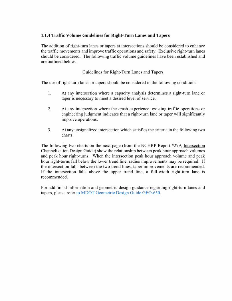
3. At any unsignalized intersection which satisfies the criteria in the following two
charts. The following two charts on the next page (from the NCHRP Report #279, Intersection Channelization Design Guide) show the relationship between peak hour approach volumes and peak hour right-turns. When the intersection peak hour approach volume and peak hour right-turns fall below the lower trend line, radius improvements may be required. If the intersection falls between the two trend lines, taper improvements are recommended. If the intersection falls above the upper trend line, a full-width right-turn lane is recommended. For additional information and geometric design guidance regarding right-turn lanes and tapers, please refer to MDOT Geometric Design Guide GEO-650.
NOTE: For posted speeds at or under 45 mph, peak hour right turns greater than 40 vph, and total peak hour approach less than 300 vph, adjust right turn volumes. Adjust peak hour Right turns = Peak hour Right turns – 20 *If a center left-turn lane exists (ie 3 or 5 lane roadway), subtract the number of left turns in approach volume form the total approach volume to get an adjusted total approach volume.
Sample Problem: The Design Speed is 55 mph. The Peak Hour Approach Volume is 300 vph. The Number of Right Turns in the Peak Hous is 100 vph. Determine if a right turn lane is recommended. Solution: Figure indicates that the intersection of 300 vph and 100 vph is located above the upper trend line; thus, a right-turn lane may be recommended.
Example of Median Width Measurement on an Uncurbed Divided Roadway
1.1.5 Traffic Volume Guidelines for Left-Turn Lanes and
Passing Flares at Unsignalized Intersections
The addition of left-turn lanes or passing flares should be considered in order to enhance the traffic operations and safety at intersections. MDOT has established guidelines for the consideration of these intersection treatments, as provided in the following charts. The first three charts display the relationship between advancing and opposing volumes with respect to left-turns on two-lane, two-way highways. For each of the three charts, if the intersection of advancing and opposing volumes falls to the right of the curve representing the percentage of left-turns in the advancing volume, a left-turn lane is recommended. If the intersection falls to the left of the curve, a left-turn lane is not recommended. If a left-turn lane is not recommended, consider the installation of a passing flare. For additional information and geometric design guidance regarding left-turn lanes and passing flares, please refer to MDOT Geometric Design Guide GEO-650. The fourth chart displays the relationship between the left-turning volumes and opposing volumes on four-lane, undivided highways. A left-turn lane is generally not warranted if the intersection of left-turning volumes and opposing volumes falls within the shaded area. These charts are taken from NCHRP Report 279, Intersection Design Guide.
Guidelines for Left-Turn Lanes on Two-Lane, Two-Way Highways
and Four-Lane, Undivided Highways
The accommodation of left turns is often the critical factor in proper intersection design. Left-turn lanes and passing flares can significantly improve safety and the level of service at an intersection. Exclusive left-turn lanes should be considered under the following conditions: 1. At any unsignalized intersection on a two-lane urban or rural highway which
satisfies the criteria in the first three charts.
2. At any unsignalized intersections on a four-lane urban or rural highway which satisfies the criteria in the fourth chart.
3. At any intersection where the crash experience, traffic operations, sight distance
restrictions (e.g., intersection beyond a crest vertical curve), or engineering judgment indicates that a left-turn lane will significantly improve operations.
If a left-turn lane is not recommended, a passing flare should be considered. Passing flares are discussed in Section 1.2.3 and Section 2.2.2 of this document.
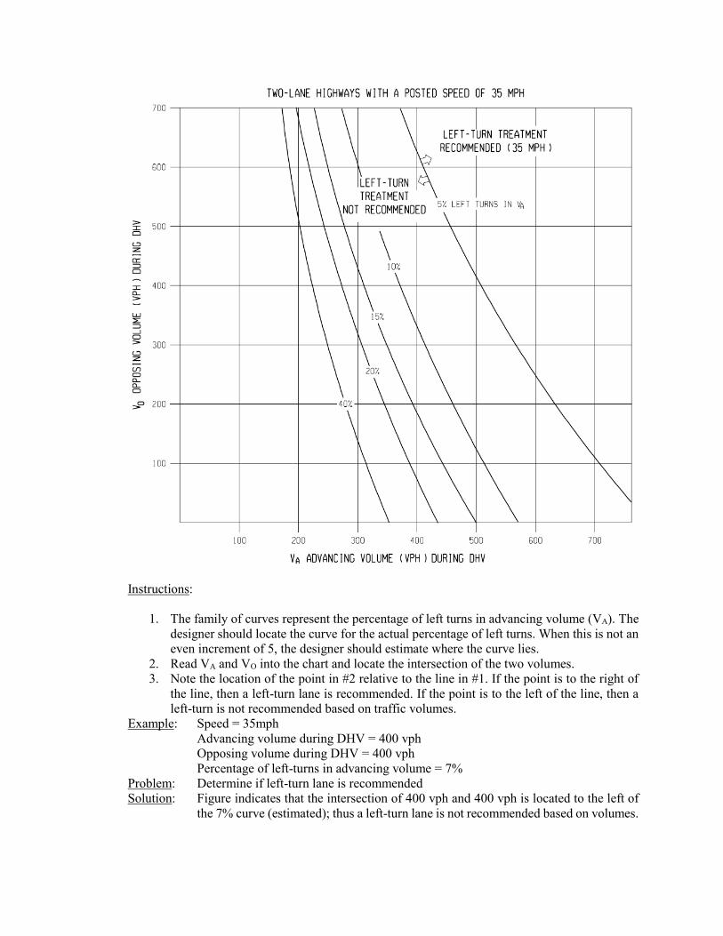
Instructions:
1. The family of curves represent the percentage of left turns in advancing volume (VA). The designer should locate the curve for the actual percentage of left turns. When this is not an even increment of 5, the designer should estimate where the curve lies.
2. Read VA and VO into the chart and locate the intersection of the two volumes. 3. Note the location of the point in #2 relative to the line in #1. If the point is to the right of
the line, then a left-turn lane is recommended. If the point is to the left of the line, then a left-turn is not recommended based on traffic volumes.
Example: Speed = 35mph Advancing volume during DHV = 400 vph Opposing volume during DHV = 400 vph Percentage of left-turns in advancing volume = 7% Problem: Determine if left-turn lane is recommended Solution: Figure indicates that the intersection of 400 vph and 400 vph is located to the left of
the 7% curve (estimated); thus a left-turn lane is not recommended based on volumes.
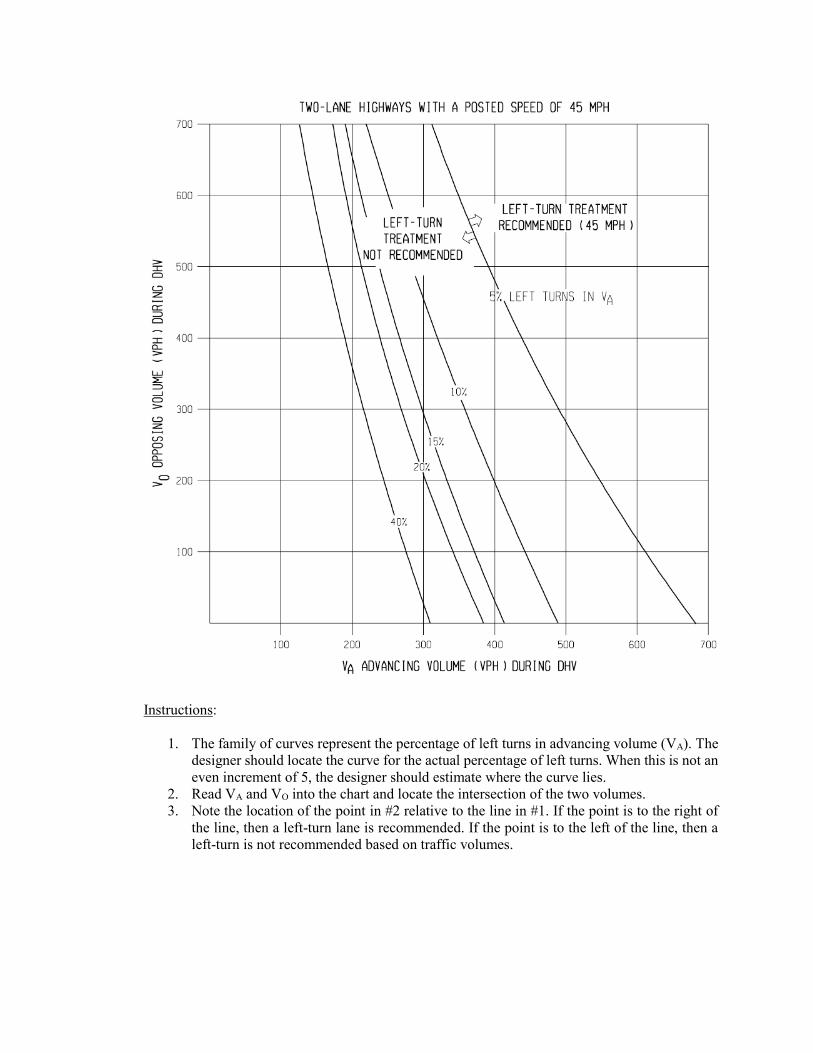
Instructions:
1. The family of curves represent the percentage of left turns in advancing volume (VA). The designer should locate the curve for the actual percentage of left turns. When this is not an even increment of 5, the designer should estimate where the curve lies.
2. Read VA and VO into the chart and locate the intersection of the two volumes. 3. Note the location of the point in #2 relative to the line in #1. If the point is to the right of
the line, then a left-turn lane is recommended. If the point is to the left of the line, then a left-turn is not recommended based on traffic volumes.
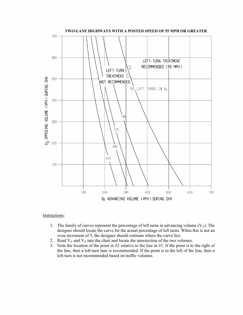
TWO-LANE HIGHWAYS WITH A POSTED SPEED OF 55 MPH OR GREATER
Instructions:
1. The family of curves represent the percentage of left turns in advancing volume (VA). The designer should locate the curve for the actual percentage of left turns. When this is not an even increment of 5, the designer should estimate where the curve lies.
2. Read VA and VO into the chart and locate the intersection of the two volumes. 3. Note the location of the point in #2 relative to the line in #1. If the point is to the right of
the line, then a left-turn lane is recommended. If the point is to the left of the line, then a left-turn is not recommended based on traffic volumes.
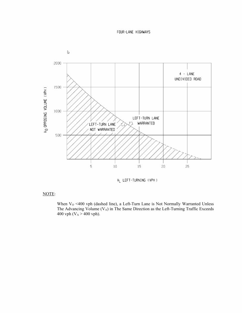
NOTE:
When VO <400 vph (dashed line), a Left-Turn Lane is Not Normally Warranted Unless The Advancing Volume (VA) in The Same Direction as the Left-Turning Traffic Exceeds 400 vph (VA > 400 vph).
1.1.6 Near Side/Far Side Lane Drops
The following guidelines, based on an ITE report, are qualitative in order to encourage the evaluation of lane drops at intersections on an individual basis: General 1. Engineering judgment is the primary basis for determining the appropriate intersection lane
drop, near-side or far-side. Additionally, engineering judgment should prevail when applying the distances recommended in these guidelines to specific traffic conditions.
2. Intersection capacity, intersection turning volumes (especially right turns), parking and
right of way restrictions, design speed, lighting, and safety are significant considerations in the evaluation of the appropriate intersection lane drop, either near-side or far-side.
3. The Decision Sight Distance concept is applicable to the geometric design and placement
of traffic control devices for both near-side and far-side intersection lane drops. 4. Intersection lane drops present the driver with a high judgment, complex driving situation
and, therefore, the most effective signing and pavement marking is recommended (please refer to the appropriate figures).
5. Far-side intersection lane drops are preferred over near-side. To some extent both types of
lane drops have been used for different purposes (far-side for capacity; near-side for operations).
6. Intersection lane drops can be associated with an interim condition before a highway
widening is extended at a future date. If it is planned to continue the widening, a far-side lane drop has the advantage of placing the beginning of the new construction well beyond the intersection (please refer to the appropriate figures).
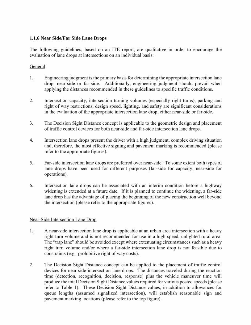
Near-Side Intersection Lane Drop 1. A near-side intersection lane drop is applicable at an urban area intersection with a heavy
right turn volume and is not recommended for use in a high speed, unlighted rural area. The “trap lane” should be avoided except where extenuating circumstances such as a heavy right turn volume and/or where a far-side intersection lane drop is not feasible due to constraints (e.g. prohibitive right of way costs).
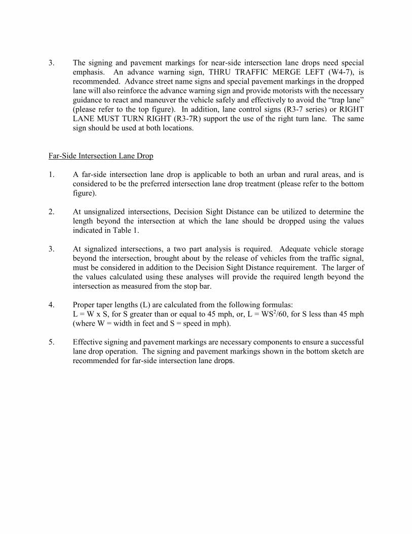
2. The Decision Sight Distance concept can be applied to the placement of traffic control
devices for near-side intersection lane drops. The distances traveled during the reaction time (detection, recognition, decision, response) plus the vehicle maneuver time will produce the total Decision Sight Distance values required for various posted speeds (please refer to Table 1). These Decision Sight Distance values, in addition to allowances for queue lengths (assumed signalized intersection), will establish reasonable sign and pavement marking locations (please refer to the top figure).
3. The signing and pavement markings for near-side intersection lane drops need special
emphasis. An advance warning sign, THRU TRAFFIC MERGE LEFT (W4-7), is recommended. Advance street name signs and special pavement markings in the dropped lane will also reinforce the advance warning sign and provide motorists with the necessary guidance to react and maneuver the vehicle safely and effectively to avoid the “trap lane” (please refer to the top figure). In addition, lane control signs (R3-7 series) or RIGHT LANE MUST TURN RIGHT (R3-7R) support the use of the right turn lane. The same sign should be used at both locations.
Far-Side Intersection Lane Drop 1. A far-side intersection lane drop is applicable to both an urban and rural areas, and is
considered to be the preferred intersection lane drop treatment (please refer to the bottom figure).
2. At unsignalized intersections, Decision Sight Distance can be utilized to determine the
length beyond the intersection at which the lane should be dropped using the values indicated in Table 1.
3. At signalized intersections, a two part analysis is required. Adequate vehicle storage
beyond the intersection, brought about by the release of vehicles from the traffic signal, must be considered in addition to the Decision Sight Distance requirement. The larger of the values calculated using these analyses will provide the required length beyond the intersection as measured from the stop bar.
4. Proper taper lengths (L) are calculated from the following formulas: L = W x S, for S greater than or equal to 45 mph, or, L = WS2/60, for S less than 45 mph
(where W = width in feet and S = speed in mph). 5. Effective signing and pavement markings are necessary components to ensure a successful
lane drop operation. The signing and pavement markings shown in the bottom sketch are recommended for far-side intersection lane drops.
Advance placement distance (d): See Traffic Sign Design Placement, and Application Guidelines (TSDPAG) Table 3: Condition A. See PAVE Standards for pavement marking details.
Decision Sight Distance
Table 1
1.1.7 Roundabouts
Roundabouts are a circular form of intersection design increasingly being utilized in the United States, including by the Michigan Department of Transportation. Roundabouts differ from more conventional intersection types in their geometry, traffic control, and traffic operations. When appropriately sited, roundabouts can provide better operational efficiencies and greater safety benefits than traditional intersection designs. Roundabout design is somewhat site-specific; there is no “one-size-fits-all” approach. However, there are certain universal characteristics which define all modern roundabouts. Some of the more significant elements common to properly designed roundabouts include:
• Counterclockwise Flow – All traffic travels in a counterclockwise direction around a central “island”.
• Deflected Entries – The approaches to the roundabout are deflected, or curved, in the
direction of the circulatory roadway; they do not intersect at 90 degree angles. This facilitates a smooth entry into the roundabout.
• Yield Control on Entries – All traffic entering the roundabout must yield right-of-way to traffic already circulating within the roundabout.
• Low-Speeds – The alignment and curvature of the roundabout results in low-speed operations (generally in the 15-25 mph range) throughout the roundabout.
Because of their low operating speeds, acute impact angles, and reduced number of conflict points, roundabouts substantially reduce fatal and severe injury traffic crashes. Per the AASHTO Highway Safety Manual, roundabouts reduce severe injury and fatal crashes by 78 percent to 82 percent as compared to conventional stop-controlled or signalized intersections. Before-and-after studies conducted on Michigan roundabouts identified reductions in injury crashes for all classes of roundabout conversions. The analysis estimated injury crash reductions that range from a low of 20 percent for signalized intersections converted to three-lane roundabouts to a high of 70 percent for signalized intersections converted to one- and two-lane roundabouts. One or two-way stop controlled intersections converted to roundabouts displayed a 40 percent reduction in injury crashes while all-way stop controlled intersections converted to a roundabout had a 36 percent reduction. While researchers identified an overall increase in crashes for most types of roundabout conversions, the reduction in injury crashes provides a net crash cost benefit for most conversion types. Researchers calculated a return on investment of less than two years for all three types of roundabouts, attributing this relatively quick return to the significant reduction in crashes and the benefits associated with reductions in user delay. Furthermore, roundabouts are designed to improve safety for all road users, including pedestrians and bicyclists. For these reasons, the FHWA Office of Safety has identified roundabouts as a “Proven Safety Countermeasure”.
As stated previously, roundabout design is site-dependent. Proper design often requires the incorporation of some design flexibility and allowances, tempered by engineering judgment and sound design principles. For this reason, it is beyond the scope of this document to provide firm, specific design parameters and values. Instead, reference should be made to NCHRP Report 672 (Roundabouts: An Informational Guide, Second Edition) for detailed information regarding the planning, siting, design, and operation of roundabouts. NCHRP Report 672 is the Michigan Department of Transportation’s preferred source for roundabout guidance. The principles, techniques, and design parameters put forth in NCHRP Report 672 regarding the planning and design of roundabouts are consistent with, and supported by, the department.
1.2.1 Roadside Traffic Control Islands
Roadside traffic control islands should be considered at those locations where it is apparent that their installation will enhance traffic operations and safety. Roadside traffic control islands should be considered in the following situations: 1. The location has a history of traffic crashes correctable by traffic islands. 2. Crash potential exists, as evidenced by disorganized parking along the roadside
where vehicles create conflicts as they move in and out of the traffic main stream. 3. Crash potential is evidenced by parked cars blocking vision. 4. Vehicles backing onto the highway or making other erratic maneuvers interfere
with the smooth flow of traffic. 5. Vehicular movements to private property within the vicinity of an intersection
disrupt traffic. 6. Grade differential between the highway and a roadside business requires roadside
control to organize movements into a desired location and/or path.
7 Driveways are undefined or are not in accordance with current guides. The curb type used in the construction of traffic control islands should be in accordance with current MDOT guidelines. Please refer to the Michigan Road Design Manual, Section 6.06 Curb and Gutter for additional information regarding curb and gutter selection. The full shoulder should be paved between the roadway and the island, where applicable.
1.2.2 Spacing for Commercial Drives and Streets
The spacing of access for commercial driveways and streets is an important element in the planning, design, and operation of roadways. Access points are the main location of crashes and congestion. Their location and spacing directly affect the safety and functional integrity of the roadway. Region Review: The Region/TSC Utility and Permit Engineer shall forward the site plan and the access request to the Region/TSC Traffic and Safety Representative for review. In general, one access point is adequate for a single business. When one-way pair driveways (In-Out) are requested and the inside traffic circulation promotes such operation, these driveways may be considered as a single access point. In some cases multiple access points are requested. In this case, the Region/TSC Traffic and Safety Representative may require a traffic impact study from the business owner/property owner to justify the need for the multiple accesses. A copy of the following information may be sent to the business owner/property owner to outline the traffic analysis needed. Unsignalized Access Spacing: Adjacent accesses should be spaced as far apart as on-site circulation allows. In some cases the Region/TSC Traffic and Safety Representative may require that the business owner/property owner redesign his site plan, and relocate the access point to meet the desirable spacing distance. Table 1 shows the desirable unsignalized access spacing as a function of posted speed. These distances are based on average acceleration and deceleration considered adequate to maintain good traffic operations. The sight distance at the access points must also be investigated.
Posted Speed mph (km/hr)
Center-to-Center of Access feet (meters)
25 (40) 130 (40) 30 (50) 185 (55) 35 (60) 245 (75) 40 (60) 300 (90) 45 (70) 350 (105)
50 (80) and above 455 (140)
Table 1
Lack of Sufficient Frontage to Maintain Adjacent Spacing: In the event that a particular parcel lacks sufficient frontage to maintain adequate spacing, the Region/TSC Traffic and Safety and Utility and Permit Engineers have the following options.
1. Choose the next lowest spacing from Table 1. For example, on 30 mph (50 km/hr) roadway requiring 185 ft (56 m) spacing, the distance may be reduced to no less than 130 ft (40 m) which is the spacing from 25 mph (40 km/hr) speed.
2. Encourage a shared driveway with the adjacent owners. In such case the
driveway midpoint may be located at the property line between two parcels.
However, all parties must agree to the joint driveway in writing.
3. Provide an access point to the side street when it is possible.
4. In areas where frontage roads or service drives exist or can be constructed,
individual properties shall be provided access to these drives rather than directly
to the main highway.
5. After all the above options are exhausted, an access point may be allowed
within the property limits as determined by the Region/TSC Traffic and Safety
and the Utility and Permit Engineers.
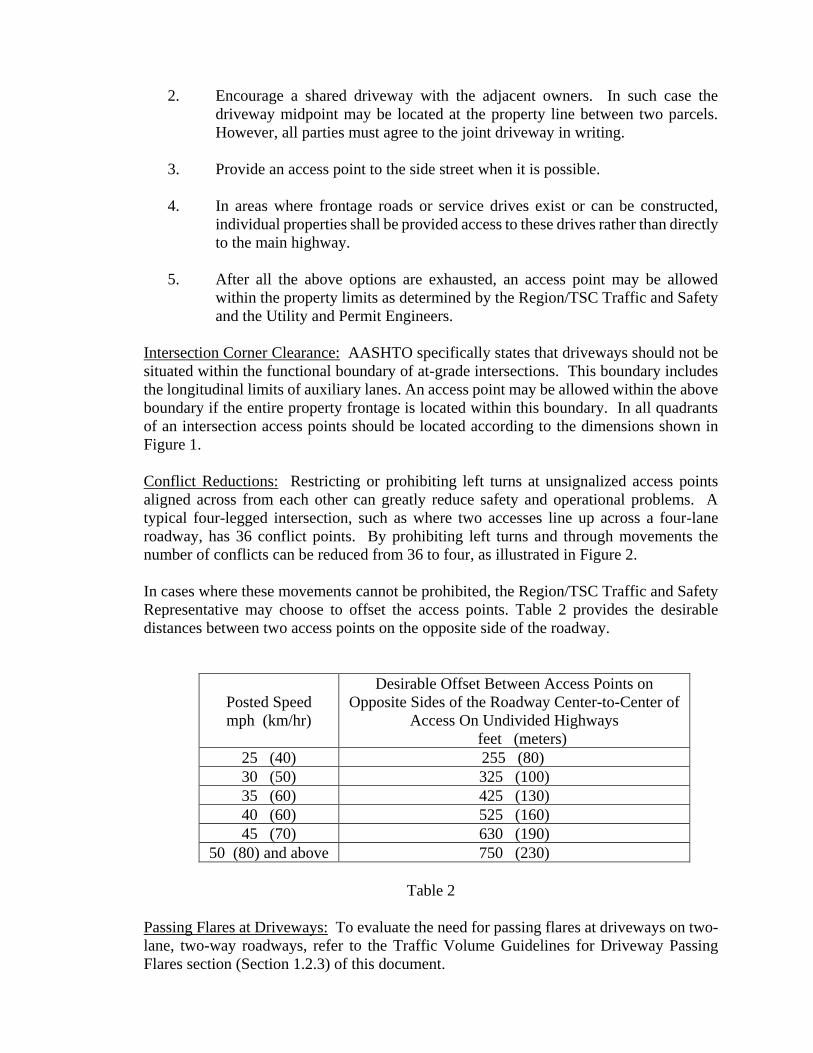
Intersection Corner Clearance: AASHTO specifically states that driveways should not be
situated within the functional boundary of at-grade intersections. This boundary includes
the longitudinal limits of auxiliary lanes. An access point may be allowed within the above
boundary if the entire property frontage is located within this boundary. In all quadrants
of an intersection access points should be located according to the dimensions shown in
Figure 1.
Conflict Reductions: Restricting or prohibiting left turns at unsignalized access points
aligned across from each other can greatly reduce safety and operational problems. A
typical four-legged intersection, such as where two accesses line up across a four-lane
roadway, has 36 conflict points. By prohibiting left turns and through movements the
number of conflicts can be reduced from 36 to four, as illustrated in Figure 2.
In cases where these movements cannot be prohibited, the Region/TSC Traffic and Safety
Representative may choose to offset the access points. Table 2 provides the desirable
distances between two access points on the opposite side of the roadway.
Posted Speed
mph (km/hr)
Desirable Offset Between Access Points on
Opposite Sides of the Roadway Center-to-Center of
Access On Undivided Highways
feet (meters)
25 (40) 255 (80)
30 (50) 325 (100)
35 (60) 425 (130)
40 (60) 525 (160)
45 (70) 630 (190)
50 (80) and above 750 (230)
Table 2
Passing Flares at Driveways: To evaluate the need for passing flares at driveways on two-
lane, two-way roadways, refer to the Traffic Volume Guidelines for Driveway Passing
Flares section (Section 1.2.3) of this document.
Right-turn Lanes or Tapers at Intersection: The addition of right-turn lanes or tapers should
be considered to enhance the movement of traffic through intersections. To evaluate the
need for right-turn lanes and tapers, refer to the Traffic Volume Guidelines for Right-Turn
Lanes and Tapers section (Section 1.1.4) of this document.
Left-Turn Lanes or Passing Flares at Intersections: To evaluate the need for left-turn lanes
or passing flares at intersections, refer to the Traffic Volume Guidelines for Left-Turn
Lanes and Passing Flares at Unsignalized Intersections section (Section 1.1.5) of this
document.
Access Design: All access points shall be designed to meet the Michigan Department of
Transportation guides, standards and Construction Permit Manual.
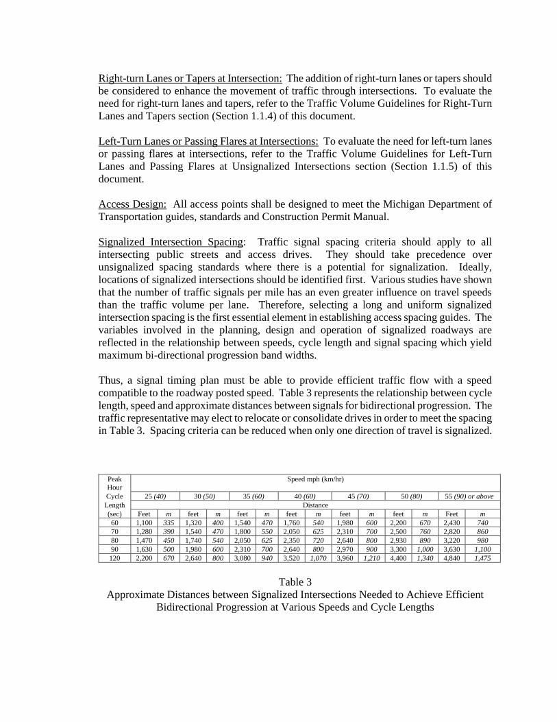
Signalized Intersection Spacing: Traffic signal spacing criteria should apply to all
intersecting public streets and access drives. They should take precedence over
unsignalized spacing standards where there is a potential for signalization. Ideally,
locations of signalized intersections should be identified first. Various studies have shown
that the number of traffic signals per mile has an even greater influence on travel speeds
than the traffic volume per lane. Therefore, selecting a long and uniform signalized
intersection spacing is the first essential element in establishing access spacing guides. The
variables involved in the planning, design and operation of signalized roadways are
reflected in the relationship between speeds, cycle length and signal spacing which yield
maximum bi-directional progression band widths.
Thus, a signal timing plan must be able to provide efficient traffic flow with a speed
compatible to the roadway posted speed. Table 3 represents the relationship between cycle
length, speed and approximate distances between signals for bidirectional progression. The
traffic representative may elect to relocate or consolidate drives in order to meet the spacing
in Table 3. Spacing criteria can be reduced when only one direction of travel is signalized.
Peak
Hour
Speed mph (km/hr)
Cycle 25 (40) 30 (50) 35 (60) 40 (60) 45 (70) 50 (80) 55 (90) or above
Length Distance
(sec) Feet m feet m feet m feet m feet m feet m Feet m
60 1,100 335 1,320 400 1,540 470 1,760 540 1,980 600 2,200 670 2,430 740
70 1,280 390 1,540 470 1,800 550 2,050 625 2,310 700 2,500 760 2,820 860
80 1,470 450 1,740 540 2,050 625 2,350 720 2,640 800 2,930 890 3,220 980
90 1,630 500 1,980 600 2,310 700 2,640 800 2,970 900 3,300 1,000 3,630 1,100
120 2,200 670 2,640 800 3,080 940 3,520 1,070 3,960 1,210 4,400 1,340 4,840 1,475
Table 3
Approximate Distances between Signalized Intersections Needed to Achieve Efficient
Bidirectional Progression at Various Speeds and Cycle Lengths
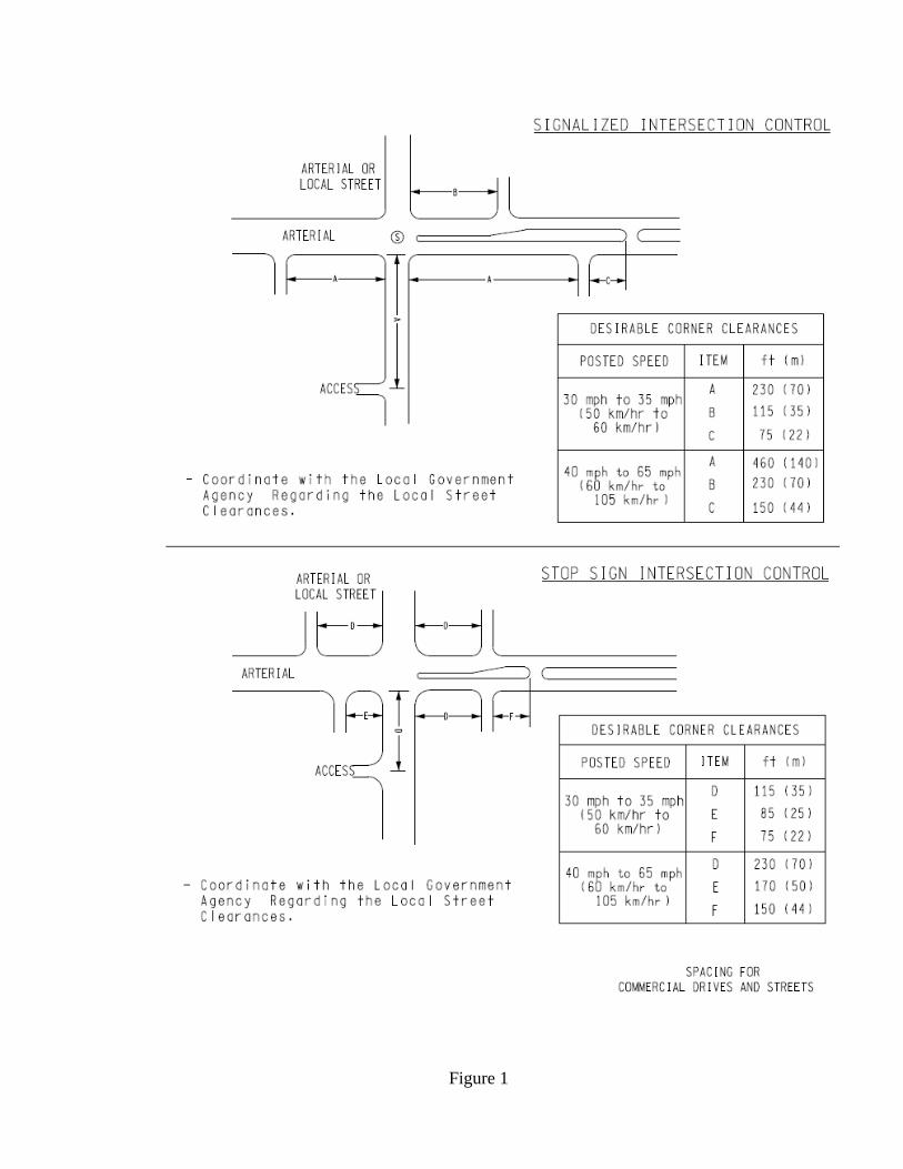
Figure 1

Figure 2
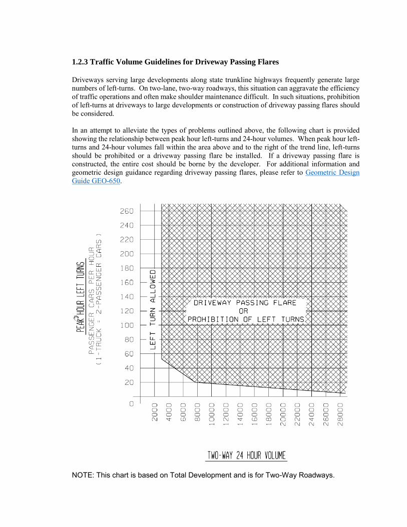
1.2.3 Traffic Volume Guidelines for Driveway Passing Flares
Driveways serving large developments along state trunkline highways frequently generate large numbers of left-turns. On two-lane, two-way roadways, this situation can aggravate the efficiency of traffic operations and often make shoulder maintenance difficult. In such situations, prohibition of left-turns at driveways to large developments or construction of driveway passing flares should be considered. In an attempt to alleviate the types of problems outlined above, the following chart is provided showing the relationship between peak hour left-turns and 24-hour volumes. When peak hour left-turns and 24-hour volumes fall within the area above and to the right of the trend line, left-turns should be prohibited or a driveway passing flare be installed. If a driveway passing flare is constructed, the entire cost should be borne by the developer. For additional information and geometric design guidance regarding driveway passing flares, please refer to Geometric Design Guide GEO-650.
NOTE: This chart is based on Total Development and is for Two-Way Roadways.
1.2.4 Traffic Impact Studies
A traffic impact study is a complete analysis and assessment of traffic generated by a proposed development and of the impact a proposed development would have on the surrounding transportation system. A traffic impact study is required for any proposed development expected to generate over one hundred (100) peak hour directional trips or at the discretion of the Region/TSC Traffic and Safety Engineer. The study shall be completed and sealed by a licensed professional engineer. The consulting firm shall be pre-qualified by MDOT to do Traffic Capacity Analysis and Geometric Studies. If the study includes the review of potential signal operations, a pre-qualified Traffic Signal Operations consultant must be used. Lansing Traffic and Safety, as well as the Region, should review these studies. The table at the end of this section gives examples of land uses that are expected to meet or exceed the 100 peak hour directional trip threshold. Region Review: 1. The Region/TSC Utilities and Permits Section reviews all proposed access plans,
and then forwards the plans to the Region Traffic and Safety Engineer with their recommendations. Region Traffic and Safety will notify the Utilities and Permits Engineer if a traffic impact study is required from the developer before the access permit can be issued.
2. The Utilities and Permits Engineer will inform the developer of the required impact
study. 3. If an access management corridor team has been established in the vicinity of said
development, the draft impact study will be submitted to the corridor team for advisory input prior to awarding a MDOT permit.
A traffic impact study should include: 1. A disclaimer which indicates that the opinions, findings, and conclusions expressed
in this TIA are those of the authors and not necessarily those of the MDOT. 2. A narrative summary at the beginning of the report, including, but not limited to:
a. The applicant and project name. b. A location map with dimensions with references to state trunklines. c. The size and type of development. d. Generated traffic volumes based on type and size of land use which are
compatible with those listed in the Institute of Transportation Engineers (ITE) publication, Trip Generation (current edition).
e. A disclaimer indicating why the TIA is being completed. f. A location for MDOT (Lansing Traffic and Safety and the Region) to indicate
they reviewed the TIA and accept/reject the assessment.
3. Project phasing identifying the year of development activities per phase and proposed access plan for each phase.
4. A transportation system inventory, which describes the physical, functional and
operational characteristics of the study area highway system and, where pertinent, local transit services. The description should provide, where applicable, data regarding:
a. Peak-hour volumes for individual traffic movements (existing and projected)
(The growth rates used for traffic volume projections should come from the Urban
Travel Demand Model or the Statewide Model. If not, the annual growth rate
selected for use shall be subject to approval by MDOT staff).
b. Number of lanes c. Cross-section d. Intersection traffic signals and configuration e. Traffic signal progression f. Percentage of heavy trucks g. Adjacent access point locations h. Jurisdiction i. Grades
5. A plan showing proposed roadway per phase for each access. The plan needs to be
in scale and show lane configurations, drives, traffic signals, and other geometric information pertinent to the study. Driveway design and roadway improvements shall meet Michigan Department of Transportation standards and guides.
6. A capacity analysis shall be performed at each access point. The Department
software preference is Synchro. Default values shall not be used when actual values are reasonably available or obtainable. Every effort should be made to obtain accurate values, or good, justifiable estimates. The interaction of conflicting traffic movements shall be addressed in the traffic impact study. Any proposed signalized access point within 1 mile (1.6 km) of an existing signalized intersection shall be analyzed in coordination with the existing signal timing along the entire signalized corridor. A time-space diagram should also be included.
7. A traffic impact study on the trunkline shall be analyzed with and without the
proposed development on the existing system, and with the proposed development for both existing and projected traffic volumes. The growth rates used for traffic volume projections should come from the Urban Travel Demand Model or the Statewide Model. If not, the annual growth rate selected for use shall be subject to approval by MDOT staff).
The traffic volumes for the development shall assume a total build out. If desired, the traffic volumes generated by each individual phase may be provided as well.
If the development generates 500 or more trips in the peak hour, then a minimum
5-year horizon forecast must be included. This means total traffic (background + development) forecasted at least 5 years beyond opening year.
o 500 peak hour trips (In+Out) after reductions for by-pass trips o If development has an opening day and a future buildout, then the future
buildout can serve as the 5 year horizon forecast (only if the future buildout is at least 5 years after opening day)
If the development is at or near a major intersection or interchange, then traffic
generated for the site should also be shown relative to movements into and/or through the intersection or interchange. Large developments should indicate expected market area such as a shopping mall.
The completed traffic analysis shall be summarized in a table showing all the Measures of Effectiveness (MOE’s) for each individual traffic movement for all the above conditions.
8. Required operational changes and/or other mitigation measures shall be part of the permit approval process.
9. The consultant and the Department should strive to reach an agreement on the
assumptions and methodology of the traffic impact study. In areas where an agreement cannot be reached, the Department may provide a response to the traffic impact study that will be made part of the final study and included in the appendix.
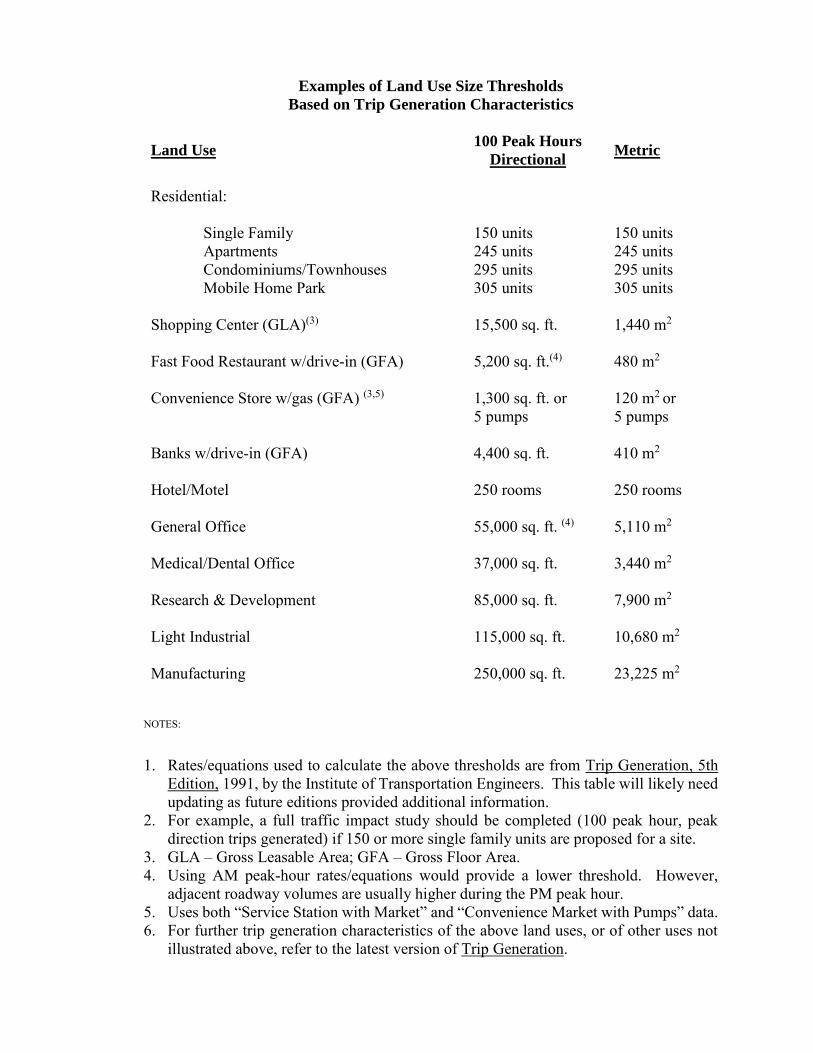
Examples of Land Use Size Thresholds
Based on Trip Generation Characteristics
Land Use 100 Peak Hours
Directional Metric
Residential:
Single Family 150 units 150 units
Apartments 245 units 245 units Condominiums/Townhouses 295 units 295 units Mobile Home Park 305 units 305 units Shopping Center (GLA)(3) 15,500 sq. ft. 1,440 m2 Fast Food Restaurant w/drive-in (GFA) 5,200 sq. ft.(4) 480 m2 Convenience Store w/gas (GFA) (3,5) 1,300 sq. ft. or
5 pumps 120 m2 or 5 pumps
Banks w/drive-in (GFA) 4,400 sq. ft. 410 m2
Hotel/Motel 250 rooms 250 rooms General Office 55,000 sq. ft. (4) 5,110 m2 Medical/Dental Office 37,000 sq. ft. 3,440 m2 Research & Development 85,000 sq. ft. 7,900 m2 Light Industrial 115,000 sq. ft. 10,680 m2 Manufacturing 250,000 sq. ft. 23,225 m2
NOTES:
1. Rates/equations used to calculate the above thresholds are from Trip Generation, 5th Edition, 1991, by the Institute of Transportation Engineers. This table will likely need updating as future editions provided additional information.
2. For example, a full traffic impact study should be completed (100 peak hour, peak direction trips generated) if 150 or more single family units are proposed for a site.
3. GLA – Gross Leasable Area; GFA – Gross Floor Area. 4. Using AM peak-hour rates/equations would provide a lower threshold. However,
adjacent roadway volumes are usually higher during the PM peak hour. 5. Uses both “Service Station with Market” and “Convenience Market with Pumps” data. 6. For further trip generation characteristics of the above land uses, or of other uses not
illustrated above, refer to the latest version of Trip Generation.
1.2.5 Traffic Impact Assessments
A traffic impact assessment is completed for uses which generate a relatively low volume of traffic.
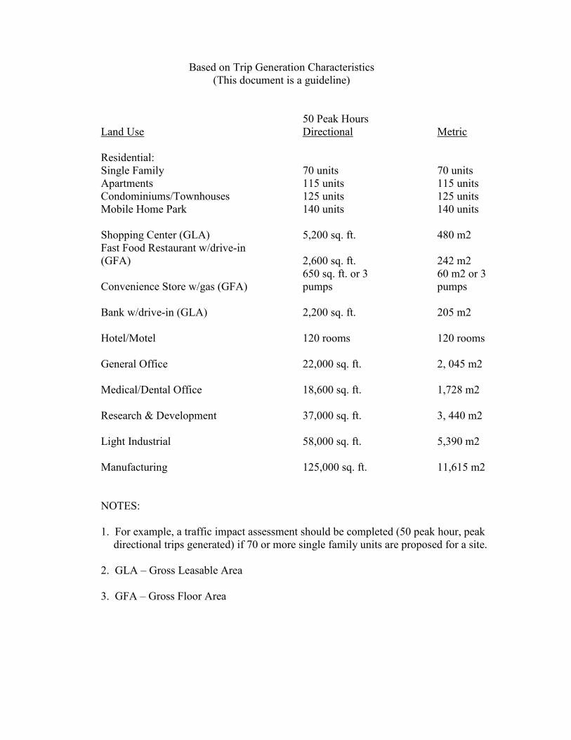
A traffic impact assessment is required for any proposed development expected to generate between fifty (50) and ninety-nine (99) peak hour directional trips, or at the discretion of the Region/TSC Traffic & Safety Engineer. The table at the end of this section gives examples of land uses that are expected to meet or exceed the fifty (50) peak hour directional trip threshold. A traffic impact study (as outlined in Section 1.2.4) shall be required for any proposed development expected to generate over ninety-nine (99) peak hour directional trips, or if requested by the Region/TSC Traffic & Safety Engineer. Lansing Traffic and Safety, as well as the Region, may review these studies.
The Traffic Impact Assessment should include:
1. A narrative summary at the beginning of the report, including, but not limited to:
a. The applicant and project name. b. A location map with dimensions including proposed drives and distances
and/or references to state trunklines. c. The size and type of development.
2. Generated traffic volumes based on the type and size of land use which are compatible with those listed in the Institute of Transportations Engineers (ITE) publication Trip Generation (current edition). They should be in the area of the proposed site drives. The traffic volumes for the development shall assume a total build out. Both the peak hour trip generation and the daily trip generation should be used. Local or specific development data can be used, if available, only at the discretion of the Region/TSC Traffic Engineer. Developers can use their own data in the collection of estimated traffic generated. The use of secondary data outside of the ITE Trip Generation Manual is acceptable as long as the business that is being referenced is comparable in type and size to the proposed development and the state trunkline and local primary connectors have similar ADT. The ITE Trip Generation Manual has small sample sizes for several types of developments, and may not be the best source of information for data collection purposes.
3. Existing Traffic Volumes – Volumes during peak hours adjacent to the site. 4. Project phasing identifying the year of development activities per phase and the
proposed access plan for each phase.
5. Trip Distribution/Assignment for the proposed drives. Trip distribution/assignment is for the peak hours (assuming morning and evening). Weekend peak hour data may be requested by the Region/TSC Traffic Engineer if applicable.
6. Access: Identify the location of any existing drives within approximately 450 feet
(140 m) of the site. Identify the location of the proposed drives. A proposed driveway spacing based on a 50 MPH (80 Km/h) posted speed is suggested, if feasible. Please refer to Section 1.2.2 for additional guidance regarding the spacing of commercial driveways.
If it is determined that the impacts of the development affect areas beyond the proposed drives, additional information or assessment may be requested. If there are any existing corridor groups studying or managing the area of the proposed development, coordination with these groups will be needed regarding the proposed project. A corridor group can be defined as a transportation planning group consisting of local officials, MDOT staff, and various other key stakeholders interested in preserving and/or improving the safety, capacity, economic sustainability, and aesthetics of a particular transportation corridor.
Examples of Land Use Size Thresholds
Based on Trip Generation Characteristics (This document is a guideline)
50 Peak Hours Land Use Directional Metric Residential: Single Family 70 units 70 units Apartments 115 units 115 units Condominiums/Townhouses 125 units 125 units Mobile Home Park 140 units 140 units Shopping Center (GLA) 5,200 sq. ft. 480 m2 Fast Food Restaurant w/drive-in (GFA) 2,600 sq. ft. 242 m2 650 sq. ft. or 3 60 m2 or 3 Convenience Store w/gas (GFA) pumps pumps Bank w/drive-in (GLA) 2,200 sq. ft. 205 m2 Hotel/Motel 120 rooms 120 rooms General Office 22,000 sq. ft. 2, 045 m2 Medical/Dental Office 18,600 sq. ft. 1,728 m2 Research & Development 37,000 sq. ft. 3, 440 m2 Light Industrial 58,000 sq. ft. 5,390 m2 Manufacturing 125,000 sq. ft. 11,615 m2 NOTES: 1. For example, a traffic impact assessment should be completed (50 peak hour, peak
directional trips generated) if 70 or more single family units are proposed for a site. 2. GLA – Gross Leasable Area 3. GFA – Gross Floor Area
1.2.6 Truck Route Classification Considerations
Traffic and Safety has the responsibility of evaluating trunklines for operational, safety, and traffic considerations. The following factors should be considered when evaluating the addition of routes to the Special Designated System (Green Routes) as shown on the current TRUCK OPERATOR’S MAP. This map is available online.
1. Safety Record of the Roadway. Crashes should be evaluated and the crash rate of the roadway section should be compared to the region and statewide crash rates.
2. Site Review for Safety Concerns. The sufficiency report should be reviewed for roadway condition and percentage of no passing zones.
3. Alternate Routes. The availability of an alternate route may preclude addition of a
proposed roadway section.
4. Existing Cross-sections. The current lane widths should be reviewed to determine if geometric improvements are needed. Generally, paved shoulder ribbons are added to 11 foot (3.3 m) and 12 foot (3.6 m) lanes, while 10 foot (3.0 m) lanes may be precluded from the system.
5. Sight Distance. “No Passing Zones” should not exceed 40 percent of the section of route being considered for reclassification. If feasible, the level of service should be used as determining criteria.
6. Severity and Lengths of Grade. The addition of climbing lanes may be necessary with the addition of large vehicles.
7. Shoulder widths. Shoulder widths should be as recommended by AASHTO, with the
possible inclusion of paved shoulders.
8. Review Bridges. Review bridges underclearances and bridge widths on the proposed truck route.
9. Turning Radii. Review the intersection radii to see if trucks can be accommodated.
Intersection widening may be needed to accommodate truck movements.
2.0 SAFETY CONSIDERATIONS
The following are related primarily to traffic safety issues. The sections are divided into two types of treatments: Intersection Treatments and Corridor/Midblock Treatments. It should be noted that while this guidance typically pertains to traffic safety issues, many of these treatments provide tangible improvements to traffic operations as well as increased traffic safety benefits. 2.0 Safety Considerations
2.1 Intersection Treatments 2.1.1 Traffic Volume Guidelines for Right-Turn Lanes and Tapers 2.1.2 Traffic Volume Guidelines for Left-Turn Lanes and Passing Flares 2.1.3 Clear Vision Areas 2.1.4 Roundabouts
2.2 Corridor/Midblock Treatments 2.2.1 Roadside Traffic Control Islands 2.2.2 Traffic Volume Guidelines for Driveway Passing Flares 2.2.3 On-Street Angled Parking
2.1.1 Traffic Volume Guidelines for Right-Turn Lanes and Tapers
See Section 1.1.4. 2.1.2 Traffic Volume Guidelines for Left-Turn Lanes and Passing Flares at
Unsignalized Intersections
See Section 1.1.5. 2.1.3 Clear Vision Areas
See Section 1.1.3. 2.1.4 Roundabouts
See Section 1.1.7. 2.2.1 Roadside Traffic Control Islands
See Section 1.2.1 2.2.2 Traffic Volume Guidelines for Driveway Passing Flares
See Section 1.2.3.
2.2.3 On-Street Angled Parking Pull-in angled parking will not be permitted on state trunkline. Only back-in angled parking will be considered. In some downtown areas, a parallel parking configuration does not adequately meet the demand for parking spaces or is limited by other operational issues. In these areas, the use of back-in angled parking can increase parking capacity or more appropriately address site constraints. In order to consider the use of back-in angled parking over parallel parking, the following criteria shall be considered and documented by the local government agency:
- A capacity analysis shall be performed, demonstrating that future peak hour traffic conditions under the proposed cross section will operate at an acceptable level of service with the addition of back-in angled parking (e.g. LOS D or better in urban areas and LOS C or better in rural areas).
- The vehicle overhang at the curb shall not reduce the pedestrian walkway effective width
to less than 5 feet or in any way impede Americans with Disability Act (ADA) accessibility.
- Parking spaces shall not exist within Intersection Sight Distance triangles.
- All geometric elements of the proposed cross section shall meet department standards.
The following additional criteria should be considered:
- An adequate clear area should be provided behind the face of curb to allow for vehicle overhang. Fixed object placement and maintenance in this area are critical concerns.
- Existing auxiliary lanes (i.e. Turn lanes at intersections) should be preserved.
- The proposed cross-section with back-in angled parking should be able to accommodate
an existing or planned bike lane as defined in the community’s non-motorized plan in support of the department’s complete streets policy.
The implementation of back-in angled parking requires approval of Michigan Department of Transportation (MDOT) Engineering Operations Committee (EOC). A formal resolution from the city/village/township council or board must be provided to MDOT in support of the request. A template resolution which can be used by city/village/township council or board is at the end of this section. The last paragraph of this template resolution beginning, “Now, Therefore be it Resolved, . . .” must be included before MDOT will consider a study for back-in angled parking on the requested route. The city/village/township will be responsible for the study To accommodate back-in angled parking a reduction in the number of through lane on the requested route may be required. The city/village/township will be responsible for this
evaluation. If a lane reduction or Road Diet is required to accommodate back-in angled parking then a traffic engineering study must be performed and included in the study for back-in angled parking. The traffic engineering study must be performed by a MDOT pre-qualified Traffic Capacity Analysis & Geometric Studies consultant. MDOT reserves the right to evaluate any trunkline corridor with back-in angled parking that exhibits operational and/or safety concerns to determine if the type of parking is having any impacts detrimental to the corridor. If such concerns are documented, MDOT will take corrective actions that may include the restoration of prior parking configurations.
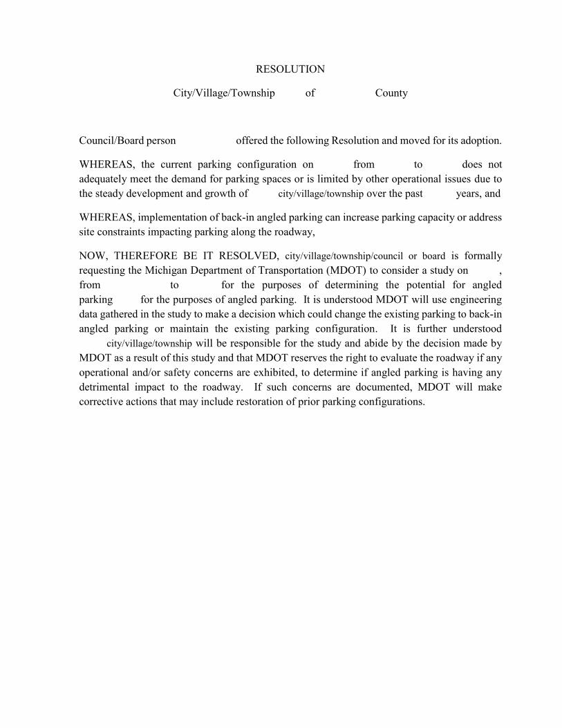
RESOLUTION
City/Village/Township of County
Council/Board person offered the following Resolution and moved for its adoption.
WHEREAS, the current parking configuration on from to does not adequately meet the demand for parking spaces or is limited by other operational issues due to the steady development and growth of city/village/township over the past years, and
WHEREAS, implementation of back-in angled parking can increase parking capacity or address site constraints impacting parking along the roadway,
NOW, THEREFORE BE IT RESOLVED, city/village/township/council or board is formally requesting the Michigan Department of Transportation (MDOT) to consider a study on , from to for the purposes of determining the potential for angled parking for the purposes of angled parking. It is understood MDOT will use engineering data gathered in the study to make a decision which could change the existing parking to back-in angled parking or maintain the existing parking configuration. It is further understood city/village/township will be responsible for the study and abide by the decision made by MDOT as a result of this study and that MDOT reserves the right to evaluate the roadway if any operational and/or safety concerns are exhibited, to determine if angled parking is having any detrimental impact to the roadway. If such concerns are documented, MDOT will make corrective actions that may include restoration of prior parking configurations.
3.0 MISCELLANEOUS CONSIDERATIONS
The following provide guidance relating to a variety of miscellaneous traffic issues. The sections are divided into three categories: Parking, Studies and Analyses, and Lighting. 3.0 Miscellaneous Considerations
3.1 Parking 3.1.1 On-Street Angled Parking 3.1.2 Parking Facility Dimensions
3.2 Studies and Analyses 3.2.1 Design Exception Request Crash Analysis 3.2.2 Truck Route Classification Considerations 3.2.3 Traffic Impact Studies 3.2.4 Traffic Impact Assessments
3.3 Lighting
3.3.1 Non-Freeway Lighting 3.3.2 Freeway Lighting 3.3.3 Illumination at Railroad Crossings

3.1.1 On-Street Angled Parking See Section 2.2.3.
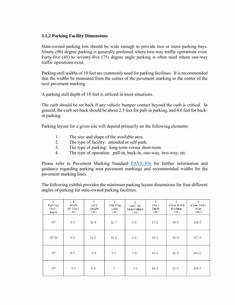
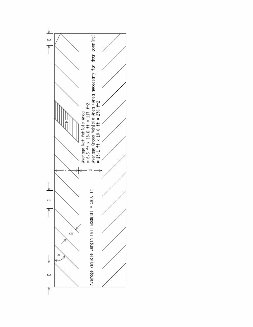
3.1.2 Parking Facility Dimensions
State-owned parking lots should be wide enough to provide two or more parking bays. Ninety (90) degree parking is generally preferred where two-way traffic operations exist. Forty-five (45) to seventy-five (75) degree angle parking is often used where one-way traffic operations exist. Parking stall widths of 10 feet are commonly used for parking facilities. It is recommended that the widths be measured from the center of the pavement marking to the center of the next pavement marking. A parking stall depth of 18 feet is utilized in most situations. The curb should be set back if any vehicle bumper contact beyond the curb is critical. In general, the curb set-back should be about 2.5 feet for pull-in parking, and 4.0 feet for back-in parking. Parking layout for a given site will depend primarily on the following elements: 1. The size and shape of the available area. 2. The type of facility: attended or self-park. 3. The type of parking: long-term versus short-term. 4. The type of operation: pull-in, back-in, one-way, two-way, etc. Please refer to Pavement Marking Standard PAVE-956 for further information and guidance regarding parking area pavement markings and recommended widths for the pavement marking lines. The following exhibit provides the minimum parking layout dimensions for four different angles of parking for state-owned parking facilities.

3.2.1 Design Exception/Variance
A safety review is required for all 3R and 4R projects. The Project Manager should contact
the TSC Traffic Engineer during scoping, so that a safety review can be performed
throughout the project limits. On corridor projects only one analysis that includes roadways
and bridges is required. This review should consist of an analysis of available crash data to
determine where safety enhancements are warranted. Safety reviews more than three years
old shall be updated to verify the original safety review.
A site-specific crash analysis is required as justification for any design exception or design
variance. It is also required in determining appropriate 3R design criteria according to
Section 3.09.02A and 3.09.02B of the Road Design Manual. Site specific crash analyses
more than three years old shall be updated to verify the original crash analysis.
During the review process the Geometric Design Unit will review plans and identify the
need for Design Exceptions (DE) or Design Variances (DV) when standards are not met
for specified geometric design elements. These elements are listed below with their
corresponding level of documentation and/or approval. For more information on design
exceptions/variances go to Section 3.08.01E of the Road Design Manual.
For information on how to complete the crash analysis for a design exception/variance see
Chapter 2 of the Safety Programs Manual, Design Exception/Variance Request Crash
Analysis.
Non-Standard Design Element (NHS and Non-NHS) (See
Section 3.11.01 for DE Criteria for 3R freeway work)
Applicability of Design Exception
(DE) Design Variance (DV)
Design Speed
≥ 50 MPH < 50 MPH
Design Speed < Posted Speed DE DE
Lane Width* DE DV
Shoulder Width DE DV
Horizontal Curve Radius* DE DV
Superelevation Rate* DE DV
Superelevation Transition* DV DV
Maximum Grade* DE DV
Stopping Sight Distance
(Horizontal and Vertical)*
DE
DV
Cross Slope DE DV
Vertical Clearance DE DE
Design Loading Structural Capacity DE DE
Ramp Acceleration / Deceleration Length* DV DV
*Values based on design speeds less than posted.
3.2.2 Truck Route Classification Considerations
See Section 1.2.6. 3.2.3 Traffic Impact Studies
See Section 1.2.4. 3.2.4 Traffic Impact Assessments
See Section 1.2.5. .
3.3.1 Non-Freeway Lighting
Local governmental agencies are responsible for the installation, operation, and maintenance of lighting on non-freeway state trunklines. When a local agency requests a permit from the Region Utilities-Permits Engineer to install or upgrade lighting on a trunkline, the Region/TSC Representative should review the plans for such work to ensure that light standards and utility poles are located so as to provide a safe recovery area for motorists. Matters relating to illumination levels may be referred to the Municipal Utilities Design Unit in the Design Division. Please refer to the Michigan Road Design Manual, Chapter 9 for additional guidance regarding the placement of lighting standards and utility poles and in the latest edition of the AASHTO Roadway Lighting Design Guide.
3.3.2 Freeway Lighting
Freeway lighting facilities may be provided under the following conditions:
1. If a proposed project meets the warrants for either continuous freeway lighting,
interchange lighting on unlighted freeways, or lighting for freeway bridges,
overpasses and underpasses, as discussed in the AASHTO Roadway Lighting
Design Guide, the project shall be reviewed by the department to determine the
extent of lighting to be furnished. For interchange lighting refer to the Interchange
Lighting Guidance Document (10235).
2. Freeway lighting will be provided only if it enhances highway safety as determined
by the Region/TSC analysis. The design of the system shall be such that it
contributes to the overall safety of the freeway.
3. Continuous freeway lighting and full interchange lighting should be designed in
accordance with the AASHTO publication noted above.
4. Isolated interchange lighting shall be designed for a maintained average
illumination of 1.0 foot candles (10.75 lux) maximum.
5. Partial interchange lighting may be considered for any interchange.
6. Freeway lighting standards shall not be used in urban freeway medians unless they
are installed on the top of the concrete median barriers. Ordinarily, lighting
standards are located on the perimeter of the roadway.
7. The Electrical Design Unit in Lansing Design will review all designs of freeway
lighting facilities and coordinate with other involved support areas.
Freeway lighting exceeding that which the department has approved for traffic safety
purposes may be furnished and maintained at the expense of the local governmental
agency. Such lighting must be in accordance with department specifications and approved
by permit.
Please refer to the Michigan Road Design Manual, Chapter 9 for additional guidance
regarding the placement of lighting standards and utility poles and in the latest edition of
the AASHTO Roadway Lighting Design Guide.
3.3.3 Illumination at Railroad Crossings
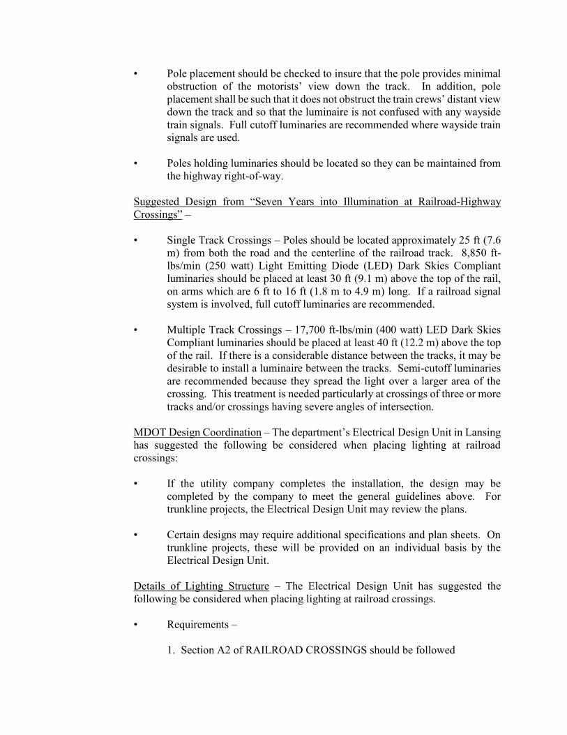
This guideline was developed to assist in the placement of lighting at railroad at-grade crossings. In general, the lighting should illuminate passive and/or active warning devices, the pavement surface and markings, and the presence or absence of a train in or approaching the crossing. The luminaries should be aligned toward the railroad tracks instead of the roadway. The figure on page 2 shows a recommended lighting configuration.
General Guidelines - The first three guidelines are being adopted from an article entitled “Seven Years into Illumination at Railroad-Highway Crossings” by Richard A. Mather, Crossing Signal Specialist for the Oregon Public Utility Commission. • At least one luminaire shall be mounted on each side of the track at the
crossing. Luminaires should be located so that warning devices at the crossing will be directly illuminated.
• Luminaires shall be oriented toward the railroad track to provide at least 1
ft candle (11 lux) of illumination on the vertical plane 5 ft (1.5 m) from the centerline of track. (Maximum permissible level of illumination and exact orientation of the luminaire will be determined on a case-by-case basis. Factors at the site, including the ambient level of nighttime illumination, need to be considered.) [Note: The maximum level of illumination is related to the level of lighting on the roadway approaches. The level of illumination should be sufficient to alert drivers to the crossing ahead and to any railroad equipment occupying the crossing, but should not be so bright as to create a “blinding” effect for motorists in the area immediately beyond the crossing. Cutoffs will normally be used on luminaries to minimize this “blinding” effect.]
• Luminaries should illuminate an area along the track which is 50 percent
wider than the traveled width of the road. For example, if the road is 20 ft (6.1 m) in width, the roadway width plus 5 ft (1.5 m) along the track on each side of the road should be illuminated. If the roadway is less than 20 ft (6.1 m) in width, a minimum illumination of 5 ft (1.5 m) down the track should be maintained. The illumination should cover a distance which is equal to the normal height of rail equipment [at least 15 ft (4.6 m) above the top of the rail].
• Section 9.03 of the department’s Road Design Manual discusses the
placement of light standards. • Poles should be placed a minimum of 9.0 ft (2.7 m) from the center line of
the track to maintain track clearance requirements.
• Pole placement should be checked to insure that the pole provides minimal obstruction of the motorists’ view down the track. In addition, pole placement shall be such that it does not obstruct the train crews’ distant view down the track and so that the luminaire is not confused with any wayside train signals. Full cutoff luminaries are recommended where wayside train signals are used.
• Poles holding luminaries should be located so they can be maintained from
the highway right-of-way.
Suggested Design from “Seven Years into Illumination at Railroad-Highway Crossings” –
• Single Track Crossings – Poles should be located approximately 25 ft (7.6
m) from both the road and the centerline of the railroad track. 8,850 ft-lbs/min (250 watt) Light Emitting Diode (LED) Dark Skies Compliant luminaries should be placed at least 30 ft (9.1 m) above the top of the rail, on arms which are 6 ft to 16 ft (1.8 m to 4.9 m) long. If a railroad signal system is involved, full cutoff luminaries are recommended.
• Multiple Track Crossings – 17,700 ft-lbs/min (400 watt) LED Dark Skies
Compliant luminaries should be placed at least 40 ft (12.2 m) above the top of the rail. If there is a considerable distance between the tracks, it may be desirable to install a luminaire between the tracks. Semi-cutoff luminaries are recommended because they spread the light over a larger area of the crossing. This treatment is needed particularly at crossings of three or more tracks and/or crossings having severe angles of intersection.
MDOT Design Coordination – The department’s Electrical Design Unit in Lansing has suggested the following be considered when placing lighting at railroad crossings:
• If the utility company completes the installation, the design may be
completed by the company to meet the general guidelines above. For trunkline projects, the Electrical Design Unit may review the plans.
• Certain designs may require additional specifications and plan sheets. On
trunkline projects, these will be provided on an individual basis by the Electrical Design Unit.
Details of Lighting Structure – The Electrical Design Unit has suggested the
following be considered when placing lighting at railroad crossings. • Requirements – 1. Section A2 of RAILROAD CROSSINGS should be followed
2. 11,063 ft-lbs/min (250 watt) LED Dark Skies Compliant luminaire 3. 35 ft (10.7 m) mounting height 4. Photocell on lights • Considerations –
1. Source of payment for the energy needs to be worked out between the
local government and the utility company/Railroad/Road Authority. 2. If the utility company does the installation, all they need are the basics
and they will finish the design. The Electrical Design Unit can check their plans.
3. Certain designs may require additional specifications and plan sheets
provided on an individual basis by the Electrical Design Unit. Installation – The cost of installation may be paid for by the Governmental and Railroad Coordination Section of Lansing Design. Costs for future electricity may be paid for by Region/TSC maintenance. Cost details should be worked out before the lighting is installed. Maintenance –
• According to Mather, in 1990, the average monthly maintenance cost per luminaire/pole was $15. This includes electricity and maintenance activities. This cost was for lights that the road authority took ownership of after installation. Public owned utilities were slightly less.
• Source of payment for the energy should be arranged between the involved
parties.
REFERENCES: Mather, Richard A., Crossing Signal Specialist for the Oregon Public Utility Commission, “Seven Years into Illumination at Railroad-Highway Crossings”, June 1990. Michigan Department of Transportation, Road Design Manual, Section 9.03. “Roadway Lighting” RP-8, American National Standard, IES (Illuminating Engineering Society).
![Fast exact parallel 3D mesh intersection algorithm using ...PostGIS to perform exact geometric computation. Bernstein and Fussell [4] also presented an intersection algo-rithm that](https://static.fdocuments.us/doc/165x107/5e8f60180438702de559ff8e/fast-exact-parallel-3d-mesh-intersection-algorithm-using-postgis-to-perform.jpg)


![arXiv:1612.03638v1 [cs.DM] 12 Dec 2016 · linear structure of bacterial genes by Benzer in 1959 [1]. We consider geometric intersection graphs, that is, intersection graphs of simple](https://static.fdocuments.us/doc/165x107/6087b33f957e3b36386dffe3/arxiv161203638v1-csdm-12-dec-2016-linear-structure-of-bacterial-genes-by-benzer.jpg)


