Gentle synchronization of two-speed synchronous motor with ... · Electr Eng (2012) 94:155–163...
9
Electr Eng (2012) 94:155–163 DOI 10.1007/s00202-011-0227-1 ORIGINAL PAPER Gentle synchronization of two-speed synchronous motor with asynchronous starting Pawel Zalas · Jan Zawilak Received: 5 November 2009 / Accepted: 20 November 2011 / Published online: 9 December 2011 © The Author(s) 2011. This article is published with open access at Springerlink.com Abstract The paper presents the results of synchroniza- tion calculations for a selected model of the GAe 1716/20t two-speed synchronous motor with switchable armature and field magnet windings, used for driving the main fans in deep mines. The calculations were performed using a spe- cially developed (and validated by measurements) field-cir- cuit model of the motor. The effect of the initial instant of synchronization on the latter’s effectiveness and on dynamic process stabilization time was studied. It is shown that syn- chronization effectiveness can be increased through proper field current control in the synchronization initiation–syn- chronous speed interval. It is also shown that synchronization time can be reduced and the dynamic waveforms attenuated after the motor reaches the synchronous speed. The calcula- tion results are presented in the form of diagrams. Keywords Electrotechnology · Synchronous motors · Synchronization process · FEM modelling 1 Introduction Electromagnetically excited large-power salient-pole syn- chronous motors are commonly employed in the drive sys- tems of the main-ventilation fans in deep mines. Considering their number and installed capacity, they make up a group of the largest electric energy consumers in the mine. Big sav- ings can be made and the total mining costs can be reduced P. Zalas (B ) Institute of Electrical Machines, Drives and Metrology, Wroclaw University of Technology, ul. Smoluchowskiego 19, 50-372 Wroclaw, Poland e-mail: [email protected] J. Zawilak e-mail: [email protected] through the rational use of the fans’ capacity. The biggest savings in electric energy can be achieved by changing the rotational speed of the driving machine [1]. The speed of the synchronous motor can be controlled by changing the amplitude and frequency of the supply voltage. But the appli- cation of large-power electronic frequency converters still entails high capital costs. The required fan capacity control can also be obtained through the use of two-speed synchro- nous motors in which a change of speed is effected by chang- ing the number of motor magnetic field poles. Because of the costs, the existing single-speed motors (their magnetic core and mechanical structure) are upgraded for this purpose. The upgrading consists in using a switchable stator winding and rotor winding switching through an additional pair of slip rings [12]. By changing the direction of currents in appropri- ate groups of stator windings and the polarity of appropriate field-magnet poles, one can obtain another, larger, number of resultant magnetic-field poles and so another, lower, rota- tional motor speed. The upgrading is cheaper than the use of large-power converter systems and the stepwise change of speed ensures sufficient capacity control and results in a significant reduc- tion of the power consumed by the fan. One of the motors upgraded in this way is a two-speed synchronous motor of type GAe 1716/20t. Its main specifications and the specifi- cation of the single-speed motor are presented in Table 1. By lowering the rotational speed from 375 to 300 rpm, one can reduce the motor’s power by over 50% and so consider- ably reduce the annual energy consumption [4], which will compensate for the upgrading costs. Since the motors have a salient-pole rotor, then at the two- speed motor’s lower speed the number of mechanical poles is different than the number of magnetic poles (respectively, 16 and 20). Due to the fact that the number of magnetic poles is different from that of mechanical poles, the particular poles 123
-
Upload
duongnguyet -
Category
Documents
-
view
216 -
download
0
Transcript of Gentle synchronization of two-speed synchronous motor with ... · Electr Eng (2012) 94:155–163...
Electr Eng (2012) 94:155–163DOI 10.1007/s00202-011-0227-1
ORIGINAL PAPER
Gentle synchronization of two-speed synchronous motorwith asynchronous starting
Paweł Zalas · Jan Zawilak
Received: 5 November 2009 / Accepted: 20 November 2011 / Published online: 9 December 2011© The Author(s) 2011. This article is published with open access at Springerlink.com
Abstract The paper presents the results of synchroniza-tion calculations for a selected model of the GAe 1716/20ttwo-speed synchronous motor with switchable armature andfield magnet windings, used for driving the main fans indeep mines. The calculations were performed using a spe-cially developed (and validated by measurements) field-cir-cuit model of the motor. The effect of the initial instant ofsynchronization on the latter’s effectiveness and on dynamicprocess stabilization time was studied. It is shown that syn-chronization effectiveness can be increased through properfield current control in the synchronization initiation–syn-chronous speed interval. It is also shown that synchronizationtime can be reduced and the dynamic waveforms attenuatedafter the motor reaches the synchronous speed. The calcula-tion results are presented in the form of diagrams.
Keywords Electrotechnology · Synchronous motors ·Synchronization process · FEM modelling
1 Introduction
Electromagnetically excited large-power salient-pole syn-chronous motors are commonly employed in the drive sys-tems of the main-ventilation fans in deep mines. Consideringtheir number and installed capacity, they make up a group ofthe largest electric energy consumers in the mine. Big sav-ings can be made and the total mining costs can be reduced
P. Zalas (B)Institute of Electrical Machines, Drives and Metrology,Wroclaw University of Technology, ul. Smoluchowskiego 19,50-372 Wroclaw, Polande-mail: [email protected]
J. Zawilake-mail: [email protected]
through the rational use of the fans’ capacity. The biggestsavings in electric energy can be achieved by changing therotational speed of the driving machine [1]. The speed ofthe synchronous motor can be controlled by changing theamplitude and frequency of the supply voltage. But the appli-cation of large-power electronic frequency converters stillentails high capital costs. The required fan capacity controlcan also be obtained through the use of two-speed synchro-nous motors in which a change of speed is effected by chang-ing the number of motor magnetic field poles. Because of thecosts, the existing single-speed motors (their magnetic coreand mechanical structure) are upgraded for this purpose. Theupgrading consists in using a switchable stator winding androtor winding switching through an additional pair of sliprings [12]. By changing the direction of currents in appropri-ate groups of stator windings and the polarity of appropriatefield-magnet poles, one can obtain another, larger, numberof resultant magnetic-field poles and so another, lower, rota-tional motor speed.
The upgrading is cheaper than the use of large-powerconverter systems and the stepwise change of speed ensuressufficient capacity control and results in a significant reduc-tion of the power consumed by the fan. One of the motorsupgraded in this way is a two-speed synchronous motor oftype GAe 1716/20t. Its main specifications and the specifi-cation of the single-speed motor are presented in Table 1.By lowering the rotational speed from 375 to 300 rpm, onecan reduce the motor’s power by over 50% and so consider-ably reduce the annual energy consumption [4], which willcompensate for the upgrading costs.
Since the motors have a salient-pole rotor, then at the two-speed motor’s lower speed the number of mechanical poles isdifferent than the number of magnetic poles (respectively, 16and 20). Due to the fact that the number of magnetic poles isdifferent from that of mechanical poles, the particular poles
123
156 Electr Eng (2012) 94:155–163
Table 1 The ratings of two-speed synchronous motor GAe 1716/20tand single-speed motor GAe 1716t
Motor type (GAe) 1716t 1716/20t
Rated power (MW) 3.15 2.6 1.2
Stator voltage (kV) 6 6 6
Stator current (A) 350 292 186
Field voltage (V) 90 100 78
Field current (A) 350 337 260
Rotational speed (rpm) 375 375 300
Power factor 0.9 cap. 0.9 cap. 0.77 ind.
Efficiency (%) 96.5 95.5 81.0
are in different magnetic conditions in a given instant (Fig. 4)[3,11]. As a result, the contributions of the particular polesto the generation of driving torque are not equal [2]. Conse-quently, the drive system’s electromechanical time constantand motor slipping increase during asynchronous running,which has a significant influence on synchronization at thelower rotational speed. To increase the pull-in torque, andthereby the effectiveness of synchronization, field current(often 50% higher than the rated current) forcing is com-monly used [7,10]. But sometimes, even when field currentforcing is employed, no effective synchronization is achieved[11].
The aim of this study is to show that in the adopted motorload conditions, synchronization effectiveness can beincreased and the duration of transients reduced through theproper choice of the instant of starting synchronization andthrough field current control during this process, withoutusing forcing.
2 Field-circuit model of motor
A specially developed field-circuit model of the two-speedmotor and Ansoft’s Maxwell software were used to analyzethe synchronization of the motor [11]. The transient modulewas used to calculate dynamic transient states. The modulealso enables one to take the rotary motion of the rotor intoaccount. Because of the motor’s large geometrical dimen-sions and complex structure and the necessity of using a suit-ably dense finite element mesh, the calculation model wasmade in two-dimensional space. The mathematical model ofthe electric machine contains:
– electromagnetic field equations,– voltage equations describing a three-phase power supply
source,– current equations and– a motion equation.
The electromagnetic field with motion is described by thefollowing equation [13]:
∇ × υ∇ × A = −σ
(∇Ve + ∂ A
∂t− ν × ∇ × A
)(1)
where A is the magnetic vector potential, Ve is an electricpotential, υ is the reluctivity, σ is the resistivity and ν is thespeed of the moving elements.
For two-dimensional models, vector A and ∇Ve have onlyone component in the axis z direction. In this case, scalarpotential Ve has a constant value in the direction transverseto the conductor. If electric potential gradient ∇Ve is writ-ten as a difference in potentials Vb between the conductor’sbeginning and end, Eq. (1) can be expressed as follows [13]:
∇ × υ∇ × A = σ
(Vb
l j− dA
dt
)(2)
where l j is the length of the machine.The magnetic field equations are solved in two systems of
coordinates: a movable system connected with the rotor andan immovable system connected with the stator. The rotatingelements are related to the coordinate system connected withthe rotor, which means that the partial derivative of the vectorpotential is now an ordinary derivative.
In the current equations, one can distinguish conductorswhere current displacement can be neglected and conduc-tors (e.g., in induction and synchronous motor cages) wherecurrent displacement has a significant effect on field distri-bution. In the former case, current density in the whole con-ductor volume is the same. To take changes in field sourcesinto account in the calculations, the circuit equations must besolved simultaneously with the field equations. The circuitequations of the windings without current displacement arewritten as [13]:
± Ncl
Sa
∫ ∫dA
dtd� + Ri + L
di
dt= us (3)
where Nc is the total number of winding conductors, a isthe number of armature winding parallel branches, S is theconductor’s surface area, us is the source voltage and i is thewinding current intensity.
The first term in Eq. (3) defines the voltage induced in thewinding, the second term expresses the voltage drop at wind-ing resistance R and the third term stands for the voltage atinductance L of the coil outhangs.
The voltage equation of the squirrel cage circuits, consid-ered as a multiphase winding, has this form [13]:
rpni p + l pndi p
dt= −SkST
k Vb (4)
123
Electr Eng (2012) 94:155–163 157
and current density Jb in a squirrel cage bar is defined by thefollowing equation [13]:
Jb = σ
(Vb
l j− dA
dt
)(5)
where rpn is the resistance of a ring sector between two cagebars, l pn is the inductance of a ring sector between two cagebars, Sk is the matrix of cage bar connections and i p is thecage bar current intensity.
The current and field equations are discretized in the timedomain, which leads to a large and complex nonlinear sys-tem of equations. The final system of equations is obtainedby coupling the field equations and the circuit equations. Itsunknowns are the vector potential values in the discretizationgrid nodes, the current in the windings and the electric scalarpotential between the bar ends. The field and circuit equationsare completed with the following equation of motion [13]:
Jdω
dt+ f ω = TE + TL (6)
where J is the moment of inertia, ω is the angular velocity ofthe moving elements, f is the coefficient of friction, TL is theload torque and TE is an electromagnetic torque. The elec-tromagnetic torque is calculated by the virtual work methodin each time step.
The motion of the rotor in the calculation model of theinvestigated synchronous machine is represented by slip sur-face. This calculation method uses two independent finiteelement meshes for, respectively, movable and immovableparts. Its advantage is that no FEM mesh needs to be gen-erated again in each computational step, which significantlyreduces the computing time.
In the 2D model of the synchronous machine, the follow-ing were assumed:
– a sinusoidal waveform of supply voltages VA, VB, VC,
– uniform current density in the cross section of the arma-ture winding,
– the machine effective length equal to the stator length and– real nonlinear core magnetization characteristics.
The geometry of the GAe 1716t motor’s magnetic core, whichis the same for the single- (Fig. 4a) and two-speed machine(Fig. 4b), was used in the field part of the model. The finiteelement method (FEM) was used to solve the field equations.The field part of the model was divided into parts with dif-ferent finite element mesh density. The highest FEM meshdensity was used in zones decisive for magnetic field distri-bution, i.e., in:
– the air gap,– the stator teeth and– the pole shoes.
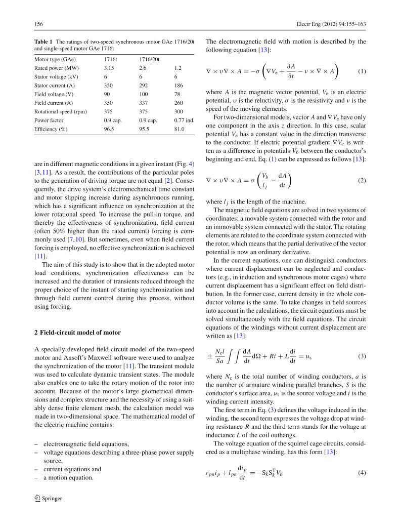
Fig. 1 The circuit part of the model; a diagram of field winding powersupply
An analysis of the experimental calculation results showedthat the optimal number of finite elements in the 2D modelof the investigated synchronous machine was 40,000 knots.
Figure 1 shows the field winding connection diagram ofthe calculation model circuit part. A starting short-circuitingresistor with a resistance ten times higher than that of thefield winding was assumed as R0. Switches for switchingthe windings and changing the number of poles and the rota-tional speed of the motor were incorporated into the circuitmodel. A static exciter with a controlled six-pulse rectifierwas modeled in the field circuit (Fig. 1). Such an exciter isinstalled in the field circuit of the actual motor [5]. Also,gentle synchronization thyristor THGS, enabling switchingon field voltage in a selected instant, was included (Fig. 1).
To verify the calculation model, measurements on theactual motor installed in a mine fan station and the corre-sponding calculations [11] were carried out. A comparisonof the calculation results with the measurements for:
– the amplitudes and the steady-state phase current har-monic spectrum for two different load torques: TL =0.4TN and TL = 0.75TN at the higher rotational speedand TL = 0.45TN and TL = 0.8TN at the lower rotationalspeed,
123
158 Electr Eng (2012) 94:155–163
100
150
200
250
300
350
100 150 200 250 300 350
p=8
p=10
I f [A]
I s [
A]
calculatedmeasured
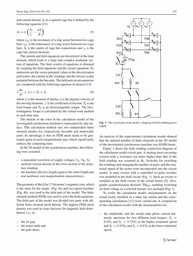
Fig. 2 Calculated and measured curves V for the two rotational speedsof the investigated motor
– the shape of the Mordey curves (Fig. 2),– the active power, the reactive power and the power factor
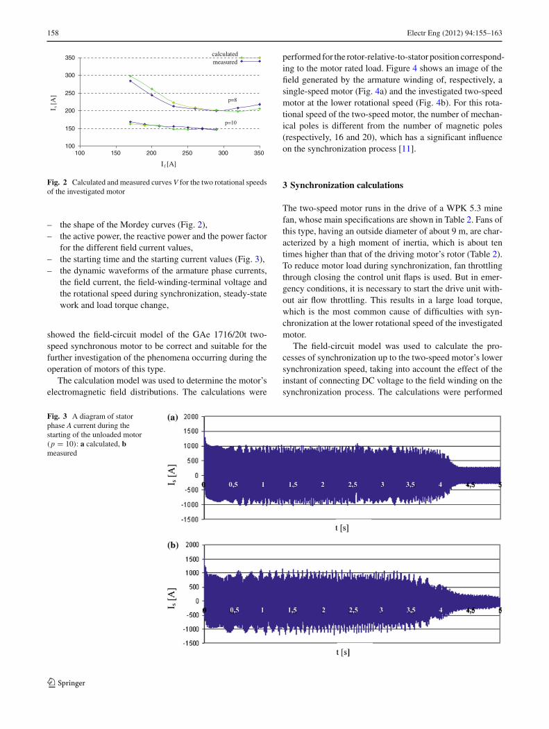
for the different field current values,– the starting time and the starting current values (Fig. 3),– the dynamic waveforms of the armature phase currents,
the field current, the field-winding-terminal voltage andthe rotational speed during synchronization, steady-statework and load torque change,
showed the field-circuit model of the GAe 1716/20t two-speed synchronous motor to be correct and suitable for thefurther investigation of the phenomena occurring during theoperation of motors of this type.
The calculation model was used to determine the motor’selectromagnetic field distributions. The calculations were
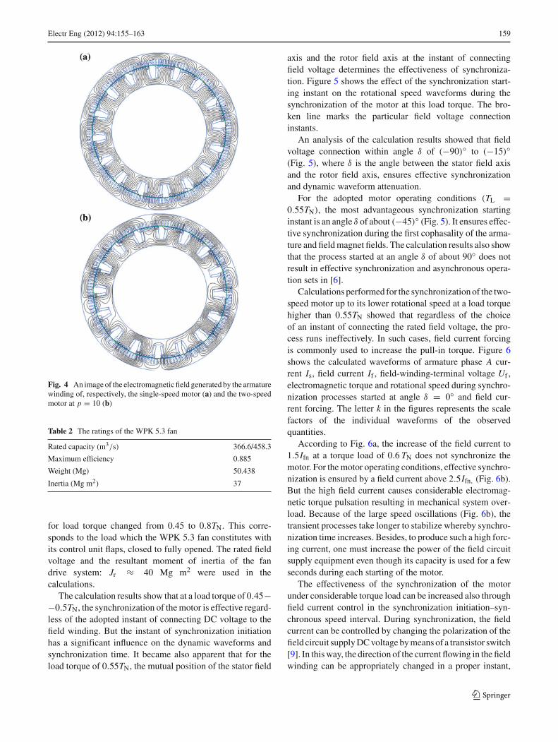
performed for the rotor-relative-to-stator position correspond-ing to the motor rated load. Figure 4 shows an image of thefield generated by the armature winding of, respectively, asingle-speed motor (Fig. 4a) and the investigated two-speedmotor at the lower rotational speed (Fig. 4b). For this rota-tional speed of the two-speed motor, the number of mechan-ical poles is different from the number of magnetic poles(respectively, 16 and 20), which has a significant influenceon the synchronization process [11].
3 Synchronization calculations
The two-speed motor runs in the drive of a WPK 5.3 minefan, whose main specifications are shown in Table 2. Fans ofthis type, having an outside diameter of about 9 m, are char-acterized by a high moment of inertia, which is about tentimes higher than that of the driving motor’s rotor (Table 2).To reduce motor load during synchronization, fan throttlingthrough closing the control unit flaps is used. But in emer-gency conditions, it is necessary to start the drive unit with-out air flow throttling. This results in a large load torque,which is the most common cause of difficulties with syn-chronization at the lower rotational speed of the investigatedmotor.
The field-circuit model was used to calculate the pro-cesses of synchronization up to the two-speed motor’s lowersynchronization speed, taking into account the effect of theinstant of connecting DC voltage to the field winding on thesynchronization process. The calculations were performed
Fig. 3 A diagram of statorphase A current during thestarting of the unloaded motor(p = 10): a calculated, bmeasured
123
Electr Eng (2012) 94:155–163 159
Fig. 4 An image of the electromagnetic field generated by the armaturewinding of, respectively, the single-speed motor (a) and the two-speedmotor at p = 10 (b)
Table 2 The ratings of the WPK 5.3 fan
Rated capacity (m3/s) 366.6/458.3
Maximum efficiency 0.885
Weight (Mg) 50.438
Inertia (Mg m2) 37
for load torque changed from 0.45 to 0.8TN. This corre-sponds to the load which the WPK 5.3 fan constitutes withits control unit flaps, closed to fully opened. The rated fieldvoltage and the resultant moment of inertia of the fandrive system: Jr ≈ 40 Mg m2 were used in thecalculations.
The calculation results show that at a load torque of 0.45−−0.5TN, the synchronization of the motor is effective regard-less of the adopted instant of connecting DC voltage to thefield winding. But the instant of synchronization initiationhas a significant influence on the dynamic waveforms andsynchronization time. It became also apparent that for theload torque of 0.55TN, the mutual position of the stator field
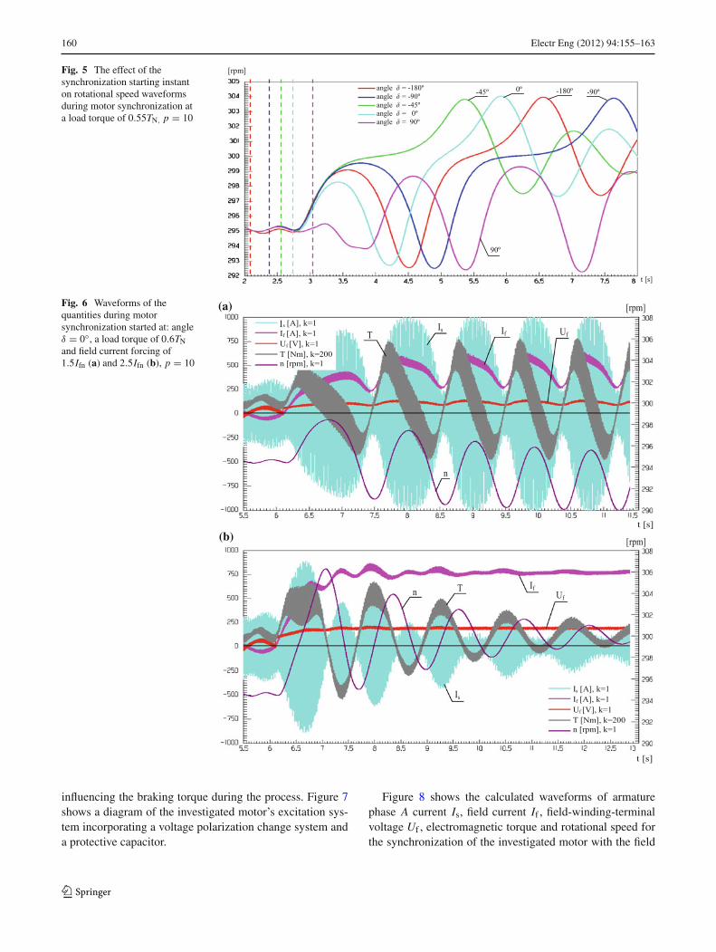
axis and the rotor field axis at the instant of connectingfield voltage determines the effectiveness of synchroniza-tion. Figure 5 shows the effect of the synchronization start-ing instant on the rotational speed waveforms during thesynchronization of the motor at this load torque. The bro-ken line marks the particular field voltage connectioninstants.
An analysis of the calculation results showed that fieldvoltage connection within angle δ of (−90)◦ to (−15)◦(Fig. 5), where δ is the angle between the stator field axisand the rotor field axis, ensures effective synchronizationand dynamic waveform attenuation.
For the adopted motor operating conditions (TL =0.55TN), the most advantageous synchronization startinginstant is an angle δ of about (−45)◦ (Fig. 5). It ensures effec-tive synchronization during the first cophasality of the arma-ture and field magnet fields. The calculation results also showthat the process started at an angle δ of about 90◦ does notresult in effective synchronization and asynchronous opera-tion sets in [6].
Calculations performed for the synchronization of the two-speed motor up to its lower rotational speed at a load torquehigher than 0.55TN showed that regardless of the choiceof an instant of connecting the rated field voltage, the pro-cess runs ineffectively. In such cases, field current forcingis commonly used to increase the pull-in torque. Figure 6shows the calculated waveforms of armature phase A cur-rent Is, field current If , field-winding-terminal voltage Uf ,electromagnetic torque and rotational speed during synchro-nization processes started at angle δ = 0◦ and field cur-rent forcing. The letter k in the figures represents the scalefactors of the individual waveforms of the observedquantities.
According to Fig. 6a, the increase of the field current to1.5Ifn at a torque load of 0.6 TN does not synchronize themotor. For the motor operating conditions, effective synchro-nization is ensured by a field current above 2.5Ifn, (Fig. 6b).But the high field current causes considerable electromag-netic torque pulsation resulting in mechanical system over-load. Because of the large speed oscillations (Fig. 6b), thetransient processes take longer to stabilize whereby synchro-nization time increases. Besides, to produce such a high forc-ing current, one must increase the power of the field circuitsupply equipment even though its capacity is used for a fewseconds during each starting of the motor.
The effectiveness of the synchronization of the motorunder considerable torque load can be increased also throughfield current control in the synchronization initiation–syn-chronous speed interval. During synchronization, the fieldcurrent can be controlled by changing the polarization of thefield circuit supply DC voltage by means of a transistor switch[9]. In this way, the direction of the current flowing in the fieldwinding can be appropriately changed in a proper instant,
123
160 Electr Eng (2012) 94:155–163
Fig. 5 The effect of thesynchronization starting instanton rotational speed waveformsduring motor synchronization ata load torque of 0.55TN, p = 10
t [s]
angle δ = -180ºangle δ = -90º angle δ = -45º angle δ = 0º angle δ = 90º
[rpm]
90º
-45º 0º -180º -90º
Fig. 6 Waveforms of thequantities during motorsynchronization started at: angleδ = 0◦, a load torque of 0.6TNand field current forcing of1.5Ifn (a) and 2.5Ifn (b), p = 10
t [s]
[rpm]s [A], k=1
If [A], k=1 Uf [V], k=1 T [Nm], k=200 n [rpm], k=1
TIs If Uf
n
Is [A], k=1 If [A], k=1 Uf [V], k=1 T [Nm], k=200 n [rpm], k=1
Is
Uf
If Tn
[rpm]
(a)
(b)
t [s]
I
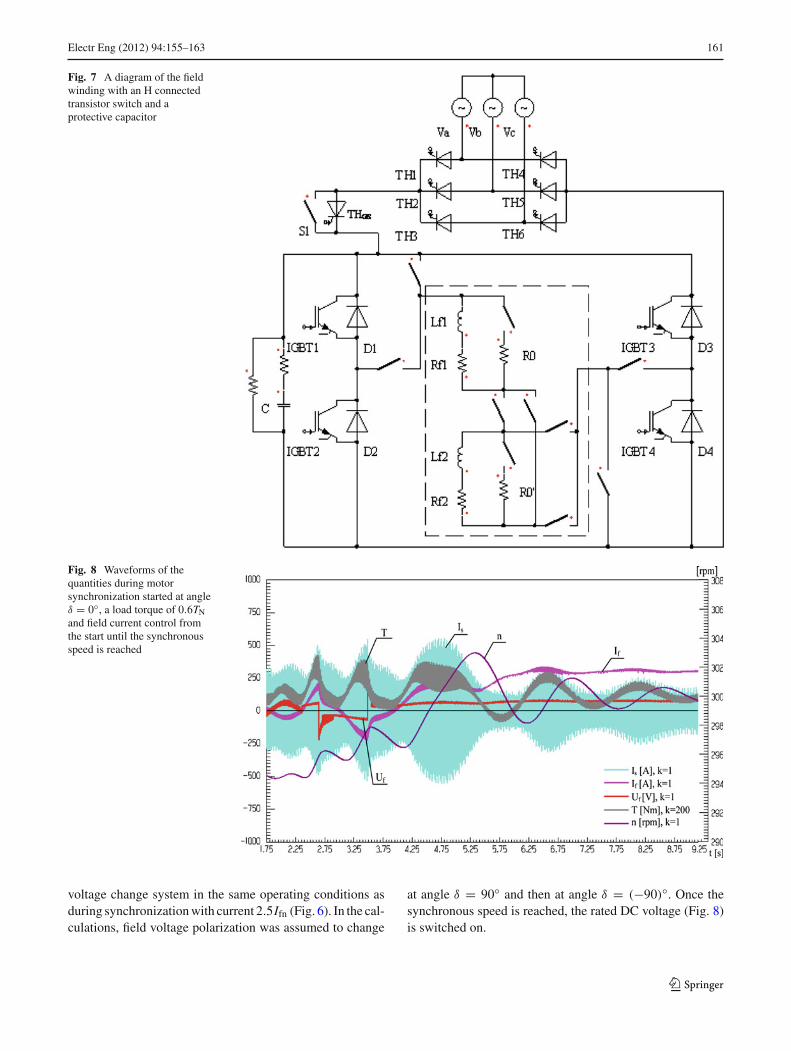
influencing the braking torque during the process. Figure 7shows a diagram of the investigated motor’s excitation sys-tem incorporating a voltage polarization change system anda protective capacitor.
Figure 8 shows the calculated waveforms of armaturephase A current Is, field current If , field-winding-terminalvoltage Uf , electromagnetic torque and rotational speed forthe synchronization of the investigated motor with the field
123
Electr Eng (2012) 94:155–163 161
Fig. 7 A diagram of the fieldwinding with an H connectedtransistor switch and aprotective capacitor
Fig. 8 Waveforms of thequantities during motorsynchronization started at angleδ = 0◦, a load torque of 0.6TNand field current control fromthe start until the synchronousspeed is reached
voltage change system in the same operating conditions asduring synchronization with current 2.5Ifn (Fig. 6). In the cal-culations, field voltage polarization was assumed to change
at angle δ = 90◦ and then at angle δ = (−90)◦. Once thesynchronous speed is reached, the rated DC voltage (Fig. 8)is switched on.
123
162 Electr Eng (2012) 94:155–163
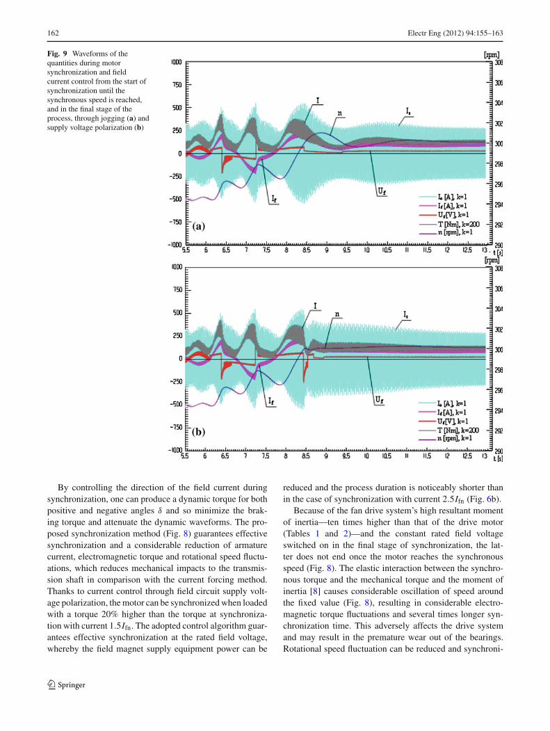
Fig. 9 Waveforms of thequantities during motorsynchronization and fieldcurrent control from the start ofsynchronization until thesynchronous speed is reached,and in the final stage of theprocess, through jogging (a) andsupply voltage polarization (b)
By controlling the direction of the field current duringsynchronization, one can produce a dynamic torque for bothpositive and negative angles δ and so minimize the brak-ing torque and attenuate the dynamic waveforms. The pro-posed synchronization method (Fig. 8) guarantees effectivesynchronization and a considerable reduction of armaturecurrent, electromagnetic torque and rotational speed fluctu-ations, which reduces mechanical impacts to the transmis-sion shaft in comparison with the current forcing method.Thanks to current control through field circuit supply volt-age polarization, the motor can be synchronized when loadedwith a torque 20% higher than the torque at synchroniza-tion with current 1.5Ifn. The adopted control algorithm guar-antees effective synchronization at the rated field voltage,whereby the field magnet supply equipment power can be
reduced and the process duration is noticeably shorter thanin the case of synchronization with current 2.5Ifn (Fig. 6b).
Because of the fan drive system’s high resultant momentof inertia—ten times higher than that of the drive motor(Tables 1 and 2)—and the constant rated field voltageswitched on in the final stage of synchronization, the lat-ter does not end once the motor reaches the synchronousspeed (Fig. 8). The elastic interaction between the synchro-nous torque and the mechanical torque and the moment ofinertia [8] causes considerable oscillation of speed aroundthe fixed value (Fig. 8), resulting in considerable electro-magnetic torque fluctuations and several times longer syn-chronization time. This adversely affects the drive systemand may result in the premature wear out of the bearings.Rotational speed fluctuation can be reduced and synchroni-
123
Electr Eng (2012) 94:155–163 163
zation time much shortened through the proper control of thefield current, also after the motor exceeds the synchronousspeed.
Field current can also be controlled through the periodicjogging (inching) of field circuit supply DC voltage or byappropriately changing the polarization of this voltage. Fig-ure 9 shows the calculated waveforms of armature phase Acurrent Is, field current If , field-winding-terminal voltageUf , electromagnetic torque and rotational speed for the syn-chronization of the investigated motor in the above oper-ating conditions and for field current control also after thesynchronous speed is reached. In the calculations, field cur-rent control was performed as a function of instantaneousmotor rotational speed. Once the motor reached the synchro-nous speed, the exciter thyristor control angle was changedto obtain a minimum rectified voltage (Fig. 9a), or the fieldvoltage polarization was changed (Fig. 9b). The field voltage(Fig. 9a) or its polarization (Fig. 9b) was changed again at theinstant when the motor speed was lower than the synchronousspeed.
Thanks to the methods and algorithm of controlling thefield current in the final stage of synchronization, waveformstabilization time can be significantly reduced. Also, elec-tromagnetic torque and rotational speed fluctuations are sig-nificantly reduced and limited to positive values (Fig. 9a,b) whereby adverse mechanical impacts to the transmissionshaft are minimized.
4 Conclusions
The calculations have shown that through the selection of aproper synchronization initiating instant and through properfield current control, one can increase the effectiveness of thesynchronization process, particularly at a high motor loadtorque. Also electromagnetic torque, armature current androtational speed fluctuations can be considerably reducedin this way (in comparison with the field current forcingmethod), ensuring effective motor synchronization at therated field current. Consequently, the power of the equipmentinstalled in the field magnet supply circuit can be reduced.Field current control in the final stage of synchronizationmakes it possible to minimize rotational speed pulsation andto reduce motor torque variation amplitude and so to atten-uate transients and significantly shorten the synchronizationprocess.
Open Access This article is distributed under the terms of the CreativeCommons Attribution Noncommercial License which permits anynoncommercial use, distribution, and reproduction in any medium,provided the original author(s) and source are credited.
References
1. Antal L, Zawilak J (2001) A two-speed synchronous motor—tech-nical and economical aspects. In: 37th international symposiumon electrical machines SME 2001, Ustron-Zawodzie, 19–22 June,pp 353–360 (in Polish)
2. Antal L, Zawilak J (2003) Torque of two-speed synchronous motorwith switchable armature and field winding. In: 39th internationalsymposium on electrical machines SME 2003. Gdansk-Jurata, 9–11 June, pp 104–112 (in Polish)
3. Antal L, Zawilak J (1996) Magnetic field of the salient–pole2–speed synchronous motor. In: Scientific papers of Instituteof Electric Machines and Drives of Wrocław University ofTechnology, no. 44, Studies and Materials, no. 19, Wrocław,pp 11–20 (in Polish)
4. Antal L, Zawilak J (2004) Two speed synchronous motor test-ing results. In: Exploitation of electrical machines and driver,Ustron, 19–21 May 2004. Research and Development Centreof Electrical Machines “Komel”, no. 68, Katowice, pp 107–112(in Polish)
5. Kaczmarek T, Zawirski K (2000) Drive systems with synchronousmotor, Poznan University of Technology, Poznan (in Polish)
6. Paszek W (1998) Dynamics of electric alternating currentmachines. Gliwice, Helion (in Polish)
7. Sobczyk T (1984) Gentle synchronization of high-power syn-chronous motors out of asynchronous operation. In: 20th interna-tional symposium on electrical machines SME 1984, synchronousmachine, Kazimierz Dolny, pp 28–29 (in Polish)
8. Zalas P, Zawilak J (2006) Soften and reduction duration of syn-chronization process in synchronous motors. 42th internationalsymposium on electrical machines SME 2006, Krakow, 3–6 July,pp 355–358 (in Polish)
9. Zalas P, Zawilak J (2006) Influence of system control of exci-tation current value on synchronization process in synchronousmotors. In: Exploitation of electrical machines and driver, Ustron,17–19 May 2006, Research and Development Centre of ElectricalMachines “Komel”, no. 75, Katowice, pp 83–88, [in Polish]
10. Zalas P, Zawilak J (2005) Selection of excitation start-up momentduring synchronization process in synchronous motors. In: Exploi-tation of electrical machines and driver, Ustron, 18–20 May2005, Research and Development Centre of Electrical Machines“Komel”, no. 71, Katowice, pp 59–64 (in Polish)
11. Zalas P (2007) Analysis of synchronization process of synchronousmotors with asynchronous starting. PhD dissertation, WrocławUniversity of Technology, Wrocław (in Polish)
12. Zawilak J (1986) Pole-changing windings of A.C. machine. In: Sci-entific papers of Institute of Electromachine Systems of WrocławUniversity of Technology, no. 37, series M, no. 7, Wrocław (inPolish)
13. Zhou P, Stanton S, Cendes ZJ (1999) Dynamic modeling of threephase and single phase induction motors. In: Electric machinesand drives, 1999. International Conference IEMD ’99, 9–12 May,pp 556–558
123