TESTING OF A TWO-SPEED SYNCHRONOUS MOTOR · synchronous motors, two-speed, start-up,...
13
synchronous motors, two-speed, start-up, synchronization Ludwik ANTAL*, Jan ZAWILAK* TESTING OF A TWO-SPEED SYNCHRONOUS MOTOR This work shows the results of the tests on a 600/1050kW two-speed synchronous motor with the nominal speeds of 500 and 600 rpm. Motors of this type with powers ranging from 600 to 3150kW are modified single-speed motors. They have been working for several years in coal and copper mines. The use of two-speed drive motors makes it possible to regulate the speed in steps and, thus, regulate the output of the fan and the power drawn by the motor. The possibility of reactive power compensation is intact and mitigation of the motor starting processes is achieved. 1. INTRODUCTION Two-speed synchronous motors were built by replacing the stator winding with a switchable winding and connecting the rotor winding with two pairs of slip-rings located on the opposite sides of the machine. By switching the windings, two different but close in value, numbers of pairs of poles are obtained. Thus, two rotating speeds, differing in values by anywhere from 10 to 20 percent are obtained. Motors of this type, 600 to 3150kW, have been successfully employed for several years in coal and copper mines to drive main fans of the mine exhaust system [1], [2], [3]. The use of two-speed drive mo- tors makes it possible to obtain the required regulation of the speed and, thus, the re- quired change of the output of the fan. The basic advantage of adapting the output of the fan to actual needs is the lowering of the power drawn by it. Speed change from 600 to 500rpm lowers the output of the fan by 17% and the power it draws by 42% [4], [5]. Two-step start of the two-speed motor shows longer starting time but lower maximum starting current than that of a single speed motor and significantly lower reduction of the voltage during startup. A two-speed motor usually works with higher speed. At that speed, the normal ability to compensate reactive power is preserved. Periods of lower demand for air are work free days, equipment repair and maintenance periods, inspection _________ * Politechnika Wrocławska, Instytut Maszyn, Napędów i Pomiarów Elektrycznych, 50-372 Wrocław ul. Smoluchowskiego 19, [email protected], [email protected], [email protected] Prace Naukowe Instytutu Maszyn, Napędów i Pomiarów Elektrycznych Nr 63 Politechniki Wrocławskiej Nr 63 Studia i Materiały Nr 29 2009
Transcript of TESTING OF A TWO-SPEED SYNCHRONOUS MOTOR · synchronous motors, two-speed, start-up,...
synchronous motors, two-speed, start-up, synchronization
Ludwik ANTAL*, Jan ZAWILAK*
TESTING OF A TWO-SPEED SYNCHRONOUS MOTOR
This work shows the results of the tests on a 600/1050kW two-speed synchronous motor with thenominal speeds of 500 and 600 rpm. Motors of this type with powers ranging from 600 to 3150kWare modified single-speed motors. They have been working for several years in coal and coppermines. The use of two-speed drive motors makes it possible to regulate the speed in steps and, thus,regulate the output of the fan and the power drawn by the motor. The possibility of reactive powercompensation is intact and mitigation of the motor starting processes is achieved.
1. INTRODUCTION
Two-speed synchronous motors were built by replacing the stator winding with aswitchable winding and connecting the rotor winding with two pairs of slip-rings locatedon the opposite sides of the machine. By switching the windings, two different but closein value, numbers of pairs of poles are obtained. Thus, two rotating speeds, differing invalues by anywhere from 10 to 20 percent are obtained. Motors of this type, 600 to3150kW, have been successfully employed for several years in coal and copper mines todrive main fans of the mine exhaust system [1], [2], [3]. The use of two-speed drive mo-tors makes it possible to obtain the required regulation of the speed and, thus, the re-quired change of the output of the fan. The basic advantage of adapting the output of thefan to actual needs is the lowering of the power drawn by it. Speed change from 600 to500rpm lowers the output of the fan by 17% and the power it draws by 42% [4], [5].Two-step start of the two-speed motor shows longer starting time but lower maximumstarting current than that of a single speed motor and significantly lower reduction of thevoltage during startup. A two-speed motor usually works with higher speed. At thatspeed, the normal ability to compensate reactive power is preserved. Periods of lowerdemand for air are work free days, equipment repair and maintenance periods, inspection_________
* Politechnika Wrocławska, Instytut Maszyn, Napędów i Pomiarów Elektrycznych, 50-372 Wrocławul. Smoluchowskiego 19, [email protected], [email protected],[email protected]
Prace Naukowe Instytutu Maszyn, Napędów i Pomiarów ElektrycznychNr 63 Politechniki Wrocławskiej Nr 63Studia i Materiały Nr 29 2009
18
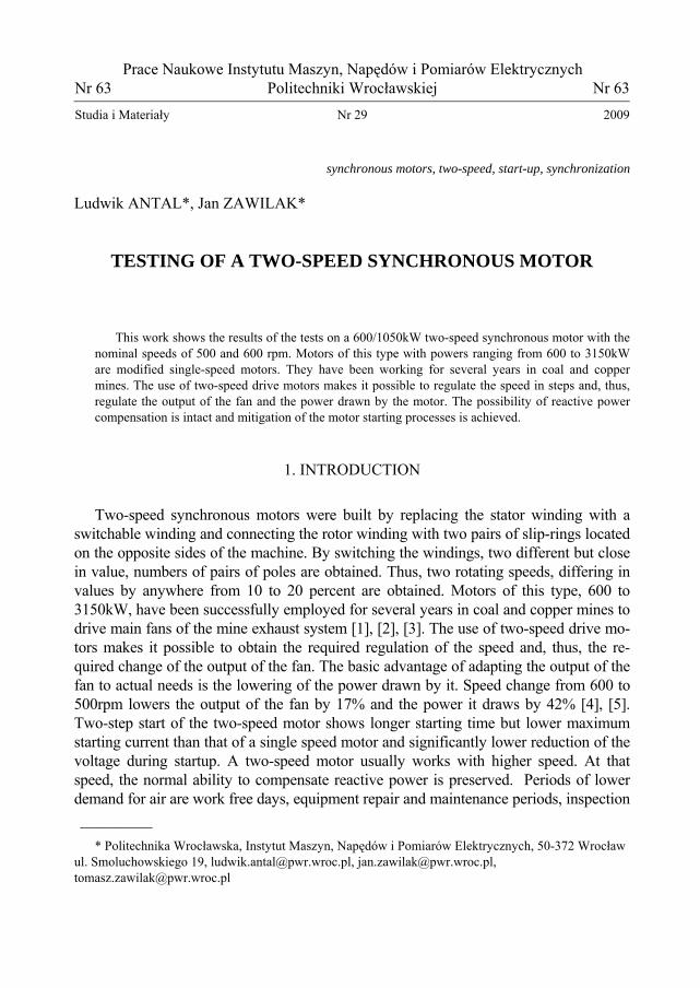
times etc. In those periods, the demand for capacitive reactive power is very low there-fore, with the lower speed working conditions, the need for reactive power compensationis not anticipated. Asymmetric winding of the stator and asymmetric connection of thefield winding while working at the lower speed, result in deformation of the stator cur-rents, non-uniform warming of the machine elements and increased level of motor framevibration. Establishing the permissible level of these negative occurrences is the scopeof the tests described in this work. The tests on the motor were conducted during themanufacturing phase and also after the motor was installed in work position in the mine.
Fig. 1. Tested synchronous motor coupled with fan
During the tests the following values were monitored: voltage, armature and fieldcurrents as well as the rotating speed during direct starting, asynchronous running at theset value, synchronization and loading of the motor on both rotating speeds. Vibration ofthe bearings and motor frame as well as the temperature distribution were also moni-tored. Recording of the armature currents of the loaded motor and analysis of its har-monics made it possible to assess the degree of the current distortion caused by theasymmetry of the magnetic circuit. That asymmetry was the condition for obtaining thesecond, lower rotating speed. Asynchronous running allowed determination of the syn-chronous reactance of the machine in both of its axes. This work shows the results of thetests on a 600/1050kW motor (fig. 1 and 2).
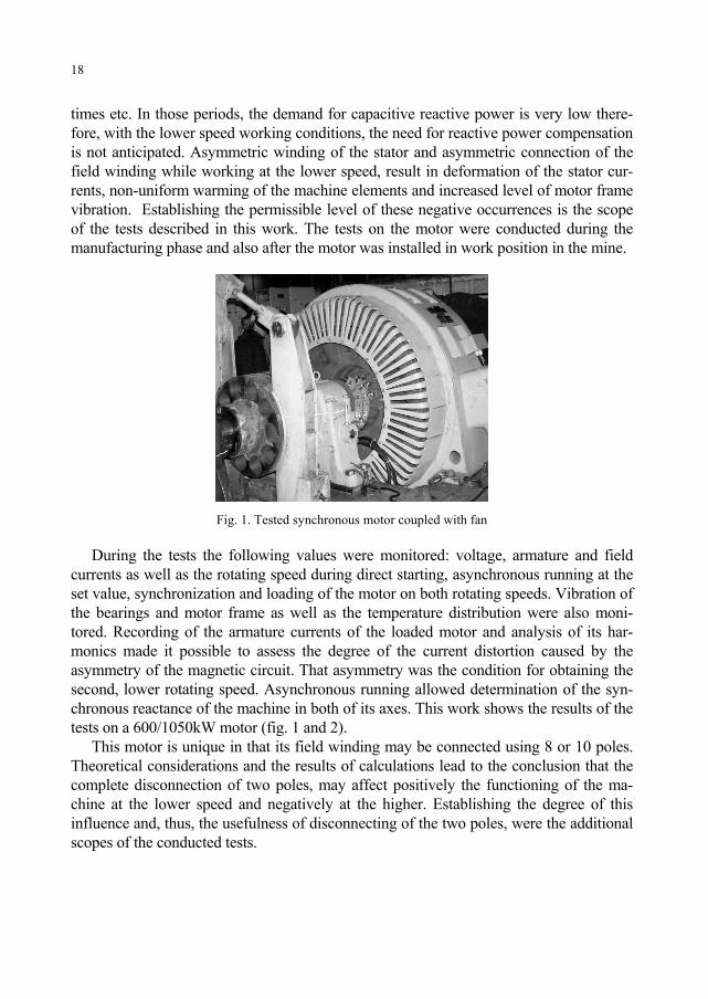
This motor is unique in that its field winding may be connected using 8 or 10 poles.Theoretical considerations and the results of calculations lead to the conclusion that thecomplete disconnection of two poles, may affect positively the functioning of the ma-chine at the lower speed and negatively at the higher. Establishing the degree of thisinfluence and, thus, the usefulness of disconnecting of the two poles, were the additionalscopes of the conducted tests.
19
Fig. 2. Disconnectable pole of the field winding
2. TWO-STEP STARTUP
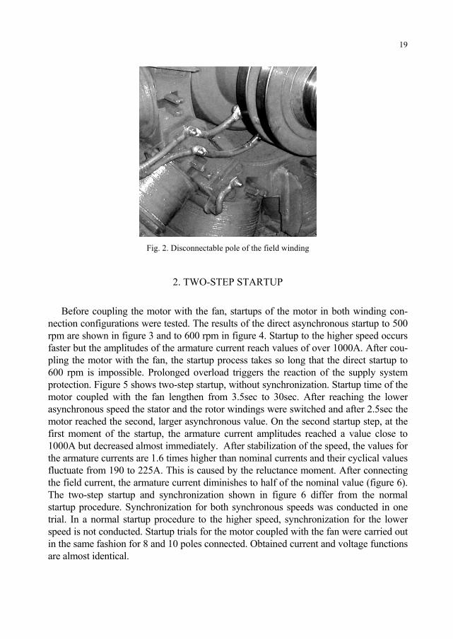
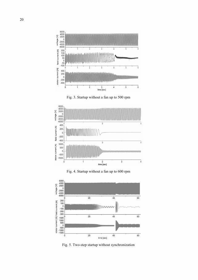
Before coupling the motor with the fan, startups of the motor in both winding con-nection configurations were tested. The results of the direct asynchronous startup to 500rpm are shown in figure 3 and to 600 rpm in figure 4. Startup to the higher speed occursfaster but the amplitudes of the armature current reach values of over 1000A. After cou-pling the motor with the fan, the startup process takes so long that the direct startup to600 rpm is impossible. Prolonged overload triggers the reaction of the supply systemprotection. Figure 5 shows two-step startup, without synchronization. Startup time of themotor coupled with the fan lengthen from 3.5sec to 30sec. After reaching the lowerasynchronous speed the stator and the rotor windings were switched and after 2.5sec themotor reached the second, larger asynchronous value. On the second startup step, at thefirst moment of the startup, the armature current amplitudes reached a value close to1000A but decreased almost immediately. After stabilization of the speed, the values forthe armature currents are 1.6 times higher than nominal currents and their cyclical valuesfluctuate from 190 to 225A. This is caused by the reluctance moment. After connectingthe field current, the armature current diminishes to half of the nominal value (figure 6).The two-step startup and synchronization shown in figure 6 differ from the normalstartup procedure. Synchronization for both synchronous speeds was conducted in onetrial. In a normal startup procedure to the higher speed, synchronization for the lowerspeed is not conducted. Startup trials for the motor coupled with the fan were carried outin the same fashion for 8 and 10 poles connected. Obtained current and voltage functionsare almost identical.
20
Fig. 3. Startup without a fan up to 500 rpm
Fig. 4. Startup without a fan up to 600 rpm
Fig. 5. Two-step startup without synchronization
21
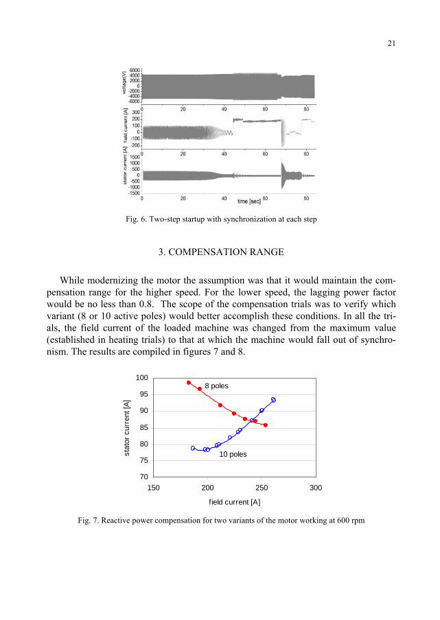
Fig. 6. Two-step startup with synchronization at each step
3. COMPENSATION RANGE
While modernizing the motor the assumption was that it would maintain the com-pensation range for the higher speed. For the lower speed, the lagging power factorwould be no less than 0.8. The scope of the compensation trials was to verify whichvariant (8 or 10 active poles) would better accomplish these conditions. In all the tri-als, the field current of the loaded machine was changed from the maximum value(established in heating trials) to that at which the machine would fall out of synchro-nism. The results are compiled in figures 7 and 8.
70
75
80
85
90
95
100
150 200 250 300
field current [A]
stat
or c
urre
nt [A
]
10 poles
8 poles
Fig. 7. Reactive power compensation for two variants of the motor working at 600 rpm
22
50
60
70
80
90
100
110
50 100 150 200 250
field current [A]
stat
or c
urre
nt [A
]
10 poles
8 poles
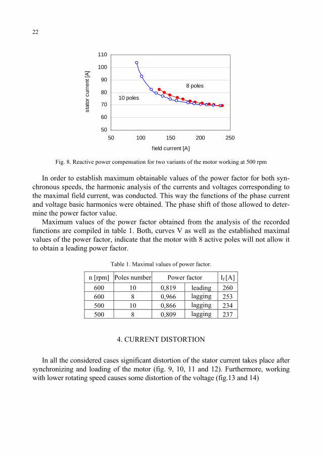
Fig. 8. Reactive power compensation for two variants of the motor working at 500 rpm
In order to establish maximum obtainable values of the power factor for both syn-chronous speeds, the harmonic analysis of the currents and voltages corresponding tothe maximal field current, was conducted. This way the functions of the phase currentand voltage basic harmonics were obtained. The phase shift of those allowed to deter-mine the power factor value.
Maximum values of the power factor obtained from the analysis of the recordedfunctions are compiled in table 1. Both, curves V as well as the established maximalvalues of the power factor, indicate that the motor with 8 active poles will not allow itto obtain a leading power factor.
Table 1. Maximal values of power factor.
n [rpm] Poles number Power factor If [A]600 10 0,819 leading 260600 8 0,966 lagging 253500 10 0,866 lagging 234500 8 0,809 lagging 237
4. CURRENT DISTORTION
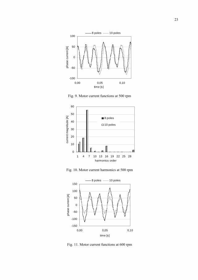
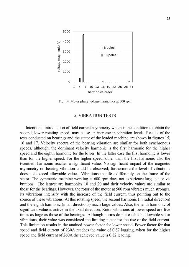
In all the considered cases significant distortion of the stator current takes place aftersynchronizing and loading of the motor (fig. 9, 10, 11 and 12). Furthermore, workingwith lower rotating speed causes some distortion of the voltage (fig.13 and 14)
23
-100
-50
0
50
100
0,00 0,05 0,10time [s]
phas
e cu
rren
t [A
]
8 poles 10 poles
Fig. 9. Motor current functions at 500 rpm
0
10
20
30
40
50
60
1 4 7 10 13 16 19 22 25 28harmonics order
curr
ent m
agni
tude
[A]
8 poles
10 poles
Fig. 10. Motor current harmonics at 500 rpm
-150
-100
-50
0
50
100
150
0,00 0,05 0,10
time [s]
phas
e cu
rrent
[A]
8 poles 10 poles
Fig. 11. Motor current functions at 600 rpm
24
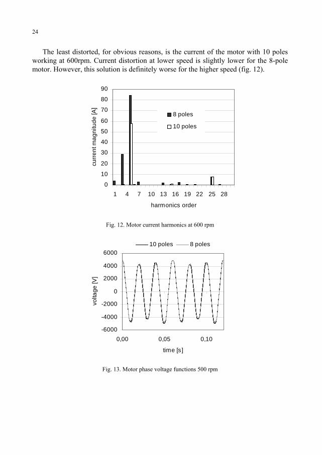
The least distorted, for obvious reasons, is the current of the motor with 10 polesworking at 600rpm. Current distortion at lower speed is slightly lower for the 8-polemotor. However, this solution is definitely worse for the higher speed (fig. 12).
0
10
20
30
40
50
60
70
80
90
1 4 7 10 13 16 19 22 25 28
harmonics order
curr
ent m
agni
tude
[A]
8 poles
10 poles
Fig. 12. Motor current harmonics at 600 rpm
-6000
-4000
-2000
0
2000
4000
6000
0,00 0,05 0,10
time [s]
volta
ge [V
]
10 poles 8 poles
Fig. 13. Motor phase voltage functions 500 rpm
25
0
1000
2000
3000
4000
5000
1 4 7 10 13 16 19 22 25 28 31
harmonics order
volta
ge m
agni
tude
[V]
8 poles
10 poles
Fig. 14. Motor phase voltage harmonics at 500 rpm
5. VIBRATION TESTS
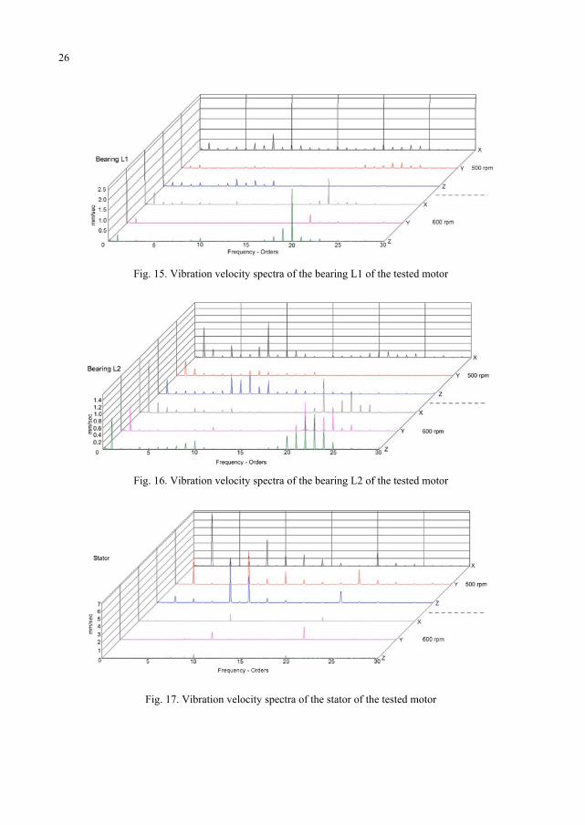
Intentional introduction of field current asymmetry which is the condition to obtain thesecond, lower rotating speed, may cause an increase in vibration levels. Results of thetests conducted on bearings and the stator of the loaded machine are shown in figures 15,16 and 17. Velocity spectra of the bearing vibration are similar for both synchronousspeeds, although, the dominant velocity harmonic is the first harmonic for the higherspeed and the eighth harmonic for the lower. In the latter case the first harmonic is lowerthan for the higher speed. For the higher speed, other than the first harmonic also thetwentieth harmonic reaches a significant value. No significant impact of the magneticasymmetry on bearing vibration could be observed; furthermore the level of vibrationsdoes not exceed allowable values. Vibrations manifest differently on the frame of thestator. The symmetric machine working at 600 rpm does not experience large stator vi-brations. The largest are harmonics 10 and 20 and their velocity values are similar tothose for the bearings. However, the rotor of the motor at 500 rpm vibrates much stronger.Its vibrations intensify with the increase of the field current, thus pointing out to thesource of these vibrations. At this rotating speed, the second harmonic (in radial direction)and the eighth harmonic (in all directions) reach large values. Also, the tenth harmonic ofsignificant value is active in the axial direction. Rotor vibrations at lower speed are fivetimes as large as those of the bearings. Although norms do not establish allowable statorvibrations, their value was considered the limiting factor for the rise of the field current.This limitation results in the attained power factor for lower speed. Power factor for thatspeed and field current of 230A reaches the value of 0.87 lagging, when for the higherspeed and field current of 260A the achieved value is 0.82 leading.
26
Fig. 15. Vibration velocity spectra of the bearing L1 of the tested motor
Fig. 16. Vibration velocity spectra of the bearing L2 of the tested motor
Fig. 17. Vibration velocity spectra of the stator of the tested motor
27
6. HEATING
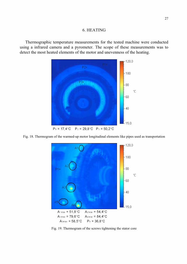
Thermographic temperature measurements for the tested machine were conductedusing a infrared camera and a pyrometer. The scope of these measurements was todetect the most heated elements of the motor and unevenness of the heating.
Fig. 18. Thermogram of the warmed-up motor longitudinal elements like pipes used as transportation
Fig. 19. Thermogram of the screws tightening the stator core
28
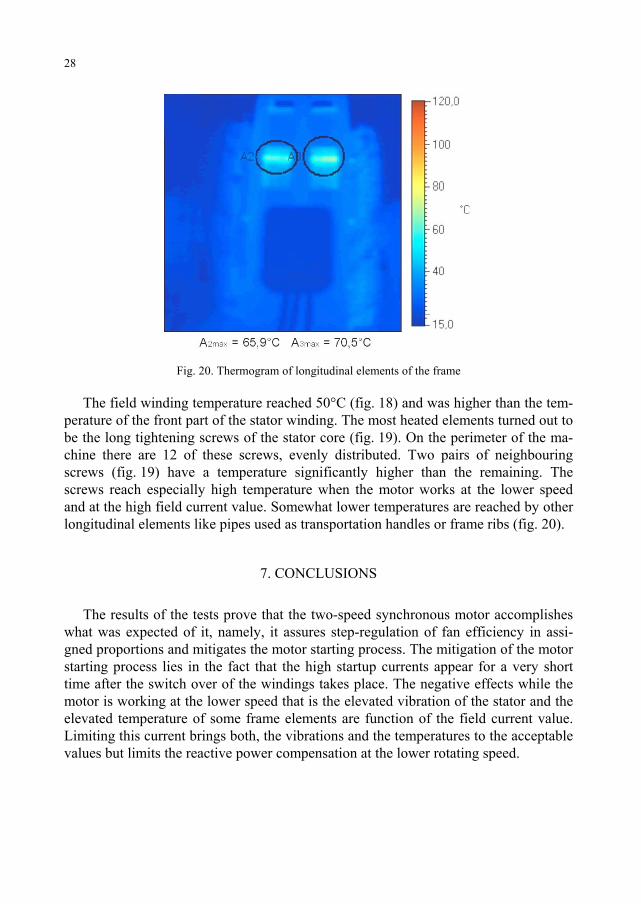
Fig. 20. Thermogram of longitudinal elements of the frame
The field winding temperature reached 50°C (fig. 18) and was higher than the tem-perature of the front part of the stator winding. The most heated elements turned out tobe the long tightening screws of the stator core (fig. 19). On the perimeter of the ma-chine there are 12 of these screws, evenly distributed. Two pairs of neighbouringscrews (fig. 19) have a temperature significantly higher than the remaining. Thescrews reach especially high temperature when the motor works at the lower speedand at the high field current value. Somewhat lower temperatures are reached by otherlongitudinal elements like pipes used as transportation handles or frame ribs (fig. 20).
7. CONCLUSIONS
The results of the tests prove that the two-speed synchronous motor accomplisheswhat was expected of it, namely, it assures step-regulation of fan efficiency in assi-gned proportions and mitigates the motor starting process. The mitigation of the motorstarting process lies in the fact that the high startup currents appear for a very shorttime after the switch over of the windings takes place. The negative effects while themotor is working at the lower speed that is the elevated vibration of the stator and theelevated temperature of some frame elements are function of the field current value.Limiting this current brings both, the vibrations and the temperatures to the acceptablevalues but limits the reactive power compensation at the lower rotating speed.
29
Presented research was done within Project No. 3 T10A 005 26 financed by State Committee for Sci-entific Research – Poland.
REFERENCES
[1] Antal L., Zawilak J., Magnetic field of the salient-pole 2-speed synchronous motor, Scientific Papersof the Institute of Electrical Machines, Drives and Metrology of the Wroclaw University of Technol-ogy, No. 45, pp. 11-21, Wroclaw, 1996 (in Polish)
[2] Antal L. Zawilak J., Torque of two-speed synchronous motor, 34th International Symposium onElectrical Machines (SME’98), pp. 89-95, 15- 18 June 1998, Lodz
[3] Antal L. Zawilak J., Reactive power compensation by the two-speed synchronous motor of fractionalspeed ratio, – 36th International Symposium on Electrical Machines (SME’2000), pp. 122-130, 2000,Szklarska Poręba, (in Polish)
[4] Antal L., Zawilak J., A two-speed synchronous motor – technical and economical aspects, 37th Inter-national Symposium on Electrical Machines. (SME'2001), pp. 353-360, 19-22 June 2001, Ustron-Zawodzie, (In Polish)
[5] Antal L., Zawilak J., Vibrations of two-speed synchronous motor, 38th International Symposium onElectrical Machines. (SME'2002), pp. 109-118, June 18-21, 2002, Cedzyna-Kielce, (In Polish)