GENERIC INSTALLATION GUIDE (WALLS) - TECHO …€¦ · GENERIC INSTALLATION GUIDE ... FOR...
21
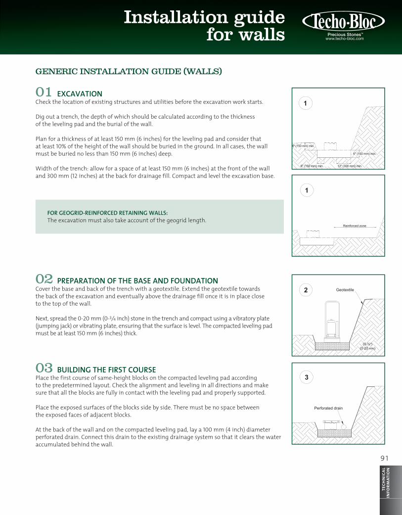
91 Installation guide for walls technical information GENERIC INSTALLATION GUIDE (WALLS) 01 EXCAVATION Check the location of existing structures and utilities before the excavation work starts. Dig out a trench, the depth of which should be calculated according to the thickness of the leveling pad and the burial of the wall. Plan for a thickness of at least 150 mm (6 inches) for the leveling pad and consider that at least 10% of the height of the wall should be buried in the ground. In all cases, the wall must be buried no less than 150 mm (6 inches) deep. Width of the trench: allow for a space of at least 150 mm (6 inches) at the front of the wall and 300 mm (12 inches) at the back for drainage fill. Compact and level the excavation base. FOR GEOGRID-REINFORCED RETAINING WALLS: The excavation must also take account of the geogrid length. 02 PREPARATION OF THE BASE AND FOUNDATION Cover the base and back of the trench with a geotextile. Extend the geotextile towards the back of the excavation and eventually above the drainage fill once it is in place close to the top of the wall. Next, spread the 0-20 mm (0- 3 / 4 inch) stone in the trench and compact using a vibratory plate (jumping jack) or vibrating plate, ensuring that the surface is level. The compacted leveling pad must be at least 150 mm (6 inches) thick. 03 BUILDING THE FIRST COURSE Place the first course of same-height blocks on the compacted leveling pad according to the predetermined layout. Check the alignment and leveling in all directions and make sure that all the blocks are fully in contact with the leveling pad and properly supported. Place the exposed surfaces of the blocks side by side. There must be no space between the exposed faces of adjacent blocks. At the back of the wall and on the compacted leveling pad, lay a 100 mm (4 inch) diameter perforated drain. Connect this drain to the existing drainage system so that it clears the water accumulated behind the wall. 6" (150 mm) min. 6" (150 mm) min. 6" (150 mm) min. 12" (300 mm) min. Perforated drain Reinforced zone (0-¾") (0-20 mm) Geotextile
Transcript of GENERIC INSTALLATION GUIDE (WALLS) - TECHO …€¦ · GENERIC INSTALLATION GUIDE ... FOR...
9 1
Installation guide for walls
tech
nica
lin
form
atio
n
GENERIC INSTALLATION GUIDE (WALLS)
01 EXCAVATIONCheck the location of existing structures and utilities before the excavation work starts.
Dig out a trench, the depth of which should be calculated according to the thickness of the leveling pad and the burial of the wall.
Plan for a thickness of at least 150 mm (6 inches) for the leveling pad and consider that at least 10% of the height of the wall should be buried in the ground. In all cases, the wall must be buried no less than 150 mm (6 inches) deep.
Width of the trench: allow for a space of at least 150 mm (6 inches) at the front of the wall and 300 mm (12 inches) at the back for drainage fill. Compact and level the excavation base.
FOR GEOGRID-REINFORCED RETAINING WALLS:The excavation must also take account of the geogrid length.
02 PREPARATION OF THE BASE AND FOUNDATIONCover the base and back of the trench with a geotextile. Extend the geotextile towards the back of the excavation and eventually above the drainage fill once it is in place close to the top of the wall.
Next, spread the 0-20 mm (0-3⁄4 inch) stone in the trench and compact using a vibratory plate (jumping jack) or vibrating plate, ensuring that the surface is level. The compacted leveling pad must be at least 150 mm (6 inches) thick.
03 BUILDING THE FIRST COURSEPlace the first course of same-height blocks on the compacted leveling pad according to the predetermined layout. Check the alignment and leveling in all directions and make sure that all the blocks are fully in contact with the leveling pad and properly supported.
Place the exposed surfaces of the blocks side by side. There must be no space between the exposed faces of adjacent blocks.
At the back of the wall and on the compacted leveling pad, lay a 100 mm (4 inch) diameter perforated drain. Connect this drain to the existing drainage system so that it clears the water accumulated behind the wall.
6" (150 mm) min.
6" (150 mm) min.
6" (150 mm) min.
Reinforced zone
3 ft (0.9 m)
12" (300 mm) min.
(0-¾")(0-20 mm)
Geotextile
Perforated drain
6" (150 mm) min.
6" (150 mm) min.
6" (150 mm) min.
Reinforced zone
3 ft (0.9 m)
12" (300 mm) min.
(0-¾")(0-20 mm)
Geotextile
Perforated drain
6" (150 mm) min.
6" (150 mm) min.
6" (150 mm) min.
Reinforced zone
3 ft (0.9 m)
12" (300 mm) min.
(0-¾")(0-20 mm)
Geotextile
Perforated drain
6" (150 mm) min.
6" (150 mm) min.
6" (150 mm) min.
Reinforced zone
3 ft (0.9 m)
12" (300 mm) min.
(0-¾")(0-20 mm)
Geotextile
Perforated drain
92
tech
nica
lin
form
atio
nInstallation guide for walls
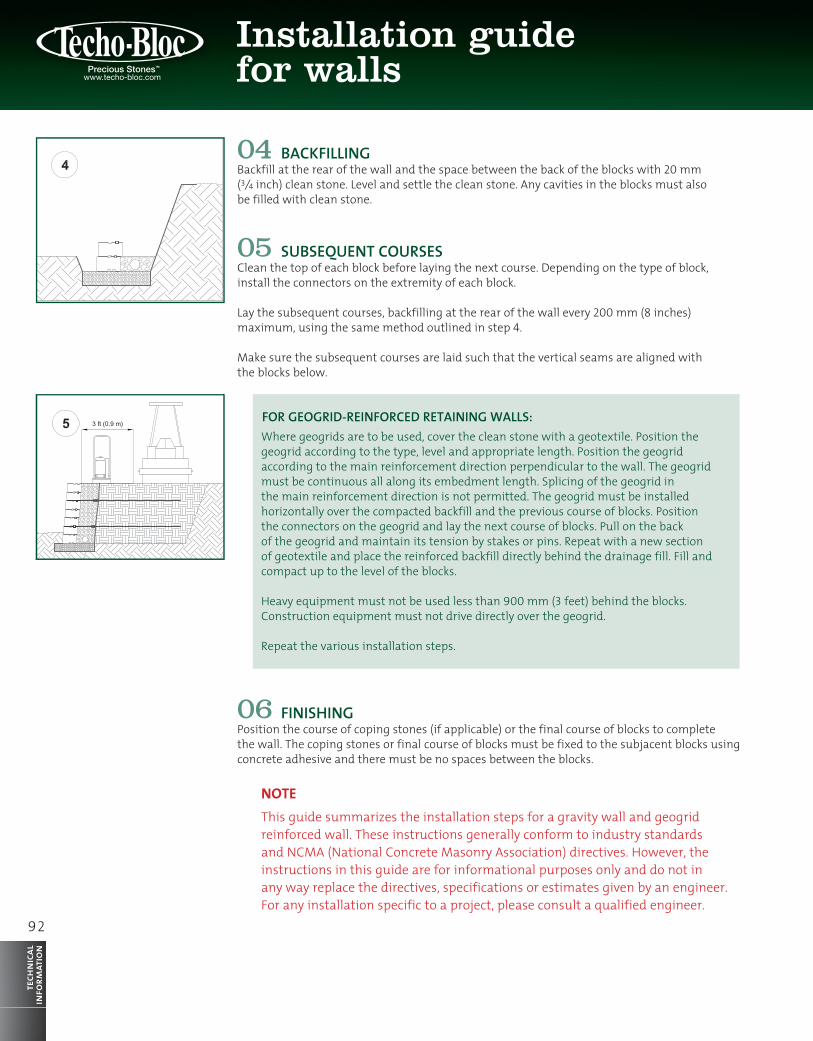
04 BACKFILLINGBackfill at the rear of the wall and the space between the back of the blocks with 20 mm (3⁄4 inch) clean stone. Level and settle the clean stone. Any cavities in the blocks must also be filled with clean stone.
05 SUBSEQUENT COURSESClean the top of each block before laying the next course. Depending on the type of block, install the connectors on the extremity of each block.
Lay the subsequent courses, backfilling at the rear of the wall every 200 mm (8 inches) maximum, using the same method outlined in step 4.
Make sure the subsequent courses are laid such that the vertical seams are aligned with the blocks below.
FOR GEOGRID-REINFORCED RETAINING WALLS:Where geogrids are to be used, cover the clean stone with a geotextile. Position the geogrid according to the type, level and appropriate length. Position the geogrid according to the main reinforcement direction perpendicular to the wall. The geogrid must be continuous all along its embedment length. Splicing of the geogrid in the main reinforcement direction is not permitted. The geogrid must be installed horizontally over the compacted backfill and the previous course of blocks. Position the connectors on the geogrid and lay the next course of blocks. Pull on the back of the geogrid and maintain its tension by stakes or pins. Repeat with a new section of geotextile and place the reinforced backfill directly behind the drainage fill. Fill and compact up to the level of the blocks.
Heavy equipment must not be used less than 900 mm (3 feet) behind the blocks.Construction equipment must not drive directly over the geogrid.
Repeat the various installation steps.
06 FINISHINGPosition the course of coping stones (if applicable) or the final course of blocks to complete the wall. The coping stones or final course of blocks must be fixed to the subjacent blocks using concrete adhesive and there must be no spaces between the blocks.
NOTEThis guide summarizes the installation steps for a gravity wall and geogrid reinforced wall. These instructions generally conform to industry standards and NCMA (National Concrete Masonry Association) directives. However, the instructions in this guide are for informational purposes only and do not in any way replace the directives, specifications or estimates given by an engineer. For any installation specific to a project, please consult a qualified engineer.
6" (150 mm) min.
6" (150 mm) min.
6" (150 mm) min.
Reinforced zone
3 ft (0.9 m)
12" (300 mm) min.
(0-¾")(0-20 mm)
Geotextile
Perforated drain
6" (150 mm) min.
6" (150 mm) min.
6" (150 mm) min.
Reinforced zone
3 ft (0.9 m)
12" (300 mm) min.
(0-¾")(0-20 mm)
Geotextile
Perforated drain
9 3
tech
nica
lin
form
atio
n
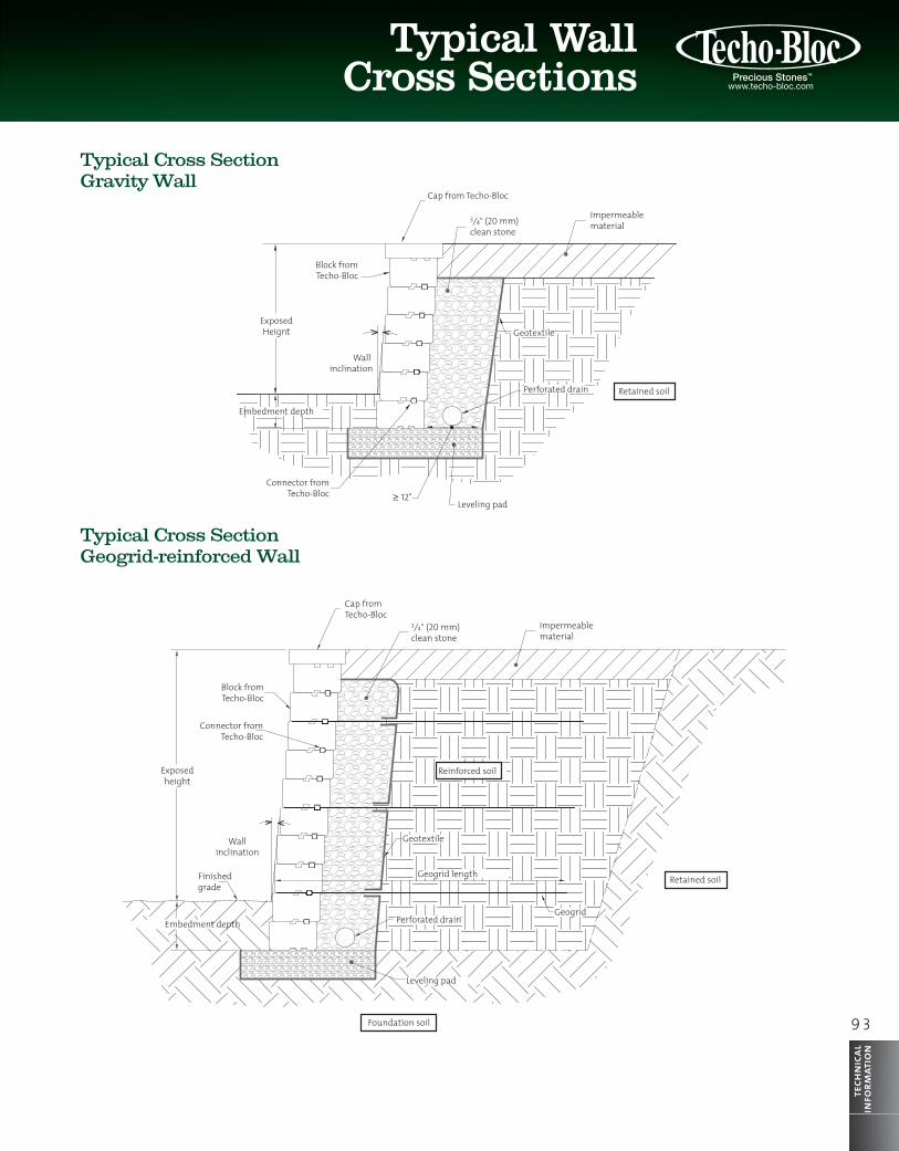
Cap from Techo-Bloc
3⁄4" (20 mm) clean stone
Impermeable material
Geotextile
Perforated drain
Leveling pad≥ 12"
Connector fromTecho-Bloc
Block fromTecho-Bloc
ExposedHeignt
Embedment depth
Wall inclination
Cap fromTecho-Bloc
3⁄4" (20 mm) clean stone
Impermeable material
Retained soil
Retained soil
Foundation soil
Leveling pad
GeogridPerforated drain
Geogrid length
GeotextileWallinclination
Connector from Techo-Bloc
Exposedheight
Embedment depth
Finishedgrade
Reinforced soil
Block fromTecho-Bloc
Typical Cross SectionGravity Wall
Typical Cross SectionGeogrid-reinforced Wall
Typical WallCross Sections
94
tech
nica
lin
form
atio
n
Insert connectorin groove
Setback / wall inclination
Setback / wall inclinaison
Connector is insertedin the front groove
Connector is insertedint he front groove
Connector is insertedint he back groove
Connector is insertedin the back groove
Front of unit
Front of unit The setback is determinedby the placement of the connector
Front of unit
Frontof unit
Notch
Back groove
Front groove
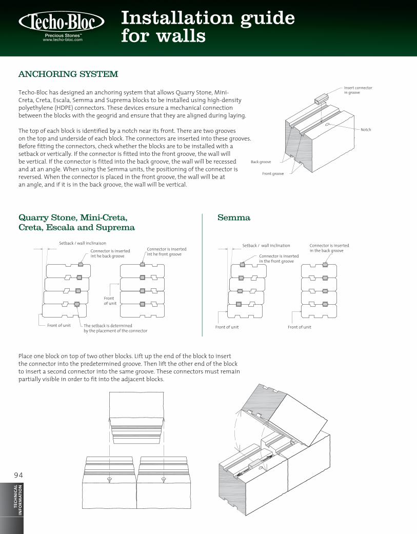
ANCHORING SYSTEM
Techo-Bloc has designed an anchoring system that allows Quarry Stone, Mini-Creta, Creta, Escala, Semma and Suprema blocks to be installed using high-density polyethylene (HDPE) connectors. These devices ensure a mechanical connection between the blocks with the geogrid and ensure that they are aligned during laying.
The top of each block is identified by a notch near its front. There are two grooves on the top and underside of each block. The connectors are inserted into these grooves. Before fitting the connectors, check whether the blocks are to be installed with a setback or vertically. If the connector is fitted into the front groove, the wall will be vertical. If the connector is fitted into the back groove, the wall will be recessed and at an angle. When using the Semma units, the positioning of the connector is reversed. When the connector is placed in the front groove, the wall will be at an angle, and if it is in the back groove, the wall will be vertical.
Place one block on top of two other blocks. Lift up the end of the block to insert the connector into the predetermined groove. Then lift the other end of the block to insert a second connector into the same groove. These connectors must remain partially visible in order to fit into the adjacent blocks.
Quarry Stone, Mini-Creta, Creta, Escala and Suprema
Semma
Installation guide for walls

9 5
Typical WallCross Sections
tech
nica
lin
form
atio
n
Geogrid
However, when creating internal curves and the connectors are in the back groove, you must fit two connectors on each block as illustrated.
When using a geogrid, it must be laid before the connectors are fitted. The connectors will therefore be placed above the geogrid. After positioning it, move the block forward until it touches the connectors and locks the system.
Repeat the installation steps for the adjacent blocks.
INSTALLATION PATTERNS: QUARRY STONE
Techo-Bloc has developed installation patterns that can be used as part of your projects when building Quarry Stone walls. These patterns will help give your walls a more natural finish and are also a useful tool in helping to estimate the quantity of blocks needed for each project.
MODULES
The Quarry Stone system is comprised of blocks known as modules. These modules come in two heights: 100 mm (315⁄16 inches) and 200 mm (7 7⁄8 inches). The 100 mm high modules are called Quarry Stone 100 and the 200 mm modules are called Quarry Stone 200.
QUARRY STONE 100
Quarry Stone 100 modules are divided into three lengths. Modules “A” are 200 mm (7 7⁄8 inches) long, modules B are 300 mm (1113⁄16 inches) long, and modules C and D are 400 mm (153⁄4 inches) long.
Geogrid
Geogrid

96
tech
nica
lin
form
atio
nInstallation guide for walls
Number of blocks required
66.7%
33.3%
QUARRY STONE 200
Quarry Stone 200 modules are divided into three lengths. Modules “A” are 200 mm (77⁄8 inches) long, modules B are 300 mm (1113⁄16 inches) long, and modules C and D are 400 mm (153⁄4 inches) long.
Note: Imperial dimensions are approximate.
COMBINATIONS
The designs of these patterns are largely based on three models: the 1-row model, 2-row model and 3-row model. Each model contains different examples of module combinations. The same combination example can be used several times or combined with other combination examples. Depending on the height of the wall or whether a geogrid is used, combination examples with different models can be used for the same wall. (Note: only modules A, B and C have been used to illustrate the different length modules).
8.9 ft (2.7 m)
7 7⁄8 in (200 mm)
15 3⁄4 in (400 mm)
23 5⁄8 in (600 mm)
5.9 ft (1.8 m)
9.8 ft (3 m)
7 7 /8 in(200 mm)
11 13 /16 in(300 mm)
11 13 /16 in(300 mm)
15 3 /4 in(400 mm)
15 3 /4 in(400 mm)
15 3 /4 in(400 mm)
15 3 /4 in(400 mm)
15 3 /4 in(400 mm)
13 3 /4 in(350 mm)
15 3 /4 in(400 mm)
11 13 /16 in(300 mm)
11 13 /16 in(300 mm)
7 7 /8 in(200 mm)
14 3 /4 in(200 mm)
5 7 /8 in(150 mm)
9 13 /16 in(250 mm)
11 13 /16 in(300 mm)
13 3 /4 in(350 mm)
15 3 /4 in(400 mm)
14 3 /4 in(375 mm)
7 7/8 in
(200 mm)
3 15/16 in
(100 mm)
9 13 /16 in(250 mm)
11 13 /16 in(300 mm)
5 7 /8 in(150 mm)
9 1 /16 in(230 mm)
Quarry Stone 200 (A) 300 (B) 400 (C)
Quarry Stone 100 4 4 4
Quarry Stone 200 1 1 1
M O D U L E L E N G T H (mm)
Pattern – 1-row model 66.7% Quarry Stone 100 mm – 33.3% Quarry Stone 200 mm

9 7
Quarry Stone
tech
nica
lin
form
atio
n
Pattern – 2-row model 75% Quarry Stone 100 mm – 25% Quarry Stone 200 mm
Number of blocks required
75%
25%
8.9 ft (2.7 m)
7 7⁄8 in (200 mm)
15 3⁄4 in (400 mm)
23 5⁄8 in (600 mm)
5.9 ft (1.8 m)
9.8 ft (3 m)
7 7 /8 in(200 mm)
11 13 /16 in(300 mm)
11 13 /16 in(300 mm)
15 3 /4 in(400 mm)
15 3 /4 in(400 mm)
15 3 /4 in(400 mm)
15 3 /4 in(400 mm)
15 3 /4 in(400 mm)
13 3 /4 in(350 mm)
15 3 /4 in(400 mm)
11 13 /16 in(300 mm)
11 13 /16 in(300 mm)
7 7 /8 in(200 mm)
14 3 /4 in(200 mm)
5 7 /8 in(150 mm)
9 13 /16 in(250 mm)
11 13 /16 in(300 mm)
13 3 /4 in(350 mm)
15 3 /4 in(400 mm)
14 3 /4 in(375 mm)
7 7/8 in
(200 mm)
3 15/16 in
(100 mm)
9 13 /16 in(250 mm)
11 13 /16 in(300 mm)
5 7 /8 in(150 mm)
9 1 /16 in(230 mm)
Quarry Stone 200 (A) 300 (B) 400 (C)
Quarry Stone 100 6 6 6
Quarry Stone 200 1 1 1
M O D U L E L E N G T H ( M M )
8.9 ft (2.7 m)
7 7⁄8 in (200 mm)
15 3⁄4 in (400 mm)
23 5⁄8 in (600 mm)
5.9 ft (1.8 m)
9.8 ft (3 m)
7 7 /8 in(200 mm)
11 13 /16 in(300 mm)
11 13 /16 in(300 mm)
15 3 /4 in(400 mm)
15 3 /4 in(400 mm)
15 3 /4 in(400 mm)
15 3 /4 in(400 mm)
15 3 /4 in(400 mm)
13 3 /4 in(350 mm)
15 3 /4 in(400 mm)
11 13 /16 in(300 mm)
11 13 /16 in(300 mm)
7 7 /8 in(200 mm)
14 3 /4 in(200 mm)
5 7 /8 in(150 mm)
9 13 /16 in(250 mm)
11 13 /16 in(300 mm)
13 3 /4 in(350 mm)
15 3 /4 in(400 mm)
14 3 /4 in(375 mm)
7 7/8 in
(200 mm)
3 15/16 in
(100 mm)
9 13 /16 in(250 mm)
11 13 /16 in(300 mm)
5 7 /8 in(150 mm)
9 1 /16 in(230 mm)
Pattern – 3-row model 60% Quarry Stone 100 mm – 40% Quarry Stone 200 mm
Number of blocks required
60%
40%
Quarry Stone 200 (A) 300 (B) 400 (C)
Quarry Stone 100 12 12 12
Quarry Stone 200 4 4 4
M O D U L E L E N G T H ( M M )
8.9 ft (2.7 m)
7 7⁄8 in (200 mm)
One-Row model – Combination examples 33.3% Quarry Stone 100 mm – 66.7% Quarry Stone 200 mm

98
tech
nica
lin
form
atio
nInstallation guide for walls
Two-Row model – Combination examples 75% Quarry Stone 100 mm – 25% Quarry Stone 200 mm
Quarry Stone 100 = 75% of surface Quarry Stone 200 = 25% of surface
5.9 ft (1.8 m)
15 3⁄4 in (400 mm)
GEOGRIDS(when applicable)
7⁄8"
, ,
The 1-row model includes six combination examples. Each combination is 8.9 ft. (2.7 m) long and 7 7⁄8" (200 mm) high. This model can be used to lay the last course of modules or when the other models cannot be used.
Quarry Stone 100 = 67% of surface Quarry Stone 200 = 33% of surface
The 2-row model includes four combination examples. Each combination is 1.8 m long and 153⁄4" (400 mm) high. This model gives a leveled surface every 153⁄4" (400 mm), which is the usual spacing between geogrid levels in a Quarry Stone wall. Consultation of this model is recommended when using a geogrid.
9 9
Quarry Stone
tech
nica
lin
form
atio
n
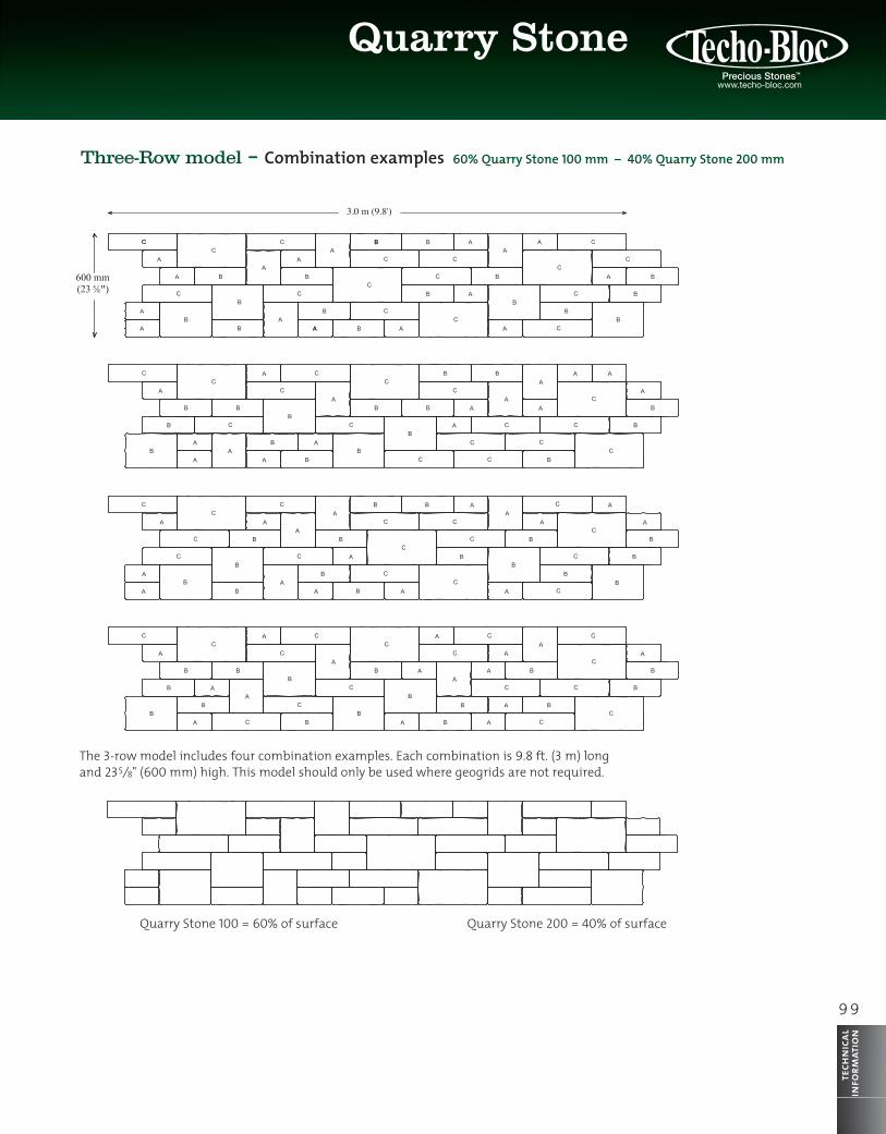
Three-Row model – Combination examples 60% Quarry Stone 100 mm – 40% Quarry Stone 200 mm
3.0 m (9.8')
5⁄8"
3,0 m (9,8')
5⁄8"
The 3-row model includes four combination examples. Each combination is 9.8 ft. (3 m) long and 235⁄8" (600 mm) high. This model should only be used where geogrids are not required.
Quarry Stone 100 = 60% of surface Quarry Stone 200 = 40% of surface

100
tech
nica
lin
form
atio
nInstallation guide for walls
PatternsDifferent patterns for Quarry Stone
&
&
INSTALLATION PATTERNS: MINI-CRETA
Techo-Bloc has devised installation patterns that can be used as part of your projects when building Mini-Creta walls. These patterns will help give your walls a more naturalfinish and are also a useful tool in helping estimatethe quantity of blocks needed for each project.
Note: Imperial dimensions are approximate.

1 0 1
Mini-Creta
tech
nica
lin
form
atio
n
Pattern – 3-row model 77.8% Mini-Creta 3" – 22.2% Mini-Creta 6"
Number of blocks required
77.8%
22.2%
MODULES
The Mini-Creta system is comprised of blocks known as modules. These modules come in two heights: 75 mm (215⁄16 inches) and 150 mm (57⁄8 inches). The 75 mm high modules are called Mini-Creta 3" and the 150 mm modules are called Mini-Creta 6".
MINI-CRETA 3" AND MINI-CRETA 6"
The Mini-Creta 3" and Mini-Creta 6" modules are divided into three lengths. Modules “A” are 230 mm (91⁄16 inches) long, modules B are 300 mm (1113⁄16 inches) long and modules C and D are 375 mm (143⁄4 inches) long.
COMBINATIONS
The design of these patterns is largely based on three models: the 1-row model, 3-row model and 5-row model. Each model contains different examples of module combinations. The same combination example can be used several times or combined with other combination examples. Depending on the height of the wall or whether a geogrid is used, combination examples from different models can be used for the same wall. (Note: only modules A, B and C have been used to illustrate the different length modules).
8.9 ft (2.7 m)
8.9 ft (2.7 m)
5 7/8 in (150 mm)
17 11/16 in (450 mm)
29 1/2 in (750 mm)
8.9 ft (2.7 m)
9 1 /16 in
(230 mm)9 13/16 in
(250 mm)
9 13/16 in(250 mm)
11 13 /16 in
(300 mm)
11 13 /16 in
(300 mm)
14 3 /4 in
(375 mm)
14 3 /4 in
(375 mm)
5 7/8 in
(150 mm)
2 15/16 in
(75 mm)
7 1 /16 in
(180 mm)
9 13 /16 in
(250 mm)
11 13 /16 in
(300 mm)
12 13 /16 in
(325 mm)
13 3 /4 in
(350 mm)
9 1 /16 in
(230 mm)
11 13 /16 in
(300 mm)
11 13 /16 in
(300 mm)
14 3 /4 in
(375 mm)
14 3 /4 in
(375 mm)
7 1 /16 in
(180 mm)
9 13 /16 in
(250 mm)
11 13 /16 in
(300 mm)
12 13 /16 in
(325 mm)
13 3 /4 in
(350 mm)
Mini-Creta 230 (A) 300 (B) 375 (C)
Mini-Creta 3" 14 14 14
Mini-Creta 6" 2 2 2
M O D U L E L E N G T H ( M M )
Pattern – 1-row model 66.7% Mini-Creta 3" – 33.3% Mini-Creta 6"
Number of blocks required
66.7%
33.3%
Mini-Creta 230 (A) 300 (B) 375 (C)
Mini-Creta 3" 4 4 4
Mini-Creta 6" 1 1 1
M O D U L E L E N G T H ( M M )8.9 ft (2.7 m)
8.9 ft (2.7 m)
5 7/8 in (150 mm)
17 11/16 in (450 mm)
29 1/2 in (750 mm)
8.9 ft (2.7 m)
9 1 /16 in
(230 mm)9 13/16 in
(250 mm)
9 13/16 in(250 mm)
11 13 /16 in
(300 mm)
11 13 /16 in
(300 mm)
14 3 /4 in
(375 mm)
14 3 /4 in
(375 mm)
5 7/8 in
(150 mm)
2 15/16 in
(75 mm)
7 1 /16 in
(180 mm)
9 13 /16 in
(250 mm)
11 13 /16 in
(300 mm)
12 13 /16 in
(325 mm)
13 3 /4 in
(350 mm)
9 1 /16 in
(230 mm)
11 13 /16 in
(300 mm)
11 13 /16 in
(300 mm)
14 3 /4 in
(375 mm)
14 3 /4 in
(375 mm)
7 1 /16 in
(180 mm)
9 13 /16 in
(250 mm)
11 13 /16 in
(300 mm)
12 13 /16 in
(325 mm)
13 3 /4 in
(350 mm)
102
tech
nica
lin
form
atio
nInstallation guide for walls
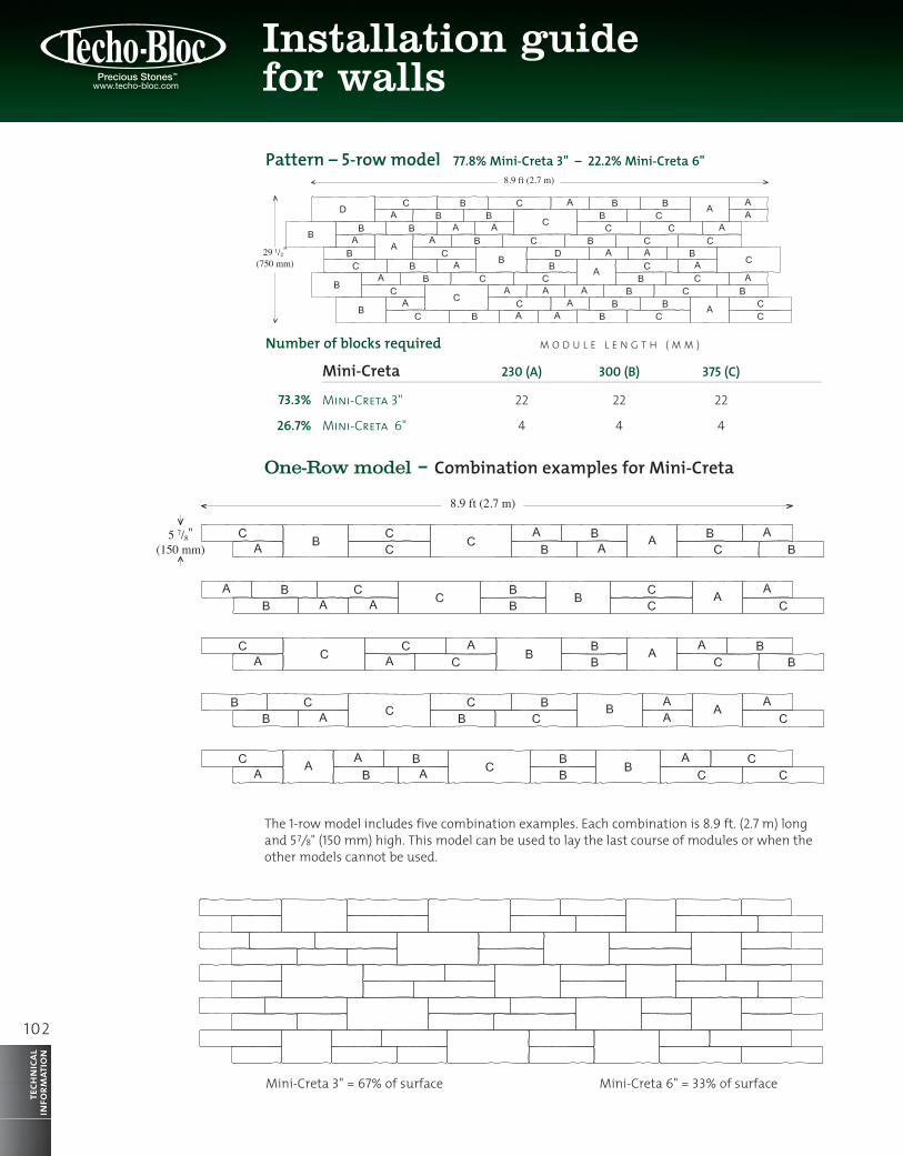
Pattern – 5-row model 77.8% Mini-Creta 3" – 22.2% Mini-Creta 6"
Number of blocks required
73.3%
26.7%
Mini-Creta 230 (A) 300 (B) 375 (C)
Mini-Creta 3" 22 22 22
Mini-Creta 6" 4 4 4
M O D U L E L E N G T H ( M M )
One-Row model – Combination examples for Mini-Creta
8.9 ft (2.7 m)
6" = 33%3" = 67%
5 7/8" (150 mm)
2,7 m (8,9’)
7⁄8"
The 1-row model includes five combination examples. Each combination is 8.9 ft. (2.7 m) long and 57⁄8" (150 mm) high. This model can be used to lay the last course of modules or when the other models cannot be used.
Mini-Creta 3" = 67% of surface Mini-Creta 6" = 33% of surface
8.9 ft (2.7 m)
8.9 ft (2.7 m)
5 7/8" (150 mm)
17 11/16" (450 mm)
29 1/2" (750 mm)
8.9 ft (2.7 m)

1 0 3
Mini-Creta
tech
nica
lin
form
atio
n
Pattern – 5-row model 77.8% Mini-Creta 3" – 22.2% Mini-Creta 6"
Number of blocks required
73.3%
26.7%
One-Row model – Combination examples for Mini-Creta
8.9 ft (2.7 m)
6" = 22%3" = 78%
17 11⁄16" (450 mm)
GEOGRIDS(When applicable)
2,7 m (8.9')
Three-Row modelCombination examples for Mini-Creta
The 3-row model includes four combination examples. Each combination is 8.9 ft. (2.7 m) long and 17 11⁄16" (450 mm) high. This model gives a leveled surface every 17 11⁄16" (450 mm), which is the usual spacing between geogrid levels in a Mini-Creta wall. Consultation of this model is recommended when using a geogrid.
Mini-Creta 3" = 78% of surface Mini-Creta 6" = 22% of surface
104
tech
nica
lin
form
atio
n
8.9 ft (2.7 m)
6" = 27%3" = 73%
29 1⁄2" (750 mm)
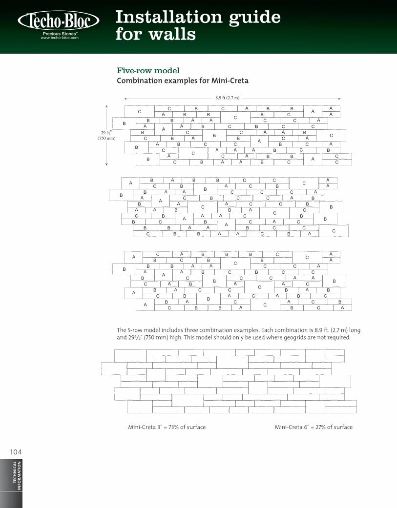
Five-row modelCombination examples for Mini-Creta
The 5-row model includes three combination examples. Each combination is 8.9 ft. (2.7 m) long and 291⁄2" (750 mm) high. This model should only be used where geogrids are not required.
Mini-Creta 3" = 73% of surface Mini-Creta 6" = 27% of surface
Installation guide for walls
1 0 5
tech
nica
lin
form
atio
n
Five-row modelCombination examples for Mini-Creta
Corners
WALL A
WALL B WALL B WALL B
LONGESTMODULES
The construction of an interior corner is achieved by alternating the Extension of walls A and B.
GEOGRID EXTENSION AT LEAST 25% OF TOTALHEIGHT OF THE WALL
THE END OF WALL B IS ALIGNED WITH BACK OF WALL A
THE END OF WALL A IS ALIGNED WITH BACK OF WALL B
LONGESTMODULES
LONGESTMODULES
THE END OF WALL B IS ALIGNED WITH BACK OF WALL A
WALL A WALL A
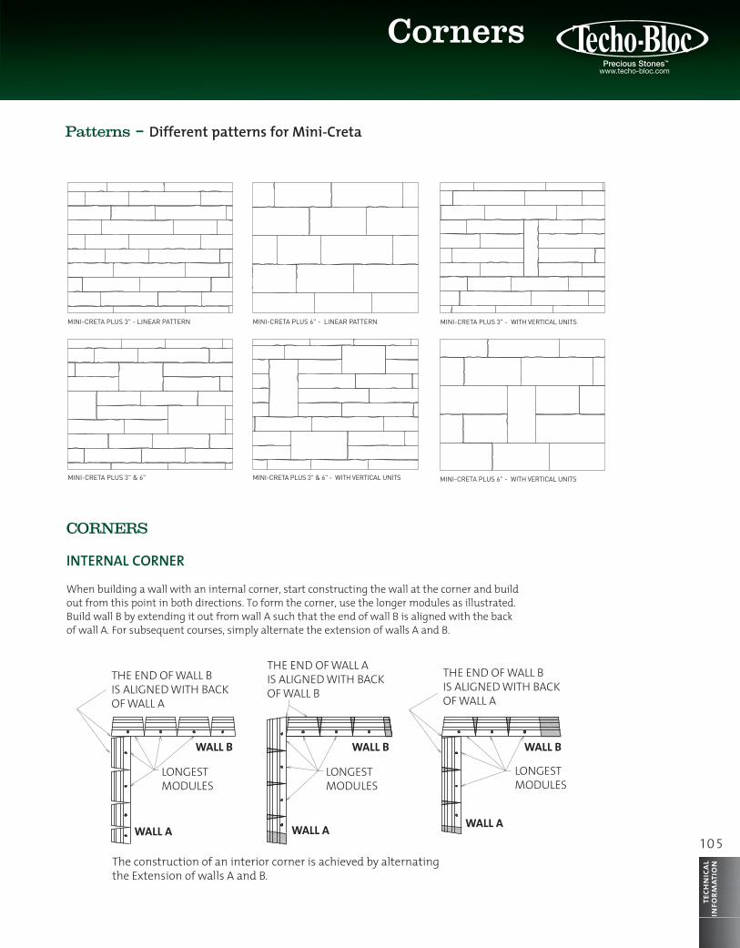
Patterns – Different patterns for Mini-Creta
MINI-CRETA PLUS 6" - LINEAR PATTERN
MINI-CRETA PLUS 3" & 6" - WITH VERTICAL UNITSMINI-CRETA PLUS 3" & 6"
MINI-CRETA PLUS 6" - WITH VERTICAL UNITSMINI-CRETA PLUS 3" - WITH VERTICAL UNITS
MINI-CRETA PLUS 3" - LINEAR PATTERN
MINI-CRETA PLUS 6" - LINEAR PATTERN
MINI-CRETA PLUS 3" & 6" - WITH VERTICAL UNITSMINI-CRETA PLUS 3" & 6"
MINI-CRETA PLUS 6" - WITH VERTICAL UNITSMINI-CRETA PLUS 3" - WITH VERTICAL UNITS
MINI-CRETA PLUS 3" - LINEAR PATTERN
MINI-CRETA PLUS 6" - LINEAR PATTERN
MINI-CRETA PLUS 3" & 6" - WITH VERTICAL UNITSMINI-CRETA PLUS 3" & 6"
MINI-CRETA PLUS 6" - WITH VERTICAL UNITSMINI-CRETA PLUS 3" - WITH VERTICAL UNITS
MINI-CRETA PLUS 3" - LINEAR PATTERN
CORNERS
INTERNAL CORNER
When building a wall with an internal corner, start constructing the wall at the corner and build out from this point in both directions. To form the corner, use the longer modules as illustrated. Build wall B by extending it out from wall A such that the end of wall B is aligned with the back of wall A. For subsequent courses, simply alternate the extension of walls A and B.

WALL A
WALL B WALL B WALL B
LONGESTMODULES
The construction of an interior corner is achieved by alternating the Extension of walls A and B.
GEOGRID EXTENSION AT LEAST 25% OF TOTALHEIGHT OF THE WALL
THE END OF WALL B IS ALIGNED WITH BACK OF WALL A
THE END OF WALL A IS ALIGNED WITH BACK OF WALL B
LONGESTMODULES
LONGESTMODULES
THE END OF WALL B IS ALIGNED WITH BACK OF WALL A
WALL A WALL A
106
tech
nica
lin
form
atio
nInstallation guide for walls
RAINURES LA RÉALISATION D’UN COIN EST FAITE, SOIT EN GUILLOTINANT OU EN CISELANT LE COIN TEL QUE DÉMONTRÉ CI-DESSOUS.
ALTERNER LADIRECTION DUBLOC DE COIN
GROOVES SPLIT DOWN THE UNITS AT THE LOCATION WITH NO GROOVES
ALTERNATE THEDIRECTION OF
THE CORNER UNIT
EXTERNAL CORNER
For walls with an internal corner, start building the wall from the corner and continue from this point in both directions. Each pallet contains units that can be used to make a corner. On-site, these units (except the Suprema blocks) must be split down the side using a hammer and chisel in order to obtain a corner unit. For each subsequent course, alternate the direction of the corner unit and secure the corner unit to the block below using concrete adhesive.
If you are using a geogrid, allow at least 75 mm (3 inches) of backfill between the overlapping layers of geogrids.
If you are using a geogrid, this must be extended beyond the internal corner by at least 25% of the total height of the wall. Alternate the extension of the geogrid for subsequent layers.
1 0 7
Curves
tech
nica
lin
form
atio
n
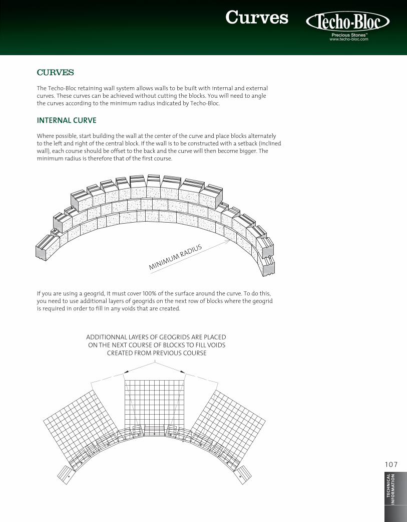
CURVES
The Techo-Bloc retaining wall system allows walls to be built with internal and external curves. These curves can be achieved without cutting the blocks. You will need to angle the curves according to the minimum radius indicated by Techo-Bloc.
INTERNAL CURVE
Where possible, start building the wall at the center of the curve and place blocks alternately to the left and right of the central block. If the wall is to be constructed with a setback (inclined wall), each course should be offset to the back and the curve will then become bigger. The minimum radius is therefore that of the first course.
If you are using a geogrid, it must cover 100% of the surface around the curve. To do this, you need to use additional layers of geogrids on the next row of blocks where the geogrid is required in order to fill in any voids that are created.
MINIMUM RADIUS
ADDITIONNAL LAYERS OF GEOGRIDS ARE PLACED ON THE NEXT COURSE OF BLOCKS TO FILL VOIDS
CREATED FROM PREVIOUS COURSE
MINIMUM RADIUS
ADDITIONNAL LAYERS OF GEOGRIDS ARE PLACED ON THE NEXT COURSE OF BLOCKS TO FILL VOIDS
CREATED FROM PREVIOUS COURSE
MINIMUM RADIUS
GEOGRID LAYERS MUST HAVE ATLEAST 75 MM (3") OF BACKFILLBETWEEN OVERLAPPING GEOGRID
MINIMUM RADIUS
GEOGRID LAYERS MUST HAVE ATLEAST 75 MM (3") OF BACKFILLBETWEEN OVERLAPPING GEOGRID
108
tech
nica
lin
form
atio
nInstallation guide for walls
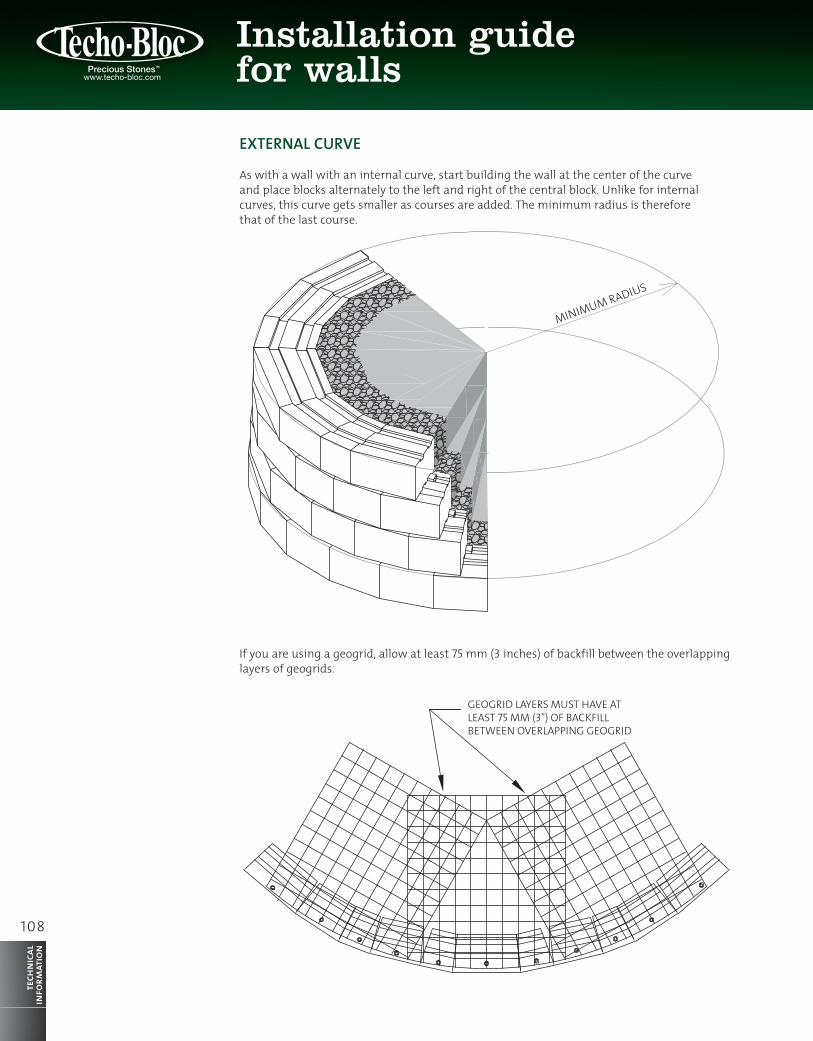
EXTERNAL CURVE
As with a wall with an internal curve, start building the wall at the center of the curve and place blocks alternately to the left and right of the central block. Unlike for internal curves, this curve gets smaller as courses are added. The minimum radius is therefore that of the last course.
If you are using a geogrid, allow at least 75 mm (3 inches) of backfill between the overlapping layers of geogrids.

1 0 9
tech
nica
lin
form
atio
n
CUT MARKS
CUT WITH A CHISELOR SPLITTER
ALTERNATE THE POSITION OF THE CUT CORNERAS SHOWN BELOW
ALTERNATE THE CORNER UNIT FOR EACHSUBSEQUENT COURSE AS SHOWN ABOVE
CUT WITHA SAW
STEPPED FOUNDATION
A wall built on an incline requires stepped foundations, and for steep inclines, several steps may be required. Construction should start at the lowest level. Each of the steps must follow a level horizontal path and the vertical distance separating the successive steps must equal the height of a block.
BLOCKS
STEPPED FOUNDATION
CUT MARKS
CUT WITH A CHISELOR SPLITTER
CUT WITHA SAW
ALTEALTEAL RNATE THE POSITION OF THE CUT CORNERAS SHOWN BELOW
OBLIQUE CORNER
The longer modules should be used to build an oblique external corner. Cut the non-exposed part of the block using a saw. Use a chisel or splitter to give the exposed face of the block a textured look. Alternate the cutting of the blocks for each subsequent course.

110
tech
nica
lin
form
atio
nInstallation guide for walls
GEOGRID CUT PERPENDICULAR TO WALL (CREATING TWO GEOGRID PANELS)
GEOGRID FOLDED AROUND FORMWORK TUBE
FORMWORK TUBE INSTALLED DURING WALL CONSTRUCTION
GEOGRID CUT PERPENDICULARTO WALL (CREATING TWO GEOGRID PANELS)
GEOGRID FOLDEDAROUND POST
POST INSTALLED DUSTALLED DUST RINGWALL CONTRUCTION
FENCING
Fencing can be erected behind the blocks. The fence posts must be placed in formwork tubes positioned during construction of the wall, and then filled with concrete. The geogrids may be cut to accommodate installation of the tubes. Cut the geogrid in alignment with the center of the formwork tube and perpendicular to the wall, thus creating two geogrid panels. Connect the two geogrid panels at the front and back of the formwork tube and bend the geogrid to fit around the formwork.
GUARD RAIL
As with fencing, a guard rail can be incorporated behind the blocks. The guard rail posts must be installed during construction of the wall. The geogrid is cut perpendicular to the wall and in alignment with the center of the post, thus creating two geogrid panels. These two panels are connected at the front and back of the post. The geogrid can be bent to fit around the post.
1 1 1
tech
nica
lin
form
atio
n
UPPER WALL
D
H1
LOWER WALL
UPPER WALL
GEOGRID
H2
LOWER WALL
H2
H1
THEN THE WALLS ARE GENERALLYINDEPENDENT OF EACH OTHER, OTHERWISE THE CONSTRUCTION OF THE LOWER WALL MUST TAKE INTO ACCOUNT THE LOAD OF THE UPPER WALL. (AS SHOWN BELLOW)
IF H1 > H2 AND D > ( H1 x 2 )
<2 X H1
UPPER WALL
D
H1
LOWER WALL
UPPER WALL
GEOGRID
H2
LOWER WALL
H2
H1
THEN THE WALLS ARE GENERALLYINDEPENDENT OF EACH OTHER, OTHERWISE THE CONSTRUCTION OF THE LOWER WALL MUST TAKE INTO ACCOUNT THE LOAD OF THE UPPER WALL. (AS SHOWN BELLOW)
IF H1 > H2 AND D > ( H1 x 2 )
<2 X H1
INDEPENDENT OF EACH OTHER, OTHERWISE THE CONSTRUCTION OF THE LOWER WALL MUST TAKE INTO ACCOUNT THE LOAD OF THE UPPER WALL. (AS SHOWN BELLOW)
UUPPER WALL
GEOGRID
LOWER WALL
H2
H1
<2 X H1
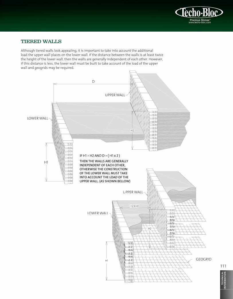
TIERED WALLS
Although tiered walls look appealing, it is important to take into account the additional load the upper wall places on the lower wall. If the distance between the walls is at least twice the height of the lower wall, then the walls are generally independent of each other. However, if this distance is less, the lower wall must be built to take account of the load of the upper wall and geogrids may be required.