Generator Breaker Failure Applications - · PDF filePreviously presented at Doble Engineering...
12
Previously presented at Doble Engineering Company – 2014 International Conference of Doble Clients Generator Breaker Failure Applications Christopher Dall, Dennis Tierney Calpine Corporation ABSTRACT This paper presents several real-world case studies which prompt further consideration when determining the schemes and corresponding current detector settings on circuit breakers directly connected to generator terminals or on the high side of their respective step-up transformers. IEEE Std. C37.119-2005 Guide for Breaker Failure Protection of Power Circuit Breakers states that it is important for breaker failure current detectors to pick-up for minimum “fault current” conditions. The guide recognizes that for generators and other high-impedance power system devices there may be practically no currents for some internal fault scenarios. In these cases IEEE Std. C37.119 recommends that the breaker failure scheme be augmented with breaker position auxiliary contacts to determine correct breaker opening. IEEE Std. C37.102-2006 Guide for AC Generator Protection section on generator breaker failure protection builds upon the schemes discussed in IEEE Std. C37.119 with the use of the breaker 52a contact to augment the current detectors in the various schemes. Furthermore, IEEE Std. C37.102 discusses a modified scheme for detection of a flashover in the generator circuit breaker. The performance of different generator breaker failure schemes and their applied settings under different real-world scenarios is discussed in detail. Proposed logic schemes and calculations are discussed with the aim of designing more robust breaker failure schemes. INTRODUCTION When designing a breaker failure scheme for a high impedance grounded generator connected to the bulk electrical system there are presently two main Standards which should be considered IEEE Std C37.102 [1] and IEEE Std C37.119 [2]. The intent of this paper is to bring together the considerations from those Standards and couple them with real world situations to provide recommendations on designing more secure and reliable breaker failure protection schemes. The purpose of a breaker failure scheme is defined in [2] as backup protection in the event that a circuit breaker fails to operate properly during fault clearing. Two failure modes are identified; Failure to Trip and Failure to Clear, breaker failure schemes must be capable of detecting both instances to function satisfactorily. Failure to Trip is the scenario in which the breaker contacts do not physically open after receiving the trip command. Failure to Clear is defined as the failure to prevent current flow even though the breaker contacts have parted, e.g. incomplete opening, dielectric problems. Loss of dielectric and contact flashover are not classically defined as a breaker failure [2], however, they are very important and should be considered for generator circuit breaker applications. Some of the standard design considerations for initiating a breaker failure scheme are listed below [1, 2]: All protective relays in the generator zone should be connected to the scheme Manually opening a breaker should not initiate the scheme Current detectors should be set to operate for minimum fault currents The breaker failure of a breaker should not initiate the scheme for an adjacent breaker. The rationale is that there is more likely to be a design flaw than two simultaneous breaker failures. The simplest breaker failure scheme is designed with the intent of protecting against breaker failure during the clearance of an electrical fault and utilizes a current detector set based on the minimum prospective fault currents. This basic scheme is presented in Figure 1. Once a protective trip is issued the current flow, through the breaker, must fall below the current threshold (50BF) before the timer (62BF) times-out otherwise a breaker failure will be declared.
Transcript of Generator Breaker Failure Applications - · PDF filePreviously presented at Doble Engineering...

Previously presented at Doble Engineering Company – 2014 International Conference of Doble Clients
Generator Breaker Failure Applications
Christopher Dall, Dennis Tierney Calpine Corporation
ABSTRACT This paper presents several real-world case studies which prompt further consideration when determining the schemes and corresponding current detector settings on circuit breakers directly connected to generator terminals or on the high side of their respective step-up transformers. IEEE Std. C37.119-2005 Guide for Breaker Failure Protection of Power Circuit Breakers states that it is important for breaker failure current detectors to pick-up for minimum “fault current” conditions. The guide recognizes that for generators and other high-impedance power system devices there may be practically no currents for some internal fault scenarios. In these cases IEEE Std. C37.119 recommends that the breaker failure scheme be augmented with breaker position auxiliary contacts to determine correct breaker opening. IEEE Std. C37.102-2006 Guide for AC Generator Protection section on generator breaker failure protection builds upon the schemes discussed in IEEE Std. C37.119 with the use of the breaker 52a contact to augment the current detectors in the various schemes. Furthermore, IEEE Std. C37.102 discusses a modified scheme for detection of a flashover in the generator circuit breaker. The performance of different generator breaker failure schemes and their applied settings under different real-world scenarios is discussed in detail. Proposed logic schemes and calculations are discussed with the aim of designing more robust breaker failure schemes.
INTRODUCTION When designing a breaker failure scheme for a high impedance grounded generator connected to the bulk electrical system there are presently two main Standards which should be considered IEEE Std C37.102 [1] and IEEE Std C37.119 [2]. The intent of this paper is to bring together the considerations from those Standards and couple them with real world situations to provide recommendations on designing more secure and reliable breaker failure protection schemes. The purpose of a breaker failure scheme is defined in [2] as backup protection in the event that a circuit breaker fails to operate properly during fault clearing. Two failure modes are identified; Failure to Trip and Failure to Clear, breaker failure schemes must be capable of detecting both instances to function satisfactorily. Failure to Trip is the scenario in which the breaker contacts do not physically open after receiving the trip command. Failure to Clear is defined as the failure to prevent current flow even though the breaker contacts have parted, e.g. incomplete opening, dielectric problems. Loss of dielectric and contact flashover are not classically defined as a breaker failure [2], however, they are very important and should be considered for generator circuit breaker applications. Some of the standard design considerations for initiating a breaker failure scheme are listed below [1, 2]:
All protective relays in the generator zone should be connected to the scheme
Manually opening a breaker should not initiate the scheme
Current detectors should be set to operate for minimum fault currents
The breaker failure of a breaker should not initiate the scheme for an adjacent breaker. The rationale is that there is more likely to be a design flaw than two simultaneous breaker failures.
The simplest breaker failure scheme is designed with the intent of protecting against breaker failure during the clearance of an electrical fault and utilizes a current detector set based on the minimum prospective fault currents. This basic scheme is presented in Figure 1. Once a protective trip is issued the current flow, through the breaker, must fall below the current threshold (50BF) before the timer (62BF) times-out otherwise a breaker failure will be declared.

2-12
50BF
BFI
Current Detector
Generation Protective Trip Breaker Failure Initiate
62BF
BFT
Breaker Failure Timer
Breaker Failure Trip
Basic breaker failure scheme
Figure 1
Circuit breakers used to protect generating units only represent a fraction of the total in-service breakers. IEEE Std C37.119 acknowledges that the guidelines are primarily aimed at breaker failure schemes on utility transmission systems as opposed to high impedance power systems such as generating stations. For circuit breakers protecting generating units, it is proposed to augment the basic scheme with a breaker position contact due to the very low current levels which may be present for some internal faults in generators or transformers. The revised scheme which incorporates breaker status is presented in Figure 2. With this scheme once the trip is issued the current must fall below the current threshold, and the breaker contacts must open before the timer (62BF) times-out otherwise a breaker failure will be declared.
50BF
52a
BFI
Current Detector
Breaker Closed
Generation Protective Trip Breaker Failure Initiate
62BF
BFT
Breaker Failure Timer
Breaker Failure Trip
Minimum fault current scheme Figure 2
For generator circuit breaker (GCB) applications the concept of incorporating flashover protection into the breaker failure scheme is presented in [1]. Typically a generator step-up transformer (GSU) is Y-d connected, and when a flashover occurs in one or two poles of the high-side circuit breaker there will be a resultant neutral current in the GSU. With this scheme, if the breaker failure initiate signal is dropped-out and subsequently there is a flashover, then the current detectors in the GSU X0 bushing and the open breaker status will reinstate the BFI signal. Following the flashover and detection by the GSU X0 current detector so long as the current flow through the breaker is greater than the 50BF phase current detectors then a breaker failure will be declared.
3-12
52b
50G
BFI
52a
50BF
62
BFT
Breaker open
GSU XO Bushing Current Detector
Generation Protective Trip Breaker Failure Initiate
Breaker Closed
Current Detector
Breaker Failure Timer
Breaker Failure Trip
Modified breaker failure for open breaker flashover detection
Figure 3
GENERATOR BREAKER FAILURE CASE STUDIES The following sections of this paper present further breaker failure scheme considerations based on real world events.
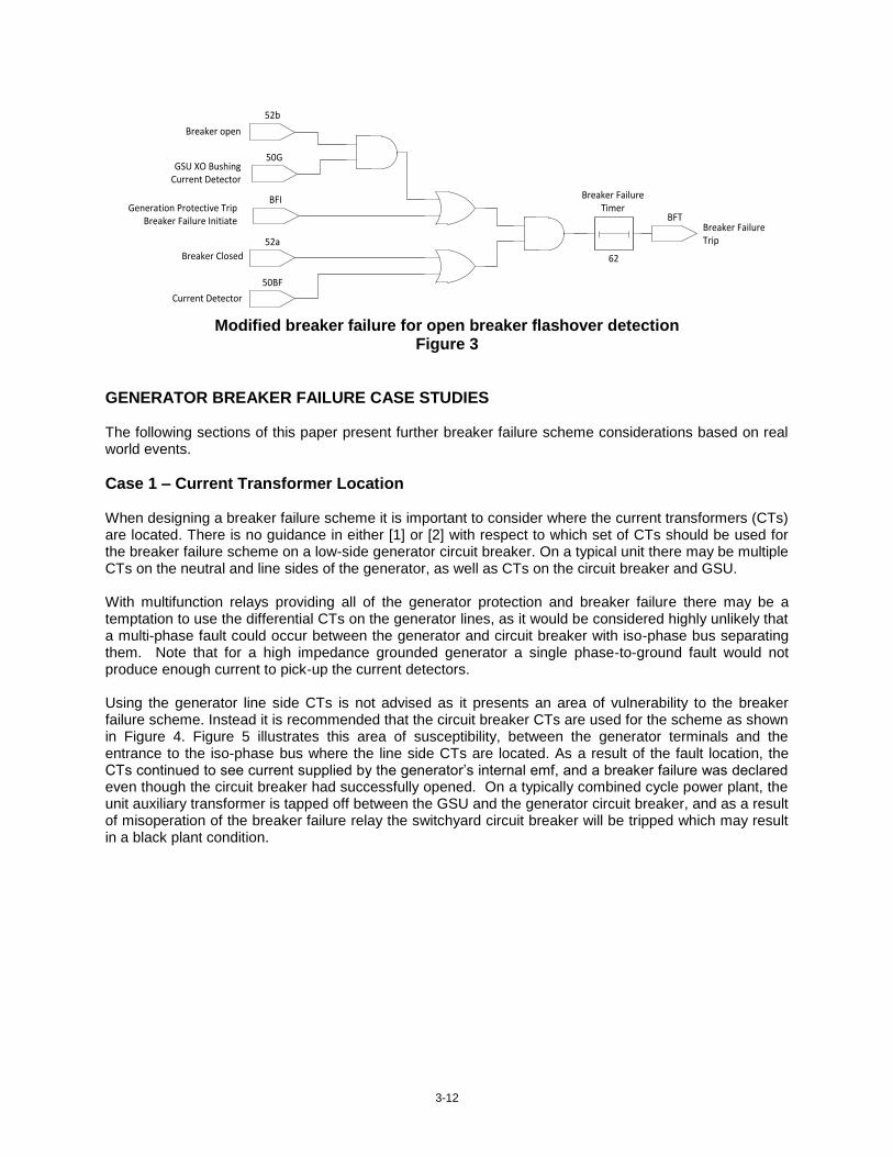
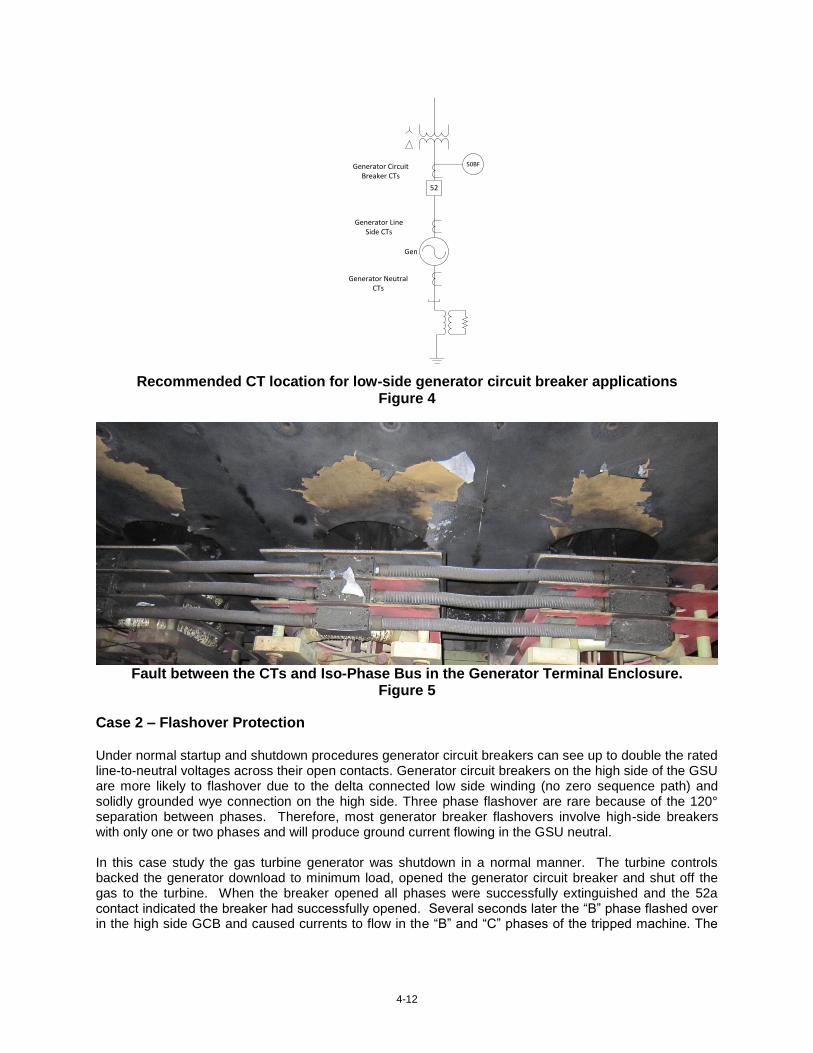
Case 1 – Current Transformer Location When designing a breaker failure scheme it is important to consider where the current transformers (CTs) are located. There is no guidance in either [1] or [2] with respect to which set of CTs should be used for the breaker failure scheme on a low-side generator circuit breaker. On a typical unit there may be multiple CTs on the neutral and line sides of the generator, as well as CTs on the circuit breaker and GSU. With multifunction relays providing all of the generator protection and breaker failure there may be a temptation to use the differential CTs on the generator lines, as it would be considered highly unlikely that a multi-phase fault could occur between the generator and circuit breaker with iso-phase bus separating them. Note that for a high impedance grounded generator a single phase-to-ground fault would not produce enough current to pick-up the current detectors. Using the generator line side CTs is not advised as it presents an area of vulnerability to the breaker failure scheme. Instead it is recommended that the circuit breaker CTs are used for the scheme as shown in Figure 4. Figure 5 illustrates this area of susceptibility, between the generator terminals and the entrance to the iso-phase bus where the line side CTs are located. As a result of the fault location, the CTs continued to see current supplied by the generator’s internal emf, and a breaker failure was declared even though the circuit breaker had successfully opened. On a typically combined cycle power plant, the unit auxiliary transformer is tapped off between the GSU and the generator circuit breaker, and as a result of misoperation of the breaker failure relay the switchyard circuit breaker will be tripped which may result in a black plant condition.
4-12
Gen
52
Generator Line Side CTs
Generator NeutralCTs
50BFGenerator Circuit Breaker CTs
Recommended CT location for low-side generator circuit breaker applications
Figure 4
Fault between the CTs and Iso-Phase Bus in the Generator Terminal Enclosure.
Figure 5
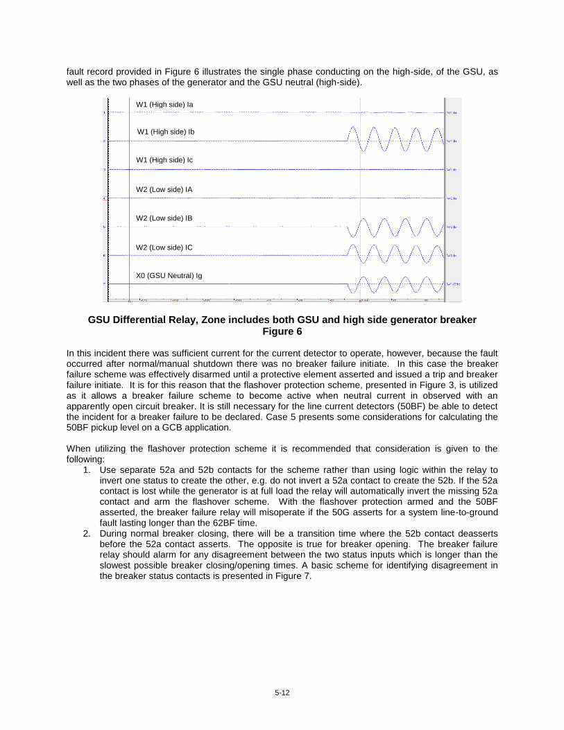
Case 2 – Flashover Protection Under normal startup and shutdown procedures generator circuit breakers can see up to double the rated line-to-neutral voltages across their open contacts. Generator circuit breakers on the high side of the GSU are more likely to flashover due to the delta connected low side winding (no zero sequence path) and solidly grounded wye connection on the high side. Three phase flashover are rare because of the 120° separation between phases. Therefore, most generator breaker flashovers involve high-side breakers with only one or two phases and will produce ground current flowing in the GSU neutral. In this case study the gas turbine generator was shutdown in a normal manner. The turbine controls backed the generator download to minimum load, opened the generator circuit breaker and shut off the gas to the turbine. When the breaker opened all phases were successfully extinguished and the 52a contact indicated the breaker had successfully opened. Several seconds later the “B” phase flashed over in the high side GCB and caused currents to flow in the “B” and “C” phases of the tripped machine. The
5-12
fault record provided in Figure 6 illustrates the single phase conducting on the high-side, of the GSU, as well as the two phases of the generator and the GSU neutral (high-side).
GSU Differential Relay, Zone includes both GSU and high side generator breaker Figure 6
In this incident there was sufficient current for the current detector to operate, however, because the fault occurred after normal/manual shutdown there was no breaker failure initiate. In this case the breaker failure scheme was effectively disarmed until a protective element asserted and issued a trip and breaker failure initiate. It is for this reason that the flashover protection scheme, presented in Figure 3, is utilized as it allows a breaker failure scheme to become active when neutral current in observed with an apparently open circuit breaker. It is still necessary for the line current detectors (50BF) be able to detect the incident for a breaker failure to be declared. Case 5 presents some considerations for calculating the 50BF pickup level on a GCB application. When utilizing the flashover protection scheme it is recommended that consideration is given to the following:
1. Use separate 52a and 52b contacts for the scheme rather than using logic within the relay to invert one status to create the other, e.g. do not invert a 52a contact to create the 52b. If the 52a contact is lost while the generator is at full load the relay will automatically invert the missing 52a contact and arm the flashover scheme. With the flashover protection armed and the 50BF asserted, the breaker failure relay will misoperate if the 50G asserts for a system line-to-ground fault lasting longer than the 62BF time.
2. During normal breaker closing, there will be a transition time where the 52b contact deasserts before the 52a contact asserts. The opposite is true for breaker opening. The breaker failure relay should alarm for any disagreement between the two status inputs which is longer than the slowest possible breaker closing/opening times. A basic scheme for identifying disagreement in the breaker status contacts is presented in Figure 7.
W1 (High side) Ia
W2 (Low side) IA
X0 (GSU Neutral) Ig
W2 (Low side) IC
W2 (Low side) IB
W1 (High side) Ib
W1 (High side) Ic

6-12
73D
62D
52b
52a
Breaker open
Breaker Closed
52a/b Disagreement
Breaker status disagreement scheme
Figure 7
3. Special attention should be paid to the flashover protection scheme if the GSU is connected into a ring bus or a breaker and a half scheme. In this case the flashover protection scheme should only be alarmed if both breakers feeding the GSU are open. The 52b contacts from both breakers must be connected to the breaker failure relays using the GSU X0 current detectors. The flashover protection scheme in each relay should only be alarmed when both breakers’ 52b contacts are asserted. The use of both 52b contacts adds to the security of the scheme and also prevents the scheme from arming for a system fault.
Case 3 – Noise on BFI Signal Breaker failure schemes which latch the breaker failure initiate signal or issue an instantaneous re-trip are susceptible to noise on the DC circuitry. Figure 8 illustrates an undesired transient on the BFI input to a generator high-side breaker. The result of this ¼ cycle transient on the breaker fail initiate signal was the loss of the high voltage switchyard and the multiple generating units connected to it. The breaker failure scheme which had been utilized to protect this circuit breaker immediately latched in the BFI signal and due to the 52a contact and 50BF being asserted a breaker failure was declared.
Breaker Failure Relay Noise
Figure 8
For breaker failure schemes which latch in the breaker failure initiate signal or utilize an instantaneous re-trip function it is important to use a timer on the BFI input to filter out noise and prevent an inadvertent trip
7-12
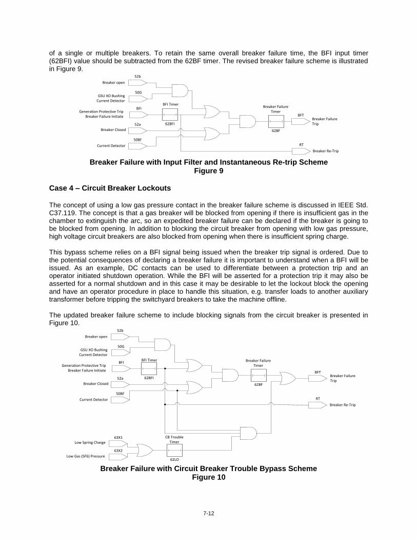
of a single or multiple breakers. To retain the same overall breaker failure time, the BFI input timer (62BFI) value should be subtracted from the 62BF timer. The revised breaker failure scheme is illustrated in Figure 9.
52b
50G
BFI
52a
50BF
62BF
BFT
Breaker open
GSU XO Bushing Current Detector
Generation Protective Trip Breaker Failure Initiate
Breaker Closed
Current Detector
Breaker Failure Timer
Breaker Failure Trip62BFI
RT
Breaker Re-Trip
BFI Timer
Breaker Failure with Input Filter and Instantaneous Re-trip Scheme
Figure 9 Case 4 – Circuit Breaker Lockouts The concept of using a low gas pressure contact in the breaker failure scheme is discussed in IEEE Std. C37.119. The concept is that a gas breaker will be blocked from opening if there is insufficient gas in the chamber to extinguish the arc, so an expedited breaker failure can be declared if the breaker is going to be blocked from opening. In addition to blocking the circuit breaker from opening with low gas pressure, high voltage circuit breakers are also blocked from opening when there is insufficient spring charge. This bypass scheme relies on a BFI signal being issued when the breaker trip signal is ordered. Due to the potential consequences of declaring a breaker failure it is important to understand when a BFI will be issued. As an example, DC contacts can be used to differentiate between a protection trip and an operator initiated shutdown operation. While the BFI will be asserted for a protection trip it may also be asserted for a normal shutdown and in this case it may be desirable to let the lockout block the opening and have an operator procedure in place to handle this situation, e.g. transfer loads to another auxiliary transformer before tripping the switchyard breakers to take the machine offline. The updated breaker failure scheme to include blocking signals from the circuit breaker is presented in Figure 10.
52b
50G
BFI
52a
50BF
62BF
BFT
Breaker open
GSU XO Bushing Current Detector
Generation Protective Trip Breaker Failure Initiate
Breaker Closed
Current Detector
Breaker Failure Timer
Breaker Failure Trip
62BFI
RT
Breaker Re-Trip
BFI Timer
63X1
63X2
Low Spring Charge
Low Gas (SF6) Pressure62LO
CB TroubleTimer
Breaker Failure with Circuit Breaker Trouble Bypass Scheme
Figure 10

8-12
Case 5 – Current Detectors The selection of the breaker failure current detector is discussed in IEEE Std. C37.119 where it recommends that the pickup should be capable of detecting minimum “fault current conditions”. It also notes that for high-impedance equipment such as generators and transformers the only practical method of detecting a failed breaker opening may be through the use of the 52a contact due to the very low currents associated with “internal faults”. When a flashover occurs or a mechanical linkage breaks and the current continues to flow in one or more phases of the generator circuit breaker, typically the 52a contact will indicate that the circuit breaker is open. It is therefore necessary to be able to detect the failed breaker with the current detector. Setting the current detectors based on prospective fault currents and relying on the 52a contact for low current events leaves the generator vulnerable to motoring events. Motoring the generator has the potential to cause significant damage to the machine. Shortly after synchronizing a generator a protective trip was ordered, taking the exciter and turbine offline as well as tripping the generator high-side circuit breaker. In this case two of the poles on the breaker continued to conduct which motored the machine with unbalanced currents in all three phases. The fault record captured by the GSU differential relay is shown in Figure 11.
I N 1 0 1
T R I P 1
O U T 1 0 1
- 5
0
5
- 2 .5
0 .0
2 .5
0 .0 2 .5 5 .0 7 .5 1 0 .0 1 2 .5 1 5 .0
IA
W1
I
BW
1
IC
W1
IA
W2
I
BW
2
IC
W2
Dig
ita
ls
C y c le s
IA W 1 IB W 1 IC W 1 IA W 2 IB W 2 IC W 2
Two Phase Flashover in High Side Generator Circuit Breaker
Figure 11
In this scenario the current detector scheme employed was set based on the prospective fault currents in the switchyard (>10 kA). For a Frame 7 gas turbine generator the motoring currents observed at the generator terminals was in the range of 3-4.5 kA which equated to 650 A in the high-side breaker. When selecting a suitable current detector level it is recommended that the prospective motoring currents are considered. As an example, for a two phase flashover on the high-side of a GSU (assuming Wye-delta connected) there will be unbalanced three phase currents on the machine and neutral current in the GSU X0 bushing. Using sequence networks and the readily available parameters for the generator, GSU and system the line and neutral currents can be determined on both sides of the GSU [3]. Figure 12 below illustrates the simplified sequence network for a two pole flashover on the high-side of a GSU.

9-12
I2
I0
I1
Es Eg
ZtrZ1sys
Z2sys
Z0sys
Xd
X2Ztr
Z0tr
Where: Xd – generator synchronous reactance
X2 – generator negative sequence reactance
Ztr – transformer positive sequence impedance
Z0tr – transformer zero sequence impedance
Z1sys – Positive sequence Thevenin equivalent impedance
Z0sys – Zero sequence Thevenin equivalent impedance
Es – System voltage
Eg – Generator voltage
I1, I2, I0 – Positive, Negative and Zero Sequence Currents
GSU High Side Currents:
GSU Low Side Currents:
GSU Neutral Current (X0 bushing):
Ibsys – base current on system voltage Ibgen – base current on generator voltage
Simplified Sequence Network for Two Pole Flashover
Figure 12
Case 6 – Breaker Failure with Exciter Online
There are instances of generator breaker failures where the current magnitudes involved are practically undetectable on the high-side of a GSU however, it may be possible to detect these events using unconventional breaker failure schemes in existing protection equipment. In Case 5 the exciter was offline when the machine was tripped with virtually no-load and the subsequent motoring currents where of sufficient magnitude that they could be detected by the CTs on the high-side of the generator step-up transformer. With certain machines it is common to leave the exciter online until the speed of the machine has reached a given set-point (e.g. 95% of nominal). Figure 13 and 14 illustrate the currents observed at the HV and LV side of the GSU for two breaker failures where the exciters remained online. In both cases it is apparent that while the exciter is online the current magnitudes on the HV side are significantly below minimum pickup values of the breaker failure relays. The significant increase in current associated with the exciter tripping is evident in Figure 13.

10-12
GCB Trip Signal Exciter Tripped SWYD CB Opens
0
50
100
150
200
250
300
350
0
500
1000
1500
2000
2500
3000
3500
4000
Cu
rre
nt
(re
ferr
ed
to
34
5 k
V)
Cu
rre
nt
(re
ferr
ed
to
18
kV
)
Time
A (18 kV @gen)A (345 kV @SWYD)Min. 50BF Pickup
GCB Trip Signal SWYD CB Opens
0
25
50
75
100
125
0
500
1000
1500
2000
2500
Cu
rre
nt
(re
ferr
ed
to
34
5 k
V)
Cu
rre
nt
(re
ferr
ed
to
18
kV
)
Time
A (18 kV @gen)
A (345 kV @SWYD)
Min 50BF Pickup
Exciter Online - Event 1 Current Magnitudes
Figure 13 Exciter Online - Event 2 Current Magnitudes
Figure 14
While both of these instances were undetectable by the 50BF on the high-side breakers the generator protection relays (GPR) picked-up for reverse power. Figure 15 and 16 illustrate the real and reactive power recorded by the plant DCS with the GPR reverse power pickup superimposed. In both events it is clear that even with the exciter online the motoring currents drawn by the generator are easily detectable by the GPR. A simplified proposed scheme that would bypass the conventional breaker failure scheme is presented in Figure 17. The basic concept behind this scheme is that when the generator circuit breaker status is open and there is no disagreement so long as the LCI start is not active then the reverse power element in the generator protection can be used to identify a breaker failure. For generators which are started via LCI drives it is important to disarm this protection in that scenario. This is an area which Calpine will be further investigating to determine the suitability of implementing this type of breaker failure protection.
GCB Trip Signal Exciter Tripped SWYD CB Opens
-60
-40
-20
0
20
40
60
Ge
ne
rato
r M
W/M
VA
r
Time
MWMVArRev. Power (MW) Pickup
GCB Trip Signal
SWYD CB Opens
-10
-5
0
5
10
15
20
25
30
Ge
ne
rato
r M
W/M
VA
r
Time
MWMVArRev. Power (MW) PU
Exciter Online - Event 1 Real/Reactive Power
Figure 15 Exciter Online - Event 2 Real/Reactive Power
Figure 16

11-12
52b
50G
BFI
52a
50BF
62BF
BFT
Breaker open
GSU XO Bushing Current Detector
Generation Protective Trip Breaker Failure Initiate
Breaker Closed
Current Detector
Breaker Failure Timer
Breaker Failure Trip62BFI
RT
Breaker Re-Trip
BFI Timer
63X1
63X2
Low Spring Charge
Low Gas (SF6) Pressure62LO
CB TroubleTimer
32GPR Reverse
Power62RP
Reverse Power TimerLCI Start
52a/b Disagreement
Breaker Failure with Reverse Power Bypass Scheme
Figure 17
CONCLUSION This paper provides practical guidance on the application of breaker failure schemes for generator circuit breakers. The paper uses real world incidents to expand upon the commonly applied schemes and provides additional considerations when designing breaker failure schemes for generator applications. When determining current detector levels for generator circuit breaker schemes it is recommended that the prospective motoring currents are calculated to determine the appropriate line and neutral pickup values. Several incidents have highlighted the opportunity for breaker failure incidents to go unnoticed when the exciter remains online following the circuit breaker trip. This is an area in which further investigating is required to determine the viability of the proposed scheme in a real world situation. At this time no breaker failure scheme is fool proof and it is recommended that power plant operators have procedures in place to minimize the impact of a failed generator breaker.
REFERENCES
[1] IEEE Std C37.102, “IEEE Guide for AC Generator Protection”, IEEE, 2006 [2] IEEE Std C37.119, “IEEE Guide For Breaker Failure Protection Of Power Circuit Breakers”, IEEE, 2005 [3] Reimert, D., “Protective Relaying for Power Generation Systems”, Taylor & Francis, Boca Raton, 2006
12-12
BIOGRAPHY Christopher Dall received his Master of Engineering degree in Electrical and Electronic Engineering from Heriot Watt University, Edinburgh, UK. After graduating, Mr. Dall worked for an international consultancy providing power systems analysis services primarily for the oil and gas sector. He is presently employed at Calpine Corporation as a Senior Electrical Engineer supporting their fleet of operational power plants across the United States. Mr. Dall is a registered Professional Engineer in Texas and a Chartered Engineer, UK. Dennis Tierney is currently working for Calpine Corp. in Houston Texas where he provides electrical engineering support for Calpine’s 92 operational power plants located across the United States. Before working at Calpine Corporation, Dennis worked for Mott MacDonald Group where he provided field engineering design and support for two new power plants in Shuwaikh and Sabiya Kuwait. Dennis worked as a Senior Applications Engineer for Relay Protection at Doble Engineering Company for approximately 10 years. Prior to this position, for eleven years, Dennis worked at Salt River Project in Phoenix, Arizona, in system protection, power quality and SCADA. Before working at the Salt River Project, he worked in HVDC and Communications at the Los Angeles Department of Water and Power. Dennis graduated from Arizona State University in 1982 with a Bachelors of Science Degree in Electrical Engineering.