GENERATOR AND MOTOR COMMANDER™ - … GENERATOR AND MOTOR COMMANDER is a unique innovation...
8
GENERATOR AND MOTOR COMMANDER™ CONTROL & PROTECTION IN ONE PACKAGE
Transcript of GENERATOR AND MOTOR COMMANDER™ - … GENERATOR AND MOTOR COMMANDER is a unique innovation...

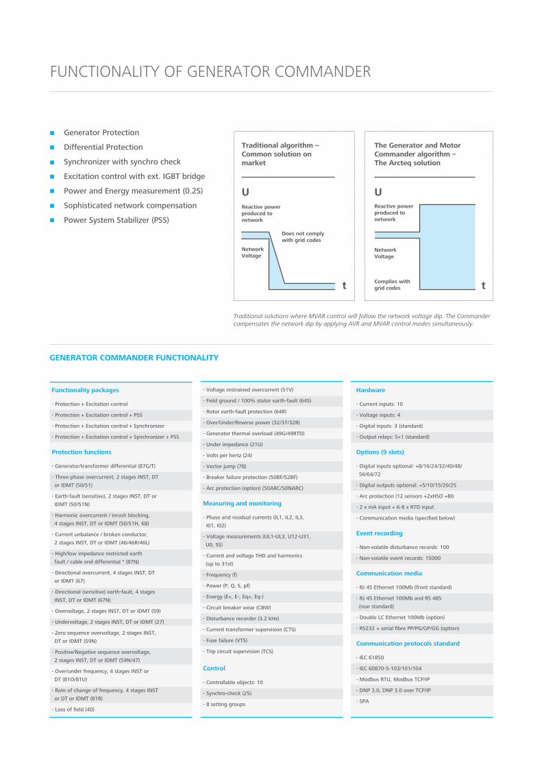
GENERATOR ANDMOTOR COMMANDER™CONTROL & PROTECTION IN ONE PACKAGE

THE GENERATOR AND MOTOR COMMANDER is a unique innovation combining machine protection and
control into one unit. The Commander is ideal for any power plant or industrial application where both
protection and control of generators or motors is needed.
Compared to traditional systems with several separate units and software, the Commander takes less space
and saves considerable hours of engineering time. Operation is smooth as there is only one interface to the
system.
The Commander is based on powerful AQ 200 series IED technology. AQ 200 is the most accurate protec-
tion and control IED on the market. The signature features include ultra accurate measurement and protec-
tion, high performance logic, high resolution disturbance recording and all non-volatile memory.
BENEFITSUp to 40 % savings in time & cost for installation and commissioning
Reduced maintenance and life cycle cost. Only two spareparts needed for the whole system
Up to 86% space saving
Easy to duplicate for redundancy
One tool, one interface to all functionality
Software wizards for automatic setting calculations
GENERATOR AND MOTOR COMMANDER
EXCLUSIVE FEATURES
For 1 - 250 MW brushless synchronous generators and motors
Sophisticated network compensation and Power System Stabilizerincluded → Complies with most rigorous grid codes
Versatile motor start-up sequences
Synchronizer and synchrocheck features for safe power grid connection
Unique 0.2S measurement accuracy
•
•
•
•
•
Traditional machine protection and controlrequiring up to 6 separate units.
ALL IN ONE
The Generator andMotor Commanderdoes the same job
with one unit.
Excitation
Synchronizer
Synchrocheck
Machine protection
Differential protection
Power Monitoring Unit
Power Monitoring Unit
Synchronizer
Synchrocheck DifferentialprotectionMachine
protection
Excitation
In the past all systems and even single protection functions were divided to separate units.
1 3 4 5 62
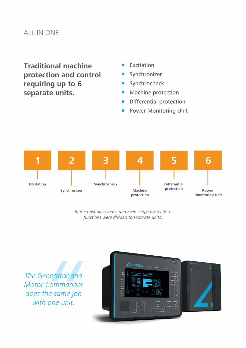
Traditional solutions where MVAR control will follow the network voltage dip. The Commander compensates the network dip by applying AVR and MVAR control modes simultaneously.
FUNCTIONALITY OF GENERATOR COMMANDER
GENERATOR COMMANDER FUNCTIONALITY
Generator Protection
Differential Protection
Synchronizer with synchro check
Excitation control with ext. IGBT bridge
Power and Energy measurement (0.2S)
Sophisticated network compensation
Power System Stabilizer (PSS)
Functionality packages
- Protection + Excitation control
- Protection + Excitation control + PSS
- Protection + Excitation control + Synchronizer
- Protection + Excitation control + Synchronizer + PSS
Protection functions
- Generator/transformer differential (87G/T)
- Three-phase overcurrent, 2 stages INST, DT
or IDMT (50/51)
- Earth-fault (sensitive), 2 stages INST, DT or
IDMT (50/51N)
- Harmonic overcurrent / inrush blocking,
4 stages INST, DT or IDMT (50/51H, 68)
- Current unbalance / broken conductor,
2 stages INST, DT or IDMT (46/46R/46L)
- High/low impedance restricted earth
fault / cable end differential * (87N)
- Directional overcurrent, 4 stages INST, DT
or IDMT (67)
- Directional (sensitive) earth-fault, 4 stages
INST, DT or IDMT (67N)
- Overvoltage, 2 stages INST, DT or IDMT (59)
- Undervoltage, 2 stages INST, DT or IDMT (27)
- Zero sequence overvoltage, 2 stages INST,
DT or IDMT (59N)
- Positive/Negative sequence overvoltage,
2 stages INST, DT or IDMT (59N/47)
- Over/under frequency, 4 stages INST or
DT (81O/81U)
- Rate of change of frequency, 4 stages INST
or DT or IDMT (81R)
- Loss of field (40)
- Voltage restrained overcurrent (51V)
- Field ground / 100% stator earth-fault (64S)
- Rotor earth-fault protection (64R)
- Over/Under/Reverse power (32/37/32R)
- Generator thermal overload (49G/49RTD)
- Under impedance (21U)
- Volts per hertz (24)
- Vector jump (78)
- Breaker failure protection (50BF/52BF)
- Arc protection (option) (50ARC/50NARC)
Measuring and monitoring
- Phase and residual currents (IL1, IL2, IL3,
I01, I02)
- Voltage measurements (UL1-UL3, U12-U31,
U0, SS)
- Current and voltage THD and harmonics
(up to 31st)
- Frequency (f)
- Power (P, Q, S, pf)
- Energy (E+, E-, Eq+, Eq-)
- Circuit breaker wear (CBW)
- Disturbance recorder (3.2 kHz)
- Current transformer supervision (CTS)
- Fuse failure (VTS)
- Trip circuit supervision (TCS)
Control
- Controllable objects: 10
- Synchro-check (25)
- 8 setting groups
Hardware
- Current inputs: 10
- Voltage inputs: 4
- Digital inputs: 3 (standard)
- Output relays: 5+1 (standard)
Options (9 slots)
- Digital inputs optional: +8/16/24/32/40/48/
56/64/72
- Digital outputs optional: +5/10/15/20/25
- Arc protection (12 sensors +2xHSO +BI)
- 2 x mA input + 6-8 x RTD input
- Communication media (specified below)
Event recording
- Non-volatile disturbance records: 100
- Non-volatile event records: 15000
Communication media
- RJ 45 Ethernet 100Mb (front standard)
- RJ 45 Ethernet 100Mb and RS 485
(rear standard)
- Double LC Ethernet 100Mb (option)
- RS232 + serial fibre PP/PG/GP/GG (option)
Communication protocols standard
- IEC 61850
- IEC 60870-5-103/101/104
- Modbus RTU, Modbus TCP/IP
- DNP 3.0, DNP 3.0 over TCP/IP
- SPA
Does not comply with grid codes
Reactive powerproduced tonetwork
Complies with grid codes
Traditional algorithm –Common solution on market
The Generator and MotorCommander algorithm –The Arcteq solution
Reactive power produced to network
Network Voltage
Network Voltage
UU
tt

GENERATOR COMMANDER APPLICATION
G
AQ-G257 Generator protection and control IED
IEC61850
UL12
, UL23
U0
I01
I02
IL1, I
L2, I
L3
I0>
I0>>
Z<21U
U0>
U0>>
59N
Meas0.2S
Id>87G/T
X<40I>I>>
50/51
AQ-GC30 Exciter unit
Excitation
AVRAutomatic
voltage regulator
CosF ctrl Cosφ control
(PF ctrl)
SCL Stator current
limiter
FCRField current
regulator
Diode failure monitoring
UELUnderexcitation
limiter
Qctrl Reactive power
(Q) control
OEL Overexcitation
limiter
Frequency
Synchronizer
Voltage Phase angle
I0Dir>
I0Dir>>67N
IDir>IDir>>
67
AVRFCR
Excitation
90
Synchronizer
V/∫/ f
25
Synchrocheck
V/∫/ f
25
df/dt
81R
Ursd>/U2>
59N/47
Ixh>Ixh>>
50/51H68
I2>
I2>>
46/46R/46L
U<U<<
27U>U>>
59f<, f<</f>, f>>
81O/81U
87N I0d>
78 OOS
64S I0>
50BF/52BF
CBFP
50ARC/
50NARCARC
64R I0>49G/
49RTDT>
I>/U<51VQ<24
32/37/32R
P>/P>>/P
50/51N
2 2 4 4
2 2
2 4
2 2
4 4
AQ 200 SERIES PLATFORM FEATURES
7" color display
16 freely configurable alarm leds and 12 function buttons
10 controllable objects
IEC 61850 + extensive set of legacy protocols
•
•
•
•

MOTOR COMMANDER FUNCTIONALITY
FUNCTIONALITY OF MOTOR COMMANDER
Motor Protection
Differential Protection
Startup sequence control
Excitation with ext. IGBT bridge
Power and Energy measurement (0.2S)
FLEXIBLE START-UP SEQUENCE
Functionality packages
- Synchronous motor protection & Excitation control
Protection functions
- Motor differential (87M)
- Three-phase overcurrent, 4 stages INST, DT or
IDMT (50/51)
- Earth-fault (sensitive), 4 stages INST, DT or
IDMT (50/51N)
- Directional overcurrent, 4 stages INST, DT or IDMT (67)
- Directional (sensitive) earth-fault, 4 stages
INST, DT or IDMT (67N)
- Harmonic overcurrent / inrush blocking,
4 stages INST, DT or IDMT (50/51H, 68)
- Current unbalance / broken conductor,
4 stages INST, DT or IDMT (46/46R/46L)
- Cable end differential (87N)
- Motor thermal overload (49M)
- Motor start-up / locked rotor supervision with
speed switch (48,14)
- Restart inhibit / frequent starts (66/86)
- Undercurrent/loss of load (37)
- Power factor protection (55)
- Mechanical jam (51M)
- Loss of field (40)
- Overvoltage, 4 stages INST, DT or IDMT (59)
- Undervoltage, 4 stages INST, DT or IDMT (27)
- Zero sequence overvoltage, 4 stages INST,
DT or IDMT (59N)
- Negative/positive sequence overvoltage,
4 stages INST, DT or IDMT (47)
- Over/under frequency, 8 stages INST or
DT (81O/81U)
- Over/Under/Reverse power (32/37/32R)
- Breaker failure protection (50BF/52BF)
- Arc protection (optional) (50ARC/50NARC)
Measuring and monitoring
- Phase and residual currents (IL1, IL2, IL3, I01, I02)
- Voltage measurements (UL1-UL3, U12-U31, U0, SS)
- Current and voltage THD and harmonics
(up to 31st)
- Frequency (f)
- Power (P, Q, S, pf)
- Energy (E+, E-, Eq+, Eq-)
- Circuit breaker wear (CBW)
- Disturbance recorder (3.2 kHz)
- Current transformer supervision (CTS)
- Fuse failure (VTS)
- Trip circuit supervision (TCS)
Control
- Controllable objects: 10
- 8 setting groups
Hardware
- Current inputs: 10
- Voltage inputs: 4
- Digital inputs: 3 (standard)
- Output relays: 5+1 (standard)
Options (9 slots)
- Digital inputs optional: +8/16/24/32/40/48/56/64/72
- Digital outputs optional: +5/10/15/20/25
- Arc protection (12 sensors +2xHSO +BI)
- 2 x mA input + 6-8 x RTD input
- Communication media (specified below)
Event recording
- Non-volatile disturbance records: 100
- Non-volatile event records: 15000
Communication media
- RJ 45 Ethernet 100Mb (front standard)
- RJ 45 Ethernet 100Mb and RS 485
(rear standard)
- Double RJ 45 or LC Ethernet 100Mb (option)
- RS232 + serial fibre PP/PG/GP/GG (option)
Communication protocols standard
- IEC 61850
- IEC 60870-5-103/101/104
- Modbus RTU, Modbus TCP/IP
- DNP 3.0, DNP 3.0 over TCP/IP
- SPA
M MM
Start-up withTransformer
Direct start-up sequence
Start-up with reactor

M
AQ-M257 Motor protection and control IED
IEC61850
UL12
, UL23
U0
I01
I02 I
0>
I0>>
Im>51m
U0>
U0>>
59N
Meas0.2S
Id>87M
cosf>55I>I>>
50/51
AQ-GC30 Exciter unit
Excitation
AVRAutomatic
voltage regulator
CosF ctrl Cosφ control
(PF ctrl)
SCL Stator current
limiter
FCRField current
regulator
Diode failure monitoring
UELUnderexcitation
limiter
Qctrl Reactive power
(Q) control
OEL Overexcitation
limiter
Reactor start
Start-up sequence control
Auto trafo Direct start
I0Dir>
I0Dir>>67N
AVRFCR
Excitation
90
Synchrocheck
V/∫/ f
25
df/dt
81R
Ursd>/U2>
59N/47
Ixh>Ixh>>
50/51H68
I2>
I2>>
46/46R/46L
U<U<<
27U>U>>
59f<, f<</f>, f>>
81O/81U
87N I0d>
37 I<
64S I0>
50BF/52BF
CBFP
50ARC/
50NARCARC
64R I0>49M/
49RTDT>
ISt>14
N>66
32/37/32R
P>/P>>/P
50/51N
2 2 4 4
2 2
2 4
2 2
4
IL1, I
L2, I
L3
IL1 I
L2 I
L3
AutoTrafo start
Reactorstart
X<40
MOTOR COMMANDER APPLICATION
AQ 200 SERIES PLATFORM FEATURES
100 disturbance records in non volatile memory
64 samples per cycle sampling rate (3.2 kHz)
Instant protection operation time typically 15ms
Freely programmable and advanced logic performed in 5ms cycles
•
•
•
•
HEADQUARTERSArcteq Relays LtdWolffintie 36 F 1265200 Vaasa, Finlandtel: +358 10 3221 370fax. +358 10 3221 389
EMAIL INQUIRIES:[email protected]
EMAIL TECHNICAL SUPPORT: [email protected] line (EET 8am - 4pm)+358 10 3221 388