General Procedures - CI STRUCTURES · SPRUNG INSTANT STRUCTURES Toll Free: 1 800.661.1163 mitch.cam...
11
SPRUNG INSTANT STRUCTURES Toll Free: 1 800.661.1163 [email protected] www.sprung.com General Procedures Signature Series Edition The following document outlines the key principles used in erecting the Sprung Instant Structure. It is to be used in conjunction with the manpower & equipment guide provided by our Contracts department. This document is in no way a definitive guide to the erection of a Sprung Instant Structure. The construction of a Sprung Instant Structure can be categorized into seven distinct operations. These are: 1. Layout & Assembly 2. Erect Frame 3. Installing Membrane Panels 4. Optional Insulation Package 5. Tension & Anchor 6. Close end 7. Options The following pages will give you a basic idea of what is entailed for each general procedure. Equipment recommendations are listed for each operation. Refer to the appendix for notes regarding the specifics of the equipment.
Transcript of General Procedures - CI STRUCTURES · SPRUNG INSTANT STRUCTURES Toll Free: 1 800.661.1163 mitch.cam...

SPRUNG INSTANT STRUCTURES
Toll Free: 1 800.661.1163 [email protected] www.sprung.com
General ProceduresSignature Series Edition
The following document outlines the key principles used in erecting the Sprung InstantStructure. It is to be used in conjunction with the manpower & equipment guide provided by ourContracts department. This document is in no way a definitive guide to the erection of a SprungInstant Structure.
The construction of a Sprung Instant Structure can be categorized into seven distinctoperations. These are:
1. Layout & Assembly2. Erect Frame3. Installing Membrane Panels4. Optional Insulation Package5. Tension & Anchor6. Close end7. Options
The following pages will give you a basic idea of what is entailed for each generalprocedure. Equipment recommendations are listed for each operation. Refer to the appendix fornotes regarding the specifics of the equipment.

Layout & Assembly
Bundled and crated components to be distributed around the job site in appropriate areas.
The aluminum beams, which form the substructure, will arrive on site in a condensed manner. These beams will be moved into position, one at a time, on to the pad where the structure is to beerected. They will be staged in a specific pattern which facilitates their assembly and subsequenterection with a crane. The crated components comprise all the smaller materials used toassemble the beams. Splice plates, fasteners, and base assemblies are all located amongst thecrated materials. These will be used to assemble the individual beams into arches. Dunnage(wooden blocks) should be placed under the beams to ease the assembly operation.
Typical equipment required:Forklift DunnageElectric powerHand Tools
This graphic (right)
depicts the layout
pattern generally used.
This graphic (left) depicts a
typical Center arch.
Erecting the Substructure
This process begins with the erection of the first arch. While still on the ground, nylon and wireropes are attached to this first arch in specific locations. These tie off ropes will support the firstarch. Each arch is erected using a crane. Structures 70' wide and larger require a small spreaderbar. It is recommended that only nylon straps be used for this operation to avoid damage to thealuminum arch, but the discretion lies with the company providing the crane. Position the baseof the arch into its proper location and anchor. Tighten the tie off ropes. Put a little slack intothe rigging and, using the tie off ropes, plumb the arch. On very large structures ( 100' wide andlarger ), it may be convenient to use a optical transit. Once the arch is plumb, disconnect therigging and prepare to raise the second arch.
The second arch is raised into position approximately 15' from the first arch. This arch isconnected to the first with spreaders (aluminum purlins). This second arch is then temporarilyanchored to the foundation. Move on to the next arch. Each arch is erected in the same manner.
Typical equipment required:Electric powerCrane c/w rigger 2 Manlifts Hand Tools
The aluminum substructure

Installing the Membrane
This process begins once an adequate amount of the substructure has been erected (usually 100linear feet). Each modular bay of the Sprung Structure receives one membrane panel. There aretwo main types of membrane; Center panels & End panels. These are packed rolled in thewooden crates. Each panel has a ½" nylon rope welded along the length of both edges. TheCenter panel is rectangular in shape, whereas the End panel is triangular.
Center panels are installed from the ground using an innovative procedure which involveselectric winches. Six workers are required for this operation. Two workers guide the membraneinto the integrated channel of the beam on the feeding side, two workers operate the winches onthe opposite side, while the remaining two workers monitor the process at the structures apex. These winches are attached to the beam using the integrated bolt chase. The roped edge of themembrane is inserted into the chase and fed from the ground up. Once the membrane has beeninstalled the workers then move on to the next bay. Two other workers follow behind this crewand vertically tension the membrane with a small hydraulic device (found in the Sprung ToolKit). If your Sprung Structure is insulated it is a good idea to install the insulation retentionsystem prior to installing the exterior membrane. This option is covered in the next section.
End panels are installed using the same principle. Two workers place themselves at the crown ofthe radius end on the inside. These two workers guide the membrane into the integrated channelwhile workers at the base operate the winches. End panels are typically only installed once theCenter panels are complete.
Typical equipment required:ManliftFall Arrest GearHand Tools / Winches
Close-up of the electric winch Installing the membrane
Optional Insulation Package
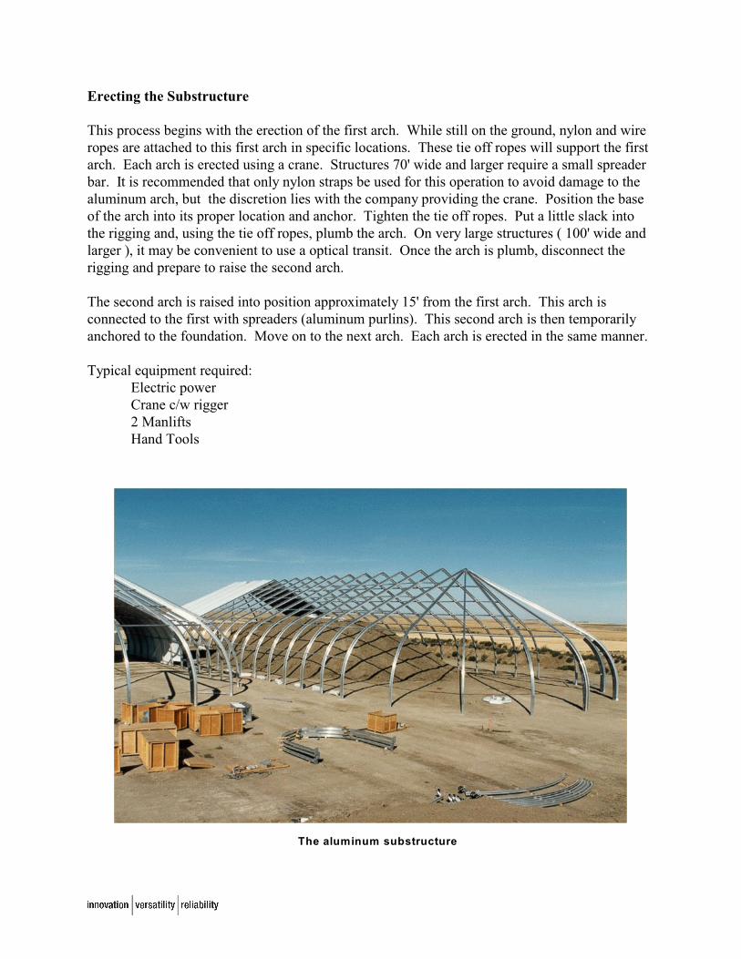
Sprung Instant Structures can be fully insulated with a Formaldehyde Free, foil backed fiberglassblanket up to 8" thick. This insulation is encapsulated between two layers of architecturalmembrane providing an aesthetically pleasing finish, inside and out.
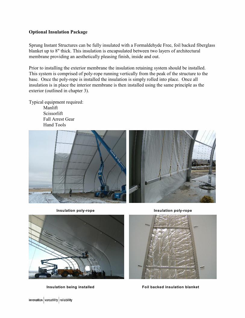
Prior to installing the exterior membrane the insulation retaining system should be installed. This system is comprised of poly-rope running vertically from the peak of the structure to thebase. Once the poly-rope is installed the insulation is simply rolled into place. Once allinsulation is in place the interior membrane is then installed using the same principle as theexterior (outlined in chapter 3).
Typical equipment required:ManliftScissorliftFall Arrest GearHand Tools
Insulation poly-rope Insulation poly-rope
Insulation being installed Foil backed insulation blanket

Tension & Anchor
The act of hydraulically tensioning the membrane.
Typically this procedure begins after the membrane has been installed into a few modular bays. The first step requires the membrane to be tensioned vertically along the roped edge. This isaccomplished by attaching a special hydraulic pump ( which is provided in Sprung’s Tool Kit ) atbase of the beam. At the same time workers are preparing the purlins on the inside of thestructure, as well as removing any temporary foundation anchors that were installed. To laterallytension each modular bay the hydraulic pumps are attached to the purlins. Each purlin istensioned approximately 5" to a predetermined point and secured by a bolt. The beams are thenanchored into their final position.
Typical equipment required:2 ManliftsFall Arrest GearHand Tools
Workers tensioning the membrane Close-up of hydraulic unit

Close End
The term “closing the end” refers to a sequence of tasks which complete the radius End module.
All the membrane panels in the End module, aside from one, are installed and tensioned. Wireropes (tirfors) are spanned across the End bay that is left open. These wire ropes are tensioneduntil the bay has collapsed enough to insert the final membrane panel. The final membrane panelis then installed and tensioned. All the end beams are then anchored, and the End module iscomplete.
Typical equipment required:2 ManliftsFall Arrest GearHand Tools
Interior view of the end being “closed” Exterior view of the end being “closed”

Options
Options can include, but not limited to, the following; hoods, vents, cargo doors, personneldoors, windows, graphics, perimeter flat bar, aircraft hanger doors, framed openings for HVAC,tunnels, lights, entrance canopies, architectural cap, etc..
Once the “shell” of the Structure has been complete, the crew will shift their focus on tocompleting the remaining options. The Technical Consultant will have select members of thecrew begin work on the various options as soon as permitted by the erection schedule.
Double Personnel Door / Hood Light Single Personnel Door (interior)
Perimeter Flat Bar Architectural Cap

Penetration Kit End Sliding Cargo Door
This photo details an End Sliding Cargo Door, two peak mounted whisper quiet vents, a base level
exhaust louver, and a vestibule with a single personnel door & hood light.

Completing the Structure - The Walk Through
Once the Structure is complete, the Technical Consultant will ask the individual supervising theproject to attend a “walk through”. The Technical Consultant will inform the Project Supervisorof all information relative to the Structure. He will answer all questions and concerns you mayhave. He will then issue a signed document that states the Sprung Structure has been erectedwithin the strict guidelines established by Sprung Instant Structures.
The completed product

Appendix 1 - Equipment
Scissorlift: The size of the scissorlift depends on the size of structure to beconstructed. Scaffolding could be used on smaller structures or wherecircumstances warrant. Our contracts department will recommend aspecific size of lift.
Manlift: This lift is also known as a JLG, Snorkel, or Genie lift. Ideally you wouldwant to avoid an articulating boom, and use a straight boom. Again, ourContracts department will recommend a specific size.
Crane: We will provide all the dimensions and weights of the articles the cranewill be lifting. It will be the responsibility of your sub-contractorproviding the crane to determine the recommended crane size and type. Typically a boom length of about 100' is adequate. Structures 70' andwider will require a spreader bar.
Forklift: The forklift will be used to off-load and move materials around on site. Itis usually required only for the first few days of the project. If yourstructure is very large or work site is spread out you may wish to keep theforklift onsite for the duration of the project.
Air Compressor: This equipment is only required if your structure has an MR-1 or 2 earthanchor package, or in some situations, if the Structure has an insulationpackage. The compressor must have an output capacity of 120 psi.
Jack Hammer: An 90 lb jack hammer will be required if the above mentioned MR-1 or 2package is required. The jack hammer will be attached to a drive rod(which we provide in the tool kit) and used to install the anchors.
Power Supply: You must provide a 110v power supply. If arranged in advance, it may bepossible for Sprung Instant Structures to provide a portable generator forsites in remote locations. We are also able to provide our power toolsfitted for 220v operation.
Dunnage: Blocks of wood. A good size to utilize is 4" x 4" x 24". These will beused during the assembly phase at the beginning of the project.
Tools: We will provide all hand tools required to erect the structure.