General Packet Radio Service...
42
General Packet Radio Service (GPRS)
Transcript of General Packet Radio Service...

General Packet Radio Service (GPRS)

Introduction
Packet switched data on top of GSM network
Goals of GPRS: – Efficient bandwidth usage for bursty data traffic
(e.g. Internet)
– Higher data rates
– New charging models
Initially specified by ETSI
Specifications handed over to 3GPP

GPRS Release 5/6
Two modes determined by generation of
core network:
– 2G core => A/Gb
– 3G core => Iu
Iu interface added in rel. 5 to align with
UMTS

GERAN Reference Architecture
GSM/UMTSCore Network
GERAN
Gb
A
Iu
MSUm
Iur-g
BSC
BTS
BTS
BSS
BSS
MS
Iur-g
UTRAN
RNC3GPP TS 43.051 (Release 6)

A/Gb mode
Class A: MS can operate simultaneous
packet switched and circuit switched services
Class B: MS can operate either one at one
time
– Most common for handsets today
Class C: MS can operate only packet
switched services
– E.g. expansion cards for laptops

Iu mode
CS/PS mode: Same as Class A in A/Gb
mode
PS mode: MS can only operate packet
switched services
CS mode: MS can only operate circuit
switched services

User Plane Protocol Architecture
PHY
RLC
PDCP
LLC
SNDCP
PHY
RLC
PDCP
SNDCP
LLC
BSSGP
Network
Service
Iu-ps
Gb
Um
MS
Relay
GERAN SGSN
/Ack Unack
RLC
MACMAC
/Ack Unack
RLC
Common protocols
Iu influenced protocols
Gb influenced protocols
FRIP
L2FR
BSSGP
Network
Service
IP
L2
L1L1L1
GTP-U
L2
UDP/IP
L1
GTP-U
L2
UDP/IP
As defined in
Iu Specs.
As defined in
Iu Specs.

Control Plane Protocol Architecture
RR
PHY
RLC
LLC
GMM/SM
PHY
RLC
RRC
GMM/SM
LLC
BSSGP
Network
Service
Iu-ps
Gb
Um
MS
Relay
GERAN SGSN
Ack/UnackRLC
MACMAC
Ack/UnackRLC
Common protocols
Iu influenced protocols
Gb influenced protocols
FR
IP
L2FR
BSSGP
Network
Service
IP
L2
L1L1
LAPDm LAPDm
RRRRC
RR
PHY
RLC
LLC
GMM/SM
PHY
RLC
RRC
GMM/SM
LLC
BSSGP
Network
Service
Iu-ps
Gb
Um
MS
Relay
GERAN SGSN
Ack/UnackRLC
MACMAC
Ack/UnackRLC
Common protocols
Iu influenced protocols
Gb influenced protocols
FR
IP
L2FR
BSSGP
Network
Service
IP
L2
L1L1
LAPDm LAPDm
RRRRC
L2
L1
RANAP
SCCP
As Defined
in Iu Specs.
L3
L2
L1
RANAP
SCCP
As Defined
in Iu Specs.
L3

Service Types
Point-to-Point
– Internet access by user
Point-to-Multipoint
– Delivery of information (e.g. news) to multiple
locations or interactive conference applications

Internet (IP) Multimedia Subsystem
New in Release 5
Simultaneous access to multiple different
types of real-time and non-real-time traffic
IMS provides synchronization between such
components

Radio Interface Protocols
User plane and Control Plane
Three layers
– Layer 1; Physical (PHY)
– Layer 2; Data Link, Media Access Control (MAC),
Radio Link Control (RLC) and Packet Data
Convergence Protocol (PDCP)
– Layer 3; Radio Resource Control (RRC) for Iu
mode and Radio Resource (RR) for A/Gb mode

Physical Layer
Combined Frequency Division Multiple Access
(FDMA) and Time Division Multiple Access (TDMA)
(GSM)
Channel separation: 200 kHz
Power output control; find minimum acceptable level
Synchronization with base station
Handover
Quality monitoring

Release 5 Protocol Arch.
Physical Channels
Logical, Control and Traffic Channels
Media Access Control and Radio Link
Control
Radio Resource Control and Radio Resource

Physical Channels
Defined by timeslot (0-7) and radio frequency
channel
Shared Basic Physical Sub Channel
– Shared among several users (up to 8)
– Uplink Stage Flag (USF) controls multiple access
Dedicated Basic Physical Sub Channel
– One user

Physical Channels
Packet Data Channel (PDCH)
– Dedicated to packet data traffic from logical
channels (next slide)
Control
User data
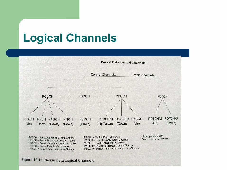
Logical Channels

Logical Channels
Mapped by the MAC to physical channels
Control channels for control, synchronization and signaling
Common
Dedicated
Broadcast
Packet Traffic channels – Encoded speech
– Encoded data

Control Channels
Packet Common Control Channel (PCCCH)
– Paging (PPCH)
– Random Access (PRACH)
– Grant (PAGCH)
– Packet Notification (PNCH)
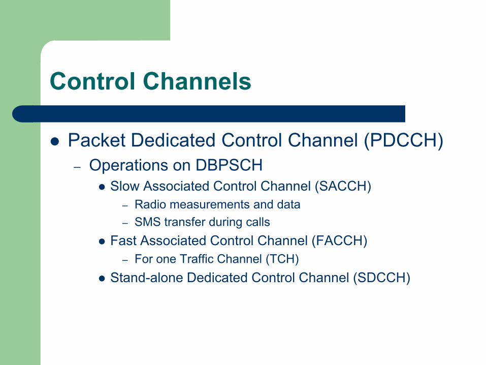
Control Channels
Packet Dedicated Control Channel (PDCCH)
– Operations on DBPSCH
Slow Associated Control Channel (SACCH)
– Radio measurements and data
– SMS transfer during calls
Fast Associated Control Channel (FACCH)
– For one Traffic Channel (TCH)
Stand-alone Dedicated Control Channel (SDCCH)

Control Channels
Packet Broadcast Control Channel (PBCCH)
– Frequency correction channels
– Synchronization channel (MS freq. vs. BS)
– Broadcast control channel for general information
on the base station
– Packet broadcast channels
Broadcast parameters that MS needs to access network
for packet transmission
Packet Traffic Channels
Traffic Channels (TCH)
Encoding of speech or user data
Channels are either predetermined multiplexed or multiplexing determined by MAC
Full rate/half rate
On both SBPSCH and DBPSCH
Modulation techniques – GMSK
– 8-PSK

Media Access Control (MAC)
Connection oriented
Connections are called Temporary Block Flows
(TBF)
– Logical unidirectional connection between two MAC entities
– Allocated resources on PDCH(s)
– One PDCH can accomodate multiple TBFs
– Temporary Flow Identity (TFI) is unique among concurrent
TBFs in the same direction
– Global_TFI to each station

MAC: TBF Establishment
MS initiated – One Phase Access, or
– Two Phase Access
MS BSS MS BSS
PACKET CHANNEL REQUEST PRACH
PACKET UPLINK ASSIGNMENT PAGCH
TBF Est. By MS: One Phase Access
PACKET CHANNEL REQUEST PRACH
PACKET RESOURCE REQUEST PACCH
PACKET UPLINK ASSIGNMENT PACCH
TBF Est. By MS: Two Phase Access
PACKET UPLINK ASSIGNMENT PAGCH

MAC: TBF Establishment
Network initiated
MS BSS
PACKET PAGING REQUEST PPCH
PACKET CHANNEL REQUEST PRACH
PACKET PAGING RESPONSE PACCH
PACKET DOWNLINK ASSIGNMENT PACCH or PAGCH
TBF Est. By Network
PACKET IMMEDIATE ASSIGNMENT PAGCH

MAC: Channel Access & Resource Allocation
Slotted Aloha – Used in PRACH
MSs send packets in uplink direction at the beginning of a slot
Collision: Back off -> timer (arbitrary) -> re-transmit
Time Division Multiple Access (TDMA) – Predefined slots allocated by BSS
– Contention-free channel access
– All logical channels except PRACH
MAC: Resource Allocation Mechanisms
Uplink State Flag (USF, 3bits) associated with an assigned PDCH (USF on each downlink Radio Block)
USF_GRANULARITY assigned during TBF est.
Dynamic Allocation 1. MS finds it’s USF in RLC/MAC PDU header. On the next uplink
block:
2. If USF_GRANULARITY=0, transmit one radio block
3. If USF_GRANULARITY=1, transmit four cons. radio blocks
Extended Dynamic Allocation – Same as Dynamic, except the four radio blocks are transmitted
on different PDCHs
Exclusive Allocation

Radio Link Control
Can provide reliability for MAC transmissions
Transparent mode – No functionality
Acknowledged mode – Selective Repeat ARQ
– Sender: Window
– Receiver: Uplink ACK/NACK or Downlink ACK/NACK
Unacknowledged mode – Controlled by numbering within TBF
– No retransmissions
– Replaces missing packets with dummy information bits

Radio Resource Control/Radio Resource
Radio resource management
RRC in Iu mode – Broadcasts system information
– Considers QoS requirements and ensures allocation of resources
RR in A/Gb mode – Maintains at least one PDCH for user data and control
signaling
Allocates new DBPSCHs
Intracell handover of DBPSCHs

QoS Support
End-to-end QoS may be specified by Service Level Agreements
Assumes that IP multimedia applications are able to – Define their requirements
– Negotiate their capabilities
– Identify and select available media components
GPRS specifies signaling that enable support for various traffic streams
– Constant/variable bit rate
– Connection oriented/connection less
– Etc.

QoS Profile for GPRS Bearers
Describes applications characteristics and QoS requirements
4 parameters: – Service precedence
3 classes
– Reliability parameter
3 classes
– Delay parameters
4 classes
– Throughput parameter
Maximum and mean bit rates
QoS Profile for GPRS Bearers
QoS profile is included in Packet Data
Protocol (PDP) context
Negotiation managed through PDP
procedures (activation, modification and
deactivation)

Packet Classification and Scheduling
TBF tagged with TFI
TFI different for each TBF
Packet scheduling algorithms are not defined by the
standard; defined and implemented by GPRS
network designers and carriers
GPRS *can* enable per-flow quantitative QoS
services with proper packet classification and
scheduling algorithms...Hmmm.

Mobility Management
Two procedures:
– GPRS Attach/Detach (towards SGSN/HLR)
Makes MS available for SMS over GPRS
Paging via SGSN
Notification of incoming packet
– PDP Context Activation/Deactivation
Associate with a GGSN
Obtain PDP address (e.g. IP)

GPRS Mobile “Station” States
GPRS protocol stack (MS) can take on 3 different states
– IDLE
– STANDBY
– ACTIVE/READY
Data can only be transmitted in the ACTIVE
state

Routing to MS
IDLE state
– No logical PDP context activated
– No network address (IP) registered for the terminal
– No routing of external data possible
– Only multicast messages to all GPRS handsets
available
Routing to MS
STANDBY state
– Only routing area is known
RA is defined by operator => allows individual
optimizations
– When downlink data is available, packet paging
message is sent to routing area
– Upon reception, MS sends it's cell location to the
SGSN and enters the ACTIVE state

Routing to MS
ACTIVE state
– SGSN knows the cell of the MS
– PDP contexts can be activated/deactivated
– Can remain in this state even if not data is transmitted (controlled by timer)
PDP Contexts
Packet Data Protocol (PDP)
– Session
– Logical tunnel between MS and GGSN
– Anchored GGSN for session
PDP activities
– Activation
– Modification
– Deactivation

PDP Context Procedures
MS initiated
MS BSS SGSN GGSN
Activate PDP Context Request
Create PDP Context
Request
Create PDP Context
Response
Activate PDP Context Accept

PDP Context Procedures
GGSN initiated
MS BSS SGSN GGSN
Activate PDP Context Request Create PDP Context
Request
Create PDP Context
Response Activate PDP Context Accept
Packets from ext. nw.
PDU notification req.
PDU notification resp.
Request PDP Context activation

Secondary PDP Contexts
Used when the QoS requirements differ from
Primary PDP Context
– Same IP address
– Same APN
E.g., for IMS; signaling on primary PDP
context and user data on secondary PDP
context

The End...