General Model RAMC Specifications Metal Short-stroke Rotameter · Metal Short-stroke Rotameter A...
20
GS 01R01B02-00E-E Copyright 2004 14th edition, April 2006 Model RAMC Metal Short-stroke Rotameter A float is guided concentrically to a special shaped conic metal tube.The position of this float is magnetically transmitted to the indicator.The short-tube Rotameter is used for measurement of flow rates of liquids and gases.Its special application is in troubled, opaque or aggressive mediums. The instrument is mounted in a vertical pipeline with flow direction upwards. The indicators are exchangeable without influence on the accuracy. FEATURES - Different process connections like flanges according EN and ASME - All wetted parts in stainless steel or PTFE - Different linings for aggressive fluids - Maximum flow 0.025 - 130 m³/h water resp. 0.75 - 1400 m³/h air (20 °C / 1.013 bar abs) - Accuracy class 1.6 resp. 2.5 with lining acc. VDI/VDE 3513 - Float damping to avoid float bouncing with gas applications - Optional heat tracing (with steam or fluid heat carrier) - Indicator in stainless steel, aluminium or plastic, protection class IP65 or IP66/67 - Local indicator without additional power supply - Microprocessor controlled transmitter with 24 V, 115 V or 230 V power supply - Intrisically safe version (Ex-i) and flame proof version (Ex-d) - Dust explosion proof - Suitable for SIL application, SIL report on request - Limit switches Electronic transmitter as standard with local-controlling display with the following features : - Flow indication (totalize, actual, percent) - Indication of different volume- and massflow units - Second (manual) calibration storing - Patented float blocking indication function - Signal output damping - Error message indication - Temperature measurement in the electronic transmitter - HART- communication General Specifications Features .................................................................................... page 1 Standard Specification .............................................................. page 2 Hazardous Area Specifications ................................................. page 4 Installation ................................................................................. page 7 Model Specifications ................................................................. page 10 Options ...................................................................................... page 11 Process connection table for metal tubes ................................. page 12 Flow tables for metal tubes ....................................................... page 13 Process connection and flow table for tubes with PTFE lining.. page 14 Temperature graphs .................................................................. page 15 Dimensions and weights ........................................................... page 16 CONTENTS
Transcript of General Model RAMC Specifications Metal Short-stroke Rotameter · Metal Short-stroke Rotameter A...
GS 01R01B02-00E-E Copyright 2004
14th edition, April 2006
Model RAMCMetal Short-stroke Rotameter
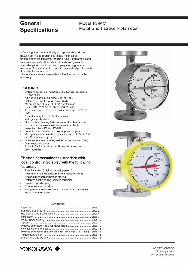
A float is guided concentrically to a special shaped conicmetal tube.The position of this float is magneticallytransmitted to the indicator.The short-tube Rotameter is usedfor measurement of flow rates of liquids and gases.Itsspecial application is in troubled, opaque or aggressivemediums. The instrument is mounted in a vertical pipeline withflow direction upwards.The indicators are exchangeable without influence on theaccuracy.
FEATURES- Different process connections like flanges according
EN and ASME- All wetted parts in stainless steel or PTFE- Different linings for aggressive fluids- Maximum flow 0.025 - 130 m³/h water resp.
0.75 - 1400 m³/h air (20 °C / 1.013 bar abs)- Accuracy class 1.6 resp. 2.5 with lining acc. VDI/VDE
3513- Float damping to avoid float bouncing
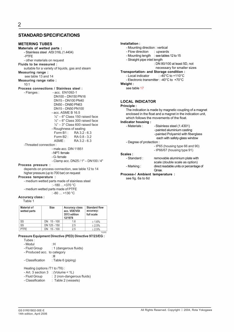
with gas applications- Optional heat tracing (with steam or fluid heat carrier)- Indicator in stainless steel, aluminium or plastic,
protection class IP65 or IP66/67- Local indicator without additional power supply- Microprocessor controlled transmitter with 24 V, 115 V
or 230 V power supply- Intrisically safe version (Ex-i) and flame proof version (Ex-d)- Dust explosion proof- Suitable for SIL application, SIL report on request- Limit switches
Electronic transmitter as standard withlocal-controlling display with the followingfeatures :- Flow indication (totalize, actual, percent)- Indication of different volume- and massflow units- Second (manual) calibration storing- Patented float blocking indication function- Signal output damping- Error message indication- Temperature measurement in the electronic transmitter- HART- communication
GeneralSpecifications
Features .................................................................................... page 1
Standard Specification .............................................................. page 2
Hazardous Area Specifications ................................................. page 4
Installation ................................................................................. page 7
Model Specifications ................................................................. page 10
Options ...................................................................................... page 11
Process connection table for metal tubes ................................. page 12
Flow tables for metal tubes ....................................................... page 13
Process connection and flow table for tubes with PTFE lining.. page 14
Temperature graphs .................................................................. page 15
Dimensions and weights ........................................................... page 16
CONTENTS
GS 01R01B02-00E-E14th edition, April 2006
2
All Rights Reserved. Copyright 2004, Rota Yokogawa
STANDARD SPECIFICATIONS
METERING TUBESMaterials of wetted parts :
- Stainless steel AISI 316L (1.4404)- PTFE- other materials on request
Fluids to be measured :suitable for a variety of liquids, gas and steam
Measuring range : see table 13 and 14
Measuring range ratio :10:1
Process connections / Stainless steel :- Flanges : - acc. EN1092-1
DN100 – DN150 PN16 DN15 – DN100 PN40 DN50 – DN80 PN63 DN15 – DN50 PN100- acc. ASME B 16.5 ½” – 6" Class 150 raised face ½” – 6" Class 300 raised face ½” – 3" Class 600 raised face- Roughness of sealing Form B1 : RA 3.2 - 6.3 Form B2 : RA 0.8 - 3.2 ASME : RA 3.2 - 6.3
-Threated connection :- male acc. DIN 11851- NPT- female- G- female- Clamp acc. DN25 / 1" – DN100 / 4"
Process pressure :depends on process connection, see table 12 to 14higher pressure (up to 700 bar) on request
Process temperature :- medium wetted parts made of stainless steel
: -180 …+370 °C- medium wetted parts made of PTFE
: -80 … +130 °CAccuracy class : Table 1
Pressure Equipment Directive (PED) Directive 97/23/EG :Tubes :- Modul : H- Fluid Group : 1 (dangerous fluids)- Produced acc. to category
: III- Classification : Table 6 (piping)
Heating (options /T1 to /T6) :- Art. 3 section 3 : (Volume < 1L)- Fluid Group : 2 (non-dangerous fluids)- Classification : Table 2 (vessels)
Installation :- Mounting direction : vertical- Flow direction : upwards- Mounting length : see tables 12 to 15- Straight pipe inlet length
: DN 80/100 at least 5D, not necessary for smaller sizes
Transportation- and Storage condition :- Local indicator : -40°C to +110°C- Electronic transmitter : -40°C to +70°C
Weight :see table 17
LOCAL INDICATORPrinciple :
The indication is made by magnetic coupling of a magnetenclosed in the float and a magnet in the indication unit,which follows the movements of the float.
Indicator housing :- Materials : -Stainless steel (1.4301)
-painted aluminium casting-painted Polyamid with fiberglass
each with safety-glass window- Degree of protection :
- IP65 (housing type 66 and 90)- IP66/67 (housing type 91)
Scales :- Standard : removable aluminium plate with
scale (double scale as option)- Marking : direct readable units or percentage of
Qmax.Process-/ Ambient temperature :
see fig. 6a to 6d
Material of
wetted parts
Size Accuracy class
acc. VDE/VDI
3513 edition
12/1978
Standard flow accuracy:
full scale
SS DN 15 - 100 1.6 ± 1.6%
SS DN 125 - 150 2.5 ± 2.5%
PTFE DN 15 - 100 2.5 ± 2.5% T0.EPS

GS 01R01B02-00E-E14th edition, April 2006
3
All Rights Reserved. Copyright 2004, Rota Yokogawa
ELECTRONIC TRANSMITTER(Indicator/Transmitter Code –E and -H)Digital display :
8-digits 7-segment-LC-display character height 6 mmPower supply :
- 4-wire units with galvanic isolation :- 230 V AC +10 %/-15 %, 50/60 Hz, fuse 0.063 A, time lag, (5x20) mm- 115 V AC +10%/-15 %, 50/60 Hz, fuse 0.125 A, time lag, (5x20) mm
- 2/3-wire units : - U = 13.5 V... 30 V DCOutput signal :
- 4-wire units : - 0 - 20 mA, 4 – 20 mA- pulse output (option /CP) max. frequency 4 Hz see fig. 3
- 3-wire units : 0 - 20 mA, 4 - 20 mA- 2-wire units : 4 - 20 mAThe 20mA point is selectable between 60% and 100% of Qnom.
HART-communication :- 2-wire units : 4 – 20 mA
Load resistance :- 4-wire units : ≤ 500 Ω- 2/3-wire unit : ≤ (U-13.5 V)/20 mA- HART-version : 250 … 500 Ω
Process-/ Ambient temperature :The dependency of the process temperature from theambient temperature is shown in fig. 6a to fig. 6d.The internal temperature of the electronic transmitter canbe indicated on the display or checked via HART communication.
Measurement of the internal transmitter temperature :- Range : -25 °C to +70 °C- Accuracy : ±5 °C
Storage temperature :-40 °C to +70 °C
Linearity : :± 0.2 % f.s.
Hysteresis 1) :± 0.1 % f.s.
Repeatabillity 1) :± 0.1 % f.s.
Influence of power supply 1) :± 0.1 % f.s.
Temperature coefficient of the output signal 1) :± 0.5 %/10 K f.s.
AC-part of output signal 1) :± 0.15 % f.s.
Long-time stability 1) :± 0.2 % /year
Max. output signal :21.5 mA
Output signal in case of failure :≤ 3.6 mA (acc. NE 43)
Response time (99%) :About 1.5 s (damping 1s)
Electromagnetic compatibility (EMC) :- Emission acc. EN 55011: 2003 : class A, group 1- EN 61000-3-2 : 2001- EN 61000-3-3 : 2002- Immunity acc. EN 61326 : 2002 : Criterion A, restriction :HF-immunity between 500 MHz and 750 MHz : criterion B
Unit safety acc. DIN EN61010-1 : 2002- Overvoltage category : II (acc, VDE 0110 or IEC 664)- Pollution degree : I- Safety class : I (with 115 / 230V AC power supply)
III (with 24V DC power supply)
POWER SUPPLY FOR ELECTRONIC TRANSMITTER(Option /U__)Type :
power supply with galvanically separated input and output- SINEAX B811, HART- compatible type available
Supply voltage :- 24 V to 60 V AC/DC- 85 V to 230 V AC
Maximum load :750 Ω
Output signal :0/4 mA - 20 mA
CABLE GLAND (for transmitter –E and –H) :Size :
- M16x1.5 (standard)- M20x1.5 (option /A13; standard for option /KF1)- ½” NPT (option /A5)
Cable diameter :6 – 9 mm
Maximum cross section of core :Ø 1.5 mm²
LIMIT SWITCHES IN STANDARD VERSION(option /K1 to /K3)Type :
Inductive proximity switch S 3.5-NO acc. DIN EN 60947-5-6Nominal voltage :
8 V DCOutput signal :
≤ 1 mA or ≥ 3 mA
LIMIT SWITCHES IN FAIL SAFE VERSION(option /K6 to /K10)Type :
Inductive proximity switch SJ3.5-SN; SJ3.5-S1Nacc. DIN EN 60947-5-6 (NAMUR)
Nominal voltage :8 V DC
Output signal :≤ 1 mA or ≥ 3 mA
HYSTERESIS OF LIMIT SWITCHESMin-contact :
- pointer movement : ≈ 0.5 mm- float movement : ≈ 0.8 mm
Max-contact :- pointer movement : ≈ 0.5 mm- float movement : ≈ 0.6 mm
CABLE GLAND (option /K1 to /K10)Size :
- M16x1.5 (standard)- M20x1.5 (option /A13; standard for option /KF1)- ½” NPT (option /A5)
Cable diameter :6 – 9 mm
Maximum cross section of core :Ø 1.5 mm²
1) referenced to 20°C ambient temperature
GS 01R01B02-00E-E14th edition, April 2006
4
All Rights Reserved. Copyright 2004, Rota Yokogawa
HAZARDOUS AREA SPECIFICATIONSINTRINSIC SAFETYAttention :The maximum ambient temperature of the transmitter or of thelimit switches according to the temperature class may not beexceeded because of heat transmission from the medium.Table 5 Entity parameters of electronic transmitter
Intrinsically safe electronic transmitter with ATEX-certification (option /KS1) :Certificate :
PTB 96 ATEX 2160XOutput signal :
4–20 mA (2-wire unit, 3-wire unit) ; 0-20mA (3-wire unit)Explosion proof :
EEx ia IIC T6; group II ; category 2GEntity parameter :
see table 5
Electronic transmitter for category 3 (option /KN1) :Output signal :
4–20 mA (2-wire unit, 3-wire unit) ; 0-20mA (3-wire unit)Explosion proof :
EEx nL IIC T6 protection „nL”; group II ; category 3GDust proof :
EEx II 3D; group II ; category 3DMax. surface temperature : 80°C
Entity parameter :see table 5
Intrinsically safe RAMC with SAA -certification(Australia) (option /SS1) :Certificate :
AUS Ex3777XOutput signal :
4–20 mA (2-wire unit)Explosion proof :
Ex ia IIC T5Max. Tamb. :
65°C (with limit switches 40°C)Degree of protection :
IP54Entity parameter of electronic transmitter :
see table 5Limit switches :
option /K6 to /K10Entity parameter of limit switches :
see certificate AUS Ex 02.3839X
POWER SUPPLY FOR LIMIT SWITCHES(Option /W__)Type :
Transmitter relay acc. DIN EN 50227 (NAMUR)- KFA6-SR2-Ex1-W (230 V AC)- KFA5-SR2-Ex1-W (115 V AC)- KFD2-SR2-Ex1-W (24 V DC)
Power supply :- 230 V AC ± 10%, 45-65Hz- 115 V AC ± 10%, 45-65Hz- 24 V DC ± 25%
Relay output :1 or 2 potential-free changeover contact(s)
Switching capacity :max. 250V AC, max. 2 A
SWITCHING LEVELS FOR LIMIT SWITCHESTable 2 Limit switch as Min, Max and Min-Max-contact
in standard and fail-safe version.
Table 3 Limit switch as Min-Min-contact in standard and fail-safe version.
Table 4 Limit switch as Max-Max-contact in standard and fail-safe version.
Function
MAX
MIN
Pointer
above LV
below LV
above LVbelow LV
T2.EPS
SC 3,5-N0 SJ 3,5-SN
Switch Signal Switch Signal Fail safe
on
off
on
off
offon
offon
1mA3mA 3mA
3mA 3mA1mA
1mA
1mA1mA
1mA
Note : LV = Limit value
Function
upper
MIN
lower
MIN
Pointer
above LV
below LVabove LV
below LV
T3.EPS
SJ 3,5-SN SJ 3,5-S1N
Switch Signal Switch Signal Fail safe
off
on
offon
1mA3mA1mA
3mA
1mA
1mA-----
-----
----------
----------
----------
Note : LV = Limit value
Function
upper
MAX
lower
MAX
Pointer
T4.EPS
SJ 3,5-SN SJ 3,5-S1N
Switch Signal Switch Signal Fail safe
on
off
onoff
1mA3mA
1mA 1mA
1mA
3mA
-------- ----
----
----
---- ----
----
above LVbelow LVabove LV
below LV
Note : LV = Limit value
T1.EPS
30
30
30
Ui [V] Ii [mA] Pi [W] Ci [nF] Li [mH] Ta max [°C]
KS1
KN1
SS1
101 1.4 0.15 704.16
152 1.4 0.15 704.16
186 1.4 0.73 653.6 *)
*) with limit switches : 40°C
30NS1 101 1.4 0.15 704.16
Note :If 2 Fail-Safe limit switches option /K6 ... /K10 are used in aRAMC also 2 power supplies option /W2E or /W4E arenecessary.
GS 01R01B02-00E-E14th edition, April 2006
5
All Rights Reserved. Copyright 2004, Rota Yokogawa
Intrinsically safe RAMC with NEPSI -certification(China) (option /NS1) :Certificate :
GYJ05152Output signal :
4–20 mA (2-wire unit, 3-wire unit) ; 0-20mA (3-wire unit)Explosion proof :
Ex ia IIC T6Max. Tamb. :
70°CEntity parameter of electronic transmitter :
see table 5Limit switches :
option /K1 to /K10Entity parameter of limit switches :
see certificate NEPSI GYJ03201X
Power Supply for the intrinsically safe electronictransmitter (option /U__)Type :
Intrinsically safe power supply with galvanicallyseparated input and output- SINEAX B811, HART- compatible type available
Certificate :PTB 97 ATEX 2083
Supply voltage :- 24 V to 60 V AC/DC
- 85 V to 230 V ACMaximum load impedance :
750 ΩOutput signal :
0/4 mA - 20 mAControl circuit :
Intrinsically safe [EEx ia] IIC group II, category (1)GEntity parameters :
see fig 4
Intrinsically safe and dust proof limit switches withATEX-certification (option /K1 .. /K10 with /KS1) :Certificate :
- PTB 99 ATEX 2219X ( SC3.5-NO)- PTB 00 ATEX 2049X (SJ 3.5-S.N)- ZELM 03 ATEX 0128X (for dust proof)
Explosion proof :EEx ia IIC T6, group II category 2G
Dust proof (only indicator “T”) :EEx iaD 20 T 108 °C, group I I category 1DMax. surface temperature : T108°C
Entity parameter : see certificate of conformity
Limit switches for category 3 (option /K1 .. /K10 with /KN1) :Explosion proof :
EEx nL IIC T6 X protection „nL”; group II ; category 3GDust proof :
EEx II 3D; group II ; category 3DMax. surface temperature : T112°C
Entity parameter :see specification of SC3,5-N0 Blue (P&F)* (/K1 ... /K3)see specification of SJ3,5-SN (P&F)* (/K6 ... /K10)see specification of SJ3,5-S1N (P&F)* (/K6 ... /K10) * P&F = Pepperl & Fuchs
Temp. class Max. ambient temperature [°C]
Max. process temperature [°C]
T6 60 85
T5 60 100
T4 60 135
T3 60 200
T2 60 300
T1 60 370 T3Ex.EPS
Power supply for intrinsically safe limit switches(option W__) :Type :
- KFA6-SR2-Ex1-W (230 V AC)- KFA5-SR2-Ex1-W (115 V AC)- KFD2-SR2-Ex1-W (24 V DC)
Certificate :- PTB 00 ATEX 2081 (115/230 V AC)- PTB 00 ATEX 2080 (24 V DC)
Control circuit :[EEx ia] IIC; group II ; category (1)GD
Entity parameter :see fig. 4
FLAME PROOF AND DUST PROOF RAMC
Flame proof and dust proof RAMC with ATEX-certificate(option /KF1) :Certificate :
IBExU 05 ATEX 1086Flame proof :
EEx d IIC T1 ... T6 ; group II ; category 2GDust proof :
Group II ; category 1DMax. surface temperature TX :corresponding process
temperatureHousing :
Painted aluminium casting, type 91Output signal :
4–20 mA (2-wire unit, 3-wire unit) ; 0-20mA (3-wire unit)Power supply :
2- or 3- wire unitAmbient temperature :
-20 °C to 60 °C (category 2G / 2D)-20 °C to 55 °C (category 1D)
Minimum process temperature :-20°C
Threads for cable glands :- M20x1.5 (standard)- ½” NPT (option /A5)
Temperature classification :
Table 6 For RAMC with limit switch
Table 7 For RAMC with electronic transmitter
Table 8 For RAMC with limit switch with extension(option /A16) :
Temp. class Max. ambient temperature [°C]
Max. processtemperature [°C]
T6 60 85
T5 60 100
T4 … T1 60 120 T1Ex.EPS
Temp. class Max. ambient temperature [°C]
Max. process temperature [°C]
T6 60 70
T5 … T1 60 40
70 100
T2Ex.EPS
GS 01R01B02-00E-E14th edition, April 2006
6
All Rights Reserved. Copyright 2004, Rota Yokogawa
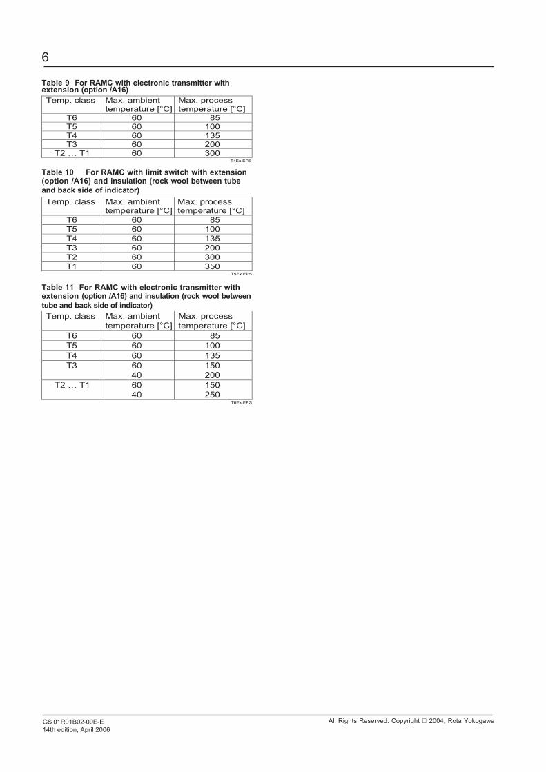
Table 9 For RAMC with electronic transmitter withextension (option /A16)
Table 10 For RAMC with limit switch with extension(option /A16) and insulation (rock wool between tubeand back side of indicator)
Table 11 For RAMC with electronic transmitter withextension (option /A16) and insulation (rock wool betweentube and back side of indicator)Temp. class Max. ambient
temperature [°C] Max. process temperature [°C]
T6 60 85
T5 60 100
T4 60 135
T3 60 40
150 200
T2 … T1 60 40
150 250
T6Ex.EPS
Temp. class Max. ambient temperature [°C]
Max. process temperature [°C]
T6 60 85
T5 60 100
T4 60 135
T3 60 200
T2 60 300
T1 60 350 T5Ex.EPS
Temp. class Max. ambient temperature [°C]
Max. process temperature [°C]
T6 60 85
T5 60 100
T4 60 135
T3 60 200
T2 … T1 60 300 T4Ex.EPS
GS 01R01B02-00E-E14th edition, April 2006
7
All Rights Reserved. Copyright 2004, Rota Yokogawa
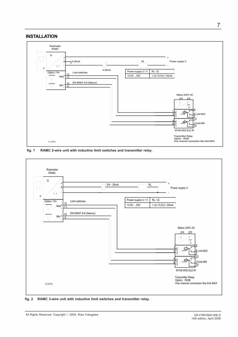
fig. 1 RAMC 2-wire unit with inductive limit switches and transmitter relay.
fig. 2 RAMC 3-wire unit with inductive limit switches and transmitter relay.
1515
4
6
3
1
1414
1212
10101111
87
9U
F
G
RAMCRAMC
A Power supply UPower supply U
Mains 230V ACMains 230V AC
KFA6-SR2-Ex2.WKFA6-SR2-Ex2.W
Option: /W2BOption: /W2BTransmitter RelayTransmitter Relay
Limit MINLimit MIN
Limit MAXLimit MAX
Option / KnOption / Kn
RotameterRotameter
MaxMax
MinMin
1212
1111
1010
9
Limit switchesLimit switches
EN 60947-5-6 (Namur)EN 60947-5-6 (Namur)
One channel connection like limit MAXOne channel connection like limit MAX
0/4 - 20mA0/4 - 20mA RLRL
-
+
-
+
-
+
-
+
~ ~
+-
+-
Power supply U / VPower supply U / V RL / RL / Ω13.5V ...30V13.5V ...30V < (U-13.5V) / 20mA< (U-13.5V) / 20mA
F2.EPS
1515
4
6
3
1
1414
1212
10101111
87
9U
F
G
RAMCRAMC
A Power supply UPower supply U
Mains 230V ACMains 230V AC
KFA6-SR2-Ex2.WKFA6-SR2-Ex2.W
Option: /W2BOption: /W2BTransmitter RelayTransmitter Relay
Limit MINLimit MIN
Limit MAXLimit MAX
Option / KnOption / Kn
RotameterRotameter
4-20mA4-20mA
MaxMax
MinMin
1212
1111
1010
9
Limit switchesLimit switches
EN 60947-5-6 (Namur)EN 60947-5-6 (Namur)
One channel connection like limit MAXOne channel connection like limit MAX
4-20mA4-20mA
RLRL
-
+
-
+
-
+
-
+
~ ~
+-
+-
Power supply U / VPower supply U / V RL / RL / Ω13.5V ...30V13.5V ...30V < (U-13.5V) / 20mA< (U-13.5V) / 20mA
F1.EPS
INSTALLATION
GS 01R01B02-00E-E14th edition, April 2006
8
All Rights Reserved. Copyright 2004, Rota Yokogawa
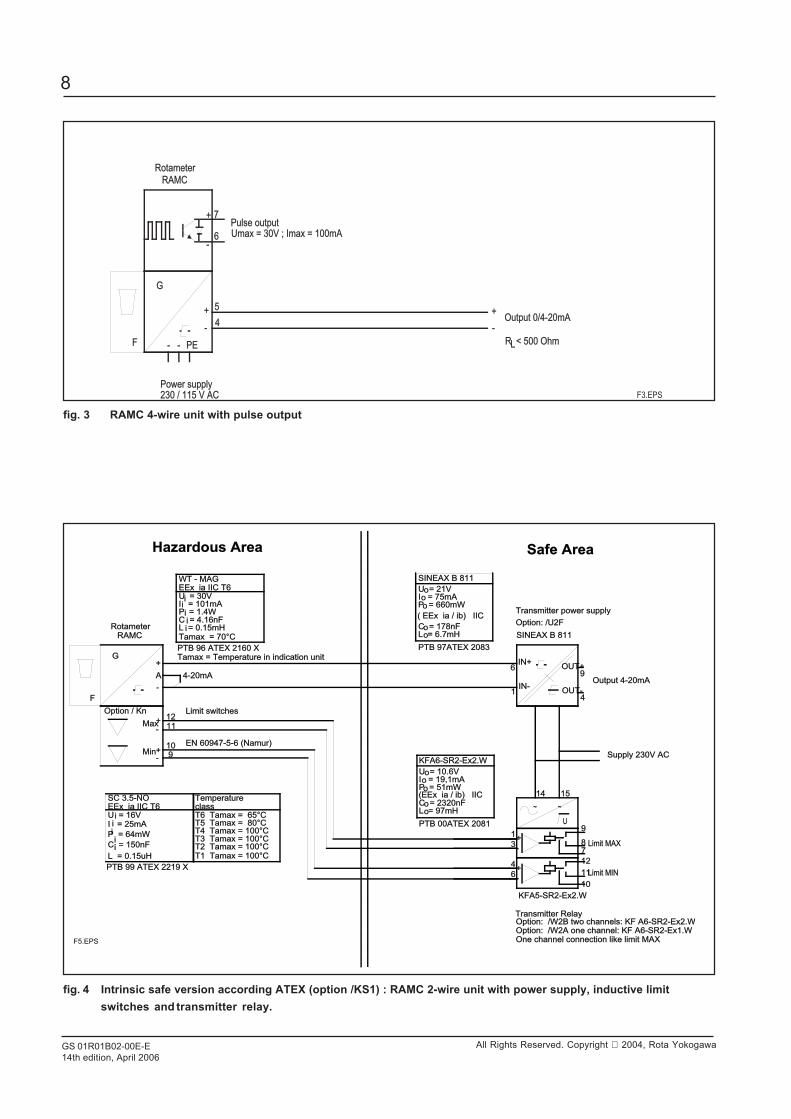
fig. 3 RAMC 4-wire unit with pulse output
fig. 4 Intrinsic safe version according ATEX (option /KS1) : RAMC 2-wire unit with power supply, inductive limitswitches and transmitter relay.
4
9
1515
4
6
3
1
1414
1212
1010
1111
87
9
12121111
10109
6
1
U
F
G
RAMCRAMC
AOutput 4-20mAOutput 4-20mA
Supply 230V ACSupply 230V AC
KFA5-SR2-Ex2.WKFA5-SR2-Ex2.W
Option: /W2B two channels: KF A6-SR2-Ex2.WOption: /W2B two channels: KF A6-SR2-Ex2.WTransmitter RelayTransmitter Relay
Limit MINLimit MIN
Limit MAXLimit MAX
Option / KnOption / Kn
RotameterRotameter
4-20mA4-20mA
MaxMax
MinMin
Limit switchesLimit switches
EN 60947-5-6 (Namur)EN 60947-5-6 (Namur)
One channel connection like limit MAXOne channel connection like limit MAX
I = 101mAI = 101mAP = 1.4WP = 1.4WC = 4.16nFC = 4.16nF
U = 30VU = 30V
L = 0.15mHL = 0.15mH
WT - MAGWT - MAGEEx ia IIC T6EEx ia IIC T6
Tamax = 70Tamax = 70°C
PTB 96 ATEX 2160 XPTB 96 ATEX 2160 XTamax = Temperature in indication unitTamax = Temperature in indication unit
C = 150nFC = 150nF
EEx ia IIC T6EEx ia IIC T6
L = 0.15uHL = 0.15uH
SC 3.5-NOSC 3.5-NO
P = 64mWP = 64mW
I = 25mAI = 25mAU = 16VU = 16V
TemperatureTemperature
T4 Tamax = 100T4 Tamax = 100°CT3 Tamax = 100T3 Tamax = 100°CT2 Tamax = 100T2 Tamax = 100°CT1 Tamax = 100T1 Tamax = 100°C
classclass
T5 Tamax = 80T5 Tamax = 80°CT6 Tamax = 65T6 Tamax = 65°C
PTB 99 ATEX 2219 XPTB 99 ATEX 2219 X
C = 178nFC = 178nF
I = 75mAI = 75mAP = 660mWP = 660mW
U = 21VU = 21V
L = 6.7mHL = 6.7mH
PTB 97ATEX 2083PTB 97ATEX 2083
( EEx ia / ib) IIC( EEx ia / ib) IIC
SINEAX B 811SINEAX B 811
Transmitter power supplyTransmitter power supply
Option: /U2FOption: /U2F
SINEAX B 811SINEAX B 811
Option: /W2A one channel: KF A6-SR2-Ex1.WOption: /W2A one channel: KF A6-SR2-Ex1.W
C = 2320nFC = 2320nF
I = 19,1mAI = 19,1mAP = 51mWP = 51mW
U = 10.6VU = 10.6V
L = 97mHL = 97mH
PTB 00ATEX 2081PTB 00ATEX 2081
(EEx ia / ib) IIC(EEx ia / ib) IIC
KFA6-SR2-Ex2.WKFA6-SR2-Ex2.W
-
+
-
+
-
+
~ ~
+-
+-
i
ii
i
iii
ii
o
o
o
oo
OUT-OUT-
OUT+OUT+IN+IN+
IN-IN-
o
o
o
oo
i
Hazardous AreaHazardous Area Safe AreaSafe Area
F5.EPS
F
G
RAMCRAMC
230 / 115 V AC230 / 115 V AC
4
Power supplyPower supply
Output 0/4-20mAOutput 0/4-20mA
R < 500 OhmR < 500 OhmL
RotameterRotameter
PEPE--
5
7
6
Pulse outputPulse outputUmax = 30V ; Imax = 100mAUmax = 30V ; Imax = 100mA
-
+
-
+
+
-
F3.EPS
GS 01R01B02-00E-E14th edition, April 2006
9
All Rights Reserved. Copyright 2004, Rota Yokogawa
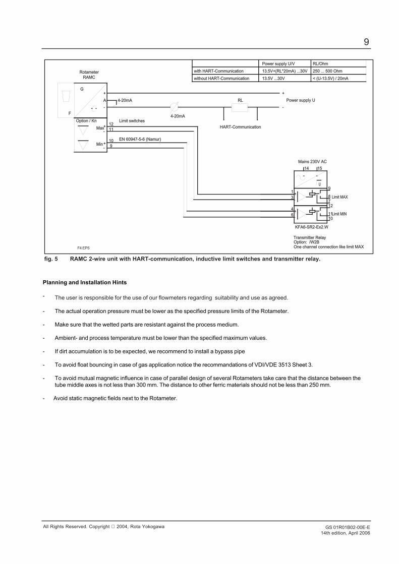
fig. 5 RAMC 2-wire unit with HART-communication, inductive limit switches and transmitter relay.
Planning and Installation Hints
- The user is responsible for the use of our flowmeters regarding suitability and use as agreed.
- The actual operation pressure must be lower as the specified pressure limits of the Rotameter.
- Make sure that the wetted parts are resistant against the process medium.
- Ambient- and process temperature must be lower than the specified maximum values.
- If dirt accumulation is to be expected, we recommend to install a bypass pipe
- To avoid float bouncing in case of gas application notice the recommandations of VDI/VDE 3513 Sheet 3.
- To avoid mutual magnetic influence in case of parallel design of several Rotameters take care that the distance between thetube middle axes is not less than 300 mm. The distance to other ferric materials should not be less than 250 mm.
- Avoid static magnetic fields next to the Rotameter.
1515
4
6
3
1
1414
1212
10101111
87
9U
F
G
RAMCRAMC
A Power supply UPower supply U
Mains 230V ACMains 230V AC
KFA6-SR2-Ex2.WKFA6-SR2-Ex2.W
Option: /W2BOption: /W2BTransmitter RelayTransmitter Relay
Limit MINLimit MIN
Limit MAXLimit MAX
Option / KnOption / Kn
RotameterRotameter
4-20mA4-20mA
MaxMax
MinMin
1212
1111
1010
9
Limit switchesLimit switches
EN 60947-5-6 (Namur)EN 60947-5-6 (Namur)
One channel connection like limit MAXOne channel connection like limit MAX
4-20mA4-20mA
RLRL
HART-CommunicationHART-Communication
with HART-Communicationwith HART-Communication
without HART-Communicationwithout HART-Communication
Power supply U/VPower supply U/V RL/OhmRL/Ohm
13.5V+(RL*20mA) ...30V13.5V+(RL*20mA) ...30V
13.5V ...30V13.5V ...30V < (U-13.5V) / 20mA< (U-13.5V) / 20mA
250 ... 500 Ohm250 ... 500 Ohm
-
+
-
+
-
+
-
+
~ ~
+-
+-
F4.EPS
GS 01R01B02-00E-E14th edition, April 2006
10
All Rights Reserved. Copyright 2004, Rota Yokogawa
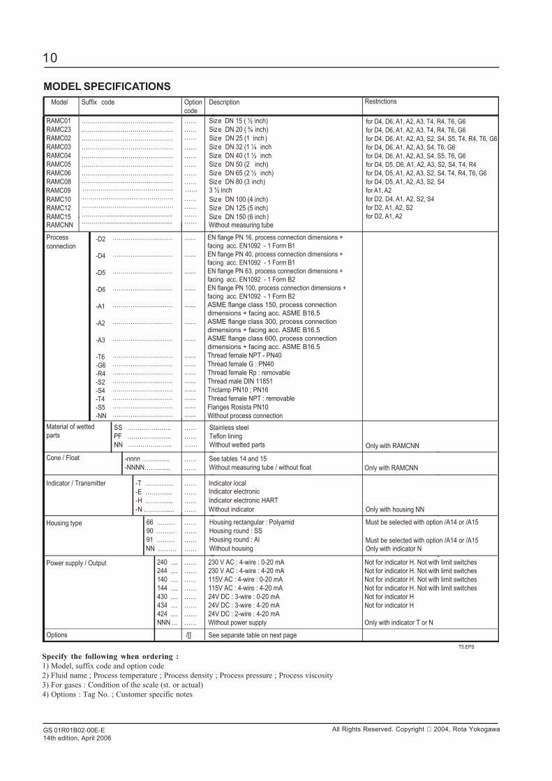
MODEL SPECIFICATIONSModel Suffix code Option
code
Description
RAMC01
RAMC23
RAMC02
RAMC03
RAMC04
RAMC05
RAMC06
RAMC08
RAMC10
RAMC12
RAMC15
………………………………………
………………………………………
………………………………………
………………………………………
………………………………………
………………………………………
………………………………………
………………………………………
………………………………………
………………………………………
………….......................................
……
……
……
……
……
……
……
……
………………
Size DN 15 ( ½ inch)
Size DN 20 ( ¾ inch)
Size DN 25 (1 inch)
Size DN 32 (1 ¼ inch
Size DN 40 (1 ½ inch
Size DN 50 (2 inch)
Size DN 65 (2 ½ inch)
Size DN 80 (3 inch)
Size DN 100 (4 inch)
Size DN 125 (5 inch)
Size DN 150 (6 inch)
Process
connection
………….………...……
………….………...……
………….………...……
………….………...……
………….………...……
………….………...……
………….………...……
………….………...……
………….………...……
………….………...……
………….………...……
………….………...……
………….………...……
………….………...……
………….………...……
.......
.......
.......
.......
.......
.......
.......
.......
.......
.......
.......
.......
.......
.......
.......
EN flange PN 16, process connection dimensions +
facing acc. EN1092 - 1 Form B1
EN flange PN 40, process connection dimensions +
facing acc. EN1092 - 1 Form B1
EN flange PN 63, process connection dimensions +
facing acc. EN1092 - 1 Form B2
EN flange PN 100, process connection dimensions +
facing acc. EN1092 - 1 Form B2
ASME flange class 150, process connection
dimensions + facing acc. ASME B16.5
ASME flange class 300, process connection
dimensions + facing acc. ASME B16.5
ASME flange class 600, process connection
dimensions + facing acc. ASME B16.5
Thread female NPT - PN40
Thread female G : PN40
Thread female Rp : removable
Thread male DIN 11851
Triclamp PN10 ; PN16
Thread female NPT : removable
Flanges Rosista PN10
Without process connection
Material of wetted
parts SS …….……….….. PF
NN
…………….…...
……
……
Stainless steel
Teflon lining
Without wetted parts
Cone / Float -nnnn …….........
-NNNN……........
……
See tables 14 and 15
Without measuring tube / without float
Indicator / Transmitter T ………......
E ……….....
H ..…….......
N ……….......
……
……
……
……
Indicator local
Without indicator
Housing type 66 ………
90 ………
91 ………
……
……
……
Housing rectangular : Polyamid Housing round : SS Housing round : Al
Power supply / Output 240 ....
244 ....
140 ....
144 ....
430 ....
434 ....
424 ....
NNN ...
-
-
-
-
……
……
……
……
……
……
……
……
230 V AC : 4-wire : 0-20 mA
230 V AC : 4-wire : 4-20 mA
115V AC : 4-wire : 0-20 mA
115V AC : 4-wire : 4-20 mA
24V DC : 3-wire : 0-20 mA
24V DC : 3-wire : 4-20 mA
24V DC : 2-wire : 4-20 mA
Without power supply
/[]
T5.EPS
RAMC09 3 ½ inch
Indicator electronic HART
……………………………………… ……
See separate table on next page
RAMCNN…………....................................... ……
Without measuring tube
…………….…... ……
……
NN ……… …… Without housing
Options
Indicator electronic
Restrictions
Only with housing NN
Only with indicator N
Must be selected with option /A14 or /A15
Must be selected with option /A14 or /A15
Not for indicator H. Not with limit switches
Not for indicator H. Not with limit switches
Not for indicator H. Not with limit switches
Not for indicator H. Not with limit switches
Not for indicator H
Not for indicator H
Only with indicator T or N
for D4, D6, A1, A2, A3, T4, R4, T6, G6
for D4, D6, A1, A2, A3, T4, R4, T6, G6
for D4, D6, A1, A2, A3, S2, S4, S5, T4, R4, T6, G6
for D4, D6, A1, A2, A3, S4, T6, G6
for D4, D6, A1, A2, A3, S4, S5, T6, G6
for D4, D5, D6, A1, A2, A3, S2, S4, T4, R4
for D4, D5, A1, A2, A3, S2, S4, T4, R4, T6, G6
for D4, D5, A1, A2, A3, S2, S4
for A1, A2
for D2, D4, A1, A2, S2, S4
for D2, A1, A2, S2
for D2, A1, A2
Only with RAMCNN
Only with RAMCNN
-D2
-D4
-D5
-D6
-A1
-A2
-A3
-T6
-G6
-R4
-S2
-S4
-T4
-S5
-NN
Specify the following when ordering :1) Model, suffix code and option code2) Fluid name ; Process temperature ; Process density ; Process pressure ; Process viscosity3) For gases : Condition of the scale (st. or actual)4) Options : Tag No. ; Customer specific notes
GS 01R01B02-00E-E14th edition, April 2006
11
All Rights Reserved. Copyright 2004, Rota Yokogawa
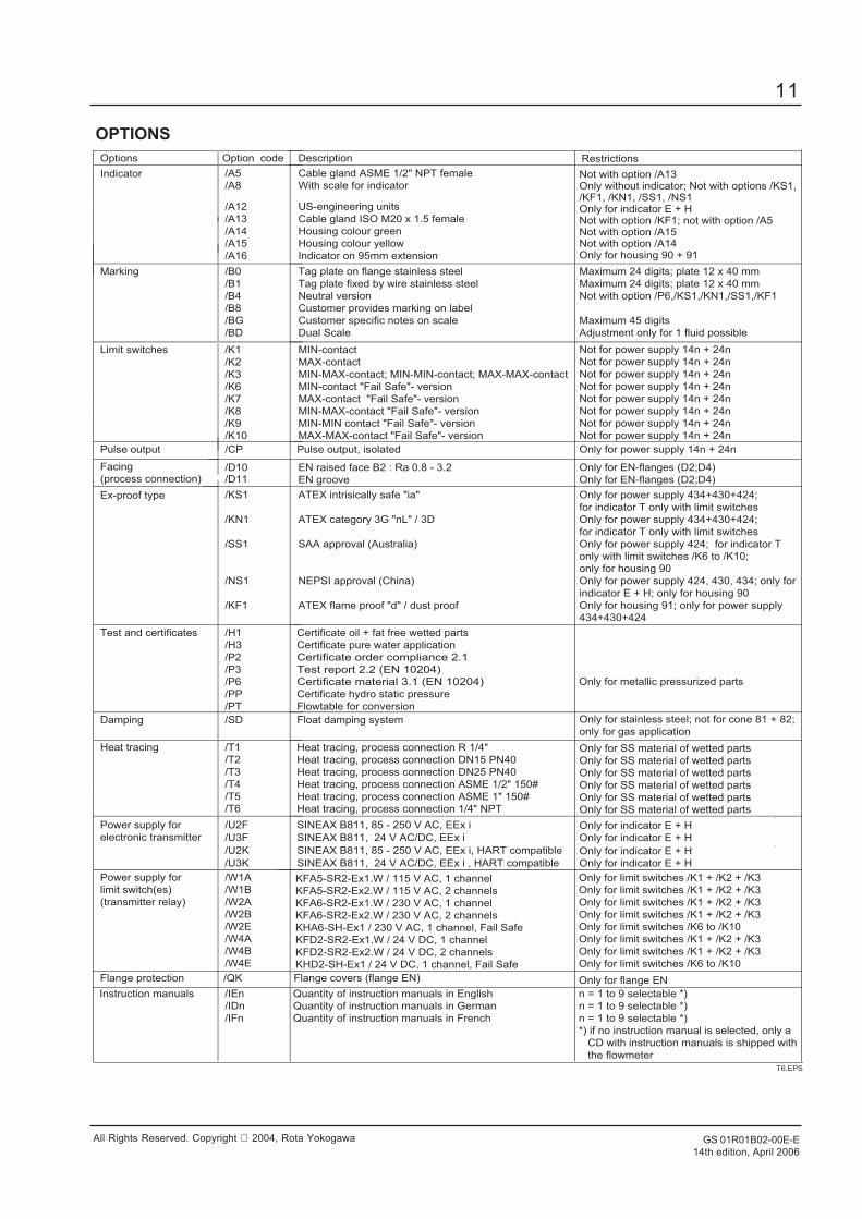
OPTIONSOptions
Option code
Description
Indicator /A5
/A8
/A12
/A13
/A14
/A15
/A16
Cable gland ASME 1/2" NPT female
With scale for indicator
US-engineering units
Cable gland ISO M20 x 1.5 female
Housing colour green
Housing colour yellow
Indicator on 95mm extension
Marking
/B0
/B1
/B4
/B8
/BG
/BD
Tag plate on flange stainless steel
Tag plate fixed by wire stainless steel
Neutral version
Customer provides marking on label
Customer specific notes on scale
Dual Scale
Limit switches /K1
/K2
/K3
/K6
/K7
/K8
/K9
/K10
MIN-contact
MAX-contact
MIN-MAX-contact; MIN-MIN-contact; MAX-MAX-contact
MIN-contact "Fail Safe"- version
MAX-contact "Fail Safe"- version
MIN-MAX-contact "Fail Safe"- version
MIN-MIN contact "Fail Safe"- version
MAX-MAX-contact "Fail Safe"- version
Pulse output
/CP
Pulse output, isolated
Facing
(process connection)
/D10 /D11
EN raised face B2 : Ra 0.8 - 3.2
EN groove
Ex-proof type
/KS1
/KN1
/SS1
/NS1
/KF1
ATEX intrisically safe "ia"
ATEX category 3G "nL" / 3D
SAA approval (Australia)
NEPSI approval (China)
ATEX flame proof "d" / dust proof
Test and certificates
/H1
/H3
/P2
/P3
/P6
/PP
/PT
Certificate oil + fat free wetted parts
Certificate pure water application
Certificate order compliance 2.1
Test report 2.2 (EN 10204)
Certificate material 3.1 (EN 10204)
Certificate hydro static pressure
Flowtable for conversion
Damping /SD Float damping system
Heat tracing
/T1
/T2
/T3
/T4
/T5
/T6
Heat tracing, process connection R 1/4"
Heat tracing, process connection DN15 PN40
Heat tracing, process connection DN25 PN40
Heat tracing, process connection ASME 1/2" 150#
Heat tracing, process connection ASME 1" 150#
Heat tracing, process connection 1/4" NPT
Power supply for
electronic transmitter /U2F /U3F
SINEAX B811, 85 - 250 V AC, EEx i SINEAX B811, 24 V AC/DC, EEx i
Power supply for
limit switch(es)
(transmitter relay)
/W1A
/W1B
/W2A
/W2B
/W2E
/W4A
/W4B
/W4E
T6.EPS
Restrictions
Not with option /A13Only without indicator; Not with options /KS1,/KF1, /KN1, /SS1, /NS1Only for indicator E + HNot with option /KF1; not with option /A5Not with option /A15Not with option /A14Only for housing 90 + 91
Maximum 24 digits; plate 12 x 40 mm
Maximum 24 digits; plate 12 x 40 mm
Not with option /P6,/KS1,/KN1,/SS1,/KF1
Maximum 45 digits
Adjustment only for 1 fluid possible
Not for power supply 14n + 24n
Not for power supply 14n + 24n
Not for power supply 14n + 24n
Not for power supply 14n + 24n
Not for power supply 14n + 24n
Not for power supply 14n + 24n
Not for power supply 14n + 24n
Not for power supply 14n + 24n
Only for power supply 14n + 24n
Only for EN-flanges (D2;D4)
Only for EN-flanges (D2;D4)
Only for power supply 434+430+424;
for indicator T only with limit switches
Only for power supply 434+430+424;
for indicator T only with limit switches
Only for power supply 424; for indicator T
only with limit switches /K6 to /K10;
only for housing 90
Only for power supply 424, 430, 434; only for
indicator E + H; only for housing 90
Only for housing 91; only for power supply
434+430+424
Only for stainless steel; not for cone 81 + 82;
only for gas application
Only for SS material of wetted parts
Only for SS material of wetted parts
Only for SS material of wetted parts
Only for SS material of wetted parts
Only for SS material of wetted parts
Only for SS material of wetted parts
Only for indicator E + H
Only for indicator E + H
Only for limit switches /K1 + /K2 + /K3
Only for limit switches /K1 + /K2 + /K3
Only for limit switches /K1 + /K2 + /K3
Only for limit switches /K1 + /K2 + /K3
Only for limit switches /K6 to /K10
Only for limit switches /K1 + /K2 + /K3
Only for limit switches /K1 + /K2 + /K3
Only for limit switches /K6 to /K10
Only for metallic pressurized parts
KFA5-SR2-Ex1.W / 115 V AC, 1 channel
KFA5-SR2-Ex2.W / 115 V AC, 2 channels
KFA6-SR2-Ex1.W / 230 V AC, 1 channel
KFA6-SR2-Ex2.W / 230 V AC, 2 channels
KHA6-SH-Ex1 / 230 V AC, 1 channel, Fail Safe
KFD2-SR2-Ex1.W / 24 V DC, 1 channel
KFD2-SR2-Ex2.W / 24 V DC, 2 channels
KHD2-SH-Ex1 / 24 V DC, 1 channel, Fail Safe
Flange protection /QK Flange covers (flange EN)
Instruction manuals /IEn
/IDn
/IFn
Quantity of instruction manuals in English
Quantity of instruction manuals in German
Quantity of instruction manuals in French
n = 1 to 9 selectable *)
n = 1 to 9 selectable *)
n = 1 to 9 selectable *)
*) if no instruction manual is selected, only a
CD with instruction manuals is shipped with
the flowmeter
Only for flange EN
/U2K
/U3K
Only for indicator E + H
Only for indicator E + H
SINEAX B811, 85 - 250 V AC, EEx i, HART compatible
SINEAX B811, 24 V AC/DC, EEx i , HART compatible

GS 01R01B02-00E-E14th edition, April 2006
12
All Rights Reserved. Copyright 2004, Rota Yokogawa
PROCESS CONNECTION TABLE FOR METAL TUBESTable 12
Con
e
Flo
at
PN
16P
N40
PN
63P
N10
0P
N16
PN
40P
N16
PN
40N
PT
Rp
NP
TG
com
bina
tion
Cod
eC
ode
L(1)
Cod
eL(1
) C
ode
L(1)
Cod
eC
ode
L(1)
Cod
eC
ode
L(1)
Cod
eL(1
) C
ode
L(1)
Cod
eL(1
) C
ode
L(1)
Cod
eL(1
) C
ode
Cod
eL(1
) C
ode
Cod
eL(1
) C
ode
L(1)
Cod
e
D2
D4
mm
D5
mm
D6
mm
D2
D4
mm
D2
D4
mm
A1
mm
A2
mm
A3
mm
S2
mm
S4
mm
T4
R4
mm
T6
G6
mm
S5
mm
DN
15D
N15
DN
15D
N15
1/2"
1/2"
1/2"
DN
20D
N20
DN
20D
N20
3/4"
3/4"
3/4"
DN
25D
N25
260
DN
25D
N25
1"1"
1"26
0
DN
32D
N32
DN
32
DN
40D
N40
DN
40
DN
50D
N50
DN
50
DN
15D
N15
250
DN
15D
N15
1/2"
1/2"
1/2"
DN
20D
N20
DN
20D
N20
3/4"
3/4"
3/4"
DN
25D
N25
DN
25D
N25
1"1"
1"
DN
32D
N32
DN
321
1/4"
1 1/
4"1
1/4"
DN
40D
N40
DN
401
1/2"
1 1/
2"1
1/2"
280
DN
50D
N50
DN
502"
2"
DN
25D
N25
DN
25D
N25
1"1"
1"
DN
32D
N32
DN
32D
N32
1 1/
4"1
1/4"
1 1/
4"
DN
40D
N40
DN
40D
N40
1 1/
2"1
1/2"
1 1/
2"
DN
50D
N50
280
DN
50D
N50
2"2"
2"
DN
50D
N50
DN
50D
N10
0D
N50
2"2"
250
DN
65D
N65
DN
65D
N65
2 1/
2"2
1/2"
2 1/
2"28
0
DN
80D
N80
270
__
DN
80D
N80
3"3"
3"29
0
DN
100
DN
100
DN
100
DN
100
DN
80D
N10
0D
N80
DN
100
DN
803"
3"26
0
DN
125(2
)D
N10
0D
N12
5(2)
DN
100
DN
125(2
) DN
100
3 1/
2"3
1/2"
DN
150(2
)D
N15
0(2)
DN
150(2
)4"
4"
5"(2
)5"
(2)
6"(2
)26
06"
(2)
DN
100
DN
100
DN
100
DN
100
4"4"
260
DN
125(2
)D
N12
5(2)
DN
125(2
)5"
(2)
5"(2
)_
_
DN
150(2
)D
N15
0(2)
DN
150(2
)6"
260
6"(2
)
DN
25
PN
10
DN
25
PN
10
DN
40
PN
10
2 1/
2"
PN
40
1/2"
PN
40
3/4" 1"
PN
40
1 1/
4"
1 1/
2"
PN
40
-
250
-
250
-
270
DN
50-
250
260
260
--
250
250
250
250
325
1"
PN
16
-
- --
250
310
--
- -
--
310
-
DN
100
250
270
-
250
300
-
250
--
250
_
- -
DN
100
- -25
0
250
_
250
270
250
280
260
280
325
-
2"
2 1/
2"
PN
10
250
_30
0_
DN
100
PN
25
250
270
280
275
300
250
295
295
275
250
-25
0
_
250
250
250
EN
-Fla
nge
with
gro
ove(
Opt
.: D
11)
250
250
--
For
m B
2 (O
pt.:
D10
)
-
250
PN
16/P
N25
/PN
40
Cal
mp
Cla
mp
PN
10/P
N16
Mal
e th
read
DIN
1185
1
250
250
AS
ME
-Fla
nge
Fla
nge
Ros
ista
PN
10 P
N10
-PN
25P
N40
Pro
cess
con
nect
ion
1 2
For
m B
1F
orm
B2
150l
bs30
0lbs
600l
bsP
os
Fem
ale
thre
ad
270 -
3 4 5 6
260
270
67 L
5 ; 6
7 M
5
67 S
5 ; 7
1 L5
71 M
5 ; 7
1 S
5
72 L
5 ; 7
2 M
5
72 S
5 ; 7
2V5
73 L
8 ; 7
3 V
8
74 L
8 ; 7
4 V
8
77 L
8 ; 7
7 V
8
81 1
1
82 1
1D
N10
0
DN
80_ -
250
250
-
53 L
1 ; 5
3 M
1
53 S
1 ; 5
4 L1
54 M
1 ; 5
4 S
1
57 L
1 ; 5
7 M
1
57 S
1 ; 6
1 L1
61 M
1 ; 6
1 S
1
62 L
1 ; 6
2 M
1
62 V
1
63 L
2 ; 6
4 L2
63 M
2 ; 6
4 M
2
63 S
2 ; 6
4 S
2
64 V
2
43 S
0
44 S
0
47 S
0
51 S
0
250
250
250
1/2"
3/4"
PN
25
1/2"
3/4"
PN
25
295
295
DN
125
PN
16
DN
25
PN
40
DN
25
PN
40
DN
50
PN
25
DN
65
DN
80
PN
25
DN
25 /
1"
DN
32
DN
40 /
1 1/
2"
PN
16
DN
100
DN
100
/ 4"
PN
10
DN
65 /
3"
PN
10
DN
50 /
2"
PN
16
DN
25 /
1"
DN
32
DN
40 /
1 1/
2"
PN
16
275
250
250
275
(1)
L
= fa
ce to
face
leng
th
(2
)
A
ccur
acy
clas
s 2,5
inste
ad 1
,6
Fem
ale
thre
ad
GS 01R01B02-00E-E14th edition, April 2006
13
All Rights Reserved. Copyright 2004, Rota Yokogawa
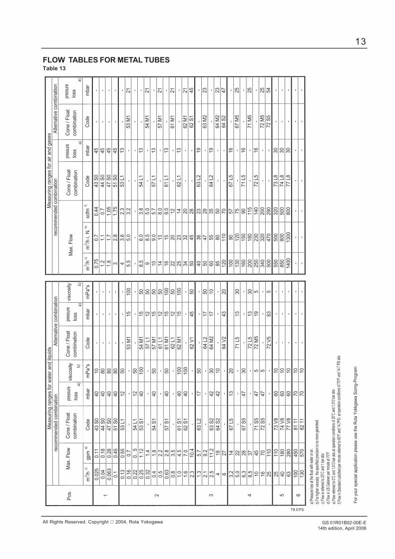
FLOW TABLES FOR METAL TUBESTable 13
Measu
ring r
an
ges
for
wate
r and li
quid
s
M
easu
ring r
an
ges
for
air a
nd g
ase
s
reco
mm
ended c
om
bin
atio
n
Alte
rnativ
e c
om
bin
atio
n
re
com
mended c
om
bin
atio
n
Alte
rnativ
e c
om
bin
atio
n
Max.
Flo
w
C
one / F
loat
com
bin
atio
n
loss
pr
essu
re
a)
vi
scosi
ty - b)
a
) b)
M
ax.
Flo
w
a)
a
)
P
os.
m3/h
c)
gp
m d
) C
od
e
mbar
mP
a*s
C
ode
mbar
mP
a*s
m3/h
c)
m3/h
i. N
. e)
scfm
f)
Co
de
m
bar
Code
mbar
0.0
25
0.1
1
43 S
0
40
10
- -
-
0.7
5
0.7
0.4
4
43 S
0
45
- -
0.0
4
0.1
8
44 S
0
40
80
- -
-
1.2
1.1
0.7
44
S0
45
- -
0.0
63
0.2
8
47 S
0
40
80
- -
-
1.8
1.7
1,0
5
47 S
0
45
- -
1
0.1
0.4
5
51 S
0
40
80
- -
-
3
2.8
1.7
5
51 S
0
45
- -
0.1
3
0.5
5
53 L
1
12
50
- -
- 4
3.6
2.3
53 L
1
13
- -
0.1
6
0.7
-
- -
53 M
1
15
100
5.5
5.0
3.2
-
- 53 M
1
21
0.2
2
0.
5
54 L
1
12
50
- -
-
- -
- -
- -
-
0.2
5
1.1
2
53 S
1
40
100
54 M
1
15
50
6.5
6.0
3.8
54 L
1
13
- -
0.3
2
1.4
-
- -
57 L
1
12
50
9
8.5
5.0
-
- 54 M
1
21
0.4
1.8
54 S
1
40
50
57 M
1
15
50
10
9.0
5.7
57 L
1
13
- -
0.5
2.2
-
- -
61 L
1
12
50
14
13
8.0
-
- 57 M
1
21
0.6
3
2.8
57 S
1
40
50
61 M
1
15
100
16
15
9.0
61 L
1
13
- -
0.8
3.5
-
- -
62 L
1
12
50
22
20
12
- -
61 M
1
21
1.0
4.5
61 S
1
40
100
62 M
1
15
100
25
23
14
62 L
1
13
- -
1.6
7.0
62 S
1
40
100
- -
-
34
32
20
- -
62 M
1
21
2
2.3
10.4
-
- -
62 V
1
45
50
50
45
28
- -
62 S
1
45
1.3
5.7
63 L
2
17
50
- -
-
40
36
23
63 L
2
19
- -
2.1
9.2
-
- -
64 L
2
17
50
50
47
29
- -
63 M
2
23
2.5
11.2
63 S
2
42
30
64 M
2
17
10
60
55
35
64 L
2
19
- -
4
18
64 S
2
42
10
- -
-
85
80
50
- -
64 M
2
23
3
6
27
- -
- 64 V
2
43
20
120
110
70
- -
64 S
2
47
3,2
14
67 L
5
13
20
100
90
57
67 L
5
16
- -
5,0
22
- -
- 71 L
5
13
30
130
120
75
- -
67 M
5
25
6,3
28
67 S
5
47
30
- -
-
160
150
90
71 L
5
16
- -
8,5
37
- -
- 72 L
5
13
30
200
180
115
- -
71 M
5
25
10
45
71 S
5
47
5
72 M
5
19
5
250
230
140
72 L
5
16
- -
16
70
72 S
5
47
5
- -
-
340
320
200
- -
72 M
5
25
4
25
110
- -
- 72 V
5
63
5
500
470
290
- -
72 S
5
54
25
110
73 V
8
60
10
- -
-
550
500
320
73 L
8
30
- -
40
180
74 V
8
60
10
- -
-
850
800
500
74 L
8
30
- -
5
63
280
77 V
8
60
10
- -
-
1400
1300
800
77 L
8
30
- -
100
450
81 1
1
70
10
- -
-
- -
- -
- -
- 6
130
570
82 1
1
70
10
- -
-
- -
- -
- -
-
T8.EPS
Cone / F
loat
com
bin
atio
nlo
ss
pres
sure
vi
scosi
tylo
ss
pres
sure
loss
pres
sure
C
one /
Flo
at
com
bin
atio
nC
one / F
loat
com
bin
atio
n
a) P
ress
ure
loss
at t
he fl
oat w
ith w
ater
or a
ir.
b) F
or h
ighe
r visc
osity
the
spe
cifie
d pr
ecisi
on is
no
mor
e ga
rant
eed.
c) F
low
is re
ferre
d to
20°
C an
d 1
bar a
bs
d) F
low
in U
S G
alon
en p
er m
inut
e at
70°
F
e) F
low
refe
rred
to 0
°C a
nd 1
.013
bar
abs
at o
pera
tion
cond
itions
of 2
0°C
and
1,01
3 ba
r abs
f) F
low
in S
tand
ard
cubi
cfee
t per
min
ute
refe
rred
to 6
0°F
and
14,7
PSI
at o
pera
tion
cond
itions
of 7
0°F
und
14,7
PSI
abs
For
your
speci
al a
pplic
atio
n p
lease
use
the R
ota
Yokk
gaw
a S
izin
g-P
rogra
m
GS 01R01B02-00E-E14th edition, April 2006
14
All Rights Reserved. Copyright 2004, Rota Yokogawa
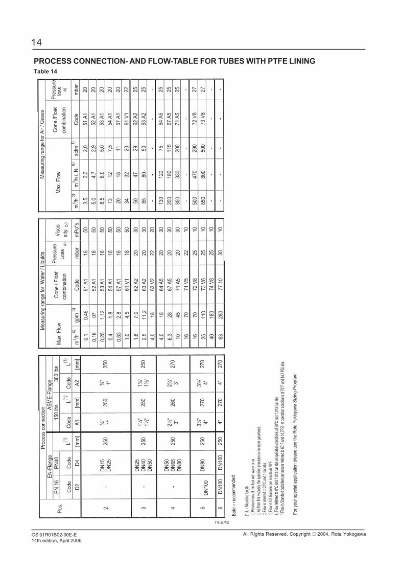
PROCESS CONNECTION- AND FLOW-TABLE FOR TUBES WITH PTFE LININGTable 14
Pro
cess
co
nn
ect
ion
Me
asu
rin
g r
an
ge
fo
r W
ate
r /
Liq
uid
s
M
ea
surin
g r
an
ge
fo
r A
ir /
Ga
ses
EN
-Fla
nge
A
SM
E-F
lange
PN
16
PN
40
150 lb
s 300 lb
s
Code
Code
L(1
) C
ode
L(1
) C
ode
L(1
)
Max.
Flo
w
Co
ne
/ F
loa
t-
com
bin
atio
n
Pre
ssu
re-
Lo
ss
a)
V
isco
-
sity
b
)
M
ax.
Flo
w
C
on
e /
Flo
at-
com
bin
atio
n
Pre
ssu
re
loss a
) P
os.
D2
D4
[mm
] A
1
[mm
] A
2
[mm
]
m3/h
c)
gp
m d
) C
od
e
mbar
mP
a*s
m3/h
c)
m3/h
i. N
. e)
scfm
f)
Co
de
m
bar
0,1
0,4
5
51 A
1
16
50
3,5
3,3
2,0
51 A
1
20
0,1
6
07
52 A
1
16
50
5,0
4,7
2,9
52 A
1
20
0,2
5
1,1
2
53 A
1
16
50
8,5
8,0
5,0
53 A
1
20
0,4
1,8
54 A
1
16
50
13
12
7,5
54 A
1
20
0,6
3
2,8
57 A
1
16
50
20
18
11
57 A
1
20
2
- D
N15
DN
25
250
¾“
1“
250
¾“
1“
250
1,0
4,5
61 V
1
18
50
34
32
20
61 V
1
22
1,6
7,0
62 A
2
20
30
50
47
29
62 A
2
25
2,5
11,2
63 A
2
20
30
85
80
50
63 A
2
25
3
- D
N25
DN
40
DN
50
250
1¼
“ 1½
“ 250
1¼
“ 1½
“ 250
4,0
18
63 V
2
22
20
-
- -
- -
4,0
18
64 A
5
20
30
130
120
75
64 A
5
25
6,3
28
67 A
5
20
30
200
180
115
67 A
5
25
10
45
71 A
5
20
30
350
330
200
71 A
5
25
4
- D
N50
DN
65
DN
80
250
2½
“ 3“
260
2½
“ 3“
270
16
70
71 V
5
22
10
-
- -
- -
16
70
72 V
8
25
10
500
470
290
72 V
8
27
25
110
73 V
8
25
10
850
800
500
73 V
8
27
5
DN
100
DN
80
250
3½
“ 4“
270
3½
“ 4“
270
40
180
74 V
8
25
10
-
- -
- -
6
DN
100
DN
100
250
4“
270
4“
270
63
280
77 1
0
30
10
-
- -
- -
(1) L
= M
ount
ing le
ngth
a) P
ress
ure
loss a
t the
float
with
wat
er o
r air.
b) A
s fro
m th
is vis
cosit
y the
spec
ified
prec
ision
is n
o m
ore
gara
ntee
d.
c) F
low is
refe
rred
to 2
0°C
and
1 ba
r abs
d) F
low in
US
Galon
en p
er m
inute
at 7
0°F
e) F
low re
ferre
d to
0°C
and
1.0
13 b
ar a
bs a
t ope
ratio
n co
nditio
ns o
f 20°
C an
d 1,
013
bar a
bs
f) F
low in
Sta
ndar
d cu
bicfe
et p
er m
inute
refe
rred
to 6
0°F
and
14,7
PSI
at o
pera
tion
cond
i tions
of 7
0°F
und
14,7
PSI
abs
T9.EPS
For
your
speci
al a
pplic
atio
n p
lease
use
the R
ota
Yokk
gaw
a S
izin
g-P
rogra
m
Bold
= r
eco
mm
end
ed

GS 01R01B02-00E-E14th edition, April 2006
15
All Rights Reserved. Copyright 2004, Rota Yokogawa
TEMPERATURE GRAPHS FOR RAMC METAL DESIGN, STANDARD AND Ex-i
The temperature graphs are reference values for size DN100. They may be influenced negative by dammed heat, external heatsources or radiated heat and influenced positive for smaller sizes.Insulation means rock wool between tube and indicator.Units with electronic transmitter can show the temperature of the internal transmitter on the display or HART-type can show andsupervise the internal temperature by HART-communication.Units with PTFE lining are usable up to 130°C.For units with explosion proof certification the temperature limits according the certificate of conformity must be regarded (see alsopage 4 and 5).The minimum ambient temperature for indicators is -25°C except units with option /KF1 (lower temperatures on request).
T10.EPS
0
50
100
150
200
250
300
350
400
20 30 40 50 60 70 80 90
Ambient temperature [°C]
max p
rocess t
em
pera
ture
[°C
]
w ithout option /A16with option /A16 and insulationwith option /A16, no insulation
0
50
100
150
200
250
300
350
400
20 30 40 50 60 70
Ambient temperature [°C]
max p
rocess t
em
pera
ture
[°C
]
w ithout option /A16with option /A16 and insulationwith option /A16, no insulation
-200
-150
-100
-50
0
-25 -20 -15 -10 -5 0
Ambient temperature [°C]
min
pro
cess t
em
pera
ture
[°C
]
Low temperature curve
with option /A16 and insulation
0
20
40
60
80
100
120
20 30 40 50 60 70
Ambient temperature [°C]
max. p
rocess t
em
pera
ture
[°C
]
fig. 6a RAMC : - type 90 / 91
- only with indicator
fig. 6b RAMC : - type 90 / 91
- with limit switches
- with electronic transmitter
fig. 6d RAMC : - type 90 / 91
- with or without limit switches
- with or without electronic transmitter
fig. 6c RAMC : - type 66
- with or without limit switches
- with or without electronic transmitter
GS 01R01B02-00E-E14th edition, April 2006
16
All Rights Reserved. Copyright 2004, Rota Yokogawa
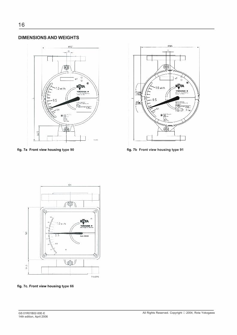
DIMENSIONS AND WEIGHTS
fig. 7a Front view housing type 90 fig. 7b Front view housing type 91
T12.EPS
fig. 7c. Front view housing type 66
T13.EPS
GS 01R01B02-00E-E14th edition, April 2006
17
All Rights Reserved. Copyright 2004, Rota Yokogawa
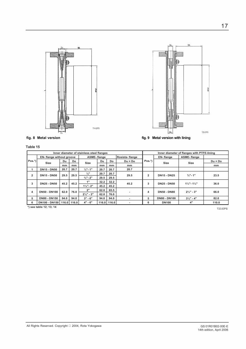
fig. 8 Metal version fig. 9 Metal version with lining
T14.EPS
Do
Du T25.EPS
Rosista- flange EN- flange ASME- flange
Du Do Du Do Du = Do Du = Do
mm mm mm mm mm mm
1 DN15 - DN50 20.7 20.7 ½"- 1" 20.7 20.7 20.7
½" 20.7 20.7
¾"- 2" 29.5 29.5
1" 32.2 32.2
1¼"- 2" 45.2 45.2
2" 62.0 65.5
2½" - 3" 62.0 76.0
5 DN80 - DN150 94.0 94.0 3" - 6" 94.0 94.0 - 5 DN80 - DN100 3½" - 4" 82.0
6 DN100 - DN150 116.0 116.0 4" - 6" 116.0 116.0 - 6 DN100 4" 110.0
*) see table 12; 13; 14
1¼"- 1½"
2½" - 3"
23.5
66.0
36.0
4 DN50 - DN80
3 DN25 - DN50
2 DN15 - DN25
Inner diameter of flanges with PTFE-lining
Pos.*)Size Size
¾"- 1"
DN25 - DN503
2 DN15 - DN50
4 DN50 - DN100 62.0 76.0
45.2 45.2 45.2
-
29.5
Inner diameter of stainless steel flanges
Pos.*)Size Size
EN- flange without groove ASME- flange
29.5 29.5
T23.EPS
Table 15
GS 01R01B02-00E-E14th edition, April 2006
18
All Rights Reserved. Copyright 2004, Rota Yokogawa
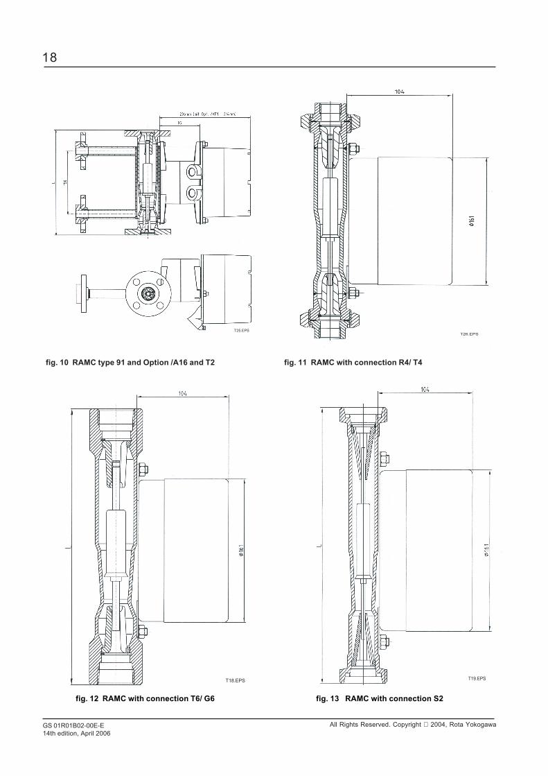
fig. 10 RAMC type 91 and Option /A16 and T2 fig. 11 RAMC with connection R4/ T4
fig. 12 RAMC with connection T6/ G6 fig. 13 RAMC with connection S2
T25.EPS
T19.EPST18.EPS
T26.EPS

GS 01R01B02-00E-E14th edition, April 2006
19
All Rights Reserved. Copyright 2004, Rota Yokogawa
Table 16 Diameter for connection sizes S4
Table 17 Weights
T22EPS
Weight / kg
3 - 51
2
3
Position *)
4
5
6
3 - 5
6.5 - 8
8.6 - 11
13 - 16
17 - 20
*) see table 12;13,14
T20.EPS
fig. 14 RAMC with connection S4
Position*)
Size[mm]
di[mm]
da[mm]
1
2
3
4
5
DN25 / 1´´DN32
DN40 / 1-1/2´´
363636
50.550.550.5
DN25 / 1´´DN32
DN40 / 1-1/2´´
*) see table 12;13,14
363636
50.550.550.5
DN50 / 2´´DN65
3´´DN100 / 4´´
47,8 6472.172.1
9191
97.6 119T21.EPS
GS 01R01B02-00E-E14th edition, April 2006
20
All Rights Reserved. Copyright 2004, Rota Yokogawa
Manufactured by:ROTA YOKOGAWARheinstr. 8D-79664 WehrGermany
RotameterTM is a trademark of Rota Yokogawa GmbH & Co. KG, a subsidiary of Yokogawa Electric Corporation, Japan. In the United Kingdom RotameterTM is a trademark of Emerson Electric Co.