General Electric Modern Longfellow Grandfather Clock...
64
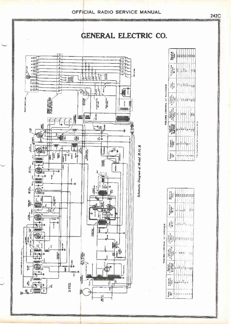
OFFICIAL RADIO SERVICE MANUAL Supplement No. 2 242A GENERAL ELECTRIC CO. General Electric Modern Longfellow Grandfather Clock -Radio Models H-91 and H -91-R SERVICE NOTES ELECTRICAL SPECIFICATIONS Voltage Rating 105-125 Volts Frequency Rating 50-60 Cycles or 25-40 Cycles Power Consumption 120 Watts Recommended Antenna Length 25-75 Feet Type of Circuit A C. Screen Grid Super -Heterodyne Number of Radiotrons 3 RCA -235, 1 UY-224, 3 UY-227, 2 RCA -247, 1 UX-280.---Total of 10 Number of Radio Frequency Stages One Type of First Detector Tuned Input Grid Bias Number of Intermediate Stages Two Type of Second Detector Power Grid Bias Type of Automatic Volume Control UY-227 (Controlling bias voltage on R. F. and I. F. stages by means of drop across resistor in plate circuit) Number of Audio Stages One (Push -Pull) Type of Rectifier Full Wave, UX-280 Type of Loudspeaker Dynamic with Special High Frequency Filter Wattage Dissipation in Loudspeaker Field Ten Undistorted Output Four Watts PHYSICAL SPECIFICATIONS Height 78 Inches Depth 14,14 Inches Width 1712 Inches Weight (Packed for Shipment) 205 Pounds Weight (Alone) 136 Pounds Packing Case Dimensions 8112 Inches x 21Y4 Inches x 19 Inches INTRODUCTION General Electric Radio, Models H-91 and H -91-R are ten tube, Super -Heterodyne type radio receivers incorporated in the cabinet of a massive electric Grandfather dock. Mechanical and electrical excellence together with the beauty of fine period furniture characterize this instru- ment. Model II -91 is a straight radio receiver and model H -91-R is of the remote control type. Ten Radiotrons are used, three RCA -235 as R. F., and I. F. stages one UY-224 as first detector, three UY-227 as oscillator, automatic volume control and 2nd detector; two RCA -247 as the power out- put stage and one UX-280 as the rectifier. These instruments, with the exception of the cabinet are similar to the model H-51 and H -51-R except than an automatic volume control tube and Radiotrons RCA -235 and RCA -247 in the R. F., I. F. and Power stages, have been included. For service data other than on the remote control unit that is applicable to vertical operation and on the automatic volume control circuit, reference should be made to the Service Notes already issued on the Model H-51 and H -51-R.
Transcript of General Electric Modern Longfellow Grandfather Clock...

OFFICIAL RADIO SERVICE MANUALSupplement No. 2 242A
GENERAL ELECTRIC CO.
General Electric Modern LongfellowGrandfather Clock -Radio
Models H-91 and H -91-R
SERVICE NOTES
ELECTRICAL SPECIFICATIONSVoltage Rating 105-125 VoltsFrequency Rating 50-60 Cycles or 25-40 CyclesPower Consumption 120 WattsRecommended Antenna Length 25-75 FeetType of Circuit A C. Screen Grid Super -HeterodyneNumber of Radiotrons 3 RCA -235, 1 UY-224, 3 UY-227, 2 RCA -247, 1 UX-280.---Total of 10Number of Radio Frequency Stages OneType of First Detector Tuned Input Grid BiasNumber of Intermediate Stages TwoType of Second Detector Power Grid BiasType of Automatic Volume Control UY-227(Controlling bias voltage on R. F. and I. F. stages by means of drop across resistor in plate circuit)Number of Audio Stages One (Push -Pull)Type of Rectifier Full Wave, UX-280Type of Loudspeaker Dynamic with Special High Frequency FilterWattage Dissipation in Loudspeaker Field TenUndistorted Output Four Watts
PHYSICAL SPECIFICATIONSHeight 78 InchesDepth 14,14 InchesWidth 1712 InchesWeight (Packed for Shipment) 205 PoundsWeight (Alone) 136 PoundsPacking Case Dimensions 8112 Inches x 21Y4 Inches x 19 Inches
INTRODUCTIONGeneral Electric Radio, Models H-91 and H -91-R are ten tube, Super -Heterodyne type
radio receivers incorporated in the cabinet of a massive electric Grandfather dock. Mechanicaland electrical excellence together with the beauty of fine period furniture characterize this instru-ment.
Model II -91 is a straight radio receiver and model H -91-R is of the remote control type. TenRadiotrons are used, three RCA -235 as R. F., and I. F. stages one UY-224 as first detector, threeUY-227 as oscillator, automatic volume control and 2nd detector; two RCA -247 as the power out-put stage and one UX-280 as the rectifier.
These instruments, with the exception of the cabinet are similar to the model H-51 and H -51-Rexcept than an automatic volume control tube and Radiotrons RCA -235 and RCA -247 in the R. F.,I. F. and Power stages, have been included. For service data other than on the remote control unitthat is applicable to vertical operation and on the automatic volume control circuit, referenceshould be made to the Service Notes already issued on the Model H-51 and H -51-R.

4 -G
AN
G C
ON
DE
NS
ER
18-
330
......
......
......
......
..4.
S W
OO
400
F
h04,
0.LI
NK
RC
A -
235
F
CO
UP
LED
CIR
CU
ITR
F00
-221
11.1
.55
;17
745
MIA
FO
745
AA
FO
600
011
,OS
C
_r3.
F40
/-7
,7
NE
D
ALL
GR
OU
ND
SR
AE
10
FR
AM
E
ELE
CT
RIC
CLO
CK
105-
050,
10-6
0 'A
. C.
IL_
FU
SE
PO
WE
RT
RA
NS
FO
RM
ER
3.5
0 0 011
0 V
. 0 0 012
00.
100
-r-1
- 0.
5 W
O
FD
.
TO
ALL
HE
AT
ER
S,
RC
A -
247
FIL
AM
EN
TS
AN
D P
ILO
T L
AM
P.
0 0 .22>
-- 3
5011
.707
AL
DlM
ED
.
2.M
FO
. 2504
'(1
.0
poo
k
y/1
.,---
4o..
3415
n 15
VF
W* FIL
TE
R /
RE
AC
TO
R18
H.
12,2
241.
! DE
TE
CT
OR
40,0
130.
11.
CO
PP
ER
015
CB
ET
WE
EN
C01
15
T R
041
ft01
500n0
0
rD .
LOC
A -
01S
1A11
1"
SW
ITC
H
EC
U 2
85(1
..vI
F A
mp
3911
4i41
11
0 01.0
0
RC
A 2
352'
.° IF
A1.
45
39n;
.4
4 I
51.
5
14.1
0011
INT
ER
SIA
GE
TR
AN
SF
OR
ME
R -
-
002^
31A
FD
31A
FD
.
IMFD.
PU
SH
-PU
LLP
OW
ER
AM
PLI
FIE
R
924
OU
TP
UT
IR A
NS
foR
m E
R
6101
1T
OT
AL
111 Coi
f
FIE
LDC
OIL
Av.
1330
1140
IL
1555
. m20
0051
.
R F
CH
OK
E80
fl,
.o0o
74 5
uF
110,
000
IL
1.0M
FD
10,0
0011
211.
DE
TE
CT
OR 11
9 M
DA
FD
1300
na.o
is
TO
NE
CO
NT
RO
L40
,000
51
26 Ai
140i
,
CH
OIC
E
8011
UY
-227
0 C
. 0 AZ
:1 02400
WA
R).
VO
LUM
EC
ON
TR
OL.
,
40,0
00
500,
000n
0.1
ME
D IC
500,
000.
n,
-Sch
emat
ic D
iagr
am o
f M
odel
H-9
1
2 4
FIL
AM
EN
T.
TR
AN
SF
OR
ME
R
- 0.
5M
FO
.
000.
AU
200
0002
AM
TO
rito
ut
21.1
5,1.
1f1
004
4.11
520
t000
2022
111
12,1
10 w
er-,
,
Lug V
tr
(
r
A.0
052.
I,0^
110.
1{,0
0nt
02 A
lt W
att..
0515
1 1.
1..1
1141
155o
011
thte
R
IN 1
11V
2011
0,0(
2201
1201
4
eel 1
6.1
42:
AE
A 1
2lt
Sitl
IALT
On
3010
0.11
740
1,
tato
t1-
ctor
i1-
1fr
.111
000
%
I
(004
1113
0A
at3
c
VO
LUM
E C
oNT
Roi
, vl M
INIM
( M
Sche
mat
ic D
iagr
am o
f M
odel
H -
91-R
Rad
io-
27
Ila th
ode
Ill,.
,,,t.
5011
5
Cat
hode
or F
Ran
lont
to le
mlro
lG
rid V
olta
I lat
itude
or ,1
0..,.
Ilu
Ser
rerk
1:r
idN
aito
1 al
loal
aao
-n i
or 1
dn
It. 1
%I"
tr"
Rio
t.Ilt
srnt
Se
/ow
n G
ridC
-eur
eti
orF
ilam
ent
Vol
t.
1 5 6 I
.0 10-
8..0 0 0.
0
15 110
- -
04.
- _ 11
1.1
I I ,
-
I
.110 , .
"
till
216
,
210
,..,. -
.II.
0 -52.
2la 0-
0
12
0 --22 2.
2o
500
2.2
lIlt
0010
,..-
-O
S
- -
--C
V -
22
- . 2,
2-
7 _3
400
0511
00.
Dl 5 M
oe
'5 .5
fRA
MO
R11
1005
1011
110.
1
1161
131
0111
1111
1l
tiliM
aiar
t 511
10.1
.61
.101
1 09
0800
1. 0
0114
1111
,11
jri..
f C?
(
5.00
.000
a
0.11
010.
414
.181
0115
v013
66 1
0111
101.
0,70
04
2010
11
VO
LUM
E C
ON
TR
OL
4 r
NIA
1.5
10.
1
OW
LO
OP
H'I'
''''':
No.
l''A
t7::'
Vel
laT
eCfC
ve"I
'G
rid V
olta
tr:';
r5.1
1.,"
*?:1
1JV
olta
nr'lf
..":1
.;:::"
;I::"
'5
alt.
1.14
1r0.
."^'
&N
oon
Grid
Cur
rent
/bal
er o
rF
ilato
rtal
lV
olta
1 2 3 $
IS.0
127
I,
,,-,
223
1001
$2.
2--
00
2.1
6.5
6.5
400.
2 5.0-
02.
1-
- 0
0201
417$ 70
223
210
25 235
-21
5
---li
----
2.2
4.5
2.5
2.2
2020
II-
2.2
0-
_0
I22
-I
22
2.1
- -
12
--
24$
2511
00 602.
2 1
12.
3
Vol
our
11.
2101
Au1
toe
.....
ner
10 r
fret
eit.
r

.000
740
ME
D.
.025
MO
D.
YE
LLO
W
TE
RM
INA
L
ST
RIP
1
hp'
YE
LLO
W W
TN
-RE
D T
RA
CE
R
RE
D A
ND
.'S
LAC
K
TO
NE
CO
NT
RO
LR
EA
CT
OR
RE
D W
ITH
YE
LLO
W/R
AC
ER
RIO
AN
DI A
CK
--.,.
/
TO
t"...
RU
.
GR
OU
ND
TO
FR
AM
E
3AP
I.E
.T
RA
NS
.
BLUE
\Nvf
LNW
ITH
RIO
TR
AC
ER
0024
MF
D.
I
efi H
4
VO
LUM
E
CO
NT
RO
L',,,
RE
D40
000n
-4-G
RE
EN
-""'
TO
S. P
. U. -
411-
YE
LLO
W
\B
Y-P
AS
SC
ON
DE
NS
ER
ato
1111
00
GA
M W
ITH
0 W
RE
D /R
AC
ER
aA
.-
Rj
Ir":
1/1
'4C
1-2
1;'
,..0)
Wrw
iTH
VIE
C/T
R A
$1.5
Lci-
sKN
ON
ST
TIN
CO
NE
RIIV
4iS
t,
LOC
AL
-DIS
TA
NT
TO
NE
ST
AT
ION
,-' S
WIT
CH
CO
NT
RO
L/S
ELE
CT
OR
IL, I
F
TR
AN
S
TO
DIA
LLA
MP .er.
wol
ALA
/RA
CE
R
,:-N
ftLO
WW
iTN
-11
IHIR
AC
RA
SIA
CH
ET
,CO
vER
IDS
PA
GN
TT
I-C
OvE
RE
AL, AID
;YE
LLO
W
..,..,
.
Ifif
\P
..Y
ELL
OW
R.N
..B
US
24J.
DE
TE
CT
OR
TE
RM
INA
L,,'
,g,..
E.
rN..,
., \
RID
TIIR
CE
R."
' lA
Y R
.F
Rer
F.
CH
OK
ES
TR
IP/
1N
ryttl
Ow
-wri.
NE
DT
RA
CiR
/k
-"41
"-..-
----
-'P
LAT
E C
OIL
rr
18.0
6 a
to,0
06n.
1 10
,000
rt
14.3
00 A
2.0
00A
2000
A -
.500
1AS
LAC
K A
ND
SLA
CK
IND
CR
OW
N A
RO
DR
OW
N A
ND
SLA
CK
SLA
CK
AN
DW
HIT
EV
. 0: .
.A,,
RIO
GA
HM
GU
MP
MK
AN
D P
INK
SR
Ow
NA
ND
MA
CK
NO
RIO
eE
40.0
0011
-St..
4.5
MM
ES
.G
RO
UN
DR
rr-T
O FR
AM
E
MM
FO
MO
W
GR
OU
ND
TO
FR
AM
E
C.R
EE
NA
NT
TH
RE
DT
RA
.Ce
ED
AN
ON
YC
LLO
RE
D.N
D,L
LLO
W
Wir
ing
Dia
gram
of
Mod
el H
-91
Rec
eive
r A
ssem
bly
ILK
DE
TE
CT
OR
/CO
IL
OS
CIL
LAT
OR
CO
ILS
-745
MIM
ED
.
6 .111
1?.
7'
II
'1.0
ME
D.
2
INT
ER
NA
L C
ON
NE
CT
ION
S O
FS
YP
AS
S C
ON
DE
NS
ER
S
62.1
OS
CIL
LAT
OR
TR
IMM
ING
CO
ND
EN
SE
R
BY
-PA
SS
CO
ND
EN
SE
RS 01
,
FO
.
40G
OM
M A
NT
EN
NA
TO
S.P
.U.
TE
RM
INA
L S
TR
IP
O

745
MM
FD
.
Ella
TE
RM
INA
LS
TR
IP3.
YE
LLO
W W
ITH
..--R
ED
TR
AC
ER
SP
LIC
E-,
RE
D A
ND
8 A
CK
-,,,
GR
OU
ND
TO
FR
AM
E
jW36
01.6
TR
AN
S.
BLUE
**,..
-yeL
LON
.HIT
HR
ED
TR
AC
ER
0024
ME
D.-
-
TO
S.P
.U. fi
24.0
1.F
.T
RA
NS
TO
NE
CO
NT
RO
L
IET
I.F
.T
RA
N',
iwY
ELL
OW
WIT
HR
pNR
AC
ER
SE
AG
NE
TT
.CO
YE
RI
iPA
GN
ITT
I:CO
VE
RE
bUS
BU
S
YE
LLO
W W
I
GR
EE
NA
CE
TR
Rk
TO
0.0W
7WIT
AR
ED
NT
A A
AR
NE
TT
IAC
ON
ER
ED
4
...
.//fi
-vc3
30,.,
WIT
H,
.2,
9, D
ET
EC
TO
R `
,TE
RM
INA
L,0
1111
0WIT
.RE
TI,
11\
RO
D T
RA
CE
R`
' i S
Y R
.F.
R.F
. CH
OK
E-S
TR
IP/
i',,
,aLL
OW
WiT
N.R
EO
.TR
AC
iRs.
2`...
PLA
TE
CO
IL
TO
A.U
.C.
16,0
00IL
I0,0
0011
.it0
,060
.n.
I4,3
00 IL
i000
1120
00.0
'500
n(7
01L
NE
AT
ER
AR
CH
AN
DB
LAC
K A
ND
BR
OW
N A
ND
DR
OW
N A
ND
BLA
CK
.B
LAC
K A
ND
WH
ITE
BR
OW
NT
RA
NS
FO
RM
ER
RE
DG
RE
EN
GR
EE
NP
INK
AN
D P
INK
BR
OW
NA
ND
BLA
CK
AN
D R
ED
RE
D W
HO
.-Y
ELL
OW
TO
LOC
AL
-DIS
TA
NT
ST
AT
ION
DIA
L S
WIT
CH
/, SE
LEC
TO
RLA
MP
,
40,0
0011
GR
EE
N A
ND
AW
E
4.5
MM
FD
.G
RO
UN
D4.
1.4.
,/,-
TO FR
AM
E
745_
,M
MF
D.."
`YE
LO
W
111.
11
40,0
001;
1.
,E0A
AR
EN
VA
NO
0
MO
N. w
nS R
ug T
RA
CE
R
IRO
wN
IRO
wN
AR
ELl
owIT
AN
RE
D-T
RA
CIR
GR
IEN
4.17
.RE
DA
IRA
CE
R
RE
DN
AN
DA
YE
LLO
W
RE
O.N
D-Y
eLLo
w
8U5
.WIT
H.R
EO
TR
AC
ER
TH
RE
DT
RA
CE
R
YE
LLO
W
YE
LLO
W
BU
S
(IT
DE
TE
CT
OR
CO
IL
OS
CIL
LAT
OR
CO
ILS
..745
MM
FO
.
OS
CIL
LAT
OR
TR
IMM
ING
CO
ND
EN
SE
R
BY
-PA
SS
CO
ND
EN
SE
RS
67
0.1
6iF
p.0
°SIR
ED
,
3'T
ON
ED
.
2
INT
ER
NA
L C
ON
NE
CT
ION
S O
FIIT
-PA
SS
CO
ND
EN
SE
RS
GR
OU
ND
AN
TE
NN
A
400
MM
FD
.
Wir
ing
Dia
gram
of
Mod
el H
-91
-R R
ecei
ver
Ass
embl
y
,123
40.
0*T
OS
.P.U
.
ol..,
Titt
titt
TE
RM
INA
L S
TR
IP

INT
ER
NA
L C
ON
NE
CT
ION
S O
F A
.F. T
RA
NS
FO
RM
ER
S
-VE
ILO
W-- Co
2300
A
A-m
*BLU
E-R
ED
..---
BLA
CK
-IN
TE
RN
AL
CO
NN
EC
TIO
NS
OF
CA
PA
CIT
OR
PA
CK
7650
4%61
011
43
2T
OT
AL
TO
TA
L
BL4
111°
--R
ED
-AN
DC
K2
33
0.5
MF
D.
MF
D.
MF
D.
MF
D.
`BLU
E-
-RE
INT
ER
ST
AG
ET
RA
NS
FO
RM
ER
40.0
00
RC
A -
24r
LAC
NA
,
LAC
K -
-
OU
TP
UT
TR
AN
SF
OR
ME
R
GR
EE
NA
CK
BLA
ck
LAC
TO
RE
CE
IVE
R :4
0""'e
ttmA
SS
EM
BLY
4-P
HE
N
ID C
LOC
K
I
RE
SIS
TO
R B
OA
RD
CO
NN
EC
TIO
NS
- m
.0
CIE g
YE
LLO
W W
ITH
RE
D T
RA
CE
R
AC
K
KWI
RID
TR
AC
A.C
.INP
UT
PLU
G
Wir
ing
Dia
gram
of
Mod
'l H
-91
S. P
. U.
INT
ErI
NA
L C
ON
NE
CT
ION
S O
F P
OW
ER
TR
AN
SF
OR
ME
R
-KM
* W
IT o
r IL
E 0
4 R
AC
ER
-
5.5A
TO
TA
L
-11L
AC
,AN
D-R
D
DE
AC
K
N
gI
BR
OW
N-W
ITN
-GR
EE
NT
RA
CE
R...
IIIU
X-2
80 F
ILA
ME
NT
BR
OW
NA
DIT
H4R
EE
N-T
RA
CE
P-
----
--D
RO
WN
HE
AT
ER
S, F
ILA
ME
NT
SA
ND
DIA
L LA
MP
BR
OW
N
I3S
LAC
K-W
ITN
SLU
E-T
RA
CE
R
HIG
H V
OLT
AG
E
YE
LLO
W -
WIT
H -
RE
D -
TR
AC
ER
-....
50A
TO
TA
L
(LA
CK
-WrT
N-B
LUE
-TR
AC
ER
IN T
.RN
AL
CO
NN
EC
TIO
NS
OF
FIL
TE
R R
EA
CT
OR
TIO
GR
EIN
AT
1tA
CE
R
Kyy
rte
_ -'tfh
o, "r4C
ER
CA
-6474
.1.
4 D
TR
AC
EN
OP
ER
AT
ING
SW
ITC
H

INT
ER
NA
L C
ON
NE
CT
ION
S O
F A
.F. T
RA
NS
FO
RM
ER
S
-YE
LLO
W
2300
SX
-GR
EE
N
BLU
E-
-RE
D76
50.A
.61
0A. g
TO
TA
LT
OT
AL
giB
LUE
-A
ND
--R
ED
-AN
D--
pY
ELL
OW
BLA
CK
T=
:,
BLU
E-
INT
ER
ST
AG
ET
RA
NS
FO
RM
ER
RC
A -
247:
RE
D
RT
D
LAC
K-
LAC
K -
OU
TP
UT
TR
AN
SF
OR
ME
R
BLA
Ck
55A
CE
NT
ER
TA
PP
ED
RE
SIS
TO
R
BR
OW
N
RID
BL
AC
K
UX
-280
INT
ER
NA
L C
ON
NE
CT
ION
S O
f CA
PA
CIT
OR
PA
CK
RE
SIS
TO
R B
OA
RD
CO
NN
EC
TIO
NS
43
2
2
MF
D.
5
TO
CLO
CK
30.
5M
FD
.M
FD
i
upm
ot
kiffR
ITE
'4
250A
-
40.0
00A
18,0
00A
. 18,0
00A
tt
INT
ER
NA
L C
ON
NE
CT
ION
S
-BLA
CK
-WIT
H-R
ED
-TR
AC
ER
S.S
.ft T
OT
AL
-BLA
CK
AN
D -
RE
D
BLA
CK
icef
ELL
OW
WIT
H R
ED
TR
AC
ER
rnsV
ELL
O
At
LAC
K
BLA
CK
WIT
HR
ED
TR
AC
ER
vs?
LAR
GE
- T
ER
MIN
AL
A.C
. IN
PU
T P
LUG
Wiri
ng D
iagr
am o
f Mod
el II
-91
-R S
. P.
U.
6RE
D,
ELL
OW
LAC
OF
PO
WE
R T
RA
NS
FO
RM
ER
KB
RO
WN
-W
ITH
-G
RE
EN
-T
RA
CE
R_
ux-2
.3 0
FIL
AM
EN
T
BR
own-
wiT
H.G
RE
LN.T
RLa
rt-
BR
OW
N
HE
AT
ER
S, F
ILA
ME
NT
SA
ND
DIA
L LA
MP
BR
OW
NIB
LAC
K-W
ITH
-BLU
E-T
RA
CE
R-
3
HIG
H V
OLT
AG
E
YE
LLO
W -
WIT
H -
RE
D -
TR
AC
ER
50.n
TO
TA
L
BLA
CK
-W
ITH
-B
LUE
-T
RA
CE
R -
INT
ER
NA
LC
ON
NE
CT
ION
S O
FF
ILT
ER
RE
AC
TO
R
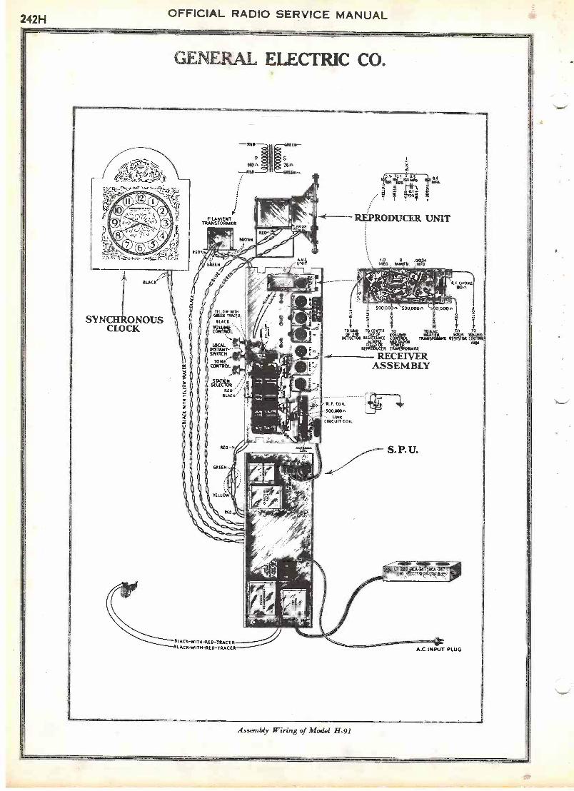
242H OFFICIAL RADIO SERVICE MANUAL
GENERAL ELECTRIC CO.
ISLACK
SYNCHRONOUSCLOCK
EN --
P
HOA .26A--RED
IFILAMENT
TRANSFORMER
BLACK -WITH -RED -TRACERLACK -WITH -RED -TRACER A.C.INPUT PLUG
REPRODUCER UNIT
NEE., 1161Z9). ,M
I 2
TDEECI`04RiNE
RECEIVERASSEMBLY
F. COIL
-500.030"UNK
CIRCUIT COIL
A. SOO,000 5...000'
CHOKEE10^
.11
Triknuaro-Potamet RESISTOR
ARM
S.P. U.
\ig-NO4NEAMEA.61.11'awIEN
Assembly Wiring of Model H-91
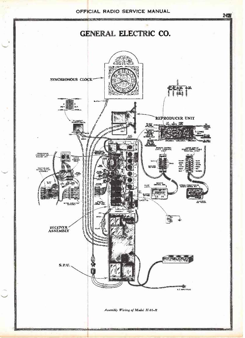
OFFICIAL RADIO SERVICE MANUAL2421
GENERAL ELECTRIC CO.
SYNCHRONOUS CLOCK
TRAT6FORNWIt.CONDENSER Ala.. ---REACTOR UNIT
SELECTOR ANDSETTING SUTTON
ASSEA.SLv
*BA ..Z5.7ittQ s
TRFAvola
"ISsTaINT°1'
RECEIVERASSEMBLY
S. P. U.
REMOTE CONTROLCABLE TERMINAL
STRIP
-21 at
Alc
REPRODUCER UNITalox
COIL
-0M`Con. --s,
Assembly Wiring of Model H -91-R
5-;
4/FA.C. INPUT PLUG
BtinITIA

LL
Coupler Can
Bla
ck/
Red
Shielded Lead
With Copper Tracer
Shieliel
Lead Wit
Out Tra
Black To Gnd. Post On
Receiver Shielded Lead
To Ant. Post On Receiver
Red to B4 250 Volts on
Receiver M
OD
EL
281
CO
NV
ER
TE
R ^
-
....d
...iV
ierA
V4P
ara:
42.7
a.a.
......
..aar
or.e
.a.v
......
.....g
r &
co.
n7_1Green
TABLE OF CONDENSERS AND RESISTORS
CONDENSERS
Cl,
.1-.1-.1 mfd.
C2,
.01 mfd.
C2,
.00025 mfd.
C4, Line Tuning Condenser
C5, Oscillator Series
Condenser
RESISTORS
R1, 100,000 Ohms
R2,
40,000 Ohms
R3,
7,500 Ohms
R4,
1,000 Ohms
R5, 8 Ohms
VOLUME CONTROL
Section A - 10,000 Ohms
Section B
50 Ohm
R2
R3
C4
Cl
Zmmomee:1. 237
R4
Yellow
AB
im=
1111
1111
1111
1111
1Nrda -
Tel
Cl
-4-
1-1 O

OFFICIAL RADIO SERVICE MANUAL278A
0a
1 0
JACKSON -BELL CO., LTD.A
Aav-
/
To
a
002
OO
0 o_S
"
?
J
*0047
C
CO
-J
O
02 07.0
01
227
r
t7/
2. 0
0 V
.
Nd4
Uli
.00Q
1/
I-
I
MO
DE
L 8

OFFICIAL RADIO SERVICE MANUAL 278C
.6-545I0 12 CODAPCP CAW", 00 0 001.?
0 4A kti AL /sago..5ifnAJ .(ite -.I- IVA-9.4.1444~x,e. 1 2 1.4.,c.
la' R.Ec BMA-AfeRE 0.1,0
JACKSON -BELL CO., LTD.
tu
-KA / 224
30 coo
224
245
3'
-77/ 214
)-1
a.
0co;'/ooe:',004Z /one;
CCU
01 245'
tesn
/42 date Ito fey
/44 Da- ,5-0
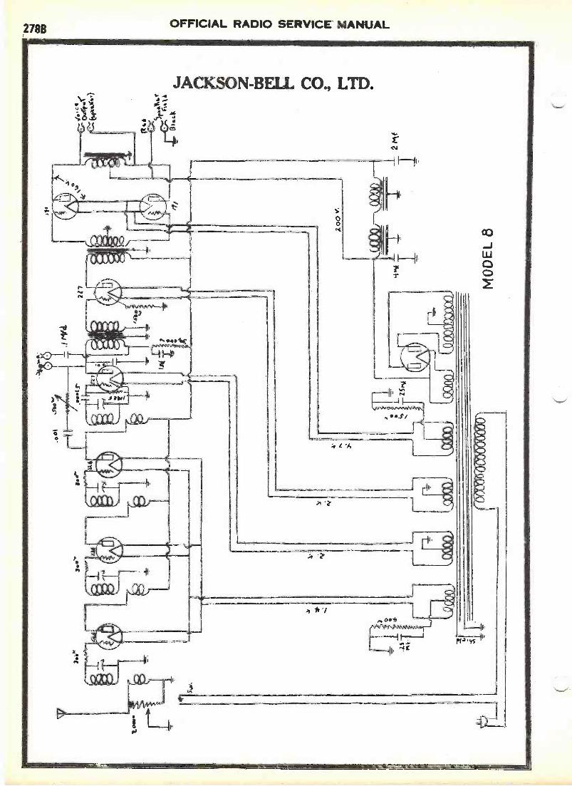
VOLTAGE AND CURRENT VALUES:
With the volume control at maximum, the following readings should beobtained with an allowable variation of 108: -
range.
R.F. Plate VoltageR.P. Screen Grid VoltageR.P. Grid BiasR.F. Plate CurrentR.F. Screen Current245 Plate Voltage245 Plate Current245 Bias VoltageDetector Screen Grid Voltage.Detector Piss VoltageDetector Plate CurrentDetector Plate Voltage
100
Th
2
2.2 mile approx..3 "
21023
405**
.1 mile (no signal in receiver)100...
Voltage readings were made with a 1000 ohm per volt meter. 250 volt
.The reeding here on a set analyser will show about 2 volts due tothe fact that the 2 meg. ohm resistor Is in series with the meter. To cheek gridvoltage, drop sore.e speaker divided by 2 will be the Approximate voltage appliedto grid. If plate cu oat ix about 25 mils and voltage *bout 220, it is safe toer.mie that the grid bias is O.K.
...Detector hie. reeding is taken at the overload point or an inoonlngsignal *more it generally reaches a maxima of 6 volts. With sere volume control,the reading here i. apiroximately 4 volts. This, of course. is not the true reed-ing, because resistance of volt meter becomes a parallel etreult, cutting down theresistance, and of ccuree. dropping the voltage. Reading taken in thie case waswith 10.000 ohm meter (1000 per volt. 10 volt aoale.)
...This reading is 'Object to considerable variation with metere ofvarious resistances. es the voltage at this point is measured through a 500,000 ohmresistor. The voltage at the opposite end of the resistor should be 220 volts.
TRANSFORMER VOLTAGES:
224 . 245 Filament on one eluding, 2.20 volts.280 Filament - 4.5High vo,tego minding. 315 each side of center tap.
RESISTANCE COLON CODE - CARBON RESISTORS.
1 Watt
10.000 ohms Brown with Slack bend, Orange Dot.30,000 - Orango with Black Bawd
500,000 " - Green with Bleak Band A Isilew Dot2 meg. - Bluu
2 Watt.
5,000 ohms - Green with Black Band and Fled Dot300 - P.P. Bias Resistor is wire wound.
RIXDITANCS, COIDR OHS - CARBON 113SISTORS.
3001100220030005000
100002000030000
1
1
2
100050000
1 WATT
Ohm - Wire Wound
" - Blue- Solid Red
Orange Black End-
- BrownRed
- Orange -meg - Red - Green
- Green Black- Brown- Purple- Brown -
- Green
ti
tt
It
It
ohmtt
it
If
Black
2 WATT
tl
If
11
- Red DotII at
- Orange DotIt
at
- Yellow
Green
at
fl
- Red- Orange "
5000 Ohm - Green with Black Band and Red Dot2200 " - Red300 " - R.F. Bias Resistor is Viire Wound.
RADIO FREQUENCY cgns.
Radio frequency coils in this Receiver arewound with 130, and 132 turns on the secondaries.The antenna coil has 132 turns, the second, thirdand detector coils have 130 turns.

0111
1111
1111
1
pS
WIT
C14
Aw
r
GN
P. I
7E7
300.
n.
7-7
3 00
030
,000
ti
X M
O"'
AT
[3 O
or 'o
r E
ppO
r A
LL P
IIIM
AR
It3.
Ar
2+ H
EA
TE
RS.
3o, 1
1.41
1
/0,0
a.
10,1
00 e
t.I
/1,6
00A
.W
onI..
.Y
rr.IM
SW
WW
1.4
Amu.
MO
DE
L 68
With the volume control at maximum, the following readings should be
obtained, with an allowable variation of 10i: -
R. F. Plate Voltage
1F)0
R. F. Screen Grid Voltage,
.75
R.
F. Grid Bias
2.5
R.
F. Plate Current,
2.5 M
First A.
F. Plate Current,
..
3}
M
First A.
F. Plate Voltage,
..
115
V
First A.
F. Bias,
5V
'45s Plate Voltage
225
V
'45s Bias,
50
V
'45s Plate Current,
30
M
Detector Screen Grid Voltage
50
V
Detector Bias
5V
Detector Plate Current,
2 M (No signal in Receiver)
Detector Plate Voltage,
100
4 or
,.
00
14
CO 0

OFFICIAL RADIO SERVICE MANUAL2 78E
z
LL
O
O
C
JACKSON -BELL CO., LTD.
00
___1151RTM-11-15-
0 0 0 s
g-9.919S.Lik
-FM 678 0
pri-)Uu2fu_9_suLuz,
t.,C)
Q.2
21F61
'an)
I
UI
O
dr*
6-1UsAittut,
_zy 6> a)
I I
L)
O
te
0
0
0 I

D.C. line 110 volts, voltages check as follows:-
R.F. Filament,
2 volts
R.F. Plate
90
"
R.F. Screen Grid,
60
"
R.F. Bias,
211
Detector Filament,
211
Detector Plate,
9C
"
Detector Bias,
10i
II
First Audio Filament,
2II
First Audio Plate,
90
ft
First Audio Bias,
2II
Push -Pall Filament,
2
Push -Pull Plate,
95
A
Push -Pull Bias,
12i
If
CARBON RESISTOR COLOR CODE.
ak Ohm - Wire Wound
1200
"- Blue
2200
It- Solid Red
3000
"- Orange
Black End
Red Dot
5000
"- Green
IIII
tlII
10000
"- Brown
"if
Orange Dot
20000
ft
- Red
-n
if
n
30000
II- Orange
-n
n-
nn
i-7,6
- Red
- Green
"Yellow
IT
- Green
- Black
n-
nn
1"
- Brown
-11
II- Green
"
2"
- Purple
1000 ohm - Brown
- Black.
"- Red
n
50000
"- Green
-ft
"- Orange
"
NOTE:
For a snort time, the 20,000 ohm is
solid black.
/IN
N 1
1111
1110
1.71
1,11
1111
111A
111
O I
AIL
_At
/I U
NA
El%
FI
V\
j
To
IVov
r
I 1
LI
1.-.
1
=3 DC
tJ
MO
DE
L69
D.C
.
I
VOLVric
.
I
Iof
I
t.. O00
CO-n

= 1
75 K
c.
, /1(C
LL
IO
k 1/4 21
01
Trans ilator
Oscillator
Oscilldor
Oscillator
Detector
Detector
Detector
4545
With volume control at maximum the following readings should be obtained with an
allowance of 10S for variation:-
I.F. Transilator and R.IP
Filament voltage
2 V.
I.P. Transilator and R.F
Plate voltage
245 V.
1.F. Transilator and fi.F
Screen grid voltage
120 V.
I.F. and R.F
Grid bias
2 W.
Grid bias
B W.
Filament voltage
2 V.
Plate Voltage
1E5 V.
Grid bias
4 V.
Filament voltage
P V.
Plate voltage
232 V.
Grid bias
5 V.
Filament voltage
Ei V.
Plate voltage
250 V.
'46
rrid bias
50 V.
'80
Filament voltage
49 V.
'90
Milliampere drain
DO M. per plate or a
total drain of
60 Mills.
10,000 s.
e
10 1
1,0.
isP
.
JAC
KSO
N-
BE
LL
SUPE
RH
EtE
RO
OM
E -
/YO
DE
L. 7
.9J.
H.H
.
.000
s
Csk
Q12
.0fI
SSZ
A0
a.1

/L
.4
I
I.F
= 1
75 K
c.
3ooc
f1.
7...0
0
44
27 5C .
With volumo control at maximum the following ruadinge should Do obtainod ml.th an
allowanco of 10% for voritions:-
I.F. Traneilutor and R.F
Filament Voltogo
2 V.
I.F. Transilator and R.F.... Plate Voltogo
245 V.
I.F. Traneilator and R.F.... Scroon Grid Voltogo
120 V.
Z.F. and R.F
Grid Bias
4 V.
Traneilator
Grid Bias
6 V
.Osoillator
Filamonb voltage
2 V.
Oscillator
Plato Voltogo
120 V.
Oscillator
Grid Bins
4 V.
Dotootor
Filamont Voltogo
2 V.
Dotootor
Plate Voltogo
255 V.
Dotootor
Grid Bias
6 V.
447
Filemont voltago
2/ V
..47
Plato voltage
250 V.
.47
Grid bins
16 V.
47
Space grid
176 V.
t.
'BO
Filqmont volt
ag44
V.
O'6
0Milllampore drain
30 M. por pinto or a
Ototal drain of
60 Mills.
I .5
- i I
----
---,
r---
_0.
4(-
,1)0
of ,-"!
tg&
L-
c,-
13
1 0,
0 C
0 S
I.
11
)2)
.', V
. Fkl
2.50
4-1
'
OX
)01,
-so
rnr
s,
2.5
=O
10,0
001E
RFC
4 M
O
4-1`
Ifi)
SC
.M
OD
EL
89
AL
.M1,
4_w
- o
wn
I'
"A
ION
LPI
PA
L"
-(

f->oo-va
e..13 111A -
I I
L
1A1 5179
130014
z/
1:13 1.11ti ViO
ci
S -P2. Z
LZ
SZ000
000'coogtno9
_Lao
10'11,0JOD
NO
.L
n.sZ
-t-009
Lz 009
1.4-8vo
Zoo
cico...))FioN
ILvom
ahal3
N 9_
00noz

0 Cr co 4..)
0 0
-10
Bo.
300
5\41
1 C
-14
.000
0500
005
.600
05
6" 2
7D
EIT
IZ
7.0
0025
27
-"-.
00i .
1
PIC
KU
P/
1:Y
E''.
5:
1
;1
:'
E..
----
R 1
7--
& D
E T
.1I'
. /e0
I-PO
RIZ
EIR
HI
Z.5
`I
q-e
IA
Q01
0 N
I,to
is
2 q
I
1!
I
ICN
EC
O1'
41
soo,
00z
0 0
4-
4/41
/vvv
vv,_
__II
6.1
0, 0
001O
,000
1-WO
N'M
AN
N
RC
L. 45
.
0 (T1
4
c
rG
L,.>
LK
Mac
s7.:\
ec
0v,
Vto
:\Ac0
s-rd
0. X
...h
MO
DE
L 8
45 S
Wa.
0 z pcm O
OFFICIAL RADIO SERVICE MANUAL326A
IIMMMNIMer
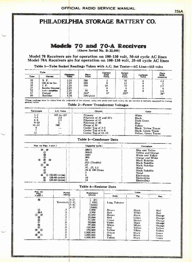
PHILADELPHIA STORAGE BATTERY CO.
Models 70 and 70-A Receivers(Above Serial No. B-22,000)
Model 70 Receivers are for operation on 100-130 volt, 50-60 cycle AC linesModel 70A Receivers are for operation on 100-130 volt, 25-60 cycle AC lines
Table 1 -Tube Socket Readings Taken with A.C. Set Tester -AC Line -115 voltsTube
FthussawtVolts
PlateVolta
ControlGridVolta
ScreenGridVolts
CathodeVolta
PlateMilli -
amperesType Circuit
35 R. F. 2.25 250 5 70 6 4.324 OSC & let Det. 2.25 250 8 12 8 .535 1. F. 2.25 250 21) 7(1 0 1.72735
Rectifier DetectorAudio modifier
2.252.25
...50
00
060
00
01.0
47 Output 2.25 240* 4* 255* 28*80 Rectifier 4.70 260/plate .. ...
*These readings must lie taken from the underside of the chassis, using test prods and leads unless the set checker is specially equipped fur testingpentode tubes.
Table 2 -Power Transformer Voltages
Terminals A.C. Volts Circuit Color
1-2 105 to 125 Primary White3-5 2.5 Filament of 24 and 35's Black6-8 2.5 Filament of 47 Dark Green9-10 5. Filament of 80 Blue
11-13 700 Plates of 80 Yellow4 Cenier Tap of 3-5 Black, Yellow Tracer7 Center Tap of 6-8 Black, Green Tracer
12 Center Tap of 11-13 Yellow, Green Tracer
Table .-Condenser DataNos. on Fills. I and 2 Capacity (mid.) Container
.00011
.00041
.0007
.003
Blue and YellowYellow and OrangeWhite and YellowOrange and White
@ 00 .01 Black Bakelite.015 (Double) Black Bakelite
® 00(is)
.05.05, .25, 1.5
Black BakeliteMetal
.09 & 200 Ohms Black Bakelite.5 Metal
6-1) (50-60 cycles) 6 Electrolytic(25-40 cycles) 10 Electrolytic
*) (25-40 cycles) 14 Electrolytic
Table 4 -Resistor DataNos. on Power
(ohms)ResistanceFigs. (watts)1 and 2
1
Color
Body Tip Dot
ii1 1-21 26)Terminals2 3 ll 850 Long Tubular3-4(11650f
14 -5 I 1060).5 1,000 Brown Black Red
QA .5 2,900 lied White Red@) .5 10,000 Brown Black Orange
25,000 Red Green Oranges+..5.55.
51,00070,000
GreenViolet
BrownBlack
OrangeOrange
5 99,000 White White Orange: .5 330,000 Red Yellow Yellow.5 490,M1 Yellow White Yellow()
CI 40. 5
.5
. 5
1,000,0002,000,0004,000,000
BrownRedYellow
BlackBlackBlack
GreenGreen(;reen
326BOFFICIAL RADIO SERVICE MANUAL
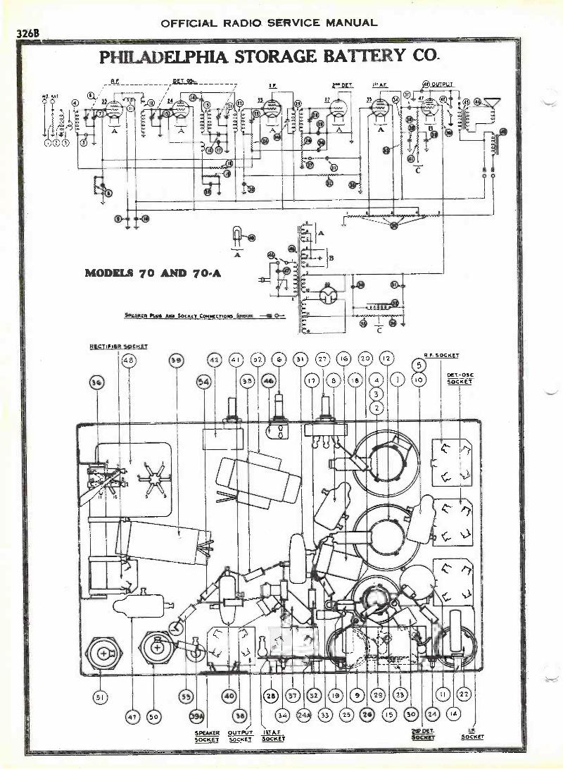
PHILADELPHIA STORAGE BATTERY CO_
RECTiFtut 5.ocKET
2
0
59
CD®54
SPEAKERSOCKET
I 1.7 A.E
SOCKET
0 "0 SOCKET
0 0 0 0 0 000
SOCKET
0E7.- OSCSOCKET
SOCKET
OFFICIAL RADIO SERVICE MANUAL326C
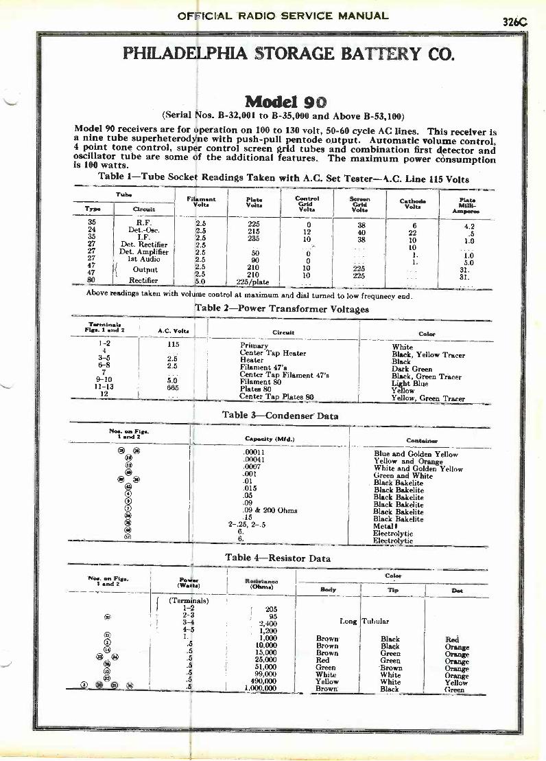
PHILADELPHIA STORAGE BATTERY CO.
Model 90(Serial Nos. B-32,001 to B-35,000 and Above B-53,100)
Model 90 receivers are for operation on 100 to 130 volt, 50-60 cycle AC lines. This receiver isa nine tube superheterodyne with push-pull pentode output. Automatic volume control,4 point tone control, super control screen grid tubes and combination first detector andoscillator tube are some of the additional features. The maximum power consumptionis 100 watts.
Table 1 -Tube Socket Readings Taken with A.C. Set Tester-k.C. Line 115 VoltsTube
FilamentVolts
PlataVolts
ControlGridVolta
ScreenGrid
VoltaCathode
VoltsPlateMilii-
AmperesType Circuit
3524352727274747SO
R.F.Det.-Osc.
I.F.Det. RectifierDet. Amplifier
1st AudioOutput{
Rectifier
2.52.52.52.52.52.52.52.55.0
225215235
5090
210210
225/plate
01210
. .
00
1010
384038
225225
6221010
1.1.
4.2.5
1.0
1.05.0
31.31.
Above readings taken with volume control at maximum and dial turned to low frequnecy end.
Table 2 -Power Transformer VoltagesTerminals
Figs. I and 2 A.C. Volta Circuit Color1-2 115 Primary White
4 Center Tap Heater Black, Yellow Tracer3-5 2.5 Heater Black6-8 2.5 Filament 47's Dark Green7 Center Tap Filament 47's Black, Green Tracer9-10 5.0 Filament 80 Light Blue11-13 665 Plates 80 Yellow12 Center Tap Plates 80 Yellow, Green Tracer
Noe. on Figs.I and 2
eOO0
Table 3 -Condenser Data
Capacity (Mid.)
.0001100041.0007.001.01015
.05
.09.09 dr 200 Ohms.15
2-.25, 2-.56.6.
Container
Blue and Golden YellowYellow and OrangeWhite and Golden YellowGreen and WhiteBlack BakeliteBlack BakeliteBlack BakeliteBlack BakeliteBlack BakeliteBlack BakeliteMetal IElectrolyticElectrolytic
Table 4 -Resistor Data
Noa. on Figs.I and 2 Power
(Watts) Resistance(Ohms)
Color
Body Tip Dot
(Terminals)1-2 2052-33-4
952,400 Long Tubular
4-5 1,2001. 1,000 Brown Black Red.5 10,000 Brown Black Orange.5 15,000 Brown Green Orange44)@ .5 25,000 Red Green Orange.5 51,000 Green Brown Orange.5 99,000 White White OrangeO .5 490,000 Yellow White Yellow.5 1,000,000 Brown Black Green

326DOFFICIAL RADIO SERVICE MANUAL
,1
PHILADELPHIA STORAGE BATTERY CO.
7; DET-o5c
PIIILCO MODEL 9 0
RECTIFIERSOCKET
68 1008048 , CI 0 0 0
SPEAKER DET,Am P.
SOCKET SOCKET SOCKET
DET.SOCKET
SPEAKER PLUG AMO SOCKITCOHNECTiONS SHOWN -MI 0-
I. F.
SOCKET

OFFICIAL RADIO SERVICE MANUAL326E
PHILADELPHIA STORAGE BATTERY CO.
Conoenser 3615 .05 Mfd.
PNarto.
Cond.Cap.Mfd.
LugsUs( d
WireReels.Ohms
WiringEnsis.-
-Alga
Cond.WiringLugs
3615-B .05 1-3-5 250 3-5 1-5
13615-C .05 1-5-7 250 5-7 1-5
3615-D .05 1-3-5 ... 1-5
1 3615-E .05 2-5 ... ...3615-F .05 2-3-5 ... 3-5
3615-G .05 5-8 ...- '
3615-H .05 3-5-8 '5-8
36154 .05 1-5-7 ...'
1-5
3615-K .05 3-5-8 250 3-5 5-8
3615-L .05 1-5 ...
3615-M .05 2-5-7 2-3
1-4
1-4
1-3
3615-N .05 1-4-7
3615-P .05 1-1-7 250 1-7
5-73615-R .05 1-5-7 2.10
3615-3 .05 1-4
3815-T .05 1-5-7 150 1-7 1-3
3615-U .05 1-5-7 1-7
3615-W .05 1-2-5
1-7
1-5
,1-:1
1-5
1-7
1-S
3615-X .05 1-2-5-7 150
3615-Y .05 1-2-5-7 1.10
3615 -AA .05 1-3-5-8
3615 -AB .05 1-4-7-8 1-1
3615 -AC .03 1-5-7-8 ... 1-7
3615 -AD .05 3-5-8 ... 3-3
3615 -AE .05 1-7-8 7-5
3615 -AF Twin .05 4-7-8 4-8 J: 7-8
3615 -AG .05 1-3-5 1-3
3615-AH .05 1-5 1-3
3615-AJ Twin .05 1-3-6-8 ... 1-3 & 1-6
3615 -AK .05 1-5-7-8 ... 1-7
Standard By -PassCondenser Data
The tables below list the various Philcostandard bypass condensers in blackbakelite containers. 'the drawing showsall possible lug arrangements and thetables list the lug numbers.
Condenser 3793 .015 Mfd..Cond. Lusa
WireWireResiOhmss.
Reds.'TwineLugs
- ICoed.Wiringlags
3793-B .015 44 ...379C3 -C .015 2-4 ... ... ...3793-D3793-E
.015 2-6 ...Ta in .015 1-5-7 ... ... 1.5 & 1-7
3793-F .015 5-7-8 ... .. 7-83753-G3793-11
.015 2-3-6 ... ... 2-8Twin .015 1-3-5 14 & 1-5
3793-J .013 2-5-7 ... ... 2-53793-K Twin .015 1-5-5-8 .. . . i- 15 & 1-53793-L Twin .015 5-7-8 ... ... 7-83793-M Twin .015 5-7-8 ... ... 5-8 & 7-8
Condenser 3903 .01 Mfd.
PartNo.
Cond.Cap.Mfd.
Lugs I WireReels.T.Tsed
I Ohms
Regis.WiringLugs
Cond.WiringLugs
3903-F .01 3-5 ... ... ...3903-G .01 2-4-7 ... ... 2-43903-H .01 lf-S ... . ...:i063=.F .01 - I :?#-Y-f--- ... ... 2-53903-K_39903-L
01 1-4-1-7 ... -1-7.01 3-5-8...... 3-5
390:1-M .01 4-7-8 ... 4-83903-N .01 3-5-8 ' 5-83903-P .01 2-5-7 ... ... 2-73903-11 .01 4-7-8 ...3903-8 Twin .01 1-5-7 ... 1-5 & 1-73903-'1' .01 5-7-8 ... 7-83903-1.:
_ __1-7
___.01 1-2-5-7 ...
3903-W .01 2-4-7' '
" '' 2-7
3903-X .01 3-5-8 3-8
3903-1. .01
Condenser 4989 .09 Mfd.3 5
fart Cond.No. Cap.
Mid.Lugs 11 'ire Reds. C:nnd.rsed Reels. Wiring Wiring
Ohms Lugs Lug.
4989-11 Twin .09 1-8-5.
-1-3 & 1-5
4989-C498101
Twin .09 1-5-7_53 1-7
.09 1-5 .. ...4989-E .09 1-5-7 250 7-5 1-54989-Fiiiiii-G49h9.-1149894
.09 1-5-7' ... 1-5
Twin .09 1-4-7 1-4 & 1-7Twin .(9 1-5 " 1-5 & 1-5
.09 3-5 " 3-549894i4989-L
Twin .09 3-5 ... 3-5.09 3-4-8 200 3-8 4-8
4989-M 'fain .09 4-7-8 4-8 & 7-8
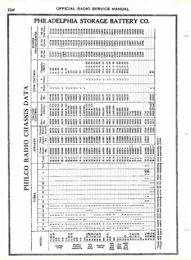
PHIL
CO
RA
DIO
CH
ASS
IS D
AT
A
MO
DE
L27
TU
BE
SSP
EA
KE
RV
LU
ME
CO
NT
RO
LT
ON
E C
ON
TR
OL
POW
ER
TR
AN
SFO
RM
ER
2435
4745
8014
1732
3330
23
71A
.
Typ
eC
one
Ass
em-
bly
Fiel
dA
ssem
-bl
y
Out
put
Tra
ns-
form
er
Part
No.
Res
ista
nce
(Ohm
s)Pa
rtN
o.2
Poin
t4
Poin
tC
apac
ity(M
fd.)
50-6
0C
ycle
s25
-40
Cyc
les
50-6
023
0 V
olts
78 B
.G.
14
...1
...1
...K
-302
996
0298
726
7350
3950
00 8
s 21
003
140
V2-
.01
5117
5118
5119
7411
-4.B
.1
4...
1..
1..
,.
K-3
0299
602
987
2673
5039
5000
8s
210
0314
0V
2-.0
151
1751
1851
1927
01
4...
1...
1.
.K
-302
996
0298
726
7350
3950
00 e
s 21
003
140
V2-
.01
5117
5118
5119
il °I1
X
370
14
...1
...1
......
....
K-3
0299
602
987
2673
5056
5000
es
210
0316
8V
2-.0
1
2-.0
1
5117
1511
751
1815
118
5119
(511
941
02
5...
1...
1...
....
K-4
0299
602
987
2673
5039
5000
es
210
0314
0V
159p
615
923
1592
451
01
4.
.1
...1
......
.K
-302
996
0298
726
7350
3950
00 8
s 21
003
140
V2-
.01
5117
5118
5119
70 B
.G.
11
31
...1
......
..K
-302
996
0298
726
7360
151,
000,
000
0363
7V
0151
1751
1851
19
u70
H.B
.1
13
1.
1...
......
..K
-302
996
0298
726
7360
151,
000,
000
0363
7V
0151
1751
1851
19
'El
210
11
31
...1
......
..K
-302
996
0298
726
7360
151,
000,
000
0363
7V
0151
1751
1851
19
12 t
o>u
e
310
4.70
1 2
1 2
3 3
1 1
...
...
1 1
... ..... ...
....
K-3
K-4
0299
6
0299
6
0298
7
0298
7
2673
2673
6307
6015
1,00
0,00
0
1,00
0,00
0
0465
2
0363
7V V
01 01
5117
f 51
1715
906
5118
1511
815
923
5119
f 51
1915
924
510
11
31
..
1...
....
....
K-3
0299
602
987
2673
6015
1,00
0,00
003
637
V01
5117
5118
5119
90 B
.G.
24
......
21
..
....
......
K-2
0299
602
987
2766
5039
5000
es
210
0313
7V
.015
,2-.
0149
3849
3949
40
2,,,,
-9D
L.F
r.90
H.S
.2 2
4 4... ...
... ..
2 21 1
... ......
......
......
....
....
H-2
H-2
0287
402
874
0298
802
988
2766
2766
5039
5039
5000
lis
210
5000
es
210
0313
703
137
V V.6
15, 2
-.01
.015,2-.01
4938
4938
4939
4939
4940
4940
9D B
.G.
43
...1
...1
....
K-3
0299
602
987
2673
5724
500,
000
0313
7V
.015
, 2-.
0153
6253
6353
64
.g,"
99 L
.B.
43
...1
..1
..H
-302
874
0298
826
7357
2450
0,00
003
137
V.0
15, 2
-.01
5362
5363
5364
i399
H.B
.4
3.-
..1
..1
......
......
H-3
0287
402
988
2673
5724
500,
000
0313
7V
.015
, 2-.
0153
6253
6353
6401 a.
490
....
....
K-4
0299
602
987
2673
5724
500,
000
0313
7V
.015
, 2-.
0115
362
1590
615
363
1592
315
364
1592
490
B.G
.3
12
2...
1...
.....
......
....
K-5
0299
602
987
2635
6015
1,000,000.
0313
7.
V.0
15, 2
-.01
6072
6073
6074
11 e
la,
9DX
H-6
K-8
0287
4
0299
6
0298
8
0298
7
2635
2635
6015
6015
1,00
0,00
0
1,00
0,00
0
0313
7
0313
7V V
.015
, 2-.
012-
.01
6072
1607
260
7316
073
6074
1607
449
0.0
15,
1590
615
923
1592
4lg
.11
2H
-202
874
0298
827
6640
9350
0,00
003
137
V.0
15, 2
-.01
4446
4447
4595
XIV
;21
24
4...
...2
1...
....
H-2
0287
402
988
2766
4093
500,
000
0313
7V
.015
,2-.
0144
4644
4745
95
,11
2...
H-6
0287
402
988
2635
4093
500,
000,
0313
7V
.015
, 2-.
0155
9455
9555
96
22 e
ia
112X
212
44
...2
...1
.....
......
......
. ..H
-6H
-602
874
0287
402
988
0298
826
3526
3540
9340
9350
0,00
050
0,00
003
137
0313
7.V
v'
.015
, 2-.
01.0
15, 2
-.01
5594
5594
5595
5595
5596
5596
5D B
.G.
...3
...1
...1
...
......
.P-
202
861'
0294
226
6052
3217
5052
6652
6752
68...
.S-
202
887*
*02
942
2660
5232
1750
5266
5267
5268
P-2
0286
102
942
2660
5839
5000
5266
5267
5268
...
S-2
0288
702
942
2660
5839
5000
5266
5267
5268
551
..
21
1...
1..
,...
....
....
P-2
0286
1*02
942
2660
5839
5000
5266
5267
5268
4.
..
..
..
.57
8557
8657
87...
31
......
...1
1 (E
)2
N-2
0299
602
924
2766
4141
1750
...3
1.
..
..
.1
1 (E
)2
N-2
0299
602
924
2766
4141
1750
3S B
.G.
....
.R
-202
887*
*26
4653
1750
00 (
Dua
l)03
637
V01
35 H
.B.
.....
R-2
0288
7026
4653
1750
00 (
Dua
l)_
0363
7V
01
'Use
d w
ith s
pace
r w
ashe
r 33
16 a
nd m
ount
ing
scre
w W
-161
whe
n re
plac
ing
cone
ass
embl
y 02
970.
**U
sed
with
spa
cer
was
her
2616
and
mou
ntin
g sc
rew
W-1
61 w
hen
repl
acin
g co
ne a
ssem
bly
0294
9.
1.e.
r1%
.1
On -n

OFFICIAL RADIO SERVICE MANUAL326(.
PHILADELPHIA STORAGE BATTERY CO.Checking I. F. Oscillator Calibration
Any oscillator which is not crystal controlled particularly those which are battery oper-ated and portable, should be checked from time to time for correct frequency calibration. Thecalibration can be appreciably affected by rough handling of the oscillator while it is beingmoved about, and by the condition of the tubes and batteries. If an oscillator is in constantdaily use, it should be checked two or three times a week and any necessary adjustment madeto correct errors in calibration.
One of the most accurate and convenient methods of making this check is through the useof the signals from reliable broadcasting stations. Most of the better class stations have accu-rate crystal controlled frequency regulation which assures broadcasting on the assigned fre-quency. Intermediate frequency oscillators can be checked with the aid of broadcast signalsin the following manner:
175 KC Intermediate Frequency Oscillator Check-Place radio set in operation, andtune it accurately to a station broadcasting on any of the following frequencies: 700, 1050, or1400 KC. When a station is heard at any one of these three points, disconnect the antennaand substitute a connection to the output of the oscillator. Place the oscillator in operation at175 KC. If the oscillator is calibrated correctly, its signal should be heard on the receiverwithout changing the tuning of the broadcast receiver in any way. If it is necessary to re -tunethe set before the oscillator signal can be heard at maximum volume for the particular settingof the attenuator and the radio set volume control, the oscillator is off calibration. Its compen-sating condenser should be re -adjusted until the signal is heard at exactly 700, 1050, and 1400KC. (These frequencies are the fourth, sixth, and eighth harmonics of 175 KC.) In the PhilcoOscillator Model 095, this compensating condenser is the one nearer the 175 KC switchposition.
260 KC Intermediate Frequency Oscillator Check-Proceed in the same manner a,for the 175 KC check described above, but tune the broadcast receiver to a signal at 780, 1040,or 1300 KC. Remove the antenna and substitute the connection from the oscillator, thelatter being in operation at 260 KC. Check in the same manner as for 1'75 KC, making anynecessary adjustments of the 260 KC compensating condenser so as to make the oscillatorsignal heard at 780, 1040, or 1300 KC. (Third, fourth, and fifth harmonics, respectively of260 KC). In the Philco 095 oscillator, this compensating condenser is nearer the 260 KCswitch position.
POWER CONSUMPTION OF PHILCO MODELS
A number of requests have been received for information on thepower consumption of various Philco Receivers. The table below lists thedifferent instruments with the power consumption in watts of each.
Model Watts
511 75 A . C .
65 95 11
86 9087 9576 9577 9595 10596 105 "
296 14520 75 "
220 100 "
111 105
Model Watts
211 13570 80 11
The power consump- 90 95
tion of the 25 cycle 112 105
models is the sane 212 135as that of the 60 270 100 "
cycle models. Instru- 40 210 D.C.ments rated at 230volts consume thesame power as thoserated at 110 volts.
41
41-E210 D.C.420 "
42 21042-E 420 11
40 42 "

326HOFFICIAL RADIO SERVICE MANUAL
EARTHq N D
RAN1PLtie L,
RCA -VICTOR, INC.
es,227
Cat
Rs T cis.111,
3
C,6Mit
C
REcT280
CI7 oo.o. C115
L11
QCOCT
o Hea'TRS=Rt 0 RotCu
S. DIAL LIGHT
1112 =Dom
R 1000 OHMSR. 4350 OHMS V.C.R. ISO OHMSR !Goo° owlsR 5 10000 OHMSR 6 40000 OHMSR 7 50000 OHMSR 3 30000 OHMSR3I.R.,. 501000 OHMSR l00000 OHMS
0000
OHMS011
MS
VICTOR CONSOLE R-6Figure 1-Schematic Diagram for 7 -tube Receiver
ft°,41rm1(
LIA01MIN PM
C 18-32 5 MMFDC 18-325 MMFDC 3 18-325 MMFD
4-30 MMFDC 0 4-5o MMFDC 6 4 -So MMFDC 7 15..75 MMFOC g 140 -etc MaoC 1400 MMFDC,. .01 MFDC,, 2400 KW*C,2 .5 MFD
. 1 MFDC .02.5 MFDcu .1 MDC 8. MFDC17 8. MFDC,, 4. MFDC,3 .5 MADCa. .05 RFDC,. 77o riffDCat 745 MVO
co44718C710181OR ItLEUSTOR 804120
-5' -
Figure T.-Wiring Diagram tot 7 -tube Receiver
OFFICIAL RADIO SERVICE MANUAL3261
RCA -VICTOR, INC.SERVICE NOTES
for
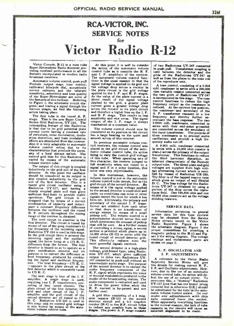
Victor Radio R-12Victor Console, R-12 is a nine tube
Super -Heterodyne Radio Receiver pro-viding excellent performance in all thefeatures incorporated in modern radiobroadcast receivers.
Automatic volume control, push-pullPentode output stage, tone control,calibrated kilocycle dial, acousticallycorrect cabinets and the inherentsensitivity, selectivity and tone qualityof the Super -Heterodyne are some ofthe features of this receiver. Referringto Figure I, the schematic circuit dia-gram, and tracing a signal through thevarious stages, we find the followingaction taking place.
The first tube is the tuned R. F.stage. This is the new Super ControlScreen Grid Radiotron, UY-235. Theoutstanding feature of this Radiotronis that due to its grid potential platecurrent curve having a constant rateof curvature, cross modulation, modu-ation distortion, and hum modulationeffects are eliminated from the receiver.Also it is very adaptable to automaticvolume control action due to itscharacteristics that preclude the neces-sity of a local distant sw:tch. Thecontrol grid bias for this Radiotron isvaried by means of the automaticvolume control tube.
The output of this circuit is coupledinductively to the grid coil of the firstdetector. At this point the oscillatorshould be considered as its output isalso coupled inductively to the gridcoil of the first detector. This is atuned grid circuit oscillator using aRadiotron UY-227, and having aclosely coupled plate coil that givessufficient feed -back to provide stableoperation. The grid circuit is sodesigned that by means of a correctcombination of capacity and induct-ance a constant frequency differencebetween the oscillator and the tunedR. F. circuits throughout the tuningrange of the receiver is obtained.
The next circuit to examine is thefirst detector. The circuit is tuned bymeans of one of the gang condensers tothe frequency of the incoming signal.Radiotron UY-224 is used in this stage.In the grid circuit there is present theincoming signal and the oscillatorsignal, the latter being at a 175 K. C.difference from the former. The firstdetector is biased so as to operate as aplate rectification detector and itspurpose is to extract the difference orbeat frequency, produced by combin-ing the signal and oscillator frequen-cies. The beat frequency ---175 K. C.- appears in the plate circuit of thefirst detector which is accurately tunedto 175 K. C.
The next stage is that of the I. F.amplifier. A single stage is used,requiring two I. F. transformers, con-sisting of four tuned circuits. Theplate circuit of the first detector, thegrid and plate circuit of the I. F.amplifier and the grid circuit of thesecond detector are all tuned to 175K. C. Radiotron UY-235 is used inthis stage and its control grid voltageis also varied by means of the auto-matic volume control tube.
At this point it is well to considerthe action of the automatic volumecontrol tube as it controls the R. F.and I. F. amplifiers of the receiver.The automatic volume control func-tions in the usual manner in that thesignal voltage is applied to its grid andthe voltage drop across a resistor inthe plate circuit is the grid voltageapplied to the I. F. and R. F. stages.As the value of the plate current is adirect result of the signal voltageapplied to the grid, a greater platecurrent gives a greater voltage dropacross the resistor in its plate circuitand therefore a higher bias on the I. F.and R. F. stage. This results in lesssensitivity and vice versa. The signaloutput of the I. F. stage is alwaysmaintained at a constant value.
The volume control should now beconsidered as its position in the circuithas a large bearing on the quiet andsmooth action of this receiver.
In previous automatic volume con-trol receivers, the volume control wasplaced in the grid circuit of the auto-matic volume control tube, its actionbeing to vary the control grid voltageof this tube. When operating sets ofthis character, the receiver jumped tofull sensitivity when not tuned to asignal and if in a noisy location, thisnoise was very objectionable.
In this instrument, however, thevolume control is not in the automaticvolume control tube circuit, but in thegrid circuit of the second detector. Bymeans of it the signal voltage appliedto the second detector is controlled andunder no conditions can noise or othersignals exceed the level for which it hasbeen set. Electrically, the primary andsecondary of the second I. F. trans-former are shielded from each otherso that there is no transference ofenergy except by means of a smallpickup coil. The volume control is apotentiometer shunted across this coilwhich determines the amount of pickupthat will be used. As a further meansof controlling a strong signal, a secondsection is provided which places up to10,000 ohms (R-21) in series with thetuned circuit of second detector grid.This effectively reduces even themost powerful signals received.
The second detector is a high -platevoltage, grid -biased type, using Radio-tron UY-227, which gives sufficientoutput to drive two Radiotrons UY-247 connected in push-pull without anintermediate audio stage. The purposeof the second detector is to extract theaudio frequency component of theR. F. signal which represents the voiceor musical modulations produced in thestudio of the broadcasting station. Theaudio component is extracted and usedto drive the power tubes while theR. F. current is by-passed and notfurther used.
A grid filter consisting of a 1 meg-ohm resistor (R-13) in the seconddetector circuit and a 0.5 megohmresistor (R-4) in the R.F. circuit helpsto reduce any possible hum in thesestages. The power A. F. stage consists
of two Radiotrons UY-247 connectedin push-pull. Transformer coupling isused between the detector and thegrids of the Radiotrons UY-247 aswell as from the plates to the cone coilof the reproducer unit.
A tone control, consisting of a 0.008mfd. condenser in series with a 200,000ohm variable resistor connected acrossthe two grids of Radiotrons UY-247is incorporated in this stage. The tonecontrol functions to reduce the highfrequency output as the resistance isreduced. At the extreme low position,the condenser and secondary of theA. F. transformer resonate at a lowfrequency and thereby further ac-centuate the bass response. The two0.0004 mfd. condensers, connected inseries with their mid -point groundedare connected across the secondary ofthe input transformer. The purpose ofthese condensers is to prevent audiooscillations and provide a high fre-quency audio cut-off.
A 0.005 mfd. condenser connectedin series with a 10,000 ohm resistor isplacid across the primary of the outputtransformer. This functions to reducethe third harmonic distortion, aninherent characteristic of the Pentodeoutput tube. The direct plate and gridvoltages are supplied from high volt-age alternating current which is recti-fied by means of Radiotron UX-280.The filter is of the tapped reactor typewhich gives an output of well filteredD. C. The bias voltage for the Radio-trons UY-247 is obtained by using .aportion of the drop across the repro-ducer field. One 190,000 ohm and one40,000 ohm resistors act as the voltagedividing resistors.
SERVICE DATAInformation pertaining to general
service data for this type receivermay be obtained from the ServiceNotes already issued on the VictorRadio Superette. Figure 1 showsthe schematic diagram, Figure 2 theproper connections for attaching amagnetic pickup to the R-12 and Fig-ure 3 the wiring diagram. The voltagereadings and replacement parts areshown on page 3.
R. F. OSCILLATOR ANDI. F. ADJUSTMENTS
A reference to the Victor RadioSuperette Service Notes will givethe details for making correct R. F.,I. F. and Oscillator adjustments. How-ever, due to the use of an automaticvolume control tube, its action will de-feat the use of an output meter. Toovercome this, a "dummy" RadiotronUY-227 (one that has one heater prongremoved but is otherwise O.K.) shouldbe substituted for the tube in the auto-matic volume control socket. Do notmake any adjustments with thistube removed from the socket.While apparently everything functionsin the normal manner, the lack of tubecapacity in the circuits will cause anincorrect alignment to be made.

tl
4
11-9
, 3,0
00 O
HM
SI1
-D
1, 1
0.00
0 O
HM
S
VO
LUM
EC
ON
TR
OL%
GN
D T
OF
AN
IL
GAu
GA
EL
7 " °
C-9
"15
-75
MW
D
000
t`B
LAC
K W
ITH
OC
LLO
NIP
AC
IK:
- E
D A
ND
TIL
ED
ar
EH
_
BR
O R
-.
VE
LLO
w
RE
D A
ND
SLA
CK
C-4
C -
I
c -S
C-2
^B
LAC
K
b-Y
ELL
O
- A
WE
P-9
5
E L
Ow
RE
D*-
-O
UT
PU
TT
RA
NS
FO
RM
ER
TO
TA
L
MA
CK
,7H
OLL
OW
1
--R
ED
-
AG
WR
ITRN
0.3.
BLA
CK
TO
AN
T. T
O G
MLO
UD
SP
EA
KE
R
+T
AW
*C
ON
NE
CT
ION
S
RN
AC
K
V[L
LDW
-.G
RE
EN
!:r71
.-'
E.-
41
5000
00A
LAC
KA
lull
6ltE
EN
DA
D R
EO_e
AR
OM
AH
IT(
MA
RO
ON
YE
LLO
W
BROWN
ED
WIT
H R
ED
TR
AC
ER
-
C-21
4C
-I9
(.9
MM
ED
AW
N c
ossa
llite
ll
SP
Ow
m_
BR
OW
N-
300.
.T
OT
AL,
w
o-Y
ELL
OW
SLA
CJL
YE
LLO
W
RE
D
MIR
E
RIO
T
SLU
ES
LUE
MM
FO
.G
RE
EN
YE
LLO
W
kilt
AN
DY
ELL
OW
TO
NE
CO
NT
RO
LA
ND
OP
ER
AT
ING
SW
ITC
H
-40
,00,
R-1
2
30.0
00.
R-1
150"
R-
I50
0.00
0.
1 M
EG
'
C-3
000
8 M
E D
.
CY
H4D
C -
3I.0
05 m
Fo. ta 0.
11 ME
G1:
1 1400
0IN
TE
RN
AL
CO
NN
EC
TIO
NS
OF
RE
SIS
TO
R B
OA
RD
PE
E
-BLU
R W
ITH
RE
D T
RA
CE
R
INT
ER
NA
LO
F P
OW
ER
IAD
; G.
Wir
ing
Dia
gram
of
Mod
el R
-12.
GR
EE
N
R -
ISK
owa
R-1
7-1
90,0
00"
R -
I640
000"
BLA
CK
- SLU
ER
IME
RS
LUE
-AN
D-Y
ELL
OW
- rA
t
BLU
EU
GH
TB
RO
WN
MG
MB
RO
WN
-AN
D-S
LAC
K-Y
OLT
AG
E2.
30,,
BR
OW
NG
RE
EN
HE
AT
ER
GR
EE
N
VIE
LLO
WU
X-2
10F
ILA
ME
NT
YE
LLO
W
CO
NN
EC
TIO
NS
TR
AN
SF
OR
ME
R
PR
IMA
RY
2300
-,
BLU
E
SE
CO
ND
AR
Y77
00"
TO
TA
L
-BLU
E-A
ND
-YE
LLO
W--
YE
LLO
WR
UE
INT
ER
NA
L C
ON
NE
CT
ION
S O
FIN
TE
RS
TA
GE
TR
AN
SF
OR
ME
R
C-2
71
C -
r5;
256
igp.
Itit
aM
OO
WH
O. R
AW
MF
O.
MF
O.
3 L
II
g*
,t3/
..
a.g
C-4
15 C
-I1
40.
5C
6.11
Of
Dl7
'C-2
0I i
ll M
ID. M
ED
. MO
O. R
OD
MID
. 2 m
il).
AD
.
INT
ER
NA
L C
ON
NE
CT
ION
SO
F C
AP
AC
ITO
R P
AC
K
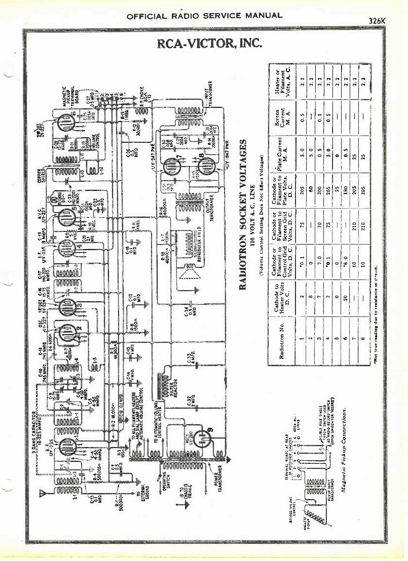
r.Il
i I V
I I,
.1
guirI
S T
O
CH
AS
SIS
FR
AM
E
RE
CO
RD
VO
LUM
EC
ON
1RC
L
MA
GN
ET
ICP
ICK
UP
5lia
1:1
01
MF
D.
R-1
--50
0,00
0
1 -G
AN
G C
AP
AC
ITO
Ros
s.1.
1.6.
1.n.
r=
aiw
aras
i firr
ILM
".=
111
1.n.
11.
F -
I.0
C.I0
Cli
01II
745
MM
FD
.74
5 M
MF
D,
1
11
UY
-23
5
c -
L-2
TO
EX
TE
RN
AL
GR
OU
ND
R. F
.
"C-4
R-4
4-50
500.
000"
MM
FD
.
C-g
g
0:2:
0M
MF
D.
r=s
ii2
11a
L-4
4- cl
.3 ,s
cs)
L-6
1
MF
D.
Tar
C-5
1111
,
tuft
Mr2
1SO
AC
-8 D
J M
FD
.
C-7
--R
-2 1
8.00
0n
TO
ALL
FIL
AM
EN
TS
HE
AT
ER
S
A 1
4110
1111
NeV
rAC
I0IT
IT12
01
ti
R -
S44
300A
±5
CM
FD
.'1
MF
D.
C
CO
NT
RO
L H
EA
TE
RT
O A
UT
OM
AT
IC V
OLU
ME
SW
ITC
H1L
(N?
OP
ER
AT
ING
0000
0F
ILT
ER
RE
AC
TO
R
TE
RM
INA
L B
OA
RD
AT
RE
AR
OF
RE
C IV
ER
CH
AS
SIS
It
34
56
OP
EN
ALL
QLI
NK
S
PIC
KU
P IN
PU
TT
RA
NS
FO
RM
ER
C-3
2
n ne
2 M
FD
.
,DO
UB
LE P
OLE
SIN
GLE
TH
RO
W S
WIT
CH
US
ED
AS
IIAD
IOR
EC
OR
D. S
WIT
CH
(OP
EN
SW
ITC
H F
OR
'Rec
ur)
Mag
netic
Pic
kup
Con
nect
ions
.
4C M
FD
.
1E P
ET
. C -
I6U
T -
224
15-7
5,M
MF
D.
R-8
1500
n
7--
IC
-12
0.1
MF
D.
C-3
4
M0.
FD
5
n
C-1
7I.F
.C
-19
140-
220
UY
-235
, .9
MM
FD
.
S
4
0.1C-I
8
MF
D...
R -
IIM
EG
.
A.V
.C.
UT
-22
7C
OP
PE
RS
HIE
LD
R-9 5
ME
620
0.1
MO
D
It -1
8R
-17
40,0
00e%
1900
00*
"M.
1111
1111
2WE
RR
IER
EP
RO
DU
CE
R F
IELD
L-9
C-2
3--
140.
2_20
MM
0.
2100
24M
FD C-2
.52
0 MF
D.
R-1
640
000f
t.
0 OU
TP
UT
TR
AN
SF
OR
ME
R
6C
S
.002
4M
FD
.
MA
GN
ET
ICP
ICK
UP
'TE
RM
INA
L
BO
AR
D
C-2
7I
0.5
MO
D.)
4
C-2
6---
---
)V
MF
D.
3030
012n
UY
-247
PW
R
..4.1
Y -
147
PW
R.
RA
DIO
TR
ON
SO
CK
ET
VO
LT
AG
ES
110
VO
LT
A. C
. LIN
E(V
olum
e C
ontr
ol S
ettin
g D
oes
Not
Eff
ect V
olta
ges)
R-1
1M
2 3
A. F
.C
HO
KE i
1/4:
13
- -I
NP
UT
TR
AN
SF
OR
ME
R
Rad
iotr
on N
o.C
atho
de to
Hea
ter
Vol
tsD
. C.
Cat
hode
or
Fila
men
t to
Con
trol
Gri
dV
olts
, D. C
.
Cat
hode
or
Fila
men
t to
Scre
en G
rid
Vol
ts, D
. C.
Cat
hode
or
Fila
men
t to
Plat
e V
olts
,D
. C.
Plat
e C
urre
ntM
. A.
Scre
enC
urre
ntM
. A.
Hea
ter
orFi
lam
ent
Vol
ts, A
.C
.
2*0
.175
205
5.0
0.5
2.2
2.8
0-
605.
0-
2.2
37
7.0
7020
00.
50.
12.
24
2*0
.175
205
5.0
0.5
2.2
50
0-
250
-2.
26
20*8
.0-
180
0.5
-2.
27
- -10
210
205
25-
2.2
810
210
205
25-
2.2
1
*Not
true
rea
ding
due
to r
esis
tanc
e in
ere
isit.

326LOFFICIAL RADIO SERVICE MANUAL
RCA -VICTOR, INC.
SUPPLEMENT
to
VICTOR RADIO R-12 SERVICE NOTES
Late production of the Victor Radio R-12 has a slight changein the wiring, two changes in capacitor values and the addition of a 0.5megohm resistor (R-20). Capacitor C-7 has been changed from 0.5 mfd.to 0.1 mfd. and C-13 from 0.1 mfd. to 0.05 mfd. Resistor R-20 has beenadded.
Figure 1 shows the revised schematic diagram and Figure 2 thewiring diagram.
The replacement parts listed and supplied are entirely interchange-able with either the old or new models. In the case of the older models,however, the additional black lead supplied in the new capacitor packshould be joined to the old black ground lead. All other capacitor leadsare exactly the same and are soldered to the same points.
MOD
2.4
L57001151TO lr
(muse
ONEWINGSINiTCN
IS TOCNA5540FRAME
FRATSVMER
V
S GANG CAPACITOR
F.of -235
2-2 18.000,"
C -64 SOMIA,
4.03 OA 10
TO ALL MUM (111-5, WATERSMID DIAL LAMP I0,CAPT
ALITOMAT/C VOLUME CONTROL
C-10 C-11 OSC I d247. C -I6 C47 I. F. C-111 AV C.74S 551015 ,744 iMM
PA0
A11-2 7 UT -224 IS -MD
75 140-220 v -2.35, .9 Will 4,1J-227A
ACCOA
(5
2-74X00.
L-5
0-544300N
C-14 C-15INFO INFO.
TO AUTOMATIC VOL hitCORM% NEATER SO
0.4RFD.
C.3403:MAO
ZR4IOINK
12.58 R 47.55000!,
REPRODUCER FOLD
WPM5MLD
Figure I-Revised Schematic diagram of late production R-12
v-247 MC

VO
LUM
EC
ON
TR
OL.
..
FRA
ME
(
Ill1
CIK
WIT
H11
.11C
WIT
IIW
CU
I:
a G
c, " 2
nuow
DE
UR
MD
AN
D M
EO
W
liS
T L
i
1
TO
AN
T. T
O E
ND
.
4.4.
OIE
EN
C10
_,=
=t
,
C1
(A*
A-4
1
41,1
E00
.000
A
-4-
IS-7
S
MFG
Ma
Et)
SLU
E
GLE
N A
ND
RE
D -
0
WH
ITE
mA
RO
O
YE
LLO
W
GR
OW
N
ED
SLA
CK
RE
D" O
UT
PU
TIII
TR
AN
SF
OR
ME
RD
IAO
'-610
.H.
TO
TA
LR
ED
+
volyo WAWA
MO
WN
MI R
ED
TE
LC2:
0-
fC-1
99
MIA
MI
Slo
WN
-
ME
LON
I (-D
UX
YE
LLO
W
.SR
OW
NG
RO
wN
-30
0.-
TO
TA
L1
Si03
4Li
tiehl
ad
YE
LLO
W -
MD
£50
MA
CK
9
TIM
-G
uth
61?
C-4
- S
LUE E
t*-N
'"""j
'ME
D. M
tiL
NE
DR
ID
ON
O. T
O
FR
AM
E,;_
.
SU
CK
litu.
14fit
o,
YE
LLO
W-'
SLU
R SLU
E
MA
UL
DR
EE
S
YE
LLO
W
SLU
R S
AD
YE
LLO
W
5-1
IM G
Figu
re 2
-Wir
ing
diag
ram
of
late
pro
duct
ion
R-1
2
CIr
icia
OL
OR
AN
AN
GS
WIT
CH
5-IS
10,0
00"
5-17
5-17
1,0,
000^
11-1
_40
,0D
00A
INT
IAN
AL
CO
NN
EC
TIO
NS
OF
RE
SIST
OR
SO
AR
S
RE
D
-SL
AC
KM
TN
19(
0 T
RA
CE
R
LAC
K
SLU
EH
ann
AN
DU
E-A
ND
-YE
LLO
W--
DIA
L
ovni
4joe
llLU
Row
olkA
cEN
--__
K-v
tr;H
TE
SR
OW
N-.
---
GR
EE
N
GR
EE
NY
ELL
OW
OX
-2S
0FI
LA
ME
NT
A.V
.C.
NE
AT
ER
YE
LL
OW
INT
ER
NA
L C
ON
NE
CT
ION
SO
F PO
WE
R T
RA
NSF
OR
ME
R
-GR
EE
K PRIM
AR
Y23
00"
SLU
E-
SEC
ON
DA
RY
7700
,MT
AL
-AN
D-W
ELL
OW
--
TU
LO
WSL
UE
INT
ER
NA
L C
ON
NE
CT
ION
S O
FM
UL
TIA
GE
TR
AN
SFO
RM
ER
cp53
1a
ligI
RA
F)
DA
REma.
wpm
c
Cil4
S-1
1d
CM
FO
.U
HL
IAE
Aa
INT
ER
NA
L C
ON
NE
CT
ION
SO
F C
APA
CIT
OR
PA
CK

OFFICIAL RADIO SERVICE MANUAL326N
RCA -VICTOR, INC.
SERVICE NOTESfor
VICTOR RADIO R-20 and R-21The Victor Radio R-20 and R-21
are ten tube screen grid automaticvolume control Super -Heterodyne radioreceivers. With the exception of theAudio Transformer, Speaker and Cabi-net both models are identical.
Features of these Models are. SuperControl Screen Grid Radiotrons in theR. F. and I. F. stages, automaticvolume control so arranged in thecircuit to reduce noise between chan-nels, push pull Pentode output stage,accurately calibrated dial readingdirectly in kilocycles, totally shieldedchassis and sensitivity, setactiVity andfidelity superior to any previousVictor receiver.
Referring to Figure 1 and tracing asignal through the various stages, wefind the following action taking place.
The signal voltage, indsuced into theantenna system, is coupled by meansof the antenna coil to the tuned circuitof the "link circent." The link circuittunes exactly with the tuned R. F. andfirst detector circuits. There is nogain in the circuit, it being merely aselection circuit.
A tuned R. F. stage follows whichuses Radiotron UY-235. The controlgrid bias for this tube is a function ofthe automatic volume control tube. Theoutput is coupled inductively to thefirst detector grid circuit together withthe output from the oscillator.
The first detector is tuned by oneunit of the gang condenser. In itsgrid circuit, there is present the incoming signal and the oscillator signal, thelatter being at a 175 K. C. higherthan the former. The tube is biasedso as to operate as a plate rectificationdetector and its purpose is to extractthe difference or beat frequency, produced by combining the signal andoscillator frequencies. The beat fre-quency -175 K. C. - appears in theplate circuit of the first detector whichis accurately tuned to 175 K. C. Thetube used as a first detector is Radio-tron UY-224.
The next circuit is that of the firstI. F. stage. It is a high gain Amplifierhaving both its grid and plate circuitstuned to 175 K. C. Its grid voltage iscontrolled by the automatic volumecontrol tube.
At this point the automatic volumecontrol tube should be considered asits grid is controlled by the output fromthe first I. F. Stage.
The automatic volume control tubez-nunncr in that
the signal voltage is applied to its gridand the voltage drop across a resistor
in its plate circuit is the grid voltageapplied to the R. F. and first I. F.amplifier. As the value of the platecurrent is a direct result of the signalvoltage applied to the grid, a greaterplate current gives a greater voltagedrop across the resistor in its platecircuit and therefore a higher bias onthe R. F. and I. F. stage. This resultsin less sensitivity and vice versa. Thesignal output of the first I. F. stage isalways maintained at a constant value.
The volume control should now beconsidered as its position in the circuithas a large bearing on the quiet andsmooth action of the receiver.
In previous automatic volume con-trol receivers, the volume control wasplaced in the grid circuit of the auto-matic volume control tube, its actionbeing to vary the control grid voltageof this tube. When operating sets ofthis character, the receiver jumped tofull sensitivity when not tuned to asignal and if in a noisy location, thisnoise was very objectionable.
In this instrument, however, thevolume control is not in the automaticvolume control tube circuit, but in thegrid circuit of the second I. F. Amplifier.By means of it the signal voltageapplied to the second I. F. amplifier iscontrolled and under no conditions cannoise or other signals exceed the levelfor which it has been set. Electrically,the primary and secondary of thesecond I. F. transformer are placed sothat there is no transference of energyexcept by means of a small pickup coil.The volume control is a potentiometershunted across this coil which deter-mines the amount of pickup that willbe used.
The second detector is a high -platevoltage, grid -biased type, using Radio-tron UY-227, which gives sufficient out-put to drive two Radiotrons UY-247connected in push-pull without anintermediate audio stage. The purposeof the second detector is to extract theaudio frequency component of theR. F. signal which represents the voiceor musical modulations produced inthe studio of the broadcasting station.The audio component is extracted andused to drive the power tubes whilethe R. F. current is by-passed and notfurther used.
A grid filter consisting of a 1 megohmresistor in the second detector circuithelps to reduce any possible hum inthese stages. The power A. F. Stageconsists of two Radiotrons UY-247connected in push-pull. Transformercoupling is used between the detectoranti tin: grids of tlic Radiutran UY-247as well as from the plates to the conecoil of the reproducer unit.
A tone control, consisting of aninductor .01 mfd. Capacitor and a 0.5meg. variable resistor is in the platecircuit of the second detector. Thetone control functions to reduce thehigh frequency output as the resistanceis reduced, without accentuating thebass response. The two 0.0004 mfd.condensers, connected in series withtheir mid -point grounded are connectedacross the secondary of the imput trans-former. The purpose of these con-densers is to prevent audio oscillationsand provide a high frequency audiocut-off.
A 0.005 mfd. condenser connected inseries with an 18,000 ohm resistor isplaced across the primary of the outputtransformer. This functions to reducethe third harmonic distortion aninherent characteristic of the Pentodeoutput tube. The direct plate andgrid voltages are supplied from highvoltage alternating current which isrectified by means of Radiotron UX-280. The filter is of the tapped reactortype which giilles an output of wellfiltered D. C. The bias voltage ofRadiotrons UY-247 is obtained byusing a portion of the drop across thereproducer field. One 100,000 and20,000 ohm resistors act as the voltagedividing resistors.
SERVICE DATA
Information pertaining to R. F.,oscillator and I. F. adjustmentstogether with general service data forthis type receiver may be obtainedfrom the Service Notes already issued.Figure 1 shows the schematic diagram.
R. F. OSCILLATOR ANDI. F. ADJUSTMENTS
A reference to the Victor RadioSuperette Service Notes will give thedetails for making correct R. F., I. F.and Oscillator adjustments. However,due to the use of an automatic volumecontrol tube, its action will defeat theuse of an output meter. To overcomethis, a "dummy" Radiotron UY-227(one that has one heater prong removedbut is otherwise 0. K.) should be sub-stituted for the tube in the automaticvolume control socket. Do not makeany adjustments with this tube re-moved from the socket. While appa-rently everything functions in thenormal manner, the lack of tubecapacity in the circuits will cause anincorrect alignment to be made.
In the Model R-20 and R-21 theI. F. transformers are adjusted formaximum output and no attempt atband pass tuning should be made whenthese adjustments are made.
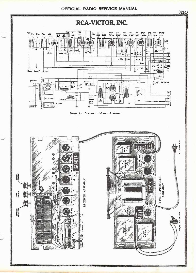
aA
W /
/ MI \
WI I
WI X
i/ A
%II\
IMIM
MIIM
IMM
IMM
/
N.
ST
AT
ION
SE
LEC
TO
RT
ON
IM
AW
CO
NT
RO
LrCONTROL
7-
--
t
-.".
1119
1
II!- .;111
1
Itil II'
1
:\
II
_
I i It,
- 14i.
11I
1
I
11
401.
21=
Aci
s- ,D
1141
w,
GR
UM
.
uryt
ime_
dAL
LAM
P S
OC
KE
Tk
,A
,nuo
wur
-235
CG
SLA
CK
II `
NO
ON
s- L
INK
F.
TO
OT
.T
O 6
110
CIR
CU
IT C
OIL
CO
IL
sk,,v
ot
PO
WE
RN
.k.
TR
AN
SF
OR
ME
R V
.,
"\'
FIL
TC
RR
EA
CT
OR
''
RE
CE
IVE
R A
SS
EM
BLY
'WsW
7 kw
\'\X
\,C
AP
AC
ITO
RP
AC
K T
4ttu
o w
ill\\
YlU
EW
111
1(1
c:x7
76 4
;To
2 3
2 2
UK
-23
0y
;I.ur
147
suY
-247
:
OP
ER
AT
ING
SW
ITC
H
S. P
. U.-
RE
PR
OD
UC
ER
AS
SE
MB
LY
A.C
. IN
PU
T P
LUG
IA 0 3 a A
It!
:100
31-3
i13
0ox
oxo
..11
--

326POFFICIAL RADIO SERVICE MANUAL
RCA -VICTOR, INC.
ti211. itik7/NCB -INTD. MIO 464
INTERNAL CONNECTIONS OFBYPASS CAPACITOR PACK
INTERNAL CONNECTIONS OFBY-PASS CAPACITOR PACK
IT- ivia7qA 11 i.
RESISTOR BOARD CONNECTIONS
Figure 2 -Receiver Assembly Wiring Diagram
RADIOTRON SOCKET VOLTAGESVOLTAGES ARE THE SAME AT EITHER POSITION OF THE VOLUME CONTROL
110 VOLT LINE
Radiotron No.Heater toCathode
Volts
Cathode orFilament orControl Grid
Volts
Cathode orFilament toScreen Grid
Volts
Cathode orFilament to
PlateVolts
PlateCurrentM. A.
HeaterVolts
1-R.F. 2.0 *0.2 58 210 3.0 2.5
2-0,e. 5.0 0 - 50 3.5 2.5
3 -1st Det. 4. 0 3.5 55 210 1. 1 2. 5
4 -1st I.F. 2. 0 *0. 2 58 210 3.0 2. 5
5-A.V.C. 0 0 - 30 0. 1 2. 5
6 -2nd I.F. 2. 0 3. 5 55 210 2. 0 2. 5
7 -2nd Det. 20.0 *8. 0 - 190 0. 5 2. 5
8-Pwr. - *10.0 230 215 25.0 2.5
9-Pwr. - *10.0 230 215 25.0 2.5
'These readings are not correct due to the resistance in the circuits.
Figaro 3-S.P. U. Raprotinaw Assimiiy Wiring
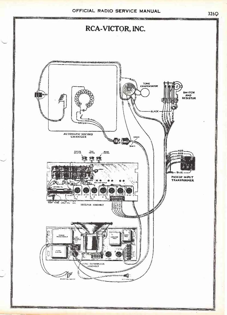
OFFICIAL RADIO SERVICE MANUAL326Q
SLACK
RCA -VICTOR, INC.
GREEN
AUTOMATIC RECORDCHANGER
STTION TONECONTROE
MORISELECTOR (MINK
7 7
oWn. re' W. c:41.7coit.. *01.
40 CotPlaco
ORSRRF.E, SIVITCO.
\:
4.) AA ®A0. LAW, SOCKET
w,flS U,42,2 3 4
RECEIVER ASSEMBLY
P U. -REPRODUCERASSEMBLY
TONECOMPENSATOR
SLAG
o
SWITCHAND
RESISTOR
REORED
BELLOW//;,,ELLO 50
t: 3 1
BLUE
PICKUP INPUTTRANSFORMER
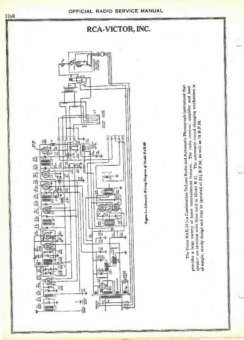
70
18-3
3080
02
Ert
IMP
E40
1810 O
PE
AT
M58
11 H
(IC
.4et
15./0
II 33
0km
Pl.
/4.0
0 54
910
0Y-2
33.
3.40
AIM
D.
1.p'
90f40 VIr
\ C
.7-3
3054
010
580
1.7
t34
ow.
"1§
.C2'
1
1.4
C-t
Olir
C-
18.3
305-
M15
010
.131
8
05(
(II
1511
ISC
16A
vC
729
1 f
5-22
C.2
3
EIN
.02
,01
070
.72
AW
E17
220
10.7
0(0
3110
1 24
005
491
120
210
10.7
0.
,,145
099
1203
1-2)
5, 'M
UC
CI
u122
7./4
10 D
00-2
35./0
110
1002
1
6.10E
ll 1
0.21
0119
019
01
C 3
3
I
C35
105
919.
100
I 71
7008
LII
020
8M 8, 1
27
1..1
737
00.
111E
2
114
QI 5
410%
2?II
C 2
8""
M"
I. 40
P.
(0 2
3
5-2
44.
IBM
41:4
4111
14
-0.-
---
4.-
0001
0P
RO
NE
50
68(1
3
Lzi
L AU
TO
MA
TIC
RE
CO
RD
(RA
NG
ER
Figu
r* 1
-Sch
emat
ic W
irin
g D
iagr
ans
ofM
odel
RA
E40
SLA
CK
The
Vic
tor
RA
E -
59 is
a C
ombi
natio
nD
eLux
e R
adio
and
Aut
omat
ic P
hono
grap
hin
stru
men
t tha
t
prov
ides
a la
rge
vari
ety
ofho
me
ente
rtai
nmen
t fea
ture
s.T
he r
adio
rec
eive
r, a
mpl
ifie
r an
dlo
ud-
spea
ker
are
iden
tical
with
thos
e us
ed in
Mod
el R
-21.
The
aut
omat
ic r
ecor
d ch
angi
ngm
echa
nism
is
of s
impl
e, s
turd
y de
sign
and
may
be o
pera
ted
at 3
31 R
.P.M
. as
wel
l as
78 R
.P.M
.

0 ki)
HO
V.
I
.- 2
0
/. 2. r
l Fa
25,
I . /W
V. 6
02.
/60-
0. 2
.
L
5WIR
E_C
AB
LE_
SPE
AK
SF/
E14
0zo
5o
NO
TE
:- V
AR
IAB
LE R
E5i
lTat
e A
NO
Wie
.E.5
Feo
M r
rro
400
,000
0H
AI -
Boo
tE51
5rol
?...1
qe1
- u5
E0
ON
LY O
N 4
0 C
YC
LE S
ET
S.
TH
E T
WO
400
.000
OH
M R
E51
.5T
o45,
TW
E 8
00 o
Hil
t£5/
5rog
AN
D T
HA
' &N
D. L
EA
DS
AR
E C
OM
AIL
CT
EO
TO
RO
NZ
S C
YC
LEza
rr.s
.
0 ci rrn-
z 0 Ro
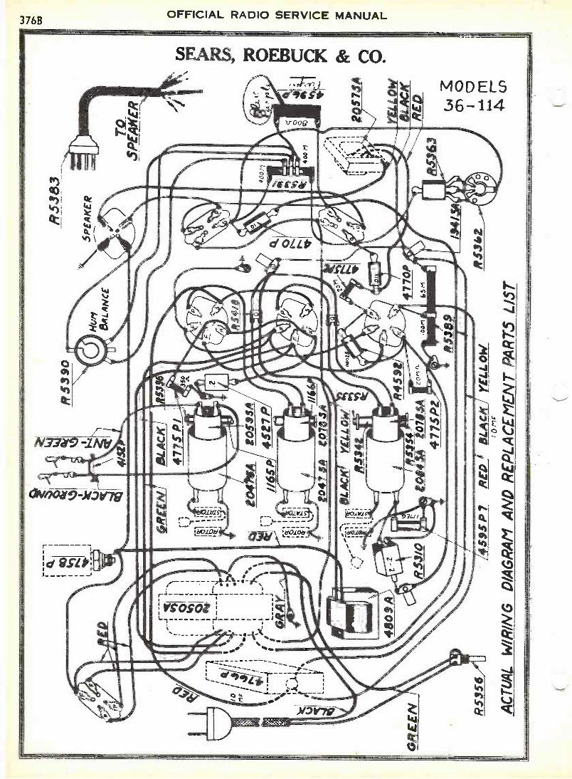
GR
GR
EE
N
8$38
9
R53
90
5,
zoot
ifm;1
AI
j
Mir
RS
383
SP
EA
KE
R
TO
_S
PE
AK
ER
;.41
RE
--
0141
4,4
477S
PZ
R53
56I
4593
P7
RE
DB
LAC
K1
YE
LLO
W0
rIF
AC
TU
AL
WIR
ING
DIA
GR
AM
AN
D R
EP
LAC
EM
EN
T P
AR
TS
LIS
T
1941
3A
R53
42
57A
YE
LLO
WA
CR
ED
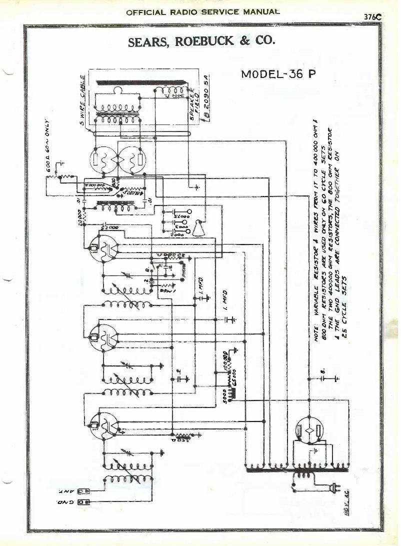
2k
//O Y
. AC
60
Z A
rra
_L
ON
LY
NO
TE
VA
R/A
BLE
AP
ES
/ST
OW
IIV
/AP
ES
fear
? /7
' TO
400
000
OH
M I
BO
O D
Nel
rE
s/S
TO
WS
AR
E U
SE
D O
NLY
ON
Go
cyt-
i_E
.5E
7-5
TH
E T
WO
400
000
OH
M r
E5/
.57c
W5,
TH
E 8
00 O
HM
,CE
S/S
TO
AI T
HE
4H
D L
.EA
05 A
AP
E c
onov
Ecr
ED
TO
6ET
HE
R O
N45
CY
CLE
557
5

OFFICIAL RADIO SERVICE MANUAL376D
0 o 0
SEARS, ROEBUCK & CO.it,
rrr(N3
JOAE___11AIR
-u- z0-11
14/
.AA AAA.V/./ OS Z.
VA.' 00 t. vuL7
77 L.,0 o
0/..fr/c/ 4:4
41--- \-17 oo0Z
MODEL 37P
rrV

AC
TU
AL
WIR
ING
DIA
GR
AM
AN
DR
EP
LAC
EM
EN
TP
AR
TS
LIS
T
RE
BLU
EB
LAC
KG
RE
EN
,erR
5734
AM
FD
R47
40
GR
AY
RE
D
R 5
872
rt 1..1
11
R 5
84IA
- 6
0 iv
R 5
875A
- 2
5 ry
R 5
3 56
YE
LLO
W,4
/ 1-1
I.
HU
M B
UC
KIN
G6.
-.)
CO
IL
GN
D -
BLA
CK
AN
T.-
GR
EE
N
R 5
508
R 5
545-
\R
5897
A
2047
5A
R58
80_,
R55
4E\
R 5
879
A
2047
5A 45
27 P
2047
5A
R 5
801
5 2 07
85A
R 5
836- R
5335
R53
42
2084
5A
I165
P
1166
P
5.14
__45
27 P
R 5
830_
,
-1 5.01
,trR
F
F?
5509
A
R 5
821
\R 6
019
SP
EA
KE
R P
LUG
SP
EA
KE
R
8426
624
5 eZ
R 5
383 W
HIT
ER
ED
BLU
EG
RE
EN
RE
D LAC
K
ceirt
$547
70
Pja
245* R58
77
O 0 r n
CM
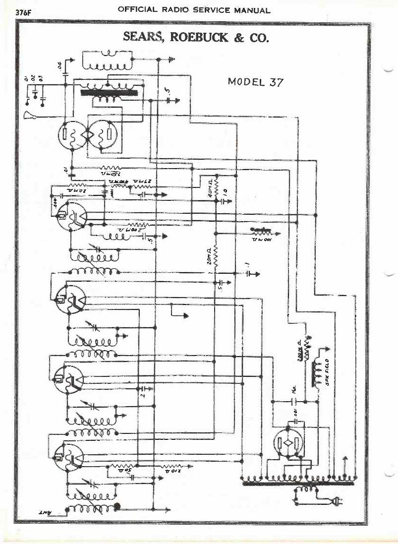
376F OFFICIAL RADIO SERVICE MANUAL
I
NJ Pr)0 0 6
SEARS, ROEBUCK & CO.
MODEL 37
.1 Mb'
,,AAAA41,Z.e OS
TZikagif v4#LZ
TT ,,,C Tr 0
WO'
O
1HO iF4'
kr,
OO
=It

280
BLU
c ED
at
R
.535
61)
8579
4
GR
OuN
DLA
O(
6 (E
N
5506
:047
1AtO
S9S
A
1165
_
BR
OW
N/1
11F
YE
LLO
WS
).8
"Fr-
1I %
II ,I
I
to
GR
EE
NB
LUE
5 M
F5
'IF
!047
5A
R55
46
ZO
$4 5
/4 R
55:4
5
NU
M B
UC
KIN
GC
OIL
R54
114
Rsa
3oR
5 75
.9
-AC
TU
AL
WIR
ING
DIA
GR
AM
AN
D R
EP
LAC
EM
EN
T P
AR
TS
LIS
T -
35
730M
SA
,
&A
CK
RE
D
8Lue
p
RE
P
R57
76
70 0
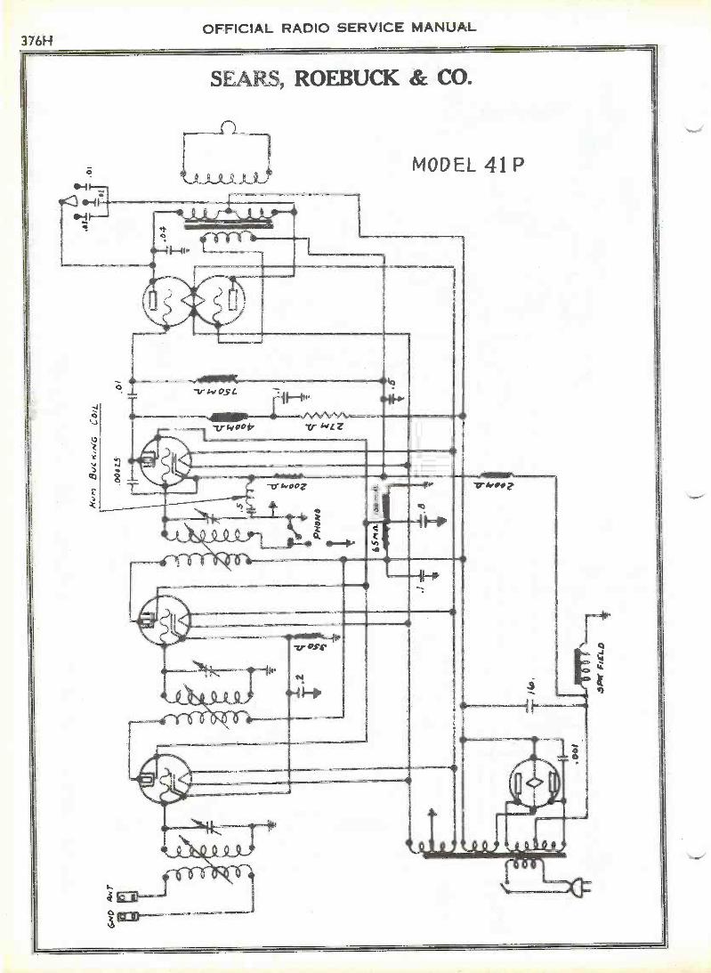
OFFICIAL RADIO SERVICE MANUAL376H

OFFICIAL RADIO SERVICE MANUAL3761
SEARS, ROEBUCK & CO.
MODEL 41RED- 280 FIL
GREEN- PRIM SWITCHBLACK - PRIM
} YELLOW- 224 et 245 FIL
YELLOW -CT FILRED - 280 PLATEBLUE -280 PLATESLATE -ELECT CATHODE
POWER TRANSFORMERR 5779A 60 .-L.R 5826A 25 -..
GREEN LEAD- S'wHUM COIL TERMRED LEAD I MFDELECT CONDENSER
YELLOW LEADR F SCREEN LilIFBROWN LEAD- . IMFRESISTOR 400MBLUE LEAD -TERM BOARD
FILTER CONDENSERR 5794. 60 CYCLE
25 CYCLE
BLACK- PLATE 1ST 245 TUBERED- +B TERMINALGREEN -GRID 2"° 245 TUBEWHITE -SPEAKER SOCKET Ial;;;-47,)RED- GNU SPEAKER SOCKET (1',V,)BLUE- PLATE- 2,-,0 245 TUBEYELLOW- TERMINAL BOARD
AUDIO, INPUT - OUTPUT TRANSFORMERR 5784 A
Of MF
AZ nf
.03rti
TONE CONTROL CONDENSERR 5777
TO STATC. . TERMINAL ONVARIABLE CONDENSER
DET 5f L. COIL U 2084 -5ATO GROUNDRF SEC COIL D2047.5ATO GND
SECONDARY COILOCT SEC COIL D 2084 SA (YELLOW SPOT)R F SEC COIL D 2047 SA (PLAIN)
ELECTROLYTIC CONDENSERR 5734 A
ANT PRIM CC4L 02069TO ANT
R F PRIM COL D -20185ATO UY 224 PLATE
ANT PRIM COILD 2059 SA TO GNO
'RFPRIM COIL2078 SATO ,8 TORN
PRIMARY COILANT PRIM COIL .0-2059 SA(YELLOW SPOT)RF PRIM COIL D-2078-SA(PLAIN)
LEAD DETAILS OF POWER & AUDIO TRANSFORMER, FILTER, TONE CONTROLet ELECTROLYTIC CONDENSERS, PRIMARY & SECONDARY RF COILS
FbWER TRANSFORMERR584I A - 60eLR 5875A - 25,-u
RED -280 FIL
YELLOW-RF FIL
), YELLOW- DET. Q 245 FIL
YELLOW -CT FIL
MODEL37
D -280 PLATEBLUE -280 PLATESLATE -ELECT CATHODE
BLACK -PRIMARYGREEN -PRIMARY-SWITCH
BLUE LEAD -.5mcdTRANS TERM BOARD
ORANGE LEAD-LomfdDET SCREEN
YELLOW LEAD- 5mfR F SCREEN
BROWN LEAD -cuRESISTOR 400 M
FILTER CONDENSER
R5901 60 CYCLE25 CYCLE
BLACK- PLATE INT 245 TUBERED- +B TERMINALGREEN -GRID 2N0 245 TUBEWHITE-GND SPEAKER SOCKET(,;;; --L-)RED SPEAKER SOCKETBLUE- PLATE- 2P.,I3 245 TUBEYELLOW- TERMINAL BOARD TRAN5F
AUDIO. INPUT - OUTPUT TRANSFORMERR 5784 B
.011041.
OTMfd
.03 mkt
TONE CONTROL CONDENSERR 5777
TO STATOR TERMINAL ONVARIABLE CONDENSER
DET. SEC COIL D - 2084 SATO GROUND'RF SEC COIL 0-2047-5ATO GROUND
SECONDARY COILDET 5E0 COIL = D-2084 -5A(YELLOw SPOT)RF SEC COIL = D-2047-SA(PLAIN)
16 MFD
ELECTROLYTIC CONDENSERR 5734 A
ANT PRI. COIL R5897ATO ANTENNA
F PRI COILS R5879AaD20785A TO UY224PLATE
ANT PRI COQ R5897ATO GROUND
RF PRI COILS R_58794020785.4 TC
4-B TER pa NALPRI MARY COIL
I - ANT PRI COIL R5897A2_-R F PRI COIL R 5879A (GREEN SPOT)
F PRI COIL 0 207854 (DET)LEAD DETAILS OF POWER 5 AUDIO TRANSFORMER. FILTER, TONE CONTROL
I et ELECTROLYTIC CONDENSERS, PRIMARY et SECONDARY R F COILS.
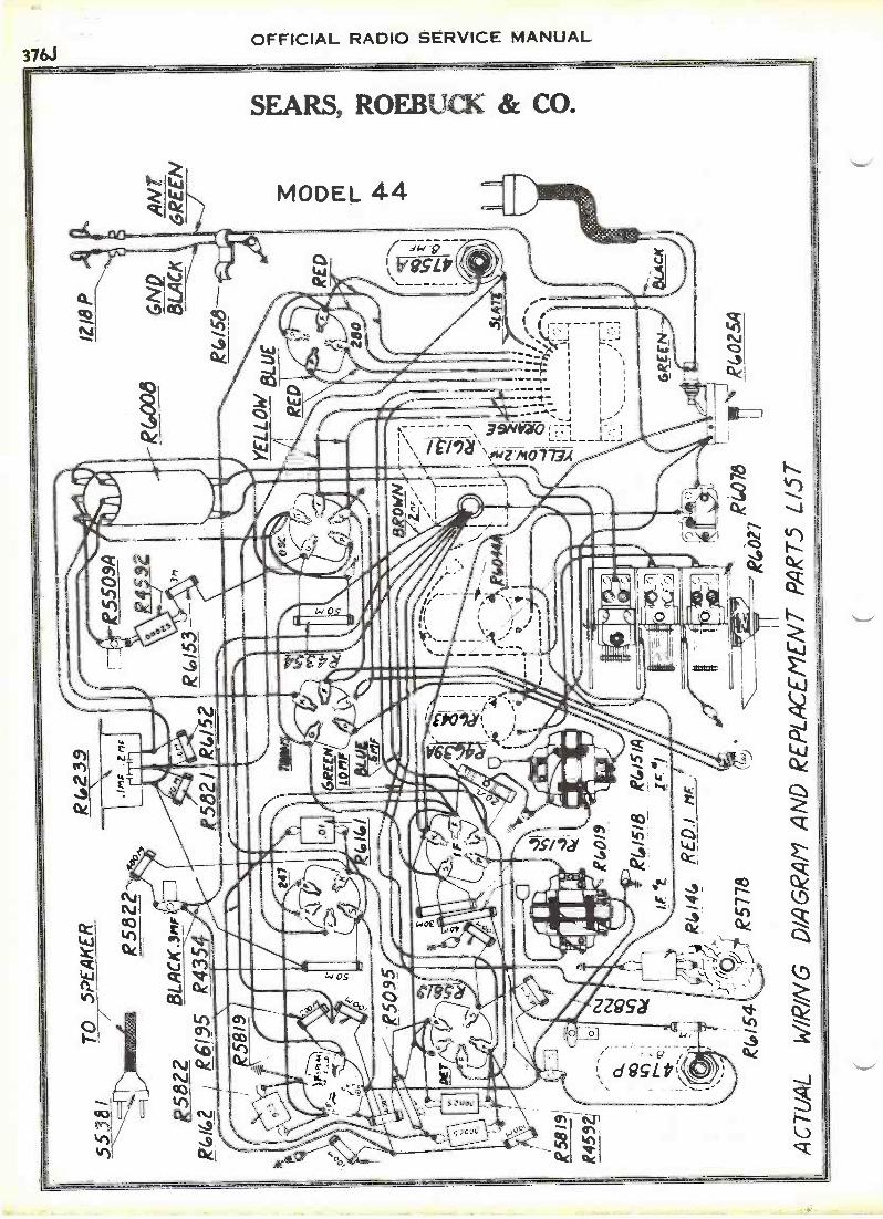
TOjS
PE
AK
ER
R58
22
8582
2B
LAC
K.3
mF
86/6
2R
6135
R43
5f
tR
5819
R58
19,
R45
94of
RG
019
R(.
23.9
MF
.Z n
c
5132
1
IMM
O
RI/5
2R
(015
3
P55
03A 3
R6,
006
1218
P 6ND
BLA
CK
R15
6
YE
LLO
WB
LUE
RE
D
BR
OW
NL
1F ----
(fir
;
3 net)
4, 4
i
1,4.
1J41
,
P4,
027
,R
4076
R(.
025A
C01
54
AC
7UA
LW
IRIN
G D
IAG
RA
M A
ND
RE
PLA
CE
ME
NT
PA
RT
S L
IST
CV
Ct.
;00
CO
IL
Oit)
;:
EU
:-
R15
10kl
4/5/
A1-
1),
IF 4
f1C
8i1
fli
_lR
1.14
4.R
E0.
1/'I
F
:(15
//,-
'-74
8577
8
RE
D
AN
TG
RE
EN
0 O

OFFICIAL RADIO SERVICE MANUAL376K
SEARS, ROEBUCK & CO.
:a
. rao
SOWER TRANSFORMER
60 CYCLE R(./(O2s CYCLE R 4445
ASSEPI IF. TRANS. AND IF
8.R6/S/0
TUNIN6 CONDENSERS
-LEAD .000ERED .imr irs*ResiorseDLL JagXE SIZUNGIMP Aortr NT Cant.MACK Jigs ex Aroma aPACK yoa11,11 RE.
r.11", IF Fre SCREENLIPILZ .2,10: IF CATIi.
FALTER CONDENSER CAN - Cevinfi
86131
STANKTIRM.
SUPTSSOR CAVA
ANTE. IL 6043COA* STATOR
414 *ITR.F. COIL R 1.044A
415S II 47545(wow -also)ELECTROLYTIC CONDENSERS
PICK -410 CAM, OR srameTRAIlscAnse
OSCILLATOR CO/L. R6008
SUPPRESSOR Cava RZie.110104"
11411106C
TONE CONTROLCONDENSER R4/44
4EAD DETAILS OF powER TRANSFORMER-IP:TRANS.-1F TUNING CONI2- FILTER. TONE CONTROL.gl4CTROLYTiC SuPPRESSo.R CONDENSERS- R.F. -ANT IOSCILL,ATOR COILS MODEL 44

00 d

8552
2 0 0
.003
00
RW
8
co07
3 T
o 5P
GR
EE
N.5
7F.
5830
8575
8
8577
8
ER
R 6
/ 52
R S
2/
RI'D
.1'IF
ii)(0
51A #I
1R10
01i1
Nat
o
R(.
027
AC
TU
AL
WIR
AIG
DIA
GR
AM
rf PIK
MR
e550
3A
up
R41
53
8435
4
59 JL o
OR
A
YE
LLO
W
BLU
E 280
RE
D
I; ;
i1lb
1.77
iT
11-
1111
441,
L7
'
IIK
AII
6110
0
lob
i
'0 ie62
18/4
.;s
R(
2 /0
GR
EE
N
R(.
025A
RE
D
BL
AC
AN
r
GR
EE
N
r-
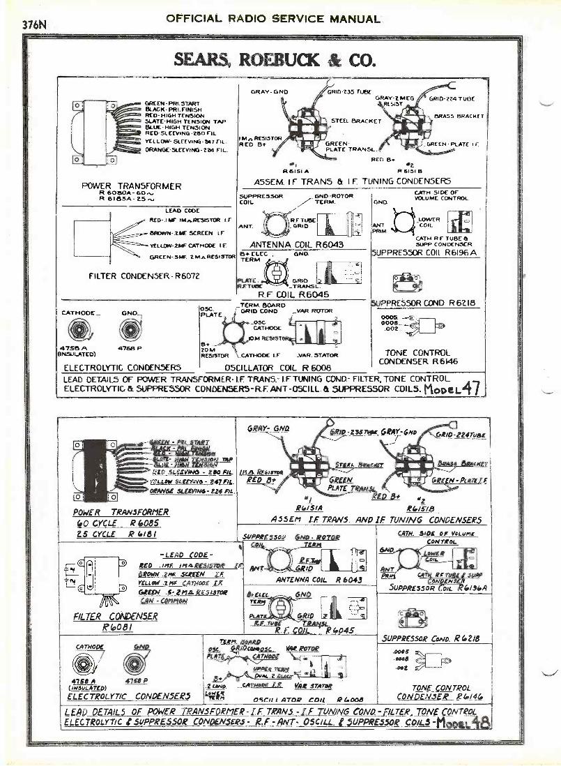
376NOFFICIAL RADIO SERVICE MANUAL
1
SEARS, ROEBUCK & CO.
GREEN -P121.5TARTBLACK- PRI.FINISHRED- HIGH TENSIONSLATE -HIGH TENSION TAPBLUE HIGH TENSIONRED SLEEVI NG -280 FILYELLOW- GLEEVING -247 FIL.
ORANGE-SLEEYI NG - 224 FIL
POWER TRANSFORMERR 6O8OA-6O818SA-
LEAD CODE
RED- IMF IMA.RESISTOR I F
BROWN -.21F SCREEN I.F
YELLOW- 2114F CATHODE I E
GREEN- SW. 2 MnRESISTOR
FILTER CONDENSER- R607?
CATHODE_ GND-I
4758 A 4768 P(INSULATED)
OSC.PLATE
8.20 MRESISTOR ,_CATHODE I F
GRAY- GND
Mn RESISTORRED Bi-
GRID-235 TUBEGRAY -2 MEG
RESIST
STEEL BRACKET
GREENPLATE TRANSL.
RED B.sl 42R 6151A R 615113
GRID -224 TUBE
BRASS BRACKET
GREEN PLATE i
ASSEM. I F TRANS & I F TUNING CONDENSERS
SUPPRESSORCOIL
ANT.
.GND-ROTOR7- TERM.
ANTENNA COIL R60438. ELEC , GND.TERM
PLATE GRIDRF TUBE _TRANSL
R F COIL R6045TERM. BOARD
1 -GRID COND. _VAR. ROTOR
_OSCCATHODE
OM RESTS
.VAR. STATOR
ELECTROLYTIC CONDENSERS OSCILLATOR COIL R 6008
z
c
GND
ANTPRIM
CATH SIDE OFVOLUME CONTROL
LOWERCOIL
CATH R F TUBE aSUPP CONDENSER
PPRE55OR COIL R6196A
a 0
PPRESSOR COND R 67.18
00050008.002
TONE CONTROLCONDENSER R6146
LEAD DETAILS OF POWER TRANSFORMER- COND- FILTER, TONE CONTROLELECTROLYTIC ec. SUPPRESSOR CONDENSERS-R.F. ANT -05CILL. & SUPPRESSOR COILS. MODeL47
V4RAW TEN51414-ibmaLrethtm nisp
RED .5LEEVING - 280 FIL.
yri-LoW SLEEVW6 - 247 AL.
ORANGE SLEEWN6- 224 AL.
POWER TRANSFORMER
(.0 CYCLE R 408525 CYCLE R 4181
1 TED 8#RGISIA 841518
ASSEll I.F. TRANS. AND IF. TUNING CONDENSERS
SOPPRE55of 6No ROTOR
-LEAD CODE -RED F INA Ri-313TOR tF-OROWN .ZMF SCREEN LE:
YELLOW .2 nig CATHODE IFGREEN .5- VIAREShsToRCAN COMPloN
FILTER CONDENSERPlo081
CATHODE GND
4758 A 4758(INSULATED)
ELECTROLYTIC CONDENSERS
r GRID
ANTENNA COIL R 6043
8.11E4 6N
MIN
PLAT(
TE_
GRIDlieF. ruff 7.:Rmiu.
F. COIL_ R 6045
6ND
CAIN. 3/DE OF YoLuncCONTROL
OVERCoal.
ANTpf_tn CA PP
CON.V NSI-RSUPPRESSOR Coll. 6194A
Tun 5oARD05C. Vilkomosc. VW ROTOP
ATE CATHODE
uPPEit TERlt
5.e'sA"-DvAL Z pLetA
.2 <AND. carNevc I.F. VAR snowOM
OSCILLATOR COIL R Good
0
SUPPRESSOR COND. R(.218
.0006Heeoet
TONE oNTROLCONDENSER R(0144
LEAD DETAILS OF POWER TRANSFORMER - I F TRANS. -I F TUN/N6 COND.- FILTER, _TONE C_ONTRoL
LELECTROLY-ricSUPPRESSOR CONDENSERS - R.F - ANT- OSCILL. 1 SUPPRESSOR COILS -Moon
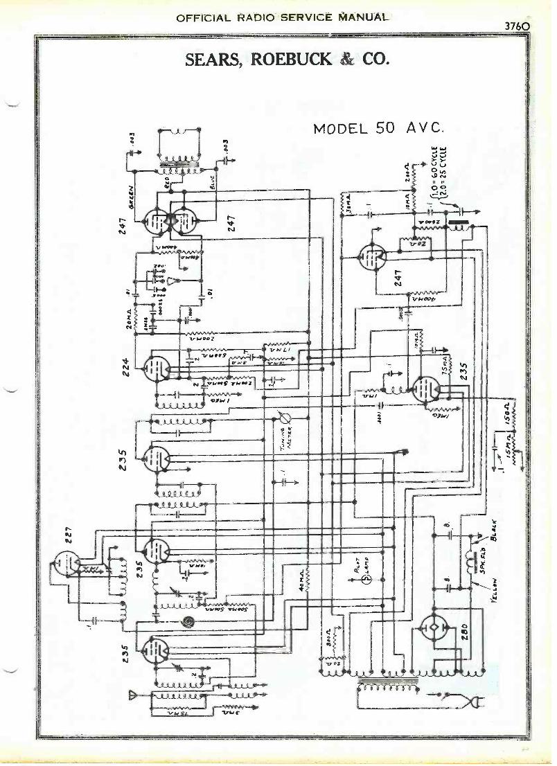
II
Z85
-pus
tudi
u
Z80
ZZ
7
-8
5P(
cLo
re4-
Lool
BLA
ca,
Z35
ZZ
420
mA
247
-II 15
11.1
.15
0-a
Ane
rnn-
4-A
nwv,
--
= G
O C
YC
LE
25 C
YC
LE
0 a fn O
to
w 0

GR
ID I
.F. _
&__
_ I.
F.
PLA
TE
_PL
AT
E I
.F.
'w
.
BL
UE
-HO
GH
TE
NSI
ON
PL
AT
E 2
80-
---.
RE
D -
HIG
H T
EN
SIO
N P
LA
TE
260
SLA
TE
-C
EN
TE
R T
AP
H.T
.CA
TH
.EL
EC
T.
-R
ED
-20
0 F1
L.
RE
D-
280
FIL
-G
RE
EN
-PR
IMA
RY
YE
LL
OW
/SU
PPL
Y T
ER
MFa
RE
EN
500M
RE
SIST
OR
,,
\RE
D'
/ GR
ID 2
35A
VC
GR
AY
;/
-GR
EE
N
L .
A .1
17k
TE
EL
ii,64
,11
1111
41
Arl
1W11
111
BR
AC
KE
T%
Mk
I i
IB
LAC
K -
PR
IMA
RY
WH
fT
E F
l L. 2
47A
.V.0
1011
.411
412
ME
E!
RE
SIST
OR
-
GR
AY
Ili
1111
1111
.11:
Al.
,.
WH
ITE
- FI
L. 2
47A
.V.0
OR
AN
GE
- Fl
L .0
3C.,
R.F
:,TR
AN
SI.a
L E
OR
AN
GE
- FI
LM
:, R
F,T
RA
NSL
AIF
,li.
A=
.11,
.....
"--.
11.1
1111
11/
_BR
ASS
+13
TE
RM
INA
LIi
ii,".
5T
E T
RA
NS.
tilL
igB
RA
CK
ET
YE
LL
OW
-FIL
TA
7, O
UT
PUT
It 2
35 A
MC
'.Y
EL
LO
W-
F1L
2A7,
OU
TPU
T a
235
Ay.
C.
PO
WE
R T
RA
NS
FO
RM
ER
R 6
248A
- 8
0,v
R 8
249
A -
23.
..
RE
D',.
...G
RE
EN
GR
ID 2
24Y
EL
LO
W
sei
otR
6151
C-
R 8
327A
A55
EM
. I.F
. TR
AN
S ft
.I.F
. TU
NIN
G C
ON
DE
NS
ER
S
OR
AN
GE
-.O
03 M
F.-
PLA
TE
2,47
OU
TPU
TI
OR
AN
GE
.003
ME
-PL
AT
E 2
47 O
UT
PUT
02
SUPP
RE
SSO
RC
O I
L ._
___
GN
a R
OT
OR
TE
RM
.G
N a
_G
N D
.
//.Y
EL
LO
W -
.2 M
F 10
M R
ESI
STO
RG
RE
EN
- .7
MF.
- 2
M R
ESI
STO
R,y
,...._
b_
,_
BA
NT
.El
LOW
ER
a.
7,-,
, gi
WH
ITE
-I
MF
- SO
O M
RE
SIST
OR
/,....
..R
ED
- .
I M
F -
L F
.. PL
AT
E S
UPP
LY
TE
RM
.0
I I
I 0
RG
FRTU
BE
=PR
IM_
._. C
01 L
I1
at.
,
- -
- -
--7.
- -
-B
LU
E -
. I M
F -
CA
TH
OD
E 2
35 M
a
\''''''
",,,,
ZH
.,,,4
-:"-
-....
..
BL
UE
- . I
MF.
-SC
RE
EN
235
MA
C.
BL
AC
K -
.IM
F -
2M R
ESI
STO
R
AN
T' i
lil.0
1°A
-e-1
-C
AT
H. R
.F T
UB
E4
WM
CO
ND
EN
SER
SLA
TE
- IM
F-4
00M
RE
SIST
OR
BR
OW
N-.
I M
F -
I M
RE
SIST
OR
AN
TE
NN
A C
OIL
R 6
043
SU
PP
RE
SS
OR
CO
ILR
619
6A
ae--
- R
ED
- +
5 T
ER
M.
.._.)
- -
--
-A
CC
-BL
AC
K -
IF P
LA
TE
TE
RM
.46
.M
AR
OO
N -
OA
TH
. EL
EC
TC
ON
D.F
ILT
ER
CO
ND
EN
SE
R-
R 6
238
)
,BO
OM
RE
SIST
OR
\__
GR
IDT
RA
NSL
AT
OR
RA
TE
- R
EST
AT
OR
, TU
NIN
G C
ON
D.
TU
NIN
G M
ET
ER
R 6
241
CH
OK
E C
OIL
,R
624
5A, -,
,, \,ii
(it
CA
TH
OD
EG
ND
.
on, N
NJ
OM
I
-
.
_IP
.
(---
)C.
\,
/6;
5 ,(
YE
LL
OW
-C
AT
H. T
RA
NS.
BL
AC
K -
CA
T H
. OS
C.
I. F
. PL
AT
ESU
PPL
Y T
ER
M.
-400
M R
ESI
STO
R
TR
AN
SLA
TO
R C
OIL
R62
52 B
:.....
4758
A47
58 P
(I N
SUL
AT
ED
)
,../..
40 M
RE
SIST
OR
FIL
TE
R C
ON
DE
NS
ER
ELE
CT
RO
LYT
IC C
ON
DE
NS
ER
SR
623
9
'LE
AD
DE
TA
ILS
OF
PO
WE
R T
RA
NS
FO
RM
ER
- I.F
.T
RA
NS
. -1.
F T
UN
ING
CO
ND
.- F
ILT
ER
CO
ND
.-E
LEC
TR
OLY
TIC
CO
M)
- A
NT
EN
NA
,5U
PP
RE
S5O
R,T
RA
NS
LAT
OR
AN
D C
HO
KE
CO
ILS
- T
UN
ING
ME
TE
R.
0 rr -n O
0 Pq Ro

32 L9
T3
32
L9 L9
32 L9 L9
L4 L5
C4
EL4
51. A
TE
.
Gtr
in
5-7-
7474
1T
i32
R6
4
5kow
N.
32
5
223o
Ioo
2
3700 1 2
174X
2
R. F
. C e
-i A
5,51
5.LI
, L2
L3.
PA
RT
(4.
L5,
h.=
IC
1. C
2. C
.), C
4 ,0
C 1/4)
Iv!.
Cov
Otn
isfR
s00
I2
-*
2/81
-/0
00/d
o/9
71R
l .e5
0 0)
-111
5.1
' 209
1R
220
.00_
0,-
015
-41
2079
SP
E-c
b.u.
..
R4
= 1
500,
0ki
t-75
0 X
2/34
R5=
250
023
/9R
6t5
0000
a"4
232
1 S
ole
AL
Ti
"18
89
Cc)
R.F
CN
oK-E
7-22
590 4
g18
.T
2
19.2
15
^2o9
4o 15
33T
o-i2
Arr
o N
6.T
3
40.I
.VE
TY
CU
T/C
AL
IfO
rP 8
AL
AN
ct N
rIte
IS
722/
04
040
RIP
Pa.
O
Pow
UN
IT.
PA
RT
227
5.
GO
CY
CL
::Z
i'Aoy
ti.L4
*:0
J'A
fr.2
129
RE
4uLA
roq3
{25
2."
6-20
d20
44
SIN
4LE
/Q M
r. C
ovo.
iAiS
eR.5
Pr/
533,
;IS m
ifeov
otho
or P
r2,3
el
vrL
ASN
,--
----
-21
5
FIL
TE
Rfo
NO
E 1
415E
R i0
00 v
.F
LAS
H.
PA
RT
*273
-2
TA
PP
EO
PrR
obi
RL-
51.5
Tok
50
Win
-4
4736
4.
1120
GL
-R5
Aov
AN
cco
CH
AS
SIS
PO
wzQ
UN
IT
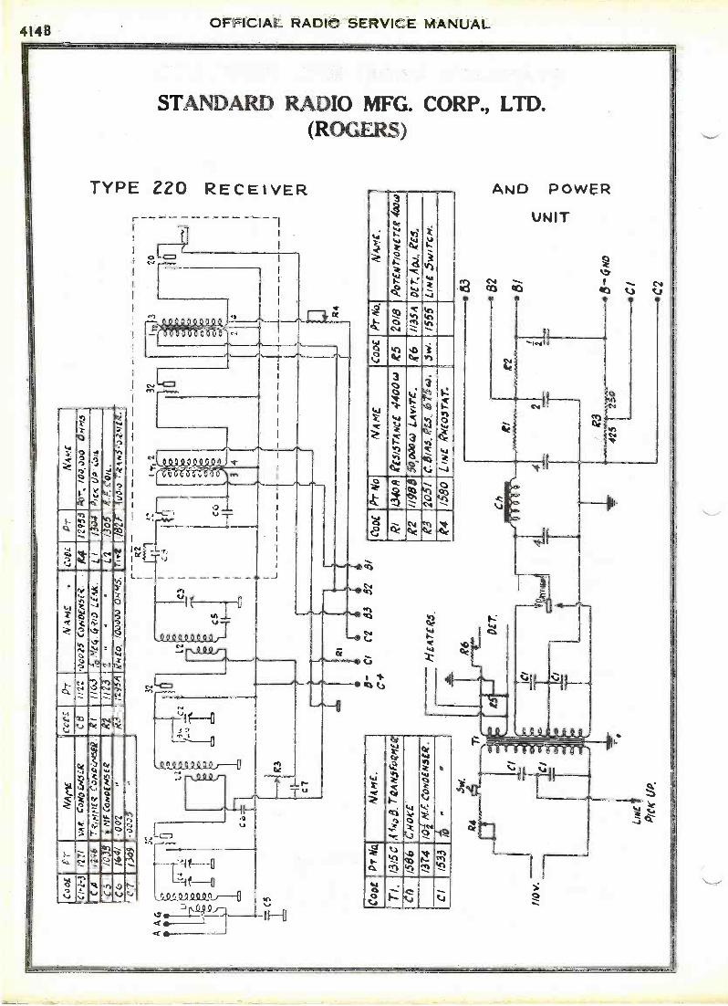
Coo
LP
rA
IAriE
CC
D_
1-r
N 4
ME
.C
orti.
0-r
A'A
mC
CI -
1-3
/27/
VA
R, C
oN0F
/445
:-.R
C8
1122
oco2
5 C
ooD
Eirs
ri..
1412
953
Ar-
, 10o
,000
OH
n.5
CA
1296
7' 4
/Nt7
(4 C
otai
nd8R
el11
63zt
o M
e4 4
.<'1
0 LE
ilg
-L
1/3
o4',c
LIP
.".)
14.
C5
/C35
iisIF
CoN
etw
si 4
R2
1123
2 -
L2O
afer
Con
..c6
1641
002
113
/295
4R
HE
o. 1
0000
4) O
N45
.T
oPt
152F
4uo,
o744
,..S
co,?
.444
.C
700
9_0
005
..r
-R
2
A A
4 1,4
:4 c==
1c5
C
1.2
P
32
12.3
C2
12C
3
C5
CT
CC
Coo
eP
r N
aN
AM
E.
Ti.
1315
C,4
1,40
5.71
2Afo
roan
teC
h15
-131
:7-C
hioc
t
1374
101
NJ:
CoN
DE
NS
ER
.
CI
1533
76
"v.
E
RI
3
Ti 2 4
5- C
lC
253
5751
C#
H E
AT
ER
.5.
R6
I
OC
T.
2
Coa
tP
r N
oN
AM
EC
orm
Pr
No.
NW
.R
I1.
340R
el-5
1574
sec
4400
(4R
520
/8P
ortm
rla
par
te 4
xwR
211
989
50,0
004)
LA
wre
".ge
,11
35,1
DE
7:, A
DJ.
, ZE
.5,
R.;
205/
C. e
ms.
as.
, 675
4o.
iw/5
55LI
NE
.5w
ircH
.'4
/580
LIN
E I
NE
OJT
AT
.
83
82
Ch
R1
48/
41_
42
c41T
Q3
*--*
Fi"-
i1O
''8O
NO
4
CI
C2

OFFICIAL RADIO SERVICE MANUAL4I4C
STANDARD RADIO MFG. CORP., LTD.(ROGERS)
TYPE 250 RECEIVER AND POWER UN IT
cc
Re
tiO
O14)
{",1
9-1.3
OCC
CAI
ri
OOO00
Or
RVVr1sto (-4
NsNs
VIa
tCCr)cc
L
(1'
*4O
Ott
OC
O
411
0
tifq 0
oc
.v.e..
7
4`4-ik
-1-..
2,./ik00
viv02
k-r,"s IC4
1---
Nr)
tki2.-
'---1
01..n1
to....1:::)
=7
Invl4)
',IZ.1'
3.73
1-
'4
-
v1vi
,L;-I->.C',4
30*4.
,,4
kr)t,.'0%/),...atedip
4C.
ez)
i--.-c$--
oWV-,-a,
teki?
02I-0
Q1C1'In_
`rcla0,
..0r4.1n
CI1)to
W
C.)
01. era
Ot
eiekoZ
eie4.44r).0..,,
L./ ..1 044%.
4t4C3'k
t.I .
k'
--: ;84., V -, -19.2) r
Ni. 01- ON 13 .r it,.
....40 -- ..r. kQ-lk k j
C.. ,
csa
11
5O

4I4DOFFICIAL RADIO SERVICE MANUAL
6
STANDARD RADIO MFG. CORP., LTD.(ROGERS)
400 SERIES RECEIVER AND POWER UNIT
I
L3
R6
R.14: CHA5515,
1.4 '00025
111.47j.002L3: V *HI--.
T2 --. 7'3
.00025
J000c..)
2..._43/-,
3N
82
Pr No 2034 L3 - L43000 C)-rfr4 REGrivEvcrioni CONTROL PT No 20/7
/50,000 if VoLumr CONTROL If " 20/
71 18073 :-R6 = 400 Oqi-r5:-
A-T.0R
ht 5.HO V.
LINE Prat UP
81. c2
Pr No 2035 Ch PT No /946
" I82F.2/66.
POWER
-L4 :2-4
C
331 t 32
i31
C2
3PECiriCATION.5.Potn ER UNIT role TN i5 PowcR -ruec.
UN/vi:z5q._ (25 4%., 6o CYCLE) PA,27 2260Ch PAR T 2271.
{25 CYC TYPE C-20 "Z.f:c/LA-712,2leEOL A TORS..
CO "
Rl ® 7000w R2 = 2opoow e3= /390w R4=5000ow L4v777.-
25ov. 52= Nov. 81=30V. C2= 500. 10i M-F.CONO.
7Lo COND -500V. -Li90,-( TEST PT 2255.
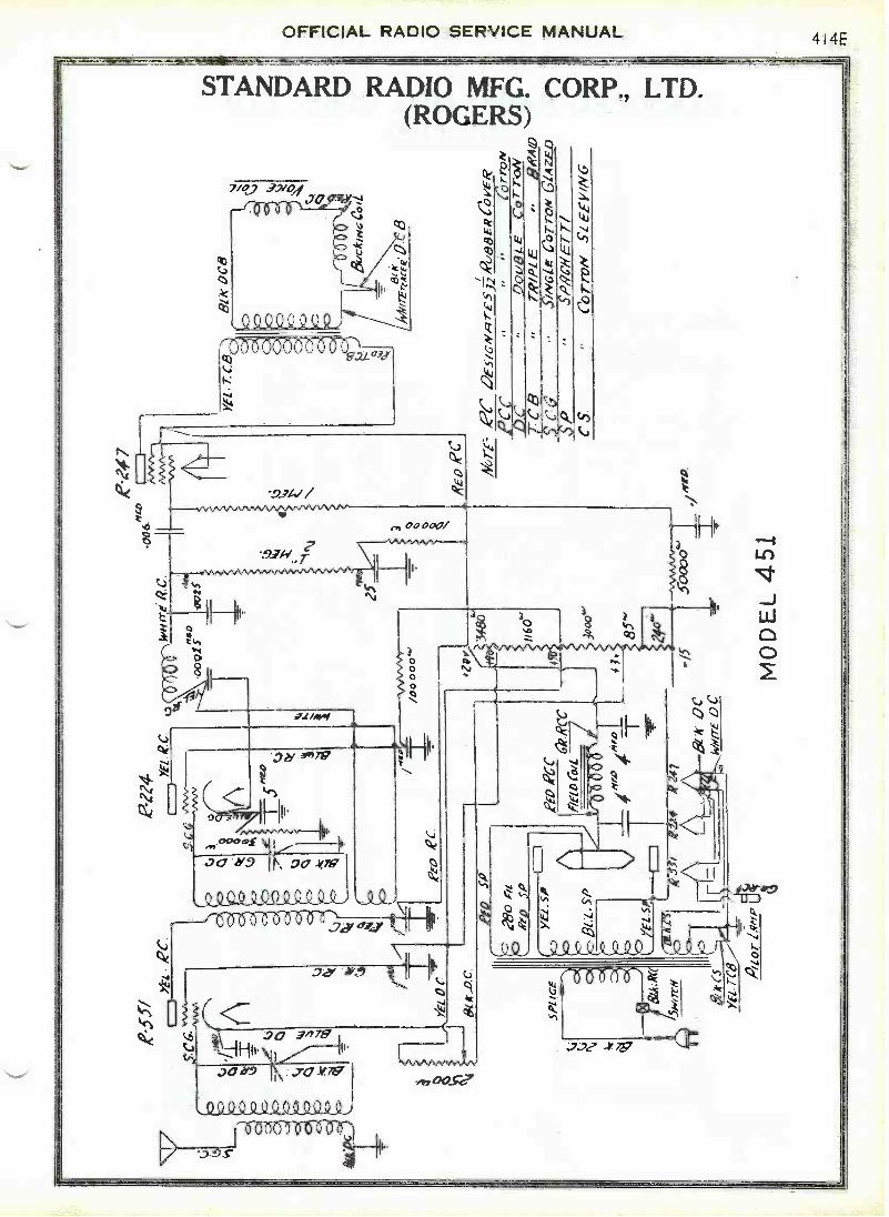
81 A
' _D
r
{9a
3180
I160
"
41. -/5
.5-0
000"
MO
DE
L 4
51
8/k
008
RE
D P
C
Nor
rz2
e5/6
w,,/
rE
53-2
, Rua
E R
R
t,cC
CC C
CS
Cpr
roy
_9(2
09L
EC
ori -
0NT
R/P
I EB
RA
ND
Sin
/Cie
Cor
rav
GlA
zf40
S P
RO
/ ET
r/
Co
rroN
SI E
E V
/N

-1.1
11S1
_7
70.
R,v
r
CN
O
9 .r
s
LTi
GR
OG
CR
7c8
6-17
rc'
s
00 YE
!. D
C
BIA
- O
C
A25
.57 Y
E[ R
C
46,-
,PC
De-
5,6,
vgrf
seo
sgai
avE
R/P
CC
3771
2WD
c4.
OO
U/3
LEC
orT
ON
PS
ioA
cm
Er
-r,
6-ar
roN
Ste
r v
NG
467E
- A
LL D
C V
oLT
AG
ES
ME
A.S
ciR
0 T
oO
RO
VN
O A
NO
1?C
. Vol
rAce
3.11
015c
/RE
O /f
ir S
ocxe
rs
c' c
c
5-0,
.t222
4I
64 T
r 13
^A
.-
E0
,l'E
co R
C
CA
iort
Re
(5e'
ff°1
I
14,I
err' L
pGM
---4
I -
If 5
51,4
Aio
Yec
.C
aSL
UE
s
MO
DE
L -
545
6",?
0.0
A72
15- )f
,ZT
C5
pap
RIO
5fi
Fd
air
kCc
5.01
tce
RC
CR
RC
Reo
RC
P/E
LD
C0 0 r" 1-
4
ew

OFFICIAL RADIO SERVICE MANUAL578C
RN
c
Airirr
STANDARD RADIO MFG. CORP., LTD.(ROGERS)
MODEL 640
111.R
cc 6-0 re04,..,m,
SIs re ICK
/914 o frf
CC Yzi
1-`
Itto%%%%%%
BGr
Ba ac
04e so reir
Mort? F
kir
COO
f1/4sl f 4
AKSWAY:".Soerer 11
2 124fH
0:
Di
NOTE- gi.4" ,,, 17 Aloer C0770# CoyerZer0 /OFFDE5/eNilliS A-zeirdicR anc.ern W/RE 1)-
iP C 5P 5"w/err/.CorroW gef/DED ,w/,PE
Via2 mu l 30
ceLi
MODEL 831
CitTnw .f.etekehvc-TR/IIE COTTON AfAVT.
RI,
It
Wo780
rr2Ira
2804rt
eto
454)
4
IC 4 litairKyrn:,4-,
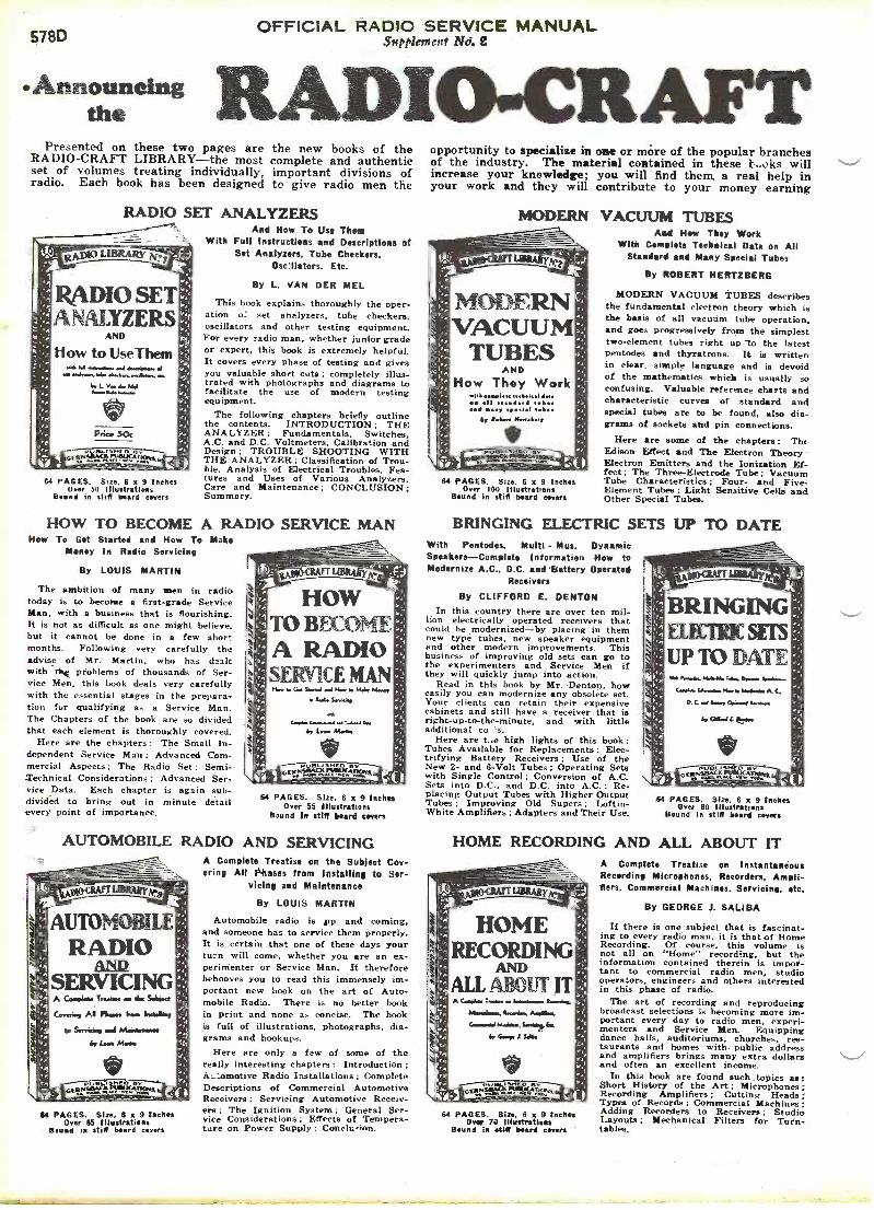
OFFICIAL RADIO SERVICE MANUAL578D 51ftPlettrcitt No. e
AUTOMOBILERADIO
ANDSERVICINGA (molds Tnsmsa a tia Salaam
Cosarins Al Pim. Ms. InatalMe
S4 PAGES. Size, 6 x 9 InchesOver 65 Illustrations
Bound in stilt beard corers
-Announcing RADIO -CRAFTthePresented on these two pages are the new books of the
RADIO -CRAFT LIBRARY-the most complete and authenticset of volumes treating individually, important divisions ofradio. Each book has been designed to give radio men the
RADIO SET ANALYZERSAnd How To Use Thee
- With Full Instructions and Descriptions ofSet Analyzers. Tube Checkers,
On'Haters. Etc.
RADIO SETANALYZERS
AND
How to UseThemAL 54 . mai df elA .1
o'iL Va tior 55416ile
Price 50c
C4 PAGES. Size. 6 x 9 InchesOver 50 Illustrations
Bound in stilt board corers
By L. VAN DER MEL
This book explains thoroughly the oper-ation u: set analyzers, tube checkers,oscillators and other testing equipment.For every radio man, whether junior gradeor expert, this book is extremely helpful.It covers every phase of testing and givesyou valuable short cuts : completely illus-trated with photographs and diagrams tofacilitate the use of modern testingequipment.
The following chapters briefly outlinethe contents. INTRODUCTION: THEANALYZER: Fundamentals, Switches,A.C. and D.C. Voltmeters, Calibration andDesign : TROUBLE SHOOTING WITHTHE ANALYZER: Classification of Trou-ble, Analysis of Electrical Troubles. Fea-tures and Uses of Various Analyzers,Care and Maintenance; CONCLUSION:Summary.
HOW TO BECOME A RADIO SERVICE MANHow To Get Started and How To Make
Money In Radio Servicing
By LOUIS MARTIN
The ambition of many men in radiotoday is to become a first -grade ServiceMan, with a business that is flourishing.It is not as difficult as one might believe,but it cannot be done in a few shor.months. Following very carefully theadvise of Mr. Martin. who has dealtwith r4se problems of thousands of Ser-vice Men, this book deals very carefullywith the essential stages in the prepara-tion fur qualifying as a Service Man.The Chapters of the book are so dividedthat each element is thoroughly covered.
Here are the chapters: The Small In-dependent Service Man ; Advanced Com-mercial Aspects: The Radio Set ; Semi -Technical Considerations; Advanced Ser-vice Data. Each chapter is again sub-divided to bring out in minute detailevery point of importance.
usio-citAfTLIBRARyfre
HOWTO BECOMEA RADIOSERVICEMAN
Or or. Mr...
64 PAGES. Size, 6 x 9 InchesOver 55 Illustrations
Bound In stiff board covers
AUTOMOBILE RADIO AND SERVICINGA Complete Treatise on the Subject Cov-ering All Phases from Installing to Ser-
vicing and Maintenance
By LOUIS MARTIN
Automobile radio is ip and coming.and someone has to service them properly.It is certain that one of these days yourturn will come, whether you are an ex-perimenter or Service Man. It thereforebehooves you to read this immensely im-portant new book on the art of Auto-mobile Radio. There is no better bookin print and none as concise. The bookis full of illustrations, photographs, dia-grams and hookups.
Here are only a few of some of thereally interesting chapters: Introduction ;A:__omotive Radio Installations : CompleteDescriptions of Commercial AutomotiveReceivers : Servicing Automotive Receiv-ers : The Ignition System: General Ser-vice Considerations ; Effects of Tempera-ture on Power Supply : Conch: inn.
opportunity to specialize in one or more of the popular branchesof the industry. The material contained in these 1,,oks willincrease your knowledge; you will find them a real help inyour work and they will contribute to your money earning
ti
,"^s,
MODERN VACUUM TUBESAnd Hew They Work
With Complete Technical Data on AllsopKIATTLIBBARyAr..2 FJ
MODERNVACUUM
TUBESAND
How They WorkwillItte do.
.11 stsoliard eves..S .petrol t
Sy RA.. Htti.loe,
84 PAGES. Size. 6 x 9 InchesOver 100 Illustrations
Bound in stiff beard corers
Standard and Many Special Tubes
By ROBERT HERTZBERG
MODERN VACUUM TUBES describesthe fundamental electron theory which isthe basis of all vacuum tube operation,and goes progressively from the simplesttwo -element tubes right up to the latestpentodes and thyratrons. It is writtenin clear, simple language and is devoidof the mathematics which is usually soconfusing. Valuable reference charts andcharacteristic curves of standard andspecial tubes are to be found, also dia-grams of sockets and pin connections.
Here are some of the chapters: Th,Edison Effect and The Electron TheoryElectron Emitters and the Ionization Ef-fect: The Three -Electrode Tube; VacuumTube Characteristics ; Four- and Five -Element Tubes: Light Sensitive Cella andOther Special Tubes.
BRINGING ELECTRIC SETSWith Pentodes, Multi - Mus, DynamicSpeakers-Complete Information How toModernize A.C., D.C. and battery Operated
Receivers
By CLIFFORD E. DENTONIn this country there are over ten mil-
lion electrically operated receivers thatcould be modernized-by placing in themnew type tubes, new speaker equipmentand other modern improvements. Thisbusiness of improving old sets can go tothe experimenters and Service Men ifthey will quickly jump into action.
Read in this book by Mr. Denton, howeasily you can modernize any obsolete set.Your clients can retain their expensivecabinets and still have a receiver that isright -up-to-the-minute, and with littleadditional co s.
Here are t.,e high lights of this book:Tubes Available for Replacements ; Elec-trifying Battery Receivers Use of theNew 2- and 6 -Volt Tubes: Operating Setswith Single Control ; Conversion of A.C.Sets into D.C.. and D.C. into A.C.: Re-placing Output Tubes with Higher OutputTubes; Improving Old Supers: Loftin -White Amplifiers ; Adapters and Their Use.
HOME
UP TO DATE
64 PAGES. Size. 6 x 9 InchesOver 80 Illustrations
Bound in stiff board corers
RECORDING AND ALL ABOUT IT
HOMERECORDING
D
ALL ABOUT ITA Complo Tv* soih
Wwgtiamek 1.414,
Came.6.1 Mime. So*"Sr GA, I Sao
64 PAGES. Size, 6 x 9 InchesOver 70 Illustrations
Bound in 4444f beard corers
A Complete Treatise on InstantaneousRecording Microphones, Recorders, Ampli-fiers, Commercial Machines. Servicing, etc.
By GEORGE J. SALIBA
If there is one subject that is fascinat-ing to every radio man, it is that of HomeRecording. Of course, this volume isnot all on "Home" recording, but theinformation contained therein is impor-tant to commercial radio men, studiooperators, engineers and others interestedin this phase of radio.
The art of recording and reproducingbroadcast selections is becoming more im-portant every day to radio men, experi-menters and Service Men. Equippingdance halls, auditoriums, churches, res-taurants and homes with public addressand amplifiers brings many extra dollarsand often an excellent income.
In this book are found such topics as:Short History of the Art; Microphones ;Recording Amplifiers ; Cutting Heads:Types of Records ; Commercial Machines:Adding Recorders to Receivers ; StudioLayouts ; Mechanical Filters for Turn-tables.

OFFICIAL RADIO SERVICE MANUALSup filebtent No. 2 578E
LIBRARYcapacity. Read these books during your spare time at home.
The authors of these books are well-known to everybody.Each one is an expert radio man; an authority on the subject-each is thoroughly familiar with the field which he represents.
THE SUPERHETERODYNE BOOKAll About Superheterodynes
How They Work,' How to Build and Howto Service Them
By CLYDE FITCH
There is no more fascinating a subjectin the large array of radio circuits thanthe famous superheterodyne circuit. Ithas taken the world by storm, and todaypractically all modern receivers employthis principle of design. Whether youare a Service Man or experimenter, first-hand kno,. ,o,g5. about the construction ofthese receivers is very important. Thebook on Superheterodynes gives underly-ing principles of their construction, rightfrom the very first set made. Masteringthe fundamentals of this circuit will en-able you to build or service any receiver.
The following is a short list of con-tents: Basic Principles of the Superheter-odyne; The Oscillator ; First Detector ;Single Dial Tuning Systems; Interme-diate Amplifier; Second Detector, AudioAmplifier and Power Supply; CommercialSuperheterodyne Receivers; ServicingSuperheterodynes.
64 PAGES. Size, 6 x 9 InchesOver 60 Illustrations
Bound in stiff board covers
RADIO KINKS AND WRINKLESFor Service Men and Experimenters
A Complete Compen'um on the LatestRadio Short -Cuts and Money -Savers
By C. W. PALMER
It often becomes necessary for experi-menters and Service Men to call upontheir memory .ar some short cut or radiowrinkle that will solve a problem quickly.In busine "short cuts" mean time andmoney saved, and to the Service Man"time saved" means money earned,
This book is a compilation of importantradio kinks and wrinkles; the entirecontents of the book has been selectedwith great care in order to discuss onlysuch items as are constantly used today.
Here are some of the more importantchapters: Introduction : Servicing Short -Cuts ; Testing Equipment and Meters;Vacuum Tubes and Circuits; Volume -control Methods; Amplifiers and Phono-graph Reproducers; Power Supply Equip-ment Coils and Tuning Circuits; ShortWaves; Loud Speakers; Tools and Ac-cessories.
spotatArTLISRARYpe7
RADIOKINKS
WRINKLESFor Service Men and
ExperimentersA
5110,.C* mai PAma,SArces
6, W P L0
trg:=1.Mc(i64 PAGES. Size, 6 x 9 Inches
Over 78 IllustrationsBound in stiff board covers
This is perhaps the first real opportunity that you have everhad to build a radio library of books that are authentic, right -up -to -the -minute and written so that it is easily digested andclearly understood. Mail the coupon below for your books.
MODERN RADIO HOOK-UPSThe Best Radio Circuits
A Complete Compendium of the Most Im-portant Experimental and Custom-
built ReceiversBy R. D. WASHBURNE
It is fascinating to the experimenter,or even to the up-to-date Service Man,to take a commercial set and to changeit into one using a famous hookup thatis nut found in any manufactured set;and it is usually worth the trouble be-cause results are far superior than in theoriginal. Many excellent circuits havenever been commercialized, but limitedonly to home -set builders. Thousands ofthese popular circuits have been requestedfrom time to time, and in this book wehave included over 150 circuits, whichinclude the famous Peridyne, Cash -BoxA.C.-D.C. Set, and others.
The circuits cover the following:BROADCAST RECEIVERS ALL -WAVERECEIVERS, SHORT-WAVE RECEIV-ERS, CONVERTERS AND ADAPTERS,TELEVISION RECEIVERS. HOME RE-CORDING APPARATUS. AUTOMOBILERECEIVERS. AUDIO ANn POWER AM-PLIFIERS, POWER UNITS and MIS-CELLANEOUS EQUIPMENT.
se
re
re
MODERNRADIO
HOOK-UPS.The Best Rack Circuits
A Cam. -L.. J 6.1
fyAAA.1
64 PAGES. Size. 6 x 9 InchesOver 120 Illustrations
Bound in stiff board covers
RADIO QUESTIONS AND ANSWERSA Selection of the Most Important of 5.000Questions Submitted by Radio Men During
the Course of One YearBy R. D. WASHBURNE
There has been collected a wide varietyof questions which have come into oureditorial offices during the past two years,and only those whose answers wouldbenefit the majority of men engaged inradio have been incorporated in thisamazing question and answer book.
The tremendously long list of topicsbetter explains the subjects which arc.treated. Here are the titles:
Radio Servicing: Receiver Design ; The-ory ; Home Recording: Television : SoundEquipment: Short Waves; Antennas:Operating Notes: Test Equipment ; Vaer-uum Tubes: Engineering; Ultra -Short -Waves Police Radio: Reproducer,::Graphs: Superheterodynes; AutomotiveSets; Power Packs; Automatic VolumeControls; Remote Control Devices; Align-ing Procedure; Photoelectricity ; ToneControl ; Coil Construction ; Adapters :Measuring Apparatus: Band -Selectors;Meters : Symbols: Microphones : Conver-ters: Definitions ; Public Address Equip-ment; Modernizing Methods: Set Analy-zers; Midget Sets ; Oscillators: Phono-graph Pickups; Tube Testers; Diagrams.
-!, r"sogo-CSAFTEIBRAStse8
RADIOQUESTIONS
ANSWERSA &4A. a/ As M, /Apo,. wi LOCO 0.9.
S.ANAftei s. 11. Mee
BIG DISCOUNT OFFERED
CAA -J Clo
Ay R. D. Mole.*
64 PAGES. Size, 6 x 9 Inches0,er 80 Illustrations
Bound in stilt board covers
In order to make it possible for everyone to buy these books, the fifty (50) centsprice has been made uniform for all volumes. You can buy these books separately,but you should take advantage of our special offer:
WHEN FIVE (5) BOOKS OR MORE ARE ORDEREDDEDUCT 20% FROM YOUR REMITTANCE
Simply fill in the coupon below, and mail it to us together with your remittance.Checks, stamps or money orders accepted.All Books UniformThe books in the new RADIO -CRAFTLIBRARY are all strictly up-to-date, andwritten by men who know their subjects.The volumes are all uniform size, 6 x 9inches, and contain on an average of 50 to120 illustrations. Each book is printed onfine book paper, and no expense has beenspared to make it an outstanding value, forits editorial contents as well as from themechanical standpoint.
Circle numbers wanted:
Name
CLIPCOUPON
AND
MAIL!GERNSBACK PUBLICATIONS, Inc. 96-98 Park Place
New York, N. Y.I
II have circled below the numbers of books in the RADIO -CRAFT LIBRARY, which youare to send me, and have deducted 20% for ordering five (5) books or more. I have included 1my remittance in full, at the price of 50c each, when less than five books are ordered.The amount of my remittance is (Stamps, checks or mqney orders accepted.)
1 2 3 4 5 6 7 8 9 10 I
Address I
s 1
1
State
OFFICIAL RADIO SERVICE MANUAL578F
SUPPLEMENT No. 2
Index and Incidental Information
THE index below lists all the dia.grams contained in both the first and
second supplements to the 1932 OFFICIAL.RANO SERVICE. \IANUAL. Flace this sheetbefore page 579, so that it will he asclose as possible to the main index. Inlooking for a particular receiver, he sure
GENERAL ELECTRIC CO.Models H-91 and H-91 -R (LongfellowGrandfather Clock)
242A to 2421
GENERAL MOTORSRADIO CORP.
Model 211 176EMcdel 220 176GModel 281 Converter 242J
to consult both this index and the mainindex.
The completely revised index prom-ised with this supplement could not becompleted in ime because of the greatamount of work involved in its prepara-tion, but it will definitely be included
JJACKSON -BELL, Ltd
Model S 278AModel 8 278BModel 50 278CModel 68 278DModel 69DC .278E, 278FModel '79 278GModel 89 278HModel 645M 2781Model 845S 278J
SEARS, ROEBUCK &Model 36 .... 376A, 376BModel 36P 4376CModel 37P 376DModel 37 376E, 376F, 3761Model 41 . . 3'76G, 3761Model 41P 376HModel 44 . 376J, 376KModels 47 and 48
376L. 376M, 376NModel 50AVC 3760, 376P
Owners of the OFFICIAL RADIO SERV-ICE NIANUAL are requested to observe a.few simple rules in regard to the ques-tion service. First of all, please bear inmind the fact that it is necessarily limit-ed fo matters concerning commercial re-ceivers. Out of justice to the hundredsof Service Men who send in legitimateservice inquiries every week, we cannotundertake to do special design work,draw up elaborate diagrams to fit oddcollections of parts, enter into involveddiscussions of radio theory, identifymysterious short-wave stations, or desimilar jobs that have no relation toservice work.
Answering straight service letters is
enough of a problem in itself, as fre-quently this involves considerable dig-ging through files of service manuals.Sometimes fifteen or twenty minutes ofresearch is necessary merely for a yesor no answer to a question.
We cannot offer opinions on the rela-tive merits of different makes of appa-ratus, nor can we obtain discounts onany kind of merchandise. if you wantcatalogs or special data from a manu-facturer, write to him directly; if youdo not know his address, send your let-ter. in a stamped envelope, to us, andwe will forward it.
with the third supplement. It will ap-pear in a new and more convenientform, and will include every diagrampublished in both the 1931 and 193?MANUALS and in all the supplements.As a record of commercial receivers itwill he of great interest and value toall radio Service Men.
PHILADELPHIA STORAGEBATTERY CO.
Models 70 and 70A326A, 326E
Model 90 326C, 326DStandard By - PassCondenser Data ... . 326ERadio Chassis Data. .326FChecking' if Oscil-lator Calibration...326G
SSTANDARD RADIO MFG.
CORP. LDT. (Rogars)Advanced Chassis 414AModel 220 414BModel 250 414CModel 400 414DModel 451 414EModel 545 414FMc del 640 578CModel 831 578C
Please be reasonable arid limit yourquestions to not more than three orfour per letter, and send one couponfor each question. Please write clearly;use a typewriter if you have one, or atleast pen and ink and white paper. Wehave a "dead letter" file containing doz-ens of letters that cannot be answeredbecause names or addresses, or both.have been omitted, or the writing is un-decipherable, or the language is one thatno scholar can identify.
* * *
Many owners of the MANUAL evident-ly have not read the first section of thebook, which contains a wealth of prac-tical service data that answers many oftheir everyday service problems. Forintance, we have had dozens of requestsfor the R.M.A. standard color code, yetthis is fully explained on page 117. Takean evening off sometime and study thesection from page 5 to 129. You'll besurprised to see how much you canlearn.
* * *
Past issues of RADIO Quin. have con-tained articles describing servicing in-struments of various kinds. The fol-lowing list should be remembered forreference. Back copies of the magazinecost 25 cents each and may be obtainedfrom RADIO CRAFT, 98 Park Place, New
RRCA -VICTOR, Inc.
Model R-6 Console . 326HModel R -12.326I to 326MModels R-20 and R-21 326N to 326PModel RAE -59 326Q, 326R
York, N. Y. Specify the issue you want.
"How to Test the Pentodes",155. September, 1931.
"Modernizing the Jewell 133A Analyz-er", page 211, October, 1931.
"Mutual Conductance Meter", page282, November, 1931.
"Magic in Meters", November andDecember, 1931, and January, 1932.(These articles tell everything you wantto know about shunts and multiplierifor all kinds of meters.)
"Vacuum Tube Voltmeter", page 466,February, 1932.
"The Supreme Diagnometer", Febru-ary, March and April, 1932.
"Short -Checkers and Pre -Heaters",page 474, February, 1932, and page 535,March, 1932.
"A Service Test Panel for the Shop",page 533, March, 1932.
"Improving the Weston 537 Analyz-er", page 605, April, 1932.
"Combination Oscillator and TubeTester", page 586, April, 1932.
"Constructing a Simple Set Tester",page 659, May, 1932.
"Servicing Modern Supers", page670, May, 1932.
"A Modern Tube Checker", page 671,May, 1932.
page