General Catalog NC - Microsoftprokcssmedia.blob.core.windows.net/sys-master-images/hf1/hc1/... ·...
78
NC NC Rotary Tables Rotary Tables General Catalog
Transcript of General Catalog NC - Microsoftprokcssmedia.blob.core.windows.net/sys-master-images/hf1/hc1/... ·...
NCNCRotary TablesRotary Tables
General Catalog

Tsudakoma products are being used all over the world for high-precision mach in ing i n t he au tomob i l e , aerospace, electronics and medical industries. I n pu r su i t o f t h e u l t ima t e i n per formance , product iv i ty , and technical advantages, Tsudakoma always strives to develop innovative products. We are a lways t ry ing to create advantageous NC tables that will satisfy our customers' needs.
Productivity
Automotive
Electronics
Aerospace /Parts

NCRotary TablesGeneral Catalog
Features 4 INDEX 6
CONTENTS
NC Rotary Tables
Single-axis NC Controllers TPC-Jr/TPC5
Accessories
Technical Information
NC Tilting Rotary Tables
Built-in Specialized NC Rotary Tables
24NC Indexer NC Indexer with Programmable Controller RZ
26Basic model Standard type TN28Trunnion type TND
TPC-Jr Features and Functions Installation of TPC Controller
Chuck Support Spindle
Face PlateTailstock
Optional SpecificationsRotary Encoders and MP Scales Pallet Clamp
Pull Stud Air-hydraulic Booster
Rotary Joint
Applicable Servo Motors
To Make The Best Use
Applicable Cable Connectors
To Select The Best Model
Flow Chart of Control System
Inspection Standard
Indexing Cycle Time
Workpiece mounting space for tilting rotary table
NC Rotary Table for EU Market
CAUTION
Explanation of Technical Terms
TPC5 Features and Functions TPC Controllers to Interlock with Machining Tools
Specifications Time Chart
Option TPC Standard Cable Specifications
TPC Machining Program Examples NC Rotary Tables/TPC-JrRemote mode + M-specification Dimensions and Specifications
DD Table・Special NC Rotary Table
Standard type TTNCManual Tilting type THNC
Multi-spindle models Multi-spindle type TTNC-N
8Basic model Standard type RNA/RN10Rear motor mounting type RNA-B/RNCV-B12Vertical motor mounting type RNCM14Big bore model Standard type
16For horizontal machining centers
18Large models For horizontal setting RCH/RNC20Horizontal motor mounting type RCV/RNCV22Multi-spindle models Multi-spindle type RN-N
RBARBA-K/RNCK
For vertical setting RUASupport spindles TSUA
High-rigidity models with a super big bore RTVDD Table RTV/RTT
60566158
656264 6564
7067 7167 7268 766869
77
66
5144524653485349
545050
36Horizontal setting type with rotary joint RC/ For horizontal settingRH3840
4342
303234
3
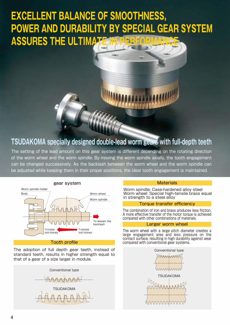
EXCELLENT BALANCE OF SMOOTHNESS, POWER AND DURABILITY BY SPECIAL GEAR SYSTEM ASSURES THE ULTIMATE IN PERFORMANCE
TSUDAKOMA specially designed double-lead worm gears with full-depth teeth The setting of the lead amount on this gear system is different depending on the rotating direction
of the worm wheel and the worm spindle. By moving the worm spindle axially, the tooth engagement
can be changed successively. As the backlash between the worm wheel and the worm spindle can
be adjusted while keeping them in their proper positions, the ideal tooth engagement is maintained.
The adoption of full depth gear teeth, instead of standard teeth, results in higher strength equal to that of a gear of a size larger in module.
Tooth profile
Worm spindle: Case-hardened alloy steel Worm wheel: Special high-tensile brass equal in strength to a steel alloy
Materials
The combination of iron and brass produces less friction. A more effective transfer of the motor torque is achieved compared with other combinations of materials.
Torque transfer efficiency
To increase tooth thickness
To decrease tooth thickness
To lessen the backlash
Worm spindle holder
Body
Worm spindle
Worm wheel
gear system
The worm wheel with a large pitch diameter creates a large engagement area and less pressure on the contact surface, resulting in high durability against wear compared with conventional gear systems.
Larger worm wheel
Conventional type
TSUDAKOMA
Conventional type
TSUDAKOMA
4
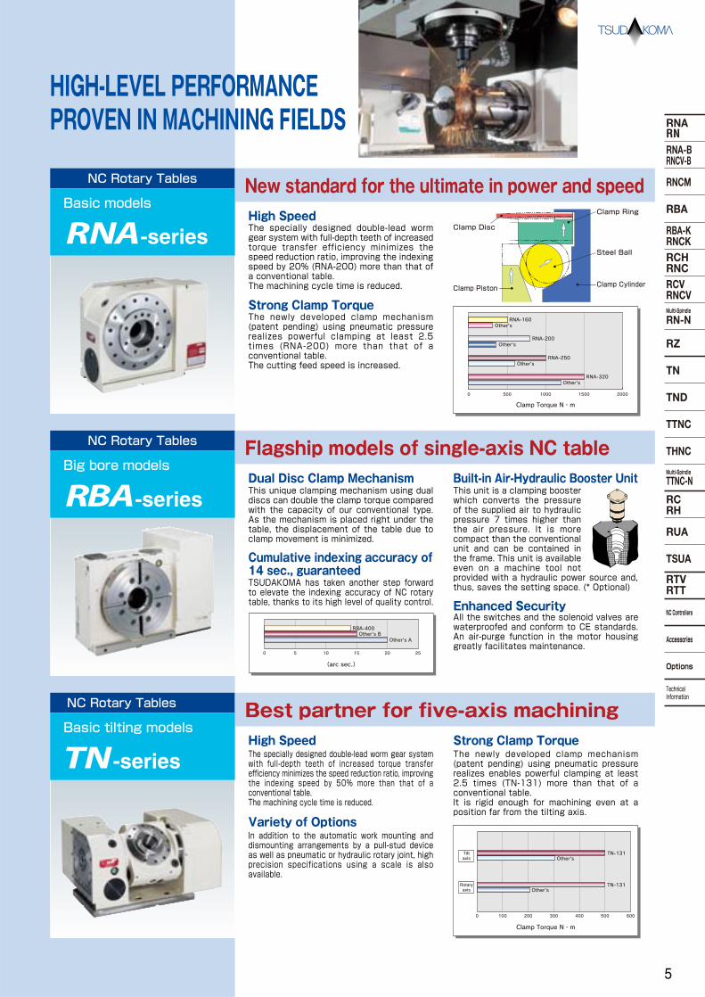
HIGH-LEVEL PERFORMANCE PROVEN IN MACHINING FIELDS
NC Rotary Tables
Basic modelsNew standard for the ultimate in power and speedHigh SpeedThe specially designed double-lead worm gear system with full-depth teeth of increased torque transfer efficiency minimizes the speed reduction ratio, improving the indexing speed by 20% (RNA-200) more than that of a conventional table. The machining cycle time is reduced.
Strong Clamp TorqueThe newly developed clamp mechanism (patent pending) using pneumatic pressure realizes powerful clamping at least 2.5 times (RNA-200) more than that of a conventional table. The cutting feed speed is increased.
High Speed Strong Clamp TorqueThe specially designed double-lead worm gear system with full-depth teeth of increased torque transfer efficiency minimizes the speed reduction ratio, improving the indexing speed by 50% more than that of a conventional table. The machining cycle time is reduced.
Variety of OptionsIn addition to the automatic work mounting and dismounting arrangements by a pull-stud device as well as pneumatic or hydraulic rotary joint, high precision specifications using a scale is also available.
The newly developed clamp mechanism (patent pending) using pneumatic pressure realizes enables powerful clamping at least 2.5 times (TN-131) more than that of a conventional table. It is rigid enough for machining even at a position far from the tilting axis.
NC Rotary Tables
Big bore modelsFlagship models of single-axis NC tableDual Disc Clamp Mechanism Built-in Air-Hydraulic Booster UnitThis unique clamping mechanism using dual discs can double the clamp torque compared with the capacity of our conventional type. As the mechanism is placed right under the table, the displacement of the table due to clamp movement is minimized.
Enhanced SecurityAll the switches and the solenoid valves are waterproofed and conform to CE standards. An air-purge function in the motor housing greatly facilitates maintenance.
Cumulative indexing accuracy of 14 sec., guaranteedTSUDAKOMA has taken another step forward to elevate the indexing accuracy of NC rotary table, thanks to its high level of quality control.
NC Rotary Tables
Basic tilting modelsBest partner for five-axis machining
This unit is a clamping booster which converts the pressure of the supplied air to hydraulic pressure 7 times higher than the air pressure. It is more compact than the conventional unit and can be contained in the frame. This unit is available even on a machine tool not provided with a hydraulic power source and, thus, saves the setting space. (* Optional)
-series
-series
-series
0 500 1000 1500 2000
Clamp Torque N・m
RNA-160
RNA-200
RNA-250
RNA-320
Other's
Other's
Other's
Other's
(arc sec.)
Other's BOther's A
0 5 10 15 20 25
RBA-400
Clamp Torque N・m
Other's
Other'sTN-131
0 100 200 300 400 500 600
TN-131
Rotary axis
Tilt axis
Clamp Ring
Clamp Disc
Clamp Piston
Steel Ball
Clamp Cylinder
5
RNARNRNA-BRNCV-B
RNCM
RBA
RBA-KRNCKRCHRNCRCVRNCVMulti-Spindle
RN-N
RZ
TND
TTNC
THNC
Multi-Spindle
TTNC-N
RCRH
RUA
TSUA
RTVRTT
NC Controllers
Accessories
Options
Technical Information
TN
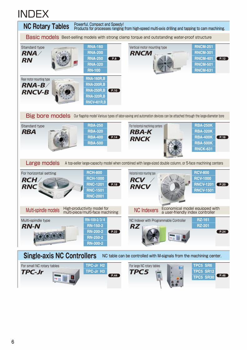
INDEXNC Rotary Tables Powerful, Compact and Speedy!
Products for processes ranging from high-speed multi-axis drilling and tapping to cam machining.
P.8
RNA-160RNA-200RNA-250RNA-320RN-100
Standard type
P.10
RNA-160R,BRNA-200R,BRNA-250R,BRNA-320R,BRNCV-401R,B
Rear motor mounting type
Basic models Best-selling models with strong clamp torque and outstanding water-proof structure
P.16
RBA-320K
RBA-500KRNCK-631
For horizontal machining centers
P.14
Standard type
Big bore models Our flagship model Various types of labor-saving and automation devices can be attached through the large-diameter bore
P.20
RCV-800RCV-1000RNCV-1201RNCV-1501
Horizontal motor mounting type
P.18
RCH-800RCH-1000RNC-1201RNC-1501RNC-2001
For horizontal setting
Large models A top-seller large-capacity model when combined with large-sized double column, or 5-face machining centers
P.12
RNCM-251RNCM-301RNCM-401RNCM-501RNCM-631
Vertical motor mounting type
Single-axis NC Controllers NC table can be controlled with M-signals from the machining center.
RBA-250K
RBA-400KRBA-320
RBA-500
RBA-250
RBA-400
P.46
TPC5 SR6TPC5 SR12TPC5 SR30
For large NC rotary tables
P.44
TPC-Jr H2TPC-Jr H3
For small NC rotary tables
/
/
/
/
P.22
RN-100-2/3/4RN-150-2RN-200-2RN-250-2RN-300-2
Multi-spindle type
Multi-spindle models High-productivity model for multi-piece/multi-face machining
P.24
RZ-161RZ-201
NC Indexer with Programmable Controller
NC Indexers Economical model equipped with a user-friendly index controller
6

DD Table・Special NC Rotary Table
NC Rotary Tables developed for specific machines Special model built in a flexible transfer line for automobile parts machining.
RC-250RC-300RC-400RC-500
P.43
RTV-304RTV-404RTV-504RTV-801
Highly rigid models with a super big bore
P.42
DD Table
RH-400RH-500RH-600
Horizontal setting type with rotary joint
P.36
For horizontal setting
RTV-202φ500 Table RTT-112
P.36
RUA-250RUA-320RUA-400RUA-500
TSUA-170TSUA-210TSUA-255TSUA-310
For vertical setting
P.40
Support spindles
P.38
Jig
Work
Accessories P.56 P.62
ChuckScroll chuck Manual tailstock Hydraulic tailstock
Power chuck
Tailstock
Support spindle Face plate
Optional SpecificationsRotary encoders and MP scales for high precision
Pull-stud Rotary joint
Pallet clamp Air-hydraulic Booster
NC Tilting Rotary Tables Machining of aluminum components for automobiles electronic devices and blades for jet engines.
P.32
THNC-251THNC-301
Manual Tilting type
P.26
TN-101TN-131TN-161
TN-201TN-320TN-450
Standard type
P.30
TTNC-631TTNC-1001
Standard type
Basic models High speed indexing and strong clamp torque for five-axis machining
P.34
TTNC-102-2TTNC-101-4TTNC-151-2TTNC-201-2
Multi-spindle type
Multi-spindle models Multi-work processing model for high productivity
TTNC-1500
TND-200 P.28
Trunnion type TND-130TND-160
・
7
RNARNRNA-BRNCV-B
RNCM
RBA
RBA-KRNCKRCHRNCRCVRNCVMulti-Spindle
RN-N
RZ
TND
TTNC
THNC
Multi-Spindle
TTNC-N
RCRH
RUA
TSUA
RTVRTT
NC Controllers
Accessories
Options
Technical Information
TN

RNA-160 RNA-200 RNA-250 RNA-320 RN-100
φ160 or 200 (Option)
φ100
135
φ55H7×45
12H8
φ40
14h7
0.09 0.09 0.17 0.41 0.52
αiF2 αiF4
38 44
1/72
41.6
25
Pneumatic
500
206
100 (200)
200
0.64
φ200 or 250 (Option)
φ120
160
φ65H7×45
12H8
φ45
18h7
αiF4
61
1/72
41.6
20
Pneumatic
800
288
125 (250)
250
1.25
φ250 (Option)
φ140
160
φ80H7×45
12H8
φ50
18h7
αiF8
80
1/90
33.3
20
Pneumatic
1000
596
125 (250)
250
1.95
φ320 (Option)
φ180
210
φ115H7×45
14H8
φ85
18h7
αiF8
150
1/120
25
20
Pneumatic
1500
939
175 (350)
350
10,800 14,400 14,400 24,800
500 800 1,000 1,500
780 1,900 1,900 4,700
4.48
φ135 (Option)
φ80
110
φ50H7×45
10H8
φ30
14h7
αiF2
0.23
28
1/36
83.3
45
Pneumatic
80
176
25 (50)
50
0.10
Nose diameter
R
L
Through-bore
Table diameter *1
Spindle diameter
○
○
○
○
○
○
○
○
○
○ Handedness
Center height
Center bore
Table T-slot width *1
Guide block width
Servo motors (for FUNAC)
Inertia converted into motor shaft
Net weight
Speed reduction ratio
Table max. rpm
Indexing accuracy(the sum)
4 4 4 4 4
Clamp system
Clamp torque
/pneumatic pressure 0.49MPa
Strength of worm gears
*2 High speed models are available. Ask us for further information. RNA-250: 320(speed reduction ratio: 1:45) RNA-320: αiF12 or an equivalent motor should be used.
min-1
N・m
(Motor rpm: 3,000min-1)
kg
sec
N・m
Allowable work weight
Allowable load (when table is clamped)
Allowable work inertia
Vertical setting kg
FN
F×LN・m
F×LN・m
kg・m2J= W・D
2
8
( ):with tailstock
Standard type
NC Rotary TablesBasic model
×10-3kg・m2
W
Horizontal setting
kg
F
F
L
F
L
φD
W
The RNA series, an improvement on the best-sel l ing RN series, has remarkably improved cost efficiency due to its high-speed operation for use in drill and tapping machines.
W
5,880
80
156
RNA-250R
*1 The tolerance of the table T-slot width is applicable to four standard slots arranged crosswise. Dimensions P.61
*2 *2
Servo motors of other manufacturers P.67
Unit: mmSpecifications
Repeatability arc sec
When assembling a faceplate or a fixture with the main spindle P.77
RNA-160・200・250・320
RN-100
8
RNARNRNA-BRNCV-B
RNCM
RBA
RBA-KRNCKRCHRNCRCVRNCVMulti-Spindle
RN-N
RZ
TN
TND
TTNC
THNC
Multi-Spindle
TTNC-N
RCRH
RUA
TSUA
RTVRTT
NC Controllers
Accessories
Options
Technical Information

RNA-160R
RNA-200R
RNA-250R
RNA-320R
RN-100R
RNA-160RNA-200RNA-250RNA-320RN-100
T-slot width
RNA-160R
RNA-200R
RNA-250R
RNA-320R
RN-100R
T-slot pitchType Q’ty
14- - 2
18- - 2
1850~100Ⅰ 4
A
-
-
25
30
-
-
12
15
-
-
80
90
-
-
12
16
-
-
33
31
-
-
35
43
-
-
22
25
17
21
21
21
8
11
11
11
60
65
65
70
-
-
40
46
23
28
28
28
12
16
16
16
B C D E F G H I J K L M
1850~132Ⅰ 4
- - - - - - - 17 8 55 - 23 1214- - 2
Note 1: When using a machine with a T-slot pitch other than the above, use suitable clamping blocks and bolts that are available on the market, or order custom-made ones from TSUDAKOMA. (Optional) Note 2: Clamping blocks are not included with the RNA-160 and RNA-200 and RN-100.
Note: The above dimensions are for FANUC servo motors. The dimensions of servo motors of other manufacturers may be larger.
Clamping block and bolt
HG
IJ
φM
□L D FE
KC
BA
TypeⅠ
※When αiF2 is used
Unit: mm
Unit: mm
Dimensions
25
φM
H
JI
L
φ100h7
1487
170
220
135
25
85 285370
90 195
φ120h7
158
180
7
270
160
115315
420105
200
1587
φ140h7
179
285
160
120 25375
495120
230
370
210
155 25410
565155
230 2037
φ180h7
224
45 149209 1
15
φ115H7
15 φ85
8-M6 Depth 10(Divided equally PCD68)
4-M5 Depth 8(Divided equally PCD68)
φ6H7 Depth 1045° 22.5°
145
15
φ50H7
φ30
45
φ80h7
145
199
178
180
110
3706060
30070
φ55H7
φ40
45 94154 1
15
15
φ65H7
15
45 104164 1
15
φ45
45 104164 1
15
φ80H7
15
φ50
2525
30
20
45° 6-M10 Depth 20φ10H7 Depth 12
45° 6-M10 Depth 20φ10H7 Depth 12
22.5°
(PCD110)
8-M10 Depth 20 (Divided equally) φ10H7 Depth 15
22.5°
(PCD140)
8-M12 Depth 24 (Divided equally) φ10H7 Depth 15
6 points out of 8 equally divided sections: PCD75( )
( ) 6 points out of 8 equally divided sections: PCD90
9
RNARNRNA-BRNCV-B
RNCM
RBA
RBA-KRNCKRCHRNCRCVRNCVMulti-Spindle
RN-N
RZ
TND
TTNC
THNC
Multi-Spindle
TTNC-N
RCRH
RUA
TSUA
RTVRTT
NC Controllers
Accessories
Options
Technical Information
TN
Unit: mm
RNA-160R,B
φ160 or 200 (Option)
φ100
135
φ55H7×45 φ65H7×45 φ80H7×45 φ115H7×45
12H8
φ40
14h7
αiF4
0.56
56
αiF2
0.56
53
1/72
41.6
25
Pneumatic
500
206
100 (200)
10,800
500
780
0.64
RNA-200R,B
φ200 or 250 (Option)
φ120
160
12H8
φ45
18h7
αiF4
0.64
77
1/72
41.6
20
Pneumatic
800
288
125 (250)
14,400
800
1,900
1.25
RNA-250R,B
φ250 (Option)
φ320 (Option)
φ400
φ140
160
12H8
φ50
18h7
αiF8
0.97
95
1/90
33.3
20
Pneumatic
1000
596
125 (250)
14,400
1,000
1,900
1.95
RNA-320R,B
φ180
210
14H8
φ85
18h7
αiF8
0.84
165
1/120
25
20
Pneumatic
1500
939
175 (350)
24,800
1,500
4,700
4.48
RNCV-401R,B
ー
255
φ40H7×21
18H7
φ40
18h7
αiF12
4.01
330
1/180
11.1
15
Hydraulic or Air-hydraulic (optional)
1,764 (Hydraulic pressure 3.5Mpa)
1,666
200 (500)
39,200
1,764
2,450
9.7
ー ー ー ー ー
○ ○ ○ ○ ○
kg
FN
F×LN・m
F×LN・m
kg・m2J= W・D
2
8
Specifications
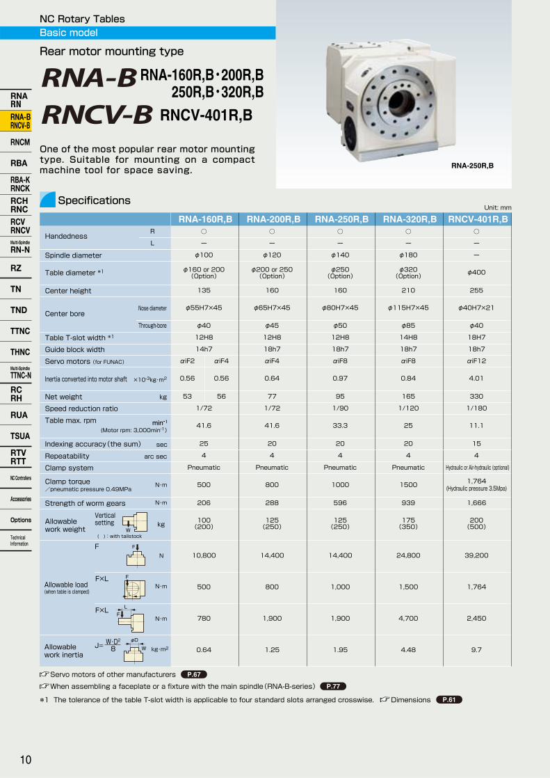
Rear motor mounting type
RNA-250R,B
W
F
F
L
F
L
φD
W
One of the most popular rear motor mounting type. Suitable for mounting on a compact machine tool for space saving.
NC Rotary TablesBasic model
Nose diameter
R
L
Through-bore
Table diameter *1
Spindle diameter
Handedness
Center height
Center bore
Table T-slot width *1
Guide block width
Servo motors (for FUNAC)
Net weight
Speed reduction ratio
Table max. rpm
Indexing accuracy(the sum)
4 4 4 4 4
Clamp system
Clamp torque
/pneumatic pressure 0.49MPa
Strength of worm gears
min-1
N・m
(Motor rpm: 3,000min-1)
kg
sec
N・m
Allowable work weight
Allowable load (when table is clamped)
Allowable work inertia
Vertical setting
( ):with tailstock
Servo motors of other manufacturers P.67
*1 The tolerance of the table T-slot width is applicable to four standard slots arranged crosswise. Dimensions P.61
Inertia converted into motor shaft ×10-3kg・m2
Repeatability arc sec
When assembling a faceplate or a fixture with the main spindle(RNA-B-series) P.77
RNA-160R,B・200R,B 250R,B・320R,B
RNCV-401R,B
10
RNARNRNA-BRNCV-B
RNCM
RBA
RBA-KRNCKRCHRNCRCVRNCVMulti-Spindle
RN-N
RZ
TN
TND
TTNC
THNC
Multi-Spindle
TTNC-N
RCRH
RUA
TSUA
RTVRTT
NC Controllers
Accessories
Options
Technical Information

With Support Spindle and Fixture Plate
P.60
RNA-160R,BRNA-200R,BRNA-250R,BRNA-320R,BRNCV-401R,B
RNA-160R,BUnit: mm
Unit: mm
Dimensions
RNA-200R,B
RNA-250R,B
RNA-320R,B
RNCV-401R,B
14- - 2
18- - 2
1850~100Ⅰ 4
A
-
-
25
30
-
-
12
15
-
-
80
90
-
-
12
16
-
-
33
31
-
-
35
43
-
-
22
25
17
21
21
21
8
11
11
11
60
65
65
70
-
-
40
46
23
28
28
28
12
16
16
16
B C D E F G H I J K L M
1850~132Ⅰ 4
30 15 90 16 31 43 25 21 11 70 46 28 161855~155Ⅰ 4
Note: The above dimensions are for FANUC servo motors. The dimensions of servo motors of other manufacturers may be larger.
RNA-250R,B
RNA-250R,B
RNCV-401R,B
Clamping block and bolt
21521 30164
φ50
φ41
φ40H7
310
530
215
φ400
5
RT-22
Work: cutting tools, Automobile engine parts
HG
IJ
φM
□L D FE
KC
BA
TypeⅠ
45° 6-M10 Depth 20φ10H7 Depth 12
1094515
φ55H7 φ40
333
7 148
φ100h7
45° φ10H7 Depth 12
45 11915
φ65H7 φ45
343
1587
φ120h7
22.5° φ10H7 Depth 15
1194515
φ80H7 φ50
1587
346
φ140h7
22.5° φ10H7 Depth 15
1644515
φ115H7 φ85
7
391
203
φ180h7
※When αiF2 is used
Note 1: When using a machine with a T-slot pitch other than the above, use suitable clamping blocks and bolts that are available on the market, or order custom-made ones from TSUDAKOMA. (Optional) Note 2: Clamping blocks are not included wit the RNA-160R,B and RNA-200R,B.
6 points out of 8 equally divided sections: PCD75( )
6-M10 Depth 206 points out of 8 equally divided sections: PCD90( )
(Divided equally PCD110)8-M10 Depth 20
(Divided equally PCD140)8-M12 Depth 24
Type Q’ty
Two-axis machining system by combining two NC rotary tables with a hydraulic tailstock.
T-slot widthT-slot pitch
25
φM
H
JI
L
465
255
337245
582225210
30
286
220
150
8523590
135
25
310
160270
175
105 115280
25
120 120305
309
160285
185
25
220
375155 155
370
210
30
RNARNRNA-BRNCV-B
RNCM
RBA
RBA-KRNCKRCHRNCRCVRNCVMulti-Spindle
RN-N
RZ
TND
TTNC
THNC
Multi-Spindle
TTNC-N
RCRH
RUA
TSUA
RTVRTT
NC Controllers
Accessories
Options
Technical Information
TN
11
Unit: mm
RNCM-251 RNCM-301○
○
φ250
160
φ40H7
φ32
12H7
18h7
αiF4 or αiF8
0.30 【3.01】
75
1/180
11.1
15
4
Hydraulic or air-hydraulic (optional)
490 【50】 274
【28】
470【48】
100 (250)
250
19,600 【2,000】
490 【50】
931 【95】
1.2 【12.3】
○
○
φ320
210
φ40H7
φ40
14H7
18h7
αiF8 αiF12
0.34 【3.43】
1.76 【17.9】
200
1/360
5.5
1/180
11.1
15
4
Hydraulic or air-hydraulic (optional)
833 【85】
764【78】
150 (350)
350
29,400 【3,000】
833 【85】
1,568 【160】
3.7 【38.5】
RNCM-401○
○
φ400
255
φ40H7
φ40
14H7
18h7
αiF12
2.05 【20.9】
300
1/180
11.1
15
4
Hydraulic or air-hydraulic (optional)
1,764 【180】
1,666【170】
200 (500)
500
39,200 【4,000】
1,764 【180】
2,450 【250】
9.7 【99.8】
RNCM-501○
○
φ500
310
φ50H7
φ50
18H7
18h7
αiF12
3.09 【31.9】
450
1/180
11.1
15
4
Hydraulic or air-hydraulic (optional)
2,450 【250】
2,450【250】
250 (600)
600
49,000 【5,000】
2,450 【250】
3,430 【350】
18.2 【185.2】
RNCM-631○
○
φ630
400
φ60H6
φ60
18H7
18h7
αiF12
5.55 【56.6】
800
1/180
11.1
15
4
Hydraulic or air-hydraulic (optional)
4,410 【450】
4,116【420】
400 (1,000)
1,000
49,000 【5,000】
4,410 【450】
7,840 【800】
49.6 【506.2】
R
L
Nose diameter
Handedness
Table diameter
Center height
Center bore
Repeatability
*2 For model RNCM-631, a big bore type is also available. (center bore: φ180H7)
min-1
N・m 【kgf・m】
kg
arc sec
N・m 【kgf・m】
kg
kg
FN
【kgf】
F×LN・m
【kgf・m】
F×LN・m
【kgf・m】
kg・m2 【kgf・cm・ sec2】
J= W・D2
8
Specifications
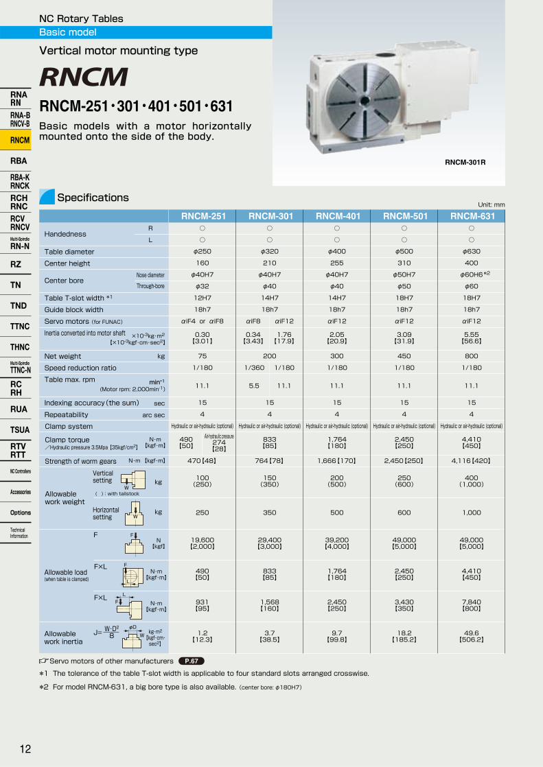
Vertical motor mounting type
×10-3kg・m2
【×10-3kgf・cm・sec2】
W
W
F
F
L
F
L
φD
W
RNCM-301R
Basic models with a motor horizontally mounted onto the side of the body.
Air-hydraulic pressure
*2
NC Rotary TablesBasic model
Through-bore
Table T-slot width *1
Guide block width
Servo motors (for FUNAC)
Inertia converted into motor shaft
Net weight
Speed reduction ratio
Table max. rpm
Indexing accuracy(the sum)
(Motor rpm: 2,000min-1)
sec
Clamp system
Clamp torque
/Hydraulic pressure 3.5Mpa 【35kgf/cm2】
Strength of worm gears
Allowable work weight
Allowable load (when table is clamped)
Allowable work inertia
Vertical setting
( ):with tailstock
Horizontal setting
*1 The tolerance of the table T-slot width is applicable to four standard slots arranged crosswise.
Servo motors of other manufacturers P.67
RNCM-251・301・401・501・631
12
RNARNRNA-BRNCV-B
RNCM
RBA
RBA-KRNCKRCHRNCRCVRNCVMulti-Spindle
RN-N
RZ
TN
TND
TTNC
THNC
Multi-Spindle
TTNC-N
RCRH
RUA
TSUA
RTVRTT
NC Controllers
Accessories
Options
Technical Information

RNARNRNA-BRNCV-B
RNCM
RBA
RBA-KRNCKRCHRNCRCVRNCVMulti-Spindle
RN-N
RZ
TND
TTNC
THNC
Multi-Spindle
TTNC-N
RCRH
RUA
TSUA
RTVRTT
NC Controllers
Accessories
Options
Technical Information
TN
RNCM-251R
Dimensions
RNCM-301R
RNCM-401R
RNCM-501R
RNCM-631R
Note: The above dimensions are for FANUC servo motors. The dimensions of servo motors of other manufacturers may be larger.
Unit: mm
C
FD E
HG J
I
K
B
φM
□L
A
TypeⅡ
RNCM-251RNCM-301RNCM-401RNCM-501RNCM-631
Unit: mm
18Ⅰ 4
18Ⅰ 4
1855~155
55~127
50~125
Ⅰ 4
A
25
30
30
40
12
15
15
20
80
90
90
110
12
16
16
18
33
31
31
42
35
43
43
50
22
25
25
25
21
21
21
21
11
11
11
11
65
70
70
70
40
46
46
46
28
28
28
28
16
16
16
16
B C D E F G H I J K L M
1860~194Ⅰ 4
40 18 63 18 15 30 58 21 11 105 60 28 161890~255Ⅱ 4
Note: When using a machine with a T-slot pitch other than the above, use suitable clamping blocks and bolts that are available on the market, or order custom-made ones from TSUDAKOMA. (Optional)
Clamping block and bolt
1642012420
φ45
φ32
φ40H7
390
402
567210145
305
160
1605
φ250
3013920
φ50
φ42
φ40H7
287
2155
φ320
415
710185185
505
380
210
3016421
φ50
φ41
φ40H7
2455
302
φ400
546
469
789225225
465
255
2519832
φ50
φ52
φ50H7
327
2955
φ500
575
597
877270260
565
310
With Hydraulic Power Chuck
P.57
With Support Spindle and Fixture Plate
RNCM-301R
RNCM-501R
HG
IJ
φM
□L D FE
KC
BA
TypeⅠ
P.60
6519565
φ250
φ210
φ70
φ60H6
3205
φ630
665
1035350350
775
400
φ181
Type Q’ty T-slot widthT-slot pitch
13

Unit: mm
RBA-320 RBA-500○
○
φ250
160
φ95H7
φ71
12H7
18h7
αiF8
0.94 【9.58】
100
1/90
22.2
14
4
Hydraulic or air-hydraulic (optional)
1,000 【102】
581【59】
150 (300)
300
19,600 【2,000】
1,000 【102】
980 【100】
2.34 【23.8】
○
○
φ320
210
φ130H7
φ101
14H7
18h7
αiF12
3.04 【31.0】
180
1/120
16.6
14
4
Hydraulic or air-hydraulic (optional)
2,450 【250】
939【96】
200 (400)
400
29,400 【3,000】
2,450 【250】
3,626 【370】
5.12 【52.2】
○
○
φ400
255
φ190H7
φ151
14H7
18h7
αiF12
3.63 【37.0】
300
1/120
16.6
14
4
Hydraulic or air-hydraulic (optional)
4,200 【428】
1,666【170】
250 (500)
500
39,200 【4,000】
4,200 【428】
5,880 【600】
9.7 【98.9】
○
○
φ500
310
φ220H7
φ182
18H7
18h7
αiF12
3.05 【31.1】
550
1/180
11.1
14
4
Hydraulic or air-hydraulic (optional)
6,100 【600】
3,276【334】
250 (600)
600
49,000 【5,000】
6,100 【622】
13,132 【1,340】
18.2 【185.2】
Specifications
Standard type
Big bore model
W
W
F
F
L
F
L
φD
W
For tables with a diameter of 630 or more, please order a big bore type of the following models:
φ630
φ800
φ1000
Tables diameter Model Center bore
RNCM-631 φ180H7
RNCV-801 φ250H7
RNCV-1001 φ300H7
Specifications
P.12
P.20
P.20
Our flagship models equipped with state-of-the-art Tsudakoma technology. Various types of labor-saving and automation devices can be attached through the large through-bore.
NC Rotary Tables
R
L
Nose diameter
Handedness
Table diameter
Center height
Center bore
Repeatability
min-1
N・m 【kgf・m】
kg
arc sec
N・m 【kgf・m】
kg
kg
FN
【kgf】
F×LN・m
【kgf・m】
F×LN・m
【kgf・m】
kg・m2 【kgf・cm・ sec2】
J= W・D2
8
×10-3kg・m2
【×10-3kgf・cm・sec2】
Through-bore
Table T-slot width *1
Guide block width
Servo motors (for FUNAC)
Inertia converted into motor shaft
Net weight
Speed reduction ratio
Table max. rpm
Indexing accuracy(the sum)
(Motor rpm: 2,000min-1)
sec
Clamp system
Clamp torque
/Hydraulic pressure 3.5Mpa 【35kgf/cm2】
Strength of worm gears
Allowable work weight
Allowable load (when table is clamped)
Allowable work inertia
Vertical setting
( ):with tailstock
Horizontal setting
Servo motors of other manufacturers P.67
*1 The tolerance of the table T-slot width is applicable to four standard slots arranged crosswise.
RBA-250 RBA-400
RBA-250R
RBA-250・320・400・500
14
RNARNRNA-BRNCV-B
RNCM
RBA
RBA-KRNCKRCHRNCRCVRNCVMulti-Spindle
RN-N
RZ
TN
TND
TTNC
THNC
Multi-Spindle
TTNC-N
RCRH
RUA
TSUA
RTVRTT
NC Controllers
Accessories
Options
Technical Information

RNARNRNA-BRNCV-B
RNCM
RBA
RBA-KRNCKRCHRNCRCVRNCVMulti-Spindle
RN-N
RZ
TND
TTNC
THNC
Multi-Spindle
TTNC-N
RCRH
RUA
TSUA
RTVRTT
NC Controllers
Accessories
Options
Technical Information
TN
With #50 Pull Stud Unit
P.64
RBA-400R
Dimensions
RBA-320R
RBA-500R
φ250
10 170
245
305
160
352
418
583145156
φ150
φ75
φ95H7
2215
180
23
φ71
φ320
303
22020
386
395
210
502
696
185185
φ175
φ115
φ130H7
240
411522φ101
335
10
φ400
465
557
782
225216
474
255
φ225
φ165
275
462322
φ190H7
φ151
265
371
30520
φ500
565
574
310
608
873
270256
1850~125Ⅰ 4
1873~162Ⅰ 4
1873~193Ⅰ 4
A
25
30
30
40
12
15
15
20
80
90
90
110
12
16
16
18
33
31
31
42
35
43
43
50
22
25
25
25
21
21
21
21
11
11
11
11
65
70
70
70
40
46
46
46
28
28
28
28
16
16
16
16
B C D E F G H I J K L M
1873~233Ⅰ 4
Note: The above dimensions are for FANUC servo motors. The dimensions of servo motors of other manufacturers may be larger.
With Support Spindle and Fixture Plate
P.60
RBA-320R
Clamping block and bolt
Unit: mm
Unit: mm
HG
IJ
φM
□L D FE
KC
BA
TypeⅠ
Type Q’ty
Note: When using a machine with a T-slot pitch other than the above, use suitable clamping blocks and bolts that are available on the market, or order custom-made ones from TSUDAKOMA. (Optional)
T-slot widthT-slot pitch
RBA-250R
RBA-400R
RBA-250R
φ255
φ195
325
592530
φ220H7
φ182
RBA-250RBA-320RBA-400RBA-500
15

For tables with a diameter of 800 or more, please order a big bore type of the following models:
Note: For the RNCK-631, a basic model (for vertical machining centers) is also available. (for standard bore)
For horizontal machining centers
RBA-320K
φ800
φ1000
Tables diameter Model Center bore
RNCV-801 φ250H7(Upper class motor) (Upper class motor) RNCV-1001 φ300H7
SpecificationsP.20
P.20
Another flagship model with highest-class specifications exclusively for horizontal machining centers. A popular model for the aircraft , automobi le , and cutt ing tool industries. Various types of labor-saving and automation devices can be attached through the large through-bore.
Unit: mm
φ250
160
φ95H7
12H7
φ71
18h7
αiF8
0.94 【9.58】
105
1/90
22.2
14
4
Hydraulic or air-hydraulic (optional)
1.000 【102】
581【59】
150 (300)
19,600 【2,000】
1,000 【102】
980 【100】
2.34 【23.8】
RBA-320Kφ320
210
φ130H7
14H7
φ101
18h7
αiF12
3.04 【31.0】
185
1/120
16.6
14
4
Hydraulic or air-hydraulic (optional)
2,450 【250】
939【96】
200 (400)
29,400 【3,000】
2,450 【250】
3,626 【370】
5.12 【52.2】
φ400
255
φ190H7
14H7
φ151
18h7
αiF12
3.63 【37.0】
300
1/120
16.6
14
4
Hydraulic or air-hydraulic (optional)
4,200 【428】
1,666【170】
250 (500)
39,200 【4,000】
4,200 【428】
5,880 【600】
9.7 【98.9】
RBA-500Kφ500
310
φ220H7
18H7
φ182
18h7
αiF12
3.00 【30.6】
550
1/180
11.1
14
4
Hydraulic or air-hydraulic (optional)
6,100 【622】
3,276【334】
250 (600)
49,000 【5,000】
6,100 【622】
13,132 【1,340】
18.2 【185.2】
Specifications
W
F
F
L
F
L
φD
W
RNCK-631φ630
400
φ180H7
18H7
φ180
18h7
αiF12
5.55 【56.6】
800
1/180
11.1
15
4
Hydraulic or air-hydraulic (optional)
4,410 【450】
4,116【420】
400 (800)
49,000 【5,000】
4,410 【450】
7,840 【800】
49.6 【506.2】
NC Rotary TablesBig bore model
Nose diameter
Table diameter
Center height
Center bore
Repeatability
min-1
N・m 【kgf・m】
kg
arc sec
N・m 【kgf・m】
kg
FN
【kgf】
F×LN・m
【kgf・m】
F×LN・m
【kgf・m】
kg・m2 【kgf・cm・ sec2】
J= W・D2
8
×10-3kg・m2
【×10-3kgf・cm・sec2】
Through-bore
Table T-slot width *1
Guide block width
Servo motors (for FUNAC)
Inertia converted into motor shaft
Net weight
Speed reduction ratio
Table max. rpm
Indexing accuracy(the sum)
(Motor rpm: 2,000min-1)
sec
Clamp system
Clamp torque
/Hydraulic pressure 3.5Mpa【35kgf/cm2】
Strength of worm gears
Allowable work weight
Allowable load (when table is clamped)
Allowable work inertia
Vertical setting
( ):with tailstock
Servo motors of other manufacturers P.67
*1 The tolerance of the table T-slot width is applicable to four standard slots arranged crosswise.
RBA-250K RBA-400K
RBA-250K・320K・400K・500K
RNCK-631
16
RNARNRNA-BRNCV-B
RNCM
RBA
RBA-KRNCKRCHRNCRCVRNCVMulti-Spindle
RN-N
RZ
TN
TND
TTNC
THNC
Multi-Spindle
TTNC-N
RCRH
RUA
TSUA
RTVRTT
NC Controllers
Accessories
Options
Technical Information

RNARNRNA-BRNCV-B
RNCM
RBA
RBA-KRNCKRCHRNCRCVRNCVMulti-Spindle
RN-N
RZ
TND
TTNC
THNC
Multi-Spindle
TTNC-N
RCRH
RUA
TSUA
RTVRTT
NC Controllers
Accessories
Options
Technical Information
TN
For Twin-spindle Machining on Both-side Face Plates
Dimensions
RBA-320K
RBA-500K
RNCK-631
1850~125Ⅰ 4
1873~162Ⅰ 4
1873~160Ⅰ 4
A
25
30
30
40
12
15
15
20
80
90
90
110
12
16
16
18
33
31
31
42
35
43
43
50
22
25
25
25
21
21
21
21
11
11
11
11
65
70
70
70
40
46
46
46
28
28
28
28
16
16
16
16
B C D E F G H I J K L M
1873~200Ⅰ 4
40 18 63 18 15 30 58 21 11 105 60 28 1618100~255Ⅱ 4
Note: The above dimensions are for FANUC servo motors. The dimensions of servo motors of other manufacturers may be larger.
With Rotary Joint P.64
RT-147
Clamping block and bolt
Unit: mm
Unit: mm
253
φ250
17010149150
572
160
303
22020
φ320
709
210
198185
10 265
φ400
808
255
220225
335
20 305
φ500
916
310
260264
374
A swivel-type connector box (optional) is useful to prevent motor cables and connectors from being entangled because of the rotation of the machine pallet.
RBA-320K
6519565
φ250
φ210
φ70
φ60H6
φ181
455
3205
φ630
720
350350
975
400
C
FD E
HG J
I
K
B
φM
□L
A
TypeⅡ
HG
IJ
φM
□L D FE
KC
BA
TypeⅠ ※For standard bore
φ150
φ75
φ95H7
2215
180
23
φ71
φ175
φ115
φ130H7
240
411522
φ101
φ225
φ165
275
462322
φ190H7
φ151
Type Q’ty
Note: When using a machine with a T-slot pitch other than the above, use suitable clamping blocks and bolts that are available on the market, or order custom-made ones from TSUDAKOMA. (Optional)
With Swivel-type Connector Box
T-slot widthT-slot pitch
RBA-250KRBA-320KRBA-400KRBA-500KRNCK-631
RBA-250K
RBA-400K
RBA-400K
φ255
φ195
325
592530
φ220H7
φ182
17

Unit: mm
Hydraulic or air-hydraulic (optional) Hydraulic
RNC-1201φ1,250
370
φ75H7
22H7
ー
αiF22
5.2 【53.0】
3,100
1/720
2.7
15
4
Hydraulic or air-hydraulic (optional)
9,800 【1,000】
21,560【2,200】
8,000
49,000 【5,000】
9.800 【1,000】
24.500 【2,500】
2,255 【23,000】
RNC-1501φ1,500
400
φ75H7
28H7
ー
αiF22
5.6 【56.6】
3,600
1/720
2.7
15
4
Hydraulic or air-hydraulic (optional)
9,800 【1,000】
21,560【2,200】
8,000
49,000 【5,000】
9.800 【1,000】
24.500 【2,500】
2,255 【23,000】
RNC-2001φ2,000
620
φ225H7
28H7
ー
αiF30
17.2 【175.3】
8,000
1/720
2.7
15
4
Hydraulic or air-hydraulic (optional)
19,600 【2,000】
49,000【5,000】
10,000
58,800 【6,000】
19,600 【2,000】
34,300 【3,500】
4,900 【50,000】
Specifications
For horizontal setting
Large models
RNC-1201L
W
F
F
L
F
L
φD
W
Horizontal large-capacity model combined with large-sized double column, for 5-face machining centers. Has the high rigidity required for machining heavy workpieces.
NC Rotary Tables
Nose diameter
Table diameter ( ):optional
Table height
Center bore
Repeatability
min-1
N・m 【kgf・m】
kg
arc sec
N・m 【kgf・m】
kg
FN
【kgf】
F×LN・m
【kgf・m】
F×LN・m
【kgf・m】
kg・m2 【kgf・cm・ sec2】
J= W・D2
8
×10-3kg・m2
【×10-3kgf・cm・sec2】
Table T-slot width *1
Guide block width
Servo motors (for FUNAC)
Inertia converted into motor shaft
Net weight
Speed reduction ratio
Table max. rpm
Indexing accuracy(the sum)
(Motor rpm: 2,000min-1)
sec
Clamp system
Clamp torque
/Hydraulic pressure 3.5Mpa【35kgf/cm2】
Strength of worm gears
Allowable work weight
Allowable load (when table is clamped)
Allowable work inertia
Horizontal setting
Servo motors of other manufacturers P.67
*1 The tolerance of the table T-slot width is applicable to four standard slots arranged crosswise.
φ800(φ1,000)
320
φ75H7×30
18H7
22h7
αiF12
4.72 【48.2】
1,150
1/360
5.5
15
4
7,000 【714】
7,840【800】
4,000
100,000 【10,204】
7,000 【714】
11,600 【1,184】
320 【3,265】
RCH-800 RCH-1000φ1,000(φ1,200)
330
φ75H7×30
22H7
22h7
αiF22
8.24 【84.1】
1,700
1/360
5.5
15
4
20,000 【2,040】
13,230【1,350】
7,000
185,000 【18,878】
20,000 【2,040】
22,900 【2,337】
874 【8,918】
RCH-800・1000
RNC-1201・1501・2001
18
RNARNRNA-BRNCV-B
RNCM
RBA
RBA-KRNCKRCHRNCRCVRNCVMulti-Spindle
RN-N
RZ
TN
TND
TTNC
THNC
Multi-Spindle
TTNC-N
RCRH
RUA
TSUA
RTVRTT
NC Controllers
Accessories
Options
Technical Information

RNARNRNA-BRNCV-B
RNCM
RBA
RBA-KRNCKRCHRNCRCVRNCVMulti-Spindle
RN-N
RZ
TND
TTNC
THNC
Multi-Spindle
TTNC-N
RCRH
RUA
TSUA
RTVRTT
NC Controllers
Accessories
Options
Technical Information
TN
RCH-800RCH-1000RNC-1201RNC-1501
Dimensions
2280~400Ⅱ 4
2280~320Ⅱ 4~8
2280~255Ⅱ 4~8
A
40
40
50
50
20
20
20
20
85
85
74
74
24
24
20
20
20
20
18
18
41
41
36
36
60
60
70
77
27
27
27
15
13
13
13
17.5
115
115
130
120
80
80
70
70
32
32
32
41.3
20
20
20
24
B C D E F G H I J K L M
2880~255Ⅳ 4~8
Note: The above dimensions are for FANUC servo motors. The dimensions of servo motors of other manufacturers may be larger.
Clamping block and bolt
Unit: mm
Unit: mm
C
FD E
HG J
I
K
B
φM
□L
A
M
HJ
G
C
D FE
I
K
BA
□L
TypeⅡ
TypeⅣ
RNC-2001Large NC rotary table with a diameter of 2,000mm. Used for the position detecting device for controlling the posture of artificial satellites and other devices.
Indexing accuracy: ±3 sec Minimal angular indication: 0.5 sec
Type Q’ty
Note: When using a machine with a T-slot pitch other than the above, use suitable clamping blocks and bolts that are available on the market, or order custom-made ones from TSUDAKOMA. (Optional)
T-slot widthT-slot pitch
RCH-800RCH-800
454
449
920
890
1335448887
320
φ800
RCH-10001050
1133
565
565
1417902 515
330
φ1000
RNC-1201・RNC-1501
45
φ105φ75H7
370
1871
7001171
650
1580
700
700
700700
(400)
( ):RNC-1501L
φ1250(φ1500)
30
H7φ75
30
H7φ75
19

Unit: mm
RNCV-1201 RNCV-1501
Hydraulic or air-hydraulic (optional) Hydraulic
φ1,250
750
φ75H7
ー
22H7
22h7
αiF22
12.8 【130.2】
4,500
1/720
2.7
15
4
Hydraulic or air-hydraulic (optional)
17,650 【1,800】
21,560【2,200】
2,000 (5,000)
5,000
58,800 【6,000】
17,650 【1,800】
19,600 【2,000】
2,255 【23,000】
φ1,500
950
φ75H7
ー
28H7
28h7
αiF22
12.8 【130.2】
7,000
1/720
2.7
15
4
Hydraulic or air-hydraulic (optional)
17,650 【1,800】
21,560【2,200】
2,000 (5,000)
5,000
58,800 【6,000】
17,650 【1,800】
19,600 【2,000】
2,255 【23,000】
Specifications
Horizontal motor mounting type
Large models
W
W
F
F
L
F
L
φD
W
Standard model with the motor mounted horizontally onto the side of the body. The unit is also equipped with a powerful hydraulic clamping mechanism.
NC Rotary Tables
R
L
Nose diameter
Handedness
Table diameter ( ):optional
Center height
Center bore
Repeatability
min-1
N・m 【kgf・m】
kg
arc sec
N・m 【kgf・m】
kg
kg
FN
【kgf】
F×LN・m
【kgf・m】
F×LN・m
【kgf・m】
kg・m2 【kgf・cm・ sec2】
J= W・D2
8
×10-3kg・m2
【×10-3kgf・cm・sec2】
Through-bore
Table T-slot width *1
Guide block width
Servo motors (for FUNAC)
Inertia converted into motor shaft
Net weight
Speed reduction ratio
Table max. rpm
Indexing accuracy(the sum)
(Motor rpm: 2,000min-1)
sec
Clamp system
Clamp torque
/Hydraulic pressure 3.5Mpa 【35kgf/cm2】
Strength of worm gears
Allowable work weight
Allowable load (when table is clamped)
Allowable work inertia
Vertical setting
( ):with tailstock
Horizontal setting
Servo motors of other manufacturers P.67
*1 The tolerance of the table T-slot width is applicable to four standard slots arranged crosswise.
K
○
○
ー
○
○
ー
ー
ー
○
ー
ー
○
RCV-800R
RCV-800 RCV-1000
φ800(φ1,000)
530
φ360H7×45
φ310
18H7
22h7
αiF12
4.89 【49.9】
1,350
1/360
5.5
15
4
7,000 【7.4】
7,840【800】
2,000 (4,000)
4,000
100,000 【10,204】
7,000 【714】
11,600 【1,184】
320 【3,265】
φ1,000(φ1,200)
625
φ410H7×75
φ360
22H7
22h7
αiF22
8.24 【84.1】
2,500
1/360
5.5
15
4
20,000 【2,040】
13,230【1,350】
3,500 (7,000)
7,000
185,000 【18,878】
20,000 【2,040】
22,900 【2,337】
874 【8,918】
RCV-800・1000RNCV-1201・1501
20
RNARNRNA-BRNCV-B
RNCM
RBA
RBA-KRNCKRCHRNCRCVRNCVMulti-Spindle
RN-N
RZ
TN
TND
TTNC
THNC
Multi-Spindle
TTNC-N
RCRH
RUA
TSUA
RTVRTT
NC Controllers
Accessories
Options
Technical Information
RNARNRNA-BRNCV-B
RNCM
RBA
RBA-KRNCKRCHRNCRCVRNCVMulti-Spindle
RN-N
RZ
TND
TTNC
THNC
Multi-Spindle
TTNC-N
RCRH
RUA
TSUA
RTVRTT
NC Controllers
Accessories
Options
Technical Information
TN
Dimensions
Note: The above dimensions are for FANUC servo motors. The dimensions of servo motors of other manufacturers may be larger.
CT-95
Unit: mm
RNCV-1201RNCV-1501
2890~505Ⅳ 8
A
50
70
20
35
74
95
20
29
18
16
36
50
77
112
15
15
17.5
17.5
120
160
70
100
41.3
41.3
24
24
B C D E F G H I J K L M
28150~600Ⅳ 8
Clamping block and boltUnit: mm
C
FD E
HG J
I
K
B
φM
□L
A
M
HJ
G
C
D FE
I
K
BA
□L
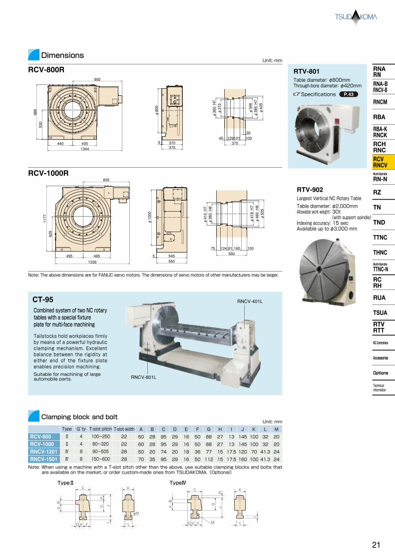
Combined system of two NC rotary tables with a special fixture plate for multi-face machining
RNCV-801L
Tailstocks hold workpieces firmly by means of a powerful hydraulic clamping mechanism. Excellent balance between the rigidity at either end of the fixture plate enables precision machining.
Suitable for machining of large automobile parts.
RNCV-401L
TypeⅡ TypeⅣ
Type Q’ty
Note: When using a machine with a T-slot pitch other than the above, use suitable clamping blocks and bolts that are available on the market, or order custom-made ones from TSUDAKOMA. (Optional)
T-slot widthT-slot pitch
RTV-902Largest Vertical NC Rotary Table
Table diameter: φ2,000mm Allowable work weight: 30t (with support spindle) Indexing accuracy: 15 sec Available up to φ3,000 mm
RTV-801Table diameter: φ800mm Through-bore diameter: φ420mm
Specifications P.43
RCV-800R892
986
530
1344435440
RCV-1000R
1336
1177
625
495495
835
RCV-800RCV-1000
22100~250Ⅱ 4
2280~320Ⅱ 4
60
60
28
28
95
95
29
29
16
16
50
50
88
88
27
27
13
13
145
145
100
100
32
32
20
20
101129375
3010045
φ360 H7
φ310
φ346
φ385 H7
φ425
3753705
φ800
5505455
φ1000
55091124 10016075
φ410 H7
φ360 H8
φ418 H7
φ460 H8
φ505
21

Unit: mm
RN-100-2/3/4
Handedness
Spindle diameter
Table diameter Center height
Center bore
Minimum distance between table centers
Table T-slot width *1
Guide block width
Servo motors (for FUNAC)
Number of axis
Inertia converted into motor shaft(When spindle pitch is minimum)
Speed reduction ratio
Table max. rpm
Indexing accuracy(the sum)
Clamp system
Clamp torque
Strength of worm gears
min-1 (Motor rpm: 2,000min-1)
Net weight kg
sec
N・m 【kgf・m】
kg
kg
FN
【kgf】
F×LN・m
【kgf・m】
F×LN・m
【kgf・m】
kg・m2 【kgf・cm・ sec2】
J= W・D2
8
Specifications
Multi-spindle models
×10-3kg・m2
【×10-3kgf・cm・sec2】
High-productivity model for multi-piece/multi-face machining. The RN-100, the smallest of the RN-series, assures the fastest operation, meeting the requirements for drilling and tapping machines.
R
L
RN-150-2 RN-200-2 RN-250-2 RN-300-2
*2
RN-100R-4
/pneumatic pressure 0.49MPa【5kgf/cm2】 N・m
【kgf・m】
Pneumatic Pneumatic
○
φ80h7
135
φ115(Option)
φ50H7 (φ50H7 With face plate)
φ30
120
10H8 (With face plate)
18h7
αiF4
2-axis
0.64 【6.52】
3-axis
0.92 【9.38】
4-axis
1.06 【10.8】
1/36
70
69.4/2500
1/36
90
69.4/2500
1/36
110
55.5/2000
60
80 【8】
178【18】
25(50)
50
5,880 【600】
80 【8】
156 【16】
0.10 【1.0】
○
○
φ100h7
135
φ160(Option)
φ55H7 (φ50H7 With face plate)
φ40
215
12H8 (With face plate)
14h7
αiF4
2-axis
0.42 【4.28】
1/90
120
22.2
30
156 【16】
147【15】
75(150)
150
7,840 【800】
156 【16】
392 【40】
0.48 【4.9】
ー
Pneumatic
○
φ120h7
160
φ200(Option)
φ65H7 (φ60H7 With face plate)
φ45
250
12H8 (With face plate)
18h7
αiF8
2-axis
0.55 【5.61】
1/90
160
22.2
30
294 【30】
264【27】
100(250)
250
13,720 【1,400】
294 【30】
980 【100】
1.20 【12.3】
ー
Pneumatic
○
ー
160
φ250
φ75H7
φ45
300
12H8
18h7
αiF8
2-axis
0.84 【8.56】
1/120
240
16.6
30
441 【45】
470【48】
100(250)
250
13,720 【1,400】
441 【45】
980 【100】
1.95 【20.0】
ー
Pneumatic
○
ー
210
φ320
φ110H7
φ82
380
14H8
18h7
αiF12
2-axis
2.09 【21.3】
1/120
480
16.6
30
880 【90】
764【78】
150(350)
350
19,600 【2,000】
880 【90】
1,960 【200】
3.70 【38.5】
ー
NC Rotary Tables
Nose diameter
Through-bore
Allowable work weight
Allowable load (when table is clamped)
Allowable work inertia
Vertical setting
( ):with tailstock
Horizontal setting
Servo motors of other manufacturers P.67
*1 The tolerance of the table T-slot width is applicable to four standard slots arranged crosswise. *2 The clamp torque is optionally increased, subject to applications.
Dimensions P.61
When spindle pitch is minimum and with base plate( )
W
W
F
F
L
F
L
φD
W
(multi-spindle type) RN-100・150・200-2/3/4(spindles) RN-250・300-2/3(spindles)
22
RNARNRNA-BRNCV-B
RNCM
RBA
RBA-KRNCKRCHRNCRCVRNCVMulti-Spindle
RN-N
RZ
TN
TND
TTNC
THNC
Multi-Spindle
TTNC-N
RCRH
RUA
TSUA
RTVRTT
NC Controllers
Accessories
Options
Technical Information

RNARNRNA-BRNCV-B
RNCM
RBA
RBA-KRNCKRCHRNCRCVRNCVMulti-Spindle
RN-N
RZ
TND
TTNC
THNC
Multi-Spindle
TTNC-N
RCRH
RUA
TSUA
RTVRTT
NC Controllers
Accessories
Options
Technical Information
TN
RN-100R-2/3/4
Dimensions
RN-150R-2
RN-200R-2
RN-250R-2
RN-300R-2
Note: The above dimensions are for FANUC servo motors. The dimensions of servo motors of other manufacturers may be larger.
RN-100R-3
RN-150R-4
With 5C Collet Chuck
With Rotary Joint
P.64
Unit: mm
8-M6 Depth 104-M5 Depth 8
φ80
22.5° 45°
120120
850525
225
135
9
70 7195120 245120
405730
225
135
9
70 7195120 245
φ30
φ50H7
14545
288
288
288
71
225
135
6109 285
70 95120 245
4-M10 Depth 18(Divided equally PCD75)
φ10H7 Depth 1245°
φ100h7
φ40
φ55H7
15545
15
749
245939035909035
215±0.02 153 185
270
226
135
φ10H7 Depth 154-M10 Depth 18
φ120h7
45°
φ45
16545
15
φ65H7
8712791251103011011036
250 ±0.02 219 185
285
275
115
160
18920
φ45
φ75H7
999
298
27920
14514025
13513549
298
160
300 ±0.02 444
25025
φ85
φ110H7
377
384
210
1117257
251751704017017039
457380 ±0.02
φ82
RT-54
In order to eliminate machining distortion on the blades, workpieces are pulled at a constant force using hydraulic cylinders, and the rotary tables are synchronously controlled to minimize errors.
5-spindle rotary tables with a φ300 diameter, set face-to-face, for machining turbine blades
(Divided equally PCD90)
(Equal indexing PCD68) (Equal indexing PCD68)
23

Unit: mm
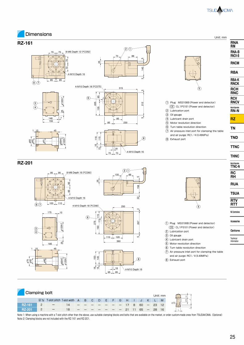
RZ-161 RZ-201○
ー
φ100h7
φ160 or φ200 (Option)
135
φ55H7 (φ50H7 With face plate)
φ40
12H8 (With face plate)
14h7
0.19 【1.90】
40
1/60
33.3/2,000
45
4
Pneumatic
156 【16】
147【15】
75 (150)
150
7,840 【800】
156 【16】
392 【40】
0.48 【4.9】
○
ー
φ120h7
φ200 or φ250 (Option)
160
φ65H7 (φ60H7 With face plate)
φ45
12H8 (With face plate)
18h7
0.19 【1.98】
65
1/72
33.3/2,400
45
4
Pneumatic
294 【30】
264【27】
100 (250)
250
13,720 【1,400】
294 【30】
980 【100】
1.20 【12.3】
R
LHandedness
Spindle diameter
Table diameter *1
Center height
Table T-slot width *1
Guide block width
TPC-Jr TPC-JrController (exclusive)
Inertia converted into motor shaft
Net weight
Speed reduction ratio
Table max. rpm
Indexing accuracy(the sum)
Repeatability
Clamp system
min-1
N・m 【kgf・m】
(Motor rpm: min-1)
kg
sec
arc sec
N・m 【kgf・m】
kg
kg
FN
【kgf】
F×LN・m
【kgf・m】
F×LN・m
【kgf・m】
kg・m2 【kgf・cm・ sec2】
J= W・D2
8
NC Indexer with Programmable Controller
NC Indexer
RZ-201
×10-3kg・m2
【×10-3kgf・cm・sec2】
W
W
F
F
L
F
L
φD
W
Simple structure ensures easy operation. Attractive pricing with many high-performance features.
Specifications
Unit: mm
Single-axis
AC servo: ABS detector
0.001°(Decimal)
1 to 999999 even indexing
1 to 999 even indexing
±999.999°
INC, ABS, Shortcut ABS, INC/ABS mixed system
MDI
Workpiece No. (W0000 to 9999)
1,000 blocks (Total of main and sub programs)
Between rotary table and TPC-Jr (1 pc)
For Motor: 5m
Power cable: 5m
Interlocking cable: 5m
1φ200/220V±10% 50/60Hz
Control box(Non-CE) Weight H2: 6.7kg、H3: 7.2kg
285mm(W)×255mm(D)×130mm(H)
Control axis
Servo motor
Command unit
Indexing number
Direct indexing
Arc-indexing
Max. command angle
Command system
Input system
Program control
Program capacity
Cable supplied (standard)
Power
Grounding (less than 100 ohm earth resistance)
External dimensions
Controller (TPC-Jr) Specifications
Model
Jr H2(for RZ-161)
Jr H3(for RZ-201)
Power capacity
1.2KVA
1.9KVA
Fuse rating
10A
15A
With Face Plate
Nose diameter
Through-bore
Center bore
Clamp torque
/pneumatic pressure 0.49MPa【5kgf/cm2】
Strength of worm gears
Allowable work weight
Allowable load (when table is clamped)
Allowable work inertia
Vertical setting
( ):with tailstock
Horizontal setting
*1 The tolerance of the table T-slot width is applicable to four standard slots arranged crosswise. Dimensions P.61
RZ-161
With Chuck P.56
P.61
NC Rotary Tables
RZ-161・201
24
RNARNRNA-BRNCV-B
RNCM
RBA
RBA-KRNCKRCHRNCRCVRNCVMulti-Spindle
RN-N
RZ
TN
TND
TTNC
THNC
Multi-Spindle
TTNC-N
RCRH
RUA
TSUA
RTVRTT
NC Controllers
Accessories
Options
Technical Information
RNARNRNA-BRNCV-B
RNCM
RBA
RBA-KRNCKRCHRNCRCVRNCVMulti-Spindle
RN-N
RZ
TND
TTNC
THNC
Multi-Spindle
TTNC-N
RCRH
RUA
TSUA
RTVRTT
NC Controllers
Accessories
Options
Technical Information
TN
RZ-161RZ-201
RZ-161
Dimensions
RZ-201
Q’ty
14ー 2
18ー 2
A
ー
ー
ー
ー
ー
ー
ー
ー
ー
ー
ー
ー
ー
ー
17
21
8
11
60
65
ー
ー
23
28
12
16
B C D E F G H I J K L M
Clamping bolt
Unit: mm
Unit: mm
Plug MS3106B(Power and detector)
CE CL1P3101(Power and detector)
Lubrication port
Oil gauge
Lubricant drain port
Motor revolution direction
Turn table revolution direction
Air pressure inlet port for clamping the table
and air purge: RC1/4(0.49MPa)
Exhaust port
1
2
3
4
5
6
7
8
4-M10 Depth 18(PCD75)
1 2 8-M6 Depth 12(PCD52)
7
4-M10 Depth 16
8
7070
7070
88
53
140
25
70
3
315
6
85 5
225
85 230
212
85135
4-M10 Depth 16
8
15115
16116
18
70 70
3
4
φ100h7
25
148 7155
φ40φ65
φ41
φ55H7
φ100h7
15 451
5
8585
7 8
8-M8 Depth 16(PCD60) 9595
4-M10 Depth 16
110100
9595
4-M10 Depth 18(PCD90)
3
4
45
25φ120h7
10175
185
φ46
151
φ75φ45
φ120h7
φ65H7
1516153
145
4-M10 Depth 169595
18
6
5267
360
120110
275
160
115
3
250
1 2
88100
522
158
25
5
Plug MS3106B(Power and detector)
CE CL1P3101(Power and detector)
Lubrication port
Oil gauge
Lubricant drain port
Motor revolution direction
Turn table revolution direction
Air pressure inlet port for clamping the table
and air purge: RC1/4(0.49MPa)
Exhaust port
1
2
3
4
5
6
7
8
Note 1: When using a machine with a T-slot pitch other than the above, use suitable clamping blocks and bolts that are available on the market, or order custom-made ones from TSUDAKOMA. (Optional) Note 2: Clamping blocks are not included with the RZ-161 and RZ-201.
T-slot widthT-slot pitch
8
25
φM
H
JI
L
25

Unit: mm
TN-101Tilt range
Spindle diameter
Table diameter *1
Table height at 0°position
Center height at 90°position
Center bore
Servo motors (for FUNAC)
Inertia converted into motor shaft
Speed reduction ratio
Table max. rpm
Tilting accuracy
Tilting repeatability
Repeatability
Clamp system Supplied pressure
Clamp torque
Net weight
Strength of worm gears(Rotary axis)
min-1 (Motor rpm: 2,000min-1)
kg
N・m 【kgf・m】
Allowable work weight
Allowable work moment
Allowable load (when table is clamped)
Allowable work inertia
0° (Horizontal)
kg
0°~90° (Tilting)
kg
FN
【kgf】
F×L
W×L
N・m 【kgf・m】
F×LN・m
【kgf・m】
kg・m2 【kgf・cm・ sec2】
J= W・D2
8
Specifications
Standard type
NC Tilting Rotary TablesBasic model
×10-3kg・m2
【×10-3kgf・cm・sec2】
Compact tables for speedy and powerful five-axis machining. TN-101 and TN-131 are the most suitable models for drilling and tapping machines.
N・m 【kgf・m】
N・m 【kgf・m】
Tilt 0°~90° arc sec
ー17°~+107°
φ86h7
φ135(Option)
180 (205 With face plate)
135
φ55H7 (φ40H7 With face plate)
φ35
12H8(With face plate)
14h7
Rotary axis Tilt axis
αiF2 αiF2
0.072 【0.73】
0.078 【0.79】
1/60 1/120
41.6
Pneumatic 0.49MPa 【5kgf/cm2】
Pneumatic 0.49MPa 【5kgf/cm2】
16.6
200 【20】
300 【30】
40
ー 45
ー 40
ー 45
ー 30
ー 45
ー 30
ー 45
ー 20
ー 45
ー 15
ー 90
ー 8 ー 8 ー 8 ー 8 ー 8 ー 8
arc sec
arc sec
arc sec
4 ー 4 ー 4 ー 4 ー 4 ー 4 ー
ー
69
152【15.5】
35
20
24 【2.4】
3,920 【400】
200 【20】
300 【30】
0.08 【0.87】
TN-131ー17°~+107°
φ90h7
φ135(Option)
210 (235 With face plate)
150
φ55H7 (φ40H7 With face plate)
φ35
12H8(With face plate)
14h7
Rotary axis Tilt axis
αiF2 αiF2
0.074 【0.75】
0.072 【0.73】
1/60 1/120
41.6
Pneumatic 0.49MPa 【5kgf/cm2】
Pneumatic 0.49MPa 【5kgf/cm2】
16.6
500 【51】
500 【51】
80
152【15.5】
35
20
24 【2.4】
3,920 【400】
500 【51】
500 【51】
0.08 【0.87】
TN-161ー30°~+110°
φ100h7
φ160 or 200(Option)
235 (260 With face plate)
180
φ55H7 (φ50H7 With face plate)
φ40
12H8(With face plate)
18h7
Rotary axis Tilt axis
αiF2 αiF2
0.17 【1.68】
0.18 【1.81】
1/72 1/120
27.7
Pneumatic 0.49MPa 【5kgf/cm2】
Pneumatic 0.49MPa 【5kgf/cm2】
16.6
500 【51】
800 【82】
127
200【20.4】
60
40
39.2 【4.0】
7,840 【800】
500 【51】
800 【82】
0.19 【1.94】
TN-201ー30°~+110°
φ120h7
φ200 or 250(Option)
270 (300 With face plate)
210
φ65H7 (φ60H7 With face plate)
φ45
12H8(With face plate)
18h7
Rotary axis Tilt axis
αiF4 αiF4
0.38 【3.96】
0.45 【4.61】
1/45 1/90
44.4
Pneumatic 0.49MPa 【5kgf/cm2】
Pneumatic 0.49MPa 【5kgf/cm2】
22.2
800 【82】
1,000 【102】
191
450【45.9】
120
70
53.7 【5.5】
13,720 【1,400】
800 【82】
1,000 【102】
0.59 【6.02】
TN-320ー30°~+110°
ー
φ320
355
255
φ105H7
φ102
14H7
18h7
Rotary axis Tilt axis
αiF8 αiF8
0.82 【8.34】
0.45 【4.61】
1/120 1/240
16.6
Hydraulic 3.5MPa
【35kgf/cm2】
Hydraulic 3.5MPa
【35kgf/cm2】
8.3
2,200 【224】
2,200 【224】
440
931【95】
150
100
163.3 【16.6】
19,600 【2,000】
2,200 【224】
2,200 【224】
1.53 【15.6】
TN-450ー10°~+95°
ー
φ450
425
425
φ170H7
φ136
14H7
18h7
Rotary axis Tilt axis
αiF22 αiF22
5.34 【54.5】
3.00 【30.6】
1/90 1/180
22.2
Hydraulic 3.5MPa
【35kgf/cm2】
Hydraulic 3.5MPa
【35kgf/cm2】
11.1
3,700 7,400
1,200
1,940【198】
500
300
288.2 【29.4】
39,200 【4,000】
3,700 【377.6】
7,400 【755.1】
9.38 【95.68】
W
L
W
W
F
F
L
F
L
W
φD
TN-101
Motor rpm: 2,500min-1( ) Motor rpm:
2,500min-1( )
Nose diameter
Through-bore
Table T-slot width *1
Guide block width
Indexing accuracy(the sum)
Servo motors of other manufacturers P.67
*1 The tolerance of the table T-slot width is applicable to four standard slots arranged crosswise. Dimensions P.61
TN-101・131・161・201・320・450
When assembling a faceplate or a fixture with the main spindle P.77
26
RNARNRNA-BRNCV-B
RNCM
RBA
RBA-KRNCKRCHRNCRCVRNCVMulti-Spindle
RN-N
RZ
TN
TND
TTNC
THNC
Multi-Spindle
TTNC-N
RCRH
RUA
TSUA
RTVRTT
NC Controllers
Accessories
Options
Technical Information

RNARNRNA-BRNCV-B
RNCM
RBA
RBA-KRNCKRCHRNCRCVRNCVMulti-Spindle
RN-N
RZ
TND
TTNC
THNC
Multi-Spindle
TTNC-N
RCRH
RUA
TSUA
RTVRTT
NC Controllers
Accessories
Options
Technical Information
TN
TN-131
With Rotary Joint P.64
TN-101
T-slot width
TN-101
Dimensions
TN-131
TN-161
TN-201
TN-320
TN-450
T-slot pitchType Q’ty Layout
1440~160*
abⅠ 4
A
20 12 70 10 35 25 20 12 8 50 35 23 12
TN-131 1440~190*
abⅠ 4 20 12 70 10 35 25 20 17 8 55 35 23 12
TN-161 1878~15063~117
abⅠ 4 20 12 70 10 35 25 17 15 11 55 35 28 16
TN-201 1880~18078~125
abⅠ 4 25 12 80 12 33 35 22 21 11 65 40 28 16
TN-320 18140~19095~180
abⅠ 4 25 12 80 12 33 35 22 21 11 65 40 28 16
TN-450 1880~250*
abⅣ 4 50 20 74 20 18 36 75 10 11 105 70 28 16
B C D E F G H I J K L M
Note: The above dimensions are for FANUC servo motors. The dimensions of servo motors of other manufacturers may be larger.
TN-450
Clamping block and bolt
Unit: mm
Unit: mm HG
IJ
φM
□L D FE
KC
BA
TypeⅠ
Layout a Layout b
15735261
895
656
456
200
341
180
220
3013243
φ105H7
φ106
φ102
255
195
240245 380
425
450
30
φ320
100
1685
575
272
303
272
260 532
286540 605
1145 254
φ450
425675
675
250
260510250
TN-161
With Rotary Joint P.64
194
499
281220
90 100
180
343
179
102
42
100 100
15
40°
1526
11558
1
φ86h7φ55H7
φ36
φ35
202
284
100
524
343
90220
182
102
51185
100 100
2615
0.519
77137.5
40°
φ90h7φ55H7
φ36
φ35
TN-101
Example of scroll chuck use P.56
M
HJ
G
C
D FE
I
K
BA
□L
TypeⅣ
200 200
Note 1: *In the case of layout b, contact us for the details about mounting. Note 2: When using a machine with a T-slot pitch other than the above, use suitable clamping blocks and bolts that are available on the market, or order custom-made ones from TSUDAKOMA. (Optional)
135
134147
220
38
86
180
221
φ86h7
236
86150235
148 134 211 31
φ90h7
4560
φ170H7
φ136
φ140
22208
270
20
60383
210
130
225 192 284
340
227
286
173
459
167 6
335
145
480
701
145 145
57284
155φ120h7φ120h7 φ65H7
φ45.5
φ45
5366
30149
185
386
341
125
240
110
150 6
466
577
285
285
φ100h7
φ100h7φ55H7
161 264152
55
180
105
125 125
125
229
52
15φ40
4561
25131
φ40.5
27

Trunnion type
The Trunnion configuration is at the same level between the Tilting axis and Spindle top of Rotary axis. So this new Tilting table enables highly accurate and productive machining.
TND-160
NC Tilting Rotary TablesBasic model
Unit: mm
TND-130Tilt range
Spindle diameter
Table diameter *1
Center height at 90°position
Center bore
Table T-slot width *1
Guide block width
Servo motors (for FUNAC)
Inertia converted into motor shaft
Speed reduction ratio
Table max. rpm
Indexing accuracy(the sum)
Tilting accuracy
Clamp system Supplied pressure
Clamp torque
Net weight
Strength of worm gears(Rotary axis)
min-1
kg
arc sec
arc sec
arc sec
arc sec
Allowable work weight
Allowable work moment
Allowable load (when table is clamped)
Allowable work inertia
kg
kg
FN
【kgf】
kg・m2 【kgf・cm・ sec2】
Specifications
×10-3kg・m2
【×10-3kgf・cm・sec2】
Repeatability
Tilting repeatability
Nose diameter
Through-bore
ー17°~+107°
φ90h7
φ135(Option)
190 (215 With face plate)
190
φ55H7
φ35
12H8(With face plate)
14h7
ー30°~+110°
φ100h7
φ160 or φ200(Option)
210 (235 With face plate)
210
φ55H7
φ40
12H8(With face plate)
18h7
Rotary axis Tilt axis
αiF2 αiF2
0.127 【1.29】
0.087 【0.88】
1/60 1/120
41.6
Pneumatic 0.49MPa 【5kgf/cm2】
Pneumatic 0.49MPa 【5kgf/cm2】
16.6
500 【51】
500 【51】
40
4
ー
ー
60
8
ー
ー
30
4
ー
ー
75
8
ー
ー
98
152【15.5】
35
20
41.6 【4.2】
3,920 【400】
500 【51】
500 【51】
0.08 【0.87】
TND-160
Rotary axis Tilt axis
αiF2 αiF2
0.191 【1.94】
0.125 【1.27】
1/72 1/180
41.6
Pneumatic 0.49MPa 【5kgf/cm2】
Pneumatic 0.49MPa 【5kgf/cm2】
11.1
500 【51】
800 【82】
140
200【20.4】
60
40
86.3 【8.8】
7,840 【800】
500 【51】
800 【82】
0.19 【1.94】
W
L
W
W
F
F
L
F
L
W
φD
Table height at 0°position
(Motor rpm: 2,000min-1)
N・m 【kgf・m】
Tilt 0°~90°
N・m 【kgf・m】
0° (Horizontal)
0°~90° (Tilting)
W×LN・m
【kgf・m】
F×LN・m
【kgf・m】
F×LN・m
【kgf・m】
J= W・D2
8
Motor rpm: 2,500min-1( ) Motor rpm:
3,000min-1( )
Servo motors of other manufacturers P.67
*1 The tolerance of the table T-slot width is applicable to four standard slots arranged crosswise. Dimensions P.61
ー30°~+110°
φ120h7
φ200(Option)
255 (285 With face plate)
255
φ65H7
φ45
12H8(With face plate)
18h7
30
4
ー
ー
75
8
ー
ー
TND-200
Rotary axis Tilt axis
αiF4/4,000 αiF4/4,000
0.444 【4.53】
0.163 【1.66】
1/45 1/180
44.4
Pneumatic 0.49MPa 【5kgf/cm2】
Pneumatic 0.49MPa 【5kgf/cm2】
11.1
800 【82】
1,000 【102】
215
450【45.9】
120
70
125.3 【12.7】
13,720 【1,400】
800 【82】
1,000 【102】
0.59 【6.02】
TND-130・160・200
28
RNARNRNA-BRNCV-B
RNCM
RBA
RBA-KRNCKRCHRNCRCVRNCVMulti-Spindle
RN-N
RZ
TN
TND
TTNC
THNC
Multi-Spindle
TTNC-N
RCRH
RUA
TSUA
RTVRTT
NC Controllers
Accessories
Options
Technical Information

TND-130
T-slot widthT-slot pitchType Q’ty Layout
1440~210*
abⅠ 4
A
20 12 70 10 35 25 20 17 8 55 35 23 12
TND-160 78~17063~117
abⅠ 4
B C D E F G H I J K L M
Note 1: *In the case of layout b, contact us for the details about mounting. Note 2: When using a machine with a T-slot pitch other than the above, use suitable clamping blocks and bolts that are available on the market, or order
custom-made ones from TSUDAKOMA. (Optional)
Clamping block and boltUnit: mm
18 20 12 70 10 35 25 17 15 11 55 35 28 16
HG
IJ
φM
□L D FE
KC
BA
TypeⅠ
Layout a Layout b
TND-200 80~21078~125
abⅠ 4 18 25 12 80 12 33 35 22 21 11 65 40 28 16
Dimensions
TND-160
Note: The above dimensions are for FANUC servo motors. The dimensions of servo motors of other manufacturers may be larger.
Unit: mm
TND-130
TND-200
φ90h7φ55H740° 15
2677
19
φ36
φ35H8
0.5
137.5
100 100
91185
240
110
386
125
348473
616
186
150 6
φ100h7φ55H7
15
4561
250.5
131.5
φ40.5
φ40
123
125125
82229
φ100h7
315
188152 276
210
105
315
164 231148
275
31
190
86276
φ90h7
100
284
215182
220
90344
574
RTT-111Built-in model which is provided with System 3R or Erowa into the Spindle
173
267
145
338
762
459
227 167 6
483
145145
102
284
0.5
149.5
φ45.5
φ45
φ65H7φ120h7
5366
30
230 307
255
131
225
428
386
φ120h7
103
325
235
180
55
210
25
TN-161(Standard) TND-160Imaginary work piece
55
Imaginary cutting area
TND-160TN-161(Standard)
Tilting degree: 0°
Tilting degree: 90°
Hypothetical machining area
■Trunnion Structure
Comparison of TND and standard table with setting same work piece
High accuracy and productivity at near positional cutting from tilting axis
In TND series, spindle surface of rotary axis is
on the same line with tilting axis
Possible to make machine cutting at near position from tilting axis
High accuracy
Advantage for cutting condition
With wider cutting area and support to intensive production
Tilting axis
High productivity
TND's advantage for machining for same cutting position because of close distance from center of tilting axis
29
RNARNRNA-BRNCV-B
RNCM
RBA
RBA-KRNCKRCHRNCRCVRNCVMulti-Spindle
RN-N
RZ
TND
TTNC
THNC
Multi-Spindle
TTNC-N
RCRH
RUA
TSUA
RTVRTT
NC Controllers
Accessories
Options
Technical Information
TN

Unit: mm
Indexing accuracy(the sum)
Tilting accuracy
Clamp system Supplied pressure
Clamp torque
Net weight
Strength of worm gears(Rotary axis)
kg
Tilt 0°~90° arc sec
arc sec
N・m 【kgf・m】
kg
kg
FN
【kgf】
F×L
W×L
N・m 【kgf・m】
F×LN・m
【kgf・m】
kg・m2 【kgf・cm・ sec2】
J= W・D2
8
Specifications
Standard type
Large tilting models that enable 5-face machining and slanted-hole machining with single chucking of workpiece. Suitable for machining of component parts for heavy industries such as aircraft, power generator and construction machine industry.
N・m 【kgf・m】
N・m 【kgf・m】
Tilting repeatability
TTNC-1001 TTNC-1500 *2
15
4
ー
ー
60
4
ー
ー
ー20°~+110°
ー
φ1000
900
700
φ75H7
ー
22H7
ー
Rotary axis Tilt axis
αiF22 αiF30
4.37 【44.6】
4.1 【41.8】
1/360 1/1,440
5.5
Hydraulic 6.9MPa
【70kgf/cm2】
Hydraulic 6.9MPa
【70kgf/cm2】
1.3
9,800 【1,000】
19,600 【2,000】
4,600
13,230【1,350】
2,500
1,500
7,840 【800】
29,400 【3,000】
9,800 【1,000】
19,600 【2,000】
312.6 【3,188.7】
W
L
W
W
F
F
L
F
L
W
φD
TTNC-1500
15
4
ー
ー
60
4
ー
ー
TTNC-631ー10°~+95°
ー
φ630
585
450
φ180H6
φ180
18H7
18h7
Rotary axis Tilt axis
αiF12 αiF12
5.42 【55.3】
3.77 【38.5】
1/180 1/360
11.1
Hydraulic 3.5MPa
【35kgf/cm2】
Hydraulic 3.5MPa
【35kgf/cm2】
4.1
4,410 【450】
2,352 【240】
1,700
3,284【335】
600
300
980 【100】
24,500 【2,500】
4,410 【450】
2,352 【240】
35.3 【360】
Motor rpm: 1,500min-1( )
20
4
ー
ー
45
8
ー
ー
ー5°~+95°
ー
φ1500
1155
1055
φ75H7
ー
28H7
ー
Rotary axis Tilt axis
TPC3-SR30 TPC3-SR30
5.37 【54.8】
7.46 【76.2】
1/720 1/1,440
Hydraulic 3.5MPa
【35kgf/cm2】
Hydraulic 3.5MPa
【35kgf/cm2】
12,000 【1,224】
25,000 【2,551】
12,000
21,560【2,200】
2,500
1,500
7,840 【800】
49,000 【5,000】
12,000 【1,224】
25,000 【2,551】
2,255 【23,001】
0.7 Motor rpm: 1,000min-1( ) 1.39 Motor rpm:
1,000min-1( )
NC Tilting Rotary TablesBasic model
Tilt range
Spindle diameter
Table diameter
Table height at 0°position
Center height at 90°position
Center bore
Inertia converted into motor shaft
Speed reduction ratio
×10-3kg・m2
【×10-3kgf・cm・sec2】
Nose diameter
Through-bore
Table T-slot width *1
Guide block width
Servo motors (for FUNAC)
Table max. rpm min-1 (Motor rpm: 2,000min-1)
Repeatability arc sec
arc sec
Allowable work weight
Allowable work moment
Allowable load (when table is clamped)
Allowable work inertia
0° (Horizontal)
0°~90° (Tilting)
Servo motors of other manufacturers P.67
*1 The tolerance of the table T-slot width is applicable to four standard slots arranged crosswise.
*2 Above specifications are for one of experienced production. Those might be changed depending on use conditions.
TTNC-631・1001・1500
30
RNARNRNA-BRNCV-B
RNCM
RBA
RBA-KRNCKRCHRNCRCVRNCVMulti-Spindle
RN-N
RZ
TN
TND
TTNC
THNC
Multi-Spindle
TTNC-N
RCRH
RUA
TSUA
RTVRTT
NC Controllers
Accessories
Options
Technical Information

RNARNRNA-BRNCV-B
RNCM
RBA
RBA-KRNCKRCHRNCRCVRNCVMulti-Spindle
RN-N
RZ
TND
TTNC
THNC
Multi-Spindle
TTNC-N
RCRH
RUA
TSUA
RTVRTT
NC Controllers
Accessories
Options
Technical Information
TN
TTNC-631
TTNC-1001
A
18168~45080~267
abⅠ 4 40 20 110 18 42 50 25 21 11 70 46 28 16
24ー ー Ⅱ 8 50 20 74 20 18 36 70 29 16 130 70 40 22
B C D E F G H I J K L M
Clamping block and boltUnit: mm
Note 1: *In the case of layout b, contact us for the details about mounting. Note 2: When using a machine with a T-slot pitch other than the above, use suitable clamping blocks and bolts that
are available on the market, or order custom-made ones from TSUDAKOMA. (Optional)
T-slot widthT-slot pitchType Q’ty Layout
546
478
1024
546
478
1024
Table center boreφ75H7
45
584 584
1055
100
R770
1168
1155
1380 1380
17431743
φ1500
2760
3486
Dimensions
TTNC-1001
TTNC-1500
Note: The above dimensions are for FANUC servo motors. The dimensions of servo motors of other manufacturers may be larger.
Unit: mm
HG
IJ
φM
□L D FE
KC
BA
TypeⅠ
Layout a Layout b
TTNC-631
1875
979896
570 500
φ630
703
810
552 585
450
135
290290
400
φ210
φ181
φ180H6
65240
20
C
FD E
HG J
I
K
B
φM
□L
A
TypeⅡ
Table center bore
632 369
454352
102263
TTNC-1001225
486603
265
2412915985
960
237 435 795 945φ1000
45
φ200φ75H7
900
200
700
150
1000700300
TTNC-1500 28ー ー Ⅱ 10 60 28 95 29 16 50 95 22 17.5 146 100 41.3 24
31

Unit: mm
THNC-251 THNC-301Tilt range
Table diameter *1
Table height at 0°position
Center height at 90°position
Center bore
Net weight
Strength of worm gears(Rotary axis)
kg
N・m 【kgf・m】
kg
kg
FN
【kgf】
F×LN・m
【kgf・m】
F×LN・m
【kgf・m】
kg・m2 【kgf・cm・ sec2】
J= W・D2
8
Specifications
Manual Tilting type
Manual tilt adjustment type with a highly rigid body and a powerful hydraulic clamp system.
Nose diameter
Through-bore
0°~+93°
φ250
230
210
φ40H7
φ32
12H7
18h7
Rotary axis Tilt axis
αiF4 Manual
0.20 【2.0】
ー
1/180 ー
11.1
Hydraulic 3.5MPa
【35kgf/cm2】
Manual 19.6N・m 【2kgf/m】
ー
490 【50】
490 【50】
15
4
60
ー
15
4
60
ー
125
470【48】
80
40
6,860 【700】
490 【50】
490 【50】
0.62 【6.3】
0°~+93°
φ320
265
235
φ40H7
φ40
14H7
18h7
Rotary axis Tilt axis
αiF8 Manual
0.25 【2.6】
ー
1/180 ー
11.1
Hydraulic 3.5MPa
【35kgf/cm2】
Manual 35.3N・m 【3.6kgf/m】
ー
833 【85】
1,862 【190】
180
764【78】
200
100
9,800 【1,000】
833 【85】
1,862 【190】
2.25 【23】
W
W
F
F
L
F
L
W
φD
THNC-251
NC Tilting Rotary TablesBasic model
Clamp system Supplied pressure
Clamp torque N・m 【kgf・m】
Inertia converted into motor shaft
Speed reduction ratio
×10-3kg・m2
【×10-3kgf・cm・sec2】
Table T-slot width *1
Guide block width
Servo motors (for FUNAC)
Indexing accuracy(the sum) sec
Repeatability arc sec
Allowable work weight
0° (Horizontal)
0°~90° (Tilting)
Allowable load (when table is clamped)
Allowable work inertia
Servo motors of other manufacturers P.67
*1 The tolerance of the table T-slot width is applicable to four standard slots arranged crosswise. Dimensions P.61
Table max. rpm min-1 (Motor rpm: 2,000min-1)
THNC-251・301
32
RNARNRNA-BRNCV-B
RNCM
RBA
RBA-KRNCKRCHRNCRCVRNCVMulti-Spindle
RN-N
RZ
TN
TND
TTNC
THNC
Multi-Spindle
TTNC-N
RCRH
RUA
TSUA
RTVRTT
NC Controllers
Accessories
Options
Technical Information

RNARNRNA-BRNCV-B
RNCM
RBA
RBA-KRNCKRCHRNCRCVRNCVMulti-Spindle
RN-N
RZ
TND
TTNC
THNC
Multi-Spindle
TTNC-N
RCRH
RUA
TSUA
RTVRTT
NC Controllers
Accessories
Options
Technical Information
TN
THNC-251
THNC-301
THNC-251
Dimensions
THNC-301
1840~10040~65
abⅠ 4
A
25 12 80 12 33 35 22 21 11 65 40 28 16
1840~13040~80
abⅡ 4 25 15 52 12 15 25 40 21 11 85 40 28 16
B C D E F G H I J K L M
Note: The above dimensions are for FANUC servo motors. The dimensions of servo motors of other manufacturers may be larger.
Clamping block and bolt
Unit: mm
Unit: mm
Layout a Layout b
HG
IJ
φM
□L D FE
KC
BA
TypeⅠ C
FD E
HG J
I
K
B
φM
□L
A
TypeⅡ
(Table at the vertical position)
713
150135
480233
405
225
105
60
164
20124
20
φ45
φ32
φ40H7
460
230230
φ250
225
230
5
20139
30
189
φ40H7
φ50
(Table at the vertical position)
432
165
764
55
172
190
170
φ320
269 254
523
6259
265
T-slot widthT-slot pitchType Q’ty Layout
Note: When using a machine with a T-slot pitch other than the above, use suitable clamping blocks and bolts that are available on the market, or order custom-made ones from TSUDAKOMA. (Optional)
517
150
8085 200
80
371
85
130100
85180
562
387
33

Unit: mm
TTNC-102-2
Minimum distance between table centers
Specifications
Multi-Spindle model
Fully numerically controlled tilt adjustment type enables highly productive machining, in which simultaneous machining of multiple workpieces with complex shapes or five faces is possible.
ー17°~+107°
φ90h7
φ135(Option)
230 (255 With face plate)
160
φ55H7 (φ40H7 With face plate)
φ35
140
12H8(With face plate)
14h7
ー110°~+110°
φ80h7
φ115(Option)
275 (300 With face plate)
200
φ50H7 (φ50H7 With face plate)
φ30
120
10H8(With face plate)
18h7
ー110°~+110°
ー
φ160
270
200
φ35H7
φ35
250
12H7
18h7
ー110°~+110°
ー
φ225
350
260
φ40H7
φ32
304.8
12H7
18h7
Rotary axis Tilt axis
αiF2 αiF2
0.16 【1.6】
0.06 【0.6】
1/90 1/180
22.2
Pneumatic 0.49MPa 【5kgf/cm2】
Pneumatic 0.49MPa 【5kgf/cm2】
11.1
127 【13】
284 【29】
40
4
ー
ー
45
4
ー
ー
60
8
ー
ー
60
4
ー
ー
30
4
ー
ー
60
4
ー
ー
20
4
ー
ー
60
4
ー
ー
100
93.1【9.5】
35
20
54.8 【5.6】
1,960 【200】
127 【13】
284 【29】
0.08 【0.86】
TTNC-101-4
Rotary axis Tilt axis
αiF8 αiF8
0.52 【5.3】
1.08 【11.0】
1/60 1/90
33.3
Pneumatic 0.49MPa 【5kgf/cm2】
Hydraulic 3.5MPa
【35kgf/cm2】
22.2
80 【8】
980 【100】
370
176【18】
25
25
176 【26】
1,960 【200】
80 【8】
980 【100】
0.05 【0.5】
TTNC-151-2
Rotary axis Tilt axis
αiF4 αiF8
0.45 【4.6】
1.09 【11.1】
1/90 1/90
22.2
Pneumatic 0.49MPa 【5kgf/cm2】
Hydraulic 3.5MPa
【35kgf/cm2】
22.2
78 【8】
1,000 【102】
340
147【15】
40
40
156.8 【16】
6,860 【700】
78 【8】
980 【100】
0.19 【2.0】
TTNC-201-2
Rotary axis Tilt axis
αiF8 αiF12
0.48 【4.9】
3.2 【32.8】
1/90 1/120
22.2
Hydraulic 3.5MPa
【35kgf/cm2】
Hydraulic 3.5MPa
【35kgf/cm2】
16.6
490 【50】
2,450 【250】
550
470【48】
50
50
254.8 【26】
9,800 【1,000】
490 【50】
2,450 【250】
0.63 【6.4】
W
L
W
W
F
F
L
F
L
W
φD
TTNC-151-2
*2 *2
*2
*2
NC Tilting Rotary Tables
Tilt range
Spindle diameter
Table diameter *1
Table height at 0°position
Center height at 90°position
Center boreNose diameter
Through-bore
Indexing accuracy(the sum)
Tilting accuracy
Clamp system Supplied pressure
Clamp torque
Net weight
Strength of worm gears(Rotary axis)
kg
arc sec
Tilt 0°~90° arc secarc sec
N・m 【kgf・m】
kg
kg
FN
【kgf】
F×L
W×L
N・m 【kgf・m】
F×LN・m
【kgf・m】
kg・m2 【kgf・cm・ sec2】
J= W・D2
8
N・m 【kgf・m】
N・m 【kgf・m】
Tilting repeatability
Inertia converted into motor shaft
Speed reduction ratio
×10-3kg・m2
【×10-3kgf・cm・sec2】
Table T-slot width *1
Guide block width
Servo motors (for FUNAC)
Table max. rpm min-1 (Motor rpm: 2,000min-1)
Repeatability arc sec
Allowable work weight
Allowable work moment
Allowable load (when table is clamped)
Allowable work inertia (per single-axis)
0° (Horizontal)
0°~90° (Tilting)
Servo motors of other manufacturers P.67
*1 The tolerance of the table T-slot width is applicable to four standard slots arranged crosswise. *2 Tables with increased clamp torque are available according to the applications.Dimensions P.61
225 225
(spindles) TTNC-102-2(spindles)・101-4(spindles) TTNC-151-2(spindles)・201-2(spindles)
34
RNARNRNA-BRNCV-B
RNCM
RBA
RBA-KRNCKRCHRNCRCVRNCVMulti-Spindle
RN-N
RZ
TN
TND
TTNC
THNC
Multi-Spindle
TTNC-N
RCRH
RUA
TSUA
RTVRTT
NC Controllers
Accessories
Options
Technical Information

RNARNRNA-BRNCV-B
RNCM
RBA
RBA-KRNCKRCHRNCRCVRNCVMulti-Spindle
RN-N
RZ
TND
TTNC
THNC
Multi-Spindle
TTNC-N
RCRH
RUA
TSUA
RTVRTT
NC Controllers
Accessories
Options
Technical Information
TN
TTNC-102-2
Dimensions
TTNC-101-4
TTNC-151-2
TTNC-201-2
Note: The above dimensions are for FANUC servo motors. The dimensions of servo motors of other manufacturers may be larger.
TTNC-101-4
TTNC-102-2
TTNC-151-2
With Power Chuck P.57
With Rotary Joint P.64
Unit: mm
RT-161
315
100
φ190
709295
85140±0.0270
70
φ90h7φ90h7
16547371
252
160
100 100
R137
R82
(PCD45)
(PCD70)
4-M5 Depth 10
4-M8 Depth 14
5
φ55H7
40°
φ36
φ35
135
1526
190
261
327
175
36680120120120115393
φ80h7
75
175
200
850 110354
392
175175
14545
φ50H7φ80h7
φ30
This twin-spindle type NC tilting table has the world's largest diameter of 450mm.
260445
168975255
440
225φ225 225φ225160 160
624.81398
400
195
180
212
71
200200
194395
165
21
φ45
φ32124
φ40H7
20
304.8±0.02
200 360360
765 149230
70
125 1255001144
195
190
71
350
147
175175
322 165
15149
φ35H7
φ35
114
20
φ36
φ160 φ160250±0.02
35

Unit: mm
RC-250 RC-300 RC-400 RC-500φ250
230
αiF8
130
1/36
0.68 【6.94】
55.5
25
4
Hydraulic
540 【55】
660【67】
300
350
19,600 【2,000】
540 【55】
931 【95】
2.36 【24.0】
φ320
250
αiF12
200
1/45
1.36 【13.9】
44.4
25
4
Hydraulic
900 【91】
966【98】
450
700
29,400 【3,000】
900 【91】
2,000 【204】
7.1 【69.5】
φ400
260
αiF22
290
1/45
2.30 【23.5】
44.4
25
4
Hydraulic
1,900 【193】
1,535【156】
650
960
39,200 【4,000】
1,900 【193】
4,000 【408】
10.9 【106.8】
φ500
270
αiF22
390
1/90
3.60 【36.7】
22.2
25
4
Hydraulic
3,400 【346】
2,815【287】
650
960
39,200 【4,000】
3,400 【346】
4,000 【408】
33.5 【328.3】
Table diameter
Servo motors (for FUNAC)
Table height
Indexing accuracy(the sum)
Repeatability
Clamp system Clamp torque
/Hydraulic pressure 3.5Mpa【35kgf/cm2】
Strength of worm gears
N・m 【kgf・m】
Table max. rpm min-1
(Motor rpm: 2,000min-1)
Speed reduction ratio
Net weight kg
sec
arc sec
N・m 【kgf・m】
Allowable work weight
Allowable load (when table is clamped)
Allowable work inertia
kg
Eccentric load N・m
FN
【kgf】
F×LN・m
【kgf・m】
F×LN・m
【kgf・m】
kg・m2 【kgf・cm・ sec2】
J= W・D2
8
Specifications
Horizontal setting type with rotary joint
NC Rotary Tables developed for specific machines
Inertia converted into motor shaft ×10-3kg・m2
【×10-3kgf・cm・sec2】
W
F
F
L
F
L
φD
W
High-performance NC rotary tables developed for specific machines requiring high rigidity and durability. Used mainly for processing workpieces or jigs. Equipped with a rotary jo int unit having 8 ports ( for pneumatic and hydraul ic pressure) and 1 port (for coolant) as standard features.
W
L
Servo motors of other manufacturers P.67
For horizontal setting
NC Rotary Tables developed for specific machines
Available for horizontal setting only. Used mainly for rotating and positioning operations on items like cradle jigs which have a comparably large turning radius. Tables equipped with a powerful clamp system have excellent loading capacity and moment rigidity.
RH-600
RH-400・500・600
RC-300
RC-250・300・400・500
36
RNARNRNA-BRNCV-B
RNCM
RBA
RBA-KRNCKRCHRNCRCVRNCVMulti-Spindle
RN-N
RZ
TN
TND
TTNC
THNC
Multi-Spindle
TTNC-N
RCRH
RUA
TSUA
RTVRTT
NC Controllers
Accessories
Options
Technical Information

RNARNRNA-BRNCV-B
RNCM
RBA
RBA-KRNCKRCHRNCRCVRNCVMulti-Spindle
RN-N
RZ
TND
TTNC
THNC
Multi-Spindle
TTNC-N
RCRH
RUA
TSUA
RTVRTT
NC Controllers
Accessories
Options
Technical Information
TN
RC-□□□
TSUA-□□□ RUA-□□□
RH-□□□
TSUA-□□□ RUA-□□□ TSUA-□□□ RUA-□□□
■Examples of Combined UseTurn & Tilt System Tilt & Turn System Cradle System
RC-250
Dimensions
RC-300
RC-400
RC-500
Note: The above dimensions are for FANUC servo motors. The dimensions of servo motors of other manufacturers may be larger.
Unit: mm
A-port
J-port
B-portC-portD-port
E-portF-port G-port
H-port
8-φ8(Divided equally) (PCD52)
566
280140
278
165
230
27195
150
345
65178
140
115
133
115 12
23324
286
288
22.5°
φ220
φ250
φ30
φ22H7
φ14
1.8±0.05
2.4±0.05
(PCD72)
B-portA-port
C-portD-port
E-portF-port G-port
H-port
J-port
8-φ11.5(Divided equally)
φ320
25068182
35
22.5°
1.8±0.05
15
2.4±0.05
φ18
φ25
φ30H7
φ40
φ280
407
230
177
210
157
150145
368 312198170
358
53
680
(PCD90)
A-portB-portC-port
D-port
E-portF-port G-port
H-port
J-port
8-φ11.5(Divided equally)
φ400
26068192
351.8±0.05
φ25
φ18
2.4±0.05
φ40
φ30H7
15
22.5°
φ360
358
104
465200
265245
180
312443
755
233210
180180
φ18
(PCD90)
A-port
J-port
B-portC-port
8-φ11.5(Divided equally) D-port
E-portF-port G-port
H-port
22.5°
1.8±0.05
φ25
2.4±0.05φ40
15φ30H7
φ500
27068202
35
860225225
548 312293255
358
204
570
320
250
300
225
37

Unit: mmSpecifications
For vertical setting
Built-in Specialized NC Rotary Tables
Available for vertical setting only. Used mainly as a tilting device. An optional 8~12-port rotary joint* is available. Tables equipped with a powerful dual disc clamp system have excellent eccentric load rigidity, powerful wheel torque and cutting resistance.
RUA-250 RUA-320 RUA-400 RUA-500
Table diameter
11.1
30
4
Hydraulic
1,000
1,500
938
120
29,400 【3,000】
2,450 【250】
3,626 【370】
17.8 【174】
39,200 【4,000】
4,200 【428】
5,880 【600】
29.9 【293】
49,000 【4,000】
6,100 【622】
13,132 【1,340】
74.2 【727】
8.3
160
8.3
25
4
Hydraulic
4,200
6,300
3,276
30
4
Hydraulic
2,450
4,200
1,942
200
5.5
25
4
Hydraulic
6,100
9,200
4,930
250
Vertical setting
φ250
170
φ105H7
φ71
αiF8/3,000
0.40
120
1/180
Vertical setting
φ320
210
φ140H7
φ101
αiF12/3,000
2.07
270
1/240
Vertical setting
φ400
255
φ190H7
φ151
αiF22/3,000
2.38
390
1/240
Vertical setting
φ500
310
φ220H7
φ182
αiF30/3,000
2.46
620
1/360
Setting
Servo motors (for FUNAC)
Center height
Center bore
Indexing accuracy(the sum)
Repeatability
Clamp system
Clamp torque
Table max. rpm
Speed reduction ratio
Net weight kg
Vertical/Horizontal
sec
arc sec
Inertia converted into motor shaft ×10-3kg・m2
/Hydraulic pressure 3.5 Mpa
/Hydraulic pressure 4.9 Mpa
N・m
N・m
N・m
Allowable work weight
kg
Allowable load (when table is clamped)
Allowable work inertia
F
F×L
F×L
J= W・D2
8
F
F
L
F
L
φD
W
Nose diameter
Through-bore
min-1
(Motor rpm: 2,000min-1)
RUA-320
RUA-500
* Number of ports may vary depending upon models.
W
N 【kgf】
N・m 【kgf・m】
N・m 【kgf・m】
kg・m2 【kgf・cm・ sec2】
19,600 【2,000】
1,000 【102】
980 【100】
6.0 【59】
Strength of worm gears
RTT-501・Table square size:□500 ・When using support spindle with balance cylinder
RUA-250・320・400・500
38
RNARNRNA-BRNCV-B
RNCM
RBA
RBA-KRNCKRCHRNCRCVRNCVMulti-Spindle
RN-N
RZ
TN
TND
TTNC
THNC
Multi-Spindle
TTNC-N
RCRH
RUA
TSUA
RTVRTT
NC Controllers
Accessories
Options
Technical Information

RNARNRNA-BRNCV-B
RNCM
RBA
RBA-KRNCKRCHRNCRCVRNCVMulti-Spindle
RN-N
RZ
TND
TTNC
THNC
Multi-Spindle
TTNC-N
RCRH
RUA
TSUA
RTVRTT
NC Controllers
Accessories
Options
Technical Information
TN
RUA-250
Dimensions
RUA-320
RUA-400
RUA-500
Note: The above dimensions are for FANUC servo motors. The dimensions of servo motors of other manufacturers may be larger.
Unit: mm
φ71
28
117
15
6
φ120
φ75H8
φ105H7
145 150
170
516
221 162
383
5 193
302
5
φ250
φ255
φ210H8
φ182
φ220H7
40225
25260 260
310
892
327
587
φ500
35
446
335
φ151
157 1061
φ190H7
φ165H8
φ225
235 235
255
783
242
477
2955
375
φ400
φ101
φ107
46 108 50 13φ140H7
φ115H8
φ175
185185
210
698
187 215
402
5 280
366φ320
28
32
40
39
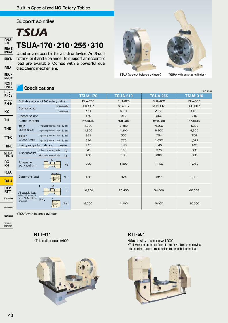
Unit: mmSpecifications
Support spindles
Built-in Specialized NC Rotary Tables
Used as a supporter for a tilting device. An 8-port rotary joint and a balancer to support an eccentric load are available. Comes with a powerful dual disc clamp mechanism.
TSUA(without balance cylinder) TSUA(with balance cylinder)
860
16,954
2,000
25,480
4,900
34,000
8,400
42,532
10,300
1,300 1,730 1,950
RUA-250
φ105H7
φ71
170
Hydraulic
1,000
1,500
281
394
±45
70
100
RUA-320
φ140H7
φ101
210
Hydraulic
2,450
4,200
550
770
±45
140
180
RUA-400
φ190H7
φ151
255
Hydraulic
4,200
6,300
754
1,077
±45
270
300
RUA-500
φ190H7
φ151
310
Hydraulic
4,200
6,300
754
1,077
±45
300
330
Suitable model of NC rotary table
Center height
TSUA Clamp torque TSUA *
balance torque Swing range for balancer degree
TSUA Net weight
Allowable load ( when table is clamped under 3.5Mpa hydraulic pressure )
kg
FN
Clamp system
169 374 627 1,036Eccentric load N・m
F×LN・m
*TSUA with balance cylinder.
/Hydraulic pressure 3.5 Mpa N・m
/Hydraulic pressure 4.9 Mpa N・m
/Hydraulic pressure 3.5 Mpa N・m
/Hydraulic pressure 4.9 Mpa N・m
without balance cylinder
with balance cylinder
kg
kg
F
L
TSUA-170 TSUA-210 TSUA-255 TSUA-310
RTT-504・Max. swing diameter:φ1000 ・To lower the upper surface of a rotary table by employing the original support mechanism for an unbalanced load
・Table diameter:φ400
RTT-411
W
F
L
W
Center boreNose diameter
Through-bore
Allowable work weight
TSUA-170・210・255・310
40
RNARNRNA-BRNCV-B
RNCM
RBA
RBA-KRNCKRCHRNCRCVRNCVMulti-Spindle
RN-N
RZ
TN
TND
TTNC
THNC
Multi-Spindle
TTNC-N
RCRH
RUA
TSUA
RTVRTT
NC Controllers
Accessories
Options
Technical Information
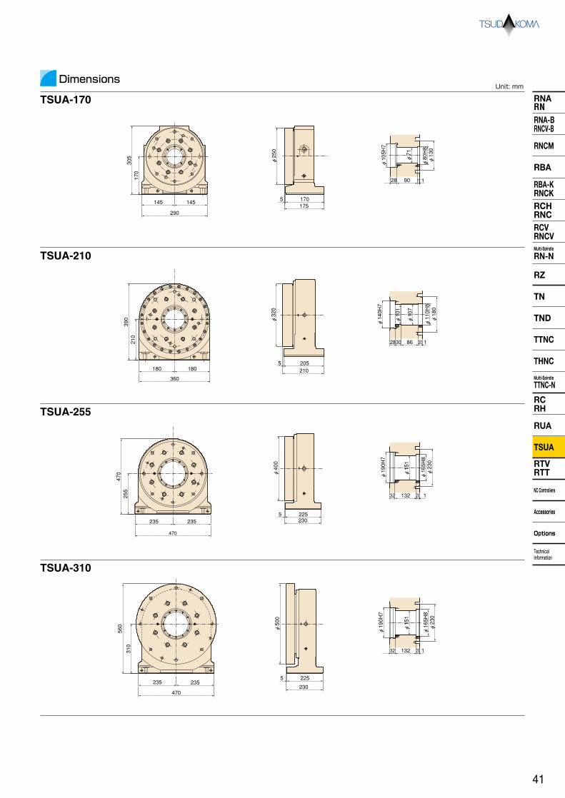
RNARNRNA-BRNCV-B
RNCM
RBA
RBA-KRNCKRCHRNCRCVRNCVMulti-Spindle
RN-N
RZ
TND
TTNC
THNC
Multi-Spindle
TTNC-N
RCRH
RUA
TSUA
RTVRTT
NC Controllers
Accessories
Options
Technical Information
TN
DimensionsUnit: mm
TSUA-170
TSUA-210
TSUA-255
TSUA-310
145 145
170305
290
28 90 11 1
φ105H7
φ71
φ80H8
φ130
5 170175
φ250
210
180 180
360
390
2830 86 20 1
φ140H7
φ101
φ107
φ110H8
φ180
2055210
φ320
235 235
255
470
470
32 132 20 1
φ190H7
φ151
φ165H8
φ230
5 225230
φ400
235 235
310
560
470
32 132 20 1
φ151
φ165H8
φ230
φ190H7
5 225
230
φ500
41

30 190 40260
7
φ120h7 φ25H8
φ25.5
φ65H7
φ46
φ35
20321813945 6260
10-φ8(Divided equally) (PCD160)
No10-Port(for coolant) No9-Port
No8-PortNo7-Port
No6-PortNo5-PortNo4-Port
No3-PortNo2-PortNo1-Port
No10-Port
No9-Port
No8-Port
No7-Port
No6-PortNo5-Port No4-Port
No3-Port
No2-PortNo1-Port
265 265
265
265530
530
φ537
φ551
φ200
3576.550100
290390
130130373
190
135
325
220
R135
6060
408 25396 286
142
142
444
225
219 113
243
59
7177 296148148
335
280
h7
116107253408
415
110661
44507209298
φ100
φ500 DD Table
Unit: mmSpecifications
DD Table
Direct Drive ( DD ) Motor NC Rotary Table
RTV-202
Dimensions
φ500DD Table
DD (Direct Drive) motors realize high speed, high acceleration and backlash-free operation. Most suitable for high speed and high quality machining for various impellers, blades and medical equipment, and for high speed indexing operation for automotive parts. Provides optimum ideas and products based upon versatile applications as well as their sales record.
Unit: mm
RTV-202
Controll axis
Table diameter(Spindle diameter) mm
Servo motors (for FUNAC)
Type of scale
Table max. rpm min-1
Clamp torque N・m
Center height mm
Rotary joint
Allowable work weight kg
Net weight kg
RTV-2021-axis
Vertical setting only
(φ120)
Dis260/300
αCZi512S
150
300(Pneumatic pressure 0.49MPa)
190
─
50
90
φ500 Table1-axis
Horizontal setting only
φ537
─
RCN226
60
3,800(Hydraulic pressure 4.9MPa)
─
9P+1P
700
485
*Contact us for the following models. Vertical type DD Table φ100~φ500 Horizontal type DD Table φ300~φ630 Tilting type DD Table φ100~φ630 *Applicable for various kinds of DD motors which depend upon the type of controllers. Contact us for details.
RTT-112
Rotary axis
φ100
Dis60/400
αCZi512A
150
─
Tilt axis
φ100
Dis150/300
αCZi512A
100
80(Pneumatic pressure 0.49MPa)
2-axis
280
─
30
190
RTT-112
RTT-112
RTV-202・φ500 TableRTT-112
・
42
RNARNRNA-BRNCV-B
RNCM
RBA
RBA-KRNCKRCHRNCRCVRNCVMulti-Spindle
RN-N
RZ
TN
TND
TTNC
THNC
Multi-Spindle
TTNC-N
RCRH
RUA
TSUA
RTVRTT
NC Controllers
Accessories
Options
Technical Information

Unit: mmSpecifications
Unit: mm
RTV-304
RTV-404
RTV-504
RTV-801
Motor position
Right or Left
Top
Right or Left
Top
Right or Left
Top
Right
A
235
235
280
280
350
350
530
B
435
423
525
510
625
554
981
C
221
668
266
748
296
863
429
D
481
123
577
133
594
134
759
E
350
350
450
450
550
550
800
F
265
265
300
300
325
325
375
G
190
190
250
250
315
315
460
H
160
160
209
209
269
269
420
I
22
22
30
30
30
30
48
J
234
234
256
256
280
280
318
Dimensions
φE
F
C D
BA
φE
F
D
B
AC
Side motor application Top motor application
RTV-304 RTV-404 RTV-504 RTV-801○
○
○
φ350
235
φ190H7
φ160
14H7
18h7
αiF12
2.7 【27.54】
180
1/90
22.2
15
4
Hydraulic
2,700 【102】
1,370【139】
300 (500)
500
29,400 【3,000】
2,700 【275】
3,626 【370】
10.0 【102】
○
○
○
φ450
280
φ250H7
φ209
14H7
18h7
αiF22
4.05 【41.31】
430
1/90
22.2
15
4
Hydraulic
4,600 【469】
2,630【268】
350 (700)
700
45,000 【4,590】
4,600 【469】
8,000 【816】
20.0 【204】
○
○
○
φ550
350
φ315H7
φ269
18H7
18h7
αiF22
6.01 【61.30】
590
1/120
16.6
15
4
Hydraulic
5,800 【591】
4,200【428】
500 (1,000)
1,000
54,000 【5,508】
5,800 【591】
15,132 【1,543】
30.0 【306】
○
○
○
φ800
530
φ460H7
φ420
18H7
22h7
αiF12
4.35 【44.37】
1,370
1/360
5.5
15
4
Hydraulic
14,500 【1,479】
7,840【800】
600 (1,500)
1,500
64,400 【6,568】
14,500 【1,479】
27,000 【2,754】
120.0 【1,224】
R
L
Top
Nose diameter
Through-bore
Handedness
Table diameter
Center height
Center bore
Table T-slot width
Guide block width
Servo motors (for FUNAC)
Inertia converted into motor shaft
Net weight
Speed reduction ratio
Table max. rpm
Indexing accuracy(the sum)
Repeatability
Clamp system
Clamp torque
/hydraulic pressure 3.5MPa【35kgf/cm2】
Strength of worm gears
min-1
N・m 【kgf・m】
(Motor rpm: 2,000min-1)
kg
sec
arc sec
N・m 【kgf・m】
Allowable work weight
Allowable work inertia
Vertical setting kg
Horizontal setting kg
F N 【kgf】
F×L N・m 【kgf・m】
F×L N・m 【kgf・m】
kg・m2 【kgf・cm・ sec2】
J= W・D2
8
( ):with tailstock
×10-3kg・m2
【×10-3kgf・cm・sec2】
W
W
F
F
L
F
L
φD
W
I
J
φG(H7)
φH
High-rigidity models with a super big bore
Main spindle with highly rigid bearings and table with high overall rigidity enable machining of hard materials such as aircraft components. Vertical and horizontal setting types are available. Machining at a position closer to the face plate is made possible by inserting the workpiece through the large bore.
RTV-404(Top motor application) RTV-404(Side motor application)
RTV-304・404・504・801
Allowable load ( when table is clamped )
RNARNRNA-BRNCV-B
RNCM
RBA
RBA-KRNCKRCHRNCRCVRNCVMulti-Spindle
RN-N
RZ
TND
TTNC
THNC
Multi-Spindle
TTNC-N
RCRH
RUA
TSUA
RTVRTT
NC Controllers
Accessories
Options
Technical Information
TN
43
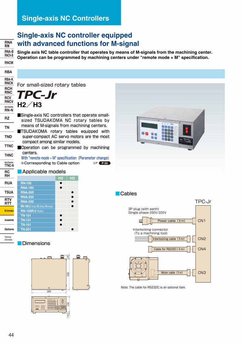
RNARNRNA-BRNCV-B
RNCM
RBA
RBA-KRNCKRCHRNCRCVRNCVMulti-Spindle
RN-N
RZ
TN
TND
TTNC
THNC
Multi-Spindle
TTNC-N
RCRH
RUA
TSUA
RTVRTT
NC Controllers
Accessories
Options
Technical Information
■Cables
■Dimensions
For small-sized rotary tables
Single-axis NC Controllers
Single-axis NC controller equipped with advanced functions for M-signal Single axis NC table controller that operates by means of M-signals from the machining center. Operation can be programmed by machining centers under "remote mode + M" specification.
CN1
CN4
CN3
TPC-Jr
Power cable(5m)
Cable for RS232C(5m)
Motor cable(5m)
Interlocking cable(5m)
3P plug (with earth) Single phase 200V/220V
Interlocking connector (To a machining tool)
CN2
■Applicable models
RN-100RNA-160RNA-200RNA-250RNA-320
RN-150R-2(Axis)
TN-101TN-131TN-161TN-201
H2 H3
RN-100-2(Axis)/3(Axis)/4(Axis)
●
●
●
●
●
●
●
●
●
●
Note: The cable for RS232C is an optional item.
P.50
■Single-axis NC controllers that operate small-sized TSUDAKOMA NC rotary tables by means of M-signals from machining centers.
■TSUDAKOMA rotary tables equipped with super-compact AC servo motors are the most compact among similar models.
■Operation can be programmed by machining centers.
With "remote mode + M" specification (Parameter change) ※Corresponding to Cable option
VA¥U+2205V
MODEL
50,60HZ No.
TSUDAKOMA Corp.
MADE IN JAPAN
(29)
255
285
130
(10)
JOG
TPC-Jr
+ JOG
- JOG -
SINGLE
RUN
DGN
θ
+
7
NW No.
2nd・F
MODE
2nd・F
USER
PRG
CLR
DEL
2
5
8FEED
POS
FG
COPY
INS
1
0MLK
CALM
4
AUTO
STOP
SPSTM ZRN
W ZRN
CHECK
MDI
PROG
RREM
PRM
9
6
CR
3DIR
SCH
H2/H3
44

RNARNRNA-BRNCV-B
RNCM
RBA
RBA-KRNCKRCHRNCRCVRNCVMulti-Spindle
RN-N
RZ
TND
TTNC
THNC
Multi-Spindle
TTNC-N
RCRH
RUA
TSUA
RTVRTT
NC Controllers
Accessories
Options
Technical Information
TN
TPC-Jr FUNCTIONS
No. G0 G1 G2 G3 G4 G5 G6 G7 G8 G9
001~999 000 001~999 001~999 000~100 000 001 002 001~999 000 001/002 003/004 005/006 007/008 009/010 011 012 013
Number of repetitions (INC) (ABS) Number of repetitions Number of divisions, Number of repetitions Number of table rotations 1st zero point return (mechanical zero point) 2nd zero point return 3nd zero point return Number of repetitions Not required Not required Not required No operation Clamp OFF/ON Dowel OFF/ON Indexing group control OFF/ON Directional positioning OFF/ON Completion signal control command OFF/ON Program display selection command Current position display selection command Remaining angle display selection command
Command angle Command angle Number of divisions for 360° Arc-angle indexed Command angle Sub-program No. Target address Reference coordinate Dwell time Completion signal selection
±000.001°~999.999° ±000.000°~360.000° ±1~999999div. ±000.001°~360.000° ±0°~360.000° 0000~9999 000~999 ±0°~360.000° 000~999 (×10m sec)
Direct angle command Direct indexing number command Arc-indexing number command Lead cutting command Zero point return command Sub-program call command Subprogram return command Program end command Workpiece coordinate system setting command Declaration command
Command Command Command SettingNo.
G-code R-code θ-code
Not required
Not required
Not required
Not required
Not required
Program edit keys
Mode display lamps
Mode change keys
Operation keys
Power switchLiquid display 20 figures×2 lines
(Program/current position)
■Operation panel
Program edit keys
Workpiece No.(Program No.) + 0000~ 9999 100 programs registerable
NW No.
2nd・F
Block No.000~999
NW No.
Operation commandG0~G4: Movement command G5 to G9: Assistance function
GPRO
Feed rate select commandF0: Rapid positioning speed F1~ F9: Cutting feed rate
FPOS
Assistance code for codesRREM
Travel distance command (angle, divided number) Block No./Sub-program No.
θ DGN
OPERATION MODE
AUTO AUTO: Automatic operation by an M signal from the machining center.
Single operation of TPC-Jr. By pressing , the indexing is done one time.
STSINGLE SINGLE:
CHECK CHECK: Block number call, program check and self-diagnosis.
PROG Program mode: For inputting and editing the program.
MDI MDI mode: For setup operation. Ten blocks of programs can be carried out.
JOG JOG mode: For manual feed and step feed.
45

RNARNRNA-BRNCV-B
RNCM
RBA
RBA-KRNCKRCHRNCRCVRNCVMulti-Spindle
RN-N
RZ
TN
TND
TTNC
THNC
Multi-Spindle
TTNC-N
RCRH
RUA
TSUA
RTVRTT
NC Controllers
Accessories
Options
Technical Information
Single-axis NC Controllers
■Applicable models
■Cables
■Dimensions
For large-sized tables
T ERSE
TE
RSE
TE
RSE
A
5-100 Awada,Nonoichi-machiIshikawa-gun,Ishikawa,Japan
KVA, A at 200V
SHORT CIRCUIT INTERRUPTING CAPACITY
RATED INPUT: V 50,60Hz -ph
DISCONNECT POWER SUPPLY BEFORE SERVICING
CN6
CN2 CN3 CN4
CN5
CN1
CN8
STOPRUN
READYALARM
POWER
377235
380
(19)
T ERSE
TE
RSE
TE
RSE
A
5-100 Awada,Nonoichi-machiIshikawa-gun,Ishikawa,Japan
KVA, A at 200V
SHORT CIRCUIT INTERRUPTING CAPACITY
RATED INPUT: V 50,60Hz -ph
DISCONNECT POWER SUPPLY BEFORE SERVICING
CN6
CN2CN3CN4
CN5
CN1
CN6
CN2CN3CN4
CN5
CN1
CN8
STOPRUN
READYALARM
POWER
MDI unit
I/O equipment for general programming (Supplied by user)
Power cablePower cable, with 4P plug
Interlocking cable (standard)/ Fully-equipped interlocking cable (optional)
Interlocking plug with 2m lead wire
B-signal plug with 2m lead wire
B signal cable (optional)Motor power
cable
TPC5 control unit
CN4
CN5 CN6
CN1
MDI cable
Cable for RS232C (optional)
Rotary Table Motor detector cable
CN3CN3CN2CN2
+-
COPY
INS
1
0MLK
CALM
4
AUTO
2nd・F
θ DGN
MODE
2nd・F RUN
-
7
W No.
NSINGLE
+
USER
PRG
G
CLR
DEL
2
5
8FEED
POS
F
SCH
DIR
3
CR
6
9PRM
REM
R
PROG
MDI
CHECK
ZRNW
ZRNM
ST SP
STOP
HANDLE
x100x10x1
TPC5 control unit
MDI unit
P.50
■Single-axis NC controllers automatically start large-sized TSUDAKOMA NC rotary tables by receiving M-signals from machining centers.
■Easy programming by simple input of the interactive system.
In increments of 0.001°(standard), 0.0001°or 1 sec.
■Ready to set optional functions easily. ★With an optional function of B signal, the workpiece number, block number and tilting angle command can be entered from a machining center.
★With "remote mode + M specification", operation can be programmed by a machining center.
RNCM-251RNCM-301~631RBA-250RBA-320,400RCV-800
RNCV-1201,1501
TN-450THNC-251THNC-301TTNC-631
SR6 SR12 SR30
RCV-1000
TN-320
●
●
●
●
●
●
●
●
●
●
●
●
SR6/SR12/SR30
46

RNARNRNA-BRNCV-B
RNCM
RBA
RBA-KRNCKRCHRNCRCVRNCVMulti-Spindle
RN-N
RZ
TND
TTNC
THNC
Multi-Spindle
TTNC-N
RCRH
RUA
TSUA
RTVRTT
NC Controllers
Accessories
Options
Technical Information
TN
■Operation panel
Program edit keys
Multiple jog dial
Operation mode change key
LED displays
Operation keys
LED for operational mode
Indicator
Status display line: ●①TPC status ●②Workpiece number ●③Subprogram number ●④Command system
Program display line: TPC5 program in 2 lines ●⑤Current position/remaining (POS/REM)
Control display line: ●⑥Overtravel ●⑦Override/machine lock/manual interrupt ●⑧Zero point return MZRN/WZRN/TZRN
←Status display line
←Program display line
←Program/Current position
←Control display line
RDY W0000 S9999 ABS
N000 G0 F0 R0000
●⑤POS θ+000°00'00''
OT OVR150% MZRN
●① ●② ●③ ●④
●⑥ ●⑦ ●⑧
CN6
CN2CN3CN4
CN5
CN1
CN3CN2
TPC5 FUNCTIONS
Program edit keys
Block No.000~999
NW No.
Operation commandG0~G4: Movement command G5 to G9: Assistance function
GPRO
Feed rate select commandF0: Rapid positioning speed F1~ F9: Cutting feed rate
FPOS
Assistance code for codesRREM
Travel distance command (angle, divided number)
θ DGN
AUTO AUTO: Automatic operation interlocked with machining center
Single operation of TPC5SINGLE SINGLE:
CHECK CHECK: Program check and self-diagnosis
PROG Program mode:
Program entry
MDI MDI mode: Setup operation
HANDLE Handle mode: Manual pulse operation/jog mode
OPERATION MODE
No. G0 G1 G2 G3 G4 G5 G6 G7 G8 G9
0001~9999 0000 0001~9999 0001~9999 0000~0100 0000 0001 0002 0000~9999 0000 0001/0002 0003/0004 0005/0006 0007/0008 0009/0010 0011 0012 0013
Number of Repetition (INC command) (ABS command) Number of repetitions Number of divisions, Number of repetitions Number of table rotations 1st zero point return (mechanical zero point) 2nd zero point return 3nd zero point return Number of repetitions Not required Not required Not required No operation Clamp OFF/ON Dowel OFF/ON Indexing group control OFF/ON Directional positioning OFF/ON Completion signal control command OFF/ON Program display selection command Current position display selection command Remaining angle display selection command
Command angle Command angle Number of divisions for 360° Arc-angle indexed Command angle Sub-program No. Target address Reference coordinate Dwell time Completion signal selection
±000.001°~999.999° ±000.000°~360.000° ±1~999999div. ±000.001°~360.000° ±0°~360.000° 0000(0001)~9999 000~999 ±0°~360.000° 001~999 (×10m sec)
Direct angle command Direct indexing number command Arc-indexing number command Lead cutting command Zero point return command Sub-program call command Subprogram return command Program end command Workpiece coordinate system setting command Declaration command
Command Command Command SettingNo.
G-code R-code θ-code
Not required
Not required
Not required
Not required
Not required
Workpiece No.(Program No.) + 0000~ 9999 100 programs registerable
NW No.
2nd・F
47

RNARNRNA-BRNCV-B
RNCM
RBA
RBA-KRNCKRCHRNCRCVRNCVMulti-Spindle
RN-N
RZ
TN
TND
TTNC
THNC
Multi-Spindle
TTNC-N
RCRH
RUA
TSUA
RTVRTT
NC Controllers
Accessories
Options
Technical Information
Specifications of TPC
Control axis
Servo motor
Command unit
Indexing number
Direct indexing
Arc-indexing
Max. command angle
Command system
Input system
Program control
Program capacity
Positioning speed
Display
Direct indexing number command
1 axis
AC servo: ABS detector
0.001°(Decimal) 1 sec,0.001°,0.0001°(Decimal)
1~999999 even indexing
1~999 even indexing 1~9999 even indexing
±999.999° ±999°59'59'',±999.999°,±999.9999°
INC, ABS, Shortcut ABS, INC/ABS mixed system
MDI
Workpiece No. (W0000 to 9999)
Liquid crystal display 20 figures× 2lines Liquid crystal display 20 figures× 4lines
Move angle is directly commanded
Repetition Command of number of move amount repetitions 999(TPC-Jr) 1~9999(TPC5)
Direct indexing number command Indexing number of six digits for 360 degrees
Arc-indexing number command Command of arbitrary 3-digit angle(TPC-Jr)or 4-digit angle(TPC5)
Interlocked operation with one axis of the machining center in the open loop status
Lead cutting command
Zero point return command Allows return to the first, second or third-zero point
Feedrate command F0: positioning speed F1~9: cutting feedrate
Feedrate setting 1. By radius and surface speed setting 2. By move amount per second
Sub-program Up to eight levels of nesting are possible
Workpiece coordinate system setting Allows a workpiece coordinate to be set at any point
Dwell Allows output of a positioning completion signal to be delayed
Single directional positioning Allows positioning in one direction
Backlash compensation In increments of 0.001°
Soft limit function Sets a soft limit measured from the 1st zero position
Automatic setting at power ON
1. Mode selection, AUTO/CHECK
2. Workpiece number setting 3.Block number setting
Edit function 1. Insert 2. Delete 3. COPY
Alarm 1. Program format errors
2. Program memory errors
3. Communication errors4. Soft limit alarms5. Overtravel6. Servo motor alarms7. Overheat in the cabinet(TPC5)
JOG/HANDLE feeding
Override function × 5~200% 5% steps
Jog feed, step feed Manual pulse feed, jog feed
Overtravel The rotation range of the rotary table can be limited by limit switches. (Standard tilting axis)
Manual 2nd zero setting
Enables the 2nd zero position to be set and changed at any point in the JOG(HANDLE)mode
Input/output signal check ○
Contrast The concentration on the LCD screen can be adjusted
Power 1φ200/220V±10% 50/60Hz
Model Power capacity Fuse rating Model Power capacity Fuse rating
Jr H2
Jr H3
1.2KVA
1.9KVA
10A
15A
3φ200/220V±10% 50/60Hz
TPC5-SR6
TPC5-SR12
TPC5-SR30
2.3KVA
4.0KVA
5.9KVA
10A
15A
20A
Earth (less than 100 ohm earth resistance)
Environmental conditions Ambient temperature: 0-40 degree Relative humidity: 20-80%(no condensation) Vibration: 0.3G or less, No corrosive gas Jr H2 unit285mm(W)×255mm(D)×130mm(H)
Weight: 6.7kg
Jr H3 unit285mm(W)×255mm(D)×130mm(H)
Weight: 7.2kg
Control unit235mm(W)×377mm(D)×380mm(H)
Weight: 15kg
MDI unit111mm(W)×30mm(D)×199mm(H)
Weight: 0.5kg
External output signal From TPC to machining center Contact ratings: DC24V, 0.1A or less
1,000 blocks (Total of main and sub programs) 2,000 blocks (Total of main and sub programs)
Max, motor rotation speed: 3,000rpm
Operation Mode AUTO: Operation interlocked with a machining centerSINGLE: Single operation of TPCCHECK: Program check and callPROG: Program editMDI: Setup operationJOG: Manual feed, step feed
AUTO: Operation interlocked with a machining centerSINGLE: Single operation of TPCCHECK: Program check and callPROG: Program editMDI: Setup operationHANDLE: Manual pulse operation
Max, motor rotation speed: 2,000rpm
TPC-Jr TPC5FIN1 Positioning completion signal during interlocking operation
● ●
FIN2 Output of G7 completion or workpiece number setting completion (selectable by parameters)
●(AUTO mode) ◇
FIN3 Output of G7 completion or workpiece number setting completion (selectable by parameters)
× ◇
FIN4 Output of zero position (selectable by parameters)
× ◇
Workpiece number
setting completion
Output at workpiece number setting completion (selectable by parameters)
● ◇
In AUTO mode Output in AUTO mode
× ◇
LEVEL Output during positioning (selectable by parameters)
●(Rotary table zero position) ◇
ALARM Output in AUTO mode
External input signal From machining center to TPC (External power DC24V is also available.)
● ◇
START Positioning start signal during interlocking operation (M-signal)
● ●
STOP Input to stop rotary table
● ●
INTERLOCK Input to interlock rotary table
× ◇
Workpiece number can be set externally
● ◇
BF(Strobe signal)
Strobe signal for setting workpiece number externally
● ◇
M-signal
MDI lock Input for locking MDI key operation
× ◇
Zero point return 1st zero return command
● ◇
Manual pulse generator
Manual operation can be performed with a manual pulse generator
× ●(Movement magnification:×1,×10,×100)
Full-closed feedback control
Enable full-closed control (highly precise) with the Inductsyn or rotary encoder×
MP scale
Encoder
Detecting unit 0.0001°(360poles) or 0.00005°(720poles)
× ◆
Detecting unit 0.0001°or 0.00005°
× ◆
Serial channel
Cable supplied (standard)
TPC program, feed rate and parameters can be stored in an external device
◆(RS232C) ◆(RS232C)
Format: ISO Format: ISO
Between rotary table and TPC-Jr(1 pc) For Motor: 5m
Cable supplied (Option)
Cables of different length are available
ー
Power cable: 5m
Interlocking cable: 5m
Between rotary table and TPC5(2 pcs.) For motor power supply: 5m For motor detector: 5m
Between TPC5 and MDI unit: 7m
Power cable: 5m
Interlocking cable: 5m
RS232C cable: 5m
ー
ー
Interlocking cable: 5m
B signal cable: 5m
RS232C cable: 5m
TPC-Jr TPC5
●:Standard
◇:Optional interlocking cables are supplied
◆:Optional units and parts are supplied
Single-axis NC Controllers
Setting by command unit
Weight
Selection of outer program
M signal data fixed input system
●(6 points) ◇(16 points)
48

RNARNRNA-BRNCV-B
RNCM
RBA
RBA-KRNCKRCHRNCRCVRNCVMulti-Spindle
RN-N
RZ
TND
TTNC
THNC
Multi-Spindle
TTNC-N
RCRH
RUA
TSUA
RTVRTT
NC Controllers
Accessories
Options
Technical Information
TN
TPC Option
Full-featured interlocking cable●Full-featured interlocking cable (Standard length: 5m)
Required for the following functions:
・Stop or interlock input signal ・Positioning completion 2,3,4 ・AUTO mode ・Positioning ・Alarm signal
●B signal cable (Standard length: 5m)
※For using B signal cable,internal harness shall be added.
Required for the following functions:
・External input of workpiece numbers ・External input of angles ・Fixed data input through M-signal
●RS232C cable (Standard length: 5m)
●Rotary encoders ●IBV unit (by HEIDENHAIN) ●TPC5 RE
●MP scale ●Pre-amplifier ●A/D converter (Mitsubishi Heavy Industries) ●TPC5 RE
●RS232C cable
●RS232C cable
5m 2m
5m 2m
B signal cable
RS232C cable
High Resolution CapabilityRotary Encoder Type
High Resolution CapabilityMP Scale type
"Remote Mode" Specification
"Remote Mode + M" Specification
Input and output of program, parameter and feed data for TPC5 and TPC-Jr, and data printout are carried out through external equipment, which is to be prepared by the customer. Also, the cables can be arranged by the customer.
Available for measuring system construction. To be connected with a personal computer using serial channel.
To unify the program to start the rotary table by M-signal, by feeding a command for the indexing angle from the RS232C port at the NC controller of the machining center.Note: This function may not be available for
some machining centers. For details, ask the manufacturer.
Fully-closed loop control is possible by the feed-back from the rotary encoder.
Fully-closed loop control is possible by the feed-back from the MP scale.
TPC5
TPC5
TPC-Jr
TPC5
TPC5
TPC5
TPC-Jr
TPC5
TPC-Jr
TPC5
P.53
P.62
P.62
P.50
49

RNARNRNA-BRNCV-B
RNCM
RBA
RBA-KRNCKRCHRNCRCVRNCVMulti-Spindle
RN-N
RZ
TN
TND
TTNC
THNC
Multi-Spindle
TTNC-N
RCRH
RUA
TSUA
RTVRTT
NC Controllers
Accessories
Options
Technical Information
TPC Machining Program Examples by TPC Controller
Remote mode + M specification(Parameter change) ※corresponding to Cable option
TPC-Jr
Machining center NC unit
(For the TPC-Jr)
Command
FIN
M-signal
RS-232C
FPOS
FPOS
FPOS
RREM
RREM
θ DGN
θ DGN
NW No.
NW No.
NW No.
NW No.
NW No.
NW No.
NW No.
NW No.
NW No.
GPRO
GPRO
GPRO
GPRO
GPRO
GPRO
Direct angle command:G0
90°
90°
Direct indexing number command(even indexing): G1
90° 90°
90° 90°
Arc-indexing number command(even indexing by an arbitrarily-set angle): G2
90°
Uneven indexing70° 74.635°
90° 125.365°
(-) direction indexing
-90°
Zero point return command: G4
Program using Custom Macro
Zero position
FPOS
FPOS
RREM
RREM
RREM
θ DGN
θ DGN
θ DGN
θ DGN
CR
CR
CR
CR
CR
CR
CR
Positioning at 70° once
Positioning at 90° once
Positioning at 125.365° once
Positioning at 74.635° once
Return to 000 at the program end
000
001
002
003
004
000 0 0 002 90.000
001 7 000
0
0
0
0
7
0
0
0
0
001
001
001
001
70.000
90.000
125.365
74.635
000
GPRO
θ DGN
End of program
Positioning at 90° twice Return to 000 at the program end
FPOS
RREM
θ DGN
NW No.
NW No.
NW No.
GPRO
CR
CR
000 1 0 004 000004d
001 7 000
GPRO
θ DGN
Dividing 360° by 4, four times Return to 000 at the program end
360° is divided into quarters
FPOS
RREM
θ DGN
NW No.
NW No.
NW No.
GPRO
CR
CR
000 2 0 005 120.000
001 7 000
GPRO
θ DGN
Dividing 120° by 5, five times Return to 000 at the program end
Angle for indexingIndexing number
RREM
NW No. 000 4 000G
PROReturn to 1st zero position
To 1st zero positionZero return
FPOS
RREM
θ DGN
NW No.
NW No.
NW No.
GPRO
CR
CR
000 0 0 001 -90.000
001 7 000
GPRO
θ DGN
Positioning at -90° once Return to 000 at the program end
Reverse
Machining center:
Necessary equipment TPC-Jr: Software for remote mode RS232C/interlock cable, RS232C cross cable
NC unit for a machining tool: RSS232C connector and Custom Macro B (optional) (for FANUC). For details, ask the machine manufacturer.
RS232C port opens Command of absolute positioning at 90 is transmitted to TPC Positioning starts Machining center in operation Command of absolute positioning at 180 is transmitted to TPC Positioning starts Machining center in operation RS232C port closes
Quick Number of Repetition Indexing angle/time
The rotary table is controlled via TPC with M-signal sent from a machining center through RS232C.
Single-axis NC Controllers
Note: This function may not be available for some machining centers. For details, ask the manufacturer.
90°
90°
POPEN; DPRINT[/MOVA90.]; M70; GO1Z100.F200; DPRINT[/MOVA180.]; M70; GO1Z100.F200; PCLOS;
50

RNARNRNA-BRNCV-B
RNCM
RBA
RBA-KRNCKRCHRNCRCVRNCVMulti-Spindle
RN-N
RZ
TND
TTNC
THNC
Multi-Spindle
TTNC-N
RCRH
RUA
TSUA
RTVRTT
NC Controllers
Accessories
Options
Technical Information
TN
Installation of TPC controller
1
3
2
4
Power supply
M-signal
Air supply
Stand The figure shows an example for the TPC-Jr controller.
CouplerCoupler Air hose
Air source in the plant
RC1/4
To be provided by customers
①Air supply
②M-signal
③Power supply
④Stand A stand for the TPC controller is to be provided by the customer.
When the machining center controls the rotary table, it uses M-signals. Be sure to confirm with the machine manufacturer that M-signals or M-signal completion signals are transferred to the terminal block of the machine controller. If not, ask the manufacturer to do the required work.
A pneumatic or air-hydraulic clamp system is available for an NC rotary table mounted with the TPC5 or TPC-Jr controller, and an air supply is required.
The following are to be provided by customers: ●Air filter and regulator (Air pressure:0.49 MPa) ●Air hose or air tube ●Joint coupler (RC 1/4 for the table)
Some models need a 6mm diameter tube for connection.
P.52For the connection with an interlocking cable, refer to the examples shown on
A socket for the TPC controller is necessary. A 3P plug is equipped with the TPC controller, and is recommended. The outlet for the connection is required. TPC side connector WF4420(Panasonic) Outer power supply connector WF1420 or the others(Panasonic) In case of the different type of connector,shall be arranged by the customer.
Conduct grounding (less than 100 ohm earth resistance)
P.48For the power capacity of each controller, refer to
For the dimensions and weight of the controller, refer to P.48P.44~46
51

RNARNRNA-BRNCV-B
RNCM
RBA
RBA-KRNCKRCHRNCRCVRNCVMulti-Spindle
RN-N
RZ
TN
TND
TTNC
THNC
Multi-Spindle
TTNC-N
RCRH
RUA
TSUA
RTVRTT
NC Controllers
Accessories
Options
Technical Information
5m 2m
Interlocking cable (Standard length: 5m)
Connector dimension (on machining center)
Connector dimension (To machining center)
φ21
Electric cabinet of machining center
Terminal block for M-signal
AT71
AT70
AT85
AT84
M70
FIN
Start
Input common signal
M signal finish
Output common signal
a) When a start signal and an indexing completion signal are used:
b) When all the signals through interlocking cables are used:
a) Standard interlock cable For interlocking only with M-signal and the completion signal
Electric cabinet of machining center
Stop
Output common signal
B2
Terminal block for M-signal
M70Start
Input common signal
AT71
AT91AT92AT93AT73AT72
AT82
M71Zero return
AT75
B1AT76
ALM Alarm signal
FIN1 Positioning finish 1
FIN2 Positioning finish 2
LVL Level signal
AT70AT85
B4B8BF
AT88AT89AT84
TPC Controllers to Interlock with Machining Tools
M70StartStop
Input common signalPositioning finish
Output common signal
AT71
AT72
AT70
AT85
AT84
Electric cabinet of machining center
MIX FIN
5m 2m
Interlocking cable(Standard length: 5m)
4-M3
□27
φ26
Single-axis NC Controllers
Note 1: When completion signals are received by a relay, the power supply should be 24VDC. Do not apply 100VAC or 200VAC.
Note 2: By changing the switch in the controller, a start signal is also available with the external power supply of DC24V. Note 3: Be sure to take countermeasures against electric noise by attaching surge protectors to relays for a machining center.
52
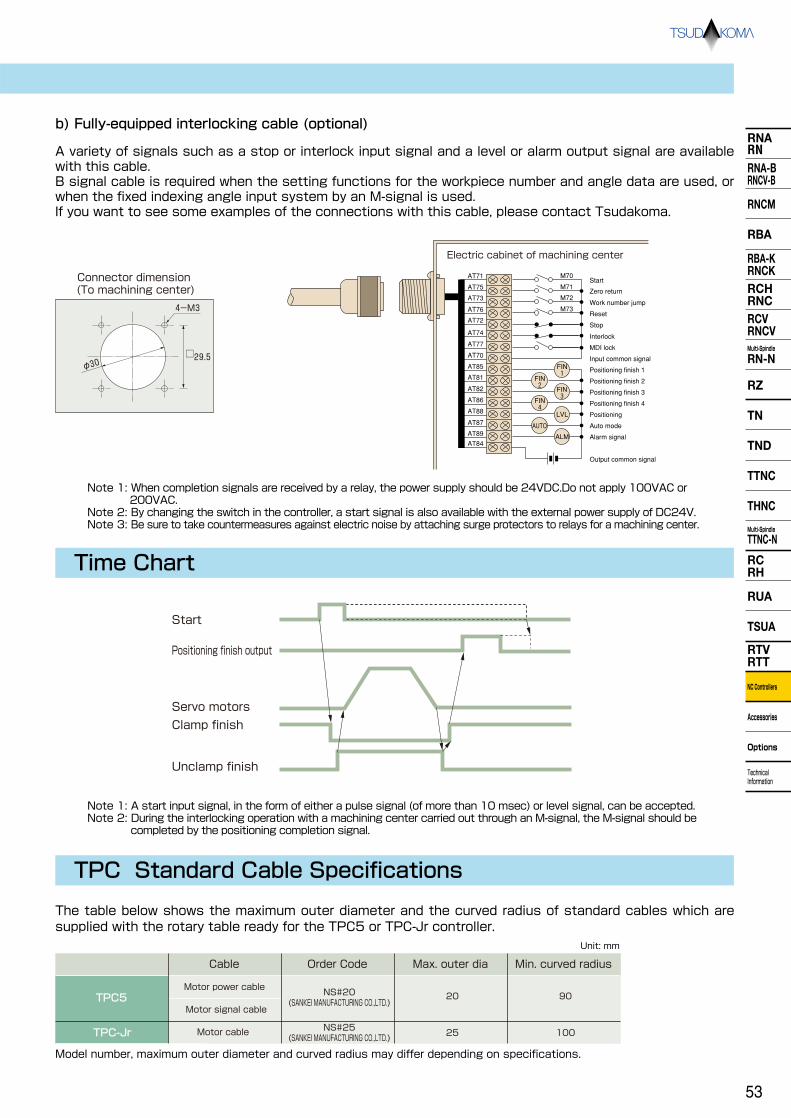
RNARNRNA-BRNCV-B
RNCM
RBA
RBA-KRNCKRCHRNCRCVRNCVMulti-Spindle
RN-N
RZ
TND
TTNC
THNC
Multi-Spindle
TTNC-N
RCRH
RUA
TSUA
RTVRTT
NC Controllers
Accessories
Options
Technical Information
TN
TPC Standard Cable Specifications
The table below shows the maximum outer diameter and the curved radius of standard cables which are supplied with the rotary table ready for the TPC5 or TPC-Jr controller.
TPC5
TPC-Jr
Cable
Motor power cable
Motor signal cable
Motor cable
Order Code
NS#20 (SANKEI MANUFACTURING CO.,LTD.)
NS#25 (SANKEI MANUFACTURING CO.,LTD.)
Max. outer dia
20
Min. curved radius
90
25 100
Model number, maximum outer diameter and curved radius may differ depending on specifications.
Unit: mm
b) Fully-equipped interlocking cable (optional)
Connector dimension (To machining center)
4-M3
φ30 □29.5
Electric cabinet of machining center
AT71 M70Start
Output common signal
Interlock
MDI lock
Input common signal
Positioning finish 1
Positioning finish 2
Positioning finish 3
Positioning finish 4
Positioning
Auto mode
Alarm signal
Stop
Reset
Work number jump
Zero returnM71
M72
M73
FIN 1
LVL
ALM
AUTO
FIN 3
FIN 2
FIN 4
AT75
AT73
AT76
AT72
AT74
AT77
AT70
AT85
AT81
AT82
AT86
AT88
AT87
AT89
AT84
A variety of signals such as a stop or interlock input signal and a level or alarm output signal are available with this cable. B signal cable is required when the setting functions for the workpiece number and angle data are used, or when the fixed indexing angle input system by an M-signal is used. If you want to see some examples of the connections with this cable, please contact Tsudakoma.
Note 1: When completion signals are received by a relay, the power supply should be 24VDC.Do not apply 100VAC or 200VAC.
Note 2: By changing the switch in the controller, a start signal is also available with the external power supply of DC24V. Note 3: Be sure to take countermeasures against electric noise by attaching surge protectors to relays for a machining center.
Start
Positioning finish output
Servo motors
Clamp finish
Unclamp finish
Time Chart
Note 1: A start input signal, in the form of either a pulse signal (of more than 10 msec) or level signal, can be accepted. Note 2: During the interlocking operation with a machining center carried out through an M-signal, the M-signal should be
completed by the positioning completion signal.
53

RNARNRNA-BRNCV-B
RNCM
RBA
RBA-KRNCKRCHRNCRCVRNCVMulti-Spindle
RN-N
RZ
TN
TND
TTNC
THNC
Multi-Spindle
TTNC-N
RCRH
RUA
TSUA
RTVRTT
NC Controllers
Accessories
Options
Technical Information
NC Rotary Tables/TPC-Jr Dimensions and Specifications
NC Table Specifications (with TPC-Jr)
TPC-Jr
Reduction ratio
Max. rpm min-1
RN-100
H2
1/36
66.6/Motor 2,400
RNA-160
H2
1/72
41.6/Motor 3,000
RNA-200
H3
1/72
41.6/Motor 3,000
RNA-250
H3
1/120
25/Motor 3,000
RNA-320
H3
1/180
16.6/Motor 3,000
RN-100-2
H3
1/36
55.5/Motor 2,000
RN-100-3
H3
1/60
50/Motor 3,000
RN-100-4
H3
1/60
50/Motor 3,000
RN-100R/TPC-Jr H2
RNA-160R/TPC-Jr H2
RNA-200R/TPC-Jr H3
RNA-250R/TPC-Jr H3
RNA-320R/TPC-Jr H3
Unit: mm
4-M5 Depth 8
φ6H7 Depth 1045° 22.5°
45
φ30H8
φ50H7
15
145
190
260
180
110
6060
70 8-M6 Depth 10
Note 1: Other specifications Note 2: Consult us before an eccentric load is applied to the table due to continuous cutting feed or jigs.
P.8 P.22
Single-axis NC Controllers
2809085
195
220
135 216
45° 6-M10 Depth 20φ10H7 Depth 12
1094515
φ55H7 φ40H8
7 148
φ100h7
270
235
264
160
115105340
45° 6-M10 Depth 20φ10H7 Depth 12
45 11915
φ65H7 φ45H8
7 158
φ120h7
240
360120 120
285
160
279
22.5°
(PCD110)
8-M10 Depth 20 (Divided equally)
φ10H7 Depth 15
1194515
φ80H7 φ50H8
7 158
φ140h7
364
370
210
275
155430
155
22.5°
(PCD140)
8-M12 Depth 24 (Divided equally)
φ10H7 Depth 15
1644515
φ115H7 φ85H8
7 203
φ180h7
(Equal indexing PCD68) (Divided equally PCD68)
Six points out of 8 equally divided sections: PCD75( )
Six points out of 8 equally divided sections: PCD90( )
145
139φ80h7
/
54

RNARNRNA-BRNCV-B
RNCM
RBA
RBA-KRNCKRCHRNCRCVRNCVMulti-Spindle
RN-N
RZ
TND
TTNC
THNC
Multi-Spindle
TTNC-N
RCRH
RUA
TSUA
RTVRTT
NC Controllers
Accessories
Options
Technical Information
TN
NC Tilting Table Specifications (with TPC-Jr)
Control axis
TPC-Jr
Reduction ratio
Max. rpm min-1
TN-101/TPC-Jr H2
TN-131/TPC-Jr H2
TN-161/TPC-Jr H2
TN-201/TPC-Jr H3
Unit: mm
433
146122
103
100
224
277
112 134 180 7
220
86135 221
φ86h7
100100
115
151
582615
φ86h7
φ36
φ35
φ55H740°
TN-101
H2
1/120
16.6/Motor 2,000
Tilt
1/60
41.6/Motor 2,500
Revolution
TN-131
H2
1/120
16.6/Motor 2,000
Tilt
1/60
41.6/Motor 2,500
Revolution
TN-161
H2
1/120
16.6/Motor 2,000
Tilt
1/72
41.6/Motor 3,000
Revolution
TN-201
H3
1/90
22.2/Motor 2,000
Tilt
1/45
44.4/Motor 2,000
Revolution
Note 1: Other specifications Note 2: Consult us before an eccentric load is applied to the table due to continuous cutting feed or jigs.
P.26
With face plate (Option)
458
146133
324
100
277
90
224
1112
236
235
211134
86150
φ90h7
0.5
9626
15
40°
φ90h7φ55H7
φ35H8
100100
240
125
6
365
547
110
297
156
129
285
285
φ100h7
161 264122
55
180
105
125 125
125
15
φ55H7φ100h7
φ40H8
4561
25131
φ40.5
60
φ120h7
φ120h7
210
130
192 284
340
345
157
6
290
145
435
633
135
322
157146
145 145
155
φ65H7
φ45.5
φ45H8
5366
30
149
/
55

RNARNRNA-BRNCV-B
RNCM
RBA
RBA-KRNCKRCHRNCRCVRNCVMulti-Spindle
RN-N
RZ
TN
TND
TTNC
THNC
Multi-Spindle
TTNC-N
RCRH
RUA
TSUA
RTVRTT
NC Controllers
Accessories
Options
Technical Information
Accessories
Chuck
(( Chuck type Outer chucking range(mm)
Inner chucking range(mm)
4 0 0
5 0
6 0
7 0
9
TC110F
TC130F
TC165F
TC190F
TC230F
TC273F
TC310F
TC385F
TC460F
3 ~ 130
2~ 106
3~ 156
3~ 184
4~ 214
10 10~ 246
12 10~ 275
15 15~ 345
18 15~ 410
102
42~
36~
128
52~ 148
56~ 174
64~ 202
72~ 230
82~ 265
100~ 327
152~ 436
A B C D E F G H I J
Scroll ChuckD C B A
φJ
φE
φF
φG
φH
φI
Chuck
Chuck flange
RN-100
RNA-250
RNA-320
RNCM-251
RNCM-301
RBA-250
RBA-320
RBA-400
RBA-500
RZ-161
RZ-201
RNA-160
RNA-200
RNCM-401
RNCM-501
Chuck size(inch)4
5145 10
58
60
31.3
37.350 50
24
32
112
132
112
13230
5
18
60 37.3 32 132 132
6 155 66 44.3 55 45 44 167 167 40
7 75 46.3 54 192 192
6 18
18
25
66 44.3 44 167 167
7 175 75 46.3 65 55 54 192 192 45
9 82 55.3 70 233 233
518
60 37.3 32 132 132
4 58 31.3 24 112 112
6155
66 44.3 45
44 167 167
7 75 46.3 54 192 192
6
18
18
18
18
18
25
66 44.3 44 167 167
5 60 37.3 32 132 132
7165
75 46.3 55
54 192 192
9 82 55.3 70 233 233
5 60 37.3 32 132 132
6165
66 44.3 65
44 167 167
7 18 75 46.3 54 192 192
9 25 82 55.3 70 233 233
6 18
18
66 44.3 44 167 167
7 75 46.3 54 192 192
9 210 82 55.3 100
55
65
80
115
40
45
50
8570 233 233
10
25
25
25
86 53.3 100 274 274
12 92 59.3 110 310 310
5 60 37.3 32 132 168
6165
20
20
20
66 44.340 30
44 167 16732
7 75 46.3 54 192 198
9 25 82 55.3 70 233 233
6 20
20
66 44.3 44 167 208
7 75 46.3 54 192 238
9 220 82 55.3 40 30 70 233 233 40
10
25
25
25
86 53.3 100 274 274
12 92 59.3 110 310 318
7 20 75 46.3
54 192 238
9 82 55.340 30
70 233 23340
10
25
25
25
86 53.3 100 274 274
12 92 59.3 110 310 318
9300 25
82 55.350 40
70 233 28850
12 92 59.3 110 310 378
6 18
18
66 44.3 44 167 208
7 180 75 46.3 95 54 192 236 71
9 25 82 55.3 70
65
65
76 233 233
6 18 66 44.3 44 167 216
18 2467 75 46.3 54 192
9 240 82 55.3 130 101 70 233 286 101
10
25
25
25
86 53.3 100 274 318
31812 92 59.3 110 310
7 20 75 46.3 54 192 286
9 82 55.3 70 233 286
10 275
25
25
25
86 53.3 190 151 100 274 336 151
12 92 59.3 110 310 370
15 30 100 70.3 150 385 385
9 25
25
82 55.3 170 70 233 356
12325
92 59.3220
110 310 386182
15 30 100 70.3 150 385 460
18 35 114 79.8 180
210
210
210 460 500
250
Note 1: The above dimensions refer to power chucks by KOBAYASHI IRON WORKS CO., LTD. Note 2: The flange type and the method of attaching the flange fixing bolt differ depending on the rotary table and the chuck size.
Chuck size (inch)
Unit: mm
Note 1: The values in the table above are the dimensions with hardened jaws. (Soft jaws are optional.) Note 2: Some workpieces, even in the chucking range, may not be chucked due to jaw configuration.
56

RNARNRNA-BRNCV-B
RNCM
RBA
RBA-KRNCKRCHRNCRCVRNCVMulti-Spindle
RN-N
RZ
TND
TTNC
THNC
Multi-Spindle
TTNC-N
RCRH
RUA
TSUA
RTVRTT
NC Controllers
Accessories
Options
Technical Information
TN
Note: The above dimensions refer to power chucks by HOWA MACHINERY, LTD. A front-mounting pneumatic chuck is also available.
Hydraulic cylinder dimensions
A B C D E F G H I
RNCM-251
RNCM-301
RNCM-401
4
5
6
6
8
10
8
10
27
43
43
43
52
72
20
24
72
85
95
85
95
20
24
35
35
165
220
250
61
36
35
36
39
36
39
175
175
190
197
190
197
500
540
570
609
629
110
135
165
165
210
254
210
254
160
27 52 500 185
215
225
270
315
270
315
639
659
Power chuck
Pneumatic cylinder dimensions
A B C D E F G H I
RNA-160
RNA-200RNA-250
RNA-320
RNCM-251
RNCM-301
RNCM-401
4
5
6
4
5
6
6
8
10
4
27
43
27
43
43
27
43
43
43
52
27 52
72
52
27 52
72
72
85
95
52
52
18
20
24
24
35
35
155
165
210
165
220
250
64
67
76
67
182
190
200
200
243
258
182
552
506
484
513
518
564
625
692
717
513
110
135
165
110
135
165
165
210
254
110
-
-
-
160
27
35
1855
6
6
8
10
8
10
35
35
72
20
20
24
72
85
95
85
95
200
190
182
64
50
64
64
64
64
190 518 135
200 568 165 215
34 200 593 165 225
39 243 665 210 270
44 258 695 254 315
39 243 695 210 270
44 258 725 254 315
FEG
DCBA
φH
φI
Revolving cylinder
ChuckChuck flange
Example of pneumatic power chuck use
Unit: mm
Chuck sizeOrder Code (inch) A
TN-101
TN-131
TN-161
TN-201
TN-320
4
5
5
4
5
6
7
5
6
7
9
6
7
9
10
12
9
10
12
15
180
210
235
270
355
425
Chuck size(inch)
Chuck size(inch)
B
135
150
180
210
255
425
C
45
60
55
60
100
0
D
15
18
18
18
25
18
25
25
30
E
58
60
60
58
60
66
75
60
66
75
82
66
75
82
86
92
82
86
92
100
F
31.3
37.3
37.3
31.3
37.3
44.3
46.3
37.3
44.3
46.3
55.3
44.3
46.3
55.3
53.3
59.3
55.3
53.3
59.3
70.3
G
55
55
55
65
105
170
H
45
45
45
55
95
150
35
35
40
45
102
136
R106
R114
R135
R148
R210
R375
J
24
32
32
24
32
44
54
32
44
54
70
44
54
70
100
110
70
100
110
150
K
112
132
132
112
132
167
192
132
167
192
233
167
192
233
274
310
233
274
310
385
L
112
132
132
112
132
167
192
132
167
192
233
256
256
286
318
318
316
336
370
445
M N
R164
R177
R193
R176
R189
R208
R226
R200
R219
R236
R258
R254
R271
R294
R303
R323
R213
R222
R244
R288
P
TN-450
Unit: mm
Unit: mm
((
4
5
6
8
10
H01MA 4
H01MA 5
H01MA 6
H01MA 8
H01MA10
6
15
20
18
24
~
~
~
~
~
110
135
165
210
254
HH4C 63
HH4C 63
HH4C 80
HH4C100
HH4C125
H05CH100
H05CH150
H05CH200
H05CH250
H05CH300
Outer chucking range (mm)
Chuck type
Chuck size (inch)
Hydraulic cylinder type
Pneumatic cylinder type
Note 1: The above dimensions refer to power chucks by KOBAYASHI IRON WORKS CO., LTD.Note 2: The flange type and the method of attaching the flange fixing bolt differ depending on the rotary table and the chuck size.
Example P.27
Example P.13
P
N
Chuck
Chuck flange
CB
DE
F
φK
φL
φJ
φHφG
A
φM
57

RNARNRNA-BRNCV-B
RNCM
RBA
RBA-KRNCKRCHRNCRCVRNCVMulti-Spindle
RN-N
RZ
TN
TND
TTNC
THNC
Multi-Spindle
TTNC-N
RCRH
RUA
TSUA
RTVRTT
NC Controllers
Accessories
Options
Technical Information
Tailstock
Manual Tailstock
■Compatible Rotary Tables
NC Rotary Table
Tailstock type Manual Hydraulic Pneumatic
RN-100 TL-110M ― ―
RNA-160, RZ-161 TL-135M TLH-135 TLP-135
RNA-200, 250
RBA-250, RZ-201RNCM-251
RNCM-401RBA-400K
TL-160M TLH-160 TLP-160
RNA-320RNCM-301RBA-320, RBA-320K
TL-210M TLH-210
TL-255M TLH-255
―
―
RNCM-501
RNCM, RNCK-631
RCV-800
THNC-251
THNC-301
TL-310M
TL-400M
TL-530M
TL-210M TLH-210
TL-235M
― ―
― ―
― ―
―
― ―
■ Order Code
T L H - 1 6 0 M
Center height
Alphabet Type
なし Manual
H
P
Hydraulic
Pneumatic
Lathe center
M
H
F
D
C(Stroke)
A
φB
φE
15 16
Left-hand (L) type
Right-hand (R) type
Right-hand (R) type
Clamping bolt
φb
□e
15or16
dcg
J
L
ah7
G
Lathe center
C(Stroke)
DM
φE
F
17.5 17.5
φB
A
H
N
dc
□e
φb
g
KL
J
G
ah7
Clamping bolt
TL-110M,135M
TL-□□□M
TL-135M
TL-160M
Ⅰ
Ⅰ
Approx. 17.5
N
Accessories
Example of use
Left-hand (L) type
58

RNARNRNA-BRNCV-B
RNCM
RBA
RBA-KRNCKRCHRNCRCVRNCVMulti-Spindle
RN-N
RZ
TND
TTNC
THNC
Multi-Spindle
TTNC-N
RCRH
RUA
TSUA
RTVRTT
NC Controllers
Accessories
Options
Technical Information
TN
Hydraulic Tailstock
Order Code A B C D E F Carbide centerHydraulicaMP【 kgf/cm2】
Center thrust forceN【 kgf】
Center clamp torque【 kgf】
Weightkg
TLH-135TLH-160TLH-210TLH-255
135 110 25
30
30
35
30 175 MT3
1.5~6.8【15~70】
2,450【250】
1,670【 170】
2,352【 240】
2,352【 240】
2,352【 240】
28
160 130 55 200 33
210 146 105 250
255 170 150 295
19
19
19
19
36
40
MT4
MT4
MT4
Order Code
TLH-13514
16
18
14
16
18
16
18
20
TLH-160TLH-210
TLH-255
G23
26
28
23
26
28
26
28
32
a12
16
16
12
16
16
16
16
18
b42
46
46
47
51
51
56
56
60
d60
70
70
65
75
75
75
80
90
e8
10
11
8
10
11
10
11
11
f
Dimensions and specifications Clamping bolt dimensions
*The table above shows the center thrust force and clamp torque when the hydraulic pressure is 3.5MPa (35kgf/cm2).
TL-110M
Dimensions
MT2 110 35 - 137 12 8139×10028 36 69 92
192 16
TL-135M MT2 135 35 - 162 12 9139×10028 36 69 92
192 16
TL-160M MT3 160 193 22230×130
TL-190M MT3 190
45 53
223
13
24230×140
48 44 140
45 1348 44 140
45 1348 44 140
129326 2
53129326 2
53129326 2TL-210M MT3 210 243 26230×146
TL-235M MT4 235 50 53 270 8 30270×16053 52.5 160 131
383 12
TL-255M MT4 255 290 38270×170
TL-310M MT4 310 60 65 350 10 63315×22053 52.5 180 154417 15
50 53 853 52.5 160 131
383 12
60 65 1053 52.5 180 154417 15TL-400M MT4 400 440 76315×240
TL-530M MT4 530 80 65 590 5 138410×29068 52.5 225 164532 30
Order Code Morse taper Center height ACenter dia B
Stroke C
Lathe center D
Handle dia E
Base dimensions F×G H I J K L M
14 12 55 8 23 20
14 12 55 8 23 20
18 16 75 11 28 30
18 16 75 11 28 30
18 16 75 11 28 30
18 16 80 11 28 35
18 16 85 11 28 40
18 16 80 11 28 35
18 16 85 11 28 40
22 20 95 13 32 40
a b c d e g
53
53
96
96
96
113
102
113
102
122
N Weight kg
Bleed plug for retreating the center
Removal plug
Bleed plug for clamping the center
Bleed plug for advancing the center
JA06A18-1P-J1
(φ24
.1)
60°
φ80
φ50
φ31
.6
MT4 Center MT3
LS setting knob for workpiece confirmation(with lock)
(47) (210)
(330) (50) 60 359
48 56 25 230
A40
Rc1/4
Rc1/4
Rc1/4
Feed port for retreating the center
Feed port for advancing the center
Clamp port
F
B
G
130
35 57
C
D
E
145
φb
fe
□a
d
cClamping bolt
Approx. 18
TLH-160
Unit: mm Unit: mm
Unit: mm
TLH-□□□
Example of use
Note 1: Dimensions in parentheses are for the TLH-135. Note 2: Specify the cable length when placing an order.
59

RNARNRNA-BRNCV-B
RNCM
RBA
RBA-KRNCKRCHRNCRCVRNCVMulti-Spindle
RN-N
RZ
TN
TND
TTNC
THNC
Multi-Spindle
TTNC-N
RCRH
RUA
TSUA
RTVRTT
NC Controllers
Accessories
Options
Technical Information
Support Spindle
TS-□□□ (No clamp)
TS-□□□P(Pneumatic clamp)
TS-135
Example of use
TS-160P
Order Code A B C D E F G H J K L M N P
TS-135 135 27.5 205 196 55 4 45 58 89 80 30 20 138 85 13
TS-160 160 27.5 230 196 55 4 45 58 89 80 30 20 138 85 15
TS-210 210 37.5 295 226 75 6 30 67 101 100 50 40 168 100 29
Q R S
11 10 18.5
11 10 18.5
11 11 22.5
Weight kg
A B C D E F G H J K L M N P Clamping Torque(N・ m) ( 0.49MPa)
TS-135P 135 27.5 218.5 196 55 4 45 58 130 80 30 20 167 85 156.9 20
TS-160P 160 27.5 267.5 196 55 4 45 58 130 80 30 20 215 85 383.7 27
TS-210P 210 37.5 337.5 226 75 6 30 67 141 100 50 40 255 100 779.1 45
Q R S
11 10 18.5
11 10 18.5
11 11 22.5
φ10H7 Depth 12 F-M10 Depth 18 (equal indexing)
2-9.8Drill (for knock pin)4-11Drill
S H
RQ 9
P P4
8 J
φM
φLh7
φK
φN
CB ±0
.015
7
G°
18h7
D
φE
A10
φ10H7 Depth 12
Pneumatic feed port (2-Rc1/4)
PP
φM
φN
J
φK
8 4
φLh7
B ±0
.015
G°
18h7
φE
D
AC
7
S HR
Q
4-11Drill
10
50
2-9.8Drill (for knock pin)
Accessories
Unit: mm
Unit: mm
■Compatible Rotary TablesSupport spindle
typeNo clamp Pneumatic clamp Hydraulic clamp
RNA-160, RZ-161 TS-135 TS-135P ―
RNA-200, 250
RBA-250, RZ-201RNCM-251 TS-160 TS-160P TSH-160
RNA-320RNCM-301RBA-320, RBA-320K
TS-210 TS-210P TSH-210
THNC-251 TSH-210― ―
■ Order Code
T S H - 1 6 0 P
Clamp
No clamp, Pneumatic pressure
H Hydraulic
Clamp
No
P Pneumatic
Example of use
NC Rotary Table Center height
Alphabet
No
Alphabet
No
F-M10 Depth 18 (equal indexing)
Order Code Weight kg
60
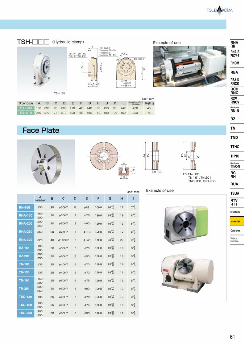
RNARNRNA-BRNCV-B
RNCM
RBA
RBA-KRNCKRCHRNCRCVRNCVMulti-Spindle
RN-N
RZ
TND
TTNC
THNC
Multi-Spindle
TTNC-N
RCRH
RUA
TSUA
RTVRTT
NC Controllers
Accessories
Options
Technical Information
TN
8-M10 Depth 20 (Equal indexing TSH-160) 8ーM12 Depth 25 (Equal indexing TSH-210)
φ40H7 Depth 15
Rc1/4(TSH-160) Rc3/8(TSH-210)
42
G
10 KφJ
φHh8
F
L CC
φE
D
22.5°
18h7 7
BA
TSH-□□□ (Hydraulic clamp)
TSH-160
Face Plate
E
F
I H
G
A Face plate diameter B C
E F
RN-100
RNA-160
135
250
25 φ50H7
30
30
φ50H7
φ75H7
30 φ60H7
φ75
φ110
φ90
φ68 10H8
12H8
G H I
16 17
19
7
19 8
200
RNA-200
RNA-250
RNA-320
250
160
200
200
160
250
200
+2 0
+2 0
+1 0
+1 0
12H8 1919 8 +2 0
+1 0
12H8 1919 8 +2 0
+1 0
320 40 φ110H7 φ140 14H8 2323 9 +2 0
+1 0
RZ-161 30 φ50H7 φ75 12H8 1919 8 +2 0
+1 0
RZ-201 30 φ60H7 φ90 12H8 1919 8 +2 0
+1 0
TN-101 135 25 φ40H7 φ70 12H8 1919 8 +2 0
+1 0
TN-131
TN-161
TN-201
135 25 φ40H7 φ70 12H8 1919 8 +2 0
+1 0
D
3
5
3
5
5
5
3
5
5
25 φ50H7 φ75200
16012H8 1919 8
+2 0
+1 05
TND-130
TND-200
135 25 φ40H7 φ70 12H8 1919 8 +2 0
+1 05
30 φ60H7 φ90200
12H8 1919 8 +2 0
+1 05
250
TND-160 25 φ50H7 φ75160
12H8 1919 8 +2 0
+1 05
200
30 φ60H7 φ90 12H8 1919 8 250
200 +2 0
+1 05
Example of use
Example of use
Unit: mm
A B C D E F G H J K L
TSH-160 160 290 70 260 110 42 142 130 150 90 142 490
TSH-210 210 370 77 310 120 45 155 150 180 100 152 833
45
75
Unit: mm
φA
φC
DB
B
φA
φC
DFor RN-100 TN-161, TN-201 TND-160, TND-200
Order Code Weight kgClamping Torque(N・ m) ( 3.5MPa)
61

RNARNRNA-BRNCV-B
RNCM
RBA
RBA-KRNCKRCHRNCRCVRNCVMulti-Spindle
RN-N
RZ
TN
TND
TTNC
THNC
Multi-Spindle
TTNC-N
RCRH
RUA
TSUA
RTVRTT
NC Controllers
Accessories
Options
Technical Information
High-precision Specification by Rotary Encoders or MP Scales
Example of measurement indexing accuracy with scale
Indexing accuracy can be upgraded by attaching a rotary encoder or MP scale to the spindle of the rotary table. The sum of the cumulative indexing accuracy of the rotary encoder or the MP scale and electrically divided errors of the pre-amplifier or the waveform shaping unit is referred to as the indexing accuracy of the rotary tables with scales. The indexing accuracy is guaranteed by TSUDAKOMA.
"RNCM-□□□R,□□"
Model Description
Rotary encoder
MP scale20sec
degrees
10
0 0 100 360
-10
Indexing accuracy with scale
RE(Rotary encoders) (MP scales) RI
Optional specifications
RNCM-251, 301RBA-250, RBA-250K
RBA-320, RBA-320K
RNA-160
RNA-200
RNA-250
RNA-320
RBA-400, RBA-400KRBA-500, RBA-500KRNCM-401~631RNCK-631RCV-800, 1000 RNCV-1201~1501
TN-161
TND-160
TN-201
TND-200
TN-320
TTNC-631
TTNC-1001
RON786, RCN727For RON886
RON786, RCN727For
RON886
RON285, RCN223F
10sec/RON786, RCN727F 6sec/RON886
RON786, RCN727For
RON886, RCN827F
10sec/RON786, RCN727F 6sec/RON886, RCN827F
RON786, RCN727For
RON886
10sec/RON786, RCN727F 6sec/RON886
10sec/RON786, RCN727F 6sec/RON886
15sec
RON285, RCN223F 15sec
MPI 736B
MPI 1072B
MPI 1272B
MPI 536A
MPI 736B
MPI 1072B
MPI 736B
MPI 736B
MPI 1272B
MPI 1272B
MPI 736B
MPI 1272B
TN-131
TND-130
TN-450
MPI 536A
Rotary encoders
Order Code Accuracy with scale Order Code Accuracy with scale
MP scales
10sec
10sec
8sec
8sec
15sec
15sec
10sec
10sec
10sec
15sec
8sec
15sec
For other accuracy standard. P.72~
Rotary axis
Rotary axis
Rotary axis
Rotary axis
Rotary axis
Rotary axis
Tilt axis
Rotary axis
Tilt axis
Rotary axis
Tilt axis
Rotary axis
Tilt axis
Rotary axis
Tilt axis
Rotary axis
Tilt axis
Rotary axis
Tilt axis
8sec
Accuracy differs depending on the specifications of the tables. Ask us for further information.
62

RNARNRNA-BRNCV-B
RNCM
RBA
RBA-KRNCKRCHRNCRCVRNCVMulti-Spindle
RN-N
RZ
TND
TTNC
THNC
Multi-Spindle
TTNC-N
RCRH
RUA
TSUA
RTVRTT
NC Controllers
Accessories
Options
Technical Information
TN
Servo motors
Servo amplifier
IBV unitEncoder
Machining CentersRotary Tables
Machining CentersRotary Tables
Encoder
IBV unit
MP scale
Servo motors
Pre-amplifier
Servo amplifier
A/D converterMP scale
Pre-amplifier
■Specifications of rotary encoders (by HEIDENHAIN)
■Specifications of MP scales (by Mitsubishi Heavy Industries)
Interface unit
Recommended resolution
Rotary Encoders RON285
IBV102
0.0001°
RON786
IBV102
0.0001°
RON886
IBV102
0.00005°
RCN223F
Not required
23bit ABS
RCN727F
Not required
27bit ABS
Note 1:
Note 2:
RCN223F and 723F are compatible with FANUC serial interfaces. Consult us for further information about NC compatible units. For single-axis NC controller TPC3-RE type, select RON886 for a rotary encoder and IBV102 for an interface unit.
Recommended resolution
A/D converter
MP scale MPI 536A MPI 736B MPI 1072B MPI 1272B
0.0001° 0.0001° 0.00005° 0.00005°
ADB-20J10
Note 1:
Note 2:
Note 3:
Use of AD converter ADB-20J60 enables serial interface connection.
Preamplifiers are necessary for MPR-series.
When using preamplifiers for MPR-series other than those of MHI Machine Tool Engineering, consult us.
63

RNARNRNA-BRNCV-B
RNCM
RBA
RBA-KRNCKRCHRNCRCVRNCVMulti-Spindle
RN-N
RZ
TN
TND
TTNC
THNC
Multi-Spindle
TTNC-N
RCRH
RUA
TSUA
RTVRTT
NC Controllers
Accessories
Options
Technical Information
オプション
Pull Stud
Rotary Joint
A unit to position and fix a fixture and a workpiece on the rotary table, by using the taper shank with a pull stud. This unit can be combined with a robot or a work loader to create an unmanned machining system.
A rotary joint unit to supply hydraulic or pneumatic pressure to workpieces or actuators mounted on rotary tables. Automatic loading and unloading of workpieces are possible.
*With clamp/unclamp confirmation switch
Jig
Work
Applicable models and specifications
Taper shankOrder CodePull stud clamp force
N【kgf】
Hydraulic pressure MPa【kgf/cm2】
Pneumatic pressure for air blow MPa【kgf/cm2】
RBA-250RBA-250K
BT-50 11,000【1,122】
3.5【35】
0.2~0.4【2~4】
3.5【35】
0.2~0.4【2~4】
15,000【1,530】
TN-201TN-320RBA-320
BT-50
RBA-320KRBA-400RBA-400KRBA-500RBA-500K
Applicable models and specifications
SizeOrder Code Max. number of portsRated supplied pressure
MPa 【kgf/cm2】
160
200
250
320
251
301
401
501
250
320
400
500
631
RNA
RNCM
RBA
6
6
6
8
6
6
6
12
8
3.5 【35】
RNCK
8
8
8
8
Pull Stud bolt
Taper
θ
RBA-320R
Optional specifications
Unit: mm
Unit: mm
P.36
RBA-320KRNCM-251R
Internal mount typeExternal mount type
Specify the pull stud type.
Pull stud type
θ 45° 60° 90°
Ⅰ Ⅱ Others
BT-50
Taper
A rotary table of the RC series, equipped with 8 port rotary joints as standard features can be used as well.
64
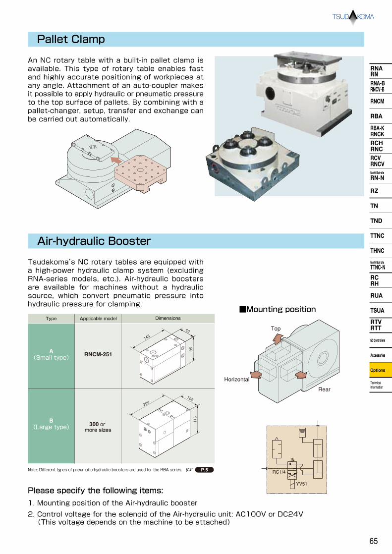
RNARNRNA-BRNCV-B
RNCM
RBA
RBA-KRNCKRCHRNCRCVRNCVMulti-Spindle
RN-N
RZ
TND
TTNC
THNC
Multi-Spindle
TTNC-N
RCRH
RUA
TSUA
RTVRTT
NC Controllers
Accessories
Options
Technical Information
TN
Pallet Clamp
Air-hydraulic Booster
An NC rotary table with a built-in pallet clamp is available. This type of rotary table enables fast and highly accurate positioning of workpieces at any angle. Attachment of an auto-coupler makes it possible to apply hydraulic or pneumatic pressure to the top surface of pallets. By combining with a pallet-changer, setup, transfer and exchange can be carried out automatically.
Tsudakoma’s NC rotary tables are equipped with a high-power hydraulic clamp system (excluding RNA-series models, etc.). Air-hydraulic boosters are available for machines without a hydraulic source, which convert pneumatic pressure into hydraulic pressure for clamping.
95
60
145
200
146
100
Top
Horizontal
Rear
RC1/4
YV51
Applicable modelType Dimensions
RNCM-251
300 or more sizes
A(Small type)
B(Large type)
Note: Different types of pneumatic-hydraulic boosters are used for the RBA series.
Please specify the following items:
1. Mounting position of the Air-hydraulic booster
2. Control voltage for the solenoid of the Air-hydraulic unit: AC100V or DC24V (This voltage depends on the machine to be attached)
■Mounting position
P.5
65

RNARNRNA-BRNCV-B
RNCM
RBA
RBA-KRNCKRCHRNCRCVRNCVMulti-Spindle
RN-N
RZ
TN
TND
TTNC
THNC
Multi-Spindle
TTNC-N
RCRH
RUA
TSUA
RTVRTT
NC Controllers
Accessories
Options
Technical Information
Explanation of Technical Terms
In order to help you understand Tsudakoma's products, here are some explanations about the main specifications.
Indexing AccuracyAfter indexing one rotation of the table equally according to the tooth number of the worm gear, obtain the difference between the theoretical turning angle and the measured angle. The indexing accuracy is the sum of the maximum difference in positive values and that in negative values (absolute values).
RepeatabilityIndexing at four specified angles (0, 90, 180 and 270 degrees) is carried out five times for clockwise rotation to measure the indexing angle. Then, the difference between the minimum and maximum values measured at each angular position is obtained. Carry out indexing for counterclockwise rotation in the same manner as the above, and obtain the difference between the minimum and maximum values measured at each angular position. The maximum value of the difference obtained through both measurements is the repeatability of the table.
Clamp TorqueClamp torque is only the force of the clamping mechanism, which does not include force caused by self-locking of a worm gear. The clamp torque shown in the catalog is the figure obtained when the rated pressure (3.5 MPa for hydraulic pressure, and 0.49 MPa for pneumatic pressure) is supplied to the working fluid. When a larger clamp torque is required, increase the pressure gradually up to the maximum allowable pressure (4.9 MPa for hydraulic pressure, 0.69 MPa for pneumatic pressure) to increase the clamp torque.
Worm Gear StrengthWorm gear strength is the allowable wheel torque when table rpm is 1 min-1. The allowable torque for the worm wheel is calculated according to the standards stipulated by the Japan Gear Manufactures Association.
Table Turning Angle and Indexing Measurement Data
Table Turning Angle (deg)
4
2
0
- 2
- 4
- 6
- 8
-10
-12
Indexin
g M
easurement D
ata
(sec
)
Max. difference of negative value
Indexin
g accuracy
Max. difference of positive value
180 270 36090
Technical Information
66

RNARNRNA-BRNCV-B
RNCM
RBA
RBA-KRNCKRCHRNCRCVRNCVMulti-Spindle
RN-N
RZ
TND
TTNC
THNC
Multi-Spindle
TTNC-N
RCRH
RUA
TSUA
RTVRTT
NC Controllers
Accessories
Options
Technical Information
TN
FANUC αi type servo motors are specified for each NC table model in the specifications table. The table below shows other servo motors, which have equivalent capacity to those of FANUC αi motors.
Applicable Servo Motors
FANUC
MITSUBISHI
YASKAWA
αiF2/5000
(αiS2/5000)
HA33NC-TS
(HF75T)
SGMPH-04
αiF4/4000
(αiS4/5000)
HC52T
(HF54T)
SGMGH-05
αiF8/3000
(αiS8/4000)
HC102T
(HF104T)
SGMGH-09
αiF12/3000
(αiS12/4000)
HC202S
(HF204S)
SGMGH-20
αiF22/3000
(αiS22/4000)
HC352S
(HF354S)
SGMGH-30
OKUMA BL-ME24J BL-ME40J BL-ME80J BL-ME150J BL-ME200J
SIEMENS 1FT6044 1FT6061 1FT6062 1FT6082 1FT6084
HEIDENHAIN QSY96G QSY116C QSY116E QSY155B QSY155D
Applicable Cable Connectors
All cable plugs and connectors for Tsudakoma's NC rotary tables should be waterproof. Refer to the table below.
Plug Connector
Flexible tube
For signal cable
For power cable
Rotary table receptacle
N/MS3102A20-29PW (Japan Aviation Electronics Industry, Ltd.)
N/MS3102A22-14 (Japan Aviation Electronics Industry, Ltd.)
N/MS3102A28-11P (Japan Aviation Electronics Industry, Ltd.)
Cable plug
JA06A20-29SW-J1-R (Japan Aviation Electronics Industry, Ltd.)
JA06A22-14S-J1-R (Japan Aviation Electronics Industry, Ltd.)
JA06A28-11S-J1-R (Japan Aviation Electronics Industry, Ltd.)
Flexible tube
KPF-22(SANKEI MANUFACTURING CO.,LTD) FCV-22(DAIWA DENGYO CO.,LTD)
FCV-28 (DAIWA DENGYO CO.,LTD)
Connector
KMKD22-20(SANKEI MANUFACTURING CO.,LTD) MSA22-20(DAIWA DENGYO CO.,LTD)
KMKD22-22(SANKEI MANUFACTURING CO.,LTD) MSA22-22(DAIWA DENGYO CO.,LTD)
KMKD28-28(SANKEI MANUFACTURING CO.,LTD) MSA28-28(DAIWA DENGYO CO.,LTD)
Example of cable plug connectors
For signal cable
For power cable
Rotary table receptacle
N/MS3102A20-29PW (Japan Aviation Electronics Industry, Ltd.)
JL04V-2A28-11PE-R (Japan Aviation Electronics Industry, Ltd.)
Cable plug
JA06A20-29SW-J1-R (Japan Aviation Electronics Industry, Ltd.)
JL04V-6A28-11SE-R (Japan Aviation Electronics Industry, Ltd.)
Flexible tube
NSBS#20 (SANKEI MANUFACTURING CO.,LTD)
NSBS#32 (SANKEI MANUFACTURING CO.,LTD)
Connector
NBKD-20-20 (SANKEI MANUFACTURING CO.,LTD)
NBKD-32-28 (SANKEI MANUFACTURING CO.,LTD)
Example of cable plug connectors (with a FANUC αiF motor)
Note: JA064□□ plug is waterproof when the plug is inserted.
P.77
Note 1: Some motors have speed reduction ratio (max rpm) or outline dimensions different from those of FANUC motors. Note 2: The motors shown above are classified according to motor torque capacity. The motor which is suitable for your machines depends
on the specifications of your machine NC controllers. Consult the machine manufacturer about motor selection.
67

RNARNRNA-BRNCV-B
RNCM
RBA
RBA-KRNCKRCHRNCRCVRNCVMulti-Spindle
RN-N
RZ
TN
TND
TTNC
THNC
Multi-Spindle
TTNC-N
RCRH
RUA
TSUA
RTVRTT
NC Controllers
Accessories
Options
Technical Information
Flow Chart of Control System
Indexing Cycle Time
Positioning starts
Unclamp command
Clamp LS OFF?
Unclamp LS ON?
250ms delay
Table rotating command
Check positioning completion
250ms delay
Clamp command
Unclamp LS OFF?
Clamp LS ON?
Yes
Yes
Yes
Yes
Yes
No
No
No
No
No
Positioning starts
Servo ON
Unclamp command
Clamp LS OFF?
Unclamp LS ON?
250ms delay
Table rotating command
Check positioning completion
250ms delay
Clamp command
Unclamp LS OFF?
Clamp LS ON?
500ms delay
Servo OFF
Positioning completed
Yes
Yes
Yes
Yes
Yes
No
No
No
No
No
a)Semi-closed loop control b)Fully-closed loop control
0
1
2
0
3
4
5
6(sec)
30 60 90 120 150 180 210 240 270 300 330 360Indexing angle (deg)
AB
C
D
0
1
2
0
3
4
5
6(sec)
30 60 90 120 150 180 210 240 270 300 330 360Indexing angle (deg)
A
B
C
D
Table rpm 8000deg/min(22.2min-1) Acceleration/deceleration constant:150ms
Table rpm 12000deg/min(33.3min-1) Acceleration/deceleration constant:150ms
Note: For the above B and C cases, the indexing time includes the time to respond to the clamp and unclamp confirmation signals.
:Without clamp command
:For hydraulic clamp(0.4Sec)
:For pneumatic clamp(0.6Sec)
:For air-hydraulic clamp(1.0Sec)
A
B
C
D
Technical Information
Positioning completed
Note 3:
Note 3:
Note 3:
Note 3:
Note 3:
It is recommended to control Tsudakoma's NC rotary table with the servo motor ON. The following are recommended flow charts.
The graphs below show the required indexing time which includes the time for the control command for the machine tools. This information helps you examine the cycle time of your process with the rotary table. Table rotation speed and acceleration and deceleration constants may differ depending on the model of the rotary table. If any data other than that shown below is required, please ask us.
In a semi-closed loop control operation, do not turn the Servo motor OFF even when the rotary table is clamped. In a semi-closed operation, when the eccentric load increases in size, and a large current (70% or more of the rated current) is being applied, turn the Servo motor OFF and follow the steps for the full-closed loop control. Delay time is our recommended time. Parameters may differ depending on the specifications. Ask us for further information.
Note 1: Note 2: Note 3:
Required indexing time (sec)
Required indexing time (sec)
※( )shows Clamp & Un-clamp reguired time
68

RNARNRNA-BRNCV-B
RNCM
RBA
RBA-KRNCKRCHRNCRCVRNCVMulti-Spindle
RN-N
RZ
TND
TTNC
THNC
Multi-Spindle
TTNC-N
RCRH
RUA
TSUA
RTVRTT
NC Controllers
Accessories
Options
Technical Information
TN
Workpiece mounting space for tilting rotary table
Note 1: If the tilting angle is over the above range or the table stops by emergency stop, check the unit. Note 2: Be sure to remove the eye bolts used for lifting before using the rotary table.
TN-161
TN-131
TN-101
TN-201
TN-320
TN-450
0~+90° 0~+107° -17°~0
0~+90° 0~+107° -17°~0
0~+90° 0~+110° -30°~0
0~+90° 0~+110° -30°~0
0~+90° 0~+110° -30°~0
-10°~+95° -15°~+100°
3090 110
φ490φ440φ374φ354 φ354
45 65
φ260φ160φ150
17°
169
φ140
φ150
5010
φ280φ180φ150
180
17° φ150
10
φ180φ150
125
65
φ650φ530φ500
20°
20°
505
360
170
125
65
φ650φ530φ512φ500
20°
175
φ320
TND-130
0~+90° 0~+107° -17°~0
80
φ200φ350 20°
φ200
175
φ200
φ250
100130
φ250φ360φ400
20°
100 210
φ230φ250
TND-160
0~+90° 0~+110° -30°~0
φ250
85
φ200
20°
20°
160
85
φ250
φ200
φ410φ250φ200
5085
TND-200
0~+90° 0~+110° -30°~0
φ220φ170
55
55195
17° 17°
φ220φ170
6555
φ360φ220φ170
φ300φ250
65
φ300
φ250
20° 20°
250
65
115
65
φ500φ300φ250
※Emergency stop angleLoading area is set taking the inertia of 10° from the emergency stop position into consideration.
69
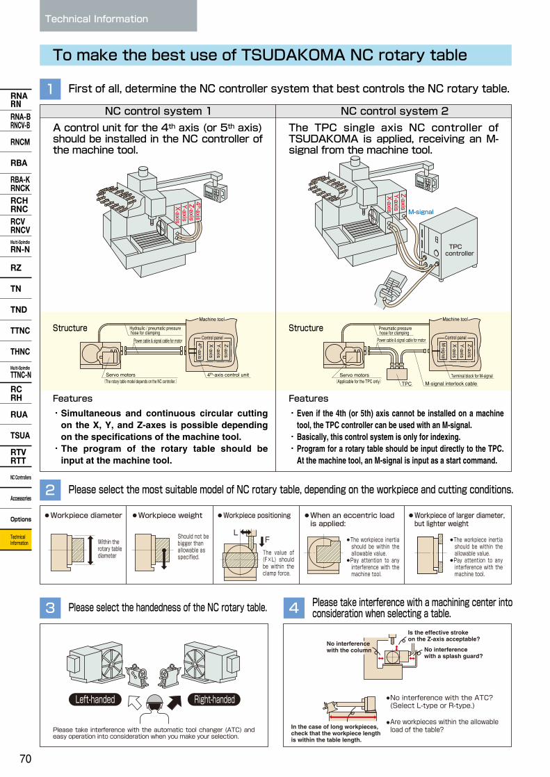
RNARNRNA-BRNCV-B
RNCM
RBA
RBA-KRNCKRCHRNCRCVRNCVMulti-Spindle
RN-N
RZ
TN
TND
TTNC
THNC
Multi-Spindle
TTNC-N
RCRH
RUA
TSUA
RTVRTT
NC Controllers
Accessories
Options
Technical Information
To make the best use of TSUDAKOMA NC rotary table
First of all, determine the NC controller system that best controls the NC rotary table.1
Please select the most suitable model of NC rotary table, depending on the workpiece and cutting conditions.2
Please select the handedness of the NC rotary table.3 Please take interference with a machining center into consideration when selecting a table.4
NC control system 1
Structure Structure
Features Features
NC control system 2
Servo motors
Control panel
Machine tool
Hydraulic / pneumatic pressure hose for clamping
Power cable & signal cable for motor
(The rotary table model depends on the NC controller.) 4th-axis control unit
Z軸
Y軸
X軸
TPC
TPC
コントロ
ーラ
M-signal
TPC controller
Pneumatic pressure hose for clampingPower cable & signal cable for motor
(Applicable for the TPC only) Servo motors Terminal block for M-signal
M-signal interlock cableTPC
Workpiece diameter When an eccentric load is applied:
Workpiece of larger diameter, but lighter weight
Workpiece weight Workpiece positioning
LF
Left-handed Right-handed
Is the effective stroke on the Z-axis acceptable?
No interference with a splash guard?
No interference with the column
In the case of long workpieces, check that the workpiece length is within the table length.
No interference with the ATC? (Select L-type or R-type.) Are workpieces within the allowable load of the table?
Technical Information
A control unit for the 4th axis (or 5th axis) should be installed in the NC controller of the machine tool.
The TPC single axis NC controller of TSUDAKOMA is applied, receiving an M-signal from the machine tool.
4th-axis
X-axisY-axisZ-axis
4th-axis
X-axis
Y-axisZ-axis
X-axis
Y-axisZ-axis
・Simultaneous and continuous circular cutting on the X, Y, and Z-axes is possible depending on the specifications of the machine tool.
・The program of the rotary table should be input at the machine tool.
・Even if the 4th (or 5th) axis cannot be installed on a machine tool, the TPC controller can be used with an M-signal.
・Basically, this control system is only for indexing. ・Program for a rotary table should be input directly to the TPC.
At the machine tool, an M-signal is input as a start command.
Control panel
X-axis
M-signal
Y-axisZ-axis
Within the rotary table diameter
Should not be bigger than allowable as specified.
The value of (F×L) should be within the clamp force.
・The workpiece inertia should be within the allowable value.
・Pay attention to any interference with the machine tool.
・The workpiece inertia should be within the allowable value.
・Pay attention to any interference with the machine tool.
Please take interference with the automatic tool changer (ATC) and easy operation into consideration when you make your selection.
Machine tool
70

RNARNRNA-BRNCV-B
RNCM
RBA
RBA-KRNCKRCHRNCRCVRNCVMulti-Spindle
RN-N
RZ
TND
TTNC
THNC
Multi-Spindle
TTNC-N
RCRH
RUA
TSUA
RTVRTT
NC Controllers
Accessories
Options
Technical Information
TN
If you need our help to select the best model for you:
Inform TSUDAKOMA of the information below, and TSUDAKOMA will suggest the best model for you.
1. Customer
Tel
2. Model considering Unit
3. Machine Manufacturer
Model (New ・ Installed)
NC controller
Not used Used(Oil ・ Water) (Normal ・ High Pressure)
Kind
Dimensions Height × Length( ) ( ) × Width mm
mm
( )
Inner dia × Outer dia( ) ( ) × Length( )
4. Coolant oil
5. Workpiece
6. Layout of workpiece and fixture (Write the detailed dimensions from the top surface or the center of the face plate)
7. Cutting conditions
Fill in this page and send it to a local distributor or TSUDAKOMA. Fax:+81-76-294-5157
Material Weight
Cutting point Cutter / teeth number
Cutting speed (V)
Cutting feed rate mm/min
Cutting depth mm/time
Cutting process (Indexing or continuous cutting)
a
b
c
d
Example
71

RNARNRNA-BRNCV-B
RNCM
RBA
RBA-KRNCKRCHRNCRCVRNCVMulti-Spindle
RN-N
RZ
TN
TND
TTNC
THNC
Multi-Spindle
TTNC-N
RCRH
RUA
TSUA
RTVRTT
NC Controllers
Accessories
Options
Technical Information
Inspection Standard
NC Rotary Tables
1 2 3
5 6 7 8
9
4
0.010.020.01
±0.020.02
25 15 20 15 20 10 20 10
ToleranceRNA-160
0.010.020.01
±0.020.02
0.02 0.02
RNA-200 RNA-320
0.010.020.01
±0.020.02
0.02
RNA-250Inspection items
Spindle end runout
Parallelism of spindle end to frame bottom
Center bore runout
Perpendicularity of spindle end to frame bottom
Perpendicularity of spindle end to frame bottom guide
Indexing accuracy(arc sec.)
Parallelism of center line between rotary table and tailstock to frame bottom guide blocks
No.
234567
8
Inspection items
Spindle end runout
Parallelism of spindle end to frame bottom
Center bore runout
Perpendicularity of spindle end to frame bottom
Perpendicularity of spindle end to frame bottom guide
Indexing accuracy(arc sec.)
Height difference of both center lines of rotary table and tailstock
2
No.
345679
Technical Information
単位: mm
0.01
8
Table top flatness (0.01 convex permissible)
Table top runout
Parallelism of table top to frame bottom
Center bore runout
Perpendicularity of table top to frame bottom
Perpendicularity of table top to frame bottom guide blocks
Indexing accuracy(arc sec.)
Parallelism of center line between rotary table and tailstock to frame bottom guide blocks
Height difference of both center lines of rotary table and tailstock (tailstock center line should be higher)
1234567
8
9
0.030.020.030.010.030.0315
0.02
0.02
0.020.010.02
0.020.038
0.02
0.02
0.040.030.040.010.040.04
0.02
0.02
0.020.020.020.010.030.03
15
0.040.030.040.010.040.04
0.03
0.04
15
0.040.030.040.010.040.04
0.03
0.04
15
0.02
0.02
RNCV-1201Standard Standard
RNCV-1501
Note: The indexing accuracy above is for tables with MP scales. See for indexing accuracy of HEIDENHAIN rotary encoders.
±0.03 ±0.03 ±0.03
0.010.020.01
±0.020.02
0.02
±0.03Height difference of both center lines of rotary table and tailstock9
Per 200mm
Spindle nose
Per 200mm
Per 300mm
Per overall length
Cumulative
Per overall length
Spindle nose
Per overall length
Per overall length
Cumulative
Horizontal
Vertical
Vertical
Vertical
Per overall length
Per overall length
Spindle nose
Per overall length
Per overall length
Cumulative
Per 300mm
Horizontal
Vertical
Vertical
Vertical
Vertical
Horizontal
Vertical
Vertical
Vertical
Vertical
Cylindrical
Unit: mm
Unit: mm
Note: The indexing accuracy above is for tables with MP scales. See for indexing accuracy of HEIDENHAIN rotary encoders.
Standard With a scale Standard With a scale Standard With a scale Standard With a scale
Indexing accuracy is measured by an optical measuring device.
ToleranceInspection itemsNo.
Standard With a scale Standard With a scale
P.62
P.62
0.010.0150.01
±0.020.0245
ToleranceRN-100
±0.03
Unit: mm
0.0150.020.015
±0.020.0245
RZ-1610.0150.020.02
±0.020.0245
±0.03 ±0.03
RZ-201
RCV-800 RCV-1000
、
、
72

RNARNRNA-BRNCV-B
RNCM
RBA
RBA-KRNCKRCHRNCRCVRNCVMulti-Spindle
RN-N
RZ
TND
TTNC
THNC
Multi-Spindle
TTNC-N
RCRH
RUA
TSUA
RTVRTT
NC Controllers
Accessories
Options
Technical Information
TN
単位: mm
0.010.0150.020.010.020.02
RNCM-251,301 RNCM-401,501 RNCM-631
150.020.02
0.010.010.010.0050.010.01100.010.01
0.020.0150.020.010.020.02150.020.02
0.010.010.010.0050.010.0180.010.01
0.030.020.030.010.030.03150.020.02
0.010.010.020.010.020.0380.020.02
Table top flatness (0.01 convex permissible)
Table top runout
Parallelism of table top to frame bottom
Center bore runout
Perpendicularity of table top to frame bottom
Perpendicularity of table top to frame bottom guide blocks
Indexing accuracy(arc sec.)
Parallelism of center line between rotary table and tailstock to frame bottom guide blocks
Height difference of both center lines of rotary table and tailstock (tailstock center line should be higher)
123456789
Note: The indexing accuracy above is for tables with MP scales. See for indexing accuracy of HEIDENHAIN rotary encoders.
0.030.020.010.030.03
ToleranceRNCK-631
150.020.02
0.020.010.0050.020.0380.020.02
Table top flatness (0.01 convex permissible)
Table top runout
Center bore runout
Perpendicularity of table top to frame bottom
Perpendicularity of table top to frame bottom guide blocks
Indexing accuracy(arc sec.)
Parallelism of center line between rotary table and tailstock to frame bottom guide blocks
Height difference of both center lines of rotary table and tailstock (tailstock center line should be higher)
12456789
Note: The indexing accuracy above is for tables with MP scales. See for indexing accuracy of HEIDENHAIN rotary encoders.
ToleranceRBA-250,320 RBA-250K,320K
RBA-400,500 RBA-400K,500K
0.010.010.010.0050.010.018(10) 0.010.01
0.020.0150.020.010.020.02140.020.02
Table top flatness (0.01 convex permissible)
Table top runout
Parallelism of table top to frame bottom
Center bore runout
Perpendicularity of table top to frame bottom
Perpendicularity of table top to frame bottom guide blocks
Indexing accuracy(arc sec.)
Parallelism of center line between rotary table and tailstock to frame bottom guide blocks
Height difference of both center lines of rotary table and tailstock (tailstock center line should be higher)
123456789
Note 1: The indexing accuracy above is for tables with MP scales. See for indexing accuracy of HEIDENHAIN rotary encoders. Note 2: For RBA-K, No. 3 is not required. Note 3: The figures in ( ) above show an indexing accuracy with scale for the RBA-250 and RBA-250K.
Horizontal
Vertical
Vertical
Vertical
Vertical
Per overall length
Per overall length
Spindle nose
Per overall length
Per overall length
Cumulative
Per 300mm
Per overall length
Spindle nose
Per overall length
Per overall length
Cumulative
Per 300mm
Per overall length
Per overall length
Spindle nose
Per overall length
Per overall length
Cumulative
Per 300mm
Horizontal
Vertical
Vertical
Vertical
Vertical
Unit: mm
Unit: mm
Unit: mm
ToleranceInspection itemsNo.
Inspection itemsNo.
Standard With a scale
Standard With a scale
Inspection itemsNo.
0.010.0150.020.010.020.02140.020.02
Standard With a scale Standard
0.010.010.010.0050.010.0180.010.01
With a scale
Standard With a scale Standard With a scale
P.62
P.62
P.62
、
単位: mm
0.030.020.030.01
RCH-800 RCH-1000,1201,1501 RNC-2001
15
0.020.010.020.018
0.040.030.040.0115
0.020.020.020.018
0.040.030.040.0115
0.030.020.030.018
Table top flatness (0.01 convex permissible)
Table top runout
Parallelism of table top to frame bottom
Center bore runout
Indexing accuracy(arc sec.)
12347
Note: The indexing accuracy above is for tables with MP scales.
Per overall length
Per overall length
Spindle nose
Cumulative
Unit: mm
ToleranceInspection itemsNo.
Standard With a scale Standard With a scale Standard With a scale
、
73

RNARNRNA-BRNCV-B
RNCM
RBA
RBA-KRNCKRCHRNCRCVRNCVMulti-Spindle
RN-N
RZ
TN
TND
TTNC
THNC
Multi-Spindle
TTNC-N
RCRH
RUA
TSUA
RTVRTT
NC Controllers
Accessories
Options
Technical Information
資料
Inspection Standard
NC Rotary Tables
NC Rotary Table / Multi-Spindle
1 2 3
5 6 7
9 10
4
8
Technical Information
0.0150.01600.020.020.02
Vertical
Vertical
Vertical
Vertical
Vertical
Horizontal
Horizontal
ToleranceRN-100-N
0.020.030.0150.02
0.0150.015300.020.020.02
RN-150-N
0.020.020.020.02
0.0150.02300.020.020.02
RN-200-N
0.020.020.020.02
0.020.02300.020.030.02
RN-250-N 300-N
0.020.020.030.02
Inspection items
Table top runout
Center bore runout
Indexing accuracy(arc sec.)
Squareness between table top and base plate
Parallelism and perpendicularity of the table top to base bottom guide blocks
Difference between both center heights
Difference of the distance between base bottom guide block and table top
Height difference of both center lines of rotary table and tailstock
Parallelism of the table top to base bottom
Difference among the average heights between base bottom and table top
1
No.
2345678910
0.030.020.030.02
ToleranceRC-250,300,400,500
25
Inspection items
Table top flatness (High top at the center by 0.01mm is acceptable)
Table top runout
Parallelism of table top to frame bottom
Center bore runout
Indexing accuracy(arc sec.)
1
No.
2347
Note 1: For the RN-100-N,RN-150-N and RN-200-N, all the descriptions of “table top” seen in the inspection items should be “spindle end surface”. Note 2: If the base has no guide block, “base bottom guide block” in the above instructions (Nos. 5 and 7) should be construed as “base bottom”.
Per overall length
Per overall length
Spindle nose
Cumulative
Cumulative
Spindle nose
Per overall length
Per overall length
Per overall length
Cylindrical
Unit: mm
Unit: mm
Indexing accuracy is measured by an optical measuring device.
0.03 0.02 0.02 0.03 30
Per overall length
Per overall length
Spindle nose
Cumulative
ToleranceRUA-250
0.03 0.02 0.02 0.03 30
RUA-3200.03 0.02 0.02 0.03 25
RUA-4000.03 0.02 0.02 0.03 25
RUA-500Inspection items
Table top flatness (High top at the center by 0.01mm is acceptable)
Table top runout
Center bore runout
Perpendicularity of table top to frame bottom
Indexing accuracy(arc sec.)
1
No.
2457
Unit: mm
74

RNARNRNA-BRNCV-B
RNCM
RBA
RBA-KRNCKRCHRNCRCVRNCVMulti-Spindle
RN-N
RZ
TND
TTNC
THNC
Multi-Spindle
TTNC-N
RCRH
RUA
TSUA
RTVRTT
NC Controllers
Accessories
Options
Technical Information
TN
NC Tilting Rotary Tables
1 2 3
5 6・7
4
単位: mm
ー ー ー ー 0.010.0150.020.015
45
TN-101Standard Standard Standard Standard Standard Standard
TN-131 TN-161 TN-201 TN-320 TN-450
ー ー
400.015
0.010.0150.020.015
45(15)
40(15) 0.015
0.010.0150.020.015
4560
300.015
0.010.0150.020.015
4560
300.015
0.010.0150.020.020.01
4560
200.02
0.020.0150.020.020.01
90ー
150.02
Table top flatness (0.01 convex permissible)
Table top runout
Parallelism of table top to frame bottom
Parallelism of tilt axis center to frame bottom
Center bore runout
Tilting accuracy(arc sec.)
Indexing accuracy(arc sec.)
Perpendicularity of table top to frame bottom guide blocks (Parallelism)
12345
6
78
Note 1: For item 8, values differ depending on the mounting direction of the guide block. Note 2: The table tops of TN-101 and TN 131, are the ends of the spindles. Note 3: Values in ( ) for TN-131 are accuracy for tables with rotary encoders and MP scales for high precision.
Per overall length
Per overall length
Per overall length
Spindle nose
Cumulative(0°~+90°) Cumulative(ー30°~+90°)
Cumulative
Per overall length(90 degree)
8
Unit: mm
ToleranceInspection itemsNo.
Tilt ing angle and indexing accuracy are measured by means of optical equipment.
P.62
P.62
Table top flatness (0.01 convex permissible)
Table top runout
Parallelism of table top to frame bottom
Parallelism of tilt axis center to frame bottom
Center bore runout
Tilting accuracy(arc sec.)
Indexing accuracy(arc sec.)
Perpendicularity of table top to frame bottom guide blocks (Parallelism)
Note 1: For item 8, values differ depending on the mounting direction of the guide block. Note 2: "Table Top" means "the End of Spindle".
Note 1: The indexing accuracy above is for tables with MP scales. See for indexing accuracy of HEIDENHAIN rotary encoders. Note 2: For item 8, values differ depending on the mounting direction of the guide block.
Per overall length
Per overall length
Per overall length
Spindle nose
0°~+90°
Cumulative
Per overall length(90 degree)
ToleranceTTNC-631
Standard With a scaleTTNC-1001
Standard With a scale
0.020.030.030.0160150.02
0.020.030.030.011580.02
0.040.030.040.040.0160150.02
0.040.03 0.030.030.040.040.011580.02
Inspection items
1
No.
2345678
0.0150.020.020.0160
THNC-251,301Standard With a scale
150.02
0.0150.020.020.0160100.02
0.01 0.01
Per overall length
Per overall length
Per overall length
Spindle nose
Cumulative(0°~+90°) Cumulative(ー30°~+90°)
Cumulative
Per overall length(90 degree)
Inspection items
Table top flatness (0.01 convex permissible)
Table top runout
Parallelism of table top to frame bottom
Parallelism of tilt axis center to frame bottom
Center bore runout
Tilting accuracy(arc sec.)
Indexing accuracy(arc sec.)
Perpendicularity of table top to frame bottom guide blocks (Parallelism)
1
No.
2345
6
78
0.010.0150.020.01560
ToleranceTND-130Standard
TND-200Standard
ー 90400.015
0.01ー ー
0.0150.020.01575
300.015
TND-160Standard
90
0.01ー
0.0150.020.01575
300.015
Unit: mm
Unit: mm、
75

RNARNRNA-BRNCV-B
RNCM
RBA
RBA-KRNCKRCHRNCRCVRNCVMulti-Spindle
RN-N
RZ
TN
TND
TTNC
THNC
Multi-Spindle
TTNC-N
RCRH
RUA
TSUA
RTVRTT
NC Controllers
Accessories
Options
Technical Information
Inspection Standard
NC Tilting Rotary Tables / Multi-Spindle
1 2 3
5 6
9 10
4
7 8
11 12
Technical Information
0.0150.020.020.0150.02
TTNC-102-2
0.0154540
±0.020.020.015
ー Table top flatness(0.01 convex permissible)
Table top runout
Difference between average heights of both tables
Difference between distances between frame standard face and both table tops
Parallelism of table top to frame bottom
Parallelism of tilt axis center to frame bottom
Center bore runout
Tilting accuracy(arc sec.)
Indexing Accuracy(arc sec.)
123456789
Table center distance10Difference between both center heights11Perpendicularity of table top to frame bottom guide blocks(Parallelism) 12
0.0150.020.020.0150.02
TTNC-101-4
0.016060
±0.020.020.015
ー 0.0150.020.020.020.02
TTNC-151-2
0.016030
±0.020.020.02
0.020.0150.020.020.020.02
TTNC-201-2
0.016020
±0.020.020.02
0.01
Note 1: For the TTNC-102 and TTNC-101-4, all the descriptions of “table top” seen in the inspection items above should be “spindle end surface”. Note 2: For item 12, values differ depending on the mounting direction of the guide block.
Per overall length
0 degree
90 degree
Per overall length
Per overall length
Spindle nose
0°~+90°
Cumulative
90 degree
Per overall length(90 degree)
Unit: mm
Indexing accuracy is measured by an optical measuring device.
T i l t accuracy is measured using an optical scale.
ToleranceInspection itemsNo.
Machine tool attachments such as machine vises, indexers and NC rotary tables are manufactured in Tsudakoma Nonoichi plant. Tsudakoma has been a pioneer in the production of NC rotary tables, since 1930, boasting the world's largest production.
76
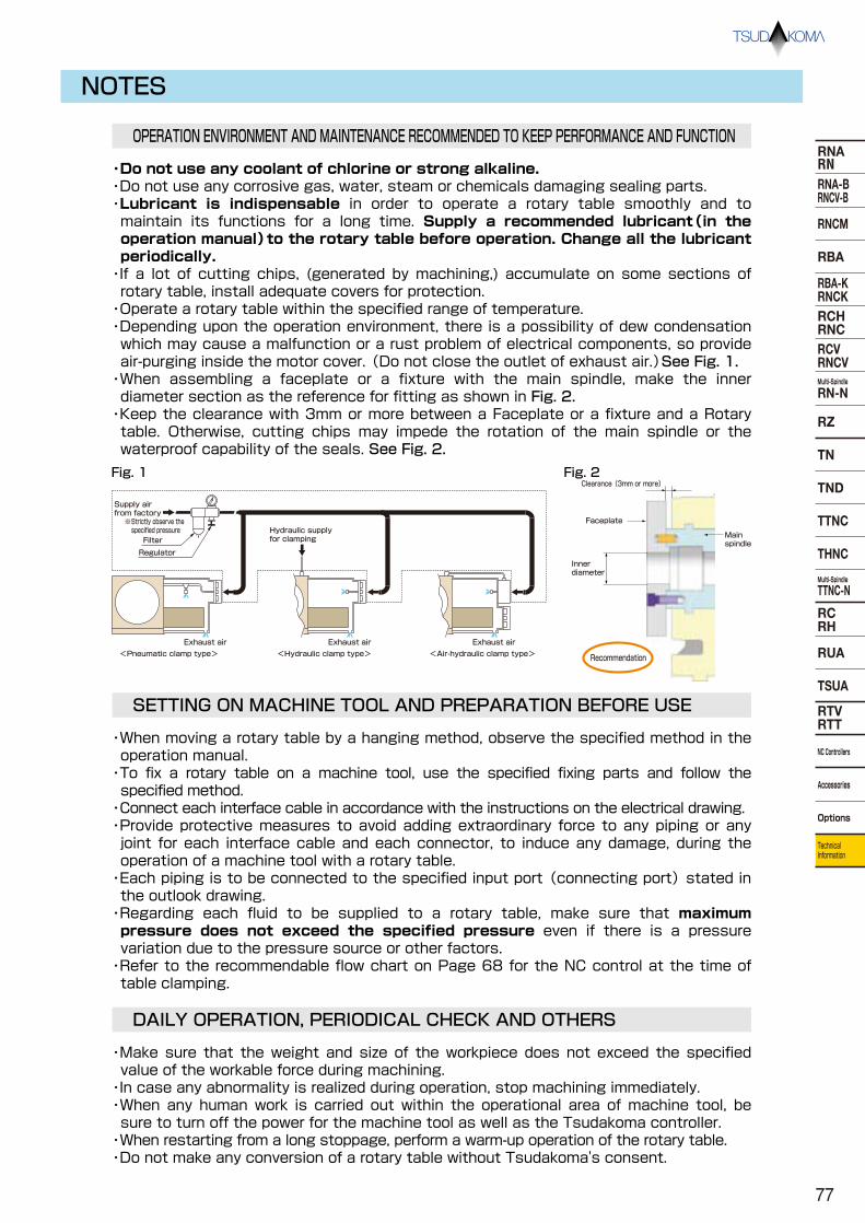
NOTES
OPERATION ENVIRONMENT AND MAINTENANCE RECOMMENDED TO KEEP PERFORMANCE AND FUNCTION
SETTING ON MACHINE TOOL AND PREPARATION BEFORE USE
・When moving a rotary table by a hanging method, observe the specified method in the operation manual. ・To fix a rotary table on a machine tool, use the specified fixing parts and follow the specified method. ・Connect each interface cable in accordance with the instructions on the electrical drawing. ・Provide protective measures to avoid adding extraordinary force to any piping or any joint for each interface cable and each connector, to induce any damage, during the operation of a machine tool with a rotary table. ・Each piping is to be connected to the specified input port (connecting port) stated in the outlook drawing. ・Regarding each fluid to be supplied to a rotary table, make sure that maximum pressure does not exceed the specified pressure even if there is a pressure variation due to the pressure source or other factors. ・Refer to the recommendable flow chart on Page 68 for the NC control at the time of table clamping.
DAILY OPERATION, PERIODICAL CHECK AND OTHERS
・Make sure that the weight and size of the workpiece does not exceed the specified value of the workable force during machining. ・In case any abnormality is realized during operation, stop machining immediately. ・When any human work is carried out within the operational area of machine tool, be sure to turn off the power for the machine tool as well as the Tsudakoma controller. ・When restarting from a long stoppage, perform a warm-up operation of the rotary table. ・Do not make any conversion of a rotary table without Tsudakoma's consent.
・Do not use any coolant of chlorine or strong alkaline. ・Do not use any corrosive gas, water, steam or chemicals damaging sealing parts. ・Lubricant is indispensable in order to operate a rotary table smoothly and to maintain its functions for a long time. Supply a recommended lubricant(in the operation manual)to the rotary table before operation. Change all the lubricant periodically. ・If a lot of cutting chips, (generated by machining,) accumulate on some sections of rotary table, install adequate covers for protection. ・Operate a rotary table within the specified range of temperature. ・Depending upon the operation environment, there is a possibility of dew condensation which may cause a malfunction or a rust problem of electrical components, so provide air-purging inside the motor cover. (Do not close the outlet of exhaust air.)See Fig. 1. ・When assembling a faceplate or a fixture with the main spindle, make the inner diameter section as the reference for fitting as shown in Fig. 2. ・Keep the clearance with 3mm or more between a Faceplate or a fixture and a Rotary table. Otherwise, cutting chips may impede the rotation of the main spindle or the waterproof capability of the seals. See Fig. 2.
※Strictly observe the specified pressure
<Pneumatic clamp type> <Hydraulic clamp type> <Air-hydraulic clamp type>
Supply air from factory
Hydraulic supply for clamping
Exhaust air Exhaust air Exhaust air
Regulator
Filter
Inner diameter
Main spindle
Faceplate
Clearance(3mm or more) Fig. 1 Fig. 2
Recommendation
77
RNARNRNA-BRNCV-B
RNCM
RBA
RBA-KRNCKRCHRNCRCVRNCVMulti-Spindle
RN-N
RZ
TND
TTNC
THNC
Multi-Spindle
TTNC-N
RCRH
RUA
TSUA
RTVRTT
NC Controllers
Accessories
Options
Technical Information
TN

NE11-12H2012-12
This catalog was printed in vegetable oil ink, using the environmentally friendly waterless offset printing process.
Overseas Distributors
Nonoichi Plant 5-100 Awada, Nonoichi, Ishikawa 921-8529 Japan Phone:+81-76-294-5111 Fax:+81-76-294-5157 http://www.tsudakoma.co.jp E-mail:[email protected]
●This catalog includes strategic items prescri-bed in the Japanese Foreign Exchange and Foreign Trade Act. In order to export such items, permissions must be obtained in accor-dance with the aforementioned law.
U.S.A.
FRANCE
TAIWAN
GERMANY
SPAIN
KOREA
ITALY
INDIA
CHINA
KOMA PRECISION, INC. Address: 20 Thompson Road, East Windsor, CT 06088 Tel: +1 860 627 7059 Fax: +1 860 623 4132 E-mail: [email protected] Website: www.komaprecision.com
THD GmbH Address: Spiesheimer Weg 19, 55286 Worrstadt Tel: +49 6732 9379 0 Fax: +49 6732 9379 29 E-mail: [email protected] Website: www.thdgmbh.de
BRASIL
TMTA BRASIL REPRESENTACOES COMERCIAIS LTDA. Address: Rua Olavo Bilac, 15 Sala 05 CEP 13465-470 Americana Sao Paulo Brasil Tel: +55 19 3648-8088 E-mail: [email protected]
TEOMA S.R.L. Address: Via M. Idiomi, 1/11 -20090 Assago Milano Tel: +39 02 4571 3787 Fax: +39 02 4570 5320 E-mail: [email protected] Website: www.teomasrl.it
DOGA Address: ZA Pariwest - 8, avenue Gutenberg - BP53 - 78311 Maurepas cedex Tel: +33 1 3066 4141 Fax: +33 1 3066 4199 E-mail: [email protected] Website: www.doga.fr
DTC TECNOLOGIA S.L. Address: Pol. Osinalde- Zelai Haundi, 1 20170- URSURBIL (Guipuzcoa) Tel: +34 943 37 6050 Fax: +34 943 37 0509 E-mail: [email protected] Website: www.dtctecnologia.com
HANSA CORPORATION Address: #405,STX W-TOWER,90,Gyeongin-ro 53-gil,Guro-gu,SEOUL,KOREA Tel: +82 2 771 1414 Fax: +82 2 771 0011 E-mail: [email protected] Website: www.hansags.com
SHIN TONG LONG TRADING CO., LTD. Address: 7F No.3 Kuei Feng Street, Tai Shan Shiang, Taipei Hsien, Taiwan Tel: +886 2 2908 7139 Fax: +886 2 2907 1929 E-mail: [email protected]
THAILAND
SIN-TAI DEVELOPMENT (THAILAND) CO., LTD. Address: 18 Phaholyothin 107 Rd., Soi 1, Prachatipat, Thanyaburi, Patumthanee 12130, Thailand, Tel: +66 0 2533 7988 Fax: +66 0 2531 5064 E-mail: [email protected]
TSUDAKOMA (SHANGHAI) CO., LTD. Address: 17F No.2 Everbright Convention & Exhibition Center, No.66 Caobao Road, Shanghai 200050 P.R.CHINA Tel: +86 21 5218 0630 Fax: +86 21 5218 0630 E-mail: [email protected] Website: www.tsudakoma.co.jp
Tsudakoma Service India Pvt.Ltd Address: 404, Meadows Building, Sahar Plaza Complex, Andheri (EAST) Mumbai-400059, Maharashtra, INDIA Tel: +91-22-2825-2826, +91-22-2825-2827 Fax: +91-22-2825-2828