
11 th GCET Market Instruments & Sustainable Economy Bangkok, November 3-5, 2010
COMPUTER AIDED DRAFTING OF BUILDINGS LAB MANUAL
T.Sandeep,Asst.Prof,GCET | 1
GEETHANJALI COLLEGE OF ENGINEERING &
TECHNOLOGY
CHEERYAL (V), KEESARA (M), R.R. DIST. 501 301
II Year B.Tech. C.E. II – COMPUTER AIDED DRAFTING OF BUILDINGS
1. Introduction to computer aided drafting
2. Software for CAD – Introduction to different software‘s
3. Practice exercises on CAD software
4. Drawing of plans of buildings using software
a) Single storeyed buildings b) multi storyed buildings
5. Developing sections and elevations f or
a) Single storeyed buildings b) multi storyed buildings
6. Detailing of building components like Doors, Windows, Roof Trusses etc. using CAD software
7. Exercises on development of working of buildings
Course outcome / Course Objectives: After completion of the course
A student will able to know how to apply engineering drawing using computers
A student can understand about the scope of Auto CAD software
A student will know what is plan and how it should drawn in auto CAD software
COMPUTER AIDED DRAFTING OF BUILDINGS LAB MANUAL
T.Sandeep,Asst.Prof,GCET | 2
Exercise 1: Introduction to computer aided drafting ( CAD)
Introduction
Computer Aided Drafting can be done by using the graphic commands available in High
Level languages(HLL) like BASIC, FORTRAN, PASCAL, C and C++ .
CAD is an important industrial art extensively used in many applications, including
automotive, ship building, and aerospace industries, industrial and architectural
design, prosthetics, jewellery designing and many more. CAD is also widely used to
produce computer animation for special effects in movies, advertising and technical manuals,
often called Digital content creation (DCC )
Advantages of using CAD:
Increases effiency of your drawings
Time saving
Accurate, precise, & immediately alterable
Disadvantages of using CAD:
Financially costs more per license
Must and should have computer basic knowledge irrespective of concept
CAD is divided in many types
2D
3D
Orthographic
Isometric
Perspective
COMPUTER AIDED DRAFTING OF BUILDINGS LAB MANUAL
T.Sandeep,Asst.Prof,GCET | 3
Exercise 2 : Software for CAD – Introduction to different software‘s
AutoCAD is a software application for 2D and 3D computer-aided design (CAD) and drafting
available since 1982 delvoped by Autodesk founded by John Walker.
Logos of the AUTODESK & AutoCAD® are trade mark registered the diamond like A shape
icon shows latest logo of AutoCAD for upcoming 2014 product
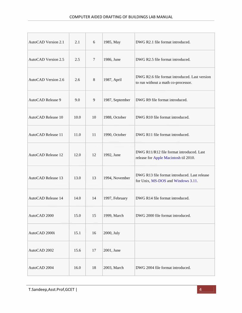
Official Name Version Release Date of release Comments
AutoCAD Version 1.0 1.0 1 1982, December DWG R1.0 file format introduced.
AutoCAD Version 1.2 1.2 2 1983, April DWG R1.2 file format introduced.
AutoCAD Version 1.3 1.3 3 1983, August DWG R1.3 file format introduced.
AutoCAD Version 1.4 1.4 4 1983, October DWG R1.4 file format introduced.
AutoCAD Version 2.0 2.0 5 1984, October DWG R2.05 file format introduced.
COMPUTER AIDED DRAFTING OF BUILDINGS LAB MANUAL
T.Sandeep,Asst.Prof,GCET | 4
AutoCAD Version 2.1 2.1 6 1985, May DWG R2.1 file format introduced.
AutoCAD Version 2.5 2.5 7 1986, June DWG R2.5 file format introduced.
AutoCAD Version 2.6 2.6 8 1987, April DWG R2.6 file format introduced. Last version
to run without a math co-processor.
AutoCAD Release 9 9.0 9 1987, September DWG R9 file format introduced.
AutoCAD Release 10 10.0 10 1988, October DWG R10 file format introduced.
AutoCAD Release 11 11.0 11 1990, October DWG R11 file format introduced.
AutoCAD Release 12 12.0 12 1992, June DWG R11/R12 file format introduced. Last
release for Apple Macintosh til 2010.
AutoCAD Release 13 13.0 13 1994, November DWG R13 file format introduced. Last release
for Unix, MS-DOS and Windows 3.11.
AutoCAD Release 14 14.0 14 1997, February DWG R14 file format introduced.
AutoCAD 2000 15.0 15 1999, March DWG 2000 file format introduced.
AutoCAD 2000i 15.1 16 2000, July
AutoCAD 2002 15.6 17 2001, June
AutoCAD 2004 16.0 18 2003, March DWG 2004 file format introduced.
COMPUTER AIDED DRAFTING OF BUILDINGS LAB MANUAL
T.Sandeep,Asst.Prof,GCET | 5
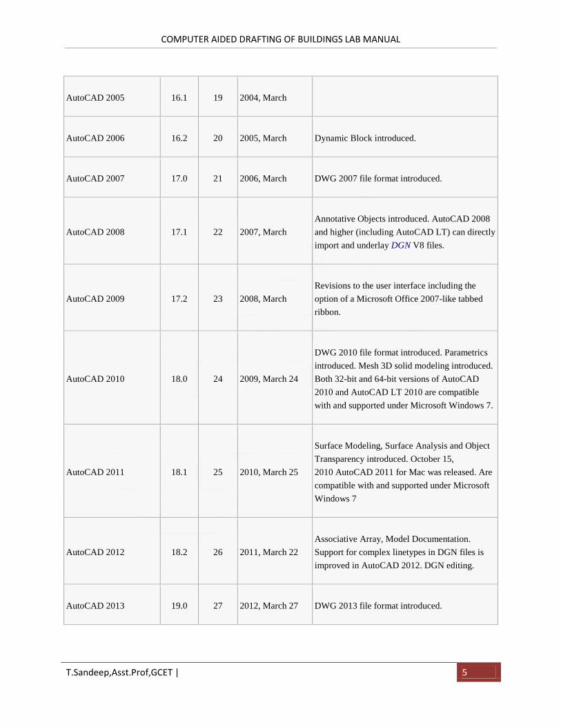
AutoCAD 2005 16.1 19 2004, March
AutoCAD 2006 16.2 20 2005, March Dynamic Block introduced.
AutoCAD 2007 17.0 21 2006, March DWG 2007 file format introduced.
AutoCAD 2008 17.1 22 2007, March
Annotative Objects introduced. AutoCAD 2008
and higher (including AutoCAD LT) can directly
import and underlay DGN V8 files.
AutoCAD 2009 17.2 23 2008, March
Revisions to the user interface including the
option of a Microsoft Office 2007-like tabbed
ribbon.
AutoCAD 2010 18.0 24 2009, March 24
DWG 2010 file format introduced. Parametrics
introduced. Mesh 3D solid modeling introduced.
Both 32-bit and 64-bit versions of AutoCAD
2010 and AutoCAD LT 2010 are compatible
with and supported under Microsoft Windows 7.
AutoCAD 2011 18.1 25 2010, March 25
Surface Modeling, Surface Analysis and Object
Transparency introduced. October 15,
2010 AutoCAD 2011 for Mac was released. Are
compatible with and supported under Microsoft
Windows 7
AutoCAD 2012 18.2 26 2011, March 22
Associative Array, Model Documentation.
Support for complex linetypes in DGN files is
improved in AutoCAD 2012. DGN editing.
AutoCAD 2013 19.0 27 2012, March 27 DWG 2013 file format introduced.
COMPUTER AIDED DRAFTING OF BUILDINGS LAB MANUAL
T.Sandeep,Asst.Prof,GCET | 6
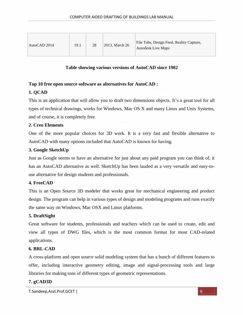
AutoCAD 2014 19.1 28 2013, March 26 File Tabs, Design Feed, Reality Capture,
Autodesk Live Maps
Table showing various versions of AutoCAD since 1982
Top 10 free open source software as alternatives for AutoCAD :
1. QCAD
This is an application that will allow you to draft two dimensions objects. It’s a great tool for all
types of technical drawings, works for Windows, Mac OS X and many Linux and Unix Systems,
and of course, it is completely free.
2. Creo Elements
One of the more popular choices for 3D work. It is a very fast and flexible alternative to
AutoCAD with many options included that AutoCAD is known for having.
3. Google SketchUp
Just as Google seems to have an alternative for just about any paid program you can think of, it
has an AutoCAD alternative as well. SketchUp has been lauded as a very versatile and easy-to-
use alternative for design students and professionals.
4. FreeCAD
This is an Open Source 3D modeler that works great for mechanical engineering and product
design. The program can help in various types of design and modeling programs and runs exactly
the same way on Windows, Mac OSX and Linux platforms.
5. DraftSight
Great software for students, professionals and teachers which can be used to create, edit and
view all types of DWG files, which is the most common format for most CAD-related
applications.
6. BRL-CAD
A cross-platform and open source solid modeling system that has a bunch of different features to
offer, including interactive geometry editing, image and signal-processing tools and large
libraries for making tons of different types of geometric representations.
7. gCAD3D
COMPUTER AIDED DRAFTING OF BUILDINGS LAB MANUAL
T.Sandeep,Asst.Prof,GCET | 7
This free software offers many features, including an integrated 3D-OpenGL viewer, a program
interpreter for geometry and NC commands in 3D, an integrated NC processor and can be used
with Windows and Linux. The website is a little sparse and confusing, but the freeware is not.
8. Archimedes
A 3D modeling application that allows you to create complex compound 3D shapes. It is touted
for being one of the most functional free AutoCAD alternatives out there.
9. PythonCAD
One for the Linux users, this is a CAD package that was written in the Python programming
language, hence the name. One of the best open-source CAD packages for Linux, and it’s also
quite simple to use if you have any kind of prior experience with two and three dimensional
modeling.
10. progeCAD
This one is free for private use but cannot be used commercially. It reads and writes pretty much
all AutoCAD files and has an interface that is very similar to AutoCAD’s, which makes it highly
recommended among people who have experience with AutoCAD beforehand.
DWG (DraWinG) is a binary file format used for storing two and three dimensional design data
and metadata. It is the native format for several CAD packages
including DraftSight, AutoCAD, IntelliCAD (and its variants)
We use commands in user interface of AutoCAD.
Commands are case Insensitive
Command means which had predefined function .
Viva Questions:
1. Who is the father of AutoCAD?
2. What is the difference between 2D and 3D?
3. What are paid licensed softwares other than AutoCAD?
COMPUTER AIDED DRAFTING OF BUILDINGS LAB MANUAL
T.Sandeep,Asst.Prof,GCET | 8
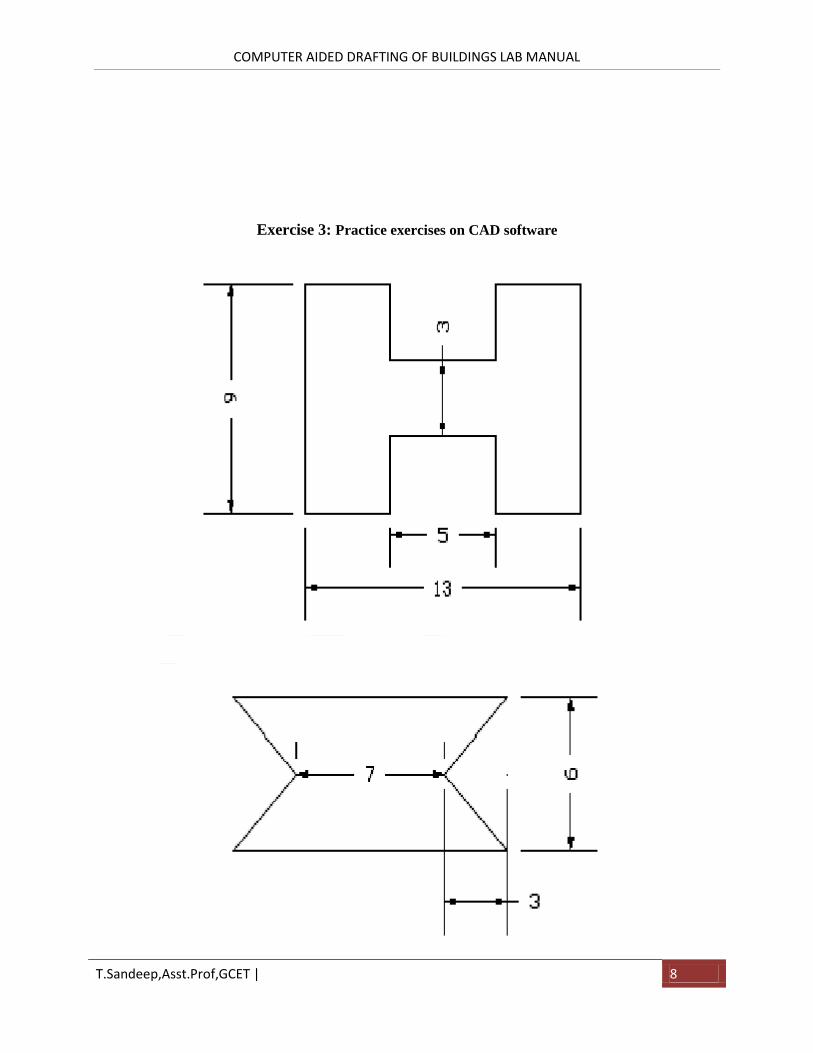
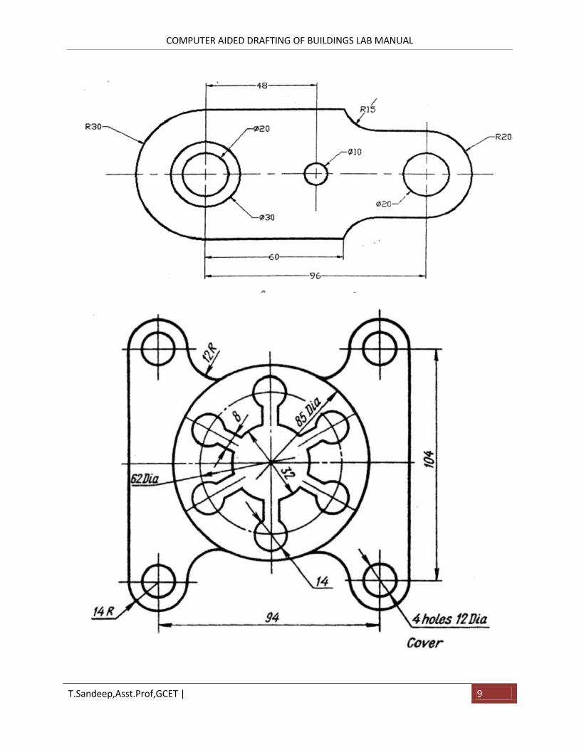
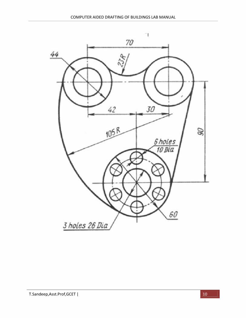
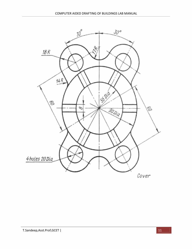
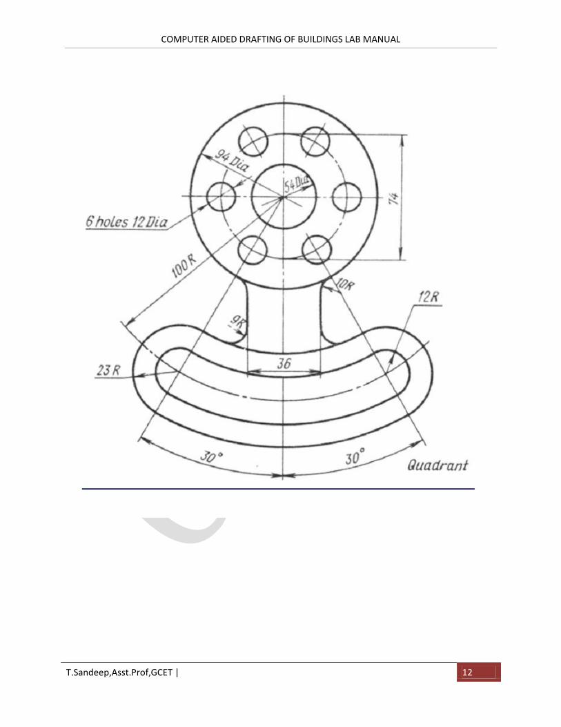
Exercise 3: Practice exercises on CAD software
COMPUTER AIDED DRAFTING OF BUILDINGS LAB MANUAL
T.Sandeep,Asst.Prof,GCET | 9
COMPUTER AIDED DRAFTING OF BUILDINGS LAB MANUAL
T.Sandeep,Asst.Prof,GCET | 10
COMPUTER AIDED DRAFTING OF BUILDINGS LAB MANUAL
T.Sandeep,Asst.Prof,GCET | 11
COMPUTER AIDED DRAFTING OF BUILDINGS LAB MANUAL
T.Sandeep,Asst.Prof,GCET | 12
COMPUTER AIDED DRAFTING OF BUILDINGS LAB MANUAL
T.Sandeep,Asst.Prof,GCET | 13
COMPUTER AIDED DRAFTING OF BUILDINGS LAB MANUAL
T.Sandeep,Asst.Prof,GCET | 14
COMPUTER AIDED DRAFTING OF BUILDINGS LAB MANUAL
T.Sandeep,Asst.Prof,GCET | 15
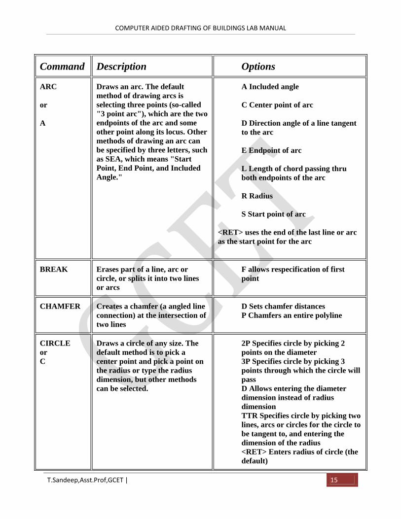
Command Description Options
ARC
or
A
Draws an arc. The default
method of drawing arcs is
selecting three points (so-called
"3 point arc"), which are the two
endpoints of the arc and some
other point along its locus. Other
methods of drawing an arc can
be specified by three letters, such
as SEA, which means "Start
Point, End Point, and Included
Angle."
A Included angle
C Center point of arc
D Direction angle of a line tangent
to the arc
E Endpoint of arc
L Length of chord passing thru
both endpoints of the arc
R Radius
S Start point of arc
<RET> uses the end of the last line or arc
as the start point for the arc
BREAK Erases part of a line, arc or
circle, or splits it into two lines
or arcs
F allows respecification of first
point
CHAMFER Creates a chamfer (a angled line
connection) at the intersection of
two lines
D Sets chamfer distances
P Chamfers an entire polyline
CIRCLE
or
C
Draws a circle of any size. The
default method is to pick a
center point and pick a point on
the radius or type the radius
dimension, but other methods
can be selected.
2P Specifies circle by picking 2
points on the diameter
3P Specifies circle by picking 3
points through which the circle will
pass
D Allows entering the diameter
dimension instead of radius
dimension
TTR Specifies circle by picking two
lines, arcs or circles for the circle to
be tangent to, and entering the
dimension of the radius
<RET> Enters radius of circle (the
default)
COMPUTER AIDED DRAFTING OF BUILDINGS LAB MANUAL
T.Sandeep,Asst.Prof,GCET | 16
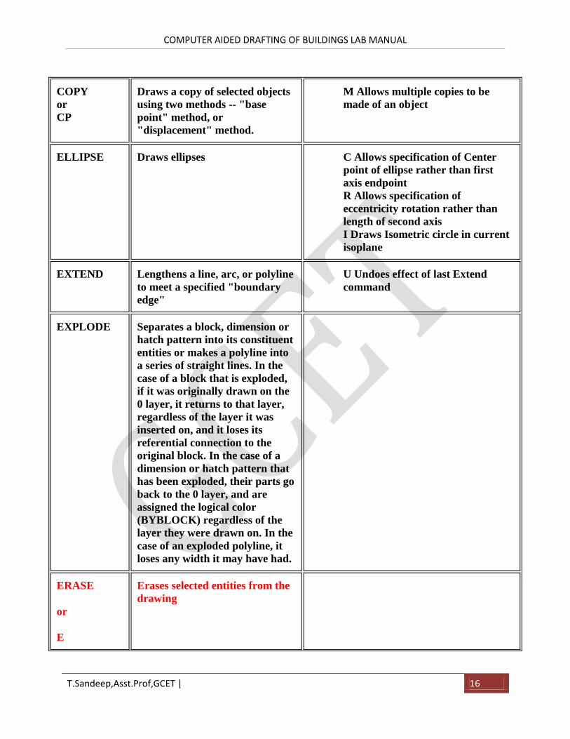
COPY
or
CP
Draws a copy of selected objects
using two methods -- "base
point" method, or
"displacement" method.
M Allows multiple copies to be
made of an object
ELLIPSE Draws ellipses C Allows specification of Center
point of ellipse rather than first
axis endpoint
R Allows specification of
eccentricity rotation rather than
length of second axis
I Draws Isometric circle in current
isoplane
EXTEND Lengthens a line, arc, or polyline
to meet a specified "boundary
edge"
U Undoes effect of last Extend
command
EXPLODE Separates a block, dimension or
hatch pattern into its constituent
entities or makes a polyline into
a series of straight lines. In the
case of a block that is exploded,
if it was originally drawn on the
0 layer, it returns to that layer,
regardless of the layer it was
inserted on, and it loses its
referential connection to the
original block. In the case of a
dimension or hatch pattern that
has been exploded, their parts go
back to the 0 layer, and are
assigned the logical color
(BYBLOCK) regardless of the
layer they were drawn on. In the
case of an exploded polyline, it
loses any width it may have had.
ERASE
or
E
Erases selected entities from the
drawing
COMPUTER AIDED DRAFTING OF BUILDINGS LAB MANUAL
T.Sandeep,Asst.Prof,GCET | 17
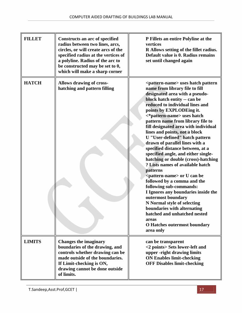
FILLET Constructs an arc of specified
radius between two lines, arcs,
circles, or will create arcs of the
specified radius at the vertices of
a polyline. Radius of the arc to
be constructed may be set to 0,
which will make a sharp corner
P Fillets an entire Polyline at the
vertices
R Allows setting of the fillet radius.
Default value is 0. Radius remains
set until changed again
HATCH Allows drawing of cross-
hatching and pattern filling
<pattern-name> uses hatch pattern
name from library file to fill
designated area with a pseudo-
block hatch entity -- can be
reduced to individual lines and
points by EXPLODEing it.
<*pattern-name> uses hatch
pattern name from library file to
fill designated area with individual
lines and points, not a block
U "User-defined" hatch pattern
drawn of parallel lines with a
specified distance between, at a
specified angle, and either single-
hatching or double (cross)-hatching
? Lists names of available hatch
patterns
<pattern-name> or U can be
followed by a comma and the
following sub-commands:
I Ignores any boundaries inside the
outermost boundary
N Normal style of selecting
boundaries with alternating
hatched and unhatched nested
areas
O Hatches outermost boundary
area only
LIMITS Changes the imaginary
boundaries of the drawing, and
controls whether drawing can be
made outside of the boundaries.
If Limit-checking is ON,
drawing cannot be done outside
of limits.
can be transparent
<2 points> Sets lower-left and
upper -right drawing limits
ON Enables limit-checking
OFF Disables limit-checking
COMPUTER AIDED DRAFTING OF BUILDINGS LAB MANUAL
T.Sandeep,Asst.Prof,GCET | 18
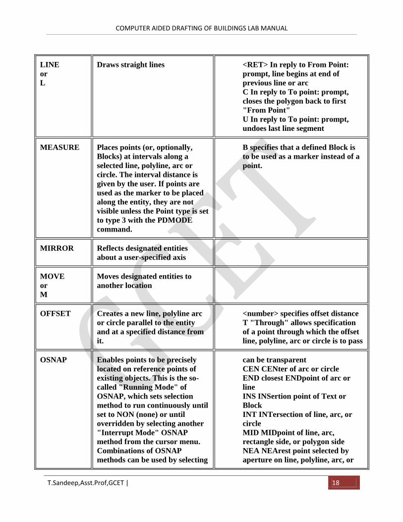
LINE
or
L
Draws straight lines <RET> In reply to From Point:
prompt, line begins at end of
previous line or arc
C In reply to To point: prompt,
closes the polygon back to first
"From Point"
U In reply to To point: prompt,
undoes last line segment
MEASURE Places points (or, optionally,
Blocks) at intervals along a
selected line, polyline, arc or
circle. The interval distance is
given by the user. If points are
used as the marker to be placed
along the entity, they are not
visible unless the Point type is set
to type 3 with the PDMODE
command.
B specifies that a defined Block is
to be used as a marker instead of a
point.
MIRROR Reflects designated entities
about a user-specified axis
MOVE
or
M
Moves designated entities to
another location
OFFSET Creates a new line, polyline arc
or circle parallel to the entity
and at a specified distance from
it.
<number> specifies offset distance
T "Through" allows specification
of a point through which the offset
line, polyline, arc or circle is to pass
OSNAP Enables points to be precisely
located on reference points of
existing objects. This is the so-
called "Running Mode" of
OSNAP, which sets selection
method to run continuously until
set to NON (none) or until
overridden by selecting another
"Interrupt Mode" OSNAP
method from the cursor menu.
Combinations of OSNAP
methods can be used by selecting
can be transparent
CEN CENter of arc or circle
END closest ENDpoint of arc or
line
INS INSertion point of Text or
Block
INT INTersection of line, arc, or
circle
MID MIDpoint of line, arc,
rectangle side, or polygon side
NEA NEArest point selected by
aperture on line, polyline, arc, or
COMPUTER AIDED DRAFTING OF BUILDINGS LAB MANUAL
T.Sandeep,Asst.Prof,GCET | 19
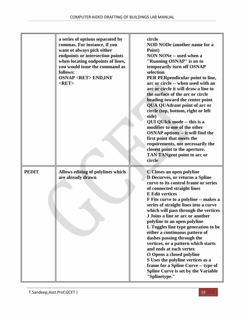
a series of options separated by
commas. For instance, if you
want ot always pick either
endpoints or intersection points
when locating endpoints of lines,
you would issue the command as
follows:
OSNAP <RET> END,INT
<RET>
circle
NOD NODe (another name for a
Point)
NON NONe -- used when a
"Running OSNAP" is on to
temporarily turn off OSNAP
selection
PER PERpendicular point to line,
arc or circle -- when used with an
arc or circle it will draw a line to
the surface of the arc or circle
heading toward the center point
QUA QUAdrant point of arc or
circle (top, bottom, right or left
side)
QUI QUIck mode -- this is a
modifier to one of the other
OSNAP options -- it will find the
first point that meets the
requirements, not necessarily the
closest point to the aperture.
TAN TANgent point to arc or
circle
PEDIT Allows editing of polylines which
are already drawn
C Closes an open polyline
D Decurves, or returns a Spline
curve to its control frame or series
of connected straight lines
E Edit vertices
F Fits curve to a polyline -- makes a
series of straight lines into a curve
which will pass through the vertices
J Joins a line or arc or another
polyline to an open polyline
L Toggles line type generation to be
either a continuous pattern of
dashes passing through the
vertices, or a pattern which starts
and ends at each vertex
O Opens a closed polyline
S Uses the polyline vertices as a
frame for a Spline Curve -- type of
Spline Curve is set by the Variable
"Splinetype."
COMPUTER AIDED DRAFTING OF BUILDINGS LAB MANUAL
T.Sandeep,Asst.Prof,GCET | 20
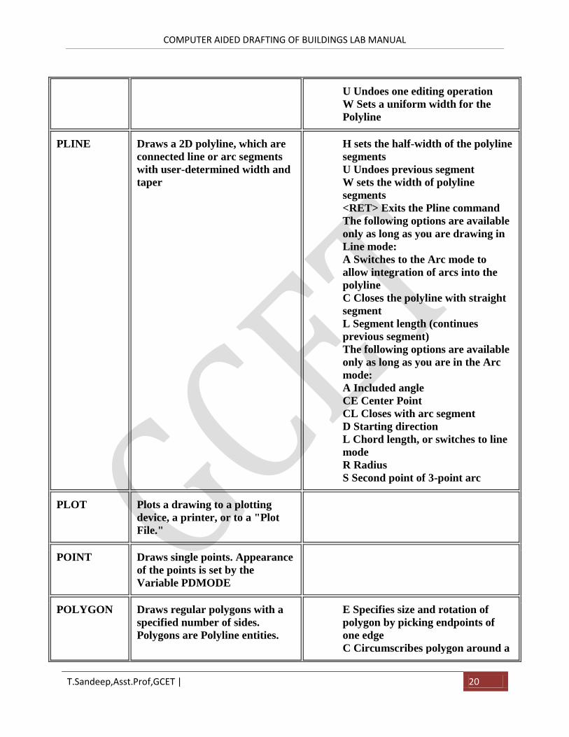
U Undoes one editing operation
W Sets a uniform width for the
Polyline
PLINE Draws a 2D polyline, which are
connected line or arc segments
with user-determined width and
taper
H sets the half-width of the polyline
segments
U Undoes previous segment
W sets the width of polyline
segments
<RET> Exits the Pline command
The following options are available
only as long as you are drawing in
Line mode:
A Switches to the Arc mode to
allow integration of arcs into the
polyline
C Closes the polyline with straight
segment
L Segment length (continues
previous segment)
The following options are available
only as long as you are in the Arc
mode:
A Included angle
CE Center Point
CL Closes with arc segment
D Starting direction
L Chord length, or switches to line
mode
R Radius
S Second point of 3-point arc
PLOT Plots a drawing to a plotting
device, a printer, or to a "Plot
File."
POINT Draws single points. Appearance
of the points is set by the
Variable PDMODE
POLYGON Draws regular polygons with a
specified number of sides.
Polygons are Polyline entities.
E Specifies size and rotation of
polygon by picking endpoints of
one edge
C Circumscribes polygon around a
COMPUTER AIDED DRAFTING OF BUILDINGS LAB MANUAL
T.Sandeep,Asst.Prof,GCET | 21
circle
I Inscribes polygon within a circle
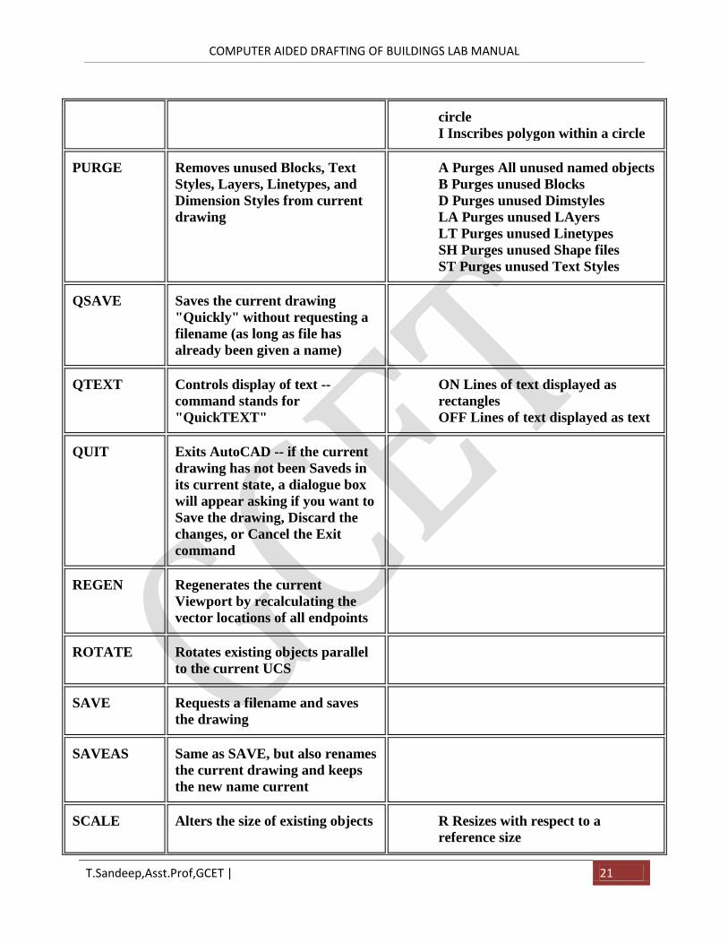
PURGE Removes unused Blocks, Text
Styles, Layers, Linetypes, and
Dimension Styles from current
drawing
A Purges All unused named objects
B Purges unused Blocks
D Purges unused Dimstyles
LA Purges unused LAyers
LT Purges unused Linetypes
SH Purges unused Shape files
ST Purges unused Text Styles
QSAVE Saves the current drawing
"Quickly" without requesting a
filename (as long as file has
already been given a name)
QTEXT Controls display of text --
command stands for
"QuickTEXT"
ON Lines of text displayed as
rectangles
OFF Lines of text displayed as text
QUIT Exits AutoCAD -- if the current
drawing has not been Saveds in
its current state, a dialogue box
will appear asking if you want to
Save the drawing, Discard the
changes, or Cancel the Exit
command
REGEN Regenerates the current
Viewport by recalculating the
vector locations of all endpoints
ROTATE Rotates existing objects parallel
to the current UCS
SAVE Requests a filename and saves
the drawing
SAVEAS Same as SAVE, but also renames
the current drawing and keeps
the new name current
SCALE Alters the size of existing objects R Resizes with respect to a
reference size
COMPUTER AIDED DRAFTING OF BUILDINGS LAB MANUAL
T.Sandeep,Asst.Prof,GCET | 22
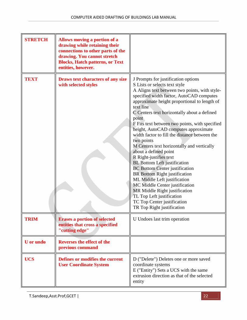
STRETCH Allows moving a portion of a
drawing while retaining their
connections to other parts of the
drawing. You cannot stretch
Blocks, Hatch patterns, or Text
entities, however.
TEXT Draws text characters of any size
with selected styles
J Prompts for justification options
S Lists or selects text style
A Aligns text between two points, with style-
specified width factor, AutoCAD computes
approximate height proportional to length of
text line
C Centers text horizontally about a defined
point
F Fits text between two points, with specified
height, AutoCAD computes approximate
width factor to fill the distance between the
two points
M Centers text horizontally and vertically
about a defined point
R Right-justifies text
BL Bottom Left justification
BC Bottom Center justification
BR Bottom Right justification
ML Middle Left justification
MC Middle Center justification
MR Middle Right justification
TL Top Left justification
TC Top Center justification
TR Top Right justification
TRIM Erases a portion of selected
entities that cross a specified
"cutting edge"
U Undoes last trim operation
U or undo Reverses the effect of the
previous command
UCS Defines or modifies the current
User Coordinate System
D ("Delete") Deletes one or more saved
coordinate systems
E ("Entity") Sets a UCS with the same
extrusion direction as that of the selected
entity
COMPUTER AIDED DRAFTING OF BUILDINGS LAB MANUAL
T.Sandeep,Asst.Prof,GCET | 23
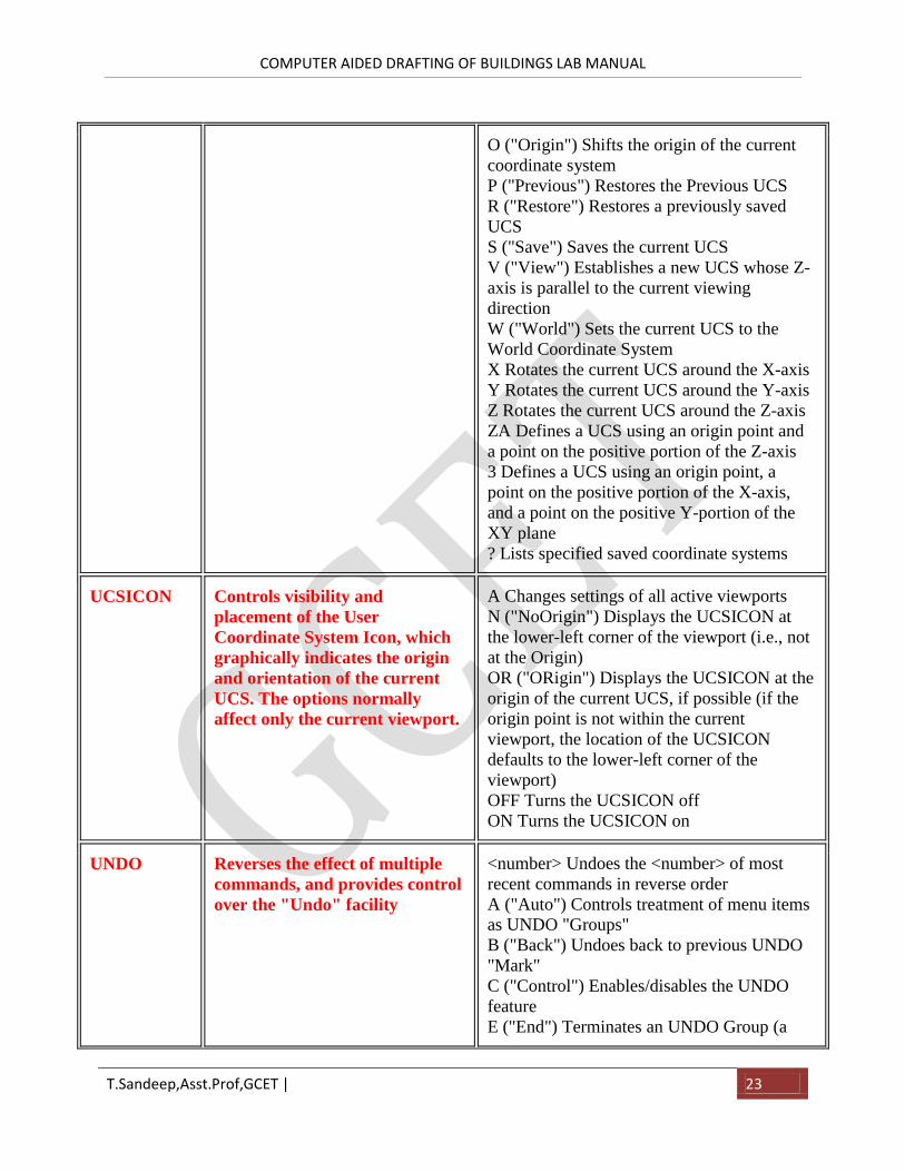
O ("Origin") Shifts the origin of the current
coordinate system
P ("Previous") Restores the Previous UCS
R ("Restore") Restores a previously saved
UCS
S ("Save") Saves the current UCS
V ("View") Establishes a new UCS whose Z-
axis is parallel to the current viewing
direction
W ("World") Sets the current UCS to the
World Coordinate System
X Rotates the current UCS around the X-axis
Y Rotates the current UCS around the Y-axis
Z Rotates the current UCS around the Z-axis
ZA Defines a UCS using an origin point and
a point on the positive portion of the Z-axis
3 Defines a UCS using an origin point, a
point on the positive portion of the X-axis,
and a point on the positive Y-portion of the
XY plane
? Lists specified saved coordinate systems
UCSICON Controls visibility and
placement of the User
Coordinate System Icon, which
graphically indicates the origin
and orientation of the current
UCS. The options normally
affect only the current viewport.
A Changes settings of all active viewports
N ("NoOrigin") Displays the UCSICON at
the lower-left corner of the viewport (i.e., not
at the Origin)
OR ("ORigin") Displays the UCSICON at the
origin of the current UCS, if possible (if the
origin point is not within the current
viewport, the location of the UCSICON
defaults to the lower-left corner of the
viewport)
OFF Turns the UCSICON off
ON Turns the UCSICON on
UNDO Reverses the effect of multiple
commands, and provides control
over the "Undo" facility
<number> Undoes the <number> of most
recent commands in reverse order
A ("Auto") Controls treatment of menu items
as UNDO "Groups"
B ("Back") Undoes back to previous UNDO
"Mark"
C ("Control") Enables/disables the UNDO
feature
E ("End") Terminates an UNDO Group (a
COMPUTER AIDED DRAFTING OF BUILDINGS LAB MANUAL
T.Sandeep,Asst.Prof,GCET | 24
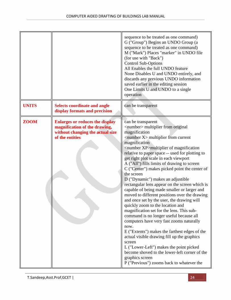
sequence to be treated as one command)
G ("Group") Begins an UNDO Group (a
sequence to be treated as one command)
M ("Mark") Places "marker" in UNDO file
(for use with "Back")
Control Sub-Options
All Enables the full UNDO feature
None Disables U and UNDO entirely, and
discards any previous UNDO information
saved earlier in the editing session
One Limits U and UNDO to a single
operation
UNITS Selects coordinate and angle
display formats and precision
can be transparent
ZOOM Enlarges or reduces the display
magnification of the drawing,
without changing the actual size
of the entities
can be transparent
<number> multiplier from original
magnification
<number X> multiplier from current
magnification
<number XP>multiplier of magnification
relative to paper space -- used for plotting to
get right plot scale in each viewport
A ("All") fills limits of drawing to screen
C ("Center") makes picked point the center of
the screen
D ("Dynamic") makes an adjustible
rectangular lens appear on the screen which is
capable of being made smaller or larger and
moved to different positions over the drawing
and once set by the user, the drawing will
quickly zoom to the location and
magnification set for the lens. This sub-
command is no longer useful because all
computers have very fast zooms naturally
now.
E ("Extents") makes the farthest edges of the
actual visible drawing fill up the graphics
screen
L ("Lower-Left") makes the point picked
become shoved to the lower-left corner of the
graphics screen
P ("Previous") zooms back to whatever the
COMPUTER AIDED DRAFTING OF BUILDINGS LAB MANUAL
T.Sandeep,Asst.Prof,GCET | 25
last zoom, previous to the current zoom was -
- AutoCAD stores about 10 of these, so you
can walk backward in zoom magnification 10
times
V ("Virtual Screen") makes the largest area
available to the graphics card fill the graphics
screen -- this varies with the quantity of
graphics RAM that your graphics card has
W ("Window") asks you to pick the lower left
corner and the upper right corner of a zoom
window and then fits that window to the
graphics screen
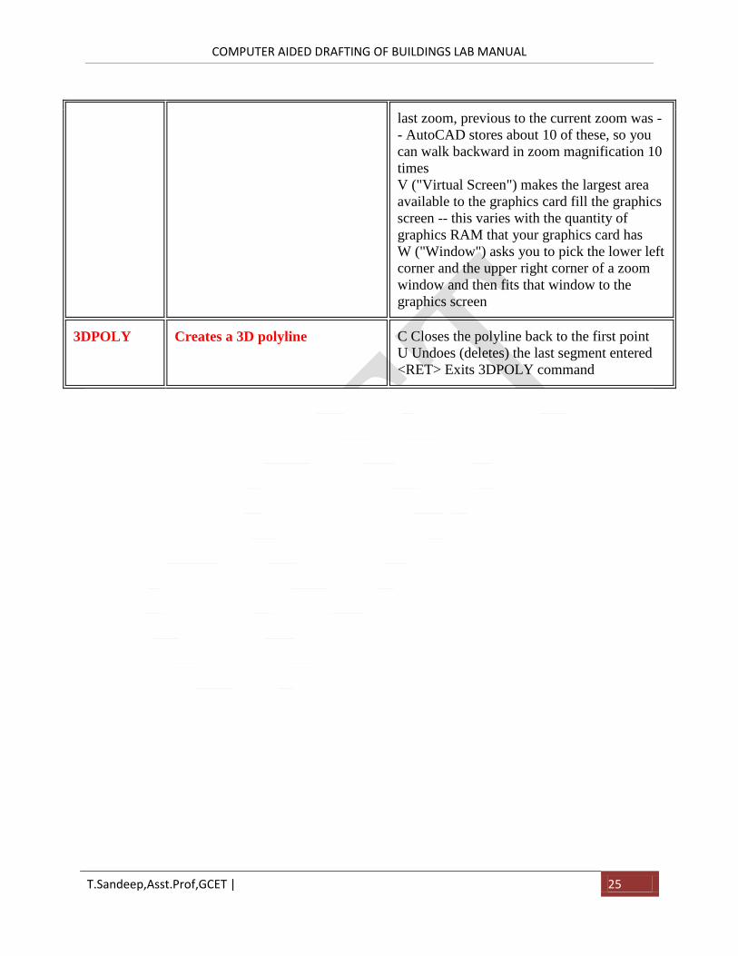
3DPOLY Creates a 3D polyline C Closes the polyline back to the first point
U Undoes (deletes) the last segment entered
<RET> Exits 3DPOLY command
COMPUTER AIDED DRAFTING OF BUILDINGS LAB MANUAL
T.Sandeep,Asst.Prof,GCET | 26
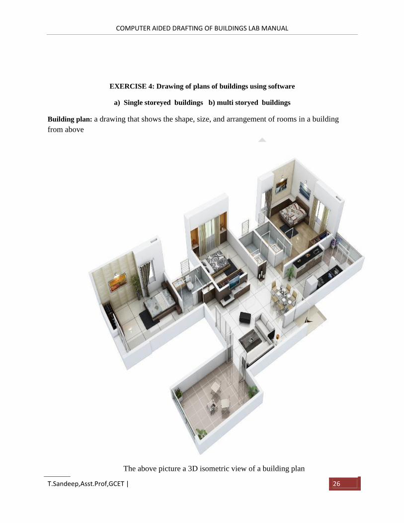
EXERCISE 4: Drawing of plans of buildings using software
a) Single storeyed buildings b) multi storyed buildings
Building plan: a drawing that shows the shape, size, and arrangement of rooms in a building
from above
The above picture a 3D isometric view of a building plan
COMPUTER AIDED DRAFTING OF BUILDINGS LAB MANUAL
T.Sandeep,Asst.Prof,GCET | 27
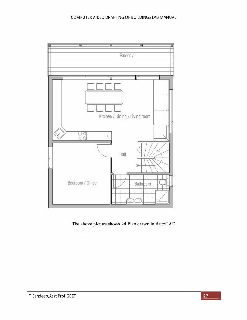
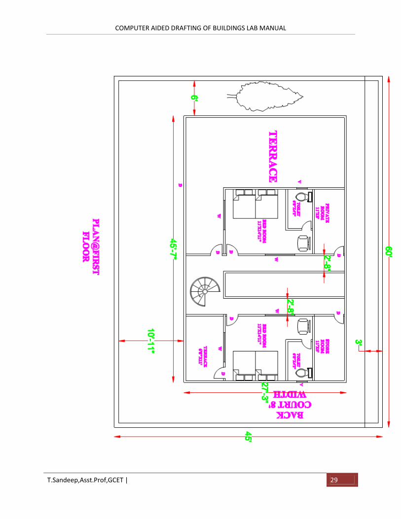
The above picture shows 2d Plan drawn in AutoCAD
COMPUTER AIDED DRAFTING OF BUILDINGS LAB MANUAL
T.Sandeep,Asst.Prof,GCET | 28
COMPUTER AIDED DRAFTING OF BUILDINGS LAB MANUAL
T.Sandeep,Asst.Prof,GCET | 29
COMPUTER AIDED DRAFTING OF BUILDINGS LAB MANUAL
T.Sandeep,Asst.Prof,GCET | 30
Exercise 6: Detailing of building components like Doors, Windows, Roof Trusses etc. using CAD
software
Types of Doors:
• Battened and ledge door
• Battened and braced door
• Battened and framed door
• Battened, ledge, and framed door
• Framed and paneled door
• Glazed door
• Flush door
• Louvered door
• Wire gauged door
• Revolving door
• Sliding door
• Swing door
• Collapsible steel door
• Rolling shutter door
• Mild steel sheet door
• Hollow metal door
• PVC door
Types of Windows :
• Fixed
• Pivoted
• Double hung
• Sliding
• Casement

COMPUTER AIDED DRAFTING OF BUILDINGS LAB MANUAL
T.Sandeep,Asst.Prof,GCET | 31
• Sash
• Louvered
• Metal
• Bay
• Corner window
• Dormer window
• Gable window
• Lantern