
Gebhardt, Michael On the hydraulic and structural design ...
12
Conference Paper, Published Version Gebhardt, Michael On the hydraulic and structural design of fluid and gas filled inflatable dams to control water flow in rivers Verfügbar unter/Available at: https://hdl.handle.net/20.500.11970/100800 Vorgeschlagene Zitierweise/Suggested citation: Gebhardt, Michael (2011): On the hydraulic and structural design of fluid and gas filled inflatable dams to control water flow in rivers. In: E. Oñate, B. Kröplin and K.-U.Bletzinger (Hg.): 5th Conference on Textile Composites and Inflatable Structures, Barcelona, Spain, 5-7 October 2011. Barcelona: CIMNE. S. 1-11. Standardnutzungsbedingungen/Terms of Use: Die Dokumente in HENRY stehen unter der Creative Commons Lizenz CC BY 4.0, sofern keine abweichenden Nutzungsbedingungen getroffen wurden. Damit ist sowohl die kommerzielle Nutzung als auch das Teilen, die Weiterbearbeitung und Speicherung erlaubt. Das Verwenden und das Bearbeiten stehen unter der Bedingung der Namensnennung. Im Einzelfall kann eine restriktivere Lizenz gelten; dann gelten abweichend von den obigen Nutzungsbedingungen die in der dort genannten Lizenz gewährten Nutzungsrechte. Documents in HENRY are made available under the Creative Commons License CC BY 4.0, if no other license is applicable. Under CC BY 4.0 commercial use and sharing, remixing, transforming, and building upon the material of the work is permitted. In some cases a different, more restrictive license may apply; if applicable the terms of the restrictive license will be binding.
Transcript of Gebhardt, Michael On the hydraulic and structural design ...
Conference Paper, Published Version
Gebhardt, MichaelOn the hydraulic and structural design of fluid and gasfilled inflatable dams to control water flow in rivers
Verfügbar unter/Available at: https://hdl.handle.net/20.500.11970/100800
Vorgeschlagene Zitierweise/Suggested citation:Gebhardt, Michael (2011): On the hydraulic and structural design of fluid and gas filledinflatable dams to control water flow in rivers. In: E. Oñate, B. Kröplin and K.-U.Bletzinger(Hg.): 5th Conference on Textile Composites and Inflatable Structures, Barcelona, Spain, 5-7October 2011. Barcelona: CIMNE. S. 1-11.
Standardnutzungsbedingungen/Terms of Use:
Die Dokumente in HENRY stehen unter der Creative Commons Lizenz CC BY 4.0, sofern keine abweichendenNutzungsbedingungen getroffen wurden. Damit ist sowohl die kommerzielle Nutzung als auch das Teilen, dieWeiterbearbeitung und Speicherung erlaubt. Das Verwenden und das Bearbeiten stehen unter der Bedingung derNamensnennung. Im Einzelfall kann eine restriktivere Lizenz gelten; dann gelten abweichend von den obigenNutzungsbedingungen die in der dort genannten Lizenz gewährten Nutzungsrechte.
Documents in HENRY are made available under the Creative Commons License CC BY 4.0, if no other license isapplicable. Under CC BY 4.0 commercial use and sharing, remixing, transforming, and building upon the materialof the work is permitted. In some cases a different, more restrictive license may apply; if applicable the terms ofthe restrictive license will be binding.
ON THE HYDRAULIC AND STRUCTURAL DESIGN OF FLUID AND
GAS FILLED INFLATABLE DAMS TO CONTROL WATER FLOW IN
RIVERS
M. GEBHARDT *, A. MAURER† AND K. SCHWEIZERHOF†
* Federal Waterways Engineering and Research Institute,
76187 Karlsruhe, Germany
e-mail: [email protected]
† Institute of Mechanics, Karlsruhe Institute of Technology,
76131 Karlsruhe, Germany
e-mail: [email protected], [email protected]
Key words: Inflatable dams, composites, design.
1 INTRODUCTION
The German Federal Waterways and Shipping Administration (WSV) operates about 280
weirs, half of which are more than 50 years old. Many of these weirs will therefore need to be
refurbished in the near future, even though budget resources are shrinking. An inflatable dam
is a relatively new gate type, which enables savings to be made on the capital spending and
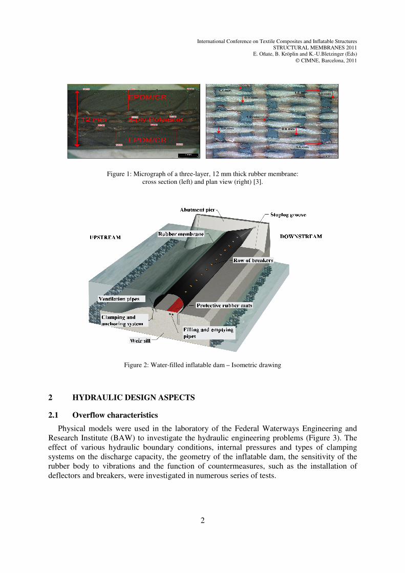
maintenance costs. It consists of a multi-ply rubber membrane (Figure 1), is filled with air or
water and clamped to the weir body with one or two fixing bars (Figure 2). Inflatable dams
have a number of advantages when compared with steel gates [2]:
- The design is simple and does not include any moving parts (hinges, bearings); there are
no problems due to corrosion or sealing and no lubricants used, which might be harmful
to the environment. Inflatable dams are not affected by settlements or earthquakes.
- Drive mechanisms, such as hydraulic cylinders, electrical actuators or chains, which
require a great amount of maintenance are not needed. Inflatable dams are controlled by
inflating or deflating by injecting and discharging air or water.
- The cost of recesses and reinforcement is low and the transfer of forces into the weir sill
is evenly distributed. Major refurbishments are thus facilitated considerably, especially
if the existing concrete structure has to be included.
- Inflatable dams can be operated safely and can always be deflated to prevent blocking.
The membranes can be installed or replaced within a few weeks so that the construction
times and periods for inspection and refurbishment are considerably reduced.
In spite of their advantages, there is still much scepticism regarding the use of inflatable
dams. This is partly due to the damage that has occurred in the past and partly due to the lack
of design principles.
International Conference on Textile Composites and Inflatable Structures
STRUCTURAL MEMBRANES 2011
E. Oñate, B. Kröplin and K.-U.Bletzinger (Eds)
CIMNE, Barcelona, 2011
2
Figure 1: Micrograph of a three-layer, 12 mm thick rubber membrane:
cross section (left) and plan view (right) [3].
Figure 2: Water-filled inflatable dam – Isometric drawing
2 HYDRAULIC DESIGN ASPECTS
2.1 Overflow characteristics
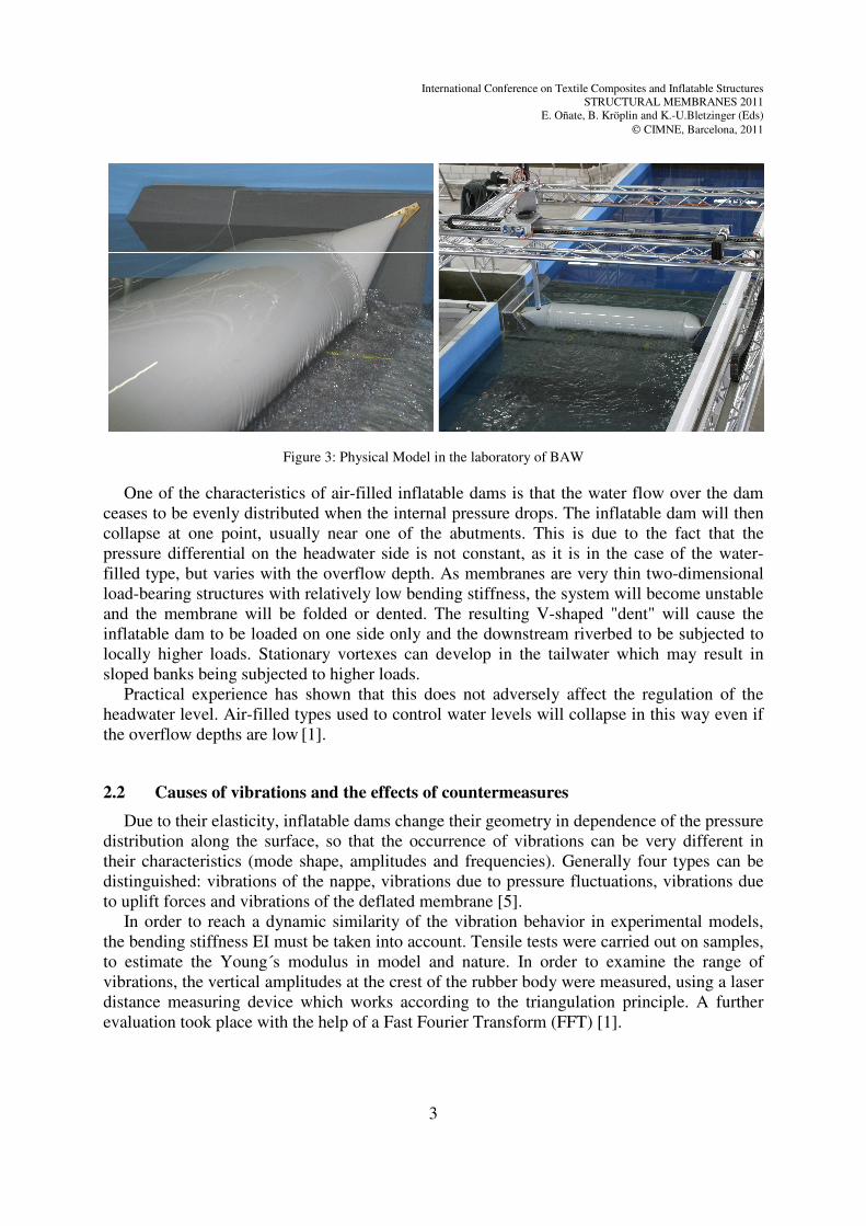
Physical models were used in the laboratory of the Federal Waterways Engineering and
Research Institute (BAW) to investigate the hydraulic engineering problems (Figure 3). The
effect of various hydraulic boundary conditions, internal pressures and types of clamping
systems on the discharge capacity, the geometry of the inflatable dam, the sensitivity of the
rubber body to vibrations and the function of countermeasures, such as the installation of
deflectors and breakers, were investigated in numerous series of tests.
International Conference on Textile Composites and Inflatable Structures
STRUCTURAL MEMBRANES 2011
E. Oñate, B. Kröplin and K.-U.Bletzinger (Eds)
CIMNE, Barcelona, 2011
3
Figure 3: Physical Model in the laboratory of BAW
One of the characteristics of air-filled inflatable dams is that the water flow over the dam
ceases to be evenly distributed when the internal pressure drops. The inflatable dam will then
collapse at one point, usually near one of the abutments. This is due to the fact that the
pressure differential on the headwater side is not constant, as it is in the case of the water-
filled type, but varies with the overflow depth. As membranes are very thin two-dimensional
load-bearing structures with relatively low bending stiffness, the system will become unstable
and the membrane will be folded or dented. The resulting V-shaped "dent" will cause the
inflatable dam to be loaded on one side only and the downstream riverbed to be subjected to
locally higher loads. Stationary vortexes can develop in the tailwater which may result in
sloped banks being subjected to higher loads.
Practical experience has shown that this does not adversely affect the regulation of the
headwater level. Air-filled types used to control water levels will collapse in this way even if
the overflow depths are low [1].
2.2 Causes of vibrations and the effects of countermeasures
Due to their elasticity, inflatable dams change their geometry in dependence of the pressure
distribution along the surface, so that the occurrence of vibrations can be very different in
their characteristics (mode shape, amplitudes and frequencies). Generally four types can be
distinguished: vibrations of the nappe, vibrations due to pressure fluctuations, vibrations due
to uplift forces and vibrations of the deflated membrane [5].
In order to reach a dynamic similarity of the vibration behavior in experimental models,
the bending stiffness EI must be taken into account. Tensile tests were carried out on samples,
to estimate the Young´s modulus in model and nature. In order to examine the range of
vibrations, the vertical amplitudes at the crest of the rubber body were measured, using a laser
distance measuring device which works according to the triangulation principle. A further
evaluation took place with the help of a Fast Fourier Transform (FFT) [1].
International Conference on Textile Composites and Inflatable Structures
STRUCTURAL MEMBRANES 2011
E. Oñate, B. Kröplin and K.-U.Bletzinger (Eds)
CIMNE, Barcelona, 2011
4
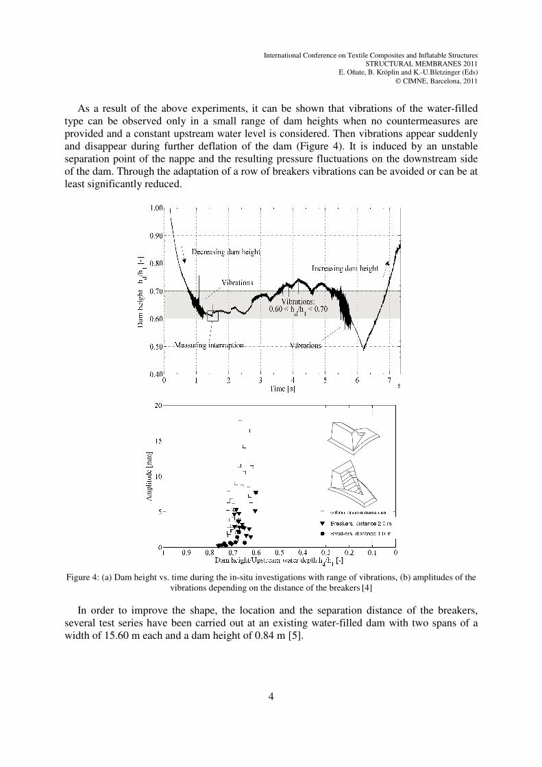
As a result of the above experiments, it can be shown that vibrations of the water-filled
type can be observed only in a small range of dam heights when no countermeasures are
provided and a constant upstream water level is considered. Then vibrations appear suddenly
and disappear during further deflation of the dam (Figure 4). It is induced by an unstable
separation point of the nappe and the resulting pressure fluctuations on the downstream side
of the dam. Through the adaptation of a row of breakers vibrations can be avoided or can be at
least significantly reduced.
Figure 4: (a) Dam height vs. time during the in-situ investigations with range of vibrations, (b) amplitudes of the
vibrations depending on the distance of the breakers [4]
In order to improve the shape, the location and the separation distance of the breakers,
several test series have been carried out at an existing water-filled dam with two spans of a
width of 15.60 m each and a dam height of 0.84 m [5].
International Conference on Textile Composites and Inflatable Structures
STRUCTURAL MEMBRANES 2011
E. Oñate, B. Kröplin and K.-U.Bletzinger (Eds)
CIMNE, Barcelona, 2011
5
3 STRUCTURAL DESIGN ASPECTS
3.1 Geometry and membrane force
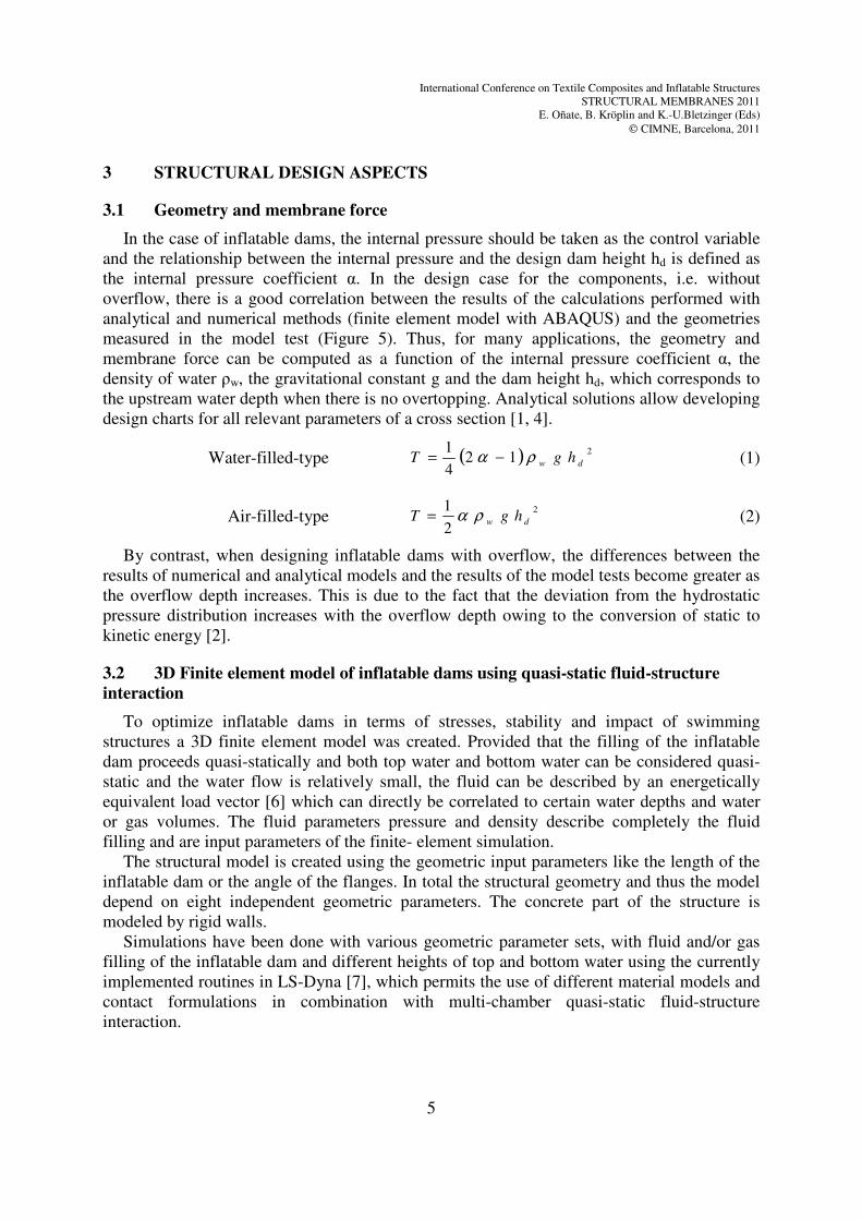
In the case of inflatable dams, the internal pressure should be taken as the control variable
and the relationship between the internal pressure and the design dam height hd is defined as
the internal pressure coefficient α. In the design case for the components, i.e. without
overflow, there is a good correlation between the results of the calculations performed with
analytical and numerical methods (finite element model with ABAQUS) and the geometries
measured in the model test (Figure 5). Thus, for many applications, the geometry and
membrane force can be computed as a function of the internal pressure coefficient α, the
density of water ρw, the gravitational constant g and the dam height hd, which corresponds to
the upstream water depth when there is no overtopping. Analytical solutions allow developing
design charts for all relevant parameters of a cross section [1, 4].
Water-filled-type ( ) 212
4
1dw hgT ρα −=
(1)
Air-filled-type 2
2
1dw hgT ρα= (2)
By contrast, when designing inflatable dams with overflow, the differences between the
results of numerical and analytical models and the results of the model tests become greater as
the overflow depth increases. This is due to the fact that the deviation from the hydrostatic
pressure distribution increases with the overflow depth owing to the conversion of static to
kinetic energy [2].
3.2 3D Finite element model of inflatable dams using quasi-static fluid-structure
interaction
To optimize inflatable dams in terms of stresses, stability and impact of swimming
structures a 3D finite element model was created. Provided that the filling of the inflatable
dam proceeds quasi-statically and both top water and bottom water can be considered quasi-
static and the water flow is relatively small, the fluid can be described by an energetically
equivalent load vector [6] which can directly be correlated to certain water depths and water
or gas volumes. The fluid parameters pressure and density describe completely the fluid
filling and are input parameters of the finite- element simulation.
The structural model is created using the geometric input parameters like the length of the
inflatable dam or the angle of the flanges. In total the structural geometry and thus the model
depend on eight independent geometric parameters. The concrete part of the structure is
modeled by rigid walls.
Simulations have been done with various geometric parameter sets, with fluid and/or gas
filling of the inflatable dam and different heights of top and bottom water using the currently
implemented routines in LS-Dyna [7], which permits the use of different material models and
contact formulations in combination with multi-chamber quasi-static fluid-structure
interaction.
International Conference on Textile Composites and Inflatable Structures
STRUCTURAL MEMBRANES 2011
E. Oñate, B. Kröplin and K.-U.Bletzinger (Eds)
CIMNE, Barcelona, 2011
6
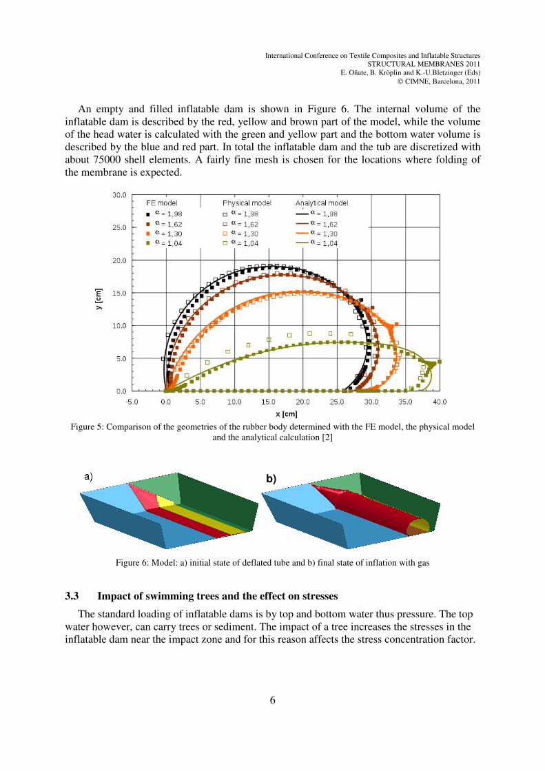
An empty and filled inflatable dam is shown in Figure 6. The internal volume of the
inflatable dam is described by the red, yellow and brown part of the model, while the volume
of the head water is calculated with the green and yellow part and the bottom water volume is
described by the blue and red part. In total the inflatable dam and the tub are discretized with
about 75000 shell elements. A fairly fine mesh is chosen for the locations where folding of
the membrane is expected.
Figure 5: Comparison of the geometries of the rubber body determined with the FE model, the physical model
and the analytical calculation [2]
Figure 6: Model: a) initial state of deflated tube and b) final state of inflation with gas
3.3 Impact of swimming trees and the effect on stresses
The standard loading of inflatable dams is by top and bottom water thus pressure. The top
water however, can carry trees or sediment. The impact of a tree increases the stresses in the
inflatable dam near the impact zone and for this reason affects the stress concentration factor.
b)
International Conference on Textile Composites and Inflatable Structures
STRUCTURAL MEMBRANES 2011
E. Oñate, B. Kröplin and K.-U.Bletzinger (Eds)
CIMNE, Barcelona, 2011
7
In the finite element simulations the tree is modeled by a cylinder of length 5m and weight
4t which swims with a constant velocity and hits the inflated dam under an angle between 0°
and 90°. To show the effects of the filling the dams have been filled with different water
heights and gas pressures.
Considerations show, that – not unexpected - a higher velocity of the tree or a completely
gas filled dam with a low gas pressure would cause the longest deformations and highest
stresses.
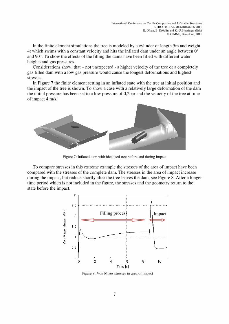
In Figure 7 the finite element setting in an inflated state with the tree at initial position and
the impact of the tree is shown. To show a case with a relatively large deformation of the dam
the initial pressure has been set to a low pressure of 0,2bar and the velocity of the tree at time
of impact 4 m/s.
Figure 7: Inflated dam with idealized tree before and during impact
To compare stresses in this extreme example the stresses of the area of impact have been
compared with the stresses of the complete dam. The stresses in the area of impact increase
during the impact, but reduce shortly after the tree leaves the dam, see Figure 8. After a longer
time period which is not included in the figure, the stresses and the geometry return to the
state before the impact.
Figure 8: Von Mises stresses in area of impact
Filling process Impact
International Conference on Textile Composites and Inflatable Structures
STRUCTURAL MEMBRANES 2011
E. Oñate, B. Kröplin and K.-U.Bletzinger (Eds)
CIMNE, Barcelona, 2011
8
Comparing these maximum stresses in the area of impact with the maximum stresses near
the flanges shows that these impact stresses do not change the stress concentration factor
which is important for design. The maximum von Mises stresses in this particular inflatable
dam are about 6 MPa, while the maximum stresses in the impact area do not exceed 2,9 MPa.
For lower velocities of the tree or dams filled with water the effect of the impact on the
stresses is even smaller. So in general we can conclude that the impacts of object such as trees
do not affect the maximum stresses of a dam. Further investigations will include the effect of
sharp edges and the overrun of trees with sharper parts.
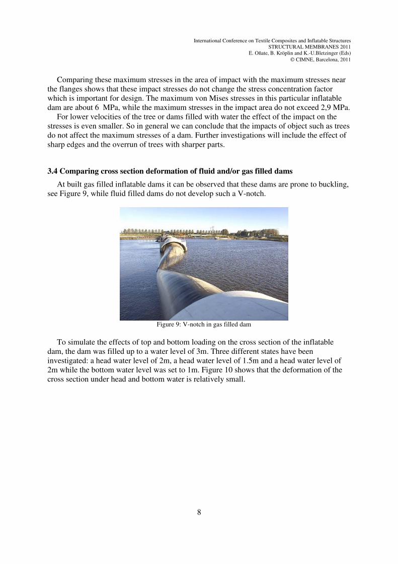
3.4 Comparing cross section deformation of fluid and/or gas filled dams
At built gas filled inflatable dams it can be observed that these dams are prone to buckling,
see Figure 9, while fluid filled dams do not develop such a V-notch.
Figure 9: V-notch in gas filled dam
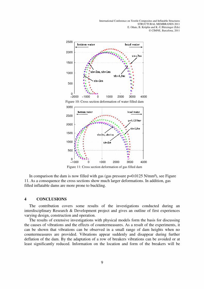
To simulate the effects of top and bottom loading on the cross section of the inflatable
dam, the dam was filled up to a water level of 3m. Three different states have been
investigated: a head water level of 2m, a head water level of 1.5m and a head water level of
2m while the bottom water level was set to 1m. Figure 10 shows that the deformation of the
cross section under head and bottom water is relatively small.
International Conference on Textile Composites and Inflatable Structures
STRUCTURAL MEMBRANES 2011
E. Oñate, B. Kröplin and K.-U.Bletzinger (Eds)
CIMNE, Barcelona, 2011
9
Figure 10: Cross section deformation of water filled dam
Figure 11: Cross section deformation of gas filled dam
In comparison the dam is now filled with gas (gas pressure p=0.0125 N/mm²), see Figure
11. As a consequence the cross sections show much larger deformations. In addition, gas
filled inflatable dams are more prone to buckling.
4 CONCLUSIONS
The contribution covers some results of the investigations conducted during an
interdisciplinary Research & Development project and gives an outline of first experiences
varying design, construction and operation.
The results of extensive investigations with physical models form the basis for discussing
the causes of vibrations and the effects of countermeasures. As a result of the experiments, it
can be shown that vibrations can be observed in a small range of dam heights when no
countermeasures are provided. Vibrations appear suddenly and disappear during further
deflation of the dam. By the adaptation of a row of breakers vibrations can be avoided or at
least significantly reduced. Information on the location and form of the breakers will be
International Conference on Textile Composites and Inflatable Structures
STRUCTURAL MEMBRANES 2011
E. Oñate, B. Kröplin and K.-U.Bletzinger (Eds)
CIMNE, Barcelona, 2011
10
discussed.
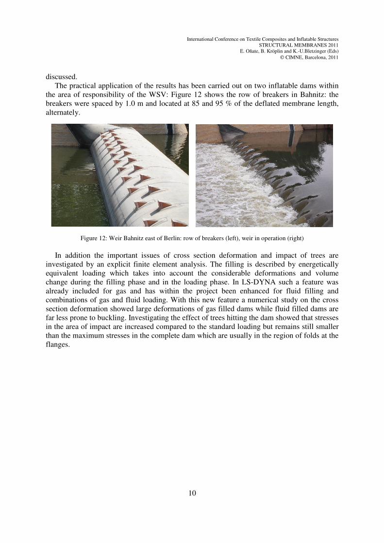
The practical application of the results has been carried out on two inflatable dams within
the area of responsibility of the WSV: Figure 12 shows the row of breakers in Bahnitz: the
breakers were spaced by 1.0 m and located at 85 and 95 % of the deflated membrane length,
alternately.
Figure 12: Weir Bahnitz east of Berlin: row of breakers (left), weir in operation (right)
In addition the important issues of cross section deformation and impact of trees are
investigated by an explicit finite element analysis. The filling is described by energetically
equivalent loading which takes into account the considerable deformations and volume
change during the filling phase and in the loading phase. In LS-DYNA such a feature was
already included for gas and has within the project been enhanced for fluid filling and
combinations of gas and fluid loading. With this new feature a numerical study on the cross
section deformation showed large deformations of gas filled dams while fluid filled dams are
far less prone to buckling. Investigating the effect of trees hitting the dam showed that stresses
in the area of impact are increased compared to the standard loading but remains still smaller
than the maximum stresses in the complete dam which are usually in the region of folds at the
flanges.
International Conference on Textile Composites and Inflatable Structures
STRUCTURAL MEMBRANES 2011
E. Oñate, B. Kröplin and K.-U.Bletzinger (Eds)
CIMNE, Barcelona, 2011
11
REFERENCES
[1] Gebhardt, M.: Hydraulische und Statische Bemessung von Schlauchwehren.
Mitteilungen des Instituts für Wasser und Gewässerentwicklung - Bereich
Wasserwirtschaft und Kulturtechnik der Universität Karlsruhe (TH),
Universitätsverlag Karlsruhe, (2006).
[2] Gebhardt, M.; Maisner, M.; Gabrys, U.: Inflatable dams - Prospects for the use of
flexible gates Advantages and application range - Hydraulic and structural design -
Requirements for materials - Initial experience on Federal waterways. 31st PIANC
CONGRESS, Estoril, Portugal, (May 2006).
[3] Gebhardt, M.; Maisner, M.; Nestmann, F., Schweizerhof, K.: Schlauchwehre als
Alternative zu Stahlwasserbauverschlüssen - Vorteile und Anwendungsgrenzen -
Hydraulische und statische Bemessung – Werkstoffanforderungen.
Wasserbausymposium Graz: Stauhaltungen und Speicher – Von der Tradition zur
Moderne, Graz, Austria, Schriftenreihe zur Wasserwirtschaft, Bd. 46/2, 401-415
(September 2006).
[4] Gebhardt, M., Nestmann, F., Schweizerhof, K., Kemnitz, B.: Grundlagen für die
hydraulische und statische Bemessung von wasser- und luftgefüllten Schlauchwehren,
Wasserwirtschaft, Vol. 3, 27-32, (2008).
[5] Gebhardt, M.: On the causes of vibrations and the effects of countermeasures at water-
filled inflatable dams. 1st European Division Congress of the International Association
of Hydraulic Engineering & Research (IAHR), Edinburg, UK, 1-6, (May 2010).
[6] Haßler, M., Schweizerhof, K.: On the static interaction of fluid and gas loaded multi-
chamber systems in a large deformation finite element analysis, Computer Methods in
Applied Mechanics and Engineering, 197, 1725-1748, (2008).
[7] Maurer, A., Gebhardt, M., Schweizerhof, K.: Computation of fluid and/or gas filled
inflatable dams, LS-Dyna Forum, Bamberg, Germany, (October 2010).