
Gas Turbine Flow Meter - aktek.com.tr
33
Gas Turbine Flow Meter User Manual www.aktek.com.tr
Transcript of Gas Turbine Flow Meter - aktek.com.tr

Gas Turbine Flow Meter User Manual
www.aktek.com.tr

1
Gas Turbine Flow Meter User Manual
CONTENT
I、 Overview ......................................................................................... 1
II、 Features ........................................................................................ 1
III、 Technical Data ............................................................................. 3
IV、 Working Principle, Structure and Size ........................................... 7
V、 Model Selection .............................................................................. 9
VI、 Installation ................................................................................... 13
VII、 Flow Meter Display/Parameters Setting ..................................... 15
VIII、 Terminal Structure & Connection Instruction of Flow meter ...... 17
IX、 Application Note .......................................................................... 21
X、 Notification for explosion-proof products ....................................... 22
XI、 Maintenance and troubleshooting ............................................... 24
XII、 Transportation and Storage ....................................................... 25
XIII、 Unpacking and Inspection ........................................................ 25
XIV、 Communication Protocol(RTU)(V1.0) ................................. 27
www.aktek.com.tr

1
Gas Turbine Flow Meter User Manual
I、Overview
The TRFM 1.0 -G Series gas turbine flow meter is a precision measuring instrument used
for gas flow measurement. This product is developed by AKTEK with the absorption of foreign
advanced technology combined with our own experience and expertise. It has small pressure
loss, high accuracy, and low dynamic flow, great anti-vibration and anti-pulsation performance,
wide range ratio, excellent low and high-pressure measurement performance, multiple signal
output methods and low sensitivity to fluid disturbances.
TRFM1.0-G Series gas turbine flow meter take into account the compressibility of gases,
and the correlation between volume, temperature and pressure of the medium. To convert
Process Condition medium to Standard Condition, temperature and pressure sensors are added
to track temperature and pressure changes of the measuring medium. TRFM1.0-G Series gas
turbine flowmeters are widely used in gas metering and gas pressure regulating stations for
petroleum gas, chemical gas, electric power and industrial boilers, as well as gas transmission
and distribution pipeline networks, urban natural gas metering. It is the preferred instrument for
trade settlements.
II、Features
● Advanced rectification technology assures the reliability of metering accuracy under
unsatisfactory installation conditions such as short front and rear straight pipe sections, vibrations,
or large variations of flow rate;
●The advanced dust-proof structure effectively prevent the rapid wear and stuck of bearing
caused by the impurities in the medium;
●Oxidized high-strength aluminum alloy turbine and impeller are corrosion-resistant, and
anti-ageing, they offer long service life, high accuracy, and good repeatability;
●German-made high-precision, dust-proof, stainless steel special bearings for flow meters, with
good stability, high accuracy, good sensitivity, long service life and wide range;
●Built-In temperature and pressure sensors can measure temperature, pressure and flow rate of
gases to be measured. The sensors are used to automatically compensate for temperature and
pressure change. Instantaneous flow and accumulated flow are displayed in normal condition
units.
●The intrinsically safe and flameproof circuit design is suitable for different explosion-proof
requirements;
www.aktek.com.tr

2
Gas Turbine Flow Meter User Manual
●Advanced dual-power supply, micro-power consumption technology. One set of two lithium
batteries are expected to operate 3+ years, it can also be connected to an external power
supply. TRFM1.0- G Series gas turbine flow meter also has battery under-voltage, or valve
closing alarm output Function, it is suitable for usage with an IC card management system;
●Diversified output signal, (4~20) mA standard analog signal, working condition pulse signal, IC
card standard volume signal and 485 communication available;
●According to user needs, the GPRS network function can be provided to realize low-cost,
long-distance wireless data real-time transmission; the Internet of Things interface function is
reserved to realize the LOT function.
●Internal battery low-voltage alarm reminds users to replace batteries in time;
●Intelligent flow Totalizer can rotate 350 degrees counterclockwise, convenient for data reading
in different directions;
●Time display and real-time data storage ensure that the internal data will not be lost and can be
stored permanently;
●Large-screen LCD, displaying rich and clear contents; The LCD screen of the Totalizer can
withstand a high temperature of 80℃;
●Flow upper limit and pressure upper alarm error display and record feature, allow users to
analyze flow patterns.
●Working modes can be switched automatically, battery-powered, two-wire system, and
three-wire system;
●When the system module fails, it will display the fault content and initiate the corresponding
mechanism;
●Diversified pressure ports, supports digital pressure sensor and pressure sensor; Pt100 or
Pt1000 temperature sensors are supported;
●Automatically run diagnosis upon pressure/temperature sensor failure. In the presence of
sensor failure, Totalizer will use preset pressure and temperature value for smart compensation.
●Unique reverse thrust structure design reduces and balances the bearing force, ensuring a
reliable long-term use of the bearing;
●The unique pressure balance design of the sealed chamber can effectively reduce wearing or
stuck of the bearing caused by dust or impurities.
www.aktek.com.tr

3
Gas Turbine Flow Meter User Manual
III、Technical Data
3.1 Operating Environment
1) Ambient Temperature: flameproof type: -20℃~+60℃, intrinsic safety type: -30℃~+50℃
2) Medium temperature: -30℃~+80℃
3) Relative Humidity: 5%~95%
4) Atmospheric pressure: 50kPa~110kPa
3.2 Nominal Diameter
DN25~DN400, larger diameter gas turbine flow meter can be manufactured upon request.
3.3 Pressure
(0.5~4.0) MPa, higher pressure versions gas turbine flow meter can be manufactured upon
request.
3.4 Measuring Range Ratio
Under standard environmental conditions (P=101.325kPa, T=293.15K), the range can reach
40:1 or wider.
(*Note: For some smaller diameter turbine flow meters, the ratio will be reduced).
3.5 accuracy
±1.0% (0.2Qmax~Qmax±1.0%; Qmin~0.2Qmax ±2.0%)
±1.5% (0.2Qmax~Qmax±1.5%; Qmin~0.2Qmax ±3.0%)
(*Note: Qmin is the minimum flow rate that can be measured within the flow rate range, and
Qmax is the maximum flow rate that can be measured within the flow rate range.
Special order meters are delivered according to 1.5 grades, and the other accuracy grades
need to be specified when ordering. )
3.6 Repeatability
Better than 0.2%
3.7 Explosion-proof Grade
ExiaⅡB T4 Ga, ExdⅡB T4 Gb, Protection grade: IP65
3.8 Shell Material
Aluminum alloy, Carbon steel, Stainless steel.
3.9 Electrical performance indicators
3.9.1 Power Supply
1) External power supply: +12~24VDC±15%, ripple <5%, suitable for 4~20mA output,
pulse output, alarm output, RS-485, etc.;
2) Internal power supply: 1 set of two 3.6V lithium batteries, when the voltage is lower
than 3.0V, an under-voltage indication will appear.
www.aktek.com.tr

4
gas Turbine Flow Meter User Manual
3.9.2 Power Consumption:
1) External power supply: <2W;
2) Internal power supply: average power consumption ≤1mW, a set of two lithium
batteries can be used continuously for more than 3 years, and power consumption ≤0.3mW
when in the sleep state.
3.9.3 Pulse Output Type:
1)Working condition pulse signal (FOUT), directly amplify and output the working
condition pulse signal detected by the flow sensor through optocoupler isolation, high-level ≥
20V, low-level ≤ 1V
2)Equivalent pulse signal (H/L), amplified and output by optocoupler isolation, high -level
amplitude ≥20V, low-level amplitude ≤1V, unit pulse represents the volume of standard
conditions. The settable range: 0.01 m3, 0.1 m3, 1m3, 10m3; upper and lower limit alarm
signal (H/L): photoelectric isolation, high and low-level alarm, working voltage +12V~+24V,
maximum load current 50mA
3.9.4 RS-485 communication(optoelectronic isolation), The following functions can
be achieved:
Using RS-485 interface, it can be directly connected to the host computer or secondary
meter, and can remotely transmit the medium’s temperature, pressure, instantaneous flow
rate, total standard volume and meter’s real-time data
3.9.5 4~20mA Standard current signal (photoelectric isolation)
It is proportional to the standard volume flow rate, 4mA corresponds to 0 m3/h, 20 mA
corresponds to the maximum standard volume flow rate (this value can be set in the first level
menu), system: two-wire or three-wire system, the flow meter can recognize and outputs
correctly based on the inserted current module automatically.
3.9.6 Control Signal Output:
1)IC card standard volume signal (IC_out): output in pulse signal, the pulse width is
50ms, 100ms, 500ms, the pulse amplitude is about 3V, normal level can be set, transmission
distance ≤50m, each pulse represents 0.01m3, 0.1m3, 1m3, 10m3, suitable for use with IC
card system
2)Battery voltage output (BC terminal, first-level battery low voltage alarm): open
collector output, amplitude ≥2.8V, load resistance ≥100kΩ;
3)Battery under-voltage alarm output (BL terminal, secondary battery low voltage alarm):
open collector output, amplitude ≥2.8V, load resistance ≥100kΩ
www.aktek.com.tr

5
Gas Turbine Flow Meter User Manual
3.9.7 Typical error curve of flow meter (see below figure)
www.aktek.com.tr

6
Gas Turbine Flow MeterUser Manual
3.9.8 The uncorrected flow range of the flow meter at the condition of air under normal
temperature and pressure
Diameter
(mm/inch
)
Model
Flow
specifi
cation
Flow Range
(m³/h)
Startup
Flow
Rate
(m³/h)
Maxi.
Pressur
e Loss
(kPa)
Shell
material
Weight
(kg)
DN25(1″) TRFM1.0-G-50(A) G50 5-50 ≤1 1
≤1.6MPa
aluminu
m
≥2.0MPa
carbon
steel or
SS304
7
DN40(1½ ″)TRFM1.0-G50(A) G60 6-60 ≤1 1 8
50(2″)
TRFM1.0-G-50(A) G40 6.5-65 ≤1.3 0.9
8.5 TRGM1.0-G-50(B) G65 8-100 ≤1.6 zz0.8
TRFM1.0-G-50(C) G100 10-160 ≤2.4 2.0
80(3″)
TRFM1.0-G-80(A) G100 8-160 ≤2.4 1.0
9.5 TRFM1.0-G-80(B) G160 13-250 ≤3.0 1.6
TRFM1.0-G-80(C) G250 20-400 ≤5.0 2.0
100(4″)
TRFM1.0-G-100(A) G160 13-250 ≤3.3 1.0
15 TRFM1.0-G-100(B) G250 20-400 ≤4.2 1.6
TRFM1.0-G-100(C) G400 32-650 ≤6.7 1.8
150(6″)
TRFM1.0-G-150(A) G400 32-650 ≤7.8 1.6
27 TRFM1.0-G-150(B) G650 50-1000 ≤10 2.0
TRFM1.0-G-150(C) G1000 80-1600 ≤12 2.3
200(8″)
TRFM1.0-G-200(A) G650 50-1000 ≤13 1.6
carbon
steel or
SS304
45 TRFM1.0-G-200(B) G1000 80-1600 ≤16 2.0
TRFM1.0-G-200(C) G1600 130-2500 ≤20 2.2
250(10″)
TRFM1.0-G-250(A) G1000 80-1600 ≤20 1.2
128 TRFM1.0-G-250(B) G1600 130-2500 ≤22 2.0
TRFM1.0-G-250(C) G2500 200-4000 ≤25 2.3
300(12″)
TRFM1.0-G-300(A) G1600 130-2500 ≤22 1.6
265 TRFM1.0-G-300(B) G2500 200-4000 ≤25 2.0
TRFM1.0-G-300(C) G4000 320-6500 ≤35 2.3
400(16″)
TRFM1.0-G-400(A) G1600 300-2500 ≤25 1.8
380 TRFM1.0-G-400(B) G2500 500-4000 ≤35 2.0
TRFM1.0-G-400(C) G4000 600-8000 ≤40 2.3
(1) Accuracy level: + -1.0%, + -1.5%;
(2) "Maximum pressure loss" is the measured pressure loss value when medium is air and max flow
under the standard state;
(3) The shell pressure grade:1.6MPa,2.5MPa,4.0MPa;
(4) Weight is reference data under pressure 1.6mpa;
(5) When other pressure specifications and special shell materials are needed, please specify when
ordering.
www.aktek.com.tr

7
Gas Turbine Flow Meter User Manual
IV、Working Principle, Structure and Size
4.1 Working Principle
When the gas flows into the flow meter, it is rectified and accelerated as it passes through the
integrated two-stage rectifier, then it acts on the turbine blades at a certain angle to the flow
direction. Under the momentum of the gas, because the turbine blades are at a certain angle with
the flow direction of the gas, the turbine generates a rotational torque at this time, the turbine
begins to rotate after it overcomes the resistance torque and the friction torque.
When the torques are balanced, the rotation speed is constant, and the turbine rotation
angular velocity has a linear relationship with the flow rate. Using the principle of electromagnetic
induction, a rotating turbine drives the top magnetizer of the signal generator to periodically
change the magnetic resistance, so that the magnetic field also changes accordingly, thereby
inducing a pulse signal proportional to the fluid volume flow.
The signal is amplified by the preamplifier, and after shaping, the pressure and temperature
signals detected by the pressure sensor and the temperature sensor are input to the flow totalizer
for calculation processing and converted into a flow value, which directly displays the standard
instantaneous volume flow and volume total flow.
4.2 Working Principle Diagram
4.3 Structure Drawing
www.aktek.com.tr

8
Gas Turbine Flow Meter User Manual
4.4 Gas turbine flow meter connection size
Nominal
Diameter L D K N-∅h H W Notes
DN25(1″) 200 115 85 4-φ14 335 200
1. Flange standard:
GB9113.1-2000
2. Pressure: 1.6MPa
3. Unit: mm
DN40(1½ ″) 200 15
0 110 4-φ18 365 230
DN50(2″) 150 16
5 125 4-φ18 375 275
DN80(3″) 240 20
0 160 8-φ18 409 280
DN100(4″) 300 22
0 180 8-φ18 430 285
DN150(6″) 450 28
5 240 8-φ22 495 370
DN200(8″) 600 34
0 295 12-φ22 559 390
DN250(10″) 750 40
5 355 12-φ26 629 480
DN300(12″) 900 46
0 410 12-φ26 680 535
DN400(16″) 1200 58
0 525 16-φ30 793 665
www.aktek.com.tr

9
Gas Turbine Flow Meter User Manual
V、Model Selection
Code Number
Nominal
Diameter
(mm)
Code
25 250
32 320
40 400
50 500
80 800
100 101
150 151
200 201
250 251
300 301
400 401
TRFM1.0-G Specifications ××× × × × × × × × ×
Nominal
Diameter (mm)
Check code
number
Flow Range
Check 4.9.8 A
Check 4.9.8 B
Check 4.9.8 C
Accuracy 1.0 Class 1
1.5 Class 2
Nominal
Pressure
1.0MPa 1
1.6MPa 2
2.5MPa 3
4.0MPa 4
Structure Remote Type 1
Compact Type 2
Body Material
Aluminum Alloy 1
Carbon Steel 2
Stainless Steel 3
Output/
Communication
Pulse 1
4~20mA 2
4~20mA+485 3
4~20mA+HART 4
Power Supply
External Power 24-30VDC(Two Wire Type) 1
External Power 24-30VDC(Three Wire Type) 2
Lithium Battery Powered (3.6VDC) 3
Ex-Proof
None 1
Intrinsically safe 2
Flameproof 3
www.aktek.com.tr
10
Gas Turbine Flow Meter User Manual
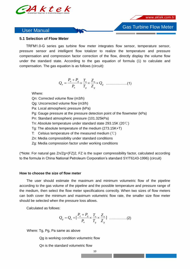
5.1 Selection of Flow Meter
TRFM1.0-G series gas turbine flow meter integrates flow sensor, temperature sensor,
pressure sensor and intelligent flow totalizer to realize the temperature and pressure
compensation and compression factor correction of the flow, directly display the volume flow
under the standard state. According to the gas equation of formula (1) to calculate and
compensation. The gas equation is as follows (circuit):
g
g
n
g
n
n
ga
n QZ
Z
T
T
P
PPQ
………………(1)
Where:
Qn: Corrected volume flow (m3/h)
Qg: Uncorrected volume flow (m3/h)
Pa: Local atmospheric pressure (kPa)
Pg: Gauge pressure at the pressure detection point of the flowmeter (kPa)
Pn: Standard atmospheric pressure (101.325kPa)
Tn: Absolute temperature under standard state 293.15K (20℃)
Tg: The absolute temperature of the medium (273.15K+T)
T: Celsius temperature of the measured medium (℃)
Zn: Media compressibility under standard conditions
Zg: Media compression factor under working conditions
(*Note: For natural gas Zn/Zg=(FZ)2, FZ is the super compressibility factor, calculated according
to the formula in China National Petroleum Corporation’s standard SY/T6143-1996) (circuit)
How to choose the size of flow meter
The user should estimate the maximum and minimum volumetric flow of the pipeline
according to the gas volume of the pipeline and the possible temperature and pressure range of
the medium, then select the flow meter specifications correctly. When two sizes of flow meters
can both cover the minimum and maximum volumetric flow rate, the smaller size flow meter
should be selected when the pressure loss allows.
Calculated as follows:
][g
n
g
n
n
ga
ngZ
Z
T
T
P
PPQQ
……………(2)
Where: Tg, Pg, Pa same as above
Qg is working condition volumetric flow
Qn is the standard volumetric flow
www.aktek.com.tr

11
Gas Turbine Flow Meter User Manual
Example of how to choose the size of flow meter
One pipeline actual working pressure range is gauge pressure (1.0~1.2) MPa, the medium
temperature is (-10~+40)℃, max standard flow is 10000m3/h, min standard flow is 3500 m3/h.
Natural gas actual relative density is Gr=0.519,N2 Moles is Mn=1.6%, CO2 Moles is MC=0.8%
When atmospheric pressure is 101.325kPa, which size of flow meter should choose?
According to the above information:
When the lowest pressure and highest temperature, according to formula SY/T6143-1996,
We can get that Zn/Zg=1.0127, and max volumetric flow:
][m a x
g
n
g
n
n
ga
ngZ
Z
T
T
P
PPQQ
=10000÷{[(1000+101.3)/101.325] ×[293.15/(273.15+40)] ×1.0127}
=970.5(m3/h)
The same we can get the min volumetric flow is 236 m3/h
Thus we need to choose DN150mm gas turbine flow meter.
Gas turbine flow meter pressure loss
The pressure loss of the gas turbine flow meter is related to the drive of the turbine flow meter,
the friction inside the pipeline, and the direction & speed of the fluid.
The pressure loss of the turbine flow meter in the working state is obtained by the following
formula:
2
max
max )(205.1 Q
Q
Z
Z
T
T
P
PPPP
g
n
g
n
n
gan
…………(3)
Meanings:
ρn:Density of gas in standard state
△ Pmax:Max. pressure lose in standard state(medium is dry air)
(20℃,101.325kPa, ρ=1.205kg/m3)
Pa:Local atmospheric pressure(kPa)
Pg:Medium meter pressure(kPa)
Pn:Standard atmospheric pressure(kPa)
Tn:Absolute temperature under standard condition(273.15+20℃)
Tg:Absolute temperature under working condition(273.15+T)
T:Tested medium temperature(℃)
Zn:Gas compressibility under standard conditions
Zg:Gas compressibility under working conditions
Q:flow under working condition(m3/h)
Qmax:Max flow under working condition(m3/h)
www.aktek.com.tr
12
Gas Turbine Flow Meter User Manual
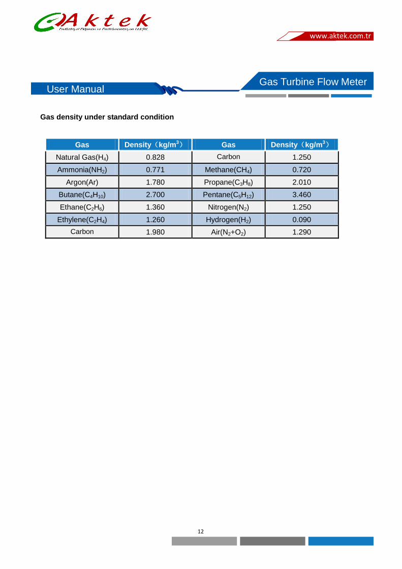
Gas density under standard condition
Gas Density(kg/m3) Gas Density(kg/m3)
Natural Gas(H4) 0.828 Carbon
monoxide(CO)
1.250
Ammonia(NH2) 0.771 Methane(CH4) 0.720
Argon(Ar) 1.780 Propane(C3H8) 2.010
Butane(C4H10) 2.700 Pentane(C5H12) 3.460
Ethane(C2H6) 1.360 Nitrogen(N2) 1.250
Ethylene(C2H4) 1.260 Hydrogen(H2) 0.090
Carbon
Dioxide(CO2)
1.980 Air(N2+O2) 1.290
www.aktek.com.tr

13
Gas Turbine Flow Meter User Manual
VI、Installation
To make sure high accuracy of the flow meter, we must install it correctly.
6.1 Straight Pipe Requirements:
1) Flow meter must install on the pipe horizontally(The inclination is within 5°),The axis of
the flow meter should be concentric with the axis of the pipeline during installation, and
the flow direction should be same
2) There should be straight pipe not less than 2D upstream of the flow meter. If it's possible,
it is recommended that the upstream straight pipe section be 20D and the downstream
be 5D.
6.2 Pipeline requirements:
Pipeline’s inner diameter should be same as flow meter’s inner diameter.(Both upstream and
downstream)
6.3 Bypass pipe requirements:
To make sure it would not affect the medium’s using while maintain the flow meter, we should
install shut off valve before and behind the pipe. Meanwhile, set the bypass pipe. Flow control
valve should install downstream of flow meter. While using the flow meter, upstream valves
should be all open to avoid unstable measurement.
6.4 Environment requirements:
Flow meter’s better install indoors. While install outdoors, please take sun protection, rain
protection measures so as not to affect the service life.
6.5 Impurities in the medium:
To ensure a long service life, should install a filter before flow meter.
6.6 Installation place:
Flow meter should be installed in a place that is convenient for maintenance and free from
strong electromagnetic interference and heat radiation.
www.aktek.com.tr

14
Gas Turbine Flow Meter User Manual
6.7 Installation and welding requirements:
1) User should match a pair of flanges to install flow meter, don’t welding the flow meter on
pipe directly.
2) Before installation, the welding slag and other dirt in the pipeline should be cleaned. It is
best to use an equal diameter pipeline (or bypass channel) instead of the flow meter to
purge the pipeline.
Notice: The gasket between the flanges cannot be recessed into the pipe.
6.8 Grounding:
Flow meter should be grounded reliably, it can not share ground wire with strong current
system.
6.9 Explosion Proof Requirements:
For safety, please check whether the working environment of the explosion-proof flow meter
conforms to the user's explosion-proof requirements and regulations. Please strictly abide by the
national explosion-proof product use requirements during installation and using. User is not
allowed to change the connection method of the explosion-proof system and is not allowed to
open the front and back cover, pressure port and other components of the flow meter.
6.10 Installation Diagram:
www.aktek.com.tr

15
Gas Turbine Flow Meter User Manual
VII、Flow Meter Display/Parameters Setting
7.1 Working Condition
Flow meter will perform a self-check when it is powered on. If the self-check is abnormal, the
self-check error menu will be displayed (refer to the self-check menu for the description), and it
will jump to the main interface after about 1 to 2 seconds. Otherwise, it will directly jump to the
main menu. After the main menu is started, it is as shown below:
Main interface
① : Total Flow
② : Working Condition
③ : Standard Condition
④ : Pressure
⑤ : Temperature
1) “OK”: The running status of the flow meter is displayed in real time. If it displays "OK" if it woks well, it
displays "ERR" if it’s fault
2) “OV”: The operating parameter of the instrument overflows. If the operating parameter of the instrument
overflows, it will display “OV”. If it is normal, it will display empty (overflow includes the parameter that
cannot be negative is negative, and the value that cannot be zero is zero, and the data exceeds the
display range);
3) “mA: The indicator of the current output overflow of the instrument, if the current overflows, it will display
"mA", if it is normal it will be empty;
4) “II” and “III”: Operating power supply mode display. If it is in battery mode, the current battery level will
be displayed. When the two-wire current output is connected, the number sign "II" will be displayed. If it
is three-wire system, the number sign "Ⅲ" will be displayed.
5) “IR”:Remote control button prompt, when this symbol appears, it indicates that the remote control
button is available.
6) Wireless communication, prompting the communication signal strength;
7) Total amount: cumulative flow, the display value can retain 5 decimal places, the maximum value is
999999999; the unit is m3, Nm3 for selection;
8) Flow rate under working conditions: the minimum display value is 3 decimal places, and the maximum
value is 99999m3/h;
9) Flow rate under standard conditions: the minimum displayed value is 3 decimal places, and the
maximum value is 99999Nm3/h;
10) Pressure: The minimum display value is 3 decimal places, the maximum value is 99999, and the unit
has Kpa and Mpa for selection;
11) Temperature: display value range is -50℃-300℃;
12) Operation power supply mode display, and displays battery power.
Warning: Don’t open the cover when there is explosive gas on site!
www.aktek.com.tr

16
Gas Turbine Flow Meter User Manual
7.2 Function description of keys
The flow meter is used to set the parameters by pressing the buttons. Generally, some parameters
need to be set manually by pressing the buttons during use. The flow meter has four buttons, from left to
right, there are four buttons: SET, SHT, INC and RST. The description of the buttons is as follows:
Button Name Function
SET
Set Key 1. Enter parameter setting; 2. Switch to display each parameter
item; 3. Confirm and save new parameters after modifying and
setting the parameter
SHT Shift Key Make the parameters flicker in turn
INC Plus Key To cause a bit of parameter to flicker from 0 to 9.
RST Exit Key Exit the parameter setting interface and enter the flow display
interface
www.aktek.com.tr

17
Gas Turbine Flow Meter User Manual
VIII、Terminal Structure & Connection Instruction of Flow
meter
8.1 Connection
1 2 3 4 5 6 7 8 9 10 11
VC
C
PI
N
GN
D MS
GN
D IP+
VP
+
VP
- IP- T1 T2
Flow Signal Magnetic Attach Interface Pressure Sensor Temperature Sensor
1) The flow meter can receive processed signals and can supply power to the signal processing
board. The wiring is as followings:
VCC: supply power 3V
PIN: frequency In
GND: ground
2) Magnetic Attack Interface:
MS: magnetic attack input
GND: ground
3) Pressure Sensor:
IP+,pressure sensor power supply +;
VP+,pressure sensor signal +;
VP-,pressure sensor signal -;
IP-,pressure sensor power supply -;
4) Temperature Sensor(Pt100 or Pt1000):
T1: Pt100(1)
T2: Pt100(2)
www.aktek.com.tr

18
Gas Turbine Flow Meter User Manual
8.2 External Terminal Definition
1) J17 Terminal Definition
2) J18 Terminal Definition
1 2 3 4 5 6 7 8
A1 B1 IC BC BL GND GND VCC
A1:Reserved RS485
B1:Reserved RS485
IC: IC card controller pulse (amplitude 3VDC)
BC: First level low power alarm, used for IC valve control
BL:Second order to low power alarm, used for IC valve control.
GND:IC card controller pulse Output -
GND: GND Output(Controllable)
VCC:+3VDC Output(Controllable)
1 2 3 4 5 6 7 8 9
+24v 0V I+ I- FOUT DOUT / A B
+24v:power supply DC24V+ FOUT: pulse output
0V:power supply 0V DOUT: equivalency output
I+: current output A: RS-485 A
I-: current output B: RS-485 B
www.aktek.com.tr

19
Gas Turbine Flow Meter User Manual
8.3 Output Wiring Instructions
1) Two-wire current connection:
2) Three-wire system current connection method:
3) Three-wire pulse connection:
www.aktek.com.tr

20
Gas Turbine Flow Meter User Manual
4) Three-wire equivalent connection:
5) RS485 Communication connection:
www.aktek.com.tr

21
Gas Turbine Flow Meter User Manual
IX、Application Note
1. The selection is within the specified flow range to prevent long-term overload operation to
ensure the desired accuracy and normal service life;
2. When the flow meter is installed and put into operation, the front valve should be opened
slowly, and then the rear valve should be opened to prevent instantaneous airflow from
damaging the turbine;
3. Lubricating oil should be operated in accordance with the refueling sign. The number of
refueling depends on the cleanliness of the temperament, usually every 2 to 3 months.
4. Prevent the turbine from over-speeding due to pressure test, purging pipes or exhaust, and
the turbine running in reverse flow may damage the flow meter;
5. It is not allowed to open the front cover at will when the flow meter is running (there is a circuit
board in the cover, and an accidental short circuit will cause electric sparks. When there is
flammable and explosive gas at the scene, it will cause serious accidents), and change the
operating parameters (changing the parameters will affect The normal operation of the flow
meter); (circuit)
6. Install gaskets carefully to ensure that no protrusions enter the pipeline to prevent
interference with normal flow measurement;
7. When the flow meter is calibrated, the pressure should be collected on the pressure port of
the flow meter. After the calibration is completed, the pressure port bolt should be tightened in
time to prevent air leakage during use;
8. The upper limit pressure should be correctly selected according to the actual working
pressure. The working pressure range of the corrector is required to be 20% Pmax ~ Pmax.
Too small a pressure will affect the measurement accuracy, and if the upper limit pressure is
too large, the pressure sensor will be damaged;
9. When the corrector is in operation, it is not allowed to open the back cover or change the
internal related parameters, otherwise it will affect its operation; (circuit)
10. If the correction instrument outputs a 4mA-20mA current signal, in order to improve its
accuracy, the user should set the value corresponding to 20mA according to the actual
maximum value. (Circuit)
www.aktek.com.tr

22
Gas Turbine Flow Meter User Manual
X、Notification for explosion-proof products
10.1 Intrinsically safe flow meter should follow the following items
1) The specific model specifications of the product certification are the products included
2) in this manual; (circuit)
3) The ambient temperature of the product is: -30 ℃ ~ + 50 ”; (circuit)
4) The battery must be replaced in a safe place; (circuit)
5) There is no harmful gas corrosive to aluminum alloy at the installation site; (circuit)
The product shell is equipped with a grounding terminal, and the user should be reliably
grounded when using it(Circuit)
6) The user shall not replace the parts of the product by himself, and shall work with the
company to solve the faults in operation to prevent damage(Circuit)
7) The safety barrier must be installed in a safe place, and its installation, use and
maintenance must comply with the safety barrier instruction manual
8) When installed and used on site, it must be connected with a safety barrier approved by
the explosion-proof inspection agency to form an intrinsically safe explosion-proof
system; if it is to be connected with other types of safety barriers, it must be approved by
the explosion-proof inspection agency
9) The connecting cable between the corrector and the safety barrier (the cable must have
an insulating sheath), the cross-sectional area of the core wire is ≥0.5mm2, the cable
wiring should eliminate the influence of electromagnetic interference as much as
possible, and the cable distribution parameters should be controlled within 0.04uF/1mH
10) When installing, using and maintaining this product, the user must also comply with the
instruction manual, GB3836.13-2013 "explosive gas environment, Part 13: Equipment
Repair, Overhaul, Repair and Transformation", GB/T3836.15-2017 "Electrical Equipment
for Explosive Gas Environment; Part 15: Electrical Installation in Hazardous Locations
(Except Coal Mines)", GB/T3836.16- 2017 "Electrical Equipment for Explosive Gas
Atmosphere; Part 16: Inspection and Maintenance of Electrical Equipment (Except Coal
Mines)" GB/T3836.18-2017 "Explosive Atmosphere; Part 18: Intrinsic Safety System"
and GB50257-2014 "Electrical Equipment Installation engineering explosion and fire
hazard environment electrical installations construction and acceptance regulations";
11) During normal working, maintenance and cleaning of the instrument, avoid the ignition
hazard caused by electrostatic charge. Do not touch or wipe the equipment when used in
an explosive environment. If you must wipe or touch, it should be carried out in a
well-ventilated place without gas leakage. Wipe the case with a damp cloth that has been
wrung out to avoid sparks caused by static friction. (Circuit)
www.aktek.com.tr

23
Gas Turbine Flow Meter User Manual
10.2 Explosion-proof flow meters should follow the following items:
1) Ambient temperature:-20℃~+60”
2) Please contact manufacturer for repairs involving flameproof joints
3) Measures should be taken to avoid the risk of ignition caused by electrostatic charges
on exposed non-metallic parts of the product
4) There is no harmful gas corrosive to aluminum alloy at the installation site
5) The shell grounding wire should be reliably grounded
6) Strictly abide by "It is strictly forbidden to open the cover when power is on" when using
and maintaining on site
7) The user shall not replace the parts of the product by himself
8) When installing, the cable entry must be equipped with a cable entry device that has
been approved by the explosion-proof inspection and has a thread specification of
M16X1.5, the corresponding explosion-proof grade, and the temperature resistance is
not less than 90°C and is compatible with the product.
9) When installing, using and maintaining the product, the user must strictly abide by the
product instruction manual and GB3836.13-2013 "Explosive Gas Atmosphere, Part 13:
Equipment Repair, Overhaul, Repair and Modification", GB/T3836.15-2017 "Electrical
equipment for explosive gas atmospheres; Part 15: Electrical installation in hazardous
locations", GB/T3836.16-2017 "Electrical equipment for explosive gas atmospheres;
Part 16: Inspection and maintenance of electrical installations" and GB50257-2014
"Electrical The relevant provisions of the “Code for Construction and Acceptance of
Electrical Installations in Explosive and Fire Hazardous Environments for Installation
Engineering”
www.aktek.com.tr

24
Gas Turbine Flow Meter User Manual
XI、Maintenance and troubleshooting
Fault
description Causes Solution
After power on
no output signal
1. No flow rate or flow rate is lower than starting flow
rate
2. Checking the power supply and whether
the output wiring is normal
1. Increase flow rate
2. Correct wiring
Display
instantaneous
flow under no
flow in pipe
1. Poor grounding of the flow meter or other
electrical interference
2. Unstable power supply, poor filtering or
other electrical interference
1. Correct grounding wiring, preclude
interference
2. Maintenance/replace power, preclude
interference
No display when
gas flows
through the flow
meter
1. Flow rate is lower than the starting flow
2. Impurities in the pipeline jam the impeller
3. Pressure difference between the two ends
of the instrument is too large to cause shock
4. The over-range causes the over-speed to
damage the bearing
1. Replace instrument or use smaller
size
2. Clean Impurities
3. Return to factory
Instantaneous
flow rate is
unstable
1. The impeller speed of the flow meter is
unstable and the flow is unstable
2. Poor grounding
3. Unstable power supply
4. There are impurities in the shell
5. The flow is below the low limit
6. The gasket extends into the pipe to cause
interference
7. Unsteady flow rate
1. Re install the impeller or remove dirt
2. Checking grounding wiring and make it
correct
3. Repair and replace the power supply,
eliminate interference
4. Remove dirt
5. Increase flow rate
6. Replace or correct sealing gasket
7. Measuring again after flow rate is
stable
Cumulative does
not match the
actual flow
1. Wrong K factor
2. The user's normal flow is lower or higher
than the normal flow range of the selected
flow meter
1. Enter new K factor
2. Adjust the pipeline flow rate to make
it normal or select appropriate
specifications
3. Calibrate again
Abnormal
Display Key issue Replace Key
Replace new
batteries
Crash
The power-on reset circuit is abnormal or the
oscillation circuit does not vibrate
Re install the battery (need to discharge
after 5 seconds)
www.aktek.com.tr

25
Gas Turbine Flow Meter User Manual
XII、Transportation and Storage
12.1 The flow meter should be packed in a wooden box (the medium and small diameters
should be packed in a carton with foam for anti-vibration). It is not allowed to move freely in the
box. When moving, handle it with care and do not allow rough handling.
12.2 The storage location should meet the following conditions
1) Rain proof and Moisture proof
2) Not subject to mechanical vibration or shock
3) Temperature range -30℃~+50℃
4) Relative humidity is not more than 80%
5) The environment does not contain corrosive gas
XIII、Unpacking and Inspection
13.1 Check the integrity of the external packaging when unpacking, check the contents,
specifications, and integrity of the instrument and accessories according to the packing
list.
13.2 Included documents:
1) Instruction manual (1 copy)
2) Product qualification certificate (1 copy)
3) Product inspection certificate (1 copy)
4)Packing list (1 copy)
13.3 Accessories
1) Filter gasket (1 piece)
2) Rubber gasket (1 piece)
3) Bearing lubricant (1 bottle)
Gas Turbine Flow Meter User Manual
www.aktek.com.tr

26
Gas Turbine Flow Meter User Manual
Order form
TRFM1.0-G Series Gas Turbine Flow Meter
Client's name: Order date:
Contact: Department:
Address: Postal code:
Tel: Fax:
E-mail: Delivery time:
Consignee: Tel:
Detailed delivery address:
Delivery method □Logistics □Express □Air □Other
Remarks:
Detailed parameters of flow meter
Model
Diameter
Material
Accuracy
Measuring medium
Max flow rate
Min flow rate
Min temperature
Max temperature
Min pressure
Max pressure
Ambient temperature
Environmental
pressure
Output
□(4~20)mA
□IC Card
Quantitative pulse
□Battery alarm signal
□Flow alarm signal
□(4~20)mA
□IC Card
Quantitative pulse
Battery alarm signal
□Flow alarm signal
□(4~20)mA
□IC Card
Quantitative pulse
□Battery alarm signal
□Flow alarm signal
Communication
□RS232C
□RS485
□MODBUS
□RS232C
□RS485
□MODBUS
□RS232C
□RS485
□MODBUS
Quantity Set Set Set
www.aktek.com.tr

27
Gas Turbine Flow Meter User Manual
XIV、 Communication Protocol(RTU)(V1.0)
14.1 Data Format Description
14.1.1 Communication Mode
This meter adopts MODBUS RTU Format.
The protocol is used for data communication in master-slave query mode.
14.1.2 Data Format
Data format is n, 8, 1(1 start bit, 8 data bits, 0 parity bit, 1 stop bit)
Baud: 1200, 2400, 4800, 9600
Start Address Function Data CRC Check END
T1-T2-T3-T4 8 bit 8 bit n*8 bit 16 bit T1-T2-T3-T4
Note: T1, T2, T3, T4 are the time intervals between each frame, and the transmission between
two frames must be greater than the interval time。
1.3 Address
The address of the instrument is specified in the protocol as “0-255”, the "0" address is used
for broadcasting( this protocol does not support broadcasting), and the rest are reserved.
14.2 Command Description
14.2.1 This instrument uses 1 command in MODBUS protocol as below:
Command 03 Read single or multiple holding registers
14.2.2 Data Format
The data in the protocol includes: integer, floating point
Integers are represented as 16-bit unsigned integers.
32 single-precision floating-point numbers (SINGLE format) is IEEE754, equivalent to 4 bytes,
the arrangement order is 3-4-1-2
After converting to the 1234 sequence, the positions from highest to lowest are 31st, 30th,
29th, ..., 0.
31 30-23 22-0
S Level Code Tail Code
The 31st bit is the sign bit (S), 1 indicates that the number is negative, 0 otherwise;
30-23 bit,Total 8 bit level code;
22-0 bit,Total 23 bit tail code.
Gas Turbine Flow Meter User Manual
www.aktek.com.tr
www.aktek.com.tr
28
Gas Turbine Flow Meter User Manual
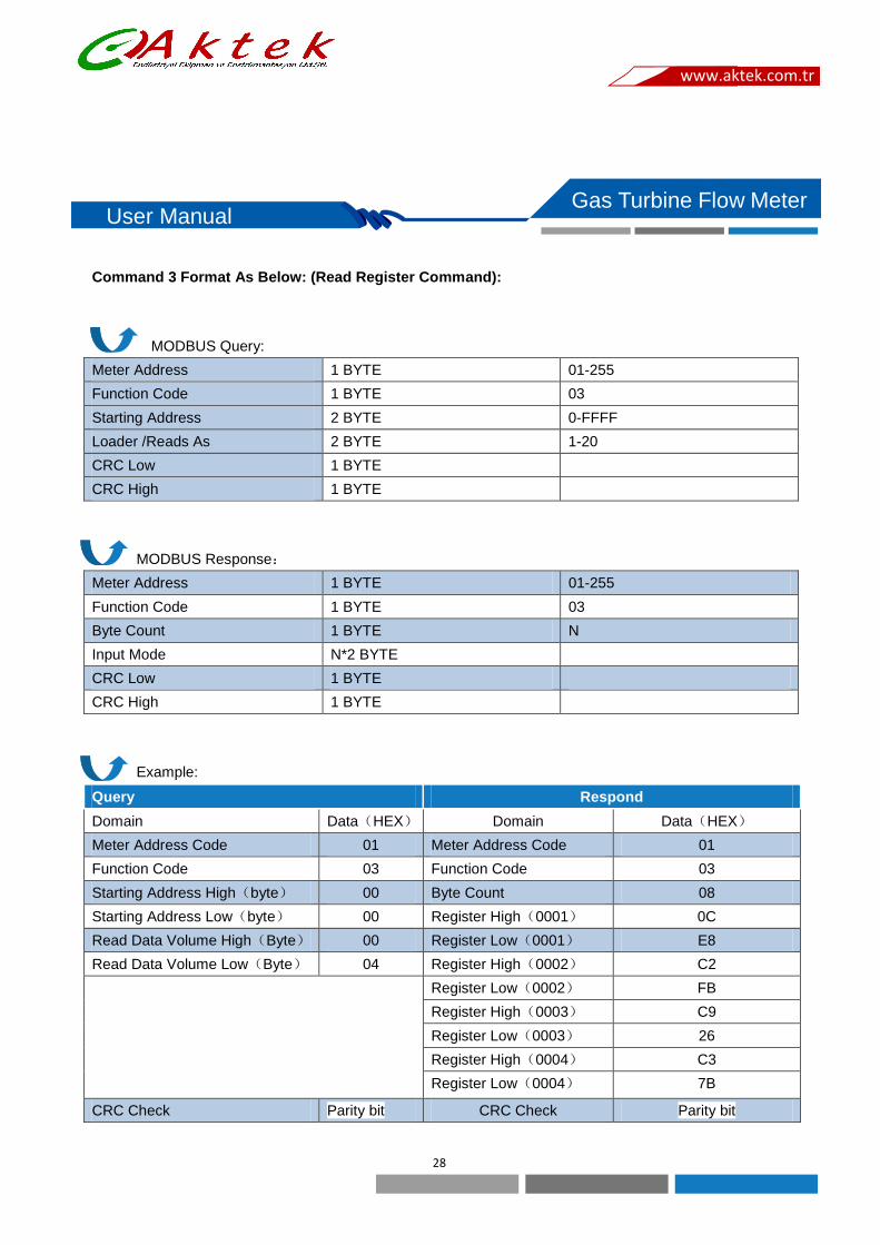
Command 3 Format As Below: (Read Register Command):
MODBUS Query:
Meter Address 1 BYTE 01-255
Function Code 1 BYTE 03
Starting Address 2 BYTE 0-FFFF
Loader /Reads As 2 BYTE 1-20
CRC Low 1 BYTE
CRC High 1 BYTE
MODBUS Response:
Meter Address 1 BYTE 01-255
Function Code 1 BYTE 03
Byte Count 1 BYTE N
Input Mode N*2 BYTE
CRC Low 1 BYTE
CRC High 1 BYTE
Example:
Query Respond
Domain Data(HEX) Domain Data(HEX)
Meter Address Code 01 Meter Address Code 01
Function Code 03 Function Code 03
Starting Address High(byte) 00 Byte Count 08
Starting Address Low(byte) 00 Register High(0001) 0C
Read Data Volume High(Byte) 00 Register Low(0001) E8
Read Data Volume Low(Byte) 04 Register High(0002) C2
Register Low(0002) FB
Register High(0003) C9
Register Low(0003) 26
Register High(0004) C3
Register Low(0004) 7B
CRC Check Parity bit CRC Check Parity bit
Gas Turbine Flow Meter User Manual
www.aktek.com.tr
29
Gas Turbine Flow Meter User Manual
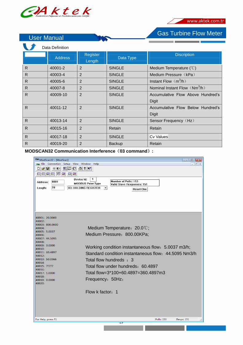
Data Definition
Read-Write Address
Register
Length Data Type
Discription
R 40001-2 2 SINGLE Medium Temperature (℃)
R 40003-4 2 SINGLE Medium Pressure(kPa)
R 40005-6 2 SINGLE Instant Flow(m3/h)
R 40007-8 2 SINGLE Nominal Instant Flow(Nm3/h)
R 40009-10 2 SINGLE Accumulative Flow Above Hundred’s
Digit
R 40011-12 2 SINGLE Accumulative Flow Below Hundred’s
Digit
R 40013-14 2 SINGLE Sensor Frequency(Hz)
R 40015-16 2 Retain Retain
R 40017-18 2 SINGLE Cv Values
R 40019-20 2 Backup Retain
MODSCAN32 Communication Interference(03 command):
Medium Temperature:20.0℃;
Medium Pressure:800.00KPa;
Working condition instantaneous flow:5.0037 m3/h;
Standard condition instantaneous flow:44.5095 Nm3/h
Total flow hundreds :3
Total flow under hundreds:60.4897
Total flow=3*100+60.4897=360.4897m3
Frequency:50Hz;
Flow k factor:1
www.aktek.com.tr

30
Gas Turbine Flow Meter User Manual
Temperature:20℃;
Pressure:800KPa;
Working condition instantaneous flow:5.0037 m3/h;
Standard condition instantaneous flow per second:44.5095 Nm3/h;
Total flow above hundred:3 Nm3
Total flow under hundred:60.4897 Nm3
Flow sensor frequency:50Hz
Flow K factor:1.000
Read register data (in this example, read the data displayed in the current converter)
Master request: 01 03 00 00 00 14 45 C5
Add Function Code Start Length CRC
Slave response frame:
01 03 28 00 00 41 A0 00 00 44 48 16 84 40 A0 01 6A 42 32 00 00 40 40 74 5E 42 86 1C 24 42 48
00 00 FF 00 00 00 3F 80 00 00 00 00 9A 67
01 03 28 Address, function code, number of bytes
00 00 41 A0 20℃;Temperature
00 00 44 48 80 Kpa;pressure
16 84 40 A0 5.002 m3/h;Working condition flow
01 6A 42 32 44.5013 Nm3/h;Standard condition flow
00 00 40 40 3.0 Nm3,Total flow hundreds
74 5E 42 86 67.2272 Nm3,total flow under hundreds;
total flow =3.0*100+67.2272= 367.2272
Nm3
1C 24 42 48 50.027Hz,frequency
00 00 FF 00 Reserve
00 00 3F 80 1.0 flow k factor
00 00 00 00 Reserve
4D 43 CRC Check
www.aktek.com.tr

Gas Turbine Flow Meter User Manual
Flow coefficient communication modification method (modified by Modscan32 software):
Flow coefficient communication modification method (Command No. 10 (send in HEX format)):
If the meter address is 1, write the coefficient 1.0, and send the data as follows:
Send:01 10 00 55 00 02 04 00 00 3F 80 26 FC
01 10 Add, Command No
00 55 Write start add
00 02 Write length
04 Send data byte length
00 00 3F 80 K factor(Float)
26 FC CRC Check
Return:01 10 00 55 00 02 51 D8 Returning this data indicates successful writing.
www.aktek.com.tr
Aktek Endüstriyel Ekipman ve Enstrümantasyon Ltd. Şti. İMES Sanayi Sitesi B Blok 204. Sk. No:40 Y. Dudullu Ümraniye İSTANBUL
Tel. 0216 540 7300 pbx, Fax. 0216 540 7303 www.aktek.com.tr [email protected]