TURBINE FLOW METERS INSTRUMENTATION · METER SPECIFICATIONS HIGH PRESSURE TURBINE FLOW METER - HM...
13
COMPANY TURBINE FLOW METERS INSTRUMENTATION
Transcript of TURBINE FLOW METERS INSTRUMENTATION · METER SPECIFICATIONS HIGH PRESSURE TURBINE FLOW METER - HM...

COMPANY
TURBINE FLOW METERS INSTRUMENTATION
2440 W. Corporate Preserve Dr. #600, Oak Creek, WI 53154 | www.aw-lake.comaw-infor
COMPANY
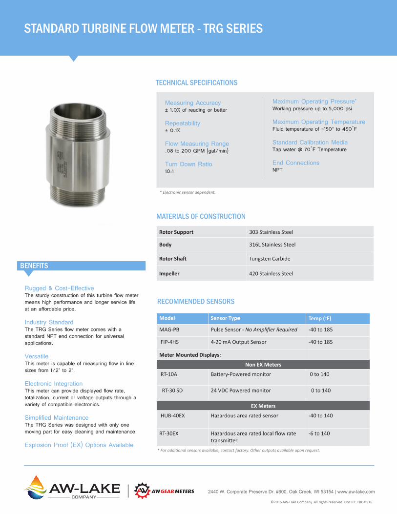
Rugged & Cost-EffectiveThe sturdy construction of this turbine flow meter means high performance and longer service life at an affordable price.
Industry StandardThe TRG Series flow meter comes with a standard NPT end connection for universal applications.
VersatileThis meter is capable of measuring flow in line sizes from 1/2” to 2”.
Electronic IntegrationThis meter can provide displayed flow rate, totalization, current or voltage outputs through a variety of compatible electronics.
Simplified MaintenanceThe TRG Series was designed with only one moving part for easy cleaning and maintenance.
Explosion Proof (EX) Options Available
BENEFITS
MATERIALS OF CONSTRUCTION
Rotor Support 303 Stainless Steel
Body 316L Stainless Steel
Rotor Shaft Tungsten Carbide
Impeller 420 Stainless Steel
Maximum Operating Pressure*
Working pressure up to 5,000 psi
Maximum Operating TemperatureFluid temperature of -150° to 450˚F
Standard Calibration MediaTap water @ 70˚F Temperature
End ConnectionsNPT
Measuring Accuracy± 1.0% of reading or better
Repeatability± 0.1%
Flow Measuring Range.08 to 200 GPM (gal/min)
Turn Down Ratio10:1
STANDARD TURBINE FLOW METER - TRG SERIES
TECHNICAL SPECIFICATIONS
RECOMMENDED SENSORS
Model Sensor Type Temp (°F)
MAG-PB Pulse Sensor - No Amplifier Required -40 to 185
FIP-4HS 4-20 mA Output Sensor -40 to 185
Meter Mounted Displays:
Non EX Meters
RT-10A Battery-Powered monitor 0 to 140
RT-30 SD 24 VDC Powered monitor 0 to 140
EX Meters
HUB-40EX Hazardous area rated sensor -40 to 140
RT-30EX Hazardous area rated local flow rate transmitter
-6 to 140
* For additional sensors available, contact factory. Other outputs available upon request.
* Electronic sensor dependent.
©2016 AW-Lake Company. All rights reserved. Doc ID: TRGDS16
Part Number Range (gal/min) K-Factor*
(pulses/gal)Porting Filtration
(micron)Pressure Rating
(psi)Weight (lbs)
TRG-11.250-5 (EX2)1 0.08 to 0.4 125,000 1/2” Male NPT 100 5,000 0.75
TRG-11.300-5 (EX2)1 0.13 to 1.06 91,500 1/2” Male NPT 100 5,000 0.75
TRG-11.375-5 (EX2)1 0.3 to 3 48,000 1/2” Male NPT 100 5,000 0.75
TRG-11.500-5 (EX2)1 0.9 to 9 15,000 1/2” Male NPT 100 5,000 0.75
TRG-11.750-5 (EX2)1 1.6 to 16 10,500 1/2” Male NPT 300 5,000 0.75
TRG-11.750 (EX2)1 1.6 to 16 10,500 1” Male NPT 300 5,000 1.25
TRG-11.880** (EX2)1 3.2 to 32 2,900 1” Male NPT 300 5,000 1.50
TRG-1110 (EX2)1 5.3 to 53 800 1-1/2” Male NPT 300 5,000 2.50
TRG-1120L (EX2)1 13 to 200 400 2” Male NPT 300 5,000 3.25
METER SPECIFICATIONS
STANDARD TURBINE FLOW METER - TRG SERIES
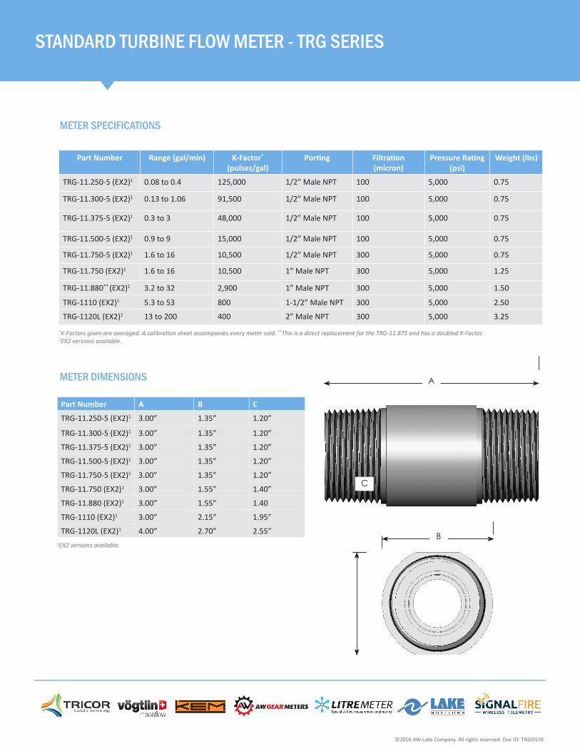
METER DIMENSIONS
Part Number A B C
TRG-11.250-5 (EX2)1 3.00” 1.35” 1.20”
TRG-11.300-5 (EX2)1 3.00” 1.35” 1.20”
TRG-11.375-5 (EX2)1 3.00” 1.35” 1.20”
TRG-11.500-5 (EX2)1 3.00” 1.35” 1.20”
TRG-11.750-5 (EX2)1 3.00” 1.35” 1.20”
TRG-11.750 (EX2)1 3.00” 1.55” 1.40”
TRG-11.880 (EX2)1 3.00” 1.55” 1.40
TRG-1110 (EX2)1 3.00” 2.15” 1.95”
TRG-1120L (EX2)1 4.00” 2.70” 2.55”
A
B
C
A
B
C
*K-Factors given are averaged. A calibration sheet accompanies every meter sold. **This is a direct replacement for the TRG-11.875 and has a doubled K-Factor. 1EX2 versions available.
©2016 AW-Lake Company. All rights reserved. Doc ID: TRGDS16
1EX2 versions available.
2440 W. Corporate Preserve Dr. #600, Oak Creek, WI 53154 | www.aw-lake.comawin-COMPANY
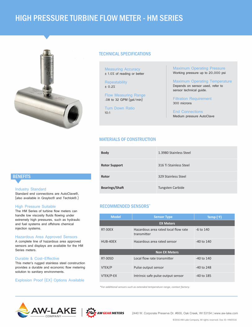
Industry StandardStandard end connections are AutoClave®, (also available in Grayloc® and Techlok®.)
High Pressure SuitableThe HM Series of turbine flow meters can handle low viscosity fluids flowing under extremely high pressures, such as hydraulic and fuel systems and offshore chemical injection systems.
Hazardous Area Approved SensorsA complete line of hazardous area approved sensors and displays are available for the HM Series meters.
Durable & Cost-EffectiveThis meter’s rugged stainless steel construction provides a durable and economic flow metering solution to sanitary environments.
Explosion Proof (EX) Options Available
BENEFITS
MATERIALS OF CONSTRUCTION
Body 1.3980 Stainless Steel
Rotor Support 316 Ti Stainless Steel
Rotor 329 Stainless Steel
Bearings/Shaft Tungsten Carbide
Maximum Operating PressureWorking pressure up to 20,000 psi
Maximum Operating TemperatureDepends on sensor used, refer to sensor technical guide.
Filtration Requirement300 microns
End ConnectionsMedium pressure AutoClave
Measuring Accuracy± 1.0% of reading or better
Repeatability± 0.2%
Flow Measuring Range.08 to 32 GPM (gal/min)
Turn Down Ratio10:1
HIGH PRESSURE TURBINE FLOW METER - HM SERIES
TECHNICAL SPECIFICATIONS
RECOMMENDED SENSORS*
Model Sensor Type Temp (°F)
EX Meters
RT-30EX Hazardous area rated local flow rate transmitter
-6 to 140
HUB-40EX Hazardous area rated sensor -40 to 140
Non EX Meters
RT-30SD Local flow rate transmitter -40 to 140
VTEK/P Pulse output sensor -40 to 248
VTEK/P-EX Intrinsic safe pulse output sensor -40 to 185
*For additional sensors such as extended temperature range, contact factory.
©2016 AW-Lake Company. All rights reserved. Doc ID: HMDS16
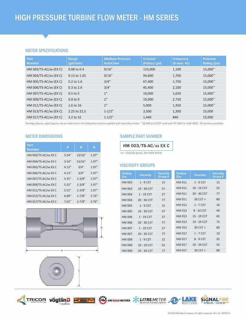
METER SPECIFICATIONS
HIGH PRESSURE TURBINE FLOW METER - HM SERIES
METER DIMENSIONS
*Average figures, exact figures can be taken from the calibration record supplied with each flow meter. **20,000 psi if NOT used with RT-30EX or HUB-40EX. EX versions available.
Part Number
Range (gal/min)
Medium Pressure AutoClave
K-Factor* (Pulses/ gal)
Frequency (0-max. Hz)
Pressure Rating (psi)
HM 003/TS-AC/xx (EX C) 0.08 to 0.4 9/16” 123,000 1,100 15,000**
HM 004/TS-AC/xx (EX C) 0.13 to 1.05 9/16” 94,600 1,700 15,000**
HM 005/TS-AC/xx (EX C) 0.2 to 1.6 3/4” 67,400 1,750 15,000**
HM 006/TS-AC/xx (EX C) 0.3 to 2.6 3/4” 45,400 2,100 15,000**
HM 007/TS-AC/xx (EX C) 0.5 to 5 1” 19,000 1,650 15,000**
HM 009/TS-AC/xx (EX C) 0.9 to 9 1” 19,000 2,750 15,000**
HM 011/TS-AC/xx (EX C) 1.6 to 16 1” 5,000 1,350 15,000**
HM 013/TS-AC/xx (EX C) 2.25 to 22.5 1-1/2” 3,500 1,300 15,000
HM 017/TS-AC/xx (EX C) 3.2 to 32 1-1/2” 1,440 840 15,000
A
B
D
Part Number A B D
HM 003/TS-AC/xx EX C 3.54” 13/16” 1.97”
HM 004/TS-AC/xx EX C 3.54” 13/16” 1.97”
HM 005/TS-AC/xx EX C 4.13” 3/4” 1.97”
HM 006/TS-AC/xx EX C 4.13” 3/4” 1.97”
HM 007/TS-AC/xx EX C 5.31” 1-3/8” 1.97”
HM 009/TS-AC/xx EX C 5.31” 1-3/8” 1.97”
HM 011/TS-AC/xx EX C 5.51” 1-3/8” 1.97”
HM 013/TS-AC/xx EX C 6.89” 1-7/8” 2.76”
HM 017/TS-AC/xx EX C 7.01” 1-7/8” 2.76”
©2016 AW-Lake Company. All rights reserved. Doc ID: HMDS16
Turbine Size Viscosity Viscosity
Group #
HM 003 1 - 9 CST 15
HM 003 10 - 30 CST 57
HM 004 1 - 19 CST 27
HM 004 20 - 30 CST 77
HM 005 1 - 9 CST 15
HM 005 10 - 30 CST 57
HM 006 1 - 19 CST 27
HM 006 20 - 30 CST 77
HM 007 1 - 19 CST 27
HM 007 20 - 30 CST 77
HM 009 1 - 9 CST 15
HM 009 10 - 19 CST 52
HM 009 20 - 30 CST 77
Turbine Size Viscosity Viscosity
Group #
HM 011 1 - 9 CST 15
HM 011 10 - 19 CST 52
HM 011 20 - 30 CST 77
HM 011 30 CST > 80
HM 013 1 - 7 CST 10
HM 013 8 - 14 CST 40
HM 013 15 - 19 CST 65
HM 013 19 - 29 CST 75
HM 013 30 CST > 80
HM 017 1 - 7 CST 10
HM 017 8 - 9 CST 35
HM 017 10 - 29 CST 55
HM 017 30 CST > 80
HM 003/TS-AC/xx EX C
VISCOSITY GROUPS
xx = viscosity group. See table below.
SAMPLE PART NUMBER
2440 W. Corporate Preserve Dr. #600, Oak Creek, WI 53154 | www.aw-lake.comCOMPANY
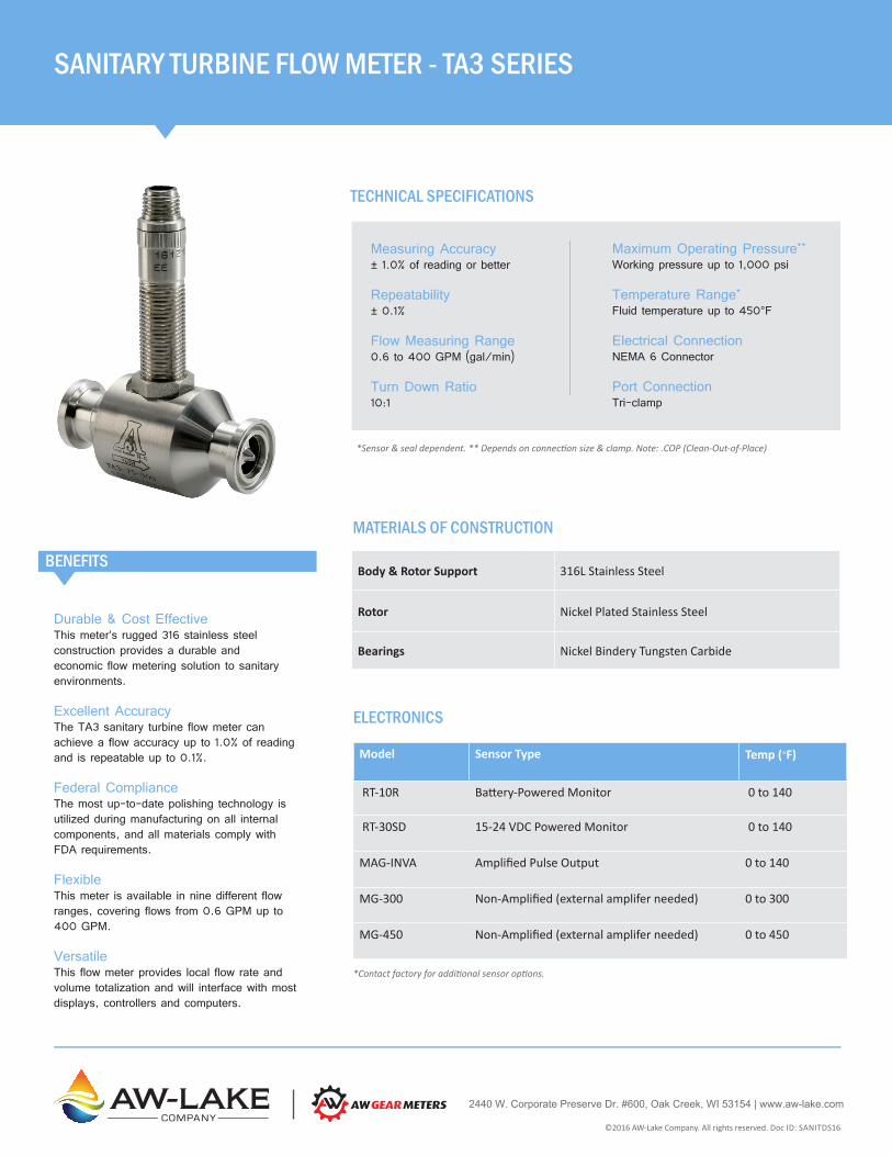
Durable & Cost EffectiveThis meter’s rugged 316 stainless steel construction provides a durable and economic flow metering solution to sanitary environments.
Excellent AccuracyThe TA3 sanitary turbine flow meter can achieve a flow accuracy up to 1.0% of reading and is repeatable up to 0.1%.
Federal ComplianceThe most up-to-date polishing technology is utilized during manufacturing on all internal components, and all materials comply with FDA requirements.
FlexibleThis meter is available in nine different flow ranges, covering flows from 0.6 GPM up to 400 GPM.
VersatileThis flow meter provides local flow rate and volume totalization and will interface with most displays, controllers and computers.
BENEFITS
MATERIALS OF CONSTRUCTION
Body & Rotor Support 316L Stainless Steel
Rotor Nickel Plated Stainless Steel
Bearings Nickel Bindery Tungsten Carbide
Maximum Operating Pressure**
Working pressure up to 1,000 psi
Temperature Range*
Fluid temperature up to 450°F
Electrical ConnectionNEMA 6 Connector
Port Connection Tri-clamp
Measuring Accuracy± 1.0% of reading or better
Repeatability± 0.1%
Flow Measuring Range0.6 to 400 GPM (gal/min)
Turn Down Ratio10:1
SANITARY TURBINE FLOW METER - TA3 SERIES
TECHNICAL SPECIFICATIONS
ELECTRONICS
*Sensor & seal dependent. ** Depends on connection size & clamp. Note: .COP (Clean-Out-of-Place)
Model Sensor Type Temp (°F)
RT-10R Battery-Powered Monitor 0 to 140
RT-30SD 15-24 VDC Powered Monitor 0 to 140
MAG-INVA Amplified Pulse Output 0 to 140
MG-300 Non-Amplified (external amplifer needed) 0 to 300
MG-450 Non-Amplified (external amplifer needed) 0 to 450
*Contact factory for additional sensor options.
©2016 AW-Lake Company. All rights reserved. Doc ID: SANITDS16
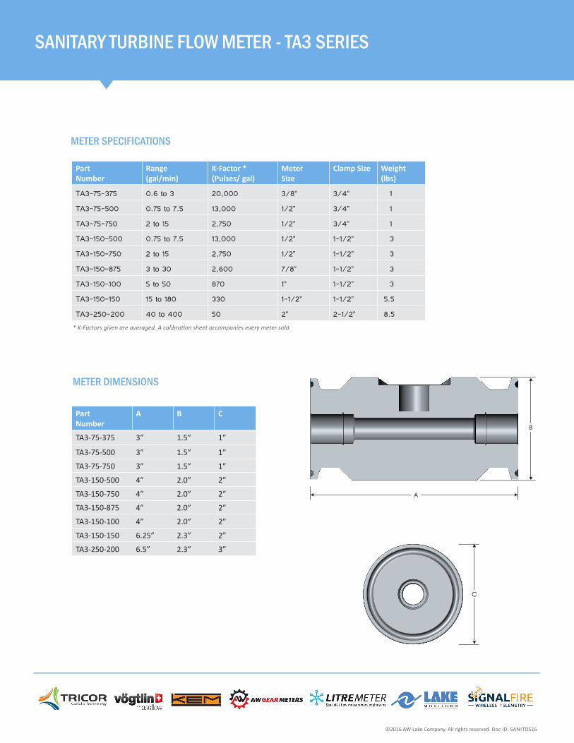
SANITARY TURBINE FLOW METER - TA3 SERIES
METER SPECIFICATIONS
Part Number
Range (gal/min)
K-Factor * (Pulses/ gal)
Meter Size
Clamp Size Weight (lbs)
TA3-75-375 0.6 to 3 20,000 3/8” 3/4” 1
TA3-75-500 0.75 to 7.5 13,000 1/2” 3/4” 1
TA3-75-750 2 to 15 2,750 1/2” 3/4” 1
TA3-150-500 0.75 to 7.5 13,000 1/2” 1-1/2” 3
TA3-150-750 2 to 15 2,750 1/2” 1-1/2” 3
TA3-150-875 3 to 30 2,600 7/8” 1-1/2” 3
TA3-150-100 5 to 50 870 1” 1-1/2” 3
TA3-150-150 15 to 180 330 1-1/2” 1-1/2” 5.5
TA3-250-200 40 to 400 50 2” 2-1/2” 8.5* K-Factors given are averaged. A calibration sheet accompanies every meter sold.
METER DIMENSIONS
Part Number
A B C
TA3-75-375 3″ 1.5″ 1″
TA3-75-500 3″ 1.5″ 1″
TA3-75-750 3″ 1.5″ 1″
TA3-150-500 4″ 2.0″ 2″
TA3-150-750 4″ 2.0″ 2″
TA3-150-875 4″ 2.0″ 2″
TA3-150-100 4″ 2.0″ 2″
TA3-150-150 6.25″ 2.3″ 2″
TA3-250-200 6.5″ 2.3″ 3″
A
B
C
©2016 AW-Lake Company. All rights reserved. Doc ID: SANITDS16

2440 W. Corporate Preserve Dr. #600, Oak Creek, WI 53154 | www.aw-lake.comawinforCOMPANY
Fast Response Time & High ResolutionThe Turbine wheel’s low moment of inertia allows a fast acceleration from standstill up to full number of revolutions within 5 to 50 sec. For that reason, dynamic measurements can be made. The resolution can amount to as much as 35,000 pulses per liter.
Wide Temperature RangeStandard turbine: -4 up to 248°F Special models for cryogenic liquids: -459°F Special models w/ hi-temp pickups: up to 662°F.
Low Contamination RiskThe spacing of the turbine wheel and bearing mount is wide enough to protect against particles in fluid jamming the turbine wheel. And the Twist of flow in this area has a self-cleaning effect for the bearing.
BENEFITS
MATERIALS OF CONSTRUCTION
Body 316 Stainless Steel Ti / 316L
Rotor Support 316 Stainless Steel Ti
Rotor 429 Stainless Steel / 329
Bearings Tungsten Carbide with Nickel binder
Maximum Operating PressureWorking pressure is flange dependent
Maximum Operating TemperatureFluid temperature of -384° to 662°F
Filtration Requirement300 microns
End ConnectionsEquipped with flanges as per DIN or ANSI
Measuring Accuracy± 1.0% of reading or better
Repeatability± 0.2%
Flow Measuring Range.008 to 12,000 GPM (gal/min)
Turn Down Ratio10:1
TECHNICAL SPECIFICATIONS
SENSOR OPTIONS
Model Sensor Type Temp (°F)
VTEK/P Pulse output sensor -150 to 325
VTEK/P -EX Pulse output sensor -40 to 185
RT-30SD Local flow rate transmitter -40 to 140
RT-30EX Hazardous area rated local flow rate transmitter
* For additional sensors available, contact factory.
©2016 AW-Lake Company. All rights reserved. Doc ID: HMFDS090816
FLANGED TURBINE FLOW METER - HM-F SERIES
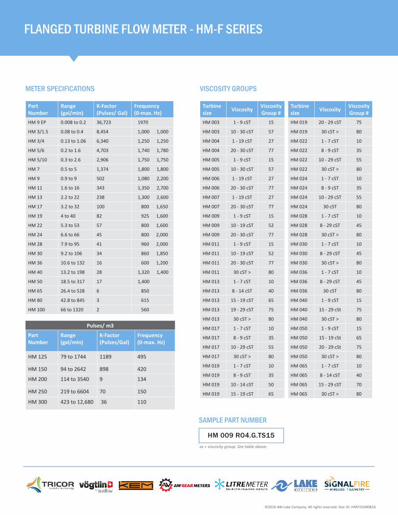
METER SPECIFICATIONS
FLANGED TURBINE FLOW METER - HM-F SERIES
Part Number
Range (gal/min)
K-Factor (Pulses/ Gal)
Frequency (0-max. Hz)
HM 9 EP 0.008 to 0.2 36,723 1970
HM 3/1.5 0.08 to 0.4 8,454 1,000 1,000
HM 3/4 0.13 to 1.06 6,340 1,250 1,250
HM 5/6 0.2 to 1.6 4,703 1,740 1,780
HM 5/10 0.3 to 2.6 2,906 1,750 1,750
HM 7 0.5 to 5 1,374 1,800 1,800
HM 9 0.9 to 9 502 1,080 2,200
HM 11 1.6 to 16 343 1,350 2,700
HM 13 2.2 to 22 238 1,300 2,600
HM 17 3.2 to 32 100 800 1,650
HM 19 4 to 40 82 925 1,600
HM 22 5.3 to 53 57 800 1,600
HM 24 6.6 to 66 45 800 2,000
HM 28 7.9 to 95 41 960 2,000
HM 30 9.2 to 106 34 860 1,850
HM 36 10.6 to 132 16 600 1,200
HM 40 13.2 to 198 28 1,320 1,400
HM 50 18.5 to 317 17 1,400
HM 65 26.4 to 528 6 850
HM 80 42.8 to 845 3 615
HM 100 66 to 1320 2 560
Pulses/ m3
Part Number
Range (gal/min)
K-Factor(Pulses/Gal)
Frequency (0-max. Hz)
HM 125 79 to 1744 1189 495
HM 150 94 to 2642 898 420
HM 200 114 to 3540 9 134
HM 250 219 to 6604 70 150
HM 300 423 to 12,680 36 110
©2016 AW-Lake Company. All rights reserved. Doc ID: HMFDS090816
Turbine size Viscosity Viscosity
Group #HM 003 1 - 9 cST 15
HM 003 10 - 30 cST 57
HM 004 1 - 19 cST 27
HM 004 20 - 30 cST 77
HM 005 1 - 9 cST 15
HM 005 10 - 30 cST 57
HM 006 1 - 19 cST 27
HM 006 20 - 30 cST 77
HM 007 1 - 19 cST 27
HM 007 20 - 30 cST 77
HM 009 1 - 9 cST 15
HM 009 10 - 19 cST 52
HM 009 20 - 30 cST 77
HM 011 1 - 9 cST 15
HM 011 10 - 19 cST 52
HM 011 20 - 30 cST 77
HM 011 30 cST > 80
HM 013 1 - 7 cST 10
HM 013 8 - 14 cST 40
HM 013 15 - 19 cST 65
HM 013 19 - 29 cST 75
HM 013 30 cST > 80
HM 017 1 - 7 cST 10
HM 017 8 - 9 cST 35
HM 017 10 - 29 cST 55
HM 017 30 cST > 80
HM 019 1 - 7 cST 10
HM 019 8 - 9 cST 35
HM 019 10 - 14 cST 50
HM 019 15 - 19 cST 65
Turbine size Viscosity Viscosity
Group #HM 019 20 - 29 cST 75
HM 019 30 cST > 80
HM 022 1 - 7 cST 10
HM 022 8 - 9 cST 35
HM 022 10 - 29 cST 55
HM 022 30 cST > 80
HM 024 1 - 7 cST 10
HM 024 8 - 9 cST 35
HM 024 10 - 29 cST 55
HM 024 30 cST 80
HM 028 1 - 7 cST 10
HM 028 8 - 29 cST 45
HM 028 30 cST > 80
HM 030 1 - 7 cST 10
HM 030 8 - 29 cST 45
HM 030 30 cST > 80
HM 036 1 - 7 cST 10
HM 036 8 - 29 cST 45
HM 036 30 cST 80
HM 040 1 - 9 cST 15
HM 040 15 - 29 cSt 75
HM 040 30 cST > 80
HM 050 1 - 9 cST 15
HM 050 15 - 19 cSt 65
HM 050 20 - 29 cSt 75
HM 050 30 cST > 80
HM 065 1 - 7 cST 10
HM 065 8 - 14 cST 40
HM 065 15 - 29 cST 70
HM 065 30 cST > 80
VISCOSITY GROUPS
HM 009 RO4.G.TS15xx = viscosity group. See table above.
SAMPLE PART NUMBER

2440 W. Corporate Preserve Dr. #600, Oak Creek, WI 53154 | www.aw-lake.comawinforCOMPANY
Made for Subsea EnvironmentDesigned to withstand the harsh subsea environment, there is no need for a pressurized container.
Sealed ElectronicCompletely sealed electronics, there is no need for subsea electronics module canister space.
VersatileAvailable in multiple flow ranges.
CustomizableOur engineers will work with you on customized materials or port configurations to meet your specific application requirements.
Rugged ConstructionThe sturdy construction of this turbine flow meter means high performance and longer service life.
BENEFITS
MATERIALS OF CONSTRUCTION
Body & Rotor Support 316 Ti
Rotor 329 Stainless Steel
Bearings Tungsten Carbide
Process ConnectionAutoclave*
Temperature Range-40˚ to 250˚F (-40˚ to 121˚C)
Electrical Connections6-pin receptacle (or customer specified for custom meters).
OutputAmplified pulse or 4-20mA output.
Measuring Accuracy± 1.0% of reading or better
Flow Measuring RangeUp to 16 GPM (gal/min)
External PressureUp to 7,200 psi
Maximum Operating PressureUp to 20,000 psi
SUBSEA TURBINE FLOW METERIdeal for Subsea Applications such as Valve Actuation & Testing on Subsea Equipment and ROVs.
TECHNICAL SPECIFICATIONS
TRANSMITTER
Supply voltage +7 up to 29 VDC
Quiescent Current < 5 mA
Frequency Range 2 up to 2,000 Hz
Ambient Temperature -40 to 250°F (-40 to 121°C)
Housing 316 Ti
Electrical Connection 6-pin receptacle no. 1370046-101*
*Contact factory for addional options.
*Other options available upon request.
©2016 AW-Lake Company. All rights reserved. Doc ID: SUBSEADS16
METER SPECIFICATIONS
Part Number Range (gal/min) Connections Operating Pressure Overall Length Meter Dimensions
HM-003/AC-71-9/16”-C1-TC01-S01 0.08 to 0.4 9/16” Autoclave 20,000 PSI 3.5 Inch 2 in X 3.50 in
HM-009/AC-71-1”-C1-TC01-S01 0.87 to 8.72 1” Autoclave 20,000 PSI 5.3 Inch 2 in X 3.50 in
HM-011/AC-71-1”-C1-TC01-S01 1.5 to 15.8 1” Autoclave 10,000 PSI 5.5 Inch 2 in X 3.50 in
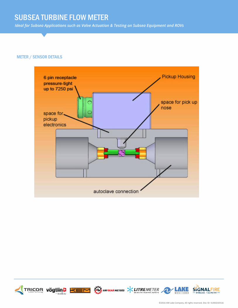
SUBSEA TURBINE FLOW METERIdeal for Subsea Applications such as Valve Actuation & Testing on Subsea Equipment and ROVs
©2016 AW-Lake Company. All rights reserved. Doc ID: SUBSEADS16
METER / SENSOR DETAILS

2440 W. Corporate Preserve Dr. #600, Oak Creek, WI 53154 | www.aw-lake.comawinforCOMPANY
Accurate & ReaptableThe TR Series turbine meter is accurate to ±1% of reading with repeatability of better than ±0.1%.
Smart & Simple DesignUnique design eliminates the need for matingflanges, resulting in lower costs and simplifyinginstallation.
Space-SaverWafer-style mounting configurations for limitedspace requirements.
High PerformanceThis flow meter is made from superior materials of construction for high performance in aggressive environments.
Improved AccuracyThe modiffied upstream and downstream flowstraighteners allow for a higher accuracy andgreater fluid dynamics.
BENEFITS
MATERIALS OF CONSTRUCTION
Body & Rotor Support 316 Stainless Steel
Bearings Tungsten Carbide
Rotor Stainless Steel
Rotor Shaft Tungsten Carbide
Maximum Operating PressureRefer to ASME/ANSI B16.5-1996
Maximum Operating TemperatureFluid temperature of -150° to 300°F
End ConnectionsWafer-style ASME/ANSI B16.5-1996• Threaded, Flange, Graloc & Victaulic
Measuring Accuracy± 1.0% of reading or better
Repeatability± 0.1%
Flow Measuring Range.05 to 5,000 GPM (gal/min) (per flange rating of install kit)
TURBINE FLOW METER - TR-QS SERIES
TECHNICAL SPECIFICATIONS
INSTALLATION KITS
Size 150# 300# 600# 900# 1500#
1” TR-1110QS-150 TR-1110QS-300 TR-1110QS-600 TR-1110QS-900 call factory
2” TR-1120QS-150 TR-1120QS-300 TR-1120QS-600 TR-1120QS-900 call factory
3” TR-1130QS-150 TR-1130QS-300 TR-1130QS-600 TR-1130QS-900 call factory
4” TR-1140QS-150 TR-1140QS-300 TR-1140QS-600 TR-1140QS-900 call factory
6” TR-1160QS-150 TR-1160QS-300 TR-1160QS-600 TR-1160QS-900 call factory
8” TR-1180QS-150 TR-1180QS-300 TR-1180QS-600 TR-1180QS-900 call factory
10” TR-1190QS-150 TR-1190QS-300 TR-1190QS-600 TR-1190QS-900 call factory
Each kit includes studs, nuts, gaskets and spacer rings.
*Actual pressure rating depends on installtion connection.
©2016 AW-Lake Company. All rights reserved. Doc ID: TRQSDS16
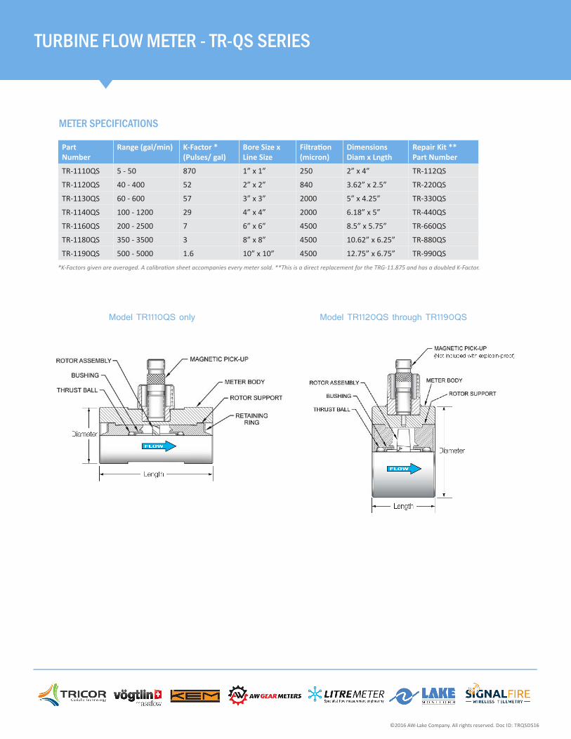
METER SPECIFICATIONS
TURBINE FLOW METER - TR-QS SERIES
Part Number
Range (gal/min) K-Factor * (Pulses/ gal)
Bore Size x Line Size
Filtration (micron)
Dimensions Diam x Lngth
Repair Kit ** Part Number
TR-1110QS 5 - 50 870 1” x 1” 250 2” x 4” TR-112QS
TR-1120QS 40 - 400 52 2” x 2” 840 3.62” x 2.5” TR-220QS
TR-1130QS 60 - 600 57 3” x 3” 2000 5” x 4.25” TR-330QS
TR-1140QS 100 - 1200 29 4” x 4” 2000 6.18” x 5” TR-440QS
TR-1160QS 200 - 2500 7 6” x 6” 4500 8.5” x 5.75” TR-660QS
TR-1180QS 350 - 3500 3 8” x 8” 4500 10.62” x 6.25” TR-880QS
TR-1190QS 500 - 5000 1.6 10” x 10” 4500 12.75” x 6.75” TR-990QS
Model TR1110QS only Model TR1120QS through TR1190QS
©2016 AW-Lake Company. All rights reserved. Doc ID: TRQSDS16
*K-Factors given are averaged. A calibration sheet accompanies every meter sold. **This is a direct replacement for the TRG-11.875 and has a doubled K-Factor.