GAS GRIDDLE PLATES 900 Series - Metosmetos.com/pdf/prods/userguide/EN/4370008.pdf · GAS GRIDDLE...
42
GAS GRIDDLE PLATES 900 Series MODELLO CON RUBINETTO MODELLO CON VALVOLA TYPE: 92/04FTG, 92/04FTGR, 94/04FTG, 94/04FTG1/2R, 94/04FTGR, 92/04FTTG, 92/04FTTGR, 92/04FTTGC, 92/04FTTGCR, 94/04FTTG, 94/04FTTG1/2R, 94/04FTTGC, 94/04FTTGC1/2R, 94/04FTTGCR, 92/04TFTG, 92/04TFTGR, 94/04TFTG, 94/04TFTG1/2R, 94/04TFTGR, 92/04TFTTG, 92/04TFTTGR, 92/04TFTTGC, 92/04TFTTGCR, 94/04TFTTG, 94/04TFTTG1/2R, 94/04TFTTGC, 94/04TFTTGC1/2R, 94/04TFTTGCR User Manual S/N: Valid from:11. 10. 2004 Rev.: 1.0
Transcript of GAS GRIDDLE PLATES 900 Series - Metosmetos.com/pdf/prods/userguide/EN/4370008.pdf · GAS GRIDDLE...

GAS GRIDDLE PLATES 900 Series
MODELLO CON RUBINETTOMODELLO CON VALVOLA
TYPE: 92/04FTG, 92/04FTGR, 94/04FTG, 94/04FTG1/2R, 94/04FTGR, 92/04FTTG, 92/04FTTGR, 92/04FTTGC, 92/04FTTGCR, 94/04FTTG, 94/04FTTG1/2R, 94/04FTTGC,
94/04FTTGC1/2R, 94/04FTTGCR, 92/04TFTG, 92/04TFTGR, 94/04TFTG, 94/04TFTG1/2R, 94/04TFTGR, 92/04TFTTG, 92/04TFTTGR, 92/04TFTTGC, 92/04TFTTGCR, 94/04TFTTG,
94/04TFTTG1/2R, 94/04TFTTGC, 94/04TFTTGC1/2R, 94/04TFTTGCR
User Manual
S/N: Valid from:11. 10. 2004 Rev.: 1.0


12.10.2004 Rev.
Dear Customer,
Congratulations on deciding to choose a Metos appliance for your kitchen activities. Youmade an excellent choice. We will do our best to make you a satisfied Metos customerlike thousands of customers we have around the world.
Please read this manual carefully. You will learn correct, safe and efficient working meth-ods in order to get the best possible benefit from the appliance. The instructions and hintsin this manual will give you a quick and easy start, and you will soon note how nice it isto use the Metos equipment.
All rights are reserved for technical changes.
You will find the main technical data on the rating plate fixed to the equipment. When youneed service or technical help, please let us know the serial number shown on the ratingplate. This will make it easier to provide you with correct service.
For your convenience, space is provided below for you to record your local Metos servicecontact information.
METOS TEAM
Metos service phone number:...............................................................................................
Contact person:....................................................................................................................

12.10.2004 Rev.

12.10.2004 Rev.
1. General information ..................................................................................... 11.1 Symbols used in the manual .......................................................................................... 11.2 Symbols used on the appliance ...................................................................................... 21.3 Checking the relationship of the appliance and the manual .......................................... 2
2. Safety .............................................................................................................. 32.1 Using the appliance safely ............................................................................................. 32.2 Safety instructions in case of malfunction ..................................................................... 32.3 Additional prohibitions (hazardous procedures) ........................................................... 32.4 Disposing of the appliance ............................................................................................ 3
3. Functional description .................................................................................. 43.1 Application of the appliance .......................................................................................... 4
3.1.1 Prohibited use ........................................................................................................ 43.2 Construction .................................................................................................................. 43.3 Operating principle ........................................................................................................ 4
4. Operating instructions ................................................................................. 54.1 Before using the appliance ............................................................................................ 5
4.1.1 Preparing the appliance for use .............................................................................. 54.2 Using the appliance ....................................................................................................... 6
4.2.1 Lighting the pilot flame ......................................................................................... 64.2.2 Lighting the main burner in models with smooth chrome-plated griddle plate (fry top with valve) ................................................................................................................ 84.2.3 Cooking ................................................................................................................. 84.2.4 Turning off the appliance ....................................................................................... 84.2.5 Safety thermostat ................................................................................................... 9
4.3 After-use care .............................................................................................................. 104.3.1 Cleaning ............................................................................................................... 104.3.2 Periodic maintenance ........................................................................................... 12
5. Installation ................................................................................................... 135.1 General information ..................................................................................................... 135.2 Regulatory installation conditions ............................................................................... 135.3 Exhausting fumes ........................................................................................................ 135.4 Possible environmental interference ............................................................................ 145.5 Storage ......................................................................................................................... 145.6 Unpacking the appliance ............................................................................................. 145.7 Disposing of packaging materials ............................................................................... 14

12.10.2004 Rev.
5.8 Positioning ................................................................................................................... 145.9 Gas supply connection ................................................................................................. 15
5.9.1 Checking supply pressure after installation ......................................................... 175.9.2 Gas technical specifications ................................................................................. 185.9.3 Checking operation .............................................................................................. 20
5.10 Staff training .............................................................................................................. 205.11 Rating plate ................................................................................................................ 20
6. Adjustment instructions ............................................................................ 216.1 Removing the control panel ......................................................................................... 216.2 Adjusting the minimum setting ................................................................................... 226.3 Replacing the main burner nozzle ............................................................................... 236.4 Adjusting the primary air ............................................................................................. 236.5 Replacing the pilot flame burner nozzle ...................................................................... 246.6 Checking operations .................................................................................................... 24
7. Troubleshooting .......................................................................................... 25
9. Technical specifications .............................................................................. 41
12.10.2004 Rev. 1.0General information
1. General information
Carefully read the instructions in this manual as they contain important information re-garding proper, efficient and safe installation, use and maintenance of the appliance.
Keep this manual in a safe place so that it can be used as reference by other operators ofthe appliance.
The installation of this appliance must be carried out in accordance with the manufactur-er’s instructions and following local regulations. The connection of the appliance to thesupplies must be carried out by qualified personnel only.
Personnel using this appliance should be specifically trained in its operation.
Switch off the appliance in the case of failure or malfunction. The periodical functionchecks requested in the manual must be carried out according to the instructions. Have theappliance serviced by a technically qualified person authorized by the manufacturer andusing original spare parts.
Not complying with the above may put the safety of the appliance in danger.
1.1 Symbols used in the manual
This symbol informs about a situation where a safety risk might be at hand. Given instruc-tions are mandatory in order to prevent injury.
This symbol informs about the right way to perform in order to prevent bad results, appli-ance damage or hazardous situations.
This symbol informs about recommendations and hints that help to get the best perform-ance out of the appliance.
This symbol informs about a function that has to be taken into account in self-control.
1

12.10.2004 Rev. 1.0General information
1.2 Symbols used on the appliance
This symbol on a part informs about electrical terminals behind the part. The removal ofthe part must be carried out by qualified personnel only.
1.3 Checking the relationship of the appliance and the manual
The rating plate of the appliance indicates the serial number of the appliance. If the man-uals are missing, it is possible to order new ones from the manufacturer or the local rep-resentative. When ordering new manuals it is essential to quote the serial number shownon the rating plate.
2

12.10.2004 Rev. 1.0Safety
2. Safety
2.1 Using the appliance safely
Being an appliance designed only for professional use, it should be operated by qualifiedpersonnel exclusively. Never leave the appliance unattended while it is on.
Ensure compliance with all safety and fire regulations in force in the location where theappliance is being installed.
Do not move the appliance while it is still hot!
During operation, the grease drawer should always be installed.
IF OIL SHOULD CATCH FIRE, NEVER USE WATER TO EXTINGUISH IT.
2.2 Safety instructions in case of malfunction
If oil should catch fire, use a fire extinguisher or a suitable self-extinguishing fire blanketto smother the fire.
2.3 Additional prohibitions (hazardous procedures)
Never tamper with the seals of the adjusting screws located on the gas valves.
2.4 Disposing of the appliance
This appliance was manufactured using recyclable raw materials and does not contain anyhazardous or toxic substances. Dispose of the appliance in full compliance with all appli-cable local regulations in force in the place where the appliance is being used. Packagingmaterials should be divided according to type and delivered to a specific collection site.Ensure compliance with environmental protection regulations.
3

12.10.2004 Rev. 1.0Functional description
3. Functional description
3.1 Application of the appliance
The intended use of the appliance is to cook raw food on the griddle plate. The griddleplate transmits heat to raw food giving a special surface according to the type of oil,grease, smooth or ribbed griddle plate used.
3.1.1 Prohibited use
The appliance is not designed to heat pots and pans as if it were an electric range.
3.2 Construction
Steel or polished chrome-plated griddle with:
• side and back splashback; • grease trough with drain hole; • removable grease drawer.
The appliance is equipped with gas burners controlled by thermostatic safety valves withthermocouple and piezoelectric ignition.
Models 74 have two heating zones whose temperature can be separately controlled.
3.3 Operating principle
The gas burners located underneath the griddle plate heat the cooking surface to the de-sired temperature.
The heating surface will close the surface fibres of meat, thus capturing the juices within.In this way you can prepare delicious dishes.
4

12.10.2004 Rev. 1.0Operating instructions
4. Operating instructions
4.1 Before using the appliance
4.1.1 Preparing the appliance for use
Remove all packaging materials and self-adhesive plastic film from the appliance, beingcareful not to leave any glue traces on the steel surface. If necessary, remove any glue trac-es left using non-flammable solvents.
Prior to cooking for the first time, we recommend cleaning the appliance thoroughly, andespecially the griddle plate, using hot water and a sponge. Empty all cleaning water outof the grease drawer.
Before cleaning any stainless steel parts, make sure that the detergent you intend to usedoes not contain any abrasive substances and that it is suitable for stainless steel surfaces.
After having cleaned the appliance, rinse it with clean water, wipe it dry with a clean clothand spread a thin film of edible oil over the griddle plate in order to prevent rust fromforming.
Never use water jets to clean the appliance.
5

12.10.2004 Rev. 1.0Operating instructions
4.2 Using the appliance
4.2.1 Lighting the pilot flame
Fry-top with tap
Push the knob (item 2 in Fig. 1) and turn it towards the left to the position shown item 4in Fig. 1. Press and hold down the knob and at the same time push the ignition button (item1). After lighting the pilot flame, hold the knob down for 15-20 seconds to allow the ther-mocouple to heat. If the pilot flame goes out, repeat the lighting process.
Fig. 11. Piezoelectric ignition2. Gas valve knob3. OFF position4. Pilot flame ignition5. “Maximum” position6. “Minimum” position
Lighting the main burner (models with tap)
To light the main burner, exercise a slight pressure and turn the knob to the “maximum”or “minimum” position (pos. 5 o pos. 6 in Fig.1).
6

12.10.2004 Rev. 1.0Operating instructions
Fry top with valve
Push the knob (item 1 in Fig. 1) and turn it towards the left to the position shown as item6 in Fig. 1. Press and hold down the knob and at the same time push the ignition button(item 2). After lighting the pilot flame, hold the knob down for 10-15 seconds to allow thethermocouple to heat. If the pilot flame goes out, repeat the lighting process.
Proper pilot flame lighting can be checked through the inspection hole (item 3) especiallyprovided for that purpose.
Fig. 21. Gas valve knob2. Piezoelectric ignition3. Pilot flame inspection hole4. Grease drawer 5. OFF position6. Pilot flame lit7. Low temperature 8. High temperature
7

12.10.2004 Rev. 1.0Operating instructions
4.2.2 Lighting the main burner in models with smooth chrome-plated griddle plate (frytop with valve)
To light the main burner, exercise a slight pressure and turn the knob to the position cor-responding to the desired temperature (between item 7 and item 8 in Fig. 1). Griddle platetemperature will be maintained at the set value by means of a thermostatic valve that au-tomatically turns the main burner on and off.
Temperature of chrome-plated griddle plates can be set between 120°C (248°F) and250°C (482°F) and to any value in between.
The table below shows the average temperature of the griddle plate for each knob posi-tion:
4.2.3 Cooking
• Use the knob to set the desired cooking temperature; • spread an even layer of oil or fat over the griddle plate; • place the products on the griddle plate; • when the lower part of the product is cooked to the desired degree, turn it over and
cook the other side; • once both sides are grilled, lower the temperature and leave the products on the
plate until completely done.
Never leave the appliance unattended while it is on.
On chrome-plated griddle plates, use only wooden or heat-resistant plastic kitchen uten-sils to turn food over.
4.2.4 Turning off the appliance
To turn off the main burner, turn the knob towards the right to the position shown by item4 in Fig. 1 (or fig.2): only the pilot flame will remain lit. Exercise a slight pressure andturn the knob to the position shown as item 3 to extinguish the pilot flame too.
The griddle plate can still be burning hot.
Position 1 2 3 4 5 6 7°C (°F) 120
(248)140
(284)165
(329)195
(383)215
(419)240
(464)250
(482)
8

12.10.2004 Rev. 1.0Operating instructions
4.2.5 Safety thermostat
This appliance is equipped with a safety thermostat. When the safety thermostat trips, itavoids hot plate overheating, which could result in fire hazard. This is a safety precautionwhich trips if a component is faulty or if the appliance is used incorrectly (water in thetank below the minimum level, dirty immersion heaters, etc.).
If the safety thermostat trips, proceed as follows for resetting:
• remove the control panel (as shown in the related chapter);• press the button to reset (item 1 Fig. 2a) until you hear a metal click.
Fig. 2a1. Button for resetting the safety thermostat2. Safety thermostat
9

12.10.2004 Rev. 1.0Operating instructions
4.3 After-use care
4.3.1 Cleaning
Prior to cleaning, turn off the appliance and the shutoff gas valve on the supply line up-stream of the appliance.
General information
The main causes for stainless steel wear or corrosion are:
• using abrasive or acid detergents, especially chlorine-based products such as hy-drochloric acid or sodium hypochlorite (bleach). Therefore, before buying a clean-ing product, make sure it does not corrode stainless steel (see also paragraph"Routine cleaning" further below);
• stagnation of ferrous deposits (such as those created by rust dissolved in the waterflowing through the piping, especially after the appliance has remained idle forsome time). Therefore, avoid such stagnation. Do not use wire wool pads to re-move the most stubborn food residues. Use, rather, pads or spatulas made of stain-less steel or softer, non-ferrous materials;
• stagnation of substances having acid components such as vinegar, lemon juice,sauces, salt, etc. Avoid prolonged contact of the stainless steel parts of the appli-ance with those substances. The evaporation of saline solutions over the surfacesof the appliance is particularly harmful to them.
Routine cleaning
Cleaning the appliance thoroughly on a daily basis is the key to keeping it in perfect work-ing condition and prolonging its life. Let the appliance cool down before cleaning it, butremember to clean the griddle plate while it is still warm.
Pull out the grease drawer and empty it into a suitable container. Clean the drawer thor-oughly and wipe it dry.
Clean the appliance with a damp cloth using water and soap or detergents, provided thatthey are not acid or abrasive as discussed further above. Such detergents should not evenbe used to wash the floor near the appliance, as their fumes may deposit on the steel sur-faces and damage them. If the appliance is very dirty, use a Scotch-BriteTM type syntheticscrub sponge. Rinse it off with clean water and wipe it dry with a clean cloth. Do not rubthe appliance with steel wool pads as they could leave rust stains. For the same reason,avoid touching the appliance with ferrous objects.
In order to prevent corrosion spots from forming, ensure that any salt residues left on thesides of the worktop and on the griddle plate are carefully removed.
Never use direct water jets to clean the appliance because this could result in water enter-ing into it and damaging it.
10
12.10.2004 Rev. 1.0Operating instructions
Cleaning cast-iron griddle plates
It is advisable to clean the griddle plate after use, while it is still relatively warm, usingsandpaper or steel wool pads. After cleaning, spread a thin film of edible oil over the entiregriddle plate surface in order to prevent rust from forming.
Cleaning chrome-plated griddle plates
To obtain excellent cooking results out of your chrome-plated griddle plate, carry out thefollowing cleaning operations:
• once you have finished cooking, remove any food residues left on the griddle platewhile it is still warm using the spatula supplied. Finally, eliminate any marks lefton the surface using a damp cloth;
• repeat the above mentioned procedures as many times as required. If not removed,food residues left on the griddle plate can burn and contaminate the products to becooked in subsequent cycles;
• spread a thin film of edible oil over the entire griddle plate.
Do not use any pointed utensils to remove food while cooking as they can damage thegriddle plate.
Stains and abrasions on the steel surfaces
Scratches may be smoothed or removed using stainless steel wool pads or synthetic abra-sive sponges, which should always be rubbed in the same direction as the satin finish.
Rust
Should you need to eliminate rust stains, contact manufacturers of industrial detergents tofind a suitable product. For this purpose, you may also use industrial descaling products.After removing the stain and rinsing off the appliance with clean water, an alkaline deter-gent may be required to neutralize any acid compounds left on the surface.
Idle period
If the appliance will remain idle for a certain period of time, clean it and wipe it dry first,and then apply a film of a suitable product (such as vaseline oil spray or similar products)to protect it.
Turn off the gas shutoff valve fitted upstream of the appliance.
11

12.10.2004 Rev. 1.0Operating instructions
4.3.2 Periodic maintenance
Only qualified personnel are allowed to carry out service and maintenance operations.
The following maintenance operation should be carried out at least once a year:
• checking for proper operation of all control and safety devices;• checking combustion, i.e.:
1. lighting; 2. combustion safety;3. checking for proper operation throughout the ON-OFF-ON control range;
We recommend signing a service agreement providing for at least one check-up a year.
12
12.10.2004 Rev. 1.0Installation
5. Installation
5.1 General information
The manufacturer cannot be held liable for any injuries to persons or damage to propertyresulting from installation errors or from inappropriate use of the appliance and is not re-sponsible for any faults caused by defective installation. In such cases, the warranty shallbe null and void.
Installation, maintenance, connection to gas supply and start-up should all be performedby an authorised installer who must ensure compliance with all applicable safety regula-tions in force in the location where the appliance is being installed.
5.2 Regulatory installation conditions
We remind you that all appliances installed in public assembly buildings must meet therequirements specified below. The appliance must be both installed and serviced in com-pliance with all applicable rules and legal regulations in force, namely:
• safety regulations on fire hazard and panic in public assembly buildings;• general regulations applicable to all appliances;• systems burning combustible gas and liquefied hydrocarbons.
Then, follow the specific regulations according to the type of gas being used.
• heating, ventilation, refrigeration, air conditioning, and generation of steam andhot water for sanitary use;
• installation of foodservice cooking appliances;• specific regulations applicable to each type of public assembly building (hospitals,
shops, etc.).
5.3 Exhausting fumes
The appliance should be installed in a well-ventilated area, if possible under an exhausthood, in compliance with all applicable regulations in force. This will ensure that all burntgases produced during the combustion process are completely exhausted. The amount ofair required for combustion is shown in the “Technical specifications table” at the end ofthis manual, under "Air required for combustion".
In compliance with applicable installation regulations in force, our appliances belong tothe type shown under "Construction type" in the "Technical specifications table".
13

12.10.2004 Rev. 1.0Installation
5.4 Possible environmental interference
If the appliance is installed with its sides next to flammable walls (made of wood or sim-ilar materials) or to heat-sensitive walls (made of plasterboard or similar materials), suit-able protective measures should be taken to keep such walls undamaged. Either apply acoating to insulate the appliance from radiative heat or keep a minimum clearance of 100mm (4") from the sides and 50 mm (2") from the back of the appliance.
5.5 Storage
If the appliance is stored in a warehouse whose room temperature is below 0°C (32°F),warm the appliance up to at least +10°C (50°F) prior to turning it on.
5.6 Unpacking the appliance
Prior to installation, remove all packaging materials from the appliance. Some parts arewrapped in self-adhesive film, which should be thoroughly removed. Remove any gluetraces carefully using a suitable non-flammable solvent. Absolutely avoid using abrasivesubstances.
5.7 Disposing of packaging materials
All packaging materials must be disposed of in compliance with applicable local regula-tions in force where the appliance is being installed. Packaging materials should be sepa-rated according to their type and delivered to specific collection sites. Ensure compliancewith environmental protection regulations.
5.8 Positioning
Freestanding models:level the appliance using a bubble level. Small adjustments can bemade using the height-adjustable feet.
Countertop models:if you install the griddle plate on a base, tighten the feet into theinnermost threads. In this way, the appliance will remain firmly secured.
14

12.10.2004 Rev. 1.0Installation
5.9 Gas supply connection
This appliance is designed to burn natural and liquid gas. To find out the category towhich this appliance belongs in the country where it is installed, please refer to the tablebelow.
Table 1: gas categories and pressure values
COUNTRY APPLIANCE CATEGORY GAS RATED PRES-
SURE (mbar)
MINIMUM PRESSURE
(mbar)
MAXIMUM PRESSURE
(mbar)
Belgium France II2E+3+
G20 20 17 25G25 25 17 30G30 28 25 35G31 37 25 45
Spain Great Brit-ain Ireland
GreeceII2H3+
G20 20 17 25G30 28 25 35G31 37 25 45
Italy Italian Switzerland Por-
tugalII2H3+
G20 20 17 25G30 30 25 35G31 37 25 45
Austria German Switzerland II2H3B/P
G20 20 17 25G30
50 42.5 57.5G31
Germany II2ELL3B/P
G2020 17 25
G25G30
50 42.5 57.5G31
Finland II2H3B/PG20 20 17 25G30
30 25 35G31
Denmark II2H3B/PG20 20 17 25G30
30 25 35G31
Sweden II2H3B/PG20 20 17 25G30
30 25 35G31
Luxembourg I2E G20 20 17 25
Netherlands II2L3B/PG25 25 20 30G30
30 25 35G31
Norway I3B/PG30
30 25 35G31
Hungary II2HS3B/P
G2025 20 33
G25.1G30
30 25 35G31
Czech Republic II2H3B/PG20 20 17 25G30
30 25 35G31
15

12.10.2004 Rev. 1.0Installation
The appliance should be connected to the gas supply by means of metal tubing --eitherrigid or flexible-- having a proportionate cross section (see "Technical specifications ta-ble" at the end of this manual). When joining pipe fittings, never use oakum or Teflon astheir residues could get to the gas valve and jeopardise its operation. Instead, interpose aseal gasket suitable for use in gas systems. Do not forget to fit a shutoff valve on the gassupply line upstream of the appliance, which should be closed whenever the appliance isnot in operation. Operating pressure values are shown on the rating plate and in "Table 1:gas categories and pressure values" above.
After connecting the unit to the gas system, check for leaks at joints and pipe fittings; todo so, use soapy water or a specific leak detector (spray).
16

12.10.2004 Rev. 1.0Installation
5.9.1 Checking supply pressure after installation
Gas supply pressure can be measured with a liquid-filled pressure gauge (for example, aU-shaped pressure gauge, minimum subdivision 0.1 mbar). Proceed as follows:
• Remove the control panel as shown in the related chapter (below);• for models with valve, in order to reach the pressure port unscrew the screws in
item 1 and remove the valve protection (item 2);• unscrew the sealing screw (item 3a Fig. 4 in the versions with valve or item 3b in
the version with cock) of the pressure port;• place the pressure gauge;• switch on the appliance as described in the user’s manual;• check supply pressure;• if the measured pressure value is within the range shown in "Table 1: gas catego-
ries and pressure values" further above, the appliance can be started up. Otherwise,contact the gas utility company;
• remove the pressure gauge;• replace the sealing screw (item 3a or 3b in Fig. 4);• check for leaks (see chapter “Connecting gas supply”.
Fig. 31. Air sleeve2. Valve protection3a. Sealing screw (models with valve)3b. Sealing screw (models with cock)a. Models with valveb. Models with cock
17

12.10.2004 Rev. 1.0Installation
5.9.2 Gas technical specifications
The appliance should be started up at its rated power using the nozzle shown in "Table 2:burner specifications" below. All the nozzles required are provided in a small bag togeth-er with the appliance. The nozzles of the main burners are marked in hundredths of mm,while those of pilot flames have a reference number.
Table 2: specifications for burners and nozzles92/04FTG... 94/04FTG... 92/04FTTG... 94/04FTTG...
Rated power (kW) 8 16 8 16Minimum output (kW) 2.8 5.6
Natural gas consumption (m³/h)G20 0.85 1.69 0.85 1.69G25 0.98 1.97 0.98 1.97G25.1 0.98 1.97 0.98 1.97
Liquid gas consumption (kg/h) 0.63 1.25 0.63 1.25
Town gas consumption (m³/h)G110G120
G20 20 mbarRated pressure (mbar) 20Reduced pressure (mbar), minimum
Nozzles (1/100 mm)Pilot flame 27 27 x 2 27 27 x 2Max. 220 220 x 2 220 220 x 2Min. 135 135 x 2 / /
Primary air distance (mm) 12G25 20 mbarRated pressure (mbar) 20Reduced pressure (mbar), minimum
Nozzles (1/100 mm)Pilot flame 27 27 x 2 27 27 x 2Max. 240 240 x 2 240 240 x 2Min. 160 160 x 2 / /
Primary air distance (mm) 12G25 25 mbarRated pressure (mbar) 25Reduced pressure (mbar), minimum
Nozzles (1/100 mm)Pilot flame 27 27 x 2 27 27 x 2Max. 220 220 x 2 220 220 x 2Min. 135 135 x 2
Primary air distance (mm) 12G30/31 28/37 mbarG30/31 30 mbarG30/31 30/37 mbarRated pressure (mbar) 28 / 30 / 37Reduced pressure (mbar), minimum
Nozzles (1/100 mm)Pilot flame 19 19 x 2 19 19 x 2Max. 145 145 x 2 145 145 x 2Min. 90 90 x 2 / /
Primary air distance (mm) 12
18

12.10.2004 Rev. 1.0Installation
G30/31 50 mbarRated pressure (mbar) 50Reduced pressure (mbar), minimum
Nozzles (1/100 mm)Pilot flame 19 19 x 2 19 19 x 2Max. 130 130 x 2 130 130 x 2Min. 80 80 x 2 / /
Primary air distance (mm) 11G20 25 mbarRated pressure (mbar) 25Reduced pressure (mbar), minimum
Nozzles (1/100 mm)Pilot flame 27 27 x 2 27 27 x 2Max. 205 205 x 2 205 205 x 2Min. 125 125 x 2
Primary air distance (mm) 12G25.1 25 mbarRated pressure (mbar) 25Reduced pressure (mbar), minimum
Nozzles (1/100 mm)Pilot flame 27 27 x 2 27 27 x 2Max. 230 230 x 2 230 230 x 2Min. 160 160 x 2 160 160 x 2
Primary air distance (mm) 12G110 8 mbarRated pressure (mbar)Reduced pressure (mbar), minimum
Nozzles (1/100 mm)Pilot flameMax.Min.
Primary air distance (mm)G120 8 mbarRated pressure (mbar)Reduced pressure (mbar), minimum
Nozzles (1/100 mm)Pilot flameMax.Min.
Primary air distance (mm)
Table 2: specifications for burners and nozzles92/04FTG... 94/04FTG... 92/04FTTG... 94/04FTTG...
19

12.10.2004 Rev. 1.0Installation
5.9.3 Checking operation
1. Start up the appliance by following the "Operating instructions". 2. Check for gas leaks.3. Check for flame stability throughout the ON-OFF-ON control range. 4. Check the lighting process along the entire main burner. Check that flames are
even.5. Check for proper operation of the pilot flame. If the pilot flame has been properly
adjusted, its flame will wrap around the thermocouple and have an even appear-ance. Otherwise, check that the appropriate nozzle has been fitted.
6. Check that burnt gases come out from flue pipes in a regular manner; 7. Check that there is a good inflow of fresh air.
5.10 Staff training
Train personnel in the operation of the appliance by referring to the user’s manual andhand them over the manual as well.
5.11 Rating plate
The rating plate showing the specifications of the corresponding model is applied in theposition shown in the installation and connection drawings and includes the data listed be-low:
Manufacturer:Model: (see front page)Serial number:Year of manufacture:Category: (see "Technical specifications table")Heating power: (see "Table 2: burner specifications" further above)Natural gas consumption: (see "Table 2: burner specifications" further above)Liquid gas consumption: (see "Table 2: burner specifications" further above)Supply pressure:natural gases: G20 (see "Table 1: categories and gas pressure values"
further above)liquid gases (butane/propane): G30/G31
(see "Table 1: categories and gas pressure values" further above)
town gas: G110/G120 (see "Table 1: categories and gas pressure values" further above)
Gas inlet pipe size: (see "Technical specifications table")Supply voltage: (see the label on the packaging and on the appliance)Appliance pre-set to use:
20

12.10.2004 Rev. 1.0Adjustment instructions
6. Adjustment instructions
6.1 Removing the control panel
• Remove the knobs (item 3);• remove the oil drain box (item 2);• disconnect the ignition lead;• remove the control panel (item 5) by unscrewing the fixing screws (item 1)
Fig. 41. Control panel fixing screws2. Oil drain box3. Knob4. Piezoelectric ignition5. Control panel
21

12.10.2004 Rev. 1.0Adjustment instructions
6.2 Adjusting the minimum setting
To operate with liquid gases, remove the knobs, insert a screwdriver through the hole andtighten the screw completely in item 1 of Fig. 4a.
Fig. 4a1. Screw for adjusting the minimum setting2. Gas inlet union position3. Thermocouple union position4. Gas outlet union position5. Pilot flame union position
22

12.10.2004 Rev. 1.0Adjustment instructions
6.3 Replacing the main burner nozzle
• Remove the control panel (as shown in the related chapter);• slide the air regulator (item 2) by loosening the screw in item 3 of Fig. 6 so you can
replace the nozzle;• remove the nozzle (item 1) and replace it with an appropriate nozzle by following
the instructions shown in the “Table 2: specifications for burners and nozzles”.
Fig. 51. Nozzle2. Primary air sleeve3. Primary air sleeve screwX. Distance
After replacing the nozzle, you should adjust primary air (see the chapter "Adjusting theprimary air").
For fry-top with valve, there is no need to adjust the minimum output as thermostat oper-ation is of the "ON-OFF" type.
For fry-top with valve, after adjusting primary air, remove the screw for adjusting the min-imum setting (item 1 Fig.4a) and replace it with an appropriate screw by following theinstructions shown in the "Table 2: specifications for burners and nozzles". The screwshould be adjusted up to stop.
6.4 Adjusting the primary air
In order to adjust the primary air, loosen the screw of item 3 of Fig. 5 and move the sleeve(item 2 in Fig.5) until you obtain the values indicated in the "Table 2: specifications forburners and nozzles".
23

12.10.2004 Rev. 1.0Adjustment instructions
6.5 Replacing the pilot flame burner nozzle
The pilot flame burner has fixed nozzles and fixed air sleeve. To operate the appliancewith other types of gas, you need to replace the nozzle (pos. 35 in Fig. 12) with the nozzleshown in "Table 2: specifications for burners and nozzles", according to the type of gasused. You do not need to adjust primary air.
• Remove the control panel (as shown in the related chapter);• unscrew the nut (item 1 Fig. 6) and slide the pipe from pilot flame;• replace the pilot flame nozzle with the appropriate nozzle.
Fig. 61. Pilot flame pipe fixing nut2. Bicone3. Nozzle housing
6.6 Checking operations
• Switch on the appliance as described in “Operating instructions” ;• check for any leaks;• check flame stability throughout the whole regulation range from maximum to
minimum in case of fry-top with cock, and in the on-off control in case of fry-topwith valve;
• check the ignition process along the entire main burner and check the flames areregular.
24

12.10.2004 Rev. 1.0Troubleshooting
T AL E
Pilot fl mpa-
noz-
After reknob, tgoes ou
Pilot flaburner
mpa-
noz-
The temjustmenwork:
Unevennouncethe pro
7. Troubleshooting
This appliance contains no parts that can be repaired by the user. Maintenance operationsshould only be performed by an authorized technician.
ROUBLE POSSIBLE CAUSESMAINTENANCE
FOR THE USER FOR THE TECHNICSUPPORT SERVIC
ame won’t light:
piezoelectric ignition device faulty; replace it;
the ignition plug is not securely fixed, or the connection with the cable is wrong;
check the connection;
ignition plug insulator damaged; replace it;
pressure drop in gas supply pipe; contact the gas utility cony;
clogged nozzle; remove the dirt from thezle;
gas valve damaged; replace it.piezoelectric ignition device faulty; call the technical support service; replace it;
leasing the he pilot flame t
valve knob has not held down or it has held down not enough time to allow the thermocouple to get hot;
repeat the ignition;
thermocouple faulty; replace it;gas valve damaged; replace it.
me stays lit, but won’t light:
pressure drop in gas supply pipe; contact the gas utility cony;
clogged nozzle; remove the dirt from thezle;
gas valve damaged; replace it;gas outlet holes on the burner are clogged; clean the burner.
perature ad-t does not
valve bulb is damaged; replace the valve;
thermocouple faulty; replace the valve.
cooking (pro-d difference in duct colouring):
temperature is too high; lower the temperature;pan is too close to source of heat; lift the pan on the top guide;
different product size or thick-ness;
in order to obtain an even cooking, the product should be distributed uniformly on each pan. In case of solid food, the size, the layers and the thickness must be as uniform as possible;
non-horizontal racks;level the appliance and check that the racks are horizontal using the adjustable feet: this opera-tion is fundamental for an even cooking.
25

12.10.2004 Rev. 1.0Troubleshooting
26

12.10.2004 Rev. 1.0Technical specifications
9. Technical specifications
Installation and connection drawings.
Technical specifications table..............
Installation and connection drawings.
CE Conformity .....................................
41

12.10.2004 Rev. 1.0Technical specifications
Installation and connection drawing 92/04 TFTG, 92/04 TFTGR, 92/04 TFTTG, 92/04 TFTTGR, 92/04 TFTTGC, 92/04 TFTTGCR
DescriptionA Gas supply connectionB Distance between feetC Griddle plate dimensionsE Rating plate
42
12.10.2004 Rev. 1.0Technical specifications
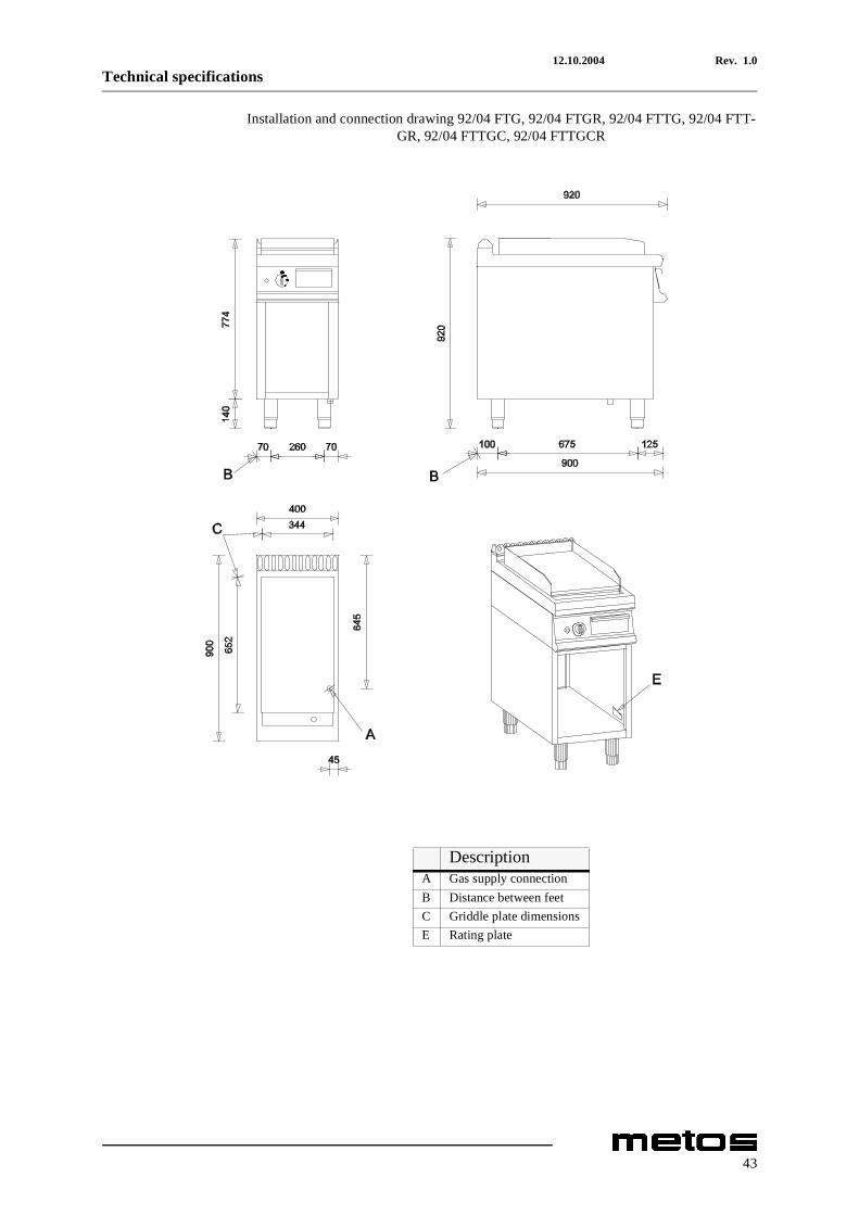
Installation and connection drawing 92/04 FTG, 92/04 FTGR, 92/04 FTTG, 92/04 FTT-GR, 92/04 FTTGC, 92/04 FTTGCR
DescriptionA Gas supply connectionB Distance between feetC Griddle plate dimensionsE Rating plate
43

12.10.2004 Rev. 1.0Technical specifications
Installation and connection drawing 94/04FTG, 94/04FTG1/2R, 94/04FTGR, 94/04FTTG, 94/04FTTG1/2R, 94/04FTTGR, 94/04FTTGC, 94/04FTTGC1/2R, 94/
04FTTGCR
DescriptionA Gas supply connectionB Distance between feetC Griddle plate dimensionsE Rating plate
44

12.10.2004 Rev. 1.0Technical specifications
Installation and connection drawing 94/04TFTG, 94/04TFTG1/2R, 94/04TFTGR, 94/04TFTTG, 94/04TFTTG1/2R, 94/04TFTTGR, 94/04TFTTGC, 94/04TFTTGC1/2R, 94/
04TFTTGCR
DescriptionA Gas supply connectionB Distance between feetC Griddle plate dimensionsE Rating plate
45

12.10.2004 Rev. 1.0Technical specifications
th
Item Model Type SpecificationVolume with package 92,92R,92T,92TR,92TC,92CR, 0,54 m³Volume with package 92TOP,92TOPR,92TOPT,92TOPC,92TOPCR 0,26 m³Volume with package 94,941/2R,94R,94T,94T1/2R,94TR,94TC,94TC1/2R,94TCR 1,02 m³Volume with package 94TOP,94TOP1/2R,94TOPR,94TOPT,94TOPT1/
2R,94TOPTR,94TOPTC,94TOPTC1/2R,94TOPTCR0,48 m³
Total weight 92,92R,92T,92TR,92TC,92CR, 90 kgTotal weight 92TOP,92TOPR,92TOPT,92TOPC,92TOPCR 66 kgTotal weight 94,941/2R,94R,94T,94T1/2R,94TR,94TC,94TC1/2R,94TCR 155 kgTotal weight 94TOP,94TOP1/2R,94TOPR,94TOPT,94TOPT1/
2R,94TOPTR,94TOPTC,94TOPTC1/2R,94TOPTCR125 kg
Plate dimensions 92,92R,92T,92TR,92TC,92CR,92TOP,92TOPR,92TOPT,92TOPC,92TOPCR
344 x 652 mm
Plate dimensions 94,941/2R,94R,94T,94T1/2R,94TR,94TC,94TC1/2R,94TCR,94TOP,94TOP1/2R,94TOPR,94TOPT,94TOPT1/2R,94TOPTR,94TOPTC,94TOPTC1/2R,94TOPTCR
744 x 652 mm
Griddle plate area 92,92R,92T,92TR,92TC,92CR,92TOP,92TOPR,92TOPT,92TOPC,92TOPCR
0,22 mm²
Griddle plate area 94,941/2R,94R,94T,94T1/2R,94TR,94TC,94TC1/2R,94TCR,94TOP,94TOP1/2R,94TOPR,94TOPT,94TOPT1/2R,94TOPTR,94TOPTC,94TOPTC1/2R,94TOPTCR
0,48 mm²
Griddle plate type 92,92TOP,92T,92TOPT,94,94TOP,94T,94TOPT Iron, smoothGriddle plate type 92R,92TOPR,92TOPTR,92TR,94R,94TOPR,94TOPTR,94TR Iron, ribbedGriddle plate type VAL 92TC,92TOPC,94TC,94TOPC Chromium, smooGriddle plate type 941/2R,94TOP1/2R,94T1/2R,94TOPT1/2R Iron, 1/2-ribbedRated output 92,92R,92T,92TR,92TC,92CR,92TOP,92TOPR,92TOPT,92TOP
C,92TOPCR8 kW
Rated output 94,941/2R,94R,94T,94T1/2R,94TR,94TC,94TC1/2R,94TCR,94TOP,94TOP1/2R,94TOPR,94TOPT,94TOPT1/2R,94TOPTR,94TOPTC,94TOPTC1/2R,94TOPTCR
16 kW
Air requirement for combustion 92,92R,92T,92TR,92TC,92CR,92TOP,92TOPR,92TOPT,92TOPC,92TOPCR
16 m3/h
Air requirement for combustion 94,941/2R,94R,94T,94T1/2R,94TR,94TC,94TC1/2R,94TCR,94TOP,94TOP1/2R,94TOPR,94TOPT,94TOPT1/2R,94TOPTR,94TOPTC,94TOPTC1/2R,94TOPTCR
32 m3/h
Construction type (IT) 92,92R,92T,92TR,92TC,92CR,92TOP,92TOPR,92TOPT,92TOPC,92TOPCR
A
Construction type (IT) 94,941/2R,94R,94T,94T1/2R,94TR,94TC,94TC1/2R,94TCR,94TOP,94TOP1/2R,94TOPR,94TOPT,94TOPT1/2R,94TOPTR,94TOPTC,94TOPTC1/2R,94TOPTCR
B11
Construction type (DE) 92,92R,92T,92TR,92TC,92CR,92TOP,92TOPR,92TOPT,92TOPC,92TOPCR
A
Construction type (DE) 94,941/2R,94R,94T,94T1/2R,94TR,94TC,94TC1/2R,94TCR,94TOP,94TOP1/2R,94TOPR,94TOPT,94TOPT1/2R,94TOPTR,94TOPTC,94TOPTC1/2R,94TOPTCR
B11
Gas inlet 3/4" GC ISO R7
46

DICHIARAZIONE DI CONFORMITÀ CE CE CONFORMITY DECLARATION
DECLARATION DE CONFORMITE CE
CE KONFORMITÄTSERKLÄRUNG
DECLARACIÓN DE CONFORMIDAD CE
OLIS S.p.A.
IMPIANTI PER LA RISTORAZIONE
32030 BRIBANO - Belluno - Italy
Via Cavalieri di Vittorio Veneto,14
Telefono +39-437-8558 (5 linee r.a.)
Fax +39-0437- 838274
http://www.olis.it e-mail:[email protected]
Cap. Soc. € 2.500.000.
Registro delle Imprese 00917220256 R.E.A. n. 82605
Codice Fiscale e Partita IVA IT 009177220253
Si dichiara che il seguente apparecchio: Fry top gas serie 900 INNO
We declare that the following equipment: Gas Fry tops series 900 INNO
Nous déclarons que l'appareil suivont: Plaque grillade gaz gamme 900 INNO
Wir erklären, dass dieses Gerät: Gas-Grillplatten serie 900 INNO
Se declara que el siguiente aparato: Fry-top a gas gama 900 INNO
Mod.: 92/04FTG, 92/04FTGR, 94/04FTG, 94/04FTG1/2R, 94/04FTGR, 92/04TFTG,
92/04TFTGR, 94/04TFTG, 94/04TFTG1/2R, 94/04TFTGR, 92/04FTTG, 92/04FTTGR,
92/04FTTGC, 92/04FTTGCR, 94/04FTTG, 94/04FTTG1/2R, 94/04FTTGR, 94/04FTTGC,
94/04FTTGC1/2R, 94/04FTTGCR, 92/04TFTTG, 92/04TFTTGR, 92/04TFTTGC,
92/04TFTTGCR, 94/04TFTTG, 94/04TFTTG1/2R, 94/04TFTTGR, 94/04TFTTGC,
94/04TFTTGC1/2R, 94/04TFTTGCR
è conforme alla direttiva 90/396 CEE
is in specification with the directive 90/396 CEE
est conforme aux directives 90/396 CEE
entspricht die 90/396 CEE Richtlinie
esta conforme las directrices 90/396 CEE
Certificato CE IMQ Nr. 51BP2616 del 21-04-2004
IMQ CE certificate Nr. 51BP2616 on 21-04-2004
Certificat CE IMQ Nr. 51BP2616 du 21-04-2004
IMQ CE Certificat Nr. 51BP2616 vom 21-04-2004
Certificado CE IMQ Nr. 51BP2616 con fecha 21-04-2004
Bribano, 21/04/2004 OLIS S.p.A.
Amministratore Delegato
P. Candiago