GAMBREL ROOF ARCHES FOR FARM AND STORAGE BUILDINGS · GAMBREL ROOF ARCHES FOR FARM AND ... H.A. and...
5
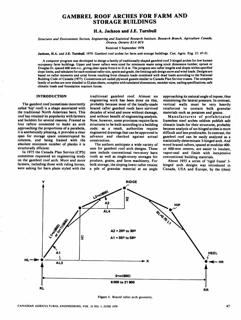
GAMBREL ROOF ARCHES FOR FARM AND STORAGE BUILDINGS H.A. Jackson and J.E. Turnbull Structures and Environment Section, Engineering and Statistical Research Institute, Research Branch, Agriculture Canada, Ottawa, Ontario KIA 0C6 Received 5 September 1978 Jackson, H.A. and J.E. Turnbull. 1979. Gambrel roof arches for farm and storage buildings. Can. Agric. Eng. 21: 47-51. A computer program was developed to design a family of traditionally shaped gambrel roof 3-hinged arches for low human occupancy farm buildings. Upper and lower rafters were sized for minimum waste using stock dimension lumber, spruce or Douglas fir, spaced 600 mm o.c, giving clear spans from 6 to 21.6 m. The program sets rafter lengths and slopes within specified slope limits, and tabulates for each nominal rafter size, specie and grade, the limiting safe design snow and wind loads. Designs are based on rafter moments and axial forces resulting from climatic loads combined with dead loads according to the National Building Code of Canada (1977). Connections are nailed plywood gussets similar to Canada Plan Service trusses. The complete family of arches are now detailed in 52 plan sheets, complete with tabulated dimensions, member sizes, nailing specifications, safe climatic loads and foundation reaction forces. INTRODUCTION The gambrel roof (sometimes incorrectly called 'hip' roof) is a shape associated with the traditional North American barn. This roof has retained its popularity with farmers and builders for several reasons. Framed as four rafters connected to make an arch approaching the proportions of a parabola, it is aesthetically pleasing, it provides a clear span for storage space uninterrupted by columns, and being framed with the absolute minimum number of planks it is structurally efficient. In 1975 the Canada Plan Service (CPS) committee requested an engineering study on the gambrel roof arch. More and more farmers, including those with riding horses, were asking for barn plans styled with the HL- traditional gambrel roof. Almost no engineering work has been done on this, probably because most of the locally-made braced rafter gambrel roofs have survived decades of wind and snow without damage, and without benefit of engineering analysis. Now, however, some provinces require farm structures to be built according to a building code; as a result, authorities require engineered drawings that can be approved in advance and checked against actual construction. The authors anticipate a wide variety of uses for gambrel roof arch designs. These uses include conventional two-story barn roofs as well as single-storey storages for produce, grains, and farm machinery. For bulk storage, the sloping lower rafter retains a pile of granular material at an angle Figure 1. Braced rafter arch geometry. CANADIAN AGRICULTURAL ENGINEERING. VOL. 21 NO. I, JUNE 1979 approaching its natural angle of repose, thus minimizing the lateral pressure. In contrast, vertical walls must be very heavily reinforced to contain bulk granular materials such as potatoes and grains. Manufacturers of prefabricated frameless steel arches seldom publish safe climatic loads for their structures, probably because analysis of no-hinged arches is more difficult and less predictable. In contrast, the gambrel roof can be easily analyzed as a statistically-determinate 3-hinged arch. And wood braced rafters, spaced at modular 400- or 600-mm centers, are easier to insulate, vapor-seal and finish with inexpensive conventional building materials. About 1955 a series of 'rigid frame' 3- hinged arch designs was introduced in Canada, USA and Europe, by the (then) HEEL HR 47
Transcript of GAMBREL ROOF ARCHES FOR FARM AND STORAGE BUILDINGS · GAMBREL ROOF ARCHES FOR FARM AND ... H.A. and...
GAMBREL ROOF ARCHES FOR FARM ANDSTORAGE BUILDINGS
H.A. Jackson and J.E. Turnbull
Structures and Environment Section, Engineering andStatistical Research Institute, Research Branch, Agriculture Canada,Ottawa, Ontario KIA 0C6
Received 5 September 1978
Jackson, H.A. and J.E. Turnbull. 1979. Gambrel roof arches for farm and storage buildings. Can. Agric. Eng. 21: 47-51.
A computer program was developed to design a family of traditionally shaped gambrel roof 3-hinged arches for low humanoccupancy farm buildings. Upper and lower rafters were sized for minimum waste using stock dimension lumber, spruce orDouglas fir, spaced 600 mm o.c, giving clear spans from 6 to 21.6 m. The program sets rafter lengths and slopes within specifiedslope limits, and tabulates for each nominal rafter size,specieand grade, the limiting safe design snow and wind loads. Designsarebased on rafter moments and axial forces resulting from climatic loads combined with dead loads according to the NationalBuilding Code of Canada (1977). Connections are nailed plywood gussets similar to Canada Plan Service trusses. The completefamily of arches are now detailed in 52 plan sheets, complete with tabulated dimensions, member sizes, nailing specifications, safeclimatic loads and foundation reaction forces.
INTRODUCTION
The gambrel roof (sometimes incorrectlycalled 'hip' roof) is a shape associated withthe traditional North American barn. This
roof has retained its popularity with farmersand builders for several reasons. Framed asfour rafters connected to make an arch
approaching the proportions of a parabola,it is aesthetically pleasing, it provides a clearspan for storage space uninterrupted bycolumns, and being framed with theabsolute minimum number of planks it isstructurally efficient.
In 1975 the Canada Plan Service (CPS)committee requested an engineering studyon the gambrel roof arch. More and morefarmers, including those with riding horses,were asking for barn plans styled with the
HL-
traditional gambrel roof. Almost noengineering work has been done on this,probably because most of the locally-madebraced rafter gambrel roofs have surviveddecades of wind and snow without damage,and without benefit of engineering analysis.Now, however, some provinces require farmstructures to be built according to a buildingcode; as a result, authorities requireengineered drawings that can be approved inadvance and checked against actualconstruction.
The authors anticipate a wide variety ofuses for gambrel roof arch designs. Theseuses include conventional two-story barnroofs as well as single-storey storages forproduce, grains, and farm machinery. Forbulk storage, the sloping lower rafter retainsa pile of granular material at an angle
Figure 1. Braced rafter arch geometry.
CANADIAN AGRICULTURAL ENGINEERING. VOL. 21 NO. I, JUNE 1979
approaching its natural angle of repose, thusminimizing the lateral pressure. In contrast,vertical walls must be very heavilyreinforced to contain bulk granularmaterials such as potatoes and grains.
Manufacturers of prefabricatedframeless steel arches seldom publish safeclimatic loads for their structures, probablybecause analysis of no-hinged arches is moredifficult and less predictable. In contrast, thegambrel roof can be easily analyzed as astatistically-determinate 3-hinged arch. Andwood braced rafters, spaced at modular 400-or 600-mm centers, are easier to insulate,vapor-seal and finish with inexpensiveconventional building materials.
About 1955 a series of 'rigid frame' 3-hinged arch designs was introduced inCanada, USA and Europe, by the (then)
HEEL
HR
47
CaseS
+0.01 W fori
W,kN/m2
Windwardside
Case 4
* reduce to 0.6 for roofs exposed to wind.
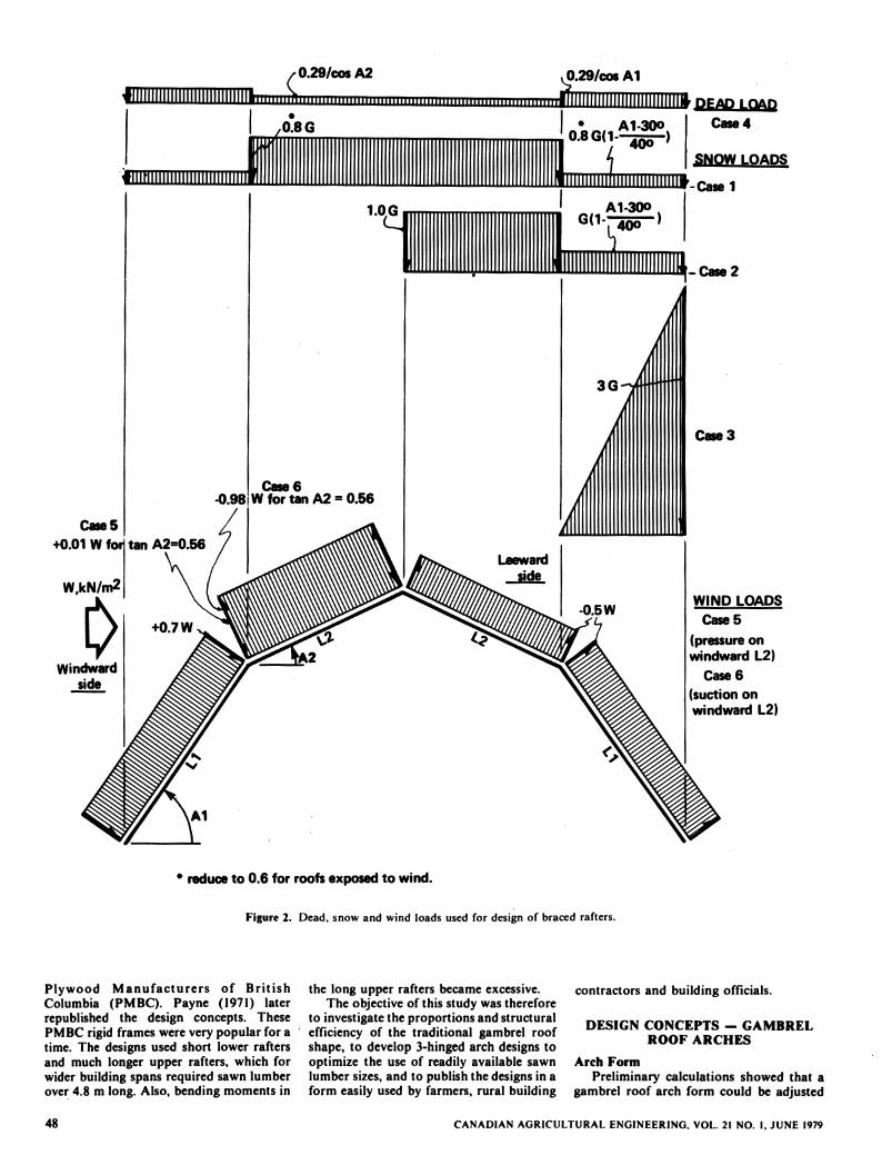
Figure 2. Dead, snow and wind loads used for design of braced rafters.
Plywood Manufacturers of BritishColumbia (PMBC). Payne (1971) laterrepublished the design concepts. ThesePMBC rigid frames were very popular for atime. The designs used short lower raftersand much longer upper rafters, which forwider building spans required sawn lumberover 4.8 m long. Also, bending moments in
48
the long upper rafters became excessive.The objective of this study was therefore
to investigate the proportions and structuralefficiency of the traditional gambrel roofshape, to develop 3-hinged arch designs tooptimize the use of readily available sawnlumber sizes, and to publish the designs in aform easily used by farmers, rural building
contractors and building officials.
DESIGN CONCEPTS - GAMBRELROOF ARCHES
Arch Form
Preliminary calculations showed that agambrel roof arch form could be adjusted
CANADIAN AGRICULTURAL ENGINEERING. VOL. 21 NO. I, JUNE 1979
within broad limits to safely maximizeuseful storage volume while minimizingbuilding material costs. This optimizationyielded the arch form shown in Fig. 1, withlower rafter angles Al set between 55° and60°, and upper rafter angles A2 between 20°and 30°. To ensure the use of stock lumberlengths for minimum cutting waste, all rafterlengths were set in multiples of 600 mm.Rafter lengths were either all equal (LI =L2), or the lower rafters (LI) were 600 mmlonger than the upper ones (L2). The lengthsof hip joint brace members (BL) were set at0.75 times the lower rafter length LI,truncated down to the nearest whole 300-
mm length, and located symmetrically aboutthe hip joint. All joints (heel, hip, ridge andbrace ends) were considered as hinged,making the arch statically determinate, andno adjustments were made to allow forpossible stiffness or strength increases due tothe semi-rigid nailed connections actuallyused.
Design LoadsInternal storage loads were not
considered, but external climatic loads weretaken mostly from the National BuildingCode of Canada (1977), as detailed inSupplement No. 4. As usual for farmbuildings, earthquake loads were notconsidered. Snow loads were considered asillustrated in Fig. 2, cases 1, 2 and 3; eachsnow load was added to dead load, case 4.Dead load was assumed at 0.29 kN/m2 ofroof surface, considered in the plane of theroof; this was divided by the cosines of roofangles A1 and A2 respectively, to convert toroof surface horizontally projected. Snowload cases 1 and 2 were taken directly fromthe Code (1977); case 3 was developed tocheck for the single-storey situation wherethe arch heel is supported very close tograde. In this case, a combination of driftsnow and snow sliding off the upper rafterscan pile against the lower rafter LI. Taylor(Personal communication; D.A. Taylor,Structures Section, Div. of Bldg. Res., Nat.Res. Council, Montreal Road, Ottawa, Ont.K1A 0R6) was consulted for the distributionand magnitude of that portion of the snowpile estimated to be supported by the roof(up to 3 G in this case).
Wind loads were based partly on theNational Building Code of Canada (1977)which does not give pressure coefficientsspecifically for gambrel roofs, and partly onFenton and Otis (1941). For the lowerwindward rafter, a pressure coefficient of +0.7 was taken from Fenton and Otis (1941);for the upper windward rafter, the Codesuggests checking a range from positivethrough negative pressures, as shown in Fig.2, cases 5 and 6. For the leeward roofslopes,-0.5 is given by both references. For eacharch form and rafter size selected, pressurecoefficients were used to determinemaximum allowable wind pressures. Thesepressures in turn were related to themaximum 1-hwind speed having one chancein 10 of being exceeded in any given year,
multiplied by 2.0 (gust factor) and 1.0(exposure factor).
Connections and Sawn Lumber
It was decided to use the same type ofconnections as in the CPS trusses; that is, 12-mm Douglas fir plywood gussets nailed toboth sides of 38-mm spruce or Douglas firframe members. Special 5 x 64-mm (6 gageX 2'/i inch) 'Truss Gusset* nails are notalways available (or suppliers won't botherto order them), so 4 x 64-mm specialconcrete nails were substituted. Like the
Truss Gusset* nails formerly specified, thesedevelop two shear planes (double shear) byfully penetrating two plywood gussets whennailed from both sides of the joint. Based onTurnbull and Theakston (1964) basic doubleshear nail loads of 778 and 970 N/nail forspruce and Douglas fir respectively wereused, modified by the 1.25 iow humanoccupancy* factor allowed by the CanadianFarm Building Code (1977) as well as 'loadduration* factors appropriate to the climaticloads considered (1.15 for snow, 1.33 forwind) as listed in CSA Standard 086 (1976).'Dry* service conditions were assumed(factor 1.00); whenever arches could beexposed to 'wet* service such as inuninsulated winter animal housing, it issuggested that safe climatic loadsdetermined for a given arch design should bereduced by a 0.75 multiplying factor. Thisfactor was set between the 0.84 factor forwood members in bending and the 0.69 forcompression parallel to grain, asrecommended by CSA 086 (1976). This isbecause braced rafters are typically stressedby bending and axial compressioncombined.
PROGRAM METHODOLOGY
The major computer program steps arelisted as follows:1. Input rafter size, rafter span, low or
high human occupancy, rafter spacing,lumber grade and type.
2. Calculate rafter lengths, slopes andbrace length.
3. Determine snow, wind and dead loadcoefficients based on rafter slopes.
4. Calculate reactions, moments, axialand shear forces due to unit snow, unitwind and dead loads.
5. Determine allowable compressionstress in rafter.
6. Determine location of criticalcombined axial and bending stress, forload cases 1, 2, 3, 5 or 6, each added todead load 4.
7. Determine maximum allowable groundsnow load G for cases 1, 2 or 3, each.added to 4.
8. Determine maximum allowable 1/10hourly wind load for cases 5 or 6, eachadded to 4.
9. Check maximum allowable 1/10hourly wind load when combined withmaximum allowable ground snow plusdead load (from step 7).
10. Check maximum allowable ground
CANADIAN AGRICULTURAL ENGINEERING, VOL. 21 NO. I, JUNE 1979
snow load when combined withmaximum 1/10 hourly wind plus deadload (from step 8).
11. Determine critical force at ridge, brace,hip and heel.
12. Determine number of nails at ridge,brace and hip gussets.
13. Check compression stresses in 38 x 89-mm brace.
14. Print results.
The assumptions for steps 2, 3 and 12above have already been explained. In step 4the moment, axial and shear forces werecalculated at 25-mm horizontal increments
across the span of the arch for each loadcase. The axial force in the brace on each
side is calculated for each load case.
In step 5, the program assumes that allrafters are laterally supported in thethickness dimension by roof purlins in orderto qualify as 'short columns* for assigningallowable compression stresses. Theprogram checks the slenderness ratio in thedepth direction and modifies the allowablecompressive stress for this if necessary. Endfixity factor k = 0.65 was assumed.
In step 6, the trial and error method isused to find the location of the criticalcombined stress.
In steps 7, 8, 9 and 10, trial and erroriterations are used to determine the loads.
In step 13, the program checks theslenderness ratio of the brace in both thethickness and depth directions of themember (assumed k - 0.65) as before. Indepth, the compressive stress is reduced ifnecessary; in thickness, lateral bracingand/or compressive stress reduction areapplied.
RESULTS AND DISCUSSION
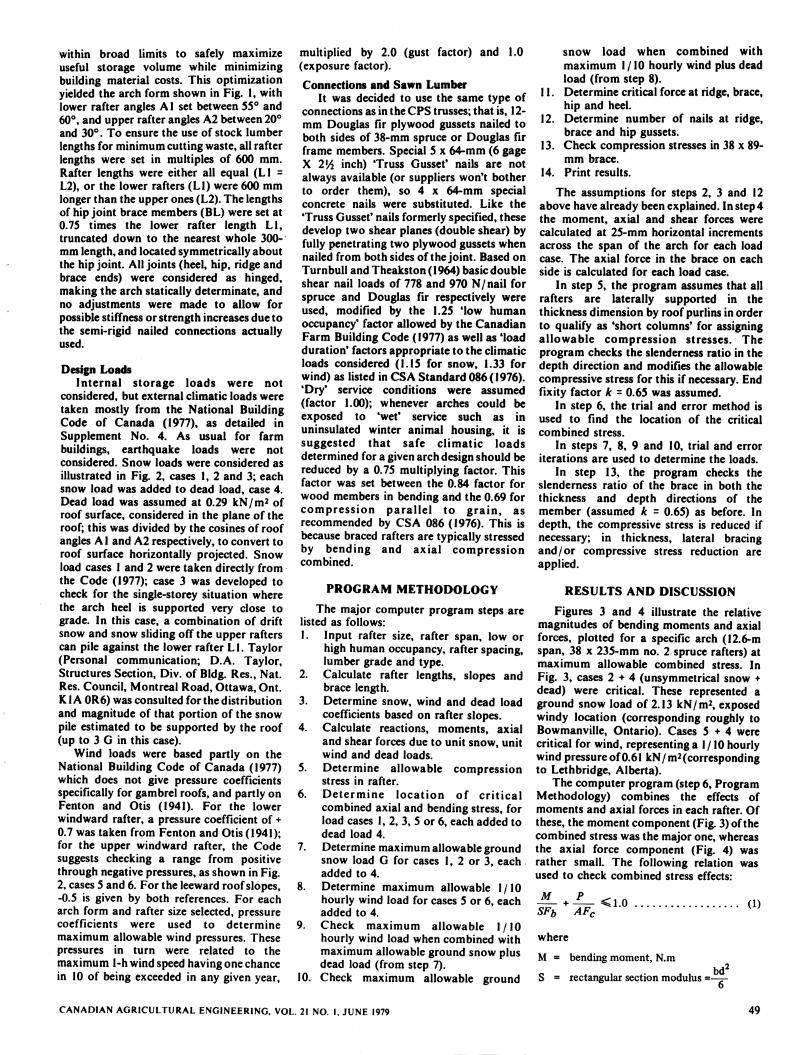
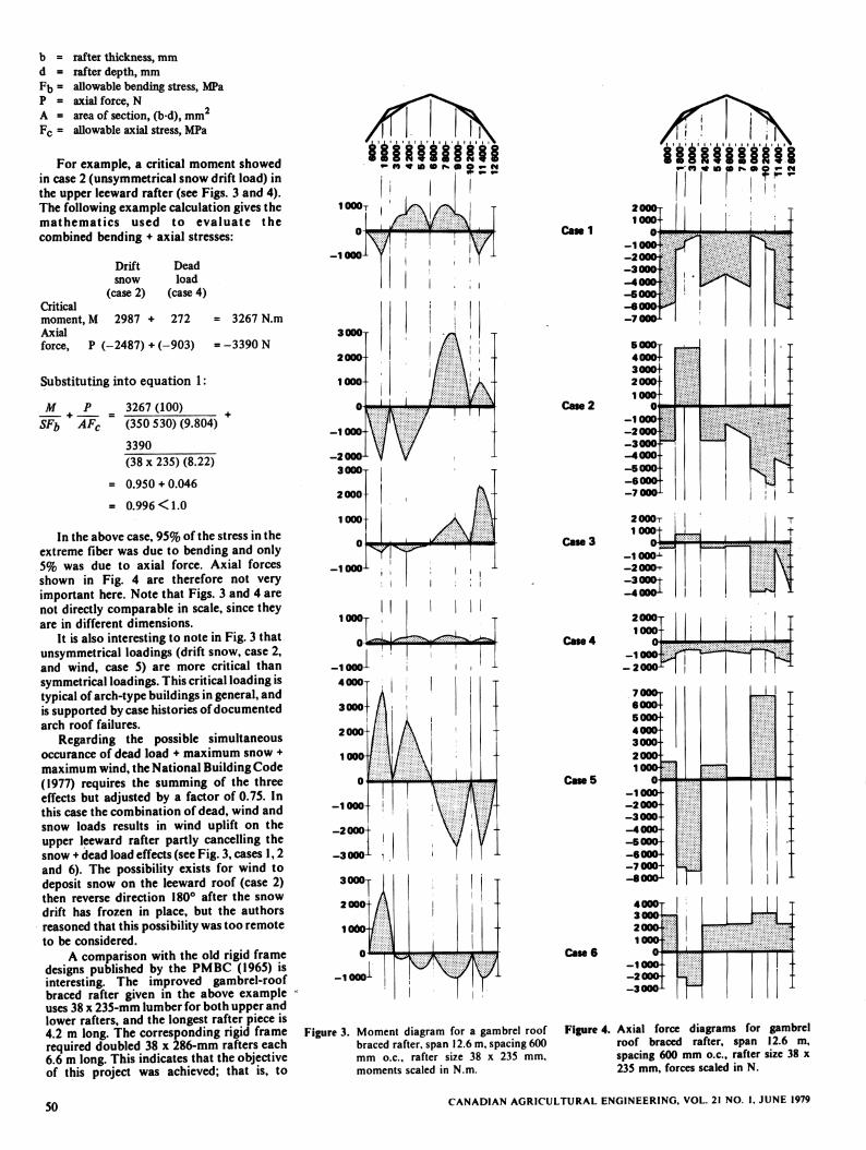
Figures 3 and 4 illustrate the relativemagnitudes of bending moments and axialforces, plotted for a specific arch (12.6-mspan, 38 x 235-mm no. 2 spruce rafters) atmaximum allowable combined stress. InFig. 3, cases 2 + 4 (unsymmetrical snow +dead) were critical. These represented aground snow load of 2.13 kN/m2, exposedwindy location (corresponding roughly toBowmanville, Ontario). Cases 5+4 werecritical for wind, representing a 1/10 hourlywind pressure of 0.61 kN/m2(correspondingto Lethbridge, Alberta).
The computer program (step 6, ProgramMethodology) combines the effects ofmoments and axial forces in each rafter. Ofthese, the moment component (Fig. 3) of thecombined stress was the major one, whereasthe axial force component (Fig. 4) wasrather small. The following relation wasused to check combined stress effects:
M
SFb AFr<1.0
where
M = bending moment, N.m
S = rectangular section modulus =
(1)
bd'
49
b • rafter thickness, mmd = rafter depth, mmF0 = allowable bending stress, MPaP = axial force, NA = area of section, (b-d), mmFc = allowable axial stress, MPa
For example, a critical moment showedin case 2 (unsymmetrical snow drift load) inthe upper leeward rafter (see Figs. 3 and 4).The following example calculation gives themathematics used to evaluate the
combined bending + axial stresses:
Drift Dead
snow load
(case 2) (case 4)Critical
moment, M 2987 + 272 3267 N.m
Axialforce, P (-2487) + (-903) = -3390 N
Substituting into equation 1:
JL +J__ 3267 (100) +SFb +AFC = (350 530) (9.804)
3390(38 x 235) (8.22)
= 0.950 + 0.046
= 0.996 < 1.0
In the above case, 95% of the stress in theextreme fiber was due to bending and only5% was due to axial force. Axial forcesshown in Fig. 4 are therefore not veryimportant here. Note that Figs. 3 and 4 arenot directly comparable in scale, since theyare in different dimensions.
It is also interesting to note in Fig. 3 thatunsymmetrical loadings (drift snow, case 2,and wind, case 5) are more critical thansymmetrical loadings. This critical loadingistypical of arch-typebuildingsin general, andis supportedby casehistoriesof documentedarch roof failures.
Regarding the possible simultaneousoccurance of dead load ♦ maximum snow +maximum wind, the National Building Code(1977) requires the summing of the threeeffects but adjusted by a factor of 0.75. Inthis case the combination of dead, wind andsnow loads results in wind uplift on theupper leeward rafter partly cancelling thesnow +dead load effects (see Fig. 3, cases 1,2and 6). The possibility exists for wind todeposit snow on the leeward roof (case 2)then reverse direction 180° after the snowdrift has frozen in place, but the authorsreasoned that this possibility was too remoteto be considered.
A comparison with the old rigid framedesigns published by the PMBC (1965) isinteresting. The improved gambrel-roofbraced rafter given in the above exampleuses 38 x 235-mm lumber for both upper andlower rafters, and the longest rafter piece is4.2 m long. The corresponding rigid framerequired doubled 38 x 286-mm rafters each6.6 m long. This indicates that the objectiveof this project was achieved; that is, to
50
llWftlWl
Catel
Case 2
Case 3
Case 4
Case 5
i I
Case 6
il'i'iWi'i'fti•- « * to co rv o» p «- w
-3
-7
2000t
1000+
ipi
rr4000t
ii
| ••'• Lj200o|30001 T-
••
Figure 3. Moment diagram for a gambrel roof Figure 4. Axial force diagrams for gambrelbraced rafter, span 12.6 m,spacing 600 roof braced rafter, span 12.6 m,mm o.c, rafter size 38 x 235 mm, spacing 600 mm o.c, rafter size 38 xmoments scaled in N.m. 235 mm, forces scaled in N.
CANADIAN AGRICULTURAL ENGINEERING, VOL. 21 NO. I. JUNE 1979
improve the structural efficiency of woodarches.
SUMMARY
The Canada Plan Service has written^
engineered result"^Xl olderfiCh a«nmeSlywth^ smaller lumberdesigns, especially £«n These designssizes now available in^"""g Build ng
andCfonneections are b««d^l^tio«UCanada Plan Service method, using large,
CPS trusses.
ASSOCIATE COMMITTEE 1977 NaUon-Building Code of Canada. NRCC No !5»5.National Research Council of Canada,
ASS°0CuV?nC0MM.TTEE. .977 CommenVaries on part 4of the National Bujdmg Code
nf Canada Supplement No. 4. NRCC no.°5558.Clonal Research Council of Canada,caSadTan^tandards association.
1976 Code for the engineering des.gn of wood
«MDMN.owmrt;(M1 nwrnamnwVOL»"O.UVHE,979
CSA Standard 086, Can. Stand. Assoc, 178Rexdale Blvd., Rexdale, Ontario. CanFENTON Vc. and C.K. OT1* 1941 TheResignof barns to withstand wind loads. BuU.42,Eng. Exp. Sta., Kansas State College,November P.VWOod construction
PAYNE, "-J- 'J'-cSl of the Fores.SSS-2- Bntisrfcolumbi, Vancouver.PLYWOOD MANUFACTURERS OF
BRITISH COLUMBIA. 1965. F.r plywoodfigid fame selection manual. Councl of theForest Industries of British Columbia (CF1).,055 W. Hastings St Vancouver B.C
TURNBULL JE. and F.H. THtAKSiy"-TUX iUsi. of Plywood gusset connectionswith steel nails. E1C - 64 - BR and STR 3DW paper of the Eng. Inst, of Canada. Vol. 2,No. 2, March.
51