GA ATMOS Scopecdn.atmosmed.com/docs/1184/gb_ga_scope_2016-01_vers16.pdf · Name: ATMOS® Scope /...
36
Operating instructions English ATMOS ® Scope ATMOS ® Scope Basic REF 950.0300.B REF 950.0330.B TPA191-158-1112-01_L 2016-01 Index: 18
Transcript of GA ATMOS Scopecdn.atmosmed.com/docs/1184/gb_ga_scope_2016-01_vers16.pdf · Name: ATMOS® Scope /...

Ope
ratin
g in
stru
ctio
ns
English
ATMOS® ScopeATMOS® Scope Basic
REF 950.0300.BREF 950.0330.BTPA191-158-1112-01_L2016-01 Index: 18

2
Table of contents
Further information, accessories, consumables andspare parts are available from:
ATMOSMedizinTechnik GmbH & Co. KGLudwig-Kegel-Straße 1679853 LenzkirchGermany
Tel +49 7653 689-0Fax +49 7653 689-190 +49 7653 689-292 (Service Center)
1.0 Introduction .................................................................. 31.1 Notes on operating instructions ...................................... 31.2 Intended Use .................................................................. 41.3 Function ......................................................................... 41.4 Explanation of pictures and symbols .............................. 51.5 Scope of supply ............................................................. 5
2.0 For your safety ............................................................. 62.1 Instructions for combination with other Medical Products .................................................. 6 3.0 Setting up and starting up ........................................... 73.1 Overview ....................................................................... 73.2 Front view ATMOS® Scope controller ............................. 83.3 Rear view ATMOS® Scope controller ............................. 83.4 Overview Cables ............................................................ 93.5 Leakage tester and hose ................................................ 93.6 Assembly/First Installation ........................................... 103.7 Tests ............................................................................. 16
4.0 Operation .................................................................... 184.1 Use/Operation .............................................................. 184.2 Disassembly ................................................................. 20 4.3 Functions of the buttons on the handle ........................ 20
5.0 Cleaning ...................................................................... 215.1 General Instructions ..................................................... 215.2 Manual Cleaning and Disinfection ................................ 225.3 Mechanical Processing and Disinfection ...................... 245.4 Sterilization ................................................................... 255.4.1 General Instructions ..................................................... 255.4.2 Sterilization Methods .................................................... 25
6.0 Maintenance and service ........................................... 27
7.0 Trouble shooting ........................................................ 28 8.0 Accessories and Spare parts .................................... 29
9.0 Technical specifications ............................................ 31
10.0 Disposal ...................................................................... 32
11.0 Notes on EMC ............................................................. 33

3
1.0 Introduction
1.1 Notes on operating instructions
These operating instructions contain important notes on how to operate the ATMOS® Scope safely, correctly and effectively. Their reading helps to avoid risks, and also to reduce repair costs and down-time. That increases, amongst other things, the reliability and service-life of the device.These operating instructions serve not only for new operating personnel to be instructed in its use, but also for use as a reference manual. Reprints (also in extracts) only with permission in written form by ATMOS.These operating instructions must always be kept available near the device.
Care and safety inspections in conjunction with professional execution provide for operational safety and readiness for use of your ATMOS® Scope and are therefore a must besides regular cleaning. Repair work and safety inspections may only be carried out by expert personnel authorised by ATMOS. By applying only original spare parts you will have the guarantee that operational safety, readiness for work and the value of your ATMOS® Scope will be preserved.
● The product ATMOS® Scope bears CE marking CE according to the EU guideline of the council for medical products 93/42/EEC and meets the basic requirements of annex I of this guideline.● The product ATMOS® Scope complies with all applicable requirements of the directive 2011/65/EC restricting the use of certain hazardous substances in electrical and electronic equipment (“RoHS”).● The declaration of conformity and our standard general terms and conditions can be obtained on our website at www.atmosmed.com.● The quality management system applied at ATMOS has been certified according to international standards EN ISO 9001 and EN ISO 13485.● Prior to start-up please peruse chapter 2.0 „For your safety“, in order to be prepared for any possible dangerous situations.
● These operating instructions are valid for the following devices: ATMOS® Scope ...............................REF 950.0300.0 ATMOS® Scope Basic .....................REF 950.0330.0

4
1.0 Introduction
1.2 Intended UseName: ATMOS® Scope / ATMOS® Scope Basic
Main functions: During an endoscopy procedure the use of the ATMOS® Scope / ATMOS® Scope Basic is indicated for the temporary application in the mouth cavity up to the throat and in the nasal cavity. It enables the visualization of body orifi ces and body cavities.
Med. indications/ application: For the endoscopic visualisation and diagnosis in the mouth and the nasal cavities and in the upper airway anatomy and in the auditory canal with the eardrums.
Specifi cation of the main function: With the all-in-one handle solutions and with the innovative chip-on-tip technology, the integrated camera and integrated LED lightsource makes endoscopy and stroboscopy possible: - Bright homogenous illumination - 1/18” CMOS image sensor with a high resolution of 328 x 250 - Optical angle 85° - Distal outer diameter 3.8 mm - Working length 300mm - Angulation angle 2 x 160° - 100% waterproof
Application organ: Nasal and oral cavities to the larynx, auditory canal to the ear drums
Application time: Temporarily
Application site: In clinics and practices for ENT doctors and phoniatricians.
Contraindications: The use of CMOS-Video-Nasopharyngoscope is contraindicated if endoscopic applications are contraindicated for any reason.
The product is: Active
Sterility: Not sterile
Single use product / reprocessing: Reprocessing is possible
1.3 Function
The ATMOS® Scope/ATMOS® Scope Basic is an all-in-one solution for the fl exible endoscopy. The fl exible naso-pharyngoscope with integrated camera and LED light source combines the following components in the handle:
LED light source Microphone pre-amplifi er and removable microphone (optional) camera electronics mechanics for controlling the angle
The innovatively-shaped handle of the ATMOS® Scope/ATMOS® Scope Basic embodies an entirely new way of performing endosco-py/stroboscopy, allowing insertion of the probe without any problem for the fatigue free examination of ear, nose, pharynx and larynx without any signs of fatigue.
Thanks to optimised video pre-settings, camera setting and white balance are no longer required. The device automatically switches to the desired stroboscopy mode.
The handle provides the following keys:
Start-stop for video recording Single images storage is possible in connection with the ATMOSoft ENT
The ATMOS® Scope/ATMOS® Scope Basic fi ts perfectly into the ATMOS® treatment units. Networking with the ATMOS® Cam, the ATMOS® Strobo 21 LED and a video monitor is always possible. Images and videos can be saved with the ATMOSoft ENT.

5
1.4 Explanation of pictures and symbols
1.0 Introduction
!
■
●
→
clickclick
Graphic symbols contained in the manual
Warning,special diligent notice!
Abbreviations / symbols contained in this manual
Important information
ATMOS® Scope symbols
Serial number
Order number
Creation date
The CE sign shows that this product meets the appropriate requirements of the EUguidelines.
REF
SN Observe operating instructions!
Dispose of properly
1.5 Scope of supply
The ATMOS® Scope was functionally tested and carefully packed prior to delivery. Immediately after receiving the delivery check for completeness (see delivery note).
ATMOS® Scope Basic: ATMOS® Scope handle, controller, leakage tester, pressure compensation cap, BNC video cable (2 pcs), silicone hose, mains cable, BNC chinch adapter (2 pcs), USB 2.0 cable, remote cable for ATMOSoft, ATMOSoft demo CD, operating instructions.
ATMOS® Scope: ATMOS® Scope handle, controller, leakage tester, pressure compensation cap, microphone, stroboscope cable, BNC video cable (2 pcs), silicone hose, mains cable, BNC chinch adapter (2 pcs), USB 2.0 cable, remote cable for ATMOSoft, ATMOSoft demo CD, transport case, operating instructions.
Please press where dot indicates
Follow the arrows whilst proceeding, sequence
Please read, important information
Subnumeration
Numeration
General information
CheckReplace
Move, plug ... in this direction
Engage, check correct fi t
Turn, shift ... in this direction
Application part type BF acc. to EN 60601-1
Manufacturer
+158°F+70°C
+68°F-20°C
ROnly
LatexIndicates the tolerable temperature
The federal law of the USA restricts the sale of this device to physicians or orders on their behalf
Indication that the product does not contain natural rubber latex
95%
5%
106 kPa
70kPa
Indicates the tolerable air humidity
Indicates the tolerable air pressure
Magnetic resonance unsafe
Fuse
Sterilize prior to each useNONSTERILE
MR
!2nd-Edition IEC 60601-1: Caution, observe accompanying documents3rd-Edition IEC 60601-1: Caution

6
2.0 For your safety
!For your safety
The product may only be used observing the guidelines of this IFU. If instructions, warnings and precautions are not observed, this may lead to risks and serious consequences during use. Check and guarantee unrestricted function, completeness and integrity of the product and/or accessories before use.
The system may only be operated with the delivered cables. Make sure that all devices operated nearby comply with the relevant EMC requirements. The image quality could be affected by the electromagnetic emissions of peripheral equipment (e. g. monitor, video equipment) which is connected. In case of extreme electromagnetic interferences, the image quality may be infl uenced (e. g. slight stripes, color changes on the monitor).
Use in combination with MR The product is MR unsafe - in areas with magnetic resonance imaging, the product is unsafe
To separate the device completely from the mains power supply, pull the plug out of the mains socket at the external power.
The plug cap must be removed from the plug during storage and transport. Otherwise, under certain circumstances, an overpressure could occur within the connection cable and could damage the cable.
When placing the product into the transport case, be careful that no parts are pinched or clamped when closing the lid. Otherwise the product could be damaged.
Do not use the transport case for long-time storage.
Accessories and/or peripheral devices, which are connected to the interfaces of the product must comply verifi ably to the relevant normative specifi cations (e. g. IEC 60601-1). Furthermore, all confi gurations of the system standard IEC 60601-1-1 have to be fulfi lled.
Unsterile parts – danger of infection Parts, which are delivered unsterile, have to be processed before use.
Improper use and maintenance, as well as application in deviance to its intended use may lead to risks for patient and user or early wear and tear of the product.
Endoscopic procedures may only be carried out by specialists who have corresponding training, knowledge and experience.
The product is susceptible in regard to bending, heavy kinking, torsion, tension or pressure load. This may damage the optical components and thus lead to operating failure.
Only operate the product within the specifi ed operating temperature range.
Image interferences, image breakdown or breakdown of the integrated light source could lead to risks.
In this case, release defl ection lever and carefully withdraw the videoscope.
Do not look directly into the light emission at the distal end of the endoscope. This can lead to eye injury.
Each light source can become warm due to absorption and therefore damage to the biological tissue could occure. Please make sure to keep the application period as short as necessary, to switch off the light source when not in use and if need be to check the heat generation prior to application.
The ATMOS® Scope may only be operated in rooms used for medical purposes, but not in areas subject to explosion hazards and in oxygen rich environments.
2.1 Instructions for combination with other medical products
Multiplication of leakage current - risk for patients If the product is used with electro medical devices and/or
power driven endoscopic accessories, the leakage cur-rents could multiplicate. Check external electrical devices before use.
If the product or endoscopic accessories are used with products of different manufacturers and in combination with medical electrical products, ensure that the BF con-ditions (insulated, earth-free application part) are fulfi lled.
Ensure that the corresponding interconnection c#onditions are kept. Also, the relevant standard and the respective national tolerances must be followed.
7
3.0 Setting up and starting up
3.1 Overview
Defl ection lever Plug
Pressure compensation valve with dust protection cap Plug cap
Microphone (optional) Defl ectable tip
Button A Tip cover glass
Button B Microphone interface
Connection cable
Fig. 1
1
23
45
6
78
910
11
1
2 3
4
5
6
7 8
10
9
11
3
8
3.0 Setting up and starting up
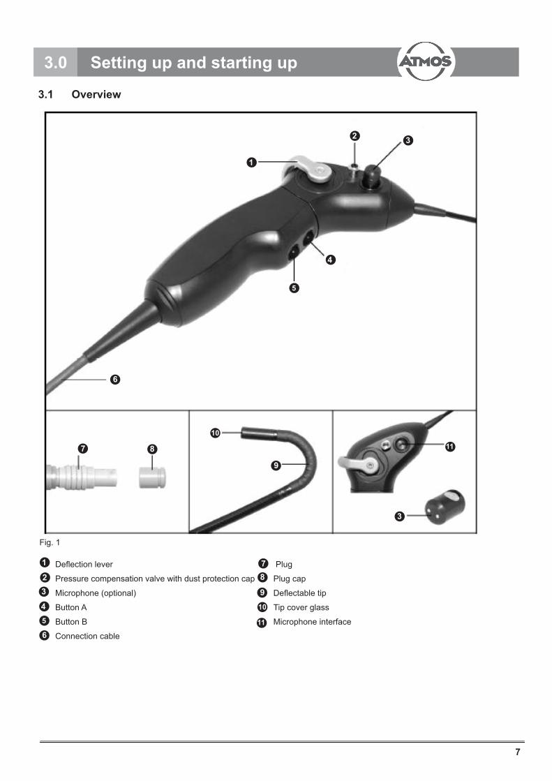
3.2 Front view ATMOS® Scope controller
Socket for connection cable
ON/OFF switch
Fig. 2
13
14
6
3.3 Rear view ATMOS® Scope controller
BNC video outputs (composite/CVBS signal)
3.5 mm jack plug (Remote 1 signal)
3.5 mm jack plug (Remote 2 signal)
Plug for stroboscope cable
USB 2.0 plug
Fuse holder with fuses
Mains connection
Fig. 3
1516
17
18
19
20
21
13 14
15 16
17
18 19
20
21

9
3.4 Overview cables
BNC video cable remote cable
USB 2.0 cable Stroboscope cable (optional)
Mains cable
Fig. 4
22
23
24
26
25
3.5 Leakage tester and hose
Leakage tester Pressure compensation cap
Silicone hose Pressure release valve
Fig. 5
30
27
30
27
28
29
3.0 Setting up and starting up
22 23 24
26
28
29
2525

10
3.6 Assembly/First Installation
Required additional devices:
Monitor according to the medical device directive 93/42/EEC.
Recommended monitor size:In combination with the present ATMOS® Scope the monitors described in chapter Product Description (medical 15" Neovo monitor) will give best results.
Installation at the place of operation:
Connecting the controller to the mains supply
Ensure that the correct mains cable is used for the respective country.
● Connect mains cable with mains connection at the controller.
● Plug the mains cable into a mains socket and thus connect the system to the mains supply.
Connecting the monitor
● Connect BNC video cable with the BNC video output of the controller and composite/CVBS input of the monitor.
Connecting the PC (optional)
The PC has to conform to the medical device directive 93/42/EEC.
Installing the USB Driver on the PC
Connect the ATMOS® Scope to the PC using the USB 2.0 connection cable (23). Depending on the confi guration of the PC, the new hardware will be identifi ed and the Installation Assistant will start. Go to part b.
If the Installation Assistant does not start automatically, please continue the installation manually as follows:
a) Manual installation (Example Windows XP):
Click Start -> Control Panel.
! 24
24
21
22 15
Fig. 6
3.0 Setting up and starting up

11
Double click on System, choose the Hardware tab, and then click on Device Manager.
Once inside the Device Manager, click on the “+” symbol next to Audio, Video and Game Controller. Double click on the USB device which has a yellow exclamation mark next to it. Search for new hardware.
The ATMOS® Scope driver will be listed as USB2820. Select this device. If this is not the case, click on Properties -> Drivers -> Update.
Fig. 7
3.0 Setting up and starting up
Fig. 8

12
b) Normally, when the ATMOS® Scope is connected to the PC, the Hardware Update Assistant window should open automatically.
Choose No, not this time. Put the Software CD, included in your set, into the CD/DVD drive and then click Next.
Fig. 9
Fig.10
3.0 Setting up and starting up

13
Fig. 11
Here it is important to mark Search removable device (disk, CD…). Then click on Next.
3.0 Setting up and starting up
Fig. 12
The driver will be installed.
14
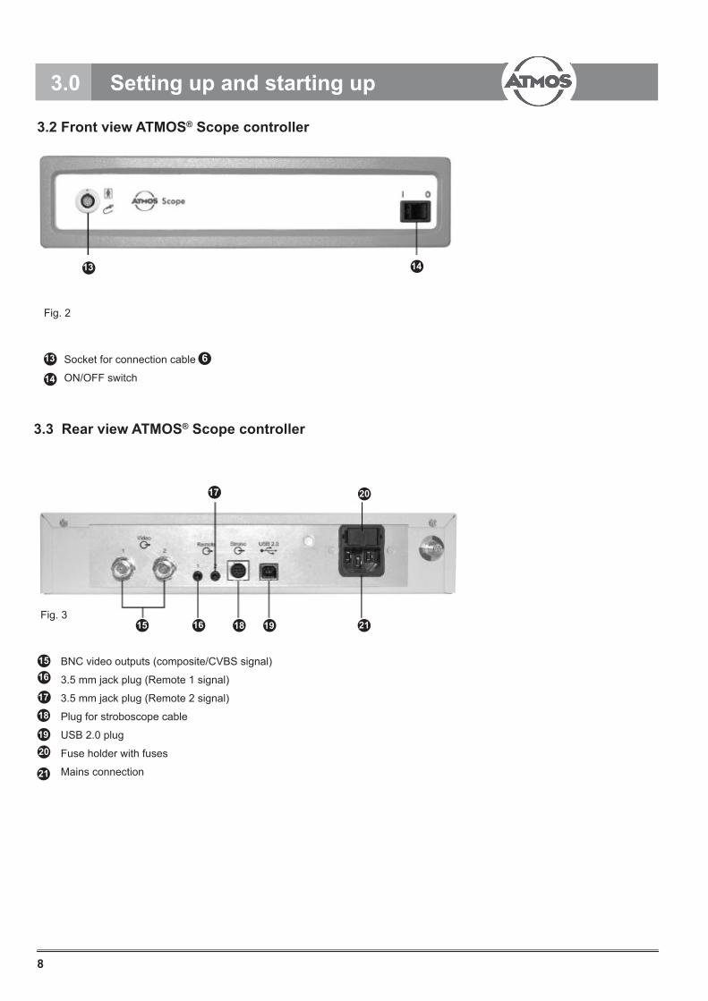
When it is completed, click on Finish.
Fig. 13
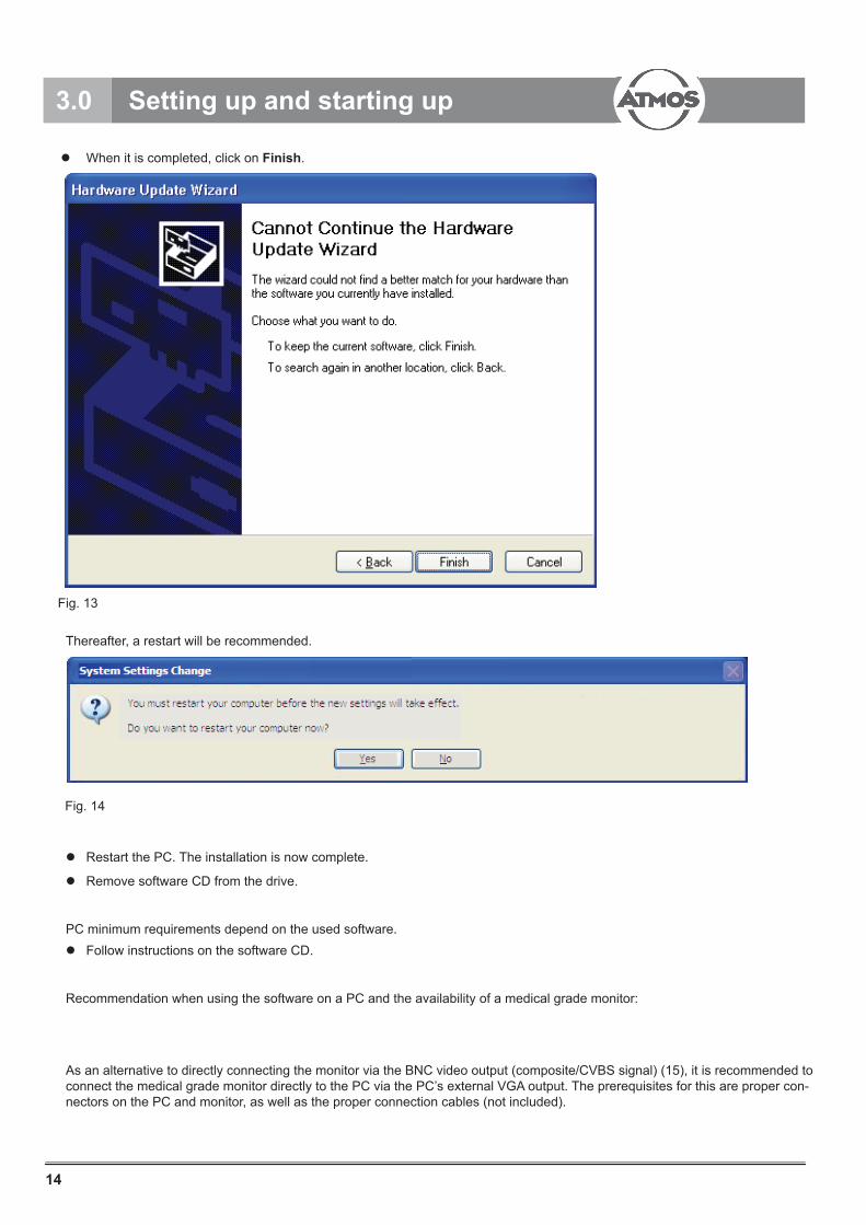
Thereafter, a restart will be recommended.
Restart the PC. The installation is now complete.
Remove software CD from the drive.
PC minimum requirements depend on the used software. Follow instructions on the software CD.
Recommendation when using the software on a PC and the availability of a medical grade monitor:
As an alternative to directly connecting the monitor via the BNC video output (composite/CVBS signal) (15), it is recommended to connect the medical grade monitor directly to the PC via the PC’s external VGA output. The prerequisites for this are proper con-nectors on the PC and monitor, as well as the proper connection cables (not included).
Fig. 14
3.0 Setting up and starting up
15
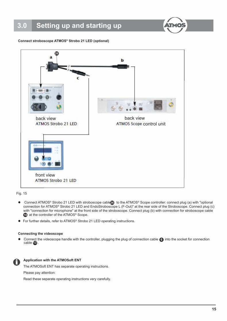
Connect stroboscope ATMOS® Strobo 21 LED (optional)
Connect ATMOS® Strobo 21 LED with stroboscope cable to the ATMOS® Scope controller: connect plug (a) with "optional connection for ATMOS® Strobo 21 LED and EndoStroboscope L (F-Out)" at the rear side of the Stroboscope. Connect plug (c) with "connection for microphone" at the front side of the stroboscope. Connect plug (b) with connection for stroboscope cable at the controller of the ATMOS® Scope.
For further details, refer to ATMOS® Strobo 21 LED operating instructions.
Connecting the videoscope Connect the videoscope handle with the controller, plugging the plug of connection cable into the socket for connection cable .
Application with the ATMOSoft ENT
The ATMOSoft ENT has separate operating instructions.
Please pay attention:
Read these separate operating instructions very carefully.
Fig. 15
26
18
136
3.0 Setting up and starting up
26
back view back viewcontrol unit
front view

16
3.7 Tests
Depending on the working distance (see technical data) the endoscopy image must be high-resolving, bright and clear.The following test sequence must be conducted on the device before processing and immediately before application.
Testing the glass surfaces
Visual inspection of the glass surfaces. The surfaces must be clean and smooth. If damages are discovered during inspection please see chapter Troubleshooting.
Leakage test
Connect plug cap onto plug . Close pressure release valve on the leakage tester . Remove dust protection cap from pressure compensation valve . Screw on pressure compensation cap to pressure compensation valve . Connect silicone tube with pressure compensation cap and leakage tester . Pump up the system to a pressure of 300 mmHg. Wait 30 seconds. By pressing the pressure release valve , drop the pressure to 160 mmHg. Wait 30 seconds and watch the pressure. The pressure must not drop down by more than 2 mmHG. If the pressure drops more than 2 mmHg, then the system has a leak and needs to be serviced.
After the leakage test, remove pressure compensation cap . Refasten dust protection cap. The leakage test must be performed after each application.
Fig. 16
!
2
227
27
29
29 28
29
3.0 Setting up and starting up
78
8
7
2
27
30
30
30
28
29
17
Testing the deflection mechanism
Slowly operate the deflection lever (Fig. 1), to check the function. Check if full deflection is achieved (see chapter Technical Data).
Limitations in deflection can indicate an endoscope defect. To avoid serious damage to the endoscope, only use the endoscope if the deflection works smoothly and without limitation..
Risk for patients
Risk for patients due to the use of products with sharp edges or damaged surfaces.
Do not use these products.
Damaged products
Do not use products with damaged camera chip (e. g. recognizable by image interferences), damaged glass surfaces or stubborn deposits, which cannot be removed by cleaning.
Send damaged products to the manufacturer or authorized repair center. Authorized repair centers can be inquired from the manufacturer.
!
!
!
1
3.0 Setting up and starting up

18
4.0 Operation
4.1 Use/Operation
Handle the system very carefully, as it contains sensible optical, mechanical and electronic components. Do not bump the distal end on hard surfaces. Do not jolt or drop the ATMOS® Scope, protect it from shocks and impacts. Do not bend or kink the flexible endoscope part, nor tear or squeeze it. The outer coating and inner components could be damaged. Never move the tip of the flexible endoscope against a resistance. The tip contains optical components, which may scratch or break when used incorrectly.
Switching on and adjusting the system.
Proper system operation cannot be guaranteed if the controller is switched on before the ATMOS® Scope handle is connected.
Ensure, that the ATMOS® Scope is connected to the controller before switching on the system.
Plug the microphone into the microphone interface of the videoscope handle. Magnets inside the microphone automatically orientate the microphone to face in the direction of the flexible endoscope part.
Switch on controller with the ON/OFF switch . Switch on all additional devices.
Switch on the monitor in the order to receive the signal from the controller.
The tip can be moved in two directions with the defl ection lever . Please do not press the defl ection lever with violence.
Switch off controller with the ON/OFF switch after use.
!
!
Fig. 17
113
3
14
14
1
3
11
19
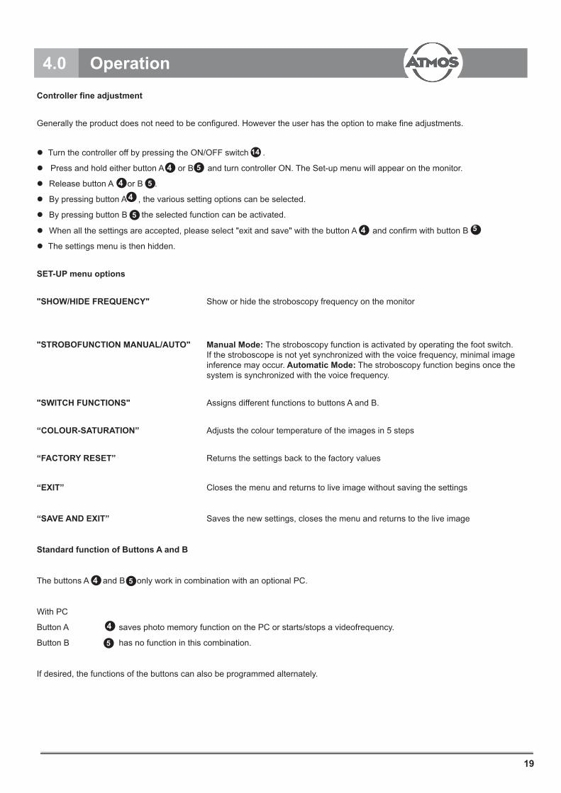
Controller fine adjustment
Generally the product does not need to be configured. However the user has the option to make fine adjustments.
Turn the controller off by pressing the ON/OFF switch .
Press and hold either button A or B and turn controller ON. The Set-up menu will appear on the monitor.
Release button A or B .
By pressing button A , the various setting options can be selected.
By pressing button B the selected function can be activated.
When all the settings are accepted, please select "exit and save" with the button A 4 and confirm with button B 5
The settings menu is then hidden.
SET-UP menu options
"SHOW/HIDE FREQUENCY" Show or hide the stroboscopy frequency on the monitor
"STROBOFUNCTION MANUAL/AUTO" Manual Mode: The stroboscopy function is activated by operating the foot switch. If the stroboscope is not yet synchronized with the voice frequency, minimal image inference may occur. Automatic Mode: The stroboscopy function begins once the system is synchronized with the voice frequency.
"SWITCH FUNCTIONS" Assigns different functions to buttons A and B.
“COLOUR-SATURATION” Adjusts the colour temperature of the images in 5 steps
“FACTORY RESET” Returns the settings back to the factory values
“EXIT” Closes the menu and returns to live image without saving the settings
“SAVE AND EXIT” Saves the new settings, closes the menu and returns to the live image
Standard function of Buttons A and B
The buttons A and B only work in combination with an optional PC.
With PC
Button A saves photo memory function on the PC or starts/stops a videofrequency.
Button B has no function in this combination.
If desired, the functions of the buttons can also be programmed alternately.
14
4 5
4 5
4
5
4 5
4
5
4.0 Operation
20
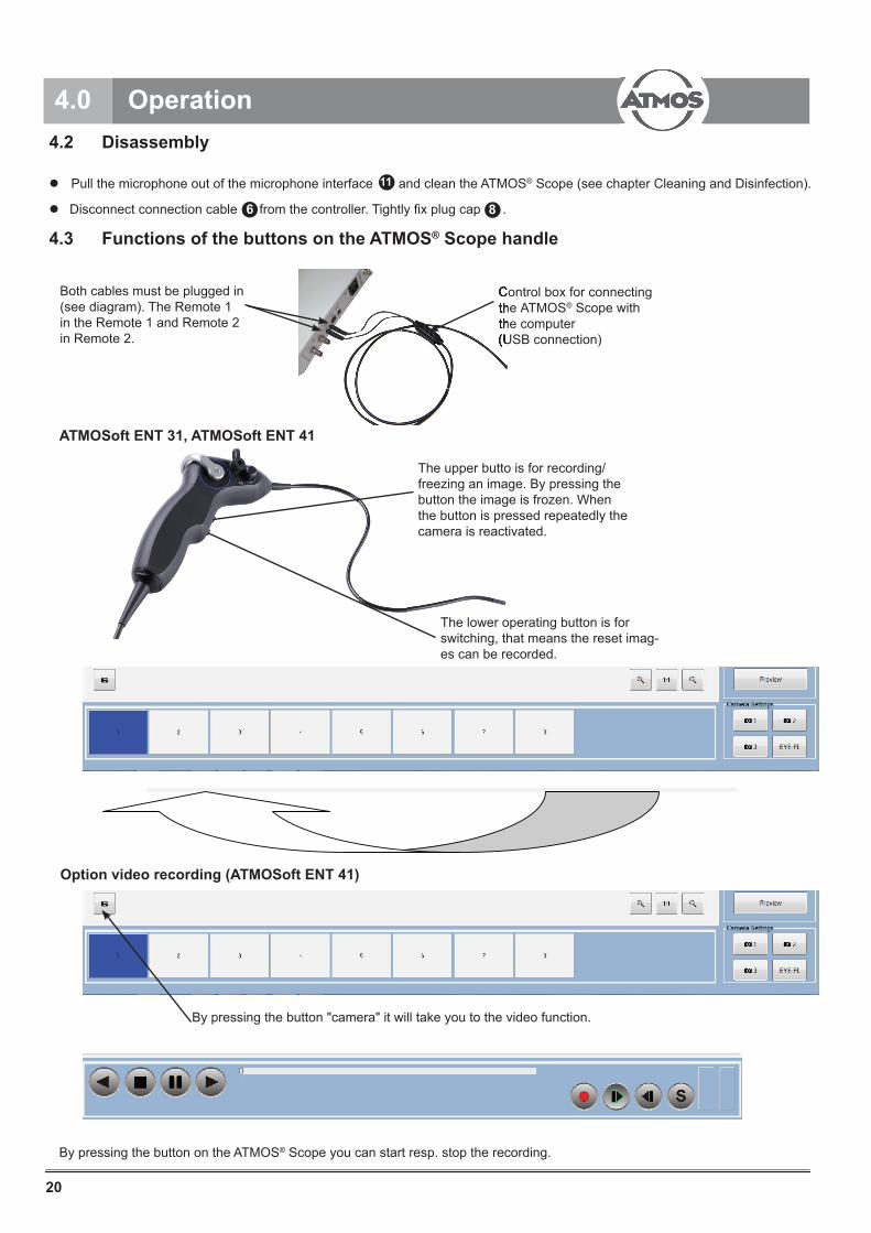
4.2 Disassembly
Pull the microphone out of the microphone interface and clean the ATMOS® Scope (see chapter Cleaning and Disinfection).
Disconnect connection cable from the controller. Tightly fix plug cap .
11
6 8
4.0 Operation
ATMOSoft ENT 31, ATMOSoft ENT 41
Control box for connecting the ATMOS® Scope with the computer(USB connection)
Both cables must be plugged in (see diagram). The Remote 1 in the Remote 1 and Remote 2 in Remote 2.
Control box for connecting the ATMOSthe computer(USB connection)
The upper butto is for recording/freezing an image. By pressing the button the image is frozen. When the button is pressed repeatedly the camera is reactivated.
The lower operating button is for switching, that means the reset imag-es can be recorded.
4.3 Functions of the buttons on the ATMOS® Scope handle
Option video recording (ATMOSoft ENT 41)
By pressing the button "camera" it will take you to the video function.
By pressing the button on the ATMOS® Scope you can start resp. stop the recording.
21
5.1 General Instructions
Adhere to national legal regulations, national and international standards and regulations as well as internal hygiene regulations for processing.
Reprocessing has to be carried out according to the manufacturer’s rules and instructions. Please use only recommended agents and procedures. Prior to each reprocessing a leakage test must be performed to prevent the endoscope from damage by liquids.
Mechanical processing provides better and safer results and should therefore be preferred to manual cleaning.
Successful processing of this medical product can only be ensured if processing is peformed through a validated processing procedure. The user/processor is responsible for the validation.
To prevent contamination of a loaded instrument tray during the procedure, do not put contaminated instruments back onto the tray, but collect them separately.
Encrusted or fixated residues from surgery can make the cleaning process more difficult or ineffective, and can cause corrosion of the stainless steel. To avoid this, the time interval between procedure and processing must not exceed 6 h. Furthermore do not use any pre-cleaning temperature >45°C or cleaning or disinfection agents (active ingredients: aldehyde, alcohol) whichcould fixate the residues even further.
Excessive doses of neutralizers or basic detergents can cause chemical degradation and/or fading of laser inscriptions on stainless steel surfaces.
Residues containing chlorine or chlorides e.g. in surgical residues, medicines, saline solutions and in the industrial water used for cleaning, disinfecting and sterilization will cause corrosion damage (pitting, stress corrosion) and result in the destruction of stainless steel products. To remove such residues, the products must be rinsed sufficiently with fully desalinated water and dried thoroughly.
Only use process chemicals that have been tested and approved (e.g. VAH/DGHM or FDA approval or CE mark) and which are compatible with the product’s materials according to the chemical manufacturers’ recommendations.All process parameters specified by the chemical’s manufacturer, such as temperature, concentration and exposure times, must be strictly observed.Failure to do so could result in the following problems:
Optical deterioration of materials, e.g. fading or discoloration of titanium or aluminium surfaces. Visible surface changes could occur for aluminium, with a pH > 8 in the application/process solution.
Material damage, e.g. corrosion, cracks, breakage, premature aging or swelling.
Clean product directly after use.
Further detailed information for hygienically safe and gentle cleansing/reprocessing can be found under: www.a-k-i.org.
Preparation at the place of use
If applicable, remove adapters and sealing cap (e. g. Luer Lock).
If applicable, open valves/taps.
Put the dry product into a closed disposal container and have it transferred to cleaning and disinfection within 6 h.
5.0 Cleaning

22
Cleaning/Disinfection
The product should not be cleaned and/or disinfected in an ultrasonic bath.
Conduct a leakage test before soaking the product in any liquids. (See chapter Tests.) A leaking device can be damaged by ingress of liquids.
● Before cleaning, put plug cap onto plug .
● Ensure that the plug cap is firmly connected to the plug .
Only use detergents and disinfectants which are approved for the product. Observe manufacturer's instructions.
Observe the concentration, temperature, duration of use and contact time according to manufactuer's instructions.
Avoid excessive pressure and tension onto the flexible videoscope components.
Please clean carefully to prevent the device from damage. Hose and bendable end can be damaged by bending, twisting, pushing or pulling. Coarse contaminations can be removed with a soft cloth or a soft brush.
Do not exceed a bending radius of 40 mm during reprocessing.
5.2 Manual Cleaning and Disinfection
Cleaning and disinfection controller and microphone
Controller and microphone should only be wiped off with a moist cloth. Do not immerse the controller and microphone in liquids.
Wipe off the outer surfaces of the controller with a soft cloth, moistened with water, a mild soap solution or isopropanol.
Stains, which are difficult to remove, can be removed with a mild cleaning agent on ammoniac basis.
Do not use scrubbing agents or dissolvers, as these may damage the coating or labels. Do not use wet sponges or cloths. Excessive cleaning agents could come into contact with electrical parts and could damage the Unit. Only reconnect the system to the mains supply when all cleaned parts are completely dry.
Cleaning and disinfection of the ATMOS® Scope
Manual cleaning with Tristel Wipes
For processing the ATMOS® Scope handle we recommend the Tristel Wipes System.Please follow the manufacturer's information and operating instructions.
Inspect visible surfaces for residual contamination after manual cleaning/disinfection. Repeat the cleaning process if necessary.
Optical surfaces should not be cleaned with a brush. Remove residues on optical surfaces with a pad moistened with alcohol(70 % ethanol) or neutral cleaning agent.
!
8
8 77
!
5.0 Cleaning

23
5.0 Cleaning
Manual cleaning with immersion disinfection and cleaning with a brush
Stage Step T (°C/°F) t (min) Conc. (%) Waterquality Chemical
I Cleaning34-45/95-113 3 0,8 D-W
Enzymatic cleaningagent, e. g.
Cidezyme/Enzol
II Intermediaterinse RT (cold) 3 x 1 --- D-W ---
III Disinfection20-25/68-77 12 --- D-W
0.55 % orthophtalalde-hyde
solution, e.g. Cidex OPA
IV Final rinse RT (cold) 3 x 2 ---VE-Wsterile ---
V Drying RT --- --- --- ---
D-W Drinking water
RT Room temperature
VE-W Fully desalinated water (demineralized, low microbiological contamination, max. 10 germs/ml and low in endotoxins value, max. 0.25 Endotoxin units/ml)
Stage I
Fully immerse the product in the cleaning solution. Ensure that all accessible surfaces are moistened Clean the product while it is in the cleaning solution, using a soft cloth or a suitable cleaning brush, until all visible residues have been removed from the surfaces. Brush all surfaces which are not accessible to visual inspection, such as hidden crevices, lumens or complex geometry for at least 1 minute until no more residues can be removed. During cleaning mobilize non-fixed components, such as focus ring, set screws, links, etc. 3 times in each direction as far as possible.
Thoroughly rinse these components with the cleaning solution (at least five times), using a disposable syringe (20 ml).
Do not use metal cleaning brushes or other abrasives which could damage the product surfaces and could cause corrosion.
Stage II Thoroughly rinse the product 3 times (all accessible surfaces) for at least 1 minute. Mobilize non-fixed components, such as focus ring, set screws, links, etc. during cleaning 3 times in each direction as far as possible. Use fresh water for every rinse cycle. Thoroughly rinse all surfaces which are not accessible to visual inspection, such as hidden crevices, lumens (e. g. working channel) or complex geometry with a disposable syringe (20 ml) for at least 5 times.
Allow water to drip off for a sufficient length of time.
Stage III
Fully immerse the product in the disinfecting solution. Ensure that all accessible surfaces are moistened. During cleaning mobilize non-fixed components, such as focus ring, set screws, links, etc. 3 times in each direction as far as possible. Thoroughly rinse all surfaces which are not accessible to visual inspection, such as hidden crevices, lumens (e. g. working channel) or complex geometry with a disposable syringe (20 ml) for at least 5 times.
24
5.0 Cleaning
Stage IV
After disinfection the product should be thoroughly rinsed 3 times (all accessible surfaces) for at least 2 minutes. During cleaning mobilize non-fixed components, such as focus ring, set screws, links, etc. 3 times in each direction as far as possible. Use fresh water for every rinse cycle.
Thoroughly rinse all surfaces which are not accessible to visual inspection, such as hidden crevices, lumens (e. g. working channel) or complex geometry with a disposable syringe (20 ml) for at least 5 times.
Allow water to drip off for a sufficient length of time.
Stage V
Dry the product with a soft, lint-free tissue. Areas, which cannot be reached with the lint-free tissue, can be dried with compressed air (p max. = 0.5 bar).
Material compatibility releases exist for:
Gigasept FF (new)
Helipur HplusN (B. Braun Medical AG)
Cidex OPA (Johnson & Johnson)
Cidezyme/Enzol (Johnson & Johnson)
Neodisher MediClean forte (Chem. Fabrik Dr. Weigert GmbH & Co. KG)
5.3 Mechanical Processing and Disinfection
Hints for mechanical processing
Inspect visible surfaces for residual contamination after mechanical processing/ disinfection. Repeat the cleaning process if necessary.
The product is compatible with several automatic flexible endoscope reprocessors (AER). For further details regarding the operation refer to the IFU of AER.
If it is unclear whether the product and all channels can be cleaned and disinfected with the existing AER, contact the manufacturer of the AER, and check with the manufacturer which cleaning and disinfection program is suitable for the product.
Risk of infection for patients and/or user due to
● Residues of cleaning and disinfectants on the product.
● Insufficient cleaning, disinfection and sterilization of the product and accessories.
Depending on the degree of pollution of the product especially its working channel has to be pre-cleaned or brushed.
Product damage due to excessive temperatures.
During mechanical cleaning and disinfection, the temperature should not exceed 65°C.
!
!
25
Position the endoscope according to the instructions of the manufacturer in the AER. Connect tube of the AER for the leakage test to the pressure compensation valve of the ATMOS® Scope handle. If necessary, use adapters.
The validation that the product can be cleaned and disinfected has been conducted using the automatic endoscope reprocessors of Wassenburg Typ WD 440 in standard program. Thereby the cleaning agent AdaptaClean (Johnson & Johnson) and the disin-fectant Cidex OPA-C (Johnson & Johnson) have been used.
The material compatibility has been tested and guaranteed using the AER of Wassenburg, type WD 440.
Material compatibility exists for:
neodisher MediClean forte (Dr. Weigert)
Cidex OPA-C (Johnson & Johnson)
AdaptaClean (Johnson & Johnson)
Color anodized parts or plastic components (e. g. serial rings, ocular) could fade during mechanical cleaning.
5.4 Sterilization
5.4.1 General Instructions
Do not autoclave the product.
Before sterilization ensure that the endoscope has no restrictions in use. See chapter Start of Operation (section Tests).Ensure that the sterilization agent can reach all surfaces. The implementation of the sterilization lies within the responsibility of the user in order to attain the required degree of sterilization.
5.4.2 Sterilization Methods
Validated method
Gas sterilization (EtO)
Ethylenoxid (Sterivit method)
Screw on pressure compensation cap before sterilization. Screw off pressure compensation cap after sterilization.
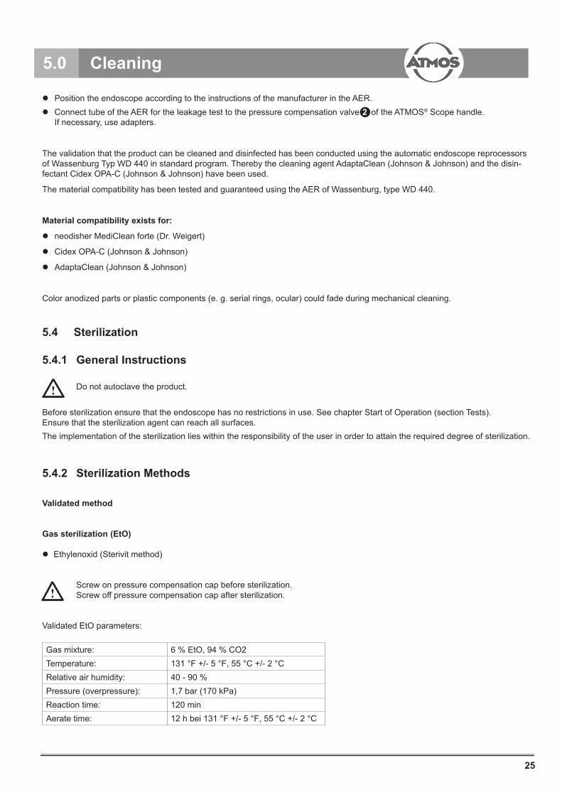
Validated EtO parameters:
Gas mixture: 6 % EtO, 94 % CO2Temperature: 131 °F +/- 5 °F, 55 °C +/- 2 °CRelative air humidity: 40 - 90 %Pressure (overpressure): 1,7 bar (170 kPa)Reaction time: 120 minAerate time: 12 h bei 131 °F +/- 5 °F, 55 °C +/- 2 °C
2
5.0 Cleaning
!
!
26
Material compatibility exists for:
Low temperature plasma sterilization
STERRAD® 50 (Advanced Sterilization Products)
STERRAD® 100S (Advanced Sterilization Products)
STERRAD® 200 (Advanced Sterilization Products)
Before sterilization unscrew the compensation cup.
After the sterilization remount the compensation cup.
Observe manufacturer's instructions for all named methods.
The use of different sterilization methods in turn can lead to a shortened lifespanof the product. Only use one of the approved methods.
Sterilization of the ATMOS® Scope with the STERRAD® sterilization method 100S
Please observe the operating instructions of the STERRAD® sterilizer and the STERRAD sterility guide from ASP. Clean and disinfect the ATMOS® Scope manually or mechanically.
Allow the ATMOS® Scope to dry thoroughly before you sterilise it in the STERRAD sterilizer. Humidity can lead to a termination of the sterilisation cycle. Tighten the pressure compensation cap.
Place the ATMOS® Scope in a sterilisation basket.
Place a STERRAD® indicator strip in the basket. Double wrap the sterilisation basket with non-woven polypropylene.
Position the basket as follows:
- sterilisation must be performed on every part.
- no parts can touch the sterilisation wall.
Start the sterilisation cycle according to the manufacturers instructions, e.g. STERRAD® 100S Short Cycle.
Please ensure that the sterility is ensured after reprocessing.
Remove the sterile goods from the sterilisation device. Remove the pressure compensation cap.
5.0 Cleaning
!

27
6.0 Maintenance and services
Maintenance, repairs and period tests may only be carried out by persons who have the appropriate technical knowledge and are familiar with the product. To carry out these measures the person must have the necessary test devices and original spare parts.
ATMOS recommends: Work should be carried out by an authorized ATMOS service partner. This ensures that repairs and testing are carried out professionally, original spare parts are used and warranty claims remain unaffected.
Period tests
At least every 24 months a repeat test of the electrical safety should be performed according to IEC 62353. ATMOS recommends an inspection according to the manufacturer‘s specifications.
Changing the fuse
Before changing the fuse, switch off the unit and disconnect it from the power network.
Using a small screwdriver, press the upper and lower latch toward the middle of the fuse holder 20
Pull the fuse holder straight out.
Replace the damaged fuse(s).
Reinsert the fuse holder.
Make sure both latches snap back into locked position.
The present product is maintenance-free. It does not contain components which have to be maintained by the user or manufacturer. However the manufacturer prescribes that a qualified person or a hospital technician inspects the product regularly and conducts a safety technical control. The inspection should be conducted at least every 24 months.
For repairs, contact the manufacturer or authorized repair center. Authorized repair centers can be inquired at the manufacturer.
For a fast processing of your service requests, return the product indicating:
Item number (REF)
serial number (S/N)
Detailed description of defects
For the protection of your staff, as well as the staff of the repair center, thoroughly clean, disinfect and sterilize the product (and, if applicable, accessories) before shipment. If this is not possible, process the product as well as possible and mark it accordingly. The repair center can refuse the repair of polluted or contaminated products due to safety reasons.
Warranty
The manufacturer commits to a 24 months guarantee on the function of the product. This guarantee is restricted to claims, which are sent in written form within the guarantee period starting from the date of the invoice, resp. with reference to repairs, indicating the invoice number. Legal guarantee claims are not restricted by this warranty.
This guarantee is only applicable to defects which cannot be attributed to normal wear and tear, misuse or wrong handling, lack of proper care or Act of nature.
Guarantee and warranty claims will not be accepted if the user himself or a non-authorized repair center performs maintenance or repair work. In case a product needs to be maintained the same applies for maintenances, which are not permitted explicitely.
Liability claims which arise from improper handling or combination with other devices or accessories cannot be claimed.
!
28
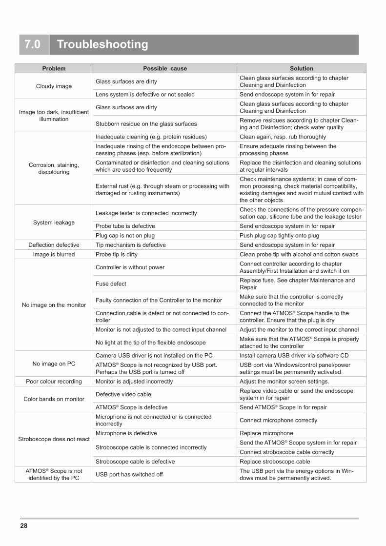
7.0 Troubleshooting
Problem Possible cause Solution
Cloudy imageGlass surfaces are dirty Clean glass surfaces according to chapter
Cleaning and DisinfectionLens system is defective or not sealed Send endoscope system in for repair
Image too dark, insufficient illumination
Glass surfaces are dirty Clean glass surfaces according to chapter Cleaning and Disinfection
Stubborn residue on the glass surfaces Remove residues according to chapter Clean-ing and Disinfection; check water quality
Corrosion, staining, discolouring
Inadequate cleaning (e.g. protein residues) Clean again, resp. rub thoroughlyInadequate rinsing of the endoscope between pro-cessing phases (esp. before sterilization)
Ensure adequate rinsing between the processing phases
Contaminated or disinfection and cleaning solutions which are used too frequently
Replace the disinfection and cleaning solutions at regular intervals
External rust (e.g. through steam or processing with damaged or rusting instruments)
Check maintenance systems; in case of com-mon processing, check material compatibility, existing damages and avoid mutual contact with the other objects
System leakageLeakage tester is connected incorrectly Check the connections of the pressure compen-
sation cap, silicone tube and the leakage testerProbe tube is defective Send endoscope system in for repairPlug cap is not on plug Push plug cap tightly onto plug
Deflection defective Tip mechanism is defective Send endoscope system in for repairImage is blurred Probe tip is dirty Clean probe tip with alcohol and cotton swabs
No image on the monitor
Controller is without power Connect controller according to chapter Assembly/First Installation and switch it on
Fuse defect Replace fuse. See chapter Maintenance and Repair
Faulty connection of the Controller to the monitor Make sure that the controller is correctly connected to the monitor
Connection cable is defect or not connected to con-troller
Connect the ATMOS® Scope handle to the controller. Ensure that the plug is dry
Monitor is not adjusted to the correct input channel Adjust the monitor to the correct input channel
No light at the tip of the flexible endoscope Make sure that the ATMOS® Scope is properly attached to the controller
No image on PCCamera USB driver is not installed on the PC Install camera USB driver via software CDATMOS® Scope is not recognized by USB port. Perhaps the USB port is turned off
USB port via Windows/control panel/power settings must be permanently activated
Poor colour recording Monitor is adjusted incorrectly Adjust the monitor screen settings.
Color bands on monitorDefective video cable Replace video cable or send the endoscope
system in for repairATMOS® Scope is defective Send ATMOS® Scope in for repair
Stroboscope does not react
Microphone is not connected or is connected incorrectly Connect microphone correctly
Microphone is defective Replace microphone
Stroboscope cable is connected incorrectlySend the ATMOS® Scope system in for repairConnect stroboscobe cable correctly
Stroboscope cable is defective Replace stroboscope cableATMOS® Scope is not identified by the PC USB port has switched off The USB port via the energy options in Win-
dows must be permanently actived.
29
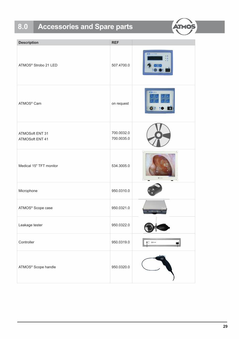
8.0 Accessories and Spare parts
Description REF
ATMOS® Strobo 21 LED 507.4700.0
ATMOS® Cam on request
ATMOSoft ENT 31ATMOSoft ENT 41
700.0032.0700.0035.0
Medical 15" TFT monitor 534.3005.0
Microphone 950.0310.0
ATMOS® Scope case 950.0321.0
Leakage tester 950.0322.0
Controller 950.0319.0
ATMOS® Scope handle 950.0320.0

30
8.0 Accessories and Spare parts
Description REF
Silicon hose for leakage tester on request
Instruction card for cleaning with pressure compensation pin on request
Fuse 0.63 A (T); 5 x 20 mm (2 pcs) on request
HF adapter 950.0323.0
BNC-BNC.2, 1.5 m 008.0670.0
USB cable 2.0 m 950.0324.0
Remote cable for analogue control 950.0325.0
ATMOSoft Remote, USB 700.0032.0
Mains cable 507.0859.0
Stroboscope cable ATMOS® Strobo 21 LED 950.0327.0
Structure-borne microphone adapter 507.0775.0
Optional still image/video archiving (digital)For digital archiving, a PC can be connected via USB (from version 2.0) and images/videos can be recorded with a soft-ware.
Optional stroboscope controllerWith the optional stroboscope controller (ATMOS® Strobo 21 LED), the physician has a system for stroboscopy at his disposal. Thanks to its LED technology, a silent stroboscopy without speed reduction, as well as a vocal cord diagnostic with fl icker-free pilot light, freeze image and slow-motion mode are possible. The freeze image with variable phasing and slow-motion mode with preselectable frequency can be adjusted via a foot-pedal.The use of an additional adapter for the structure-borne microphone is required for certain patients.
31
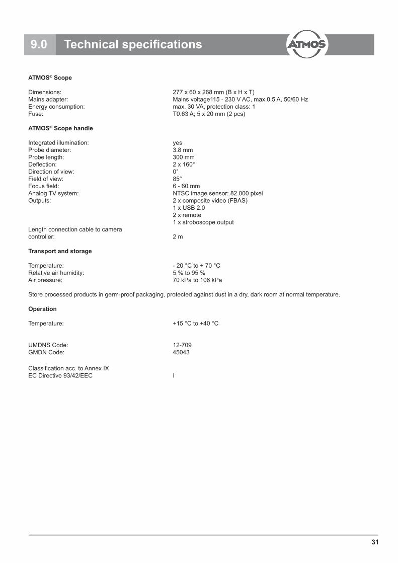
9.0 Technical specifi cations
ATMOS® Scope
Dimensions: 277 x 60 x 268 mm (B x H x T) Mains adapter: Mains voltage115 - 230 V AC, max.0,5 A, 50/60 Hz Energy consumption: max. 30 VA, protection class: 1Fuse: T0.63 A; 5 x 20 mm (2 pcs)
ATMOS® Scope handle
Integrated illumination: yesProbe diameter: 3.8 mm Probe length: 300 mm Defl ection: 2 x 160°Direction of view: 0° Field of view: 85° Focus fi eld: 6 - 60 mm Analog TV system: NTSC image sensor: 82.000 pixelOutputs: 2 x composite video (FBAS) 1 x USB 2.0 2 x remote 1 x stroboscope outputLength connection cable to cameracontroller: 2 m
Transport and storage
Temperature: - 20 °C to + 70 °C Relative air humidity: 5 % to 95 % Air pressure: 70 kPa to 106 kPa
Store processed products in germ-proof packaging, protected against dust in a dry, dark room at normal temperature.
Operation
Temperature: +15 °C to +40 °C
UMDNS Code: 12-709GMDN Code: 45043
Classifi cation acc. to Annex IXEC Directive 93/42/EEC I
32
● The ATMOS® Scope does not contain any hazardous materials.
● The housing is fully recyclable.
● Device and accessories must be decontaminated prior to disposal.
● Please ensure a careful separation of the different materials.
● Please observe national disposal regulations (e.g. waste incineration).
Disposal within the EC
The device described above is a high-quality medical product with a long service life. After its life cycle it must be disposed of professionally. According to the EC directives (WEEE and RoHS) the device may not be disposed of in domestic waste. Please observe existing national laws and rules for disposal of old devices.
Disposal within the Federal Republic of Germany
In order to guarantee a proper disposal of your old device, please either pass on your old device to your specialised dealer or send it directly to ATMOS MedizinTechnik for a professional disposal.
Before disposal respectively before transport, all parts, which came into contact with the patient must be thoroughly cleaned, disinfected. The device surface must be disinfected.
10.0 Disposal

33
11.0 Notes on EMC
11.1 Guidelines and Manufacturer's Declaration - EmissionsThe ATMOS® Scope is intended for use in the electromagnetic environment specifi ed below. The customer or user of the ATMOS® Scope should ensure that it is used in such an environment.
■ Medical electrical equipment is subject to special precautions with regard to EMC and must be installed acc. to following EMC notes. ■ Portable and mobile HF communication facilities could influence medical electrical equipment. ■ The use of other accessories, other converters and cables than stated may lead to an increased emission or a reduced interference immunity of the equipment or system.
Emissions Test Compliance Electromagnetic Environment - GuidanceRF Emissions CISPR 11
Group 1 The ATMOS® Scope uses HF energy only for its internal function. Therefore, its RF emissions are very low and are not likely to cause any interference to nearby electronic equipment.
RF Emissions CISPR 11
Class B The ATMOS® Scope is suitable for use in all estab-lishments, including domestic, and those directly connected to the public low-voltage power supply network which supplies buildings used for domestic purposes.
Harmonics IEC 61000-3-2 Class AFlicker IEC 61000-3-3
match
11.2 Guidelines and Manufacturer's Declaration - Electromagnetic immunity
The ATMOS® Scope is intended for use in the electromagnetic environment specifi ed below. The customer or user of the ATMOS® Scope should ensure that it is used in such an environment.
Immunity Test IEC 60601-Test Level Compliance Level Electromagnetic Environ-
ment - GuidanceESD IEC 61000-4-2
± 6 kV Contact discharge
± 8 kV Air discharge
± 6 kV Contact discharge
± 8 kV Air discharge
Floors should be wood, concrete, or ceramis tile. If fl oors are syn-thetic, the relative humidity should be at least 30%.
EFTIEC 61000-4-4
± 2 kV Mains
± 1 kV I/Os
± 2 kV Mainsinapplicable± 1 kV I/Os
Mains power quality should be that of a typical commercial or hospital environment.
SurgesIEC 61000-4-5
± 1 kV Differential± 2 kV Common
± 1 kV Differential± 2 kV Common
Mains power quality should be that of a typical commercial or hospital environment.
Power Frequency 50/60 HzMagnetic fi eld IEC 61000-4-8
3 A/m applicable 3 A/m
Power frequency magnetic fi elds should be that of a typical com-mercial or hospital environment.

34
11.0 Notes on EMC
Immunity Test IEC 60601-Test Level Compliance Level Electromagnetic Environ-
ment - GuidanceVoltage Dips / DropoutIEC 61000-4-11
< 5 % UT (> 95 % Dip of the UT) for 0.5 Cycle
40 % UT(60% Dip of the UT) for 5 Cycles
70% UT(30 % Dip of the UT) for 25 Cycles
< 5 % UT (>95 % Dip of the UT) for 5 s
< 5 % UT (> 95 % Dip of the UT) for 0.5 Cycle
40 % UT(60% Dip of the UT) for 5 Cycles
70% UT(30 % Dip of the UT) for 25 Cycles
< 5 % UT (>95 % Dip of the UT) for 5 s
Mains power quality should be that of a typical commercial or hospital environment. If the user of the AT-MOS® Scope demands continued function even during interruptions of the power supply, it is recom-mended to supply the ATMOS® Scope from an uninterruptible power supply or a battery.
NOTE UT is the mains alternating current prior to application of the test levels.
11.3 Guidelines and Manufacturer´s Declaration - Electromagnetic immunityThe ATMOS® Scope is intended for use in the electromagnetic environment specified below. The customer or user of the ATMOS® Scope should ensure that it is used in such an environment.
Immunity Test IEC 60601-Test Level Compliance Level Electromagnetic Environment -
Guidance
Conducted RFIEC 61000-4-6
V1 = 3 Veff150 kHz to 80 MHz 3 V
Portable and mobile communications equipment should be separated from the ATMOS® Scope incl. the cables by no less than the distances calculated/listed below.
Recommended distances:
According to the manufacturer's recom-mendations where „P“ is the max. power in watts (W) and D is the recommended separation distance in meters (m).
Field strengths from fixed transmitters, as determined by an on site (a) evaluation, should be less than the compliance level (b). Interference may occur in the vicinity of equipment containing the following symbol
Radiated RFIEC 61000-4-3
E1 = 3 V/m80 MHz to 2,5 GHz
3 V/m

35
11.0 Notes on EMC
11.4 Recommended separation distances between portable and mobile RF communications equipment and the ATMOS® Scope
The ATMOS® Scope is intended for use in electromagnetic environment in which RF disturbances are controlled. The customer or user of the ATMOS® Scope can help prevent electromagnetic interference by maintaining a mini-mum distance between portable and mobile RF Communications equipment and the ATMOS® Scope as recommended below, according to the maximum output power of the communications equip-ment.
Separation distance, depending on transmit-frequency mNominal output of the
transmitter
W
150 kHz to 80 MHz
d = [ 3,5 / 3] √P
80 MHz to 800 MHz
d = [ 3,5 / 3] √P
800 MHz to 2,5 GHz
d = [ 7,0 / 3] √P
0.01 0.12 0.12 0.2330.1 0.37 0.37 0.741 1.16 1.16 2.3310 3.69 3.69 7.38100 11.66 11.66 23.33
For transmitters for which the maximum nominal output is not indicated in the above table, the recommended sep-aration distance d in meters (m) can be determined using the equation belonging to the respective column where-as P is the maximum nominal output of the transmitter in watts (W) acc. to manufacturer´s specification.
NOTE 1 With 80 MHz and 800 MHz the higher frequency range applies.
NOTE 2 These guidelines may not be applicable in all cases. The propagation of electromagnetic sizes is influenced by absorptions and reflections of buildings, objects and people.
NOTE 1 With 80 MHz and 800 MHz the higher frequency range applies.
NOTE 2 These guidelines might not be applicable in all cases. The propagation of electromagnetic sizes is influenced by absorptions and reflections of buildings, objects and people.a The field strength of stationary transmitters, such as base stations of cellular phones and mobile terrain radio equipment, amateur radio transmitters, cbm broadcast and TV stations cannot be predestined exactly. To determine the electromagnetic environment in regard to stationary transmitters, a study of the location should be considered. If the measured field strength at the location where the ATMOS® Scope is used exceeds the above compliance level, the ATMOS® Scope should be observed to verify normal operation. If abnormal performance characteristics are noted, additional measures may be necessary, e. g. a changed arrangement or another location for the device.
b Within the frequency range of 150 kHz to 80 MHz the field strength should be below 3 V/m.

ATMOS MedizinTechnik GmbH & Co. KG
Ludwig-Kegel-Str. 16
79853 Lenzkirch / Germany
Phone: +49 7653 689-0
www.atmosmed.com