FW Pipe Rack Document
38
CONTRACT NO: 1- 14 -3 04 0/ 59 CALCULATION NO: 3041-8310-CA -0130 CLIENT: SHELL EASTERN PETROLEUM (PTE) Ltd., PROJECT T ITLE: SEPC-MEG DISCIPLINE: Civil Engineering SUBJECT MAIN PIPE RACK SUBSTRUCTURE DESIGN DRAWING NO'S. 3041-8310-43-0015 RA AREA MAIN E-W PIPE RACK FOUNDATION LAYOUT. 3041-8310-43-0016 RB AREA MAIN E-W PIPE RACK FOUNDATION LAYOUT. 3041-8310-43-0017 RC AREA MAIN E-W PIPE RACK FOUNDATION LAYOUT. REFERENCE DATA DESIGN BASIS SS CP 65 : Part 1 : 1999 BS 6399- Part-2 : 1997 Loading for Buildings - Part 2 Code of practice for wind loads 3041-8310-SP-3002 Civil/Structural Engineering Guide 2721-8310-RP-0002 Preliminary Interpretative Report for Shell Houdini Project -Rev. 1 DEP 34.00.01.30 Gen. Technical specification - Minimum specification for Design and Engineering REMARKS DATE DESCRIPTION ORIGINATOR CHECKER APPROVER 2- Apr- 07 Issued f or Aut horit y Ap pr ova l S.L. NARAYANA V. PREMA Code of practice for structural use of concrete (Incorporating Erratum No.1, September 2000) DSN: 9317 Page 1 of 28 SAFETY CALCULATION: YES A1 REV COMPUTER PROGRAM: EXCEL CALCULATION CLASS: 1
Transcript of FW Pipe Rack Document

8/10/2019 FW Pipe Rack Document
http://slidepdf.com/reader/full/fw-pipe-rack-document 1/38
CONTRACT NO: 1-14-3040/59 CALCULATION NO: 3041-8310-CA-0130
CLIENT: SHELL EASTERN PETROLEUM (PTE) Ltd.,
PROJECT TITLE: SEPC-MEG
DISCIPLINE: Civil Engineering
SUBJECT
MAIN PIPE RACK SUBSTRUCTURE DESIGN
DRAWING NO'S.3041-8310-43-0015 RA AREA MAIN E-W PIPE RACK FOUNDATION LAYOUT.3041-8310-43-0016 RB AREA MAIN E-W PIPE RACK FOUNDATION LAYOUT.3041-8310-43-0017 RC AREA MAIN E-W PIPE RACK FOUNDATION LAYOUT.
REFERENCE DATA
DESIGN BASIS
SS CP 65 : Part 1 : 1999
BS 6399- Part-2 : 1997 Loading for Buildings - Part 2 Code of practice for wind loads3041-8310-SP-3002 Civil/Structural Engineering Guide2721-8310-RP-0002 Preliminary Interpretative Report for Shell Houdini Project -Rev. 1DEP 34.00.01.30 Gen. Technical specification - Minimum specification for Design
and Engineering
REMARKS
DATE DESCRIPTION ORIGINATOR CHECKER APPROVER2-Apr-07 Issued for Authority Approval S.L. NARAYANA V. PREMA
Code of practice for structural use of concrete (IncorporatingErratum No.1, September 2000)
DSN: 9317
Page 1 of 28
SAFETY CALCULATION: YES
A1REV
COMPUTER PROGRAM:EXCEL
CALCULATION CLASS: 1

8/10/2019 FW Pipe Rack Document
http://slidepdf.com/reader/full/fw-pipe-rack-document 2/38

8/10/2019 FW Pipe Rack Document
http://slidepdf.com/reader/full/fw-pipe-rack-document 3/38
OF
Cl. No Items
COVER SHEET
AMENDMENT SHEET
ENGINEER'S & CHECKER'S STANDARD CERTIFICATION
CONTENTS
SCOPE
DESCRIPTION
DESIGN INFORMATION
ANALYSIS METHODOLOGY
PILE CAPACITY
DESIGN PHILOSOPHY
POCKET DESIGN
GROUND BEAM -1, DESIGN
9.0 ANCHOR BOLT DESIGN
BASE PLATE DESIGN
PLINTH DESIGN
GROUND BEAM - 6 DESIGN
ENGINEER'S & CHECKER'S STANDARD CERTIFICATION
APPENDIX - A POKCET DESIGN FOR ERECTION MOMENTS
APPENDIX - B DRAWINGS
A1 TO A3
B1 TO B4
8.0
CONTRACT NO : 1 - 14 - 3040/ 59
SAFETY CALC. YES
CALC. NO
3.0
7.0
5.0
10.0
PROJECT:
9
3041-8310-CA-0130
Approver
MAIN PIPE RACK SUBSTRUCTURE DESIGN 4
Checker
SLN VPP
Sheet No :
Date
2-Apr-07A1
FOSTER WHEELER
SEPC-MEG Rev
28
Originator
SUBJECT :
20
6.0
21
10
9
18
9
CONTENTS
Sheet No.
4.0
2
5
1.0
1
3
4
5
52.0
28
11.0
12.0
23
26

8/10/2019 FW Pipe Rack Document
http://slidepdf.com/reader/full/fw-pipe-rack-document 4/38
OF
DESIGN INFORMATION
DESIGN CODES & SPECIFICATIONS
a) SS CP 4 : 2003 : Code of practice for foundations
b) SS CP 65 : Part 1: 1999 : Code of practice for structural use of concrete(Incorporating Erratum No.1, September 2000)
c) BS 8110 -1: 1997 : Part 1:Code of practice for design andconstruction (Incorporating Amendments Nos: 1, 2 and 3)
d) BS 6399 -1: 1996 : Loading for buildings: Part 1 : Code of practice for Dead & Imposed
Loads
e) BS 6399 -2 : 1997 : Loading for buildings: Part 2 : Code of practice for Wind Loads
f) BS 5950-1 : 2000 : Structural use of Steelwork in building.Part 1: Code of practice for design Rolled andwelded sections(incorporating corrigendum No:1)
g) SS CP 73 : 1998 : Code of practice for Design of concretestructures for retaining aqueous liquids
h) Singapore Building Control Regulations (S 148/1989, Fourth, fifth & Sixth)
i) Singapore Civil Defence Force : Code of Practice for Fire Precautions in
Buildings, 1997 - (Fire Safety Bureau)MATERIALS
a) Structural Steel
(i) Steel Section - BS EN 10210 for Hollow Section (hot-finished)(Grade S275 JR) BS EN 10025 for other non-alloy steel
(ii) Chequered floor plate - Grade S275 JR
FOSTER WHEELER
1 - 14 - 3040/ 59
PROJECT: SEPC-MEG Rev
SUBJECT :
SAFETY CALC. YES
A1 SLN2-Apr-07
Sheet No :
Originator
28MAIN PIPE RACK SUBSTRUCTURE DESIGN
Date
3041-8310-CA-0130
5
Checker
VPP
Approver
2.0
CONTRACT NO :
SCOPE
CALC. NO
1.0
3.2
3.0
3.1
DESCRIPTION
This document covers the substructure design for main pipe rack (excluding standard pile caps). Designof standard pile caps are covered in Doc. No. 3041-8310-CA-3001.
Main pipe rack columns are precast concrete members except stair case columns. Stair case columns aresteel members and which are supported on plinth with base plate and anchor bolts. Stair case column pilecaps are connected with ground beams for sharing of lateral forces. Ground beams are also providedalong longitudinal(E-W) direction of pipe rack at braced bay locations for sharing of longitudinal forcesfrom superstructure.

8/10/2019 FW Pipe Rack Document
http://slidepdf.com/reader/full/fw-pipe-rack-document 5/38

8/10/2019 FW Pipe Rack Document
http://slidepdf.com/reader/full/fw-pipe-rack-document 6/38
OF
b) Imposed Loads
Unless otherwise stated in the calculation, imposed loads shall be based on the following.
c) Wind Loading
Wind loading shall be in accordance with BS 6399-2: 1997 & Shell DEP 34.00.01.30 GENGround roughness category: Country. As per cl. 8.3.7 of
3041-8310-SP-3002 The site wind speed to be taken equals basic wind speed as specified in Cl. 8.3.7 of 3041-8310-SP-3002
Wind loads for Buildings and Structures
All structures shall be designed for 10 second gust.
GROUND WATER TABLE
The ground water level is approximately 1.5m below 5.4m ACD As per cl. 3.14.4 of3041-8820-SP-0001
STRUCTURAL SUMMARY
The scope of this submission consists of main pipe rack substructure design .
Piping load(excluding empty weight of pipe)
b) Pipes larger than 300 mm diameter Concentrated loads in their actuallocations.
10 Hand railing, horizontal 1 kN point load at any one point
1.5 kN/m 2 (Test condition)
11 Ladder, moving concentrated load 2.5 kN12
8 Compressor/generator platforms 10.0 kN/m 2(See Note 1)9 Exchanger head platform areas or similar 5.0 kN/m 2 (See Note 1)
7 Storage areas, heavy 10.0 kN/m 2
(To be determined considering the intended
5 Exit or public stairs 5.0 kN/m 2
6 Storage areas, light 5.0 kN/m 2
Access platforms, walkways and tower 2.0 kN/m 2 or single point load of 3.0 kN3 Roof areas accessible for inspection and 1.5 kN/m 2 or single point load of 2.0 kN4 Plant stairs 3.0 kN/m 2
Item Floor Area Usage Imposed Load1 Operating and service areas 5.0 kN/m 2 (See Note 1) or single point load of 7.52
FOSTER WHEELER SUBJECT : MAIN PIPE RACK SUBSTRUCTURE DESIGN 7
PROJECT: SEPC-MEG Rev Date Originator Checker
1 - 14 - 3040/ 59 A1 2-Apr-07
Sheet No :
SLN VPP
28
Approver
a) Piping less than 300 mm diameter 0.7 kN/m 2 (Operating condition)
Note 1 :- This live load applies only to platforms and floor slabs in areas where the possibility exists ofthe flooring or slab being subjected to a concentrated load from either equipment parts or heavy tools.
SAFETY CALC. YES
3041-8310-CA-0130
3.5
3.4
Design wind pressure shall be determined for an hourly wind speed of 65Km/hr (18.06 m/s) for terraincategory 3. Structure is designed for 10 second gust factor.
CONTRACT NO :
CALC. NO

8/10/2019 FW Pipe Rack Document
http://slidepdf.com/reader/full/fw-pipe-rack-document 7/38
OF
COMPUTER PROGRAM USED
Analysis
Bandwidth Reduction
Structural Steel Sections
Generation of Joints & Members
Offset Connections
Spring Supports
Loads
Load Combination
Parameters for Steel Design
Code Checking
Member Selection
Sheet No : 28
VPP
8
Originator
3041-8310-CA-0130
PROJECT: SEPC-MEG Rev Date
FOSTER WHEELER SUBJECT :
Checker
3.6
Approver
MAIN PIPE RACK SUBSTRUCTURE DESIGN
CALC. NO
SAFETY CALC.
CONTRACT NO : 1 - 14 - 3040/ 59 A1 2-Apr-07
YES
SLN
STAAD.Pro contains a complete listing of standard sections. This enables the program internally to
pick up properties for analysis and design based on a simple designation in the member propertyportion of input.
Member selection, based on least weight criteria or design parameters such as member depth orsection profile, may be made from STAAD.Pro's internal tables or user created tables. This capabilitycan significantly reduce the amount of time and expense in design work.
The time of execution for a given STAAD.Pro run is dependent upon the bandwidth of the stiffnessmatrix as determined by the joint and member numbering scheme used in the input file. STAAD.Prohas the capability of rearranging this numbering system internally so as to minimize the time and diskspace required for execution, while maintaining a level of ease and flexibility for the user in generationof these data.
STAAD. Pro is capable of performing two and three dimensional analysis of structures consisting ofbeam, truss, and thin Plate/shell elements. Specific applications include trusses, frames with or withoutshear wall stiffening, plate and shell systems, elastically supported beams and plates, as well as a broadrange of other types of structures.
A variety of load types may be specified including joint, member (uniform, concentrated or linearlyvarying), temperature, support displacement, area, prestressing and moving loads. In addition, theprogram has the capability of calculating the self weight
Factored load combinations of primary loads facilitate data input and implementation of coderequirements.
A variety of different design parameters such as K, F Y and Cb are available for design purposes.These parameters have standard default values which may be changed by the user as desired.
Complete code checking of members may be performed according to the AISC, (Working Strength &LRFD), AASHTO or British Codes of Practice.
Joints and members may be easily generated in a linear or set fashion to minimize the amount ofrequired input.
Members, not directly connected at the geometric point of incidence, can be designated as such sothat secondary forces due to these eccentricities will be taken into account during analysis.
Supports having a spring constant in any translational or rotational direction may be specified.

8/10/2019 FW Pipe Rack Document
http://slidepdf.com/reader/full/fw-pipe-rack-document 8/38
8/10/2019 FW Pipe Rack Document
http://slidepdf.com/reader/full/fw-pipe-rack-document 9/38
OF
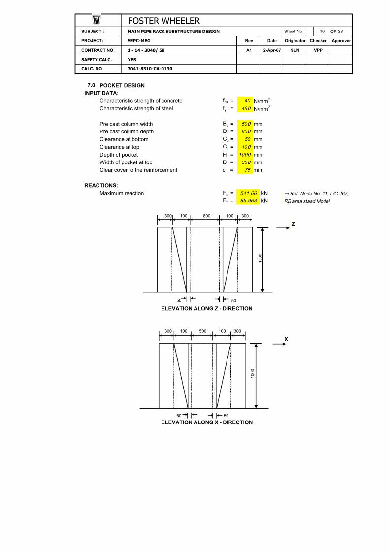
POCKET DESIGNINPUT DATA:
Characteristic strength of concrete f cu = N/mm 2
Characteristic strength of steel f y = N/mm 2
Pre cast column width Bc = mmPre cast column depth Dc = mmClearance at bottom Cb = mmClearance at top C t = mmDepth of pocket H = mmWidth of pocket at top D = mmClear cover to the reinforcement c = mm
REACTIONS:Maximum reaction Fx = kN Ref. Node No: 11, L/C 267,
Fz = kN RB area staad Model
Z
50
ELEVATION ALONG Z - DIRECTION
X
50 50
ELEVATION ALONG X - DIRECTION
500 100 300
1 0 0 0
300 100 800 100
50
300 100
541.66
85.963
300
1 0 0 0
50
10 0
1000
75
30 0
28
Originator
Sheet No :
CONTRACT NO : 1 - 14 - 3040/ 59
40
7.0
MAIN PIPE RACK SUBSTRUCTURE DESIGN 10
Checker
SLN
PROJECT:
FOSTER WHEELER
SEPC-MEG Rev ApproverDate
SUBJECT :
VPP2-Apr-07A1
3041-8310-CA-0130
SAFETY CALC. YES
CALC. NO
46 0
50 0
80 0

8/10/2019 FW Pipe Rack Document
http://slidepdf.com/reader/full/fw-pipe-rack-document 10/38
OF
Uniform force along Z direction due to F x = Fx/(D c+2C t)= 541.664/((800+2*100)/1000)= kN/m
Uniform force along X direction due to F z = Fz/(Bc+2C t)= 85.963/((500+2*100)/1000)= kN/m
BENDING MOMENT CALCULATIONS: with reference to the Reinforced Concrete Designer's hand book (Reynolds & Steedman) the bending
moment in the " beam" b/w the side walls can be assessed, treating the pocket as a Box culvert.
X- DIRECTION:
kN/m
Center to center distance B/W walls along l = Bc+C t+C t+D/2+D/2X- direction = 500+100+100+300/2+300/2
= mmCenter to center distance B/W walls along h = Dc+C t+C t+D/2+D/2Z- direction = 800+100+100+300/2+300/2
= mmk = (l/h)(h s /h w)3
= (1000/1300)*(300/300)̂ 3=
k1 = k+1=
k3 = k+3=
k5 = 2k+3=
q1 = W 1(Dc+2C t)/h+D= 541.664*(800+2*100)/(1300+300)= kN/m
Bending moment at B & D = q1h2k/12k 1k3
= 338.54*(1.3)̂ 2*0.77/(12*1.77*3.77)
541.664
1000
W 2
W 1
A1
MAIN PIPE RACK SUBSTRUCTURE DESIGN
122.80
CONTRACT NO : 1 - 14 - 3040/ 59
CALC. NO 3041-8310-CA-0130
SUBJECT : Sheet No :
SAFETY CALC. YES
541.66
2-Apr-07
28
PROJECT: SEPC-MEG Rev Date Originator Checker Approver
FOSTER WHEELER 11
SLN VPP
4.54
338.54
1300
0.77
1.77
3.77
A B
C D
X
Z
hw hw
h s
h
h s
l
q1

8/10/2019 FW Pipe Rack Document
http://slidepdf.com/reader/full/fw-pipe-rack-document 11/38
OF
= kN.mBending moment at A & C = Mbdk5/k
= 5.50*4.54/0.77= kN.m
Free span moment Mx = q1h2/8= 338.54*(1.3)̂ 2/8= kN.m
Z - DIRECTION:
kN/m
k = (h/l)(h w/h s)3
= (1300/1000)*(300/300)̂ 3=
k1 = k+1=
k3 = k+3=
k5 ==
q2 = W 2(Bc+2C t)/h+D= (122.80*(500+2*100))/(1000+300)= kN/m
Bending moment at C & D = q2*l2*k/12*k 1*k3
= 66.13*(1)̂ 2*1.30/(12*2.30*4.30)= kN.m
Bending moment at A & B == 0.72*5.60/1.30= kN.m
Free span moment = q2*l2/8= 66.13*(1)^2/8= kN.m
122.80
2.30
2k+3
CONTRACT NO :
SAFETY CALC. YES
1 - 14 - 3040/ 59 A1 2-Apr-07
Date Approver
SLN
Originator Checker
12 28
CALC. NO 3041-8310-CA-0130
VPP
PROJECT: SEPC-MEG
SUBJECT : MAIN PIPE RACK SUBSTRUCTURE DESIGN
FOSTER WHEELER Sheet No :
8.27
Mz
5.50M
bd
Rev
Mca
32.45
71.52
1.3
4.3
5.6
66.13Mcd
0.72Mab
3.12
Mcd k5/k
A B
C D
X
Z
hw hw
hs
h
hs
l
q2

8/10/2019 FW Pipe Rack Document
http://slidepdf.com/reader/full/fw-pipe-rack-document 12/38
OF
COMBINED BENDING MOMENTS ( X & Z DIRECTIONS):
1.Bending moment at A = Mca +Mab
= 32.45+3.12= kN.m
2.Bending moment at B = Mbd+Mab
= 5.50+3.12= kN.m
3.Bending moment at C = Mca +Mcd
= 32.45+0.72= kN.m
4.Bending moment at D = Mbd+Mcd
== kN.m
5.Span moment mid span AB = Mz-(M A+MB)/2= 8.27-(35.57+8.62)/2= kN.m
6.Span moment mid span AC = Mx-(M A+MC)/2= 71.52-(35.57+33.17)/2= kN.m
Maximum design moment M = kN.mEffective depth of wall d = D-c- f /2
= 300-75-20/2= mm
Breadth of wall considered b == 0.45*1000= mm
k = As per SS CP 65: Part 1:1999 cl. 3.4.4.4.
= 37.15*10^6/(450*215^2*40)=
k' ( Redistribution not exceed 10%) =k<k' , Hence compress ion re inforcement is not requ ired.
Depth of lever arm z = (0.5+ (0.25-k/0.9))d,but not greater than 0.95d== mm= 0.95d
= mmHence, z = mm
Area of steel required A sb = M/0.87f yz= 37.15*10^6/(0.87*460*203.74584232665)= mm 2
Minimum % of steel = % As per SS CP 65: Part 1:
Minimum area of steel A sb min = 0.4*450*300/100 1999 Table 3.27 = mm 2
Area of steel required for 450mm width = mm 2
Hence, area of steel required per 'm' width = mm 21200
zmax
0.40
540.00540.00
455.57
35.57
Date
M/bd 2f cu
0.45H
450
PROJECT:
FOSTER WHEELER SUBJECT : MAIN PIPE RACK SUBSTRUCTURE DESIGN Sheet No : 13 28
Orig inator Checker Approver
CONTRACT NO : 1 - 14 - 3040/ 59 A1 2-Apr-07 SLN VPP
CALC. NO 3041-8310-CA-0130
SAFETY CALC. YES
MD
6.22M AB
M A
SEPC-MEG Rev
M AC
37.1537.15
215
MB
8.62MC
-13.83
5.50+0.7
33.17
0.045
203.75
204.25203.75
0.156
(0.5+SQRT(0.25-0.045/0.9))*215

8/10/2019 FW Pipe Rack Document
http://slidepdf.com/reader/full/fw-pipe-rack-document 13/38
OF
DIRECT TENSION: Since the beam is spanning between the side walls, the UDL on the beam puts tension in the sidewalls.
Tension force F = Max. of forces in X & Z direction.Tension force in X- direction Fx = W 1*(Dc+2C t)/2
= 541.66*(800+2*100)/(2*1000)= kN
Tension force in Z- direction Fz = W 2*(Bc+2C t)/2= 122.80*(500+2*100)/(2*1000)= kN
Maximum tension force F = kN Area of tension reinforcement A st = F/0.87f y
= 270.83*10^3/(0.87*460) Area of steel required for 450mm width = mm 2
Hence, area of steel required per 'm' width = mm 2
Horizontal reinforcement required per face A s = A sb + 0.5 A st
= 1200+0.5*1503.87= mm 2
Diameter of bar f = mmRequired spacing = mmProvided spacing = mm
Area of steel provided = mm 2
Provide 20mm dia @ 150mm c/c as ho rizonta l reinf . on both faces .
SIDE WALLS:
Walls AB & CD
Force in the walls AB & CD F1 = W 1*(Dc+2C t)/2= 541.66*(800+2*100)/(2*1000)= kN
Moment in the walls due to F 1 M1 = F1*(H-0.45H/2)= 270.83*((1000-(0.45*1000)/2)/1000)= kN.m
Effective depth of wall d1 = Bc+2*C t+2D-c- f -f /2= (500+2*100+2*300)-75-20-20/2= mm
2094.4
VPP
270.83
270.83
209.89
1195.00
1503.9
CONTRACT NO : 1 - 14 - 3040/ 59
SAFETY CALC. YES
2-Apr-07 SLN
28
PROJECT: SEPC-MEG Rev Date Originator Checker Approver
Sheet No : 14SUBJECT : MAIN PIPE RACK SUBSTRUCTURE DESIGN
1951.9
160.9515 0
20
A s prov
A1
CALC. NO
676.74
42.98
270.83
3041-8310-CA-0130
FOSTER WHEELER
H - 0 . 4
5 H / 2
F1

8/10/2019 FW Pipe Rack Document
http://slidepdf.com/reader/full/fw-pipe-rack-document 14/38
OF
k = M1/bd 12f cu As per SS CP 65: Part 1:
1999 cl. 3.4.4.4.= 209.89*10^6/(300*1195^2*40)=
k' ( Redistribution not exceed 10%) =k<k' , Hence compress ion re inforcement is not requ ired.
Depth of lever arm z = (0.5+ (0.25-k/0.9))d,but not greater than 0.95d= (0.5+SQRT(0.25-0.012/0.9))*1195= mm
zmax = 0.95d 1
= 0.95*1195= mm
Hence, z = mm Area of steel required = M1/0.87f yz
= 209.89*10^6/(0.87*460*1135.25)= mm 2
Minimum % of steel = %Minimum area of steel = 0.4*D*Bc+2*Ct+2D/100
= 0.4*300*(500+2*100+2*300)/100= mm 2
Diameter of bar f = mmNo. of bars required =No. of bars provided =
Provid e 4-25dia , vertical bars at co rners.
SIDE WALLS:Walls AC & BD
Force in the walls AC & BD F2 = W 2*(Bc+2C t)/2= 122.80*(500+2*100)/(2*1000)= kN
Moment in the walls due to F 2 M2 = F2*(H-0.45H/2)= 42.98*((1000-(0.45*1000)/2)/1000)= kN.m
Effective depth of wall d2 = Dc+2*C t+2D-c- f -f /2= (800+2*100+2*300)-75-20-20/2= mm
42.98
1495.00
3.184
1560.00
1135.31135.3
0.40
A s1
461.99
0.01220.156
1178.5
A smin
25
33.31
CALC. NO 3041-8310-CA-0130
SAFETY CALC. YES
CONTRACT NO : 1 - 14 - 3040/ 59 A1 2-Apr-07 SLN VPP
28
PROJECT: SEPC-MEG Rev Date Originator Checker Approver
SUBJECT : MAIN PIPE RACK SUBSTRUCTURE DESIGN Sheet No : 15
FOSTER WHEELER
H - 0 . 4
5 H / 2
F2

8/10/2019 FW Pipe Rack Document
http://slidepdf.com/reader/full/fw-pipe-rack-document 15/38
OF
k = M2/bd 22f cu As per SS CP 65: Part 1:
1999 cl. 3.4.4.4.= 33.31*10^6/(300*1495^2*40)=
k' ( Redistribution not exceed 10%) =k<k' , Hence compress ion re inforcement is not requ ired.
Depth of lever arm z = (0.5+ (0.25-k/0.9))d,but not greater than 0.95d= (0.5+SQRT(0.25-0.001/0.9))*1495= mm
zmax = 0.95d= 0.95*1495= mm
Hence, z = mm Area of steel required = M2/0.87f yz
= 33.31*10^6/(0.87*460*1420.25)= mm 2
Minimum % of steel = %Minimum area of steel = 0.4*D*Dc+2*Ct+2D/100
= 0.4*300*(800+2*100+2*300)/100= mm 2
Diameter of bar f = mmNo. of bars required =No. of bars provided =
Provid e 4-25dia , vertical bars at co rners.
DISTRIBUTION STEEL: As per SS CP 65: Part 1:1999 cl. 3.4.4.4.
Distribution of steel = 0.25% of concrete area= 0.25*300*1000/100= mm 2
Diameter of bar provided fs = mmRequired spacing = mmProvided spacing = mm
Provide 16 dia @ 150mm c/c as vert ica l re inforcement on both faces .CHECK FOR SHEAR:
Considering shear in upper zone of pocket with following dimensions.Breadth of section considered b = Depth of wall section is considered.
= mmDepth of section D = mm Top width of wall is considered.
Effective depth of section d = D-c- f /2= 300-75-20/2= mm
Maximum reaction V = Max. of F 1 & F2
= kNDesign shear stress v = V/bd As per SS CP 65: Part 1:
= 270.83*10^3/(1000*215) 1999 cl. 3.4.5.2 = N/mm 2
Design concrete shear stress vc = 0.84{100A s /bd}1/3 (400/d) 1/4 /gm
100A s /bd should not be greater than 3. 400/d should not be taken as less than 1. If f cu is greater than 30N/mm 2, v c may be
58.6060.40
1920.00
Originator Checker
1420.3
1000
16 268.08
750
3.91
0.0010.156
1492.9
1420.3
4
300
215
Rev
A s2
A smin
25
15 0
270.83
1.26
SAFETY CALC. YES
CALC. NO 3041-8310-CA-0130
28
SLN VPP
PROJECT: SEPC-MEG
CONTRACT NO : 1 - 14 - 3040/ 59 A1 2-Apr-07
Date Approver
FOSTER WHEELER SUBJECT : MAIN PIPE RACK SUBSTRUCTURE DESIGN Sheet No : 16
8/10/2019 FW Pipe Rack Document
http://slidepdf.com/reader/full/fw-pipe-rack-document 16/38
OF
multiplied by (f cu /30) 1/3 , the value of f cu should
not greater than 40N/mm 2
100A s /bd = < 3 So, 100A s /bd =400/d = > 1 So, 400/d =
= {[0.84*0.97^(1/3)*1.86^(1/4]/1.25}*(40/30)̂ (1/3)= N/mm 2
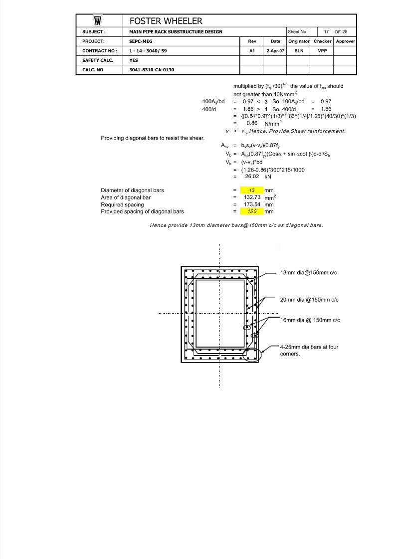
v > v c, Hence , Provide Shear re inforcement .Providing diagonal bars to resist the shear.
= bvs v(v-v c)/0.87f y
Vb = A sb (0.87f y)(Cos a + sin acot b)d-d'/S b
Vb = (v-v c)*bd= (1.26-0.86)*300*215/1000= kN
Diameter of diagonal bars = mm Area of diagonal bar = mm 2
Required spacing = mmProvided spacing of diagonal bars = mm
Hence provide 13mm diameter bars@150mm c/c as d iagonal bars .
13mm dia@150mm c/c
20mm dia @150mm c/c
16mm dia @ 150mm c/c
26.02
4-25mm dia bars at fourcorners.
0.86
A sv
0.97 0.971.86
SAFETY CALC. YES
1.86
PROJECT: SEPC-MEG
CALC. NO 3041-8310-CA-0130
Approver
CONTRACT NO : 1 - 14 - 3040/ 59 A1 2-Apr-07 SLN VPP
SUBJECT : MAIN PIPE RACK SUBSTRUCTURE DESIGN Sheet No : 17 28
FOSTER WHEELER
Originator Checker Rev Date
13 132.73173.54
15 0
8/10/2019 FW Pipe Rack Document
http://slidepdf.com/reader/full/fw-pipe-rack-document 17/38
OF
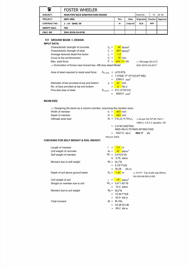
GROUND BEAM -1, DESIGN
INPUT DATA:Characteristic strength of concrete f cu = N/mm 2
Characteristic strength of steel f y = N/mm 2
Average factored dead+live factor gf =Cover to the reinforcement C = mmMax. axial force F = kN Ref page 26 of 27,
Summation of forces near braced bay -RB area staad Model 3041-8310-CA-0017
Area of steel required to resist axial force = gf F/0.87fy= 1.5*604.17*10^3/(0.87*460)= mm 2
Diameter of bar provided at top and bottom f = mm
No. of bars provided at top and bottom = No.sProvided area of steel = 6*3.14*32^2/4
= mm 2
BEAM SIZE:
Designing the beam as a column member, assuming the member sizes.Width of member b = mmDepth of member D = mmUltimate axial load N = 0.4f cu Ac+0.75A sc f y As per SS CP 65: Part 1:
1999 cl. 3.8.4.3, equation -38 =
= kN > kNHence Safe.
CHECKING FOR SELF WEIGHT & SOIL WEIGHT:
Length of member l = mUnit weight of concrete wc = kN/m 3
Self weight of member = 0.4*0.6*24= kN/m
Moment due to self weight M1 = W1l2/8= 5.76*7^2/8= kN.m
Depth of soil above ground beam Ds = m H.P.P - Top of pile cap-50mm,100.000-98.600-0.050
Unit weight of soil g = kN/m 3
Weight on member due to soil = 0.4*1.45*18= kN/m
Moment due to soil weight M2 = W2l2/8= 10.44*7 2̂/8= kN.m
Total moment M = M1+M2
= 35.28+63.95= kN.m
8.0
2264.5
6
A sc reqd.
7.0
60 0
A sc prov.
4825.5
63.9
CALC. NO 3041-8310-CA-0130
Approver Date
SAFETY CALC. YES
SUBJECT :
VPP2-Apr-07A1
MAIN PIPE RACK SUBSTRUCTURE DESIGN 18
Checker
SLN
PROJECT:
FOSTER WHEELER
SEPC-MEG Rev
28
Originator
Sheet No :
CONTRACT NO :
75
604.17
1 - 14 - 3040/ 59
40
46 0
1.5
W 1
5.76
35.28
32
24
40 0
5427.6
0.4*40*(400*600-
4825.49)+0.75*4825.49*460)/1000604.17
99.2
1.45
18
W 2
10.4

8/10/2019 FW Pipe Rack Document
http://slidepdf.com/reader/full/fw-pipe-rack-document 18/38
OF
Reinforcement required to resist moment:
Maximum design moment M = kN.mEffective depth of member d = D-c- f /2
= 600-75-32/2= mm
Breadth of beam considered b = mmk = As per SS CP 65: Part 1:
1999 cl. 3.4.4.4.= 99.23*10 6̂/(400*509^2*40)=
k' ( Redistribution not exceed 10%) =
k<k ' , Hence compress ion re in fo rcement i s no t requ ired .
Depth of lever arm z = (0.5+ (0.25-k/0.9))d,but not greater than 0.95d== mm= 0.95d= mm
Hence, z = mm Area of steel required A sb = M/0.87f yz
= 99.23*10 6̂/(0.87*460*483.55)= mm 2
Minimum % of steel = % As per SS CP 65: Part 1:
Minimum area of steel A sb min = 0.13*400*600/100 1999 Table 3.27 = mm 2
= mm 2
Hence, area of steel required = mm 2
Area of steel required from self weight & axial force = 2264.51+512.75= mm 2
Provided steel = mm 2
GB-1 is O.K.
(0.5+SQRT(0.25-0.024/0.9))*509
509
Originator Checker
4825.5
M/bd 2f cu
400
0.024
495.08
483.55483.55
0.156
2777.25
FOSTER WHEELER
SLN VPP
28
PROJECT: SEPC-MEG Rev Date Approver
SUBJECT : 19Sheet No :
CALC. NO 3041-8310-CA-0130
CONTRACT NO : 1 - 14 - 3040/ 59
SAFETY CALC. YES
512.75
512.75
zmax
0.13
312.00512.75
99.23
A1
MAIN PIPE RACK SUBSTRUCTURE DESIGN
2-Apr-07
H.P.P
G.B. P.C.
400
1000

8/10/2019 FW Pipe Rack Document
http://slidepdf.com/reader/full/fw-pipe-rack-document 19/38
SUBJECT Page No 20 OF 28PROJECT Rev. Date Originator Checker Approver
CONTRACT NO A1 2-Apr-2007 SLN VPP
SAFET CALCCALC NO
9.0 ANCHOR BOLT DESIGNFor anchor bolt design, unfactored loads are considered.
Critical Load casesNode L/C Fx Fy Fz300 113 3.136 407.346 76.986 Maximum F z
300 162 -0.988 -145.387 -48.864 Minimum F y
Case 1: Node no.300 load case 113 (Maximum Fz) Assume diameter of bolt = 24 mmTensile area of bolt = 361.91 mm 2
Number of anchor bolts = 4
Permissible shear stress of bolt = 80 N/mm 2 Cl. 15.2 of 3041-8310-SP-3003
Permissible tensile stress of Bolt =0.8*ft = 12 0 N/mm 2 for Grade 4.6 bolts.
Resultant Shear on Bolts = sqrt(F x2+F z
2)/No. of Bolts= 19.26 kN
Shear stress per bolt = 53.22 N/mm 2 < 80, O.K
Case 2: Node no.300 load case 162 (Minimum Fy) Assume diameter of bar = 24 mmTensile area of bolt = 361.91 mm 2
Number of anchor bolts = 4
Permissible shear stress of bolt = 80 N/mm 2 Cl. 15.2 of 3041-8310-SP-3003
Permissible tensile stress of bolt =0.8*ft = 120 N/mm 2 for Grade 4.6 bolts.
Resultant shear on bolts = sqrt(F x2+F z
2)/No. of Bolts12.22 kN
Shear stress per bolt = 33.76 N/mm 2 < 80, O.KTensile force per bolt = 36.35 kNTensile stress per bolt = 100.43 N/mm 2 < 120, O.KInteraction ratio = 1.26 <1.4, O.K
Anchor bolt projection P =
wheret =
b =n =d =
=the nuts.
== 86 mm
Use 4 No. Anchor Bolts, Type : A242/2
3041-8310-CA-0130
MAIN PIPE RACK SUBSTRUCTURE DESIGN
Thickness of base plate
0.5 Allowance for one washer and a small projection beyond
Thickness of grout
Number of boltsDiameter of bolt
25+25+(1+0.5)*24
FOSTER WHEELER
t+b+(n+0.5)d+ (50mm for bolts > 36mm dia
meter to allow for taper)
SEPC-MEG
1-14-3040/59
YES
8/10/2019 FW Pipe Rack Document
http://slidepdf.com/reader/full/fw-pipe-rack-document 20/38
Page No 21 OF 28
Rev. Date Originator Checker Approver
A1 02.04.07 SLN VPP
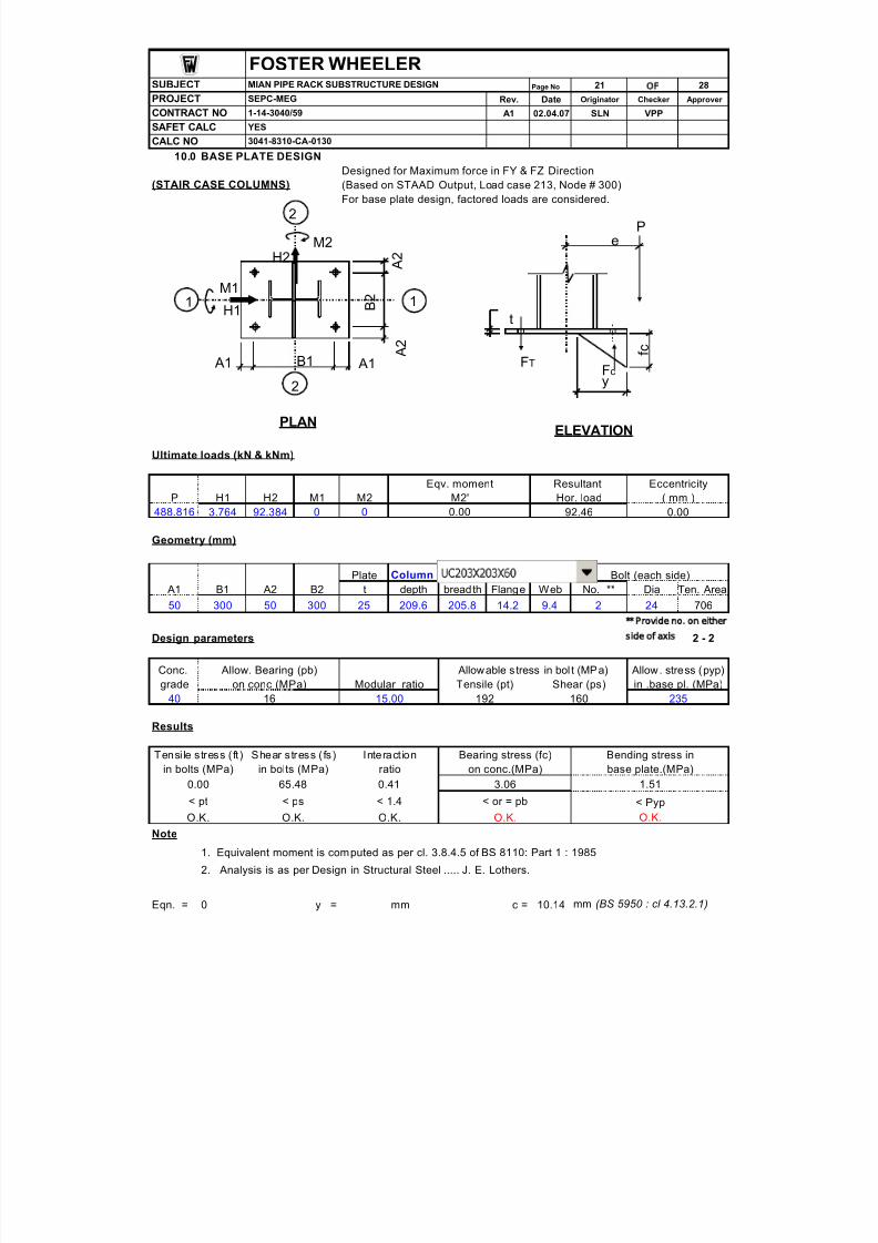
10.0 BASE PLATE DESIGNDesigned for Maximum force in FY & FZ Direction
(STAIR CASE COLUMNS) (Based on STAAD Output, Load case 213, Node # 300)
For base plate design, factored loads are considered.
Ultimate loads (kN & kNm)
Eqv. moment Resultant EccentricityP H1 H2 M1 M2 M2' Hor. load ( mm )
488.816 3.764 92.384 0 0 0.00 92.46 0.00
Geometry (mm)
Plate Column Bolt (each side) A1 B1 A2 B2 t depth bread th Flange Web No. ** Dia Ten. Area
50 300 50 300 25 209.6 205.8 14.2 9.4 2 24 706 Provide no. on either
Design parameters side of axis 2 - 2
Conc. Allow. Bearing (pb) Allowable s tress in bol t (MP a) Allow. stress (pyp)grade on conc (MPa) Modular ratio Tensile (pt) Shear (ps) in .base pl. (MPa)
40 16 15.00 192 160 235
Results
Tensi le s tress ( ft ) Shear s tress ( fs) Interact ion Bearing stress (fc) Bending stress inin bolts (MPa) in bolts (MPa) ratio on conc.(MPa) base plate.(MPa)
0.00 65.48 0.41 3.06 1.51
< pt < ps < 1.4 < or = pb < PypO.K. O.K. O.K. O.K. O.K.
Note
1. Equivalent moment is computed as per cl. 3.8.4.5 of BS 8110: Part 1 : 1985
2. Analysis is as per Design in Structural Steel ..... J. E. Lothers.
Eqn. = 0 y = mm c = 10.14 mm (BS 5950 : cl 4.13.2.1)
YES
3041-8310-CA-0130
SUBJECT
CONTRACT NOSAFET CALCCALC NO
1-14-3040/59
FOSTER WHEELERMIAN PIPE RACK SUBSTRUCTURE DESIGN
SEPC-MEGPROJECT
1H1
M11
2
H2M2
2
A 2
A 2
B 2
A1 A1B1
PLAN
P
t
FcFT
y
f c
e
ELEVATION

8/10/2019 FW Pipe Rack Document
http://slidepdf.com/reader/full/fw-pipe-rack-document 21/38
8/10/2019 FW Pipe Rack Document
http://slidepdf.com/reader/full/fw-pipe-rack-document 22/38
Page No 22 OF 28
Rev. Date Originator Checker Approver
A1 02.04.07 SLN VPP
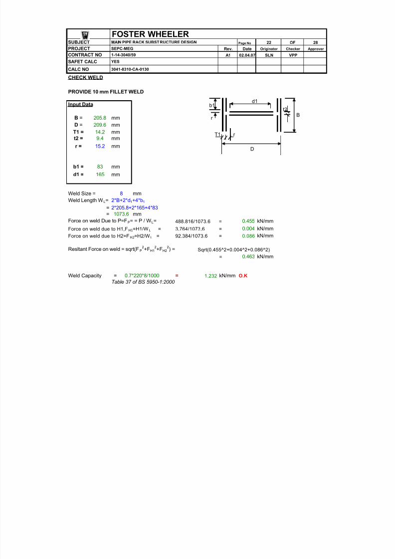
CHECK WELD
PROVIDE 10 mm FILLET WELD
Input Data
B = 205.8 mmD = 209.6 mmT1 = 14.2 mmt2 = 9.4 mm
r = 15.2 mm
b1 = 83 mm
d1 = 165 mm
Weld Size = 8 mmWeld Length W L= 2*B+2*d 1+4*b 1
= 2*205.8+2*165+4*83= 1073.6 mm
Force on weld Due to P=F P= = P / W L= 488.816/1073.6 = 0.455 kN/mm
Force on weld due to H1,F H1 =H1/W L = 3.764/1073.6 = 0.004 kN/mmForce on weld due to H2=F H2 =H2/W L = 92.384/1073.6 = 0.086 kN/mm
Resltant Force on weld = sqrt(F P2+F H1
2+F H22) = Sqrt(0.455^2+0.004^2+0.086^2)
= 0.463 kN/mm
Weld Capacity = 0.7*220*8/1000 = 1.232 kN/mm O.KTable 37 of BS 5950-1:2000
CALC NO 3041-8310-CA-0130
FOSTER WHEELER
CONTRACT NO 1-14-3040/59
SAFET CALC YES
SUBJECT MAIN PIPE RACK SUBSTRUCTURE DESIGN
PROJECT SEPC-MEG
B
D
T1 r
b1
r
t2
d1

8/10/2019 FW Pipe Rack Document
http://slidepdf.com/reader/full/fw-pipe-rack-document 23/38
OF
PLINTH DESIGNINPUT DATA:
Characteristic strength of concrete f cu = N/mm 2
Characteristic strength of steel f y = N/mm 2
Length of pedestal l = mmBreadth of pedestal b = mmHeight of pedestal H = mmUnit weight of concrete wc = kN/m 3
Clear cover to reinforcement c = mmDia. of longitudinal bar f = mmDia. of horizontal reinforcement f t = mm
LOADS ON PLINTH:Downward force Fy = kN Ref. Node No:300,L/C 253,
Lateral forces Fx = kN RA-1 area staad Model Fz = kN
MomentsMx = kN.mMz = kN.m
MOMENTS DUE TO ECCENTRICTY
Minimum eccentricity e = As per SS CP 65: Part 1:
1999, Cl. 3.8.2.4Momnet due to eccentricity Me = Fy*e
= 488.816*0.02= kN.m
DESIGN FORCES & MOMENTSSelf. Weight of plinth wp = l*b*H*wc
= 0.6*0.6*1*24= kN
Total Downward force P u = Fy+w p
= 488.82+8.64= kN
Moment about X - axis MX = Fz*H+Mx or M e Whichever is maximum
= 92.38*1+0= kN.m
Moment about Z - axis M = Fx*H+Mz or M e
= 9.78= kN.m
SLENDERNESS RATIO:Effective length of pedestal l ' = l-c-f /2
= 600-75-20/2= mm
Effective width of pedestal b' = b-c- f /2= 600-75-20/2
20 mm
9.78
515.00
Date
SAFETY CALC. YES
SUBJECT :
VPP2-Apr-07A1
MAIN PIPE RACK SUBSTRUCTURE DESIGN 23
Checker
SLN1 - 14 - 3040/ 59
FOSTER WHEELER
SEPC-MEG Rev
28
Originator
Sheet No :
CONTRACT NO :
Approver
40
46 0
PROJECT:
CALC. NO 3041-8310-CA-0130
11.0
10
75
20
60 0
60 0
1000
24
488.816
3.764
92.384
0
0
8.64
497.46
92.38
9.78
X
Z
l
b

8/10/2019 FW Pipe Rack Document
http://slidepdf.com/reader/full/fw-pipe-rack-document 24/38
= mm
OF
Slenderness ratio = l '/ b'= 515/515=
Bi- AXIAL MOMENT CHECK
Mx /l' M z /b', M x ' = M X + (l'/h')M Z Equation 40 Mx /l' <M z /b', M z ' = M Z + (b'/l')M X Equation 41
P/BLf cu = 497.46*10^3/(600*600*40)=
b = As per SS CP 65: Part 1:1999 Table. 3.24
MX/l' = 92.38/0.515= kN
MZ/b' = 9.78/0.515= kN
Mx' = kNmHence, ultimate design moment Mu = kNm
REINFORCEMENT :Longitudinal bars:
Mu/bl2 = N/mm 2
P u/bl = N/mm 2
b'/b = As per BS 8110-3 : 1985
From chart No: 37
Reinforcement required is very less, Hence provide minimum % of reinforcement.Minimum % of steel = As per SS CP 65: Part 1:
1999 Table. 3.27
Area of steel required = 0.4*600*600/100= mm 2
Diameter of bar provided f = mmNo. of bars required = No.SProvided No. of bars = No.s
Provided area of steel = mm 2
Hence Provid e 8 No.s of 20 dia. bars.Lateral Ties:
As per SS CP 65: Part 1:a. 1/4th of the dia. of longitudinal bar = mm 1999 cl. 3.12.7 b. 6mmDiameter of tie - bars, maximum of a & b = 6 mmProvided diameter of bar f t =
Spacing required for tie bars = 12 times longitunal bar.= mm
Provided spacing for ties = mm10 0
2513.3
5
10
120
20 4.58
8
0.86
0.4
1440.00
A sc
101.73101.73
0.47
1.38
515.00
1.00
0.035
FOSTER WHEELER SUBJECT : MAIN PIPE RACK SUBSTRUCTURE DESIGN Sheet No : 24 28
Approver
SLN VPP
PROJECT: SEPC-MEG Rev Date
A1 2-Apr-07
Originator Checker
CALC. NO 3041-8310-CA-0130
CONTRACT NO : 1 - 14 - 3040/ 59
SAFETY CALC. YES
179.39
18.98
0.956

8/10/2019 FW Pipe Rack Document
http://slidepdf.com/reader/full/fw-pipe-rack-document 25/38

8/10/2019 FW Pipe Rack Document
http://slidepdf.com/reader/full/fw-pipe-rack-document 26/38

8/10/2019 FW Pipe Rack Document
http://slidepdf.com/reader/full/fw-pipe-rack-document 27/38
OF
GROUND BEAM - 6, DESIGNINPUT DATA:
Characteristic strength of concrete f cu = N/mm 2
Characteristic strength of steel f y = N/mm 2
Cover to the reinforcement C = mmMax. axial force F = Ref. Node No: 300, L/C 11,
RA-1 area staad Model Area of steel required to resist axial force = 1.5F/0.87fy
= 1.5*76.987*10^3/(0.87*460)= mm 2
Diameter of bar provided at top and bottom f = mm
No. of bars provided at top and bottom = No.sProvided area of steel = 6*3.14*16^2/4
= mm 2
BEAM SIZE:
Designing the beam as a column member, assuming the member sizes.Width of member b = mmDepth of member D = mmUltimate axial load N = 0.4f cu Ac+0.75A sc f y As per SS CP 65: Part 1:
1999 cl. 3.8.4.3, equation -38 =
= kN > kNHence Safe.
CHECKING FOR SELF WEIGHT & SOIL WEIGHT:
Length of member l = mUnit weight of concrete wc = kN/m 3
Self weight of member = 0.3*0.4*24= kN/m
Moment to due to self weight M1 = W 1l2/8= 2.88*6^2/8= kN.m
Depth of soil above ground beam Ds = m 100.000-98.600 Unit weight of soil g = kN/m 3
weight on member due to soil = 0.3*1.45*18= kN/m
Moment due to soil weight M2 = W 2l2/8= 7.83*6^2/8= mm
Total moment M = M1+M2
= 12.96+35.24= kN.m
12.0
1.45
18 W 2
7.83
6.0
40 0
A sc prov.
48.2
40
46 0
75
W 1
16
24
A sc reqd.
FOSTER WHEELER
SEPC-MEG Rev
28
Originator
Sheet No :
CONTRACT NO : 1 - 14 - 3040/ 59
SUBJECT :
VPP2-Apr-07A1
MAIN PIPE RACK SUBSTRUCTURE DESIGN 26
Checker
SLN
PROJECT:
3041-8310-CA-0130
Approver Date
SAFETY CALC. YES
CALC. NO
2.88
12.96
35.2
76.987
288.56
6
1206.4
2316.9
0.4*40*(300*400-
1206.37)+0.75*1206.37*460)/1000
30 0
76.987

8/10/2019 FW Pipe Rack Document
http://slidepdf.com/reader/full/fw-pipe-rack-document 28/38
OF
Reinforcement required to resist moment:
Maximum design moment M = kN.mEffective depth of member d = D-c- f /2
= 400-75-16/2= mm
Breadth of wall considered b = mmk = As per SS CP 65: Part 1:
1999 cl. 3.4.4.4.= 48.20*10^6/(300*317^2*40)
=k' ( Redistribution not exceed 10%) =k<k' , Hence compress ion re inforcement is not requ ired.
Depth of lever arm z = (0.5+ (0.25-k/0.9))d,but not greater than 0.95d== mm= 0.95d= mm
Hence, z = mm Area of steel required A sb = M/0.87f yz
= 48.20*10^6/(0.87*460*301.15)
= mm 2
Minimum % of steel = % As per SS CP 65: Part 1:
Minimum area of steel A sb min = 0.13*300*400/100 1999 Table 3.27 = mm 2
= mm 2
Hence, area of steel required = mm 2
Area of steel required from self weight & axial force = 288.56+399.89= mm 2
Provided steel = mm 2
GB-6 is O.K.
MAIN PIPE RACK SUBSTRUCTURE DESIGN
2-Apr-07
399.89
zmax
0.13
156.00399.89
CALC. NO 3041-8310-CA-0130
399.89
48.20
SUBJECT :
CONTRACT NO : 1 - 14 - 3040/ 59
SAFETY CALC. YES
A1
PROJECT: SEPC-MEG Rev Date Originator Checker
SLN VPP
27Sheet No : 28
Approver
FOSTER WHEELER
301.15301.15
0.156
(0.5+SQRT(0.25-0.040/0.9))*317
317
688.451206.4
M/bd 2f cu
300
0.040
302.23
H.P.P
G.B.
400
100050
PLINTH

8/10/2019 FW Pipe Rack Document
http://slidepdf.com/reader/full/fw-pipe-rack-document 29/38
APPENDIX - A
POCKET DESIGN FOR ERECTION MOMENTS.
MAIN PIPE RACK SUBSTRUCTURE DESIGN
FOSTER WHEELER
SEPC-MEG Rev Originator
CONTRACT NO : 1 - 14 - 3040/ 59
SUBJECT :
PROJECT:
3041-8310-CA-0130
SAFETY CALC. YES
2-Apr-07A1
Approver Date Checker
SLN VPP
CALC. NO

8/10/2019 FW Pipe Rack Document
http://slidepdf.com/reader/full/fw-pipe-rack-document 30/38

8/10/2019 FW Pipe Rack Document
http://slidepdf.com/reader/full/fw-pipe-rack-document 31/38
OF
INPUT DATA:Characteristic strength of concrete f cu = N/mm 2
Characteristic strength of steel f y = N/mm 2
Pre cast column width Bc = mmPre cast column depth Dc = mmClearance at bottom C b = mmClearance at top C t = mmDepth of pocket H = mmWidth of pocket at top D = mmClear cover to the reinforcement c = mm
I) Checking of precast pocket for erection stage:i) Due to wind load: [Figure :1]
Column size = x mmWind pressure = kN/m 2
External building coefficient = 2 As per BS 6399-2:1997
Table 20
Height of column considered l = m
Wind load on the column w = 0.8*0.689*2= kN/m
Moment due to wind load on column = wl2/2= 1.10*12 2̂/2= kN.m
Hence, factored moment about Z-axis = 1.5*79.37= kN.m
Factored shear force due to long. wind load Fx = g*w*l= 1.5*1.10*12= kN
12
1.10Mw
79.37Mz
19.843
30 0
119.06
During erection stage precast columns will be free standing cantilever and will be subjected to windloads as shown in figure :1.
As shown in figure :3, column size is more along transverse direction(Z), hence wind load alonglongitudinal direction(X) is considered on the column.
500 800
0.689
C pe
80 0
50
10 0
1000
1 - 14 - 3040/ 59
40
46 0
50 0
75
PROJECT:
FOSTER WHEELER
SEPC-MEG Rev
A9
Originator
Sheet No :SUBJECT :
VPP2-Apr-07A1
DESIGN OF POCKET FOR P.C. COLUMN A1
Checker
SLN
Approver Date
CONTRACT NO :
3041-8310-CA-0130
SAFETY CALC. YES
CALC. NO
Wind load
Figure :1
1% of factored self.Wt. of beam
Main transverse
Figure :2
Figure :3
Longitudinal Direction - X
T r a n s v e r s e
D i r e c
t i o n - Z P.C. Column
8/10/2019 FW Pipe Rack Document
http://slidepdf.com/reader/full/fw-pipe-rack-document 32/38
OF
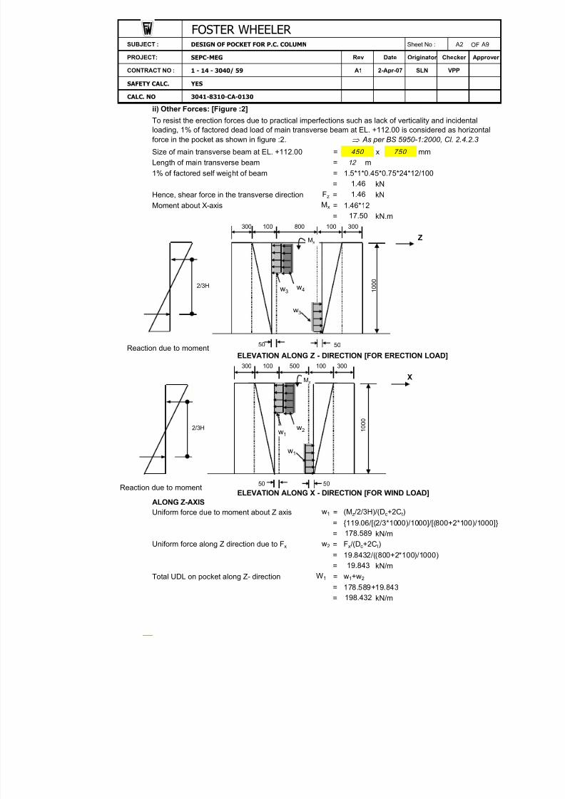
ii) Other Forces: [Figure :2]
Size of main transverse beam at EL. +112.00 = x mmLength of main transverse beam = m1% of factored self weight of beam = 1.5*1*0.45*0.75*24*12/100
= kNHence, shear force in the transverse direction F z = kNMoment about X-axis = 1.46*12
= kN.m
Z
50
ELEVATION ALONG Z - DIRECTION [FOR ERECTION LOAD]
X
50 50
ELEVATION ALONG X - DIRECTION [FOR WIND LOAD]ALONG Z-AXISUniform force due to moment about Z axis = (Mz/2/3H)/(D c+2C t)
= {119.06/[(2/3*1000)/1000]/[(800+2*100)/1000]}= kN/m
Uniform force along Z direction due to F x = Fx/(Dc+2C t)= 19.8432/((800+2*100)/1000)= kN/m
Total UDL on pocket along Z- direction = w1+w 2
= 178.589+19.843= kN/m
Mx
17.50
To resist the erection forces due to practical imperfections such as lack of verticality and incidental
loading, 1% of factored dead load of main transverse beam at EL. +112.00 is considered as horizontalforce in the pocket as shown in figure :2. As per BS 5950-1:2000, Cl. 2.4.2.3
CALC. NO 3041-8310-CA-0130
DESIGN OF POCKET FOR P.C. COLUMN
w2
W1
198.432
450 750
500 100 300
1 0 0 0
w1
300 100 800 100
50
300 100
CONTRACT NO : 1 - 14 - 3040/ 59
SAFETY CALC. YES
A1
178.589
A9
PROJECT: SEPC-MEG Rev Date Originator Checker Approver
SUBJECT : A2
SLN VPP
19.843
1.46
300
1 0 0 0
12
1.46
FOSTER WHEELER
2-Apr-07
Sheet No :
Mx
w3w4
w3
Mz
w2
w1
w1
2/3H
Reaction due to moment
Reaction due to moment
2/3H

8/10/2019 FW Pipe Rack Document
http://slidepdf.com/reader/full/fw-pipe-rack-document 33/38
OF
ALONG X-AXISUniform force due to moment about X-axis = (Mx/2/3H)/(B c+2C t)
= {17.50/[(2/3*1000)/1000]/[(500+2*100)/1000]}= kN/m
Uniform force along X direction due to F z = Fz/(Bc+2C t)= 1.46/((500+2*100)/1000)= kN/m
Total UDL on pocket along X- direction = w3+w 4
= 37.49+2.08= kN/m
BENDING MOMENT CALCULATIONS: with reference to the Reinforced Concrete Designer's hand book (Reynolds & Steedman) the bending
moment in the " beam" b/w the side walls can be assessed, treating the pocket as a Box culvert.
X- DIRECTION:
kN/m
Center to center distance B/W walls along l = Bc+C t+C t+D/2+D/2X- direction = 500+100+100+300/2+300/2
= mmCenter to center distance B/W walls along h = Dc+C t+C t+D/2+D/2Z- direction = 800+100+100+300/2+300/2
= mmk = (l/h)(h s /h w)3
= (1000/1300)*(300/300)^3=
k1 = k+1=
k3 = k+3=
k5 = 2k+3=
q 1 = W1(Dc+2C t)/h+D= 198.432*(800+2*100)/(1300+300)= kN/m
W2
39.57
198.432
1000
w4
w3
37.49
2.08
CONTRACT NO :
SAFETY CALC. YES
1 - 14 - 3040/ 59 A1 2-Apr-07
PROJECT: SEPC-MEG Rev Date Approver
SLN
Originator Checker
FOSTER WHEELER Sheet No : A3 A9
CALC. NO 3041-8310-CA-0130
VPP
SUBJECT : DESIGN OF POCKET FOR P.C. COLUMN
1300
0.77
1.77
3.77
4.54
124.02
A B
C D
X
Z
hw hw
h s
h
hs
l
q1

8/10/2019 FW Pipe Rack Document
http://slidepdf.com/reader/full/fw-pipe-rack-document 34/38
OF
Bending moment at B & D = q1h2k/12k 1k3
= 124.02*(1.3)̂ 2*0.77/(12*1.77*3.77)= kN.m
Bending moment at A & C = Mbd k5/k= 2.01*4.54/0.77= kN.m
Free span moment Mx = q1h2/8= 124.02*(1.3)̂ 2/8= kN.m
Z - DIRECTION:
kN/m
k = (h/l)(h w/h s )3
= (1300/1000)*(300/300)^3=
k1 = k+1=
k3 = k+3=
k5 ==
q 2 = W2(Bc+2C t)/h+D= (39.574*(500+2*100))/(1000+300)= kN/m
Bending moment at C & D = q2*l2*k/12*k1*k3
= 21.31*(1)̂ 2*1.30/(12*2.30*4.30)= kN.m
Bending moment at A & B == 0.23*5.60/1.30= kN.m
Free span moment = q2*l2/8= 21.31*(1) 2̂/8= kN.m
39.57
VPP
2.30
2k+3
Mz
Mab
2.66
Originator Date
SLN
1.01
Mcd k5/k
PROJECT:
FOSTER WHEELER SUBJECT : DESIGN OF POCKET FOR P.C. COLUMN Sheet No : A4 A9
Checker Approver
3041-8310-CA-0130
CONTRACT NO : 1 - 14 - 3040/ 59 A1 2-Apr-07
SAFETY CALC.
CALC. NO
1.3
2.01Mbd
Mca
11.89
0.23
SEPC-MEG Rev
YES
4.3
5.6
21.31Mcd
26.20
A B
C D
X
Z
hw hw
h s
h
h s
l
q2

8/10/2019 FW Pipe Rack Document
http://slidepdf.com/reader/full/fw-pipe-rack-document 35/38
OF
COMBINED BENDING MOMENTS ( X & Z DIRECTIONS):
1.Bending moment at A = Mca +Mab= 11.89+1.01= kN.m
2.Bending moment at B = Mbd +Mab
= 2.01+1.01= kN.m
3.Bending moment at C = Mca +Mcd
= 11.89+0.23= kN.m
4.Bending moment at D = Mbd +Mcd
== kN.m
5.Span moment mid span AB = Mz-(M A+MB)/2
= 2.66-(12.89+3.02)/2= kN.m
6.Span moment mid span AC = Mx-(M A+MC)/2= 26.20-(12.89+12.12)/2= kN.m
Maximum design moment M = kN.mEffective depth of wall d = D-c- f /2
= 300-75-20/2= mm
Breadth of wall considered b == 0.45*1000= mm
k = As per SS CP 65: Part 1:1999 cl. 3.4.4.4.
= 13.69*10 6̂/(450*215^2*40)=
k' ( Redistribution not exceed 10%) =
k<k ' , Hence compress ion re in fo rcement i s no t requ ired .
Depth of lever arm z = (0.5+ (0.25-k/0.9))d,but not greater than 0.95d== mm= 0.95d= mm
Hence, z = mm
Area of steel required A sb = M/0.87f yz= 13.69*10 6̂/(0.87*460*204.25)= mm 2
Minimum %age of steel = % As per SS CP 65: Part 1:
Minimum area of steel A sb min = 0.4*450*300/100 1999 Table 3.27 = mm 2
Area of steel required for 450mm width = mm 2
Hence, area of steel required per 'm' width = mm 2
VPP
0.016
CONTRACT NO : 1 - 14 - 3040/ 59
SAFETY CALC. YES
2-Apr-07 SLN
A9
PROJECT: SEPC-MEG Rev Date Originator Checker Approver
Sheet No : A5
CALC. NO
A1
1200
0.40
540.00540.00
SUBJECT : DESIGN OF POCKET FOR P.C. COLUMN
3041-8310-CA-0130
FOSTER WHEELER
167.52
12.89
MC
MD
M AB
M A
MB
M/bd 2f cu
0.45H
450
3.02
-5.29
2.01+0.2
12.12
2.25
210.99
204.25204.25
0.156
(0.5+SQRT(0.25-0.016/0.9))*215
M AC
13.6913.69
215
zmax

8/10/2019 FW Pipe Rack Document
http://slidepdf.com/reader/full/fw-pipe-rack-document 36/38
OF
DIRECT TENSION: Since the beam is spanning between the side walls, the UDL on the beam puts tension in the side
walls.
Tension force F = Max. of forces in X & Z direction.Tension force in X- direction Fx = W1*(Dc+2C t)/2
= 198.43*(800+2*100)/(2*1000)= kN
Tension force in Z- direction F z = W2*(Bc+2C t)/2= 39.57*(500+2*100)/(2*1000)= kN
Maximum tension force F = kN Area of tension reinforcement A st = F/0.87f y
= 99.22*10^3/(0.87*460) Area of steel required for 450mm width = mm 2
Hence, area of steel required per 'm' width =mm
2
Horizontal reinforcement required per face A s = A sb + 0.5 A st
= 1200+0.5*550.92= mm 2
Diameter of bar f = mmRequired spacing = mmProvided spacing = mm
Area of steel provided = mm 2
Prov ide 20mm d ia @ 200mm c/c as ho r izon tal re in f . on b o th faces .
SIDE WALLS:Walls AB & CD
Force in the walls due to UDL & moment F1 = W1*(Dc+2C t)/2= 198.43*(800+2*100)/(2*1000)= kN
Force due to moment F2 = w1*(Dc+2C t)/2= 178.59*(800+2*100)/(2*1000)= kN
Moment in the walls due to F 1 & F 2 M1 = F1*(H-0.45H/2)-(F 2*0.45H/2)=
= kN.mEffective depth of wall d 1 = Bc+2*C t+2D-c- f -f /2
= (500+2*100+2*300)-75-20-20/2= mm
89.29
99.22*((1000-(0.45*1000)/2)/1000)-89.2944*(0.45*1000/2)/1000
A1 2-Apr-07
SAFETY CALC. YES
CALC. NO 3041-8310-CA-0130
99.22
A9
PROJECT: SEPC-MEG Rev Date Originator Checker Approver
1570.820 0
A s prov
A6SUBJECT : DESIGN OF POCKET FOR P.C. COLUMN
CONTRACT NO : 1 - 14 - 3040/ 59 SLN VPP
1195.00
FOSTER WHEELER
99.22
56.80
Sheet No :
550.92
1475.5
212.9220
247.92
13.85
99.22
H - 0 . 4
5 H / 2
F1
F2

8/10/2019 FW Pipe Rack Document
http://slidepdf.com/reader/full/fw-pipe-rack-document 37/38

8/10/2019 FW Pipe Rack Document
http://slidepdf.com/reader/full/fw-pipe-rack-document 38/38
OF
k = M2/bd 22f cu As per SS CP 65: Part 1:
1999 cl. 3.4.4.4.
= 7.78*10^6/(300*1495^2*40)=
k' ( Redistribution not exceed 10%) =k<k ' , Hence compress ion re in fo rcement i s no t requ ired .
Depth of lever arm z = (0.5+ (0.25-k/0.9))d,but not greater than 0.95d= (0.5+SQRT(0.25-0.000/0.9))*1495= mm
zmax = 0.95d= 0.95*1495= mm
Hence, z = mm Area of steel required = M2/0.87f yz
= 7.78*10^6/(0.87*460*1420.25)= mm 2
Minimum %age of steel = %Minimum area of steel = 0.4*D*Dc+2*Ct+2D/100
= 0.4*300*(800+2*100+2*300)/100= mm 2
Diameter of bar f = mmNo. of bars required =No. of bars provided =
Prov ide 4 -25d ia , ver t ical bars a t co rners .DISTRIBUTION STEEL: As per SS CP 65: Part 1:
1999 cl. 3.4.4.4.Distribution of steel = 0.25% of concrete area
= 0.25*300*1000/100
= mm2
Diameter of bar provided fs = mmRequired spacing = mmProvided spacing = mm
Prov ide 16 d ia @ 200mm c/c as ver t ical re in fo rcement o n bo th faces .CHECK FOR SHEAR:
Considering shear in upper zone of pocket with following dimensions.Breadth of section considered b = Depth of wall section is considered.
= mmDepth of section D = mm Top width of wall is considered.
Effective depth of section d = D-c- f /2= 300-75-20/2= mm
Maximum reaction V = Max. of F 1 & F 3 As per SS CP 65: Part 1:= kN 1999 cl. 3.4.5.2
Design shear stress v = V/bd= 99.22*10^3/(1000*215)= N/mm 2
Design concrete shear stress vc = 0.84{100A s /bd}1/3 (400/d) 1/4 /gm
100A s /bd should not be greater than 3.400/d should not be taken as less than 1
CALC. NO 3041-8310-CA-0130
Approver
CONTRACT NO : 1 - 14 - 3040/ 59 A1 2-Apr-07 SLN VPP
SUBJECT : A8 A9
1494.5
1420.3
FOSTER WHEELER DESIGN OF POCKET FOR P.C. COLUMN Sheet No :
PROJECT: SEPC-MEG Rev
SAFETY CALC. YES
215
4
13.6920.40
1920.00
1420.3
1000
16
268.08
750
3.91
300
99.22
0.46
A smin
25
20 0
A s2
Date Originator
0.0000.156
Checker