
Fuse holder terminal blocks - Entrelec Sales · 135 0,5-4 mm² 22-12 AWG 24-12 AWG 0,5-4 mm² 22-12...
44
133 NA1FC7T Fuse holder terminal blocks 001222
Transcript of Fuse holder terminal blocks - Entrelec Sales · 135 0,5-4 mm² 22-12 AWG 24-12 AWG 0,5-4 mm² 22-12...
133
NA1FC7T
Fuse holderterminal blocks
001222
134
0,5-4 mm² 22-12 AWG 24-12 AWG0,5-4 mm² 22-12 AWG 24-12 AWG
630 V (1) 600 V (1) 250 V8 kV
3
6,3 A 10 A 10 A
4 mm² / A4 12 AWG 12 AWG
0,5-4 mm² 22-12 AWG 24-12 AWG0,5-4 mm² 22-12 AWG 24-12 AWG
400 V (1) 600 V (1) 250 V4 kV
3
6,3 A 6,3 A 10 A
4 mm² / A4 12 AWG 12 AWG
IEC UL CSANFC DIN
IEC UL CSANFC DIN
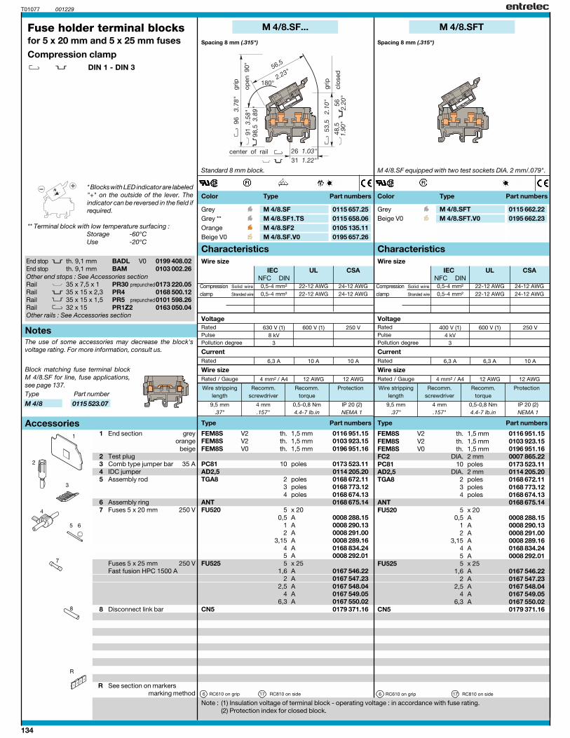
M 4/8.SF...
T01077 001229
9,5 mm 4 mm 0,5-0,8 Nm IP 20 (2).37" .157" 4.4-7 Ib.in NEMA 1
FEM8S V2 1,5 mm 0116 951.15FEM8S V2 1,5 mm 0103 923.15FEM8S V0 1,5 mm 0196 951.16
PC81 10 0173 523.11AD2,5 0114 205.20TGA8 2 0168 672.11
3 0168 773.124 0168 674.13
ANT 0168 675.14FU520 5 x 20
0,5 A 0008 288.151 A 0008 290.132 A 0008 291.00
3,15 A 0008 289.164 A 0168 834.245 A 0008 292.01
FU525 5 x 25 1,6 A 0167 546.22
2 A 0167 547.23 2,5 A 0167 548.04
4 A 0167 549.05 6,3 A 0167 550.02
CN5 0179 371.16
6 17
M 4/8.SFT
M 4/8.SFT 0115 662.22M 4/8.SFT.V0 0195 662.23
9,5 mm 4 mm 0,5-0,8 Nm IP 20 (2).37" .157" 4.4-7 Ib.in NEMA 1
M 4/8.SF 0115 657.25M 4/8.SF1.TS 0115 658.06M 4/8.SF2 0105 135.11M 4/8.SF.V0 0195 657.26
1
3
FEM8S V2 1,5 mm 0116 951.15FEM8S V2 1,5 mm 0103 923.15FEM8S V0 1,5 mm 0196 951.16FC2 2 mm 0007 865.22PC81 10 0173 523.11AD2,5 2 mm 0114 205.20TGA8 2 0168 672.11
3 0168 773.124 0168 674.13
ANT 0168 675.14FU520 5 x 20
0,5 A 0008 288.151 A 0008 290.132 A 0008 291.00
3,15 A 0008 289.164 A 0168 834.245 A 0008 292.01
FU525 5 x 25 1,6 A 0167 546.22
2 A 0167 547.23 2,5 A 0167 548.04
4 A 0167 549.05 6,3 A 0167 550.02
CN5 0179 371.16
6 17
2
4
65
R
8
7
M 4/8 0115 523.07
BADL V0 0199 408.02BAM 0103 002.26
35 x 7,5 x 135 x 15 x 2,3 PR4 0168 500.1235 x 15 x 1,532 x 15 PR1Z2 0163 050.04
End stop th. 9,1 mmEnd stop th. 9,1 mmOther end stops : See Accessories sectionRail PR30 prepunched0173 220.05RailRail PR5 prepunched0101 598.26RailOther rails : See Accessories section
Color Type Part numbers Color Type Part numbers
Fuse holder terminal blocksfor 5 x 20 mm and 5 x 25 mm fusesCompression clamp
DIN 1 - DIN 3
Spacing 8 mm (.315")Spacing 8 mm (.315")
1 End section greyorange
beige2 Test plug3 Comb type jumper bar 35 A4 IDC jumper5 Assembly rod
6 Assembly ring7 Fuses 5 x 20 mm 250 V
Fuses 5 x 25 mm 250 VFast fusion HPC 1500 A
8 Disconnect link bar
R See section on markersmarking method
Standard 8 mm block.
Note : (1) Insulation voltage of terminal block - operating voltage : in accordance with fuse rating.(2) Protection index for closed block.
M 4/8.SF equipped with two test sockets DIA. 2 mm/.079".
* Blocks with LED indicator are labeled"+" on the outside of the lever. Theindicator can be reversed in the field ifrequired.
** Terminal block with low temperature surfacing :Storage -60°CUse -20°C
th.th.th.
poles
polespolespoles
RC610 on grip RC810 on side
GreyBeige V0
GreyGrey **OrangeBeige V0
th.th.th.
DIA.poles
DIA.polespolespoles
RC610 on grip RC810 on side
Block matching fuse terminal blockM 4/8.SF for line, fuse applications,see page 137.Type Part number
Characteristics Characteristics
Type Part numbers
Rated
Rated / Gauge
Wire size
Current
Wire size
Notes
Type Part numbers
Rated
Rated / Gauge
Wire size
Current
Wire size
Accessories
Wire stripping Recomm. Recomm. Protectionlength screwdriver torque
Wire stripping Recomm. Recomm. Protectionlength screwdriver torque
Compression Solid wire
clamp Stranded wire
RatedPulsePollution degree
VoltageRatedPulsePollution degree
Compression Solid wire
clamp Stranded wire
Voltage
The use of some accessories may decrease the block'svoltage rating. For more information, consult us.

135
0,5-4 mm² 22-12 AWG 24-12 AWG
0,5-4 mm² 22-12 AWG 24-12 AWG
630 V 600 V 250 V8 kV
3
6,3 A 10 A 10 A
4 mm² / A4 12 AWG 12 AWG
0,5-4 mm² 22-12 AWG 24-12 AWG
0,5-4 mm² 22-12 AWG 24-12 AWG
400 V (1) 600 V (1) 250 V4 kV
3
6,3 A 10 A 10 A
4 mm² / A4 12 AWG 12 AWG
0,5-4 mm² 22-12 AWG 24-12 AWG0,5-4 mm² 22-12 AWG 24-12 AWG
400 V (1) 600 V (1) 250 V4 kV
3
6,3 A 10 A 10 A
4 mm² / A4 12 AWG 12 AWG
IEC UL CSANFC DIN
IEC UL CSANFC DIN
IEC UL CSANFC DIN
M 4/8.SF...T...
T01078 001229
9,5 mm 4 mm 0,5-0,8 Nm IP 20 (2).374" .157" 4.4-7 Ib.in NEMA 1
FEM8S V2 1,5 mm 0116 951.15FEM8S V2 1,5 mm 0103 923.15FEM8S V0 1,5 mm 0196 951.16FC2 2 mm 0007 865.22PC81 35 A 10 0173 523.11AD2,5 24 A 0114 205.20TGA8 2 0168 672.11
3 0168 773.124 0168 674.13
ANT 0168 675.14FU520 5 x 20
0,5 A 0008 288.151 A 0008 290.132 A 0008 291.00
3,15 A 0008 289.164 A 0168 834.245 A 0008 292.01
FU525 5 x 25 1,6 A 0167 546.22
2 A 0167 547.23 2,5 A 0167 548.04
4 A 0167 549.05 6,3 A 0167 550.02
6 17
M 4/8.SN...
M 4/8.SN1 0115 660.04M 4/8.SN2 0105 136.12M 4/8.SN1.V0 0195 660.05
9,5 mm 4 mm 0,5-0,8 Nm IP 20 (2).374" .157" 4.4-7 Ib.in NEMA 1
M 4/8.SFLT 0115 667.27M 4/8.SFDT 0115 665.25M 4/8.SFDT1 0115 666.26
M 4/8.SFL 0115 661.21M 4/8.SFD 0115 663.23M 4/8.SFD1 0115 664.24M 4/8.SFD2 0115 653.21
9,5 mm 4 mm 0,5-0,8 Nm IP 20 (2).374" .157" 4.4-7 Ib.in NEMA 1
FEM8S V2 1,5 mm 0116 951.15FEM8S V2 1,5 mm 0103 923.15FEM8S V0 1,5 mm 0196 951.16
PC81 35 A 10 0173 523.11AD2,5 24 A 0114 205.20TGA8 2 0168 672.11
3 0168 773.124 0168 674.13
ANT 0168 675.14FU520 5 x 20
0,5 A 0008 288.151 A 0008 290.132 A 0008 291.00
3,15 A 0008 289.164 A 0168 834.245 A 0008 292.01
FU525 5 x 25 1,6 A 0167 546.22
2 A 0167 547.23 2,5 A 0167 548.04
4 A 0167 549.05 6,3 A 0167 550.02
6 17
M 4/8.SF...
FEM8S V2 1,5 mm 0116 951.15FEM8S V2 1,5 mm 0103 923.15FEM8S V0 1,5 mm 0196 951.16
PC81 35 A 10 0173 523.11AD2,5 24 A 0114 205.20TGA8 2 0168 672.11
3 0168 773.124 0168 674.13
ANT 0168 675.14
6 17
CharacteristicsWire size
Color Type Part numbers
CharacteristicsWire size
Color Type Part numbers
Compression Solid wire
clamp Stranded wire
Compression Solid wire
clamp Stranded wire
Characteristics
Color Type Part numbers
Compression Solid wire
clamp Stranded wire
Wire size
M 4/8.SF with disconnect link bar locked on grey grip.
Spacing 8 mm (.315") Spacing 8 mm (.315") Spacing 8 mm (.315")
Note : (3) Blown fuse indicator : neon lamp 110-230 V. Leakage current with neon lamp : < 0,5 mA (110 V) / < 0,7 mA (230 V).(4) Leakage current with LED 24 or 48 V : < 4,5 mA. (5) Block delivered with - on open side.
M 4/8.SF with blown fuse indicator. Grey body.M 4/8.SF with blown fuse indicator equipped with 2 testsockets DIA. 2 mm/.079". Grey body.
th.th.th.
DIA.poles
polespolespoles
RC610 on grip RC810 on side
GreyOrangeBeige V0
th.th.th.
poles
polespolespoles
RC610 on grip RC810 on side
Neon lamp(3)Diode LED 24 V* (4)Diode LED 48 V* (4)
Neon lamp(3)Diode LED 24 V* (4)Diode LED 48 V* (4)Diode LED 48 V (4)(5)
th.th.th.
poles
polespolespoles
RC610 on grip RC810 on side
Type Part numbers
Rated
Rated / Gauge
Wire size
Current
Wire stripping Recomm. Recomm. Protectionlength screwdriver torque
RatedPulsePollution degree
Voltage
Type Part numbers
Rated
Rated / Gauge
Wire size
Current
Wire stripping Recomm. Recomm. Protectionlength screwdriver torque
RatedPulsePollution degree
Voltage
Type Part numbers
Rated
Rated / Gauge
Wire size
Current
Wire stripping Recomm. Recomm. Protectionlength screwdriver torque
RatedPulsePollution degree
Voltage

136
0,5-4 mm² 22-12 AWG 24-12 AWG0,5-4 mm² 22-12 AWG 24-12 AWG
630 V (1) 600 V (1) 250 V8 kV
3
6,3 A 10 A 10 A
4 mm² / A4 12 AWG 12 AWG
0,5-4 mm² 22-12 AWG 24-12 AWG0,5-4 mm² 22-12 AWG 24-12 AWG
400 V (1) 600 V (1) 250 V4 kV
3
6,3 A 10 A 10 A
4 mm² / A4 12 AWG 12 AWG
IEC UL CSANFC DIN
IEC UL CSANFC DIN
M 4/8.SN
T01079 001229
9,5 mm 4 mm 0,5-0,8 Nm IP 20 (2).37" .157" 4.4-7 Ib.in NEMA 1
FEM8S V2 1,5 mm 0116 951.15FEM8S V2 1,5 mm 0103 923.15FEM8S V0 1,5 mm 0196 951.16
PC81 35 A 10 0173 523.11AD2,5 24 A 0114 205.20TGA8 2 0168 672.11
3 0168 773.124 0168 674.13
ANT 0168 675.14
6 17
M 4/8.SNT
9,5 mm 4 mm 0,5-0,8 Nm IP 20 (2).37" .157" 4.4-7 Ib.in NEMA 1
M 4/8.SN 0115 659.07M 4/8.SN.V0 0195 659.00
1 FEM8S V2 1,5 mm 0116 951.15FEM8S V2 1,5 mm 0103 923.15FEM8S V0 1,5 mm 0196 951.16FC2 2 mm 0007 865.22 PC81 35 A 10 0173 523.11AD2,5 24 A 0114 205.20TGA8 2 0168 672.11
3 0168 773.124 0168 674.13
ANT 0168 675.14
6 17
2
R
5 6
4
3
M 4/8 0115 523.07
BADL V0 0199 408.02BAM 0103 002.26
35 x 7,5 x 135 x 15 x 2,3 PR4 0168 500.1235 x 15 x 1,532 x 15 PR1Z2 0163 050.04
M 4/8.SNT 0115 668.00M 4/8.SNT.V0 0195 668.01
End stop th. 9,1 mmEnd stop th. 9,1 mmOther end stops : See Accessories sectionRail PR30 prepunched0173 220.05RailRail PR5 prepunched0101 598.26RailOther rails : See Accessories section
Characteristics
Color Type Part numbers
Characteristics
Color Type Part numbers
Fuse holder terminal blocksfor 5 x 20 mm and 5 x 25 mm fusesCompression clamp
DIN 1 - DIN 3
Spacing 8 mm (.315")Spacing 8 mm (.315")
1 End section greyorange
beige2 Test plug3 Comb-type jumper bar 35 A4 IDC jumper5 Assembly rod
6 Assembly ring
R See section on markersmarking method
Note : (1) Insulation voltage of terminal block - operating voltage : in accordance with fuse rating.(2) Protection index given for closed block.
M 4/8.SF with disconnect link bar locked on blue grip.M 4/8.SF with disconnect link bar locked on blue grip,equipped with 2 test sockets DIA. 2 mm/.079".
th.th.th.
poles
polespolespoles
RC610 on lever RC810 on side
th.th.th.
DIA.poles
polespolespoles
RC610 on lever RC810 on side
Grey body/Blue gripBeige body/Blue V0 grip
Grey body/Blue gripBeige body/Blue V0 grip
Type Part numbers
Rated
Rated / Gauge
Wire size
Current
Wire size
Notes
Type Part numbers
Rated
Rated / Gauge
Wire size
Current
Wire size
Accessories
Wire stripping Recomm. Recomm. Protectionlength screwdriver torque
Wire stripping Recomm. Recomm. Protectionlength screwdriver torque
Compression Solid wire
clamp Stranded wire
RatedPulsePollution degree
VoltageRatedPulsePollution degree
Compression Solid wire
clamp Stranded wire
Voltage
The use of some accessories may decrease the block'svoltage rating. For more information, consult us.
Block matching fuse terminal blockM 4/8.SF for line, fuse applications,see page 137.Type Part number

137
NFC DIN UL CSA
M 4/8
T01004 001229
M 4/8 0115 523.07
0,2-4 mm² 22-12 AWG0,22-4 mm² 22-12 AWG
500 V Gr.C 600 V
26 A 15 A
4 mm² / A4 12 AWG
9,5 mm 4 mm 0,5-0,8 Nm IP 20.37" .16" 4.4-7.1 lb.in NEMA 1
FEM8S 1,5 mm 0116 951.15SCFCV3 3,0 mm 0116 796.12SCFCV3 V0 (1) V0 3,0 mm 0196 796.13CPV3 0176 817.13AL2 2,0 mm 0163 070.00AL3 3,0 mm 0163 261.00FC2 2 mm 0007 865.26PC81 10 0173 523.11AD2,5 0114 205.20
11
R
1
2
3
4
5
6
7
BADL V0 0199 408.02BAM 0103 002.26
35 x 7,5 x 135 x 15 x 2,3 PR4 0168 500.1235 x 15 x 1,532 x 15 x 1,5 PR1Z2 0163 050.04
End stop th. 9 mmEnd stop th. 9,1 mmRail PR30 prepunched0173 220.05RailRail PR5 prepunched0101 598.26RailOther end stops and rails : See Accessories section
Compression Solid wire
clamp Stranded wire
Characteristics
Type Part numbers
RatedPulsePollution degree
Rated
Rated / Gauge
Wire size
Current
Voltage
Wire size
Color Type Part number
Wire stripping Recomm. Recomm. Protectionlength screwdriver torque
Notes
Accessories
Standard terminal blocksCompression clamp
DIN 1 - 3
Spacing 8 mm (.315")
Note : (1) End sections and circuit separators snapped on rails.
Grey
th.th.th.
(for SCFCV3...)DIA.DIA.DIA.
poles
1 End section grey2 Separator end section grey
beige3 Protective cover4 Test socket
5 Test plug6 Comb type jumper bar 35 A7 IDC jumper
R See section on markersmarking method
The use of some accessories may decrease the block'svoltage rating. For more information, consult us.
Terminal block compatible with fuse block M 4/8.SF
Note: For terminal block withmatching profile to fuse blockM 4/8.SF, use M 4/8 shown here.

138
0,5-4 mm² 24-12 AWG 24-12 AWG0,5-4 mm² 24-12 AWG 24-12 AWG
630 V (7) 300 V (1) 250 V8 kV
3
6,3 A 10 A 10 A
4 mm² / A4 12 AWG 12 AWG
0,5-4 mm² 24-12 AWG 24-12 AWG0,5-4 mm² 24-12 AWG 24-12 AWG
500 V (7) 300 V (1) 250 V6 kV
3
6,3 A 10 A 10 A
4 mm² / A4 12 AWG 12 AWG
IEC UL CSANFC DIN
IEC UL CSANFC DIN
T01091 001229
M 4/8.D2.SF
9,5 mm 4 mm 0,5-0,8 Nm IP 20.37" .16" 4.4-7 Ib.in
FEM8D2S (V2) 0116 913.07FEM8D2S (V0) 0196 913.00AL2 (1) 2 mm 0163 043.21AL3 (1) 3 mm 0163 261.00AL4 (1) 4 mm 0163 262.01FC2 (3) 2 mm 0007 865.26FC4 (4) 4 mm 0167 860.01BJM8 (1) 41 A 0168 520.05BJM8 (1) 41 A 0168 521.22BJM8 (1) 41 A 0168 522.23BJM8 (1) 41 A 0168 523.24BJM8 (1) 41 A 0168 974.00EL6 35 A 0173 627.21PC81 35 A 10 0173 523.11AD2,5 24 A 0114 205.20TGA8 2 0168 672.11
3 0168 673.124 0168 674.13
ANT 0168 675.14FU520 0,5 A 0008 288.15
1 A 0008 290.132 A 0008 291.00
3,15 A 0008 289.165 A 0008 292.01
FU525 1,6 A 0167 546.22 2 A 0167 547.23
2,5 A 0167 548.044 A 0167 549.05
6,3 A 0167 550.02CN5 0168 804.07CBD2S 0178 408.14
6 17
M 4/8.D2.SF...
M 4/8.D2.SFL 0115 646.22M 4/8.D2.SFD 0115 647.23M 4/8.D2.SFD1 0115 648.04
9,5 mm 4 mm 0,5-0,8 Nm IP 20.37" .16" 4.4-7 Ib.in
M 4/8.D2.SF 0115 604.21M 4/8.D2.SF.V0 0195 604.22
FEM8D2S 0116 913.07
AL2 (1) 2 mm 0163 043.21AL3 (1) 3 mm 0163 261.00AL4 (1) 4 mm 0163 262.01FC2 (3) 2 mm 0007 865.26FC4 (4) 4 mm 0167 860.01BJM8 (1) 41 A 0168 520.05BJM8 (1) 41 A 0168 521.22BJM8 (1) 41 A 0168 522.23BJM8 (1) 41 A 0168 523.24BJM8 (1) 41 A 0168 974.00EL6 35 A 0173 627.21PC81 35 A 10 0173 523.11AD2,5 24 A 0114 205.20TGA8 2 0168 672.11
3 0168 673.124 0168 674.13
ANT 0168 675.14FU520 0,5 A 0008 288.15
1 A 0008 290.132 A 0008 291.00
3,15 A 0008 289.165 A 0008 292.01
FU525 1,6 A 0167 546.22 2 A 0167 547.23
2,5 A 0167 548.044 A 0167 549.05
6,3 A 0167 550.02
CBD2S 0178 408.14
6 17
1
32
45
8, 9
10
R
11
12
7
6
BAMH 0114 836.00
35 x 7,5 x 135 x 15 x 2,3 PR4 0168 500.1235 x 15 x 1,532 x 15 PR1Z2 0163 050.04
End stop th. 9,1 mmOther end stops : See Accessories sectionRail PR30 prepunched0173 220.05RailRail PR5 prepunched0101 598.26RailOther rails : See Accessories section
Color Type Part numbers Color Type Part numbers
Spacing 8 mm (.315")Spacing 8 mm (.315")
Standard block. M 4/8.D2.SF with blown fuse indicator. Grey body.
Fuse holder terminal blocksDouble-deckfor 5 x 20 and 5 x 25 mm fusesCompression clamp
DIN 1 - DIN 3
* Blocks with LED indicator are labeled"+" on the outside of the lever. Theindicator can be reversed in the field ifrequired.
1 End section grey
2 Test socket
3 Test plug
4 Assembledjumper bar(without IP 20 protection)
5 Connector plate6 Comb-type jumper bar7 IDC jumper8 Assembly rod
9 Assembly ring10 Fuse 5 x 20 mm 250 V
Fuse 5 x 25 mm 250 VFast acting HPC 1500 A
11 Disconnect link bar12 Shield connector
R See section on markersmarking method
Note : (1) Only for lower deck. (2) Only for upper connection. Use of these accessories requires the user to cut out the partition. (3) For block equipped with test socket AL2.(4) For block equipped with test socket AL4. (5) Leakage current with neon lamp : < 0,5 mA (110 VAC), < 0,7 mA (230 VAC). (6) Leakage current with LED 24 or 48 VDC < 4,5 mA.(7) Insulation voltage of terminal block - operating voltage : in accordance with fuse rating.
DIA.DIA.DIA.DIA.DIA.
poles
polespolespoles
RC 610 on grip RC 810 on side
Neon lamp110-230 V (5)LED 24 V (6)LED 48 V (6)
GreyBeige V0
DIA.DIA.DIA.DIA.DIA.
poles
polespolespoles
RC 610 on grip RC 810 on side
Characteristics Characteristics
Type Part numbers
Rated
Rated / Gauge
Wire size
Current
Wire size
Notes
Type Part numbers
Rated
Rated / Gauge
Wire size
Current
Wire size
Accessories
Wire stripping Recomm. Recomm. Protectionlength screwdriver torque
Wire stripping Recomm. Recomm. Protectionlength screwdriver torque
Compression Solid wire
clamp Stranded wire
RatedPulsePollution degree
VoltageRatedPulsePollution degree
Compression Solid wire
clamp Stranded wire
Voltage
The use of some accessories may decrease the block'svoltage rating. For more information, consult us.

139
0,5-4 mm² 24-12 AWG 24-12 AWG0,5-4 mm² 24-12 AWG 24-12 AWG
500 V (7) 300 V (7) 250 V6 kV
3
6,3 A 10 A 10 A
4 mm² / A4 12 AWG 12 AWG
IEC UL CSANFC DIN
T01108 001229
M 4/8.D2.SF...
9,5 mm 4 mm 0,5-0,8 Nm IP 20.374" .157" 4.4-7 Ib.in
FEM8D2S 0116 913.07AL2 (1) 2 mm 0163 043.21AL3 (1) 3 mm 0163 261.00AL4 (1) 4 mm 0163 262.01FC2 (3) 2 mm 0007 865.26FC4 (4) 4 mm 0167 860.01BJM8 (1) 41 A 0168 520.05BJM8 (1) 41 A 0168 521.22BJM8 (1) 41 A 0168 522.23BJM8 (1) 41 A 0168 523.24BJM8 (1) 41 A 0168 974.00EL6 35 A 0173 627.21PC81 35 A 10 0173 523.11TGA8 2 0168 672.11
3 0168 673.124 0168 674.13
ANT 0168 675.14FU520 0,5 A 0008 288.15
1 A 0008 290.132 A 0008 291.00
3,15 A 0008 289.165 A 0008 292.01
FU525 1,6 A 0167 546.22 2 A 0167 547.23
2,5 A 0167 548.044 A 0167 549.05
6,3 A 0167 550.02CN5 0168 804.07CBD2S 0178 408.14BJS8 (2) 41 A 20 0174 789.05EV6 0168 604.16VJS11 (2) 0163 394.26
6 17
1
32
45
7, 8
9
10
11
12, 13
R
6
M 4/8.D2.SFJ 0115 692.11
M 4/8.D2.SFLJ 0115 649.05M 4/8.D2.SFDJ 0115 650.02M 4/8.D2.SFDJ1 0115 651.27
BAMH 0114 836.00
35 x 7,5 x 135 x 15 x 2,3 PR4 0168 500.1235 x 15 x 1,532 x 15 PR1Z2 0163 050.04
IEC UL CSANFC DIN
M 4/8.D2
M 4/8.D2 0360 004.05
Characteristics
Color Type Part numbers
Spacing 8 mm (.315")
Terminal block compatible with fuse block M 4/8.D2.SF
Grey
Type Part numbers
Wire stripping Recommended Recommended Protectionlength screwdriver torque
Note: For terminal block withmatching profile to fuse blockM 4/8.D2.SF, use M 4/8.D2shown here.
All characteristics are equal to the M 4/8.D2.SF
End stop th. 9,1 mmOther end stops : See Accessories sectionRail PR30 prepunched0173 220.05RailRail PR5 prepunched0101 598.26RailOther rails : See Accessories section
CharacteristicsWire size
Color Type Part numbers
Spacing 8 mm (.315")
M 4/8.D2.SF with* or without blown fuse indicator. Internaljumpering option. Grey body.
Fuse holder terminal blocksDouble-deckfor 5 x 20 and 5 x 25 mm fusesCompression clamp
DIN 1 - DIN 3
With or without blown fuse indicator.
1 End section grey2 Test socket
3 Test plug
4 Assembledjumper bar(without IP 20 protection)
5 Connector plate6 Comb-type jumper bar7 Assembly rod
8 Assembly ring9 Fuse 5 x 20 mm 250 V
Fuse 5 x 25 mm 250 VFast acting HPC 1500 A
10 Disconnect link bar11 Shield connector12 Jumper bar not assembled
13 Screw for BJS
R See markers section methodNote : (1) These accessories can be used on the lower connection only. (2) These accessories can be used on the upper connection only. Use of these accessories requires the user to cut out the
partition. (3) For block equipped with test socket AL2. (4) For block equipped with test socket AL4. (5) Leakage current with neon lamp: < 0,5 mA (110 VAC), < 0,7 mA (230 VAC).(6) Leakage current with LED 24 or 48 VDC : < 4,5 mA. (7) Insulation voltage of terminal block - operating voltage : in accordance with fuse rating.
DIA.DIA.DIA.DIA.DIA.
polespolespolespoles
poles
RC 610 on lever RC 810 on side
GreyBlocks with blown fuse indicator :Neon lamp 110-220 V* (5)LED 24 V* (6)LED 48 V* (6)
* Blocks with LED indicator are labeled"+" on the outside of the lever. Theindicator can be reversed in the field ifrequired.
Type Part numbers
Rated
Rated / Gauge
Wire size
Current
Notes
Accessories
Wire stripping Recommended Recommended Protectionlength screwdriver torque
Compression Solid wire
clamp Stranded wire
RatedPulsePollution degree
Voltage
The use of some accessories may decrease the block'svoltage rating. For more information, consult us.
140
0,5-16 mm² 18-6 AWG 18-6 AWG0,5-10 mm² 18-6 AWG 18-6 AWG
500 V Gr.C (1) 600 V (1) 250 V
10 A 15 A 15 A
10 mm² 6 AWG 6 AWG
NFC DIN UL CSA
T01086 001229
1
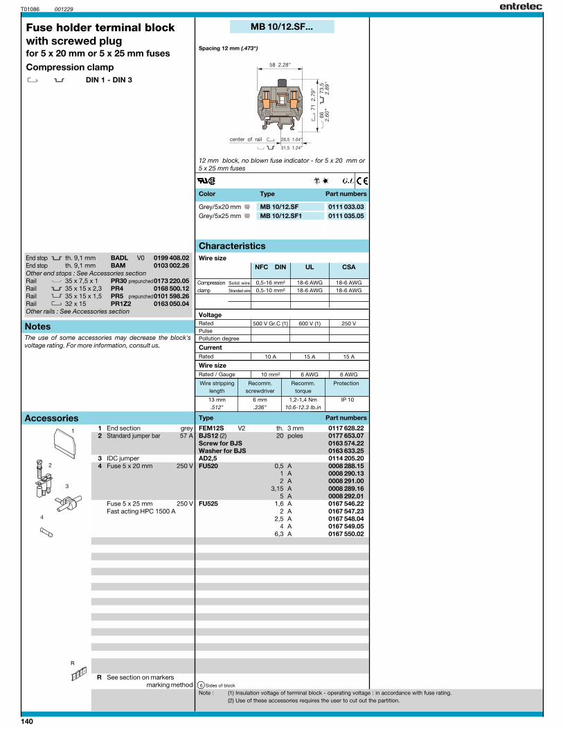
MB 10/12.SF...
13 mm 6 mm 1,2-1,4 Nm IP 10.512" .236" 10.6-12.3 Ib.in
MB 10/12.SF 0111 033.03MB 10/12.SF1 0111 035.05
3
FEM12S V2 3 mm 0117 628.22BJS12 (2) 20 0177 653.07
0163 574.220163 633.25
AD2,5 0114 205.20FU520 0,5 A 0008 288.15
1 A 0008 290.132 A 0008 291.00
3,15 A 0008 289.165 A 0008 292.01
FU525 1,6 A 0167 546.22 2 A 0167 547.23
2,5 A 0167 548.044 A 0167 549.05
6,3 A 0167 550.02
6
2
4
R
BADL V0 0199 408.02BAM 0103 002.26
35 x 7,5 x 135 x 15 x 2,3 PR4 0168 500.1235 x 15 x 1,532 x 15 PR1Z2 0163 050.04
End stop th. 9,1 mmEnd stop th. 9,1 mmOther end stops : See Accessories sectionRail PR30 prepunched0173 220.05RailRail PR5 prepunched0101 598.26RailOther rails : See Accessories section
Color Type Part numbers
Fuse holder terminal blockwith screwed plugfor 5 x 20 mm or 5 x 25 mm fuses
Compression clampDIN 1 - DIN 3
1 End section grey2 Standard jumper bar 57 A
3 IDC jumper4 Fuse 5 x 20 mm 250 V
Fuse 5 x 25 mm 250 VFast acting HPC 1500 A
R See section on markersmarking method
Spacing 12 mm (.473")
12 mm block, no blown fuse indicator - for 5 x 20 mm or5 x 25 mm fuses
Note : (1) Insulation voltage of terminal block - operating voltage : in accordance with fuse rating.(2) Use of these accessories requires the user to cut out the partition.
Grey/5x20 mmGrey/5x25 mm
th.poles
Screw for BJSWasher for BJS
Sides of block
Characteristics
Type Part numbers
Rated
Rated / Gauge
Wire size
Current
Wire size
Notes
Accessories
Wire stripping Recomm. Recomm. Protectionlength screwdriver torque
Compression Solid wire
clamp Stranded wire
RatedPulsePollution degree
Voltage
The use of some accessories may decrease the block'svoltage rating. For more information, consult us.
141
0,5-16 mm² 18-6 AWG 18-6 AWG0,5-10 mm² 18-6 AWG 18-6 AWG
500 V Gr.C (1) 600 V (1) 250(SFL) 24(SFD)
10 A 15 A 15 A
10 mm² 6 AWG 6 AWG
0,5-16 mm² 18-6 AWG 18-6 AWG0,5-10 mm² 18-6 AWG 18-6 AWG
500 V Gr.C (1) 600 V (1) 24 V
10 A 15 A 15 A
10 mm² 6 AWG 6 AWG
NFC DIN UL CSA NFC DIN UL CSA
MB 10/12.SF...
001229
13 mm 6 mm 1,2-1,4 Nm IP 10.512" .236" 10.6-12.3 Ib.in
MB 10/12.SFD1
MB 10/12.SFD1 0111 038.10
13 mm 6 mm 1,2-1,4 Nm IP 10.512" .236" 10.6-12.3 Ib.in
MB 10/12.SFL 0111 034.04MB 10/12.SFD 0111 037.07
FEM12S V2 3 mm 0117 628.22AD2,5 24 A 0114 205.20FU520 0,5 A 0008 288.15
1 A 0008 290.132 A 0008 291.00
3,15 A 0008 289.165 A 0008 292.01
ACD13.10 0118 683.23
6
T01087
1
2
4
3
R
BADL V0 0199 408.02BAM 0103 002.26
35 x 7,5 x 135 x 15 x 2,3 PR4 0168 500.1235 x 15 x 1,532 x 15 PR1Z2 0163 050.04
FEM12S V2 3 mm 0117 628.22AD2,5 24 A 0114 205.20FU520 0,5 A 0008 288.15
1 A 0008 290.132 A 0008 291.00
3,15 A 0008 289.165 A 0008 292.01
6
End stop th. 9,1 mmEnd stop th. 9,1 mmOther end stops : See Accessories sectionRail PR30 prepunched0173 220.05RailRail PR5 prepunched0101 598.26RailOther rails : See Accessories section
Color Type Part numbers Colour Type Part numbers
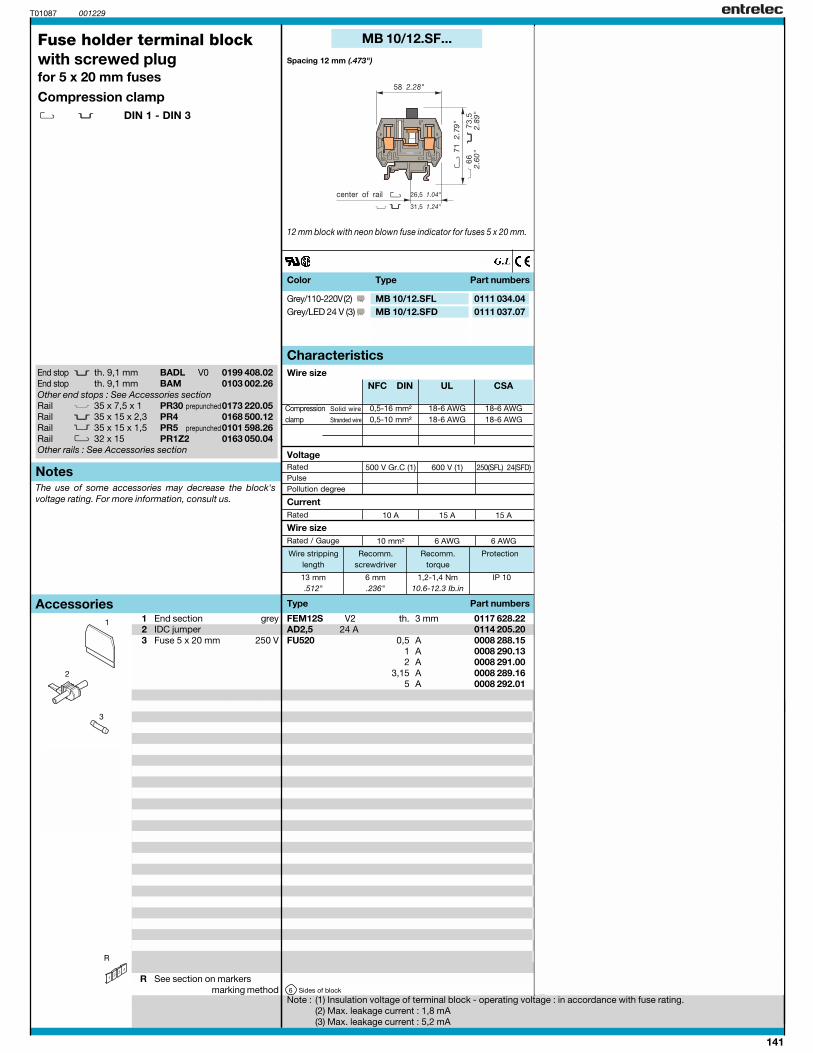
Spacing 12 mm (.473")Spacing 12 mm (.473")
1 End section grey2 IDC jumper3 Fuse 5 x 20 mm 250 V
4 Removable locking foot greyRails ,
R See section on markersmarking method
12 mm block without foot, with neon fusion indicator forfuses 5 x 20 mm.
12 mm block with neon blown fuse indicator for fuses 5 x 20 mm.
th.
Sides of block
Grey/LED 24 V (3)Grey/110-220V (2)Grey/LED 24 V (3)
th.
Sides of block
Fuse holder terminal blockwith screwed plugfor 5 x 20 mm fuses
Compression clampDIN 1 - DIN 3
Characteristics Characteristics
Note : (1) Insulation voltage of terminal block - operating voltage : in accordance with fuse rating.(2) Max. leakage current : 1,8 mA(3) Max. leakage current : 5,2 mA
Type Part numbers
Rated
Rated / Gauge
Wire size
Current
Wire size
Notes
Type Part numbers
Rated
Rated / Gauge
Wire size
Current
Wire size
Accessories
Wire stripping Recomm. Recomm. Protectionlength screwdriver torque
Wire stripping Recomm. Recomm. Protectionlength screwdriver torque
Compression Solid wire
clamp Stranded wire
RatedPulsePollution degree
VoltageRatedPulsePollution degree
Compression Solid wire
clamp Stranded wire
Voltage
The use of some accessories may decrease the block'svoltage rating. For more information, consult us.

142
0,5-16 mm² 22-10 AWG 6 AWG max.0,5-10 mm² 22-10 AWG 6 AWG max.
750 V Gr.C (1) 600 V (1) 600 V (1)
16 A 16 A 16 A
10 mm² 10 AWG 6 AWG
0,5-16 mm² 22-10 AWG 6 AWG max.0,5-10 mm² 22-10 AWG 6 AWG max.
750 V Gr.C (1) 600 V (1) 600 V (1)
16 A 16 A 16 A
10 mm² 10 AWG 6 AWG
NFC DIN UL CSA NFC DIN UL CSA
MU 10/13.SF1
001229
12 mm 5,5 mm 1,2-1,4 Nm IP 20.47" .22" 10.6-12.3 Ib.in NEMA 1
FEM13U V0 1,5 mm 0199 635.24FC2 2 mm 0007 865.26FC4 4 mm 0167 860.01AL2 2 mm 0163 043.21AL3 3 mm 0163 261.00AL4 4 mm 0163 262.01BJS131 10 0175 991.11VJS11 0163 394.26RDJ11 0168 783.01FU520 0,5 A 0008 288.15
1 A 0008 290.132 A 0008 291.00
3,15 A 0008 289.165 A 0008 292.01
2 A 0167 547.23 2,5 A 0167 548.04
4 A 0167 549.05 6,3 A 0167 550.02
LEN 110 - 230 VAC 0165 075.25480 VAC 0103 909.00
< 0,5 mA (110 & 480 VAC)< 0,7 mA (230 VAC)
PC 13 10 0173 510.20
11 17 26
MU 10/14,5.SF1
MU 10/14,5.SF1 0199 011.16
12 mm 5,5 mm 1,2-1,4 Nm IP 20.47" .22" 10.6-12.3 Ib.in NEMA 1
MU 10/13.SF1 0199 012.17
FC2 2 mm 0007 865.26FC4 4 mm 0167 860.01AL2 2 mm 0163 043.21AL3 3 mm 0163 261.00AL4 4 mm 0163 262.01
FU520 0,5 A 0008 288.151 A 0008 290.132 A 0008 291.00
3,15 A 0008 289.165 A 0008 292.01
FU525 1,6 A 0167 546.22 2 A 0167 547.23
2,5 A 0167 548.044 A 0167 549.05
6,3 A 0167 550.02LEN 110 - 230 VAC 0165 075.25
480 VAC 0103 909.00
< 0,5 mA (110 & 480 VAC)< 0,7 mA (230 VAC)
11 17 26
T01088
8
9
R
7
4, 5, 63
2
1
BADL V0 0199 408.02BAM 0103 002.26
35 x 7,5 x 135 x 15 x 2,3 PR4 0168 500.1235 x 15 x 1,532 x 15 PR1Z2 0163 050.04
End stop th. 9,1 mmEnd stop th. 9,1 mmOther end stops : See Accessories sectionRail PR30 prepunched0173 220.05RailRail PR5 prepunched0101 598.26RailOther rails : See Accessories section
Fuse holder terminal blocksfor 5 x 20 mm and 5 x 25 mm fusesCompression clamp
DIN 1 - DIN 3
Spacing 14,5 mm (.570")
14,5 mm block for blown fuse indicator (to be ordered separately).13 mm block for blown fuse indicator (to be ordered separately).
Spacing 13 mm (.512")
1 End section black2 Test plug
3 Test socket
4 Standard jumper bar5 Screw for BJ6 Washer for BJ7 Fuse 5 x 20 250 V
Fuse 5 x 25 250 VFast acting HPC 1500 A
8 Blown fuse indicator
9 Comb-type jumper bar 70 A
R See section on markersmarking method
th.DIA.DIA.DIA.DIA.DIA.
poles
Neon NeonLeakage current with neon indicator
poles
Sides of block
Black V0Black V0
closed block delivered with plateDIA.DIA.DIA.DIA.DIA.
Neon NeonLeakage current with neon indicator
Sides of block
Color Type Part numbers Color Type Part numbers
Characteristics Characteristics
Type Part numbers
Rated
Rated / Gauge
Wire size
Current
Wire size
Notes
Type Part numbers
Rated
Rated / Gauge
Wire size
Current
Wire size
Accessories
Wire stripping Recomm. Recomm. Protectionlength screwdriver torque
Wire stripping Recomm. Recomm. Protectionlength screwdriver torque
Compression Solid wire
clamp Stranded wire
RatedPulsePollution degree
VoltageRatedPulsePollution degree
Compression Solid wire
clamp Stranded wire
Voltage
The use of some accessories may decrease the block'svoltage rating. For more information, consult us.
Note : (1) Insulation voltage of terminal block - operating voltage : In accordance with fuse rating.
LED 24 VDC 0178 469.10Max. leakage current = 5.2mA
LED 24 VDC 0178 469.10Max. leakage current = 5.2mA
143
0,5-16 mm² 22-10 AWG 6 AWG max.
0,5-10 mm² 22-10 AWG 6 AWG max.
750 V Gr.C (1) 600 V (1) 600 V (1)
16 A 16 A 16 A
10 mm² 10 AWG 6 AWG
0,5-16 mm² 22-10 AWG 6 AWG max.
0,5-10 mm² 22-10 AWG 6 AWG max.
750 V Gr.C (1) 600 V (1) 600 V (1)
16 A 16 A 16 A
10 mm² 10 AWG 6 AWG
NFC DIN UL CSA NFC DIN UL CSA
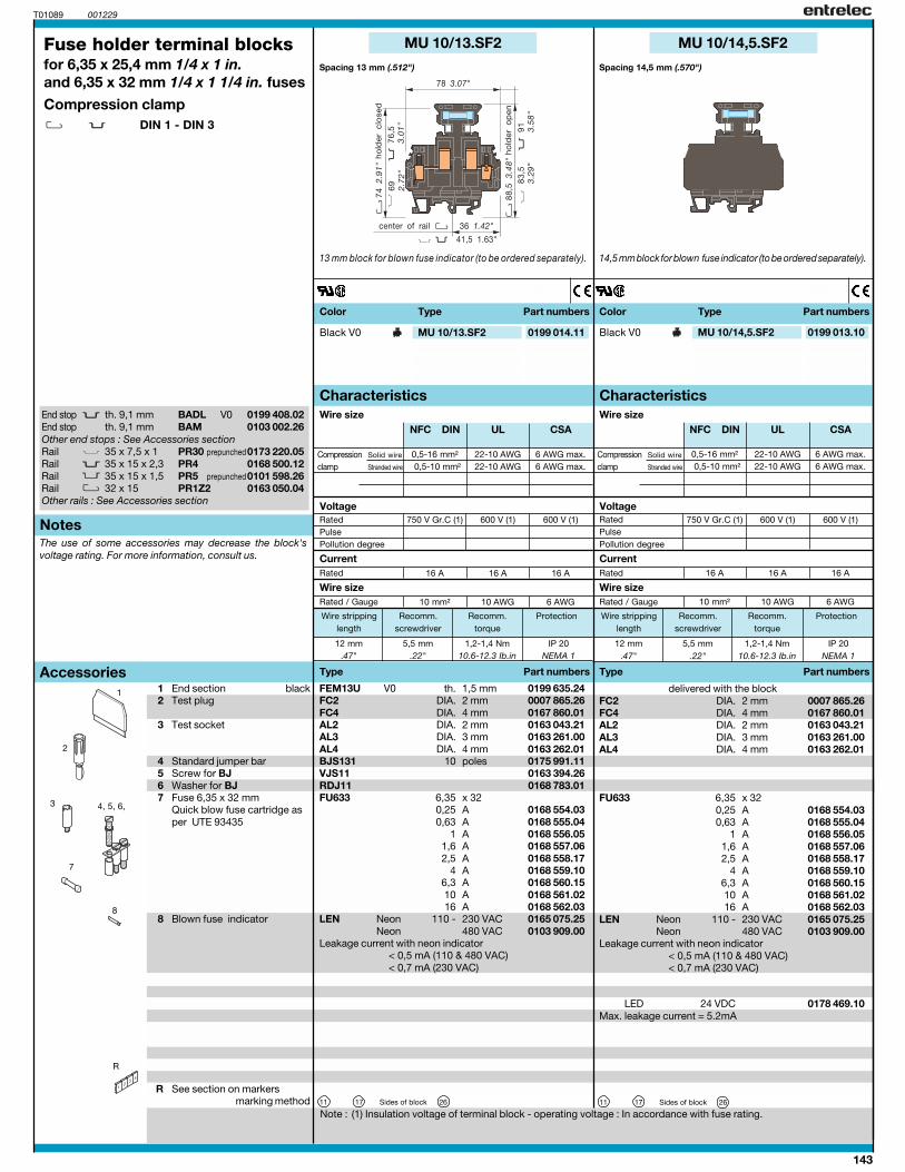
MU 10/13.SF2
001229
12 mm 5,5 mm 1,2-1,4 Nm IP 20.47" .22" 10.6-12.3 Ib.in NEMA 1
FEM13U V0 1,5 mm 0199 635.24FC2 2 mm 0007 865.26FC4 4 mm 0167 860.01AL2 2 mm 0163 043.21AL3 3 mm 0163 261.00AL4 4 mm 0163 262.01BJS131 10 0175 991.11VJS11 0163 394.26RDJ11 0168 783.01FU633 6,35 x 32
0,25 A 0168 554.030,63 A 0168 555.04
1 A 0168 556.051,6 A 0168 557.062,5 A 0168 558.17
4 A 0168 559.10 6,3 A 0168 560.15 10 A 0168 561.0216 A 0168 562.03
LEN 110 - 230 VAC 0165 075.25480 VAC 0103 909.00
< 0,5 mA (110 & 480 VAC)< 0,7 mA (230 VAC)
11 17 26
MU 10/14,5.SF2
MU 10/14,5.SF2 0199 013.10
12 mm 5,5 mm 1,2-1,4 Nm IP 20.47" .22" 10.6-12.3 Ib.in NEMA 1
MU 10/13.SF2 0199 014.11
FC2 2 mm 0007 865.26FC4 4 mm 0167 860.01AL2 2 mm 0163 043.21AL3 3 mm 0163 261.00AL4 4 mm 0163 262.01
FU633 6,35 x 320,25 A 0168 554.030,63 A 0168 555.04
1 A 0168 556.051,6 A 0168 557.062,5 A 0168 558.17
4 A 0168 559.10 6,3 A 0168 560.15 10 A 0168 561.0216 A 0168 562.03
LEN 110 - 230 VAC 0165 075.25480 VAC 0103 909.00
< 0,5 mA (110 & 480 VAC)< 0,7 mA (230 VAC)
11 17 26
T01089
1
R
8
7
3 4, 5, 6,
2
BADL V0 0199 408.02BAM 0103 002.26
35 x 7,5 x 135 x 15 x 2,3 PR4 0168 500.1235 x 15 x 1,532 x 15 PR1Z2 0163 050.04
End stop th. 9,1 mmEnd stop th. 9,1 mmOther end stops : See Accessories sectionRail PR30 prepunched0173 220.05RailRail PR5 prepunched0101 598.26RailOther rails : See Accessories section
Fuse holder terminal blocksfor 6,35 x 25,4 mm 1/4 x 1 in.and 6,35 x 32 mm 1/4 x 1 1/4 in. fuses
Compression clampDIN 1 - DIN 3
Spacing 14,5 mm (.570")
1 End section black2 Test plug
3 Test socket
4 Standard jumper bar5 Screw for BJ6 Washer for BJ7 Fuse 6,35 x 32 mm
Quick blow fuse cartridge asper UTE 93435
8 Blown fuse indicator
R See section on markersmarking method
14,5 mm block for blown fuse indicator (to be ordered separately).13 mm block for blown fuse indicator (to be ordered separately).
Spacing 13 mm (.512")
th.DIA.DIA.DIA.DIA.DIA.
poles
NeonNeon
Leakage current with neon indicator
Sides of block
delivered with the blockDIA.DIA.DIA.DIA.DIA.
NeonNeon
Leakage current with neon indicator
Sides of block
Black V0Black V0
Color Type Part numbers Color Type Part numbers
Characteristics Characteristics
Type Part numbers
Rated
Rated / Gauge
Wire size
Current
Wire size
Notes
Type Part numbers
Rated
Rated / Gauge
Wire size
Current
Wire size
Accessories
Wire stripping Recomm. Recomm. Protectionlength screwdriver torque
Wire stripping Recomm. Recomm. Protectionlength screwdriver torque
Compression Solid wire
clamp Stranded wire
RatedPulsePollution degree
VoltageRatedPulsePollution degree
Compression Solid wire
clamp Stranded wire
Voltage
The use of some accessories may decrease the block'svoltage rating. For more information, consult us.
Note : (1) Insulation voltage of terminal block - operating voltage : In accordance with fuse rating.
LED 24 VDC 0178 469.10Max. leakage current = 5.2mA

144
0,5-16 mm² 22-10 AWG 6 AWG max.0,5-10 mm² 22-10 AWG 6 AWG max.
750 V Gr.C 600 V 600 V
16 A 6 A 16 A
10 mm² 10 AWG 6 AWG
0,5-16 mm² 22-10 AWG 6 AWG max.0,5-10 mm² 22-10 AWG 6 AWG max.
750 V Gr.C 600 V 600 V
16 A 6 A 16 A
10 mm² 10 AWG 6 AWG
NFC DIN UL CSA NFC DIN UL CSA
MU 10/13.SN3
001229
12 mm 5,5 mm 1,2-1,4 Nm IP 20.47" .22" 10.6-12.3 Ib.in NEMA 1
FEM13U V0 1,5 mm 0199 635.24FC2 2 mm 0007 865.26FC4 4 mm 0167 860.01AL2 2 mm 0163 043.21AL3 3 mm 0163 261.00AL4 4 mm 0163 262.01BJS131 10 0175 991.11VJS11 0163 394.26RDJ11 0168 783.01PC13 10 0173 510.20CN 0173 582.15
11 17 26
MU 10/14,5.SN3
MU 10/14,5.SN3 0199 015.12
12 mm 5,5 mm 1,2-1,4 Nm IP 20.47" .22" 10.6-12.3 Ib.in NEMA 1
MU 10/13.SN3 0199 021.10
FC2 2 mm 0007 865.26FC4 4 mm 0167 860.01AL2 2 mm 0163 043.21AL3 3 mm 0163 261.00AL4 4 mm 0163 262.01
CN 0173 582.15
11 17 26
T01090
1
R
8
7
3 4, 5, 6
2
BADL V0 0199 408.02BAM 0103 002.26
35 x 7,5 x 135 x 15 x 2,3 PR4 0168 500.1235 x 15 x 1,532 x 15 PR1Z2 0163 050.04
End stop th. 9,1 mmEnd stop th. 9,1 mmOther end stops : See Accessories sectionRail PR30 prepunched0173 220.05RailRail PR5 prepunched0101 598.26RailOther rails : See Accessories section
Switch terminal blockswith neutral cartridgeCompression clamp
DIN 1 - DIN 3
Spacing 14,5 mm (.570")
1 End section black2 Test plug
3 Test socket
4 Standard jumper bar 57 A5 Screw for BJS6 Washer for BJS7 Comb-type jumper bar 70 A8 Neutral cartridge
R See section on markersmarking method
14,5 mm block with neutral cartridge locked on blue holder.13 mm block with neutral cartridge locked on blue holder.
Spacing 13 mm (.512")
th.DIA.DIA.DIA.DIA.DIA.
poles
poles
Sides of block
Black/Blue V0Black/Blue V0
delivered with the blockDIA.DIA.DIA.DIA.DIA.
Sides of block
Color Type Part numbers Color Type Part numbers
Characteristics Characteristics
Type Part numbers
Rated
Rated / Gauge
Wire size
Current
Wire size
Notes
Type Part numbers
Rated
Rated / Gauge
Wire size
Current
Wire size
Accessories
Wire stripping Recomm. Recomm. Protectionlength screwdriver torque
Wire stripping Recomm. Recomm. Protectionlength screwdriver torque
Compression Solid wire
clamp Stranded wire
RatedPulsePollution degree
VoltageRatedPulsePollution degree
Compression Solid wire
clamp Stranded wire
Voltage
The use of some accessories may decrease the block'svoltage rating. For more information, consult us.
145
0,5-16 mm² 22-10 AWG 22-8 AWG0,5-10 mm² 22-10 AWG 22-8 AWG
800 V (1) 600 V (1) 600 V (1)8 kV
3
16 A 25 A 25 A
10 mm² / A6 10 AWG 8 AWG
0,5-16 mm² 22-10 AWG 22-8 AWG0,5-10 mm² 22-10 AWG 22-8 AWG
800 V 600 V 600 V8 kV
3
16 A 25 A 25 A
10 mm² / A6 10 AWG 8 AWG
IEC UL CSANFC DIN
IEC UL CSANFC DIN
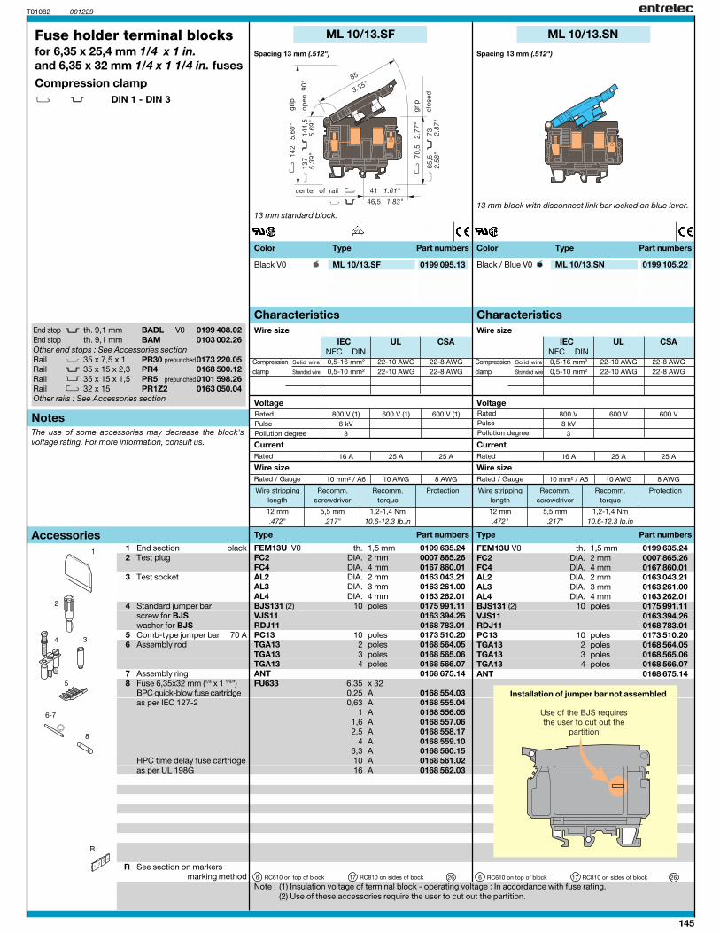
ML 10/13.SF
T01082 001229
12 mm 5,5 mm 1,2-1,4 Nm.472" .217" 10.6-12.3 Ib.in
FEM13U V0 1,5 mm 0199 635.24FC2 2 mm 0007 865.26FC4 4 mm 0167 860.01AL2 2 mm 0163 043.21AL3 3 mm 0163 261.00AL4 4 mm 0163 262.01BJS131 (2) 10 0175 991.11VJS11 0163 394.26RDJ11 0168 783.01PC13 10 0173 510.20TGA13 2 0168 564.05TGA13 3 0168 565.06TGA13 4 0168 566.07ANT 0168 675.14FU633 6,35 x 32
0,25 A 0168 554.030,63 A 0168 555.04
1 A 0168 556.051,6 A 0168 557.062,5 A 0168 558.17
4 A 0168 559.10 6,3 A 0168 560.15 10 A 0168 561.0216 A 0168 562.03
6 17 26
ML 10/13.SN
ML 10/13.SN 0199 105.22
12 mm 5,5 mm 1,2-1,4 Nm.472" .217" 10.6-12.3 Ib.in
ML 10/13.SF 0199 095.13
1 FEM13U V0 1,5 mm 0199 635.24FC2 2 mm 0007 865.26FC4 4 mm 0167 860.01AL2 2 mm 0163 043.21AL3 3 mm 0163 261.00AL4 4 mm 0163 262.01BJS131 (2) 10 0175 991.11VJS11 0163 394.26RDJ11 0168 783.01PC13 10 0173 510.20TGA13 2 0168 564.05TGA13 3 0168 565.06TGA13 4 0168 566.07ANT 0168 675.14
6 17 26
R
8
6-7
5
4 3
2
BADL V0 0199 408.02BAM 0103 002.26
35 x 7,5 x 135 x 15 x 2,3 PR4 0168 500.1235 x 15 x 1,532 x 15 PR1Z2 0163 050.04
End stop th. 9,1 mmEnd stop th. 9,1 mmOther end stops : See Accessories sectionRail PR30 prepunched0173 220.05RailRail PR5 prepunched0101 598.26RailOther rails : See Accessories section
Fuse holder terminal blocksfor 6,35 x 25,4 mm 1/4 x 1 in.and 6,35 x 32 mm 1/4 x 1 1/4 in. fuses
Compression clampDIN 1 - DIN 3
Spacing 13 mm (.512")Spacing 13 mm (.512")
1 End section black2 Test plug
3 Test socket
4 Standard jumper barscrew for BJSwasher for BJS
5 Comb-type jumper bar 70 A6 Assembly rod
7 Assembly ring8 Fuse 6,35x32 mm (1/4 x 1 1/4")
BPC quick-blow fuse cartridgeas per IEC 127-2
HPC time delay fuse cartridgeas per UL 198G
R See section on markersmarking method
13 mm standard block.
Note : (1) Insulation voltage of terminal block - operating voltage : In accordance with fuse rating.(2) Use of these accessories require the user to cut out the partition.
13 mm block with disconnect link bar locked on blue lever.
th.DIA.DIA.DIA.DIA.DIA.
poles
polespolespolespoles
RC610 on top of block RC810 on sides of bock
Black / Blue V0Black V0
th.DIA.DIA.DIA.DIA.DIA.
poles
polespolespolespoles
RC610 on top of block RC810 on sides of block
Color Type Part numbers Color Type Part numbers
Characteristics Characteristics
Type Part numbers
Rated
Rated / Gauge
Wire size
Current
Wire size
Notes
Type Part numbers
Rated
Rated / Gauge
Wire size
Current
Wire size
Accessories
Wire stripping Recomm. Recomm. Protectionlength screwdriver torque
Wire stripping Recomm. Recomm. Protectionlength screwdriver torque
Compression Solid wire
clamp Stranded wire
RatedPulsePollution degree
VoltageRatedPulsePollution degree
Compression Solid wire
clamp Stranded wire
Voltage
The use of some accessories may decrease the block'svoltage rating. For more information, consult us.
Installation of jumper bar not assembled

146
0,5-16 mm² 22-10 AWG 22-8 AWG0,5-10 mm² 22-10 AWG 22-8 AWG
800 V (1) 600 V (1) 600 V (1)8 kV
3
16 A 25 A 25 A
10 mm² / A6 10 AWG 8 AWG
0,5-16 mm² 22-10 AWG 22-8 AWG0,5-10 mm² 22-10 AWG 22-8 AWG
800 V (1) 600 V (1) 600 V (1)8 kV
3
16 A 25 A 25 A
10 mm² / A6 10 AWG 8 AWG
IEC UL CSANFC DIN
IEC UL CSANFC DIN
ML 10/13.SFL...
T01083 001229
12 mm 5,5 mm 1,2-1,4 Nm.472" .217" 10.6-12.3 Ib.in
FEM13U V0 1,5 mm 0199 635.24FC2 2 mm 0007 865.26FC4 4 mm 0167 860.01AL2 2 mm 0163 043.21AL3 3 mm 0163 261.00AL4 4 mm 0163 262.01BJS131 (2) 10 0175 991.11VJS11 0163 394.26RDJ11 0168 783.01PC13 10 0173 510.20TGA13 2 0168 564.05TGA13 3 0168 565.06TGA13 4 0168 566.07ANT 0168 675.14FU633 6,35 x 32
0,25 A 0168 554.030,63 A 0168 555.04
1 A 0168 556.051,6 A 0168 557.062,5 A 0168 558.17
4 A 0168 559.10 6,3 A 0168 560.15 10 A 0168 561.0216 A 0168 562.03
< 0,5 mA (110 & 480 V)< 0,7 mA (230 V)
6 17 26
ML 10/13.SFD...
ML 10/13.SFD 0199 166.26 ML 10/13.SFD1 0199 167.27
12 mm 5,5 mm 1,2-1,4 Nm.472" .217" 10.6-12.3 Ib.in
ML 10/13.SFL 0199 168.00 ML 10/13.SFL1 0199 165.25
1 FEM13U V0 1,5 mm 0199 635.24FC2 2 mm 0007 865.26FC4 4 mm 0167 860.01AL2 2 mm 0163 043.21AL3 3 mm 0163 261.00AL4 4 mm 0163 262.01BJS131 (2) 10 0175 991.11VJS11 0163 394.26RDJ11 0168 783.01PC13 10 0173 510.20TGA13 2 0168 564.05TGA13 3 0168 565.06TGA13 4 0168 566.07ANT 0168 675.14FU633 6,35 x 32
0,25 A 0168 554.030,63 A 0168 555.04
1 A 0168 556.051,6 A 0168 557.062,5 A 0168 558.17
4 A 0168 559.10 6,3 A 0168 560.15 10 A 0168 561.0216 A 0168 562.03
< 4,5 mA
6 17 26
R
8
6-7
5
43
2
BADL V0 0199 408.02BAM 0103 002.26
35 x 7,5 x 135 x 15 x 2,3 PR4 0168 500.1235 x 15 x 1,532 x 15 PR1Z2 0163 050.04
End stop th. 9,1 mmEnd stop th. 9,1 mmOther end stops : See Accessories sectionRail PR30 prepunched0173 220.05RailRail PR5 prepunched0101 598.26RailOther rails : See Accessories section
Color Type Part numbers Color Type Part numbers
Fuse holder terminal blocksfor 6,35 x 25,4 mm 1/4 x 1 in.and 6,35 x 32 mm 1/4 x 1 1/4 in. fuses
Compression clampDIN 1 - DIN 3
1 End section black2 Test plug
3 Test socket
4 Standard jumper barscrew for BJSwasher for BJS
5 Comb-type jumper bar 70 A6 Assembly rod
7 Assembly ring8 Fuse 6,35x32 mm (1/4 x 1 1/4")
BPC quick-blow fuse cartridgeas per IEC 127-2
HPC time delay fuse cartridgeas per UL 198G
R See section on markersmarking method
13 mm block with neon blown fuse indicator.
Spacing 13 mm (.512") Spacing 13 mm (.512")
13 mm block with LED blown fuse indicator.
* Blocks with LED indicator are labeled"+" on the outside of the lever. Theindicator can be reversed in the field ifrequired.
th.DIA.DIA.DIA.DIA.DIA.
poles
polespolespolespoles
Leakage currentwith neon indicator
RC610 on top of block RC810 on sides of block
Black V0/LED 24VBlack V0/LED 48V
Black V0/110-230VBlack V0/480V
th.DIA.DIA.DIA.DIA.DIA.
poles
polespolespolespoles
Leakage currentwith LED indicator 24 V or 48 V
RC610 on top of block RC810 on sides of block
Note : (1) Insulation voltage of terminal block - operating voltage : In accordance with fuse rating.(2) Use of these accessories requires the user to cut out the partition.
Characteristics Characteristics
Type Part numbers
Rated
Rated / Gauge
Wire size
Current
Wire size
Notes
Type Part numbers
Rated
Rated / Gauge
Wire size
Current
Wire size
Accessories
Wire stripping Recomm. Recomm. Protectionlength screwdriver torque
Wire stripping Recomm. Recomm. Protectionlength screwdriver torque
Compression Solid wire
clamp Stranded wire
RatedPulsePollution degree
VoltageRatedPulsePollution degree
Compression Solid wire
clamp Stranded wire
Voltage
The use of some accessories may decrease the block'svoltage rating. For more information, consult us.
147
0,5-10 mm² 24-8 AWG 24-8 AWG0,5-6 mm² 24-8 AWG 24-8 AWG
750 V Gr.C (1) 600 V (1) 600 V (1)
16 A 16 A 16 A
6 mm² 8 AWG 8 AWG
NFC DIN UL CSA
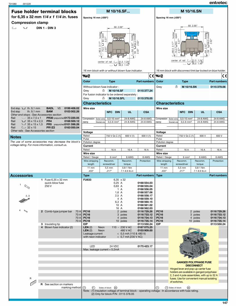
M 10/16.SF...
T01080 001229
11 mm 5,5 mm 0,8-1 Nm.433" .217" 7.1-8.9 Ib.in
FU633 6,35 x 320,25 A 0168 554.030,63 A 0168 555.04
1 A 0168 556.051,6 A 0168 557.062,5 A 0168 558.17
4 A 0168 559.106,3 A 0168 560.1510 A 0168 561.0216 A 0168 562.03
PC16 2 0116 729.26PC16 3 0116 733.12PC16 4 0116 734.13PC16 10 0116 735.14EIP 0113 550.24LEN (2) 110 - 230 V AC 0167 075.25LEN (2) 480 V AC 0103 909.00
< 0,5 mA (110 & 480 V)< 0,7 mA (230 V AC)
11 17 26
M 10/16.SF 0115 377.24
M 10/16.SFL 0115 378.05
4
1
2, 3
R
BADL V0 0199 408.02BAM 0103 002.26
35 x 7,5 x 135 x 15 x 2,3 PR4 0168 500.1235 x 15 x 1,532 x 15 PR1Z2 0163 050.04
0,5-10 mm² 24-8 AWG 24-8 AWG0,5-6 mm² 24-8 AWG 24-8 AWG
750 V Gr.C (1) 600 V 600 V
16 A 16 A 16 A
6 mm² 8 AWG 8 AWG
NFC DIN UL CSA
M 10/16.SN
11 mm 5,5 mm 0,8-1 Nm.433" .217" 7.1-8.9 Ib.in
PC16 2 0116 729.26PC16 3 0116 733.12PC16 4 0116 734.13PC16 10 0116 735.14EIP 0113 550.24
11 17 26
M 10/16.SN 0115 379.06
End stop th. 9,1 mmEnd stop th. 9,1 mmOther end stops : See Accessories sectionRail PR30 prepunched0173 220.05RailRail PR5 prepunched0101 598.26RailOther rails : See Accessories section
Fuse holder terminal blocksfor 6,35 x 32 mm 1/4 x 1 1/4 in. fusesCompression clamp
DIN 1 - DIN 3
Spacing 16 mm (.630")
1 Fuse 6,35 x 32 mmquick-blow fuse250 V
2 Comb-type jumper bar 70 A70 A70 A70 A
3 Insulating tip4 Blown fuse indicator (2)
R See section on markersmarking method
16 mm block with or without blown fuse indicator.
polespolespolespoles
NeonNeon
Leakage currentwith neon indicator
Sides of block
Without blown fuse indicator :GreyFor fusion indicator to be ordered separately :Grey
Note : (1) Insulation voltage of terminal block - operating voltage : In accordance with fuse rating.(2) Only for block P/N : 0115 378.05
Color Type Part numbers
Characteristics
Type Part numbers
Rated
Rated / Gauge
Wire size
Current
Wire size
Notes
Accessories
Wire stripping Recomm. Recomm. Protectionlength screwdriver torque
Compression Solid wire
clamp Stranded wire
RatedPulsePollution degree
Voltage
The use of some accessories may decrease the block'svoltage rating. For more information, consult us.
Spacing 16 mm (.630")
16 mm block with disconnect link bar locked on blue holder.
polespolespolespoles
Sides of block
Grey
Color Type Part numbers
Characteristics
Type Part numbers
Rated
Rated / Gauge
Wire size
Current
Wire size
Wire stripping Recomm. Recomm. Protectionlength screwdriver torque
Compression Solid wire
clamp Stranded wire
RatedPulsePollution degree
Voltage
GANGED POLYPHASE FUSEDISCONNECT
Hinged lever and pop-up carrier fuseholders are available in ganged polyphase2, 3 and 4 pole assemblies, with up to 32 Afuses. Use for convenient manual isolatingof switches.
LED 24 VDC 0175 423.17Max. leakage current = 5.2mA
148
0,5-10 mm² 24-8 AWG 24-8 AWG0,5-6 mm² 24-8 AWG 24-8 AWG
750 V Gr.C (1) 600 V 600 V (1)
20 A 16 A 20 A
6 mm² 8 AWG 8 AWG
0,5-10 mm² 24-8 AWG 24-8 AWG0,5-6 mm² 24-8 AWG 24-8 AWG
750 V Gr.C (1) 600 V 600 V (1)
20 A 16 A 20 A
6 mm² 8 AWG 8 AWG
NFC DIN UL CSA NFC DIN UL CSA
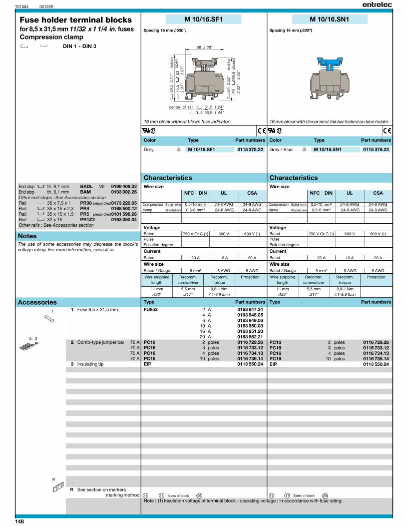
M 10/16.SF1
T01084 001229
11 mm 5,5 mm 0,8-1 Nm.433" .217" 7.1-8.9 Ib.in
FU853 2 A 0163 847.244 A 0163 848.056 A 0163 849.06
10 A 0163 850.0316 A 0163 851.2020 A 0163 852.21
PC16 2 0116 729.26PC16 3 0116 733.12PC16 4 0116 734.13PC16 10 0116 735.14EIP 0113 550.24
11 17 26
M 10/16.SN1
M 10/16.SN1 0115 376.23
11 mm 5,5 mm 0,8-1 Nm.433" .217" 7.1-8.9 Ib.in
M 10/16.SF1 0115 375.22
1
PC16 2 0116 729.26PC16 3 0116 733.12PC16 4 0116 734.13PC16 10 0116 735.14EIP 0113 550.24
11 17 26
2, 3
R
BADL V0 0199 408.02BAM 0103 002.26
35 x 7,5 x 135 x 15 x 2,3 PR4 0168 500.1235 x 15 x 1,532 x 15 PR1Z2 0163 050.04
End stop th. 9,1 mmEnd stop th. 9,1 mmOther end stops : See Accessories sectionRail PR30 prepunched0173 220.05RailRail PR5 prepunched0101 598.26RailOther rails : See Accessories section
Fuse holder terminal blocksfor 8,5 x 31,5 mm 11/32 x 1 1/4 in. fusesCompression clamp
DIN 1 - DIN 3
Spacing 16 mm (.630")
1 Fuse 8,5 x 31,5 mm
2 Comb-type jumper bar 70 A70 A70 A70 A
3 Insulating tip
R See section on markersmarking method
16 mm block without blown fuse indicator. 16 mm block with disconnect link bar locked on blue holder.
Spacing 16 mm (.630")
polespolespolespoles
Sides of block
Grey / BlueGrey
polespolespolespoles
Sides of block
Note : (1) Insulation voltage of terminal block - operating voltage : In accordance with fuse rating.
Color Type Part numbers Color Type Part numbers
Characteristics Characteristics
Type Part numbers
Rated
Rated / Gauge
Wire size
Current
Wire size
Notes
Type Part numbers
Rated
Rated / Gauge
Wire size
Current
Wire size
Accessories
Wire stripping Recomm. Recomm. Protectionlength screwdriver torque
Wire stripping Recomm. Recomm. Protectionlength screwdriver torque
Compression Solid wire
clamp Stranded wire
RatedPulsePollution degree
VoltageRatedPulsePollution degree
Compression Solid wire
clamp Stranded wire
Voltage
The use of some accessories may decrease the block'svoltage rating. For more information, consult us.

149
NOTES

150
IEC UL CSA IEC UL CSA IEC UL CSA IEC UL CSA
12 mm / .47"1.2 Nm / 10.6 Ib.in
400 600 60020 30 30
6 mm2 6 AWG 6 AWG
0.5-1620-6 AWG 20-6 AWG
0.5-10A5
FE8.1 8711 568.01FE8.1 8711 568.11FE8.1 8711 568.12
FE8-10.N 8711 627.01 FE8.1N.C 8721 568.01
FE8.1N.C 8721 568.12
FE8.1 FE8-10.N FE8.1N.C FE8.1N
FE8.1N 8715 568.01
FE8.1N 8715 568.12
RC55 - RC510 RC55 - RC510RC55 - RC510RC55 - RC510
FT1 0399 371.13KE8-10 0206 125.24PCP.1.12 RAU8970 452.12PCP.1.13 RAU8970 452.13PCP.1.57 RAU8970 452.57PCP.2.12 RAU8970 453.12PCP.2.60 RAU8970 453.60PCP.3.12 RAU8970 454.12PCP.3.60 RAU8970 454.60PCP.4.12 RAU8970 455.12PCP.4.60 RAU8970 455.60FU853
BTVP15 RAU8970 460.01BTVP30 RAU8970 460.02
001229
R
1
4
2
3
5
FE8-1
FT1 0399 371.13KE8-10 0206 125.24PCP.1.12 RAU8970 452.12PCP.1.13 RAU8970 452.13PCP.1.57 RAU8970 452.57PCP.2.12 RAU8970 453.12PCP.2.60 RAU8970 453.60PCP.3.12 RAU8970 454.12PCP.3.60 RAU8970 454.60PCP.4.12 RAU8970 455.12PCP.4.60 RAU8970 455.60FU853
BTVP15 RAU8970 460.01BTVP30 RAU8970 460.02
FT1 0399 371.13KE8-10 0206 125.24PCP.1.12 RAU8970 452.12PCP.1.13 RAU8970 452.13PCP.1.57 RAU8970 452.57
FU853
BTVP15 RAU8970 460.01BTVP30 RAU8970 460.02
FT1 0399 371.13KE8-10 0206 125.24PCP.1.12 RAU8970 452.12PCP.1.13 RAU8970 452.13PCP.1.57 RAU8970 452.57PCP.2.12 RAU8970 453.12PCP.2.60 RAU8970 453.60PCP.3.12 RAU8970 454.12PCP.3.60 RAU8970 454.60PCP.4.12 RAU8970 455.12PCP.4.60 RAU8970 455.60FU853
BTVP15 RAU8970 460.01BTVP30 RAU8970 460.02
12 mm / .47"1.2 Nm / 10.6 Ib.in
690 600 60032 30 30
6 mm2 6 AWG 6 AWG
0.5-1620-6 AWG 20-6 AWG
0.5-10A5
12 mm / .47"1.2 Nm / 10.6 Ib.in
400 600 60020 30 30
6 mm2 8 AWG 8 AWG
0.5-1020-8 AWG 20-8 AWG
0.5-6A4
12 mm / .47"1.2 Nm / 10.6 Ib.in
400 600 60020 30 30
6 mm2 6 AWG 6 AWG
0.5-1620-6 AWG 20-6 AWG
0.5-10A5
Rail 35 x 7.5 x 1 PR30 prepunched 0164 800.03Rail 35 x 15 x 2.3 PR4 0168 500.12Rail 35 x 15 x 1.5 PR5 prepunched 0101 598.26
Spacing 17,6 mm (0.69")1 module
1 pole
Modular fuse-holderfor 8,5 x 31,5 mm 11/32 x 1 1/4 in. fuses
DIN 3
1 pole
Spacing 17,6 mm (0.69")1 module
Spacing 17,6 mm (0.69")1 module
2 poles : 1 phase + neutral
Type P/N Type P/N Type P/N
Rated voltage V AC ~/= DCRated current ARated wire size mm² / AWGWire stripping lengthRecommended torque
Characteristics
Type P/N
Solid wireStranded wireGauge
Wire size
mm2 AWG
StandardWith blown-fuse indicator 24-48 AC/DC / 48-115 VACWith blown-fuse indicator 115-690 VAC
Reference
Spacing 35,2 mm (1.39")2 modules
2 poles : 1 phase + neutral
1 Plate mounting kit2 Assembly Kit multipolar3 Flat pin jumper bar unipolar
63 A unipolarisolated IP20 unipolar(see accessories, bipolarpage 154) bipolar
tripolartripolar
tetrapolartetrapolar
4 8,5 x 31,5 mm fuses(see accessories, page 154)
5 Flat pin terminal 15 mm(25 mm²) 30 mm
R see section on markers
Type P/N Type P/N Type P/N Type P/NAccessories
IP20 protectionStandards : IEC 947-3 / 269-2
Blown fuse-indicator leakage current :< 0,5 mA at 24 V< 1 mA at 48 V< 2,5 mA at other voltages
The assembly of more than 3 modular fuse-holders equipped with fuses could downgraderated current. Consult us.
3.1"

151
IEC UL CSA IEC UL CSA IEC UL CSA
12 mm / .47"1.2 Nm / 10.6 Ib.in
400 600 60020 30 30
6 mm2 8 AWG 8 AWG
0.5-1020-8 AWG 20-8 AWG
0.5-6A4
FE8.3N.C 8726 568.13 FE8.3N 8716 568.01
FE8.3N 8716 568.12
FE8.4 8714 568.01
FE8.3N.C FE8.3N FE8.4
RC55 - RC510RC55 - RC510RC55 - RC510
FT1 0399 371.13KE8-10 0206 125.24
FU853
BTVP15 RAU8970 460.01BTVP30 RAU8970 460.02
001229FE8-2
FT1 0399 371.13KE8-10 0206 125.24PCP.1.12 RAU8970 452.12PCP.1.13 RAU8970 452.13PCP.1.57 RAU8970 452.57PCP.2.12 RAU8970 453.12PCP.2.60 RAU8970 453.60PCP.3.12 RAU8970 454.12PCP.3.60 RAU8970 454.60PCP.4.12 RAU8970 455.12PCP.4.60 RAU8970 455.60FU853
BTVP15 RAU8970 460.01BTVP30 RAU8970 460.02
FT1 0399 371.13KE8-10 0206 125.24PCP.1.12 RAU8970 452.12PCP.1.13 RAU8970 452.13PCP.1.57 RAU8970 452.57PCP.2.12 RAU8970 453.12PCP.2.60 RAU8970 453.60PCP.3.12 RAU8970 454.12PCP.3.60 RAU8970 454.60PCP.4.12 RAU8970 455.12PCP.4.60 RAU8970 455.60FU853
BTVP15 RAU8970 460.01BTVP30 RAU8970 460.02
12 mm / .47"1.2 Nm / 10.6 Ib.in
400 600 60020 30 30
6 mm2 6 AWG 6 AWG
0.5-1620-6 AWG 20-6 AWG
0.5-10A5
12 mm / .47"1.2 Nm / 10.6 Ib.in
400 600 60020 30 30
6 mm2 6 AWG 6 AWG
0.5-1620-6 AWG 20-6 AWG
0.5-10A5
IEC UL CSA
12 mm / .47"1.2 Nm / 10.6 Ib.in
400 600 60020 30 30
6 mm2 6 AWG 6 AWG
0.5-1620-6 AWG 20-6 AWG
0.5-10A5
FE8.2 8712 568.01
FE8.2
RC55 - RC510
FT1 0399 371.13KE8-10 0206 125.24PCP.1.12 RAU8970 452.12PCP.1.13 RAU8970 452.13PCP.1.57 RAU8970 452.57PCP.2.12 RAU8970 453.12PCP.2.60 RAU8970 453.60PCP.3.12 RAU8970 454.12PCP.3.60 RAU8970 454.60PCP.4.12 RAU8970 455.12PCP.4.60 RAU8970 455.60FU853
BTVP15 RAU8970 460.01BTVP30 RAU8970 460.02
IEC UL CSA
12 mm / .47"1.2 Nm / 10.6 Ib.in
400 600 60020 30 30
6 mm2 6 AWG 6 AWG
0.5-1620-6 AWG 20-6 AWG
0.5-10A5
FE8.3 8713 568.01
FE8.3
RC55 - RC510
FT1 0399 371.13KE8-10 0206 125.24PCP.1.12 RAU8970 452.12PCP.1.13 RAU8970 452.13PCP.1.57 RAU8970 452.57PCP.2.12 RAU8970 453.12PCP.2.60 RAU8970 453.60PCP.3.12 RAU8970 454.12PCP.3.60 RAU8970 454.60PCP.4.12 RAU8970 455.12PCP.4.60 RAU8970 455.60FU853
BTVP15 RAU8970 460.01BTVP30 RAU8970 460.02
Spacing 52,2 mm (2.08")3 modules
4 poles : 3 phases + neutral 4 poles : 3 phases + neutral
Spacing 70.4 mm (2.77")4 modules
Spacing 70,4 mm (2.77")4 modules
4 poles
Type P/N Type P/NType P/N
Type P/N Type P/N Type P/N
The assembly of more than 3 modular fuse-holders equipped with fuses could downgraderated current. Consult us.
Spacing 35,2 mm (1.39")2 modules
2 poles
Type P/N
Type P/N
Spacing 52,2 mm (2.08")3 modules
3 poles
Type P/N
Type P/N
152
IEC UL CSApending pending
IEC UL CSA IEC UL CSA IEC UL CSA
12 mm / .47"1.2 Nm / 10.6 Ib.in
690 600 60032 30 30
6 mm2 6 AWG 6 AWG
0.5-1620-6 AWG 20-6 AWG
0.5-10A5
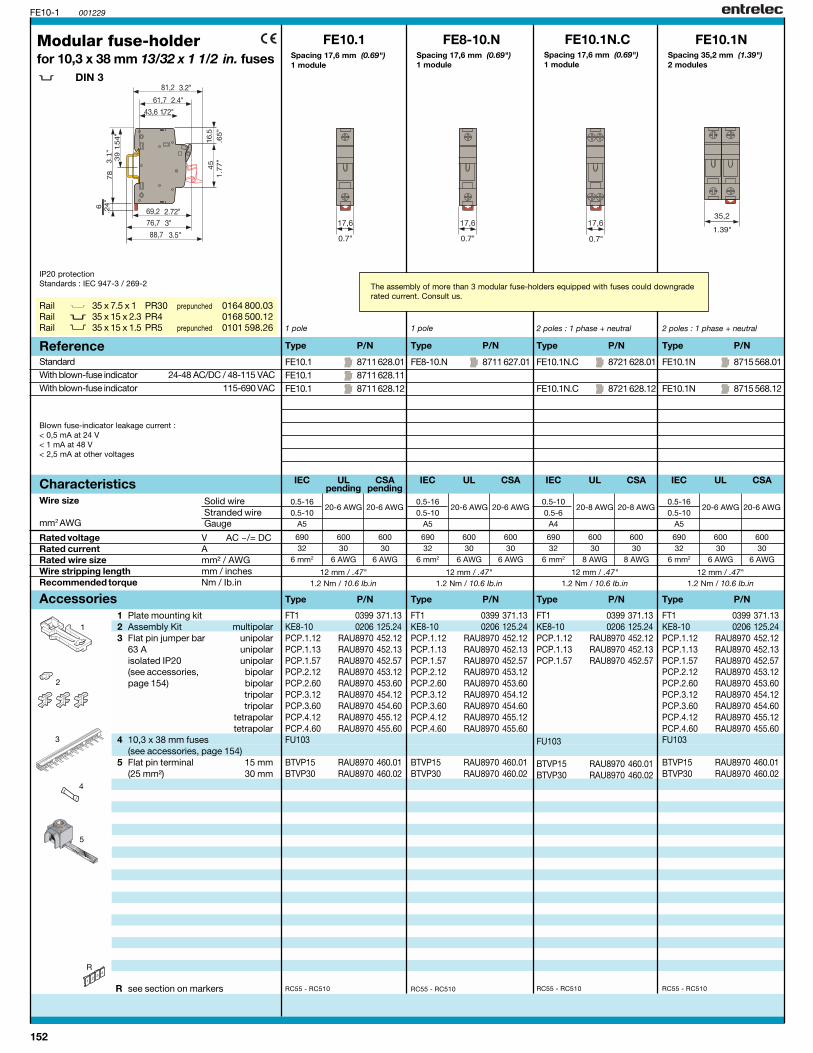
FE10.1 8711 628.01FE10.1 8711 628.11FE10.1 8711 628.12
FE8-10.N 8711 627.01 FE10.1N.C 8721 628.01
FE10.1N.C 8721 628.12
FE10.1 FE8-10.N FE10.1N.C FE10.1N
FE10.1N 8715 568.01
FE10.1N 8715 568.12
RC55 - RC510 RC55 - RC510RC55 - RC510RC55 - RC510
FT1 0399 371.13KE8-10 0206 125.24PCP.1.12 RAU8970 452.12PCP.1.13 RAU8970 452.13PCP.1.57 RAU8970 452.57PCP.2.12 RAU8970 453.12PCP.2.60 RAU8970 453.60PCP.3.12 RAU8970 454.12PCP.3.60 RAU8970 454.60PCP.4.12 RAU8970 455.12PCP.4.60 RAU8970 455.60FU103
BTVP15 RAU8970 460.01BTVP30 RAU8970 460.02
001229
3.1
"
R
1
4
2
3
5
FE10-1
FT1 0399 371.13KE8-10 0206 125.24PCP.1.12 RAU8970 452.12PCP.1.13 RAU8970 452.13PCP.1.57 RAU8970 452.57PCP.2.12 RAU8970 453.12PCP.2.60 RAU8970 453.60PCP.3.12 RAU8970 454.12PCP.3.60 RAU8970 454.60PCP.4.12 RAU8970 455.12PCP.4.60 RAU8970 455.60
BTVP15 RAU8970 460.01BTVP30 RAU8970 460.02
FT1 0399 371.13KE8-10 0206 125.24PCP.1.12 RAU8970 452.12PCP.1.13 RAU8970 452.13PCP.1.57 RAU8970 452.57
FU103
BTVP15 RAU8970 460.01BTVP30 RAU8970 460.02
FT1 0399 371.13KE8-10 0206 125.24PCP.1.12 RAU8970 452.12PCP.1.13 RAU8970 452.13PCP.1.57 RAU8970 452.57PCP.2.12 RAU8970 453.12PCP.2.60 RAU8970 453.60PCP.3.12 RAU8970 454.12PCP.3.60 RAU8970 454.60PCP.4.12 RAU8970 455.12PCP.4.60 RAU8970 455.60FU103
BTVP15 RAU8970 460.01BTVP30 RAU8970 460.02
12 mm / .47"1.2 Nm / 10.6 Ib.in
690 600 60032 30 30
6 mm2 6 AWG 6 AWG
0.5-1620-6 AWG 20-6 AWG
0.5-10A5
12 mm / .47"1.2 Nm / 10.6 Ib.in
690 600 60032 30 30
6 mm2 8 AWG 8 AWG
0.5-1020-8 AWG 20-8 AWG
0.5-6A4
12 mm / .47"1.2 Nm / 10.6 Ib.in
690 600 60032 30 30
6 mm2 6 AWG 6 AWG
0.5-1620-6 AWG 20-6 AWG
0.5-10A5
Rail 35 x 7.5 x 1 PR30 prepunched 0164 800.03Rail 35 x 15 x 2.3 PR4 0168 500.12Rail 35 x 15 x 1.5 PR5 prepunched 0101 598.26
Spacing 17,6 mm (0.69")1 module
1 pole
Modular fuse-holderfor 10,3 x 38 mm 13/32 x 1 1/2 in. fuses
DIN 3
1 pole
Spacing 17,6 mm (0.69")1 module
Spacing 17,6 mm (0.69")1 module
2 poles : 1 phase + neutral
Type P/N Type P/N Type P/N
Rated voltage V AC ~/= DCRated current ARated wire size mm² / AWGWire stripping length mm / inchesRecommended torque Nm / Ib.in
Characteristics
Type P/N
Solid wireStranded wireGauge
Wire size
mm2 AWG
StandardWith blown-fuse indicator 24-48 AC/DC / 48-115 VACWith blown-fuse indicator 115-690 VAC
Reference
Spacing 35,2 mm (1.39")2 modules
2 poles : 1 phase + neutral
1 Plate mounting kit2 Assembly Kit multipolar3 Flat pin jumper bar unipolar
63 A unipolarisolated IP20 unipolar(see accessories, bipolarpage 154) bipolar
tripolartripolar
tetrapolartetrapolar
4 10,3 x 38 mm fuses(see accessories, page 154)
5 Flat pin terminal 15 mm(25 mm²) 30 mm
R see section on markers
Type P/N Type P/N Type P/N Type P/NAccessories
IP20 protectionStandards : IEC 947-3 / 269-2
Blown fuse-indicator leakage current :< 0,5 mA at 24 V< 1 mA at 48 V< 2,5 mA at other voltages
The assembly of more than 3 modular fuse-holders equipped with fuses could downgraderated current. Consult us.

153
IEC UL CSA IEC UL CSA IEC UL CSApending pending
12 mm / .47"1.2 Nm / 10.6 Ib.in
690 600 60032 30 30
6 mm2 8 AWG 8 AWG
0.5-1020-8 AWG 20-8 AWG
0.5-6A4
FE10.3N.C 8726 628.01 FE10.3N 8716 628.01
FE10.3N 8716 628.12
FE10.4 8724 628.01
FE10.3N.C FE10.3N FE10.4
RC55 - RC510RC55 - RC510RC55 - RC510
FT1 0399 371.13KE8-10 0206 125.24
FU103
BTVP15 RAU8970 460.01BTVP30 RAU8970 460.02
001229FE10-2
FT1 0399 371.13KE8-10 0206 125.24PCP.1.12 RAU8970 452.12PCP.1.13 RAU8970 452.13PCP.1.57 RAU8970 452.57PCP.2.12 RAU8970 453.12PCP.2.60 RAU8970 453.60PCP.3.12 RAU8970 454.12PCP.3.60 RAU8970 454.60PCP.4.12 RAU8970 455.12PCP.4.60 RAU8970 455.60FU103
BTVP15 RAU8970 460.01BTVP30 RAU8970 460.02
FT1 0399 371.13KE8-10 0206 125.24PCP.1.12 RAU8970 452.12PCP.1.13 RAU8970 452.13PCP.1.57 RAU8970 452.57PCP.2.12 RAU8970 453.12PCP.2.60 RAU8970 453.60PCP.3.12 RAU8970 454.12PCP.3.60 RAU8970 454.60PCP.4.12 RAU8970 455.12PCP.4.60 RAU8970 455.60FU103
BTVP15 RAU8970 460.01BTVP30 RAU8970 460.02
12 mm / .47"1.2 Nm / 10.6 Ib.in
690 600 60032 30 30
6 mm2 6 AWG 6 AWG
0.5-1620-6 AWG 20-6 AWG
0.5-10A5
12 mm / .47"1.2 Nm / 10.6 Ib.in
690 600 60032 30 30
6 mm2 6 AWG 6 AWG
0.5-1620-6 AWG 20-6 AWG
0.5-10A5
IEC UL CSApending pending
12 mm / .47"1.2 Nm / 10.6 Ib.in
690 600 60032 30 30
6 mm2 6 AWG 6 AWG
0.5-1620-6 AWG 20-6 AWG
0.5-10A5
FE10.2 8712 628.01
FE10.2
RC55 - RC510
FT1 0399 371.13KE8-10 0206 125.24PCP.1.12 RAU8970 452.12PCP.1.13 RAU8970 452.13PCP.1.57 RAU8970 452.57PCP.2.12 RAU8970 453.12PCP.2.60 RAU8970 453.60PCP.3.12 RAU8970 454.12PCP.3.60 RAU8970 454.60PCP.4.12 RAU8970 455.12PCP.4.60 RAU8970 455.60FU103
BTVP15 RAU8970 460.01BTVP30 RAU8970 460.02
IEC UL CSApending pending
12 mm / .47"1.2 Nm / 10.6 Ib.in
690 600 60032 30 30
6 mm2 6 AWG 6 AWG
0.5-1620-6 AWG 20-6 AWG
0.5-10A5
FE10.3 8713 628.01
FE10.3
RC55 - RC510
FT1 0399 371.13KE8-10 0206 125.24PCP.1.12 RAU8970 452.12PCP.1.13 RAU8970 452.13PCP.1.57 RAU8970 452.57PCP.2.12 RAU8970 453.12PCP.2.60 RAU8970 453.60PCP.3.12 RAU8970 454.12PCP.3.60 RAU8970 454.60PCP.4.12 RAU8970 455.12PCP.4.60 RAU8970 455.60FU103
BTVP15 RAU8970 460.01BTVP30 RAU8970 460.02
Spacing 52,2 mm (2.08")3 modules
4 poles : 3 phases + neutral 4 poles : 3 phases + neutral
Spacing 70.4 mm (2.77")4 modules
Spacing 70,4 mm (2.77")4 modules
4 poles
Type P/N Type P/NType P/N
Type P/N Type P/N Type P/N
The assembly of more than 3 modular fuse-holders equipped with fuses could downgraderated current. Consult us.
Spacing 35,2 mm (1.39")2 modules
2 poles
Type P/N
Type P/N
Spacing 52,2 mm (2.08")3 modules
3 poles
Type P/N
Type P/N

154
FENT_ACC
FT1 0399 371.13
KE8-10 0206 125.24
001229
Fuses
Plate mounting
Assembly kit
2 poles assembly
Terminal block for 25 mm² wire
Jumper bar
With spadeWith flat pin
With spade
With flat pin
isolated flat pin 10 mm2isolated spade 10 mm2
Screw (M4) not delivered
Number Number Dimensions Type Part numberof poles of modules (mm)
1 12 210 PCP.1.12 RAU8970 452.121 13 225 PCP.1.13 RAU8970 452.131 57 1000 PCP.1.57 RAU8970 452.572 12 210 PCP.2.12 RAU8970 453.122 60 1065 PCP.2.60 RAU8970 453.603 12 210 PCP.3.12 RAU8970 454.123 60 1065 PCP.3.60 RAU8970 454.604 12 210 PCP.4.12 RAU8970 455.124 60 1065 PCP.4.60 RAU8970 455.60
Model Dimensions Type Part number(mm)
with flat pin 15 BTVP 15 RAU8970 460.0130 BTVP 30* RAU8970 460.02
with spade 15 BTVF 15 RAU8970 461.0130 BTVF 30* RAU8970 461.02
* to be used with jumper bars
Number Number Dimensions Type Part numberof poles of modules (mm)
1 12 210 PCF.1.12 RAU8970 456.121 57 1000 PCF.1.57 RAU8970 456.572 12 210 PCF.2.12 RAU8970 457.122 60 1065 PCF.2.60 RAU8970 457.603 12 210 PCF.3.12 RAU8970 458.123 60 1065 PCF.3.60 RAU8970 458.604 12 210 PCF.4.12 RAU8970 459.124 60 1065 PCF.4.60 RAU8970 459.60
Holes Ø 4,2or Ø M 4
The kit is composed of 10 packages of these 4 parts.
FU103 - 10,3 x 38 mm - 500 V
Current Distribution (gG) Motor protection (aM)
0,6 A consult us 0167 086 111 A consult us 0167 087.122 A 0167 076.26 0167 088.234 A 0167 077.27 0167 089.246 A 0167 078.00 0167 090.218 A 0167 079.01 0167 091.1610 A 0167 080.27 0167 092.1712 A 0167 081.14 consult us16 A 0167 082.15 0167 094.1120 A 0167 083.16 0167 095.1225 A 0167 084.17 consult us32 A 0167 085.10 consult us
FU853 - 8,5 x 31,5 mm
Current Part number
2 A 0167 086 114 A 0167 087.126 A 0167 076.2610 A 0167 077.2716 A 0167 078.0020 A 0167 079.01
155
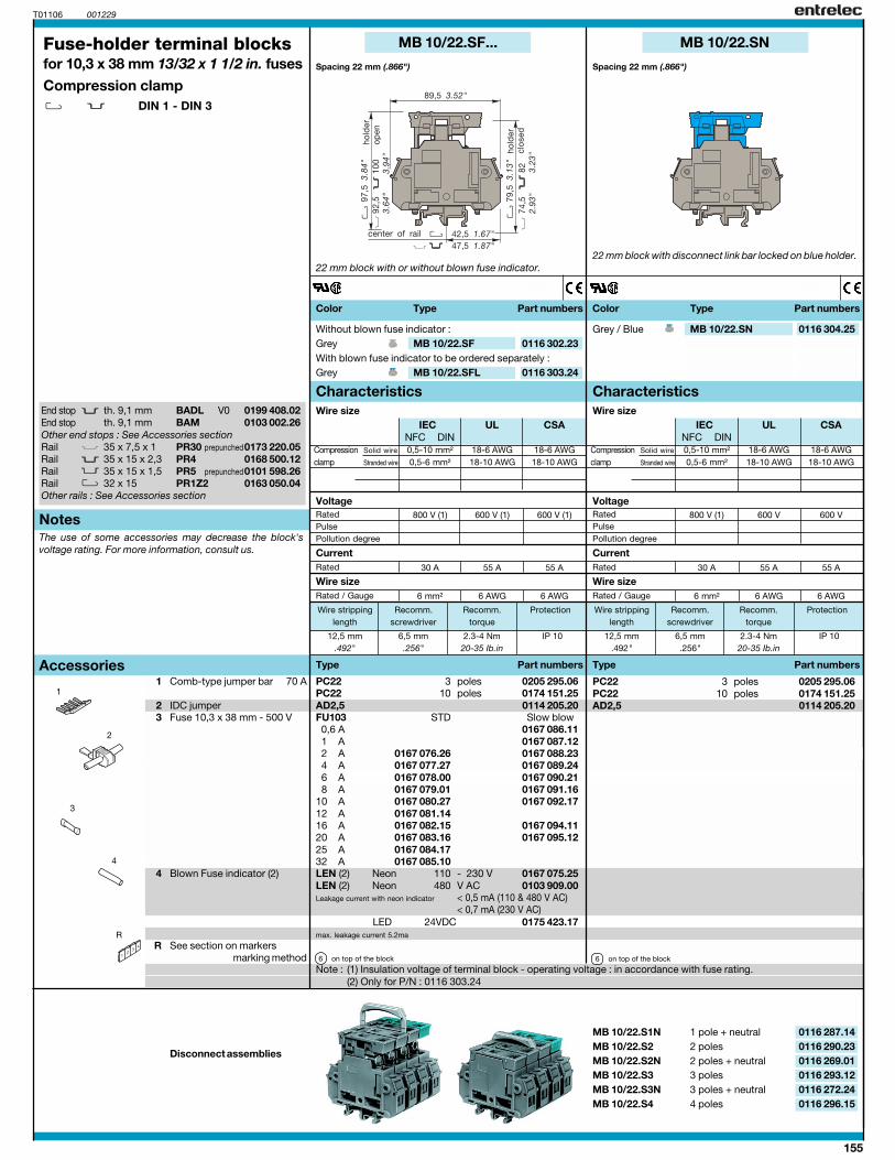
0,5-10 mm² 18-6 AWG 18-6 AWG0,5-6 mm² 18-10 AWG 18-10 AWG
800 V (1) 600 V (1) 600 V (1)
30 A 55 A 55 A
6 mm² 6 AWG 6 AWG
IEC UL CSANFC DIN
IEC UL CSANFC DIN
T01106 001229
MB 10/22.SF...
12,5 mm 6,5 mm 2.3-4 Nm IP 10.492" .256" 20-35 Ib.in
PC22 3 0205 295.06PC22 10 0174 151.25AD2,5 0114 205.20FU103 0,6 A 0167 086.11 1 A 0167 087.12 2 A 0167 076.26 0167 088.23 4 A 0167 077.27 0167 089.24 6 A 0167 078.00 0167 090.21 8 A 0167 079.01 0167 091.1610 A 0167 080.27 0167 092.1712 A 0167 081.1416 A 0167 082.15 0167 094.1120 A 0167 083.16 0167 095.1225 A 0167 084.1732 A 0167 085.10LEN (2) 110 - 230 V 0167 075.25LEN (2) 480 V AC 0103 909.00
< 0,5 mA (110 & 480 V AC)< 0,7 mA (230 V AC)
6
MB 10/22.SF 0116 302.23
MB 10/22.SFL 0116 303.24
PC22 3 0205 295.06PC22 10 0174 151.25AD2,5 0114 205.20
6
MB 10/22.S1N 0116 287.14MB 10/22.S2 0116 290.23MB 10/22.S2N 0116 269.01MB 10/22.S3 0116 293.12MB 10/22.S3N 0116 272.24MB 10/22.S4 0116 296.15
1
2
4
3
R
BADL V0 0199 408.02BAM 0103 002.26
35 x 7,5 x 135 x 15 x 2,3 PR4 0168 500.1235 x 15 x 1,532 x 15 PR1Z2 0163 050.04
0,5-10 mm² 18-6 AWG 18-6 AWG0,5-6 mm² 18-10 AWG 18-10 AWG
800 V (1) 600 V 600 V
30 A 55 A 55 A
6 mm² 6 AWG 6 AWG
MB 10/22.SN
12,5 mm 6,5 mm 2.3-4 Nm IP 10.492" .256" 20-35 Ib.in
MB 10/22.SN 0116 304.25
End stop th. 9,1 mmEnd stop th. 9,1 mmOther end stops : See Accessories sectionRail PR30 prepunched0173 220.05RailRail PR5 prepunched0101 598.26RailOther rails : See Accessories section
Spacing 22 mm (.866")
22 mm block with or without blown fuse indicator.
Note : (1) Insulation voltage of terminal block - operating voltage : in accordance with fuse rating.(2) Only for P/N : 0116 303.24
Fuse-holder terminal blocksfor 10,3 x 38 mm 13/32 x 1 1/2 in. fusesCompression clamp
DIN 1 - DIN 3
1 Comb-type jumper bar 70 A
2 IDC jumper3 Fuse 10,3 x 38 mm - 500 V
4 Blown Fuse indicator (2)
R See section on markersmarking method
Disconnect assemblies
polespoles
STD Slow blow
NeonNeon
Leakage current with neon indicator
on top of the block
Without blown fuse indicator :GreyWith blown fuse indicator to be ordered separately :Grey
polespoles
on top of the block
1 pole + neutral2 poles2 poles + neutral3 poles3 poles + neutral4 poles
Color Type Part numbers Color Type Part numbers
Characteristics Characteristics
Type Part numbers
Rated
Rated / Gauge
Wire size
Current
Wire size
Notes
Type Part numbers
Rated
Rated / Gauge
Wire size
Current
Wire size
Accessories
Wire stripping Recomm. Recomm. Protectionlength screwdriver torque
Wire stripping Recomm. Recomm. Protectionlength screwdriver torque
Compression Solid wire
clamp Stranded wire
RatedPulsePollution degree
VoltageRatedPulsePollution degree
Compression Solid wire
clamp Stranded wire
Voltage
The use of some accessories may decrease the block'svoltage rating. For more information, consult us.
22 mm block with disconnect link bar locked on blue holder.
Spacing 22 mm (.866")
Grey / Blue
LED 24VDC 0175 423.17max. leakage current 5.2ma
156
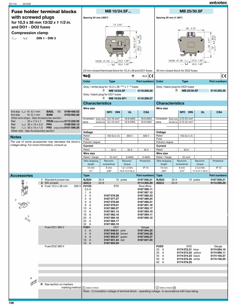
0,5-16 mm² 18-8 AWG 18-6 AWG0,5-10 mm² 18-8 AWG 18-6 AWG
750 Gr.C (1) 600 V 600 V
32 A 35 A 30 A
10 mm² 8 AWG 6 AWG
0,75-25 mm²0,75-25 mm²
750 Gr.C (1)
63 A
25 mm²
NFC DIN UL CSA NFC DIN UL CSA
T01110 001229
MB 10/24.SF... MB 25/30.SF
MB 10/24.SF 0116 299.20
MB 10/24.SF1 0116 298.27
13 mm 6 mm 1,2-1,4 Nm IP 10.51" .236" 10.6-12.3 Ib.in
BJS24 30 A 10 0167 856.21AD2,5 24 A 0114 205.20FU103 . 0,5 A 0167 086.11 1 A 0167 087.12 2 A 0167 076.26 0167 088.23 4 A 0167 077.27 0167 089.24 6 A 0167 078.00 0167 090.21 8 A 0167 079.01 0167 091.1610 A 0167 080.27 0167 092.1712 A 0167 081.14 0167 093.1016 A 0167 082.15 0167 094.1120 A 0167 083.16 0167 095.1225 A 0167 084.1732 A 0167 085.10FUD1 DO1 2 A 0167 848.01 0167 844.25 4 A 0167 849.02 0167 845.26 6 A 0167 850.07 0167 846.2710 A 0167 851.24 0167 847.2016 A 0167 852.25
6
MB 25/30.SF 0116 305.26
10 mm 8 mm 2-2,5 Nm IP 10.394" .315" 17.4-21.7 Ib.in
R
1
2
3
BJS24 30 A 10 0167 856.21AD2,5 24 A 0114 205.20
FUD2 DO220 A 0174 072.21 0174 094.1025 A 0174 073.22 0174 095.1135 A 0174 074.23 0174 104.2750 A 0174 075.24 0174 105.2063 A 0174 076.25
17 26
BADL V0 0199 408.02BAM 0103 002.26
35 x 7,5 x 1 PR30 0173 220.0535 x 15 x 2,3 PR4 0168 500.1235 x 15 x 1,5 PR5 0101 598.26
End stop th. 9,1 mmEnd stop th. 9,1 mmOther end stops : See Accessories sectionRail prepunchedRailRail prepunchedOther rails : See Accessories section
Spacing 30 mm (1.180")Spacing 24 mm (.950")
Fuse holder terminal blockswith screwed plugsfor 10,3 x 38 mm 13/32 x 1 1/2 in.and DO1 - DO2 fusesCompression clamp
DIN 1 - DIN 3
1 Standard jumper bar2 IDC jumper3 Fuse 10,3 x 38 mm 500 V
Fuse DO1 380 V
Fuse DO2 380 V
R See section on markersmarking method
24 mm closed thermoset block for 10,3 x 38 and DO1 fuses.
Note : (1) Insulation voltage of terminal block - operating voltage : In accordance with fuse rating.
30 mm closed block for DO2 fuses.
Grey / white plug for 10,3 x 38 13/32 x 1 1/2 fuses
Grey / black plug for DO1 fuses
poles
STD Slow Blow
Gaugepinkbrowngreenred
Sides of block
Grey / black plug for DO2 fuses
poles
Gaugeblueyellowblackwhite
Sides of block
Color Type Part numbers Color Type Part numbers
Characteristics Characteristics
Type Part numbers
Rated
Rated / Gauge
Wire size
Current
Wire size
Notes
Type Part numbers
Rated
Rated / Gauge
Wire size
Current
Wire size
Accessories
Wire stripping Recomm. Recomm. Protectionlength screwdriver torque
Wire stripping Recomm. Recomm. Protectionlength screwdriver torque
Compression Solid wire
clamp Stranded wire
RatedPulsePollution degree
VoltageRatedPulsePollution degree
Compression Solid wire
clamp Stranded wire
Voltage
The use of some accessories may decrease the block'svoltage rating. For more information, consult us.
157
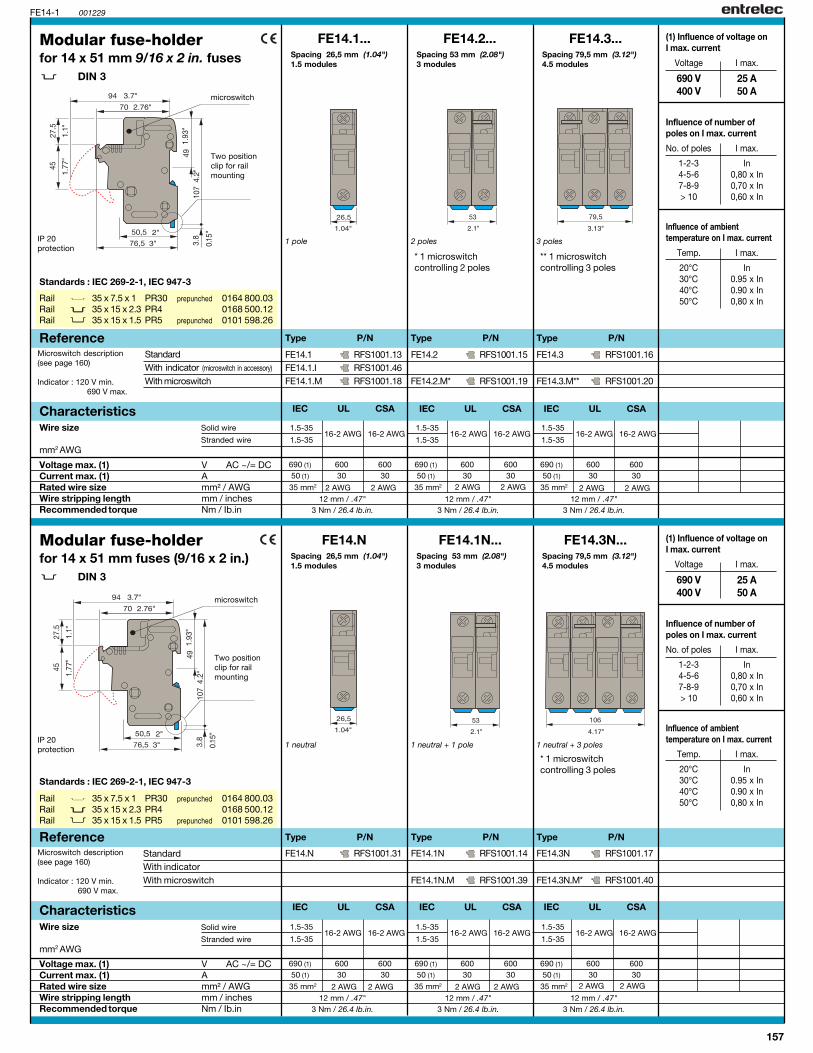
FE14.3N...FE14.1N...
12 mm / .47"3 Nm / 26.4 lb.in.
690 (1) 600 60050 (1) 30 30
FE14-1
FE14.1 RFS1001.13FE14.1.I RFS1001.46FE14.1.M RFS1001.18
FE14.2 RFS1001.15
FE14.2.M* RFS1001.19
FE14.3 RFS1001.16
FE14.3.M** RFS1001.20
FE14.2... FE14.3...
001229
FE14.1N RFS1001.14
FE14.1N.M RFS1001.39
FE14.3N RFS1001.17
FE14.3N.M* RFS1001.40
FE14.1...
FE14.N RFS1001.31
FE14.N
1.5-3516-2 AWG 16-2 AWG
1.5-35
12 mm / .47"3 Nm / 26.4 lb.in.
690 (1) 600 60050 (1) 30 30
1.5-3516-2 AWG 16-2 AWG
1.5-35
12 mm / .47"3 Nm / 26.4 lb.in.
690 (1) 600 60050 (1) 30 30
1.5-3516-2 AWG 16-2 AWG
1.5-35
12 mm / .47"3 Nm / 26.4 lb.in.
690 (1) 600 60050 (1) 30 30
1.5-3516-2 AWG 16-2 AWG
1.5-35
12 mm / .47"3 Nm / 26.4 lb.in.
690 (1) 600 60050 (1) 30 30
1.5-3516-2 AWG 16-2 AWG
1.5-35
12 mm / .47"3 Nm / 26.4 lb.in.
690 (1) 600 60050 (1) 30 30
1.5-3516-2 AWG 16-2 AWG
1.5-35
IEC UL CSA IEC UL CSAIEC UL CSA
IEC UL CSA IEC UL CSA IEC UL CSA
2 AWG 2 AWG 2 AWG 2 AWG 2 AWG 2 AWG
2 AWG 2 AWG 2 AWG 2 AWG 2 AWG 2 AWG
35 mm2 35 mm2 35 mm2
35 mm2 35 mm2 35 mm2
Rail 35 x 7.5 x 1 PR30 prepunched 0164 800.03Rail 35 x 15 x 2.3 PR4 0168 500.12Rail 35 x 15 x 1.5 PR5 prepunched 0101 598.26
Spacing 26,5 mm (1.04")1.5 modules
1 pole
Modular fuse-holderfor 14 x 51 mm 9/16 x 2 in. fuses
DIN 3
2 poles
Spacing 53 mm (2.08")3 modules
Spacing 79,5 mm (3.12")4.5 modules
3 poles
Type P/N Type P/N
Voltage max. (1) V AC ~/= DCCurrent max. (1) ARated wire size mm² / AWGWire stripping length mm / inchesRecommended torque Nm / Ib.in
Characteristics
Type P/N
Solid wire
Stranded wire
Wire size
mm2 AWG
Two positionclip for railmounting
Reference
IP 20protection
microswitch
* 1 microswitchcontrolling 2 poles
** 1 microswitchcontrolling 3 poles
Two positionclip for railmounting
microswitch
Modular fuse-holderfor 14 x 51 mm fuses (9/16 x 2 in.)
DIN 3
Spacing 79,5 mm (3.12")4.5 modules
1 neutral + 3 poles
Spacing 53 mm (2.08")3 modules
1 neutral + 1 pole
Type P/NType P/N
StandardWith indicatorWith microswitch
Voltage max. (1) V AC ~/= DCCurrent max. (1) ARated wire size mm² / AWGWire stripping length mm / inchesRecommended torque Nm / Ib.in
Wire size
mm2 AWG
Rail 35 x 7.5 x 1 PR30 prepunched 0164 800.03Rail 35 x 15 x 2.3 PR4 0168 500.12Rail 35 x 15 x 1.5 PR5 prepunched 0101 598.26
Characteristics
Reference
StandardWith indicator (microswitch in accessory)
With microswitch
Microswitch description(see page 160)
Indicator : 120 V min. 690 V max.
Microswitch description(see page 160)
Indicator : 120 V min.690 V max.
IP 20protection
* 1 microswitchcontrolling 3 poles
Spacing 26,5 mm (1.04")1.5 modules
1 neutral
Type P/N
(1) Influence of voltage onI max. current
Voltage I max.
690 V 25 A400 V 50 A
Influence of number ofpoles on I max. current
No. of poles I max.
1-2-3 In4-5-6 0,80 x In7-8-9 0,70 x In> 10 0,60 x In
Influence of ambienttemperature on I max. current
Temp. I max.
20°C In30°C 0.95 x In40°C 0.90 x In50°C 0,80 x In
Standards : IEC 269-2-1, IEC 947-3
Solid wire
Stranded wire

158
FJ27.2...FJ27.1...
FE21-27
FJ21.1 RFS1001.01FJ21.1.I RFS1001.04
FJ21.2 RFS1001.02FJ21.2.I RFS1001.05
FJ21.3 RFS1001.03FJ21.3.I RFS1001.06
FJ21.2... FJ21.3...
001229
FJ27.1 RFS1001.07FJ27.1.I RFS1001.10
FJ27.2 RFS1001.08FJ27.2.I RFS1001.11
FJ21.1...
2.5-5014-0 AWG 14-0 AWG
2.5-50
600 60030 30
13 mm / .51"4 Nm / 35.2 lb.in.
FJ27.3 RFS1001.09FJ27.3.I RFS1001.12
KJ21 RFS1001.33
KJ27 RFS1001.36
FJ27.3...
2.5-5014-0 AWG 14-0 AWG
2.5-50
600 60030 30
13 mm / .51"4 Nm / 35.2 lb.in.
2.5-5014-0 AWG 14-0 AWG
2.5-50
600 60030 30
13 mm / .51"4 Nm / 35.2 lb.in.
2.5-5014-0 AWG 14-0 AWG
2.5-50
600 60030 30
13 mm / .51"5.2 Nm / 45.8 lb.in.
2.5-5014-0 AWG 14-0 AWG
2.5-50
600 60030 30
13 mm / .51"5.2 Nm / 45.8 lb.in.
2.5-5014-0 AWG 14-0 AWG
2.5-50
600 60030 30
13 mm / .51"5.2 Nm / 45.8 lb.in.
IEC UL CSA IEC UL CSA IEC UL CSA
IEC UL CSA IEC UL CSA IEC UL CSA
0 AWG 0 AWG 0 AWG 0 AWG 0 AWG 0 AWG
0 AWG 0 AWG 0 AWG 0 AWG 0 AWG 0 AWG
Rail 35 x 7.5 x 1 PR30 prepunched 0164 800.03Rail 35 x 15 x 2.3 PR4 0168 500.12Rail 35 x 15 x 1.5 PR5 prepunched 0101 598.26
Spacing 32,5 mm (1.28")
1 pole
Modular fuse-holderfor 21 x 57 mm 13/16 x 2 1/4 in. fusesClass J - DIN 3
2 poles
Spacing 65 mm (2.56") Spacing 97,5 mm (3.84")
3 poles
Type P/N Type P/N
Voltage V AC ~/= DCCurrent ARated wire size mm² / AWGWire stripping length mm / inchesRecommended torque Nm / Ib.in
Characteristics
Type P/N
Solid wire
Stranded wire
Wire size
mm2 AWG
Two positionclip for railmounting
Reference
IP 20protection
Two positionclip for railmounting
Modular fuse-holderfor 27 x 60 mm fuses (1 1/16 x 2 3/8 in.)Class J - DIN 3
Spacing 80 mm (3.15")
2 poles
Spacing 40 mm (1.57")
1 pole
Type P/N Type P/NType P/N
StandardWith indicator
Voltage V AC ~/= DCCurrent ARated wire size mm² / AWGWire stripping length mm / inchesRecommended torque Nm / Ib.in
Solid wire
Stranded wireWire size
mm2 AWG
Rail 35 x 7.5 x 1 PR30 prepunched 0164 800.03Rail 35 x 15 x 2.3 PR4 0168 500.12Rail 35 x 15 x 1.5 PR5 prepunched 0101 598.26
Characteristics
Reference
StandardWith indicator
Indicator :90 VAC - 115 VDC min.600 VAC/DC max.
Indicator :90 VAC - 115 VDC min.600 VAC/DC max.
Assembly kit
3 poles
Assembly kitSpacing 120 mm (4.72")
IP 20protection
Standard : UL listed, file No E196143
Standard : UL listed, file No E196143
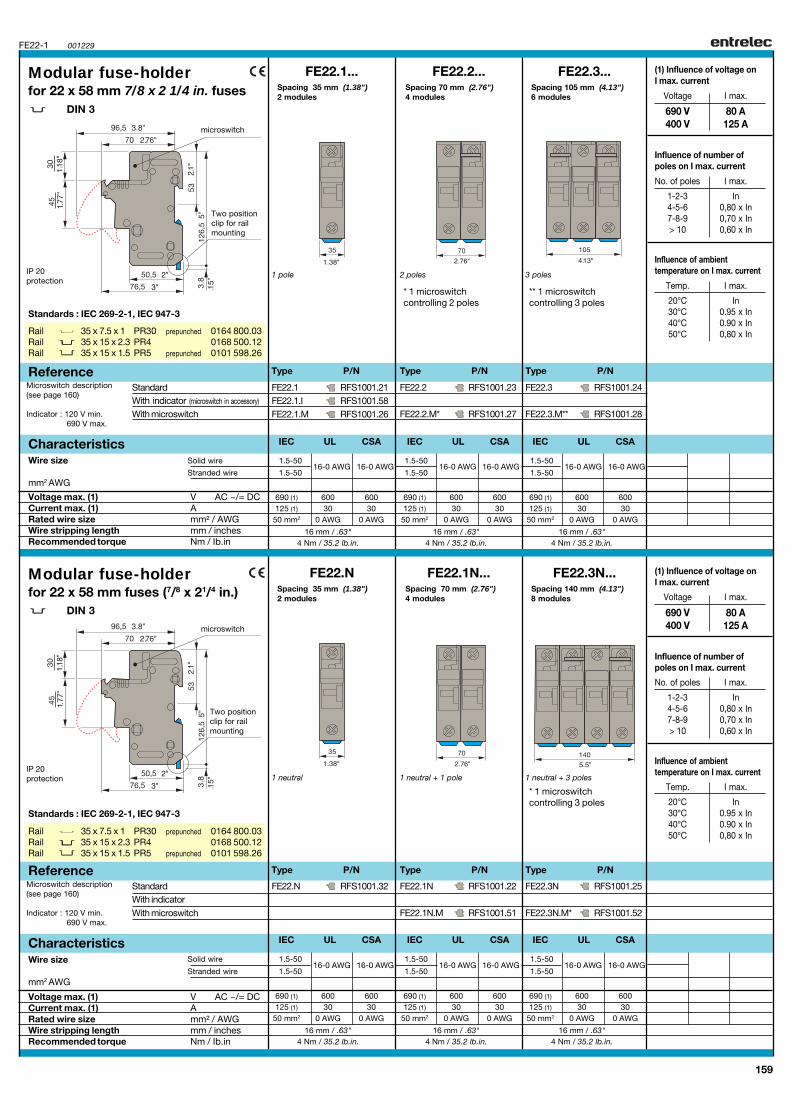
159
FE22.3N...FE22.1N...
FE22-1
FE22.N RFS1001.32
FE22.2 RFS1001.23
FE22.2.M* RFS1001.27
FE22.3 RFS1001.24
FE22.3.M** RFS1001.28
FE22.2... FE22.3...
001229
FE22.1N RFS1001.22
FE22.1N.M RFS1001.51
FE22.3N RFS1001.25
FE22.3N.M* RFS1001.52
FE22.N
FE22.1 RFS1001.21FE22.1.I RFS1001.58FE22.1.M RFS1001.26
FE22.1...
16 mm / .63"4 Nm / 35.2 lb.in.
690 (1) 600 600125 (1) 30 30
50 mm2 0 AWG 0 AWG
1.5-5016-0 AWG 16-0 AWG
1.5-50
16 mm / .63"4 Nm / 35.2 lb.in.
690 (1) 600 600125 (1) 30 30
50 mm2 0 AWG 0 AWG
1.5-5016-0 AWG 16-0 AWG
1.5-50
16 mm / .63"4 Nm / 35.2 lb.in.
690 (1) 600 600125 (1) 30 30
50 mm2 0 AWG 0 AWG
1.5-5016-0 AWG 16-0 AWG
1.5-50
16 mm / .63"4 Nm / 35.2 lb.in.
690 (1) 600 600125 (1) 30 30
50 mm2 0 AWG 0 AWG
1.5-5016-0 AWG 16-0 AWG
1.5-50
16 mm / .63"4 Nm / 35.2 lb.in.
690 (1) 600 600125 (1) 30 30
50 mm2 0 AWG 0 AWG
1.5-5016-0 AWG 16-0 AWG
1.5-50
16 mm / .63"4 Nm / 35.2 lb.in.
690 (1) 600 600125 (1) 30 30
50 mm2 0 AWG 0 AWG
1.5-5016-0 AWG 16-0 AWG
1.5-50
IEC UL CSA IEC UL CSAIEC UL CSA
IEC UL CSA IEC UL CSA IEC UL CSA
StandardWith indicator (microswitch in accessory)
With microswitch
Rail 35 x 7.5 x 1 PR30 prepunched 0164 800.03Rail 35 x 15 x 2.3 PR4 0168 500.12Rail 35 x 15 x 1.5 PR5 prepunched 0101 598.26
Spacing 35 mm (1.38")2 modules
1 pole
Modular fuse-holderfor 22 x 58 mm 7/8 x 2 1/4 in. fuses
DIN 3
2 poles
Spacing 70 mm (2.76")4 modules
Spacing 105 mm (4.13")6 modules
3 poles
Type P/N Type P/N
Voltage max. (1) V AC ~/= DCCurrent max. (1) ARated wire size mm² / AWGWire stripping length mm / inchesRecommended torque Nm / Ib.in
Characteristics
Type P/N
Solid wire
Stranded wire
Wire size
mm2 AWG
Two positionclip for railmounting
Reference
IP 20protection
microswitch
* 1 microswitchcontrolling 2 poles
** 1 microswitchcontrolling 3 poles
Two positionclip for railmounting
microswitch
Modular fuse-holderfor 22 x 58 mm fuses (7/8 x 21/4 in.)
DIN 3
Spacing 140 mm (4.13")8 modules
Spacing 70 mm (2.76")4 modules
Type P/NType P/N
Voltage max. (1) V AC ~/= DCCurrent max. (1) ARated wire size mm² / AWGWire stripping length mm / inchesRecommended torque Nm / Ib.in
Wire size
mm2 AWG
Rail 35 x 7.5 x 1 PR30 prepunched 0164 800.03Rail 35 x 15 x 2.3 PR4 0168 500.12Rail 35 x 15 x 1.5 PR5 prepunched 0101 598.26
Characteristics
Reference
Microswitch description(see page 160)
Indicator : 120 V min.690 V max.
1 neutral + 3 poles1 neutral + 1 pole
* 1 microswitchcontrolling 3 poles
Spacing 35 mm (1.38")2 modules
1 neutral
Type P/N
IP 20protection
StandardWith indicatorWith microswitch
Standards : IEC 269-2-1, IEC 947-3
Standards : IEC 269-2-1, IEC 947-3
Microswitch description(see page 160)
Indicator : 120 V min.690 V max.
(1) Influence of voltage onI max. current
Voltage I max.
690 V 80 A400 V 125 A
Influence of number ofpoles on I max. current
No. of poles I max.
1-2-3 In4-5-6 0,80 x In7-8-9 0,70 x In> 10 0,60 x In
Influence of ambienttemperature on I max. current
Temp. I max.
20°C In30°C 0.95 x In40°C 0.90 x In50°C 0,80 x In
Solid wire
Stranded wire
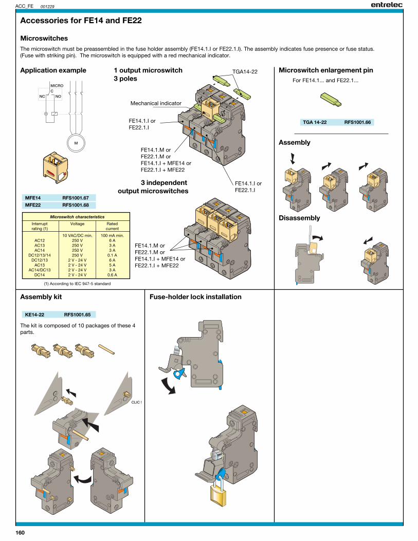
160
001229
TGA 14-22 RFS1001.66
ACC_FE
MFE14 RFS1001.67
MFE22 RFS1001.68
KE14-22 RFS1001.65
Accessories for FE14 and FE22
Microswitches
Assembly
Disassembly
Application example 1 output microswitch3 poles
Microswitch enlargement pin
Assembly kit Fuse-holder lock installation
Mechanical indicator
The microswitch must be preassembled in the fuse holder assembly (FE14.1.I or FE22.1.I). The assembly indicates fuse presence or fuse status.(Fuse with striking pin). The microswitch is equipped with a red mechanical indicator.
3 independentoutput microswitches
FE14.1.I orFE22.1.I
FE14.1.I orFE22.1.I
FE14.1.M orFE22.1.M orFE14.1.I + MFE14 orFE22.1.I + MFE22
TGA14-22
FE14.1.M orFE22.1.M orFE14.1.I + MFE14 orFE22.1.I + MFE22
For FE14.1... and FE22.1...
The kit is composed of 10 packages of these 4parts.
Microswitch characteristics
Interrupt Voltage Ratedrating (1) current
10 VAC/DC min. 100 mA min.AC12 250 V 6 AAC13 250 V 3 AAC14 250 V 3 A
DC12/13/14 250 V 0.1 ADC12/13 2 V - 24 V 6 A
AC13 2 V - 24 V 5 AAC14/DC13 2 V - 24 V 3 A
DC14 2 V - 24 V 0.6 A
(1) According to IEC 947-5 standard

161
IEC UL CSApending pending
IEC UL CSApending pending
IEC UL CSApending pending
IEC UL CSApending pending
12 mm / .47"1.2 Nm / 10.6 Ib.in
600 60030 30
6 mm2 6 AWG 6 AWG
0.5-1620-6 AWG 20-6 AWG
0.5-10A5
FECC.1 8711 618.02FECC.1 8711 618.21FECC.1 8711 618.22
FECC.2 8712 618.02 FECC.3 8713 618.02
FECC.1 FECC.2 FECC.3 FECC.4
FECC.4 8714 618.02
RC55 - RC510 RC55 - RC510RC55 - RC510RC55 - RC510
FT1 0399 371.13KE8-10 0206 125.24PCP.1.12 RAU8970 452.12PCP.1.13 RAU8970 452.13PCP.1.57 RAU8970 452.57PCP.2.12 RAU8970 453.12PCP.2.60 RAU8970 453.60PCP.3.12 RAU8970 454.12PCP.3.60 RAU8970 454.60PCP.4.12 RAU8970 455.12PCP.4.60 RAU8970 455.60BTVP15 RAU8970 460.01BTVP30 RAU8970 460.02
001229
3.1
"
R
1
4
2
3
FECC
FT1 0399 371.13KE8-10 0206 125.24PCP.1.12 RAU8970 452.12PCP.1.13 RAU8970 452.13PCP.1.57 RAU8970 452.57PCP.2.12 RAU8970 453.12PCP.2.60 RAU8970 453.60PCP.3.12 RAU8970 454.12PCP.3.60 RAU8970 454.60PCP.4.12 RAU8970 455.12PCP.4.60 RAU8970 455.60BTVP15 RAU8970 460.01BTVP30 RAU8970 460.02
FT1 0399 371.13KE8-10 0206 125.24PCP.1.12 RAU8970 452.12PCP.1.13 RAU8970 452.13PCP.1.57 RAU8970 452.57PCP.2.12 RAU8970 453.12PCP.2.60 RAU8970 453.60PCP.3.12 RAU8970 454.12PCP.3.60 RAU8970 454.60PCP.4.12 RAU8970 455.12PCP.4.60 RAU8970 455.60BTVP15 RAU8970 460.01BTVP30 RAU8970 460.02
12 mm / .47"1.2 Nm / 10.6 Ib.in
600 60030 30
6 mm2 6 AWG 6 AWG
0.5-1620-6 AWG 20-6 AWG
0.5-10A5
12 mm / .47"1.2 Nm / 10.6 Ib.in
600 60030 30
6 mm2 6 AWG 6 AWG
0.5-1620-6 AWG 20-6 AWG
0.5-10A5
12 mm / .47"1.2 Nm / 10.6 Ib.in
600 60030 30
6 mm2 6 AWG 6 AWG
0.5-1620-6 AWG 20-6 AWG
0.5-10A5
FT1 0399 371.13KE8-10 0206 125.24PCP.1.12 RAU8970 452.12PCP.1.13 RAU8970 452.13PCP.1.57 RAU8970 452.57PCP.2.12 RAU8970 453.12PCP.2.60 RAU8970 453.60PCP.3.12 RAU8970 454.12PCP.3.60 RAU8970 454.60PCP.4.12 RAU8970 455.12PCP.4.60 RAU8970 455.60BTVP15 RAU8970 460.01BTVP30 RAU8970 460.02
Rail 35 x 7.5 x 1 PR30 prepunched 0164 800.03Rail 35 x 15 x 2.3 PR4 0168 500.12Rail 35 x 15 x 1.5 PR5 prepunched 0101 598.26 1 pole
Modular fuse-holderfor CC fuses
DIN 3
2 poles 3 poles
Type P/N Type P/N Type P/N
Rated voltage V AC ~/= DCRated current ARated wire size mm² / AWGWire stripping length mm / inchesRecommended torque Nm / Ib.in
Characteristics
Type P/N
Solid wireStranded wireGauge
Wire size
mm2 AWG
StandardWith blown-fuse indicator 24-48 AC/DC / 48-115 VACWith blown-fuse indicator 115-690 VAC
Reference4 poles
1 Plate mounting kit2 Assembly Kit multipolar3 Flat pin jumper bar unipolar
63 A unipolarisolated IP20 unipolar(see accessories, bipolarpage 154) bipolar
tripolartripolar
tetrapolartetrapolar
4 Flat pin terminal 15 mm(25 mm²) 30 mm
R See section on markers
Type P/N Type P/N Type P/N Type P/NAccessories
IP20 protectionStandards : IEC 947-3 / 269-2
Blown fuse-indicator leakage current :< 0,5 mA at 24 V< 1 mA at 48 V< 2,5 mA at other voltages
The assembly of more than 3 modular fuse-holders equipped with fuses could downgraderated current. Consult us.
Spacing 17,6 mm (0.69")1 module
Spacing 35,2 mm (1.39")2 modules
Spacing 52,2 mm (2.08")3 modules
Spacing 70,4 mm (2.77")4 modules
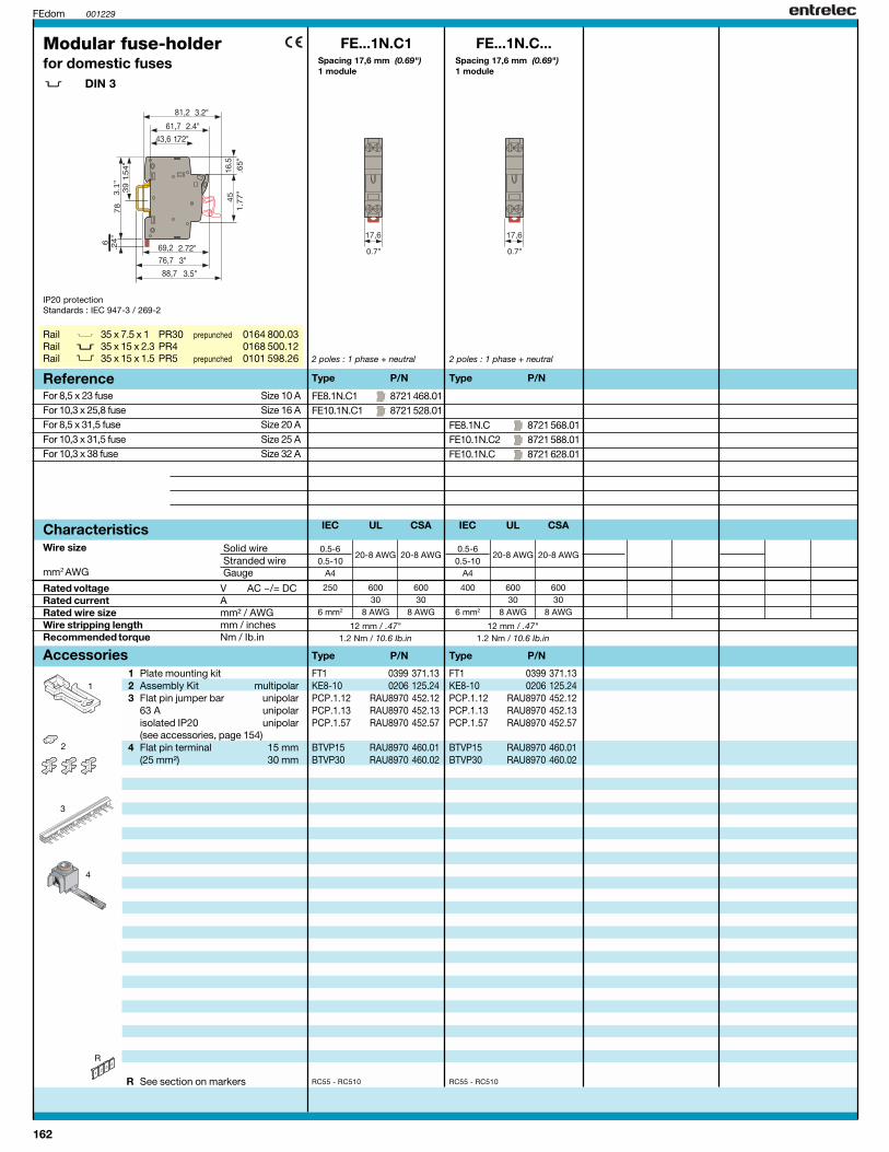
162
IEC UL CSA
12 mm / .47"1.2 Nm / 10.6 Ib.in
250 600 60030 30
6 mm2 8 AWG 8 AWG
0.5-620-8 AWG 20-8 AWG
0.5-10A4
FE8.1N.C1 8721 468.01FE10.1N.C1 8721 528.01
FE...1N.C1
RC55 - RC510
FT1 0399 371.13KE8-10 0206 125.24PCP.1.12 RAU8970 452.12PCP.1.13 RAU8970 452.13PCP.1.57 RAU8970 452.57
BTVP15 RAU8970 460.01BTVP30 RAU8970 460.02
001229
3.1
"
R
1
4
2
3
FEdom
IEC UL CSA
12 mm / .47"1.2 Nm / 10.6 Ib.in
400 600 60030 30
6 mm2 8 AWG 8 AWG
0.5-620-8 AWG 20-8 AWG
0.5-10A4
FE8.1N.C 8721 568.01FE10.1N.C2 8721 588.01FE10.1N.C 8721 628.01
FE...1N.C...
RC55 - RC510
FT1 0399 371.13KE8-10 0206 125.24PCP.1.12 RAU8970 452.12PCP.1.13 RAU8970 452.13PCP.1.57 RAU8970 452.57
BTVP15 RAU8970 460.01BTVP30 RAU8970 460.02
Rail 35 x 7.5 x 1 PR30 prepunched 0164 800.03Rail 35 x 15 x 2.3 PR4 0168 500.12Rail 35 x 15 x 1.5 PR5 prepunched 0101 598.26
Spacing 17,6 mm (0.69")1 module
2 poles : 1 phase + neutral
Modular fuse-holderfor domestic fuses
DIN 3
Rated voltage V AC ~/= DCRated current ARated wire size mm² / AWGWire stripping length mm / inchesRecommended torque Nm / Ib.in
Characteristics
Type P/N
Solid wireStranded wireGauge
Wire size
mm2 AWG
Reference
1 Plate mounting kit2 Assembly Kit multipolar3 Flat pin jumper bar unipolar
63 A unipolarisolated IP20 unipolar(see accessories, page 154)
4 Flat pin terminal 15 mm(25 mm²) 30 mm
R See section on markers
Type P/NAccessories
IP20 protectionStandards : IEC 947-3 / 269-2
For 8,5 x 23 fuse Size 10 AFor 10,3 x 25,8 fuse Size 16 AFor 8,5 x 31,5 fuse Size 20 AFor 10,3 x 31,5 fuse Size 25 AFor 10,3 x 38 fuse Size 32 A
Spacing 17,6 mm (0.69")1 module
2 poles : 1 phase + neutral
Type P/N
Type P/N

163
NOTES

164
IEC UL CSA IEC UL CSA IEC UL CSA IEC UL CSA
12 mm / .47"1.2 Nm / 10.6 Ib.in
400 300 30020 30 30
6 mm2 6 AWG 6 AWG
0.5-1620-6 AWG 20-6 AWG
0.5-10A5
FB8.1 8711 568.05FB8.1 8711 568.51FB8.1 8711 568.52
FB8-10.N 8711 627.04 FB8.1N 8715 568.05
FB8.1N 8715 568.52
FB8.1 FB8-10.N FB8.1N FB8.2
FB8.2 8712 568.05
RC55 - RC510 RC55 - RC510RC55 - RC510RC55 - RC510
FT1 0399 371.13KE8-10 0206 125.24PCP.1.12 RAU8970 452.12PCP.1.13 RAU8970 452.13PCP.1.57 RAU8970 452.57PCP.2.12 RAU8970 453.12PCP.2.60 RAU8970 453.60PCP.3.12 RAU8970 454.12PCP.3.60 RAU8970 454.60PCP.4.12 RAU8970 455.12PCP.4.60 RAU8970 455.60PCF.1.12 RAU8970 456.12PCF.1.57 RAU8970 456.57PCF.2.12 RAU8970 457.12PCF.2.60 RAU8970 457.60PCF.3.12 RAU8970 458.12PCF.3.60 RAU8970 458.60PCF.4.12 RAU8970 459.12PCF.4.60 RAU8970 459.60FU853
BTVP15 RAU8970 460.01BTVP30 RAU8970 460.02BTVF15 RAU8970 461.01BTVF30 RAU8970 461.02
001229
3.1
"
R
1
5
2
3
6
FB8-1
12 mm / .47"1.2 Nm / 10.6 Ib.in
690 300 30032 30 30
6 mm2 6 AWG 6 AWG
0.5-1620-6 AWG 20-6 AWG
0.5-10A5
12 mm / .47"1.2 Nm / 10.6 Ib.in
400 300 30020 30 30
6 mm2 6 AWG 6 AWG
0.5-1620-6 AWG 20-6 AWG
0.5-10A5
12 mm / .47"1.2 Nm / 10.6 Ib.in
400 300 30020 30 30
6 mm2 6 AWG 6 AWG
0.5-1620-6 AWG 20-6 AWG
0.5-10A5
4
7
FT1 0399 371.13KE8-10 0206 125.24PCP.1.12 RAU8970 452.12PCP.1.13 RAU8970 452.13PCP.1.57 RAU8970 452.57PCP.2.12 RAU8970 453.12PCP.2.60 RAU8970 453.60PCP.3.12 RAU8970 454.12PCP.3.60 RAU8970 454.60PCP.4.12 RAU8970 455.12PCP.4.60 RAU8970 455.60PCF.1.12 RAU8970 456.12PCF.1.57 RAU8970 456.57PCF.2.12 RAU8970 457.12PCF.2.60 RAU8970 457.60PCF.3.12 RAU8970 458.12PCF.3.60 RAU8970 458.60PCF.4.12 RAU8970 459.12PCF.4.60 RAU8970 459.60
BTVP15 RAU8970 460.01BTVP30 RAU8970 460.02BTVF15 RAU8970 461.01BTVF30 RAU8970 461.02
FT1 0399 371.13KE8-10 0206 125.24PCP.1.12 RAU8970 452.12PCP.1.13 RAU8970 452.13PCP.1.57 RAU8970 452.57PCP.2.12 RAU8970 453.12PCP.2.60 RAU8970 453.60PCP.3.12 RAU8970 454.12PCP.3.60 RAU8970 454.60PCP.4.12 RAU8970 455.12PCP.4.60 RAU8970 455.60PCF.1.12 RAU8970 456.12PCF.1.57 RAU8970 456.57PCF.2.12 RAU8970 457.12PCF.2.60 RAU8970 457.60PCF.3.12 RAU8970 458.12PCF.3.60 RAU8970 458.60PCF.4.12 RAU8970 459.12PCF.4.60 RAU8970 459.60FU853
BTVP15 RAU8970 460.01BTVP30 RAU8970 460.02BTVF15 RAU8970 461.01BTVF30 RAU8970 461.02
Rail 35 x 7.5 x 1 PR30 prepunched 0164 800.03Rail 35 x 15 x 2.3 PR4 0168 500.12Rail 35 x 15 x 1.5 PR5 prepunched 0101 598.26
Spacing 17,6 mm (0.69")1 module
1 pole
Dual connectionfuse-holderfor 8,5 x 31,5 mm 11/32 x 1 1/4 in. fuses
DIN 3
1 pole : neutral
Spacing 17,6 mm (0.69")1 module
Spacing 35,2 mm (1.39")2 modules
2 poles : 1 phase + neutral
Type P/N Type P/N Type P/N
Rated voltage V AC ~/= DCRated current ARated wire size mm² / AWGWire stripping length mm / inchesRecommended torque Nm / Ib.in
Characteristics
Type P/N
Solid wireStranded wireGauge
Wire size
mm2 AWG
StandardWith blown-fuse indicator 24-48 AC/DC / 48-115 VACWith blown-fuse indicator 115-690 VAC
Reference
Spacing 35,2 mm (1.39")2 modules
2 poles
1 Plate mounting kit2 Assembly Kit multipolar3 Flat pin jumper bar unipolar
63 A unipolarisolated IP20 unipolar(see accessories, bipolarpage 154) bipolar
tripolartripolar
tetrapolartetrapolar
4 Spade jumper bar unipolar63A unipolarisolated IP20 bipolar(see accessories, bipolarpage 154) tripolar
tripolartetrapolartetrapolar
5 8,5 x 31,5 mm fuses(see accessories, page 154)
6 Flat pin terminal 15 mm(25 mm²) 30 mm
7 Spade terminal 15 mm(25 mm²) 30 mm
R See section on markers
Type P/N Type P/N Type P/N Type P/NAccessories
IP20 protectionStandards : IEC 947-3 / 269-2
Blown fuse-indicator leakage current :< 0,5 mA at 24 V< 1 mA at 48 V< 2,5 mA at other voltages
The assembly of more than 3 modular fuse-holders equipped with fuses could downgraderated current. Consult us.
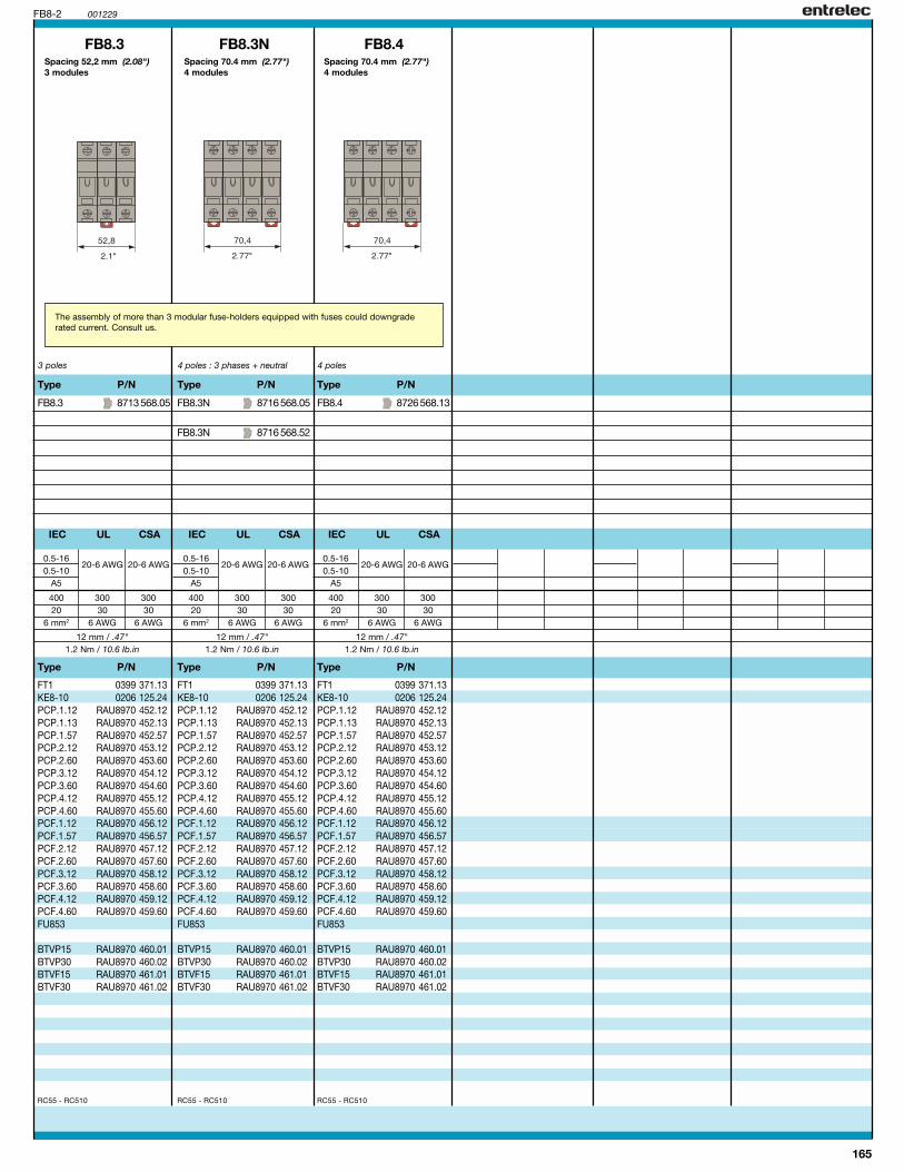
165
IEC UL CSA
12 mm / .47"1.2 Nm / 10.6 Ib.in
400 300 30020 30 30
6 mm2 6 AWG 6 AWG
0.5-1620-6 AWG 20-6 AWG
0.5-10A5
FB8.4 8726 568.13
FB8.4
RC55 - RC510
001229FB8-2
IEC UL CSA
12 mm / .47"1.2 Nm / 10.6 Ib.in
400 300 30020 30 30
6 mm2 6 AWG 6 AWG
0.5-1620-6 AWG 20-6 AWG
0.5-10A5
FB8.3 8713 568.05
FB8.3
RC55 - RC510
IEC UL CSA
12 mm / .47"1.2 Nm / 10.6 Ib.in
400 300 30020 30 30
6 mm2 6 AWG 6 AWG
0.5-1620-6 AWG 20-6 AWG
0.5-10A5
FB8.3N 8716 568.05
FB8.3N 8716 568.52
FB8.3N
RC55 - RC510
FT1 0399 371.13KE8-10 0206 125.24PCP.1.12 RAU8970 452.12PCP.1.13 RAU8970 452.13PCP.1.57 RAU8970 452.57PCP.2.12 RAU8970 453.12PCP.2.60 RAU8970 453.60PCP.3.12 RAU8970 454.12PCP.3.60 RAU8970 454.60PCP.4.12 RAU8970 455.12PCP.4.60 RAU8970 455.60PCF.1.12 RAU8970 456.12PCF.1.57 RAU8970 456.57PCF.2.12 RAU8970 457.12PCF.2.60 RAU8970 457.60PCF.3.12 RAU8970 458.12PCF.3.60 RAU8970 458.60PCF.4.12 RAU8970 459.12PCF.4.60 RAU8970 459.60FU853
BTVP15 RAU8970 460.01BTVP30 RAU8970 460.02BTVF15 RAU8970 461.01BTVF30 RAU8970 461.02
Spacing 70.4 mm (2.77")4 modules
4 poles
Type P/N
Type P/N
The assembly of more than 3 modular fuse-holders equipped with fuses could downgraderated current. Consult us.
Spacing 52,2 mm (2.08")3 modules
3 poles
Type P/N
Type P/N
Spacing 70.4 mm (2.77")4 modules
4 poles : 3 phases + neutral
Type P/N
Type P/N
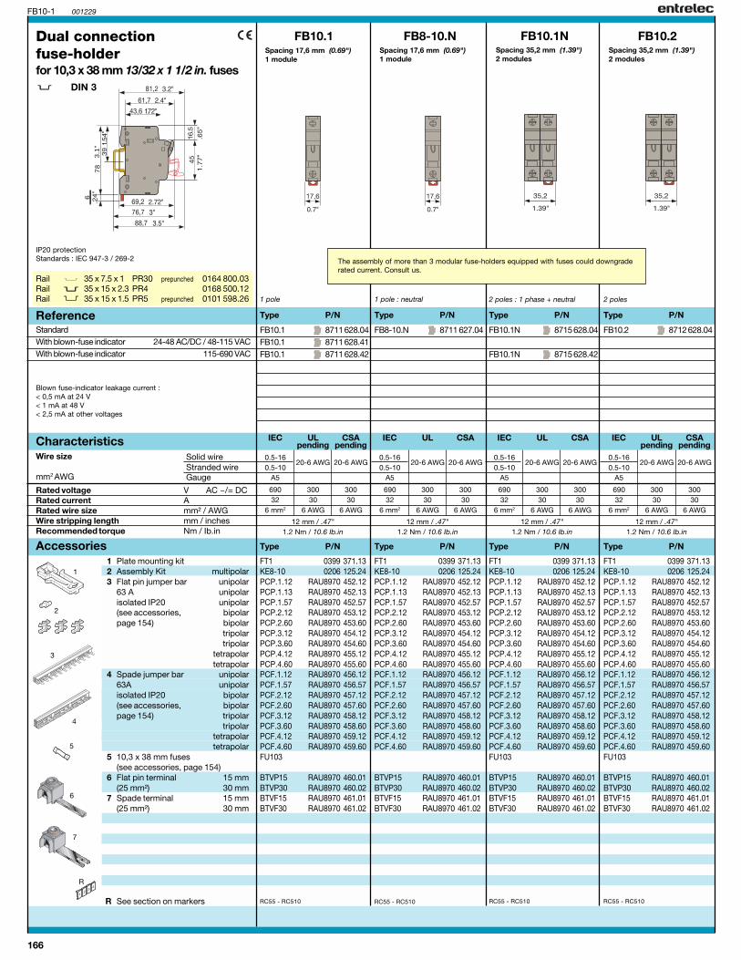
166
IEC UL CSApending pending
IEC UL CSA IEC UL CSA IEC UL CSApending pending
12 mm / .47"1.2 Nm / 10.6 Ib.in
690 300 30032 30 30
6 mm2 6 AWG 6 AWG
0.5-1620-6 AWG 20-6 AWG
0.5-10A5
FB10.1 8711 628.04FB10.1 8711 628.41FB10.1 8711 628.42
FB8-10.N 8711 627.04 FB10.1N 8715 628.04
FB10.1N 8715 628.42
FB10.1 FB8-10.N FB10.1N FB10.2
FB10.2 8712 628.04
RC55 - RC510 RC55 - RC510RC55 - RC510RC55 - RC510
FT1 0399 371.13KE8-10 0206 125.24PCP.1.12 RAU8970 452.12PCP.1.13 RAU8970 452.13PCP.1.57 RAU8970 452.57PCP.2.12 RAU8970 453.12PCP.2.60 RAU8970 453.60PCP.3.12 RAU8970 454.12PCP.3.60 RAU8970 454.60PCP.4.12 RAU8970 455.12PCP.4.60 RAU8970 455.60PCF.1.12 RAU8970 456.12PCF.1.57 RAU8970 456.57PCF.2.12 RAU8970 457.12PCF.2.60 RAU8970 457.60PCF.3.12 RAU8970 458.12PCF.3.60 RAU8970 458.60PCF.4.12 RAU8970 459.12PCF.4.60 RAU8970 459.60FU103
BTVP15 RAU8970 460.01BTVP30 RAU8970 460.02BTVF15 RAU8970 461.01BTVF30 RAU8970 461.02
001229
3.1
"
R
1
5
2
3
6
FB10-1
12 mm / .47"1.2 Nm / 10.6 Ib.in
690 300 30032 30 30
6 mm2 6 AWG 6 AWG
0.5-1620-6 AWG 20-6 AWG
0.5-10A5
12 mm / .47"1.2 Nm / 10.6 Ib.in
690 300 30032 30 30
6 mm2 6 AWG 6 AWG
0.5-1620-6 AWG 20-6 AWG
0.5-10A5
12 mm / .47"1.2 Nm / 10.6 Ib.in
690 300 30032 30 30
6 mm2 6 AWG 6 AWG
0.5-1620-6 AWG 20-6 AWG
0.5-10A5
4
7
FT1 0399 371.13KE8-10 0206 125.24PCP.1.12 RAU8970 452.12PCP.1.13 RAU8970 452.13PCP.1.57 RAU8970 452.57PCP.2.12 RAU8970 453.12PCP.2.60 RAU8970 453.60PCP.3.12 RAU8970 454.12PCP.3.60 RAU8970 454.60PCP.4.12 RAU8970 455.12PCP.4.60 RAU8970 455.60PCF.1.12 RAU8970 456.12PCF.1.57 RAU8970 456.57PCF.2.12 RAU8970 457.12PCF.2.60 RAU8970 457.60PCF.3.12 RAU8970 458.12PCF.3.60 RAU8970 458.60PCF.4.12 RAU8970 459.12PCF.4.60 RAU8970 459.60
BTVP15 RAU8970 460.01BTVP30 RAU8970 460.02BTVF15 RAU8970 461.01BTVF30 RAU8970 461.02
FT1 0399 371.13KE8-10 0206 125.24PCP.1.12 RAU8970 452.12PCP.1.13 RAU8970 452.13PCP.1.57 RAU8970 452.57PCP.2.12 RAU8970 453.12PCP.2.60 RAU8970 453.60PCP.3.12 RAU8970 454.12PCP.3.60 RAU8970 454.60PCP.4.12 RAU8970 455.12PCP.4.60 RAU8970 455.60PCF.1.12 RAU8970 456.12PCF.1.57 RAU8970 456.57PCF.2.12 RAU8970 457.12PCF.2.60 RAU8970 457.60PCF.3.12 RAU8970 458.12PCF.3.60 RAU8970 458.60PCF.4.12 RAU8970 459.12PCF.4.60 RAU8970 459.60FU103
BTVP15 RAU8970 460.01BTVP30 RAU8970 460.02BTVF15 RAU8970 461.01BTVF30 RAU8970 461.02
Rail 35 x 7.5 x 1 PR30 prepunched 0164 800.03Rail 35 x 15 x 2.3 PR4 0168 500.12Rail 35 x 15 x 1.5 PR5 prepunched 0101 598.26
Spacing 17,6 mm (0.69")1 module
1 pole
Dual connectionfuse-holderfor 10,3 x 38 mm 13/32 x 1 1/2 in. fuses
DIN 3
1 pole : neutral
Spacing 17,6 mm (0.69")1 module
Spacing 35,2 mm (1.39")2 modules
2 poles : 1 phase + neutral
Type P/N Type P/N Type P/N
Rated voltage V AC ~/= DCRated current ARated wire size mm² / AWGWire stripping length mm / inchesRecommended torque Nm / Ib.in
Characteristics
Type P/N
Solid wireStranded wireGauge
Wire size
mm2 AWG
StandardWith blown-fuse indicator 24-48 AC/DC / 48-115 VACWith blown-fuse indicator 115-690 VAC
Reference
Spacing 35,2 mm (1.39")2 modules
2 poles
1 Plate mounting kit2 Assembly Kit multipolar3 Flat pin jumper bar unipolar
63 A unipolarisolated IP20 unipolar(see accessories, bipolarpage 154) bipolar
tripolartripolar
tetrapolartetrapolar
4 Spade jumper bar unipolar63A unipolarisolated IP20 bipolar(see accessories, bipolarpage 154) tripolar
tripolartetrapolartetrapolar
5 10,3 x 38 mm fuses(see accessories, page 154)
6 Flat pin terminal 15 mm(25 mm²) 30 mm
7 Spade terminal 15 mm(25 mm²) 30 mm
R See section on markers
Type P/N Type P/N Type P/N Type P/NAccessories
IP20 protectionStandards : IEC 947-3 / 269-2
Blown fuse-indicator leakage current :< 0,5 mA at 24 V< 1 mA at 48 V< 2,5 mA at other voltages
The assembly of more than 3 modular fuse-holders equipped with fuses could downgraderated current. Consult us.

167
IEC UL CSApending pending
12 mm / .47"1.2 Nm / 10.6 Ib.in
690 300 30032 30 30
6 mm2 6 AWG 6 AWG
0.5-1620-6 AWG 20-6 AWG
0.5-10A5
FB10.4 8714 628.04
FB10.4
RC55 - RC510
001229FB10-2
IEC UL CSApending pending
12 mm / .47"1.2 Nm / 10.6 Ib.in
690 300 30032 30 30
6 mm2 6 AWG 6 AWG
0.5-1620-6 AWG 20-6 AWG
0.5-10A5
FB10.3 8713 628.04
FB10.3
RC55 - RC510
IEC UL CSA
12 mm / .47"1.2 Nm / 10.6 Ib.in
690 300 30032 30 30
6 mm2 6 AWG 6 AWG
0.5-1620-6 AWG 20-6 AWG
0.5-10A5
FB10.3N 8716 628.04
FB10.3N 8716 628.42
FB10.3N
RC55 - RC510
FT1 0399 371.13KE8-10 0206 125.24PCP.1.12 RAU8970 452.12PCP.1.13 RAU8970 452.13PCP.1.57 RAU8970 452.57PCP.2.12 RAU8970 453.12PCP.2.60 RAU8970 453.60PCP.3.12 RAU8970 454.12PCP.3.60 RAU8970 454.60PCP.4.12 RAU8970 455.12PCP.4.60 RAU8970 455.60PCF.1.12 RAU8970 456.12PCF.1.57 RAU8970 456.57PCF.2.12 RAU8970 457.12PCF.2.60 RAU8970 457.60PCF.3.12 RAU8970 458.12PCF.3.60 RAU8970 458.60PCF.4.12 RAU8970 459.12PCF.4.60 RAU8970 459.60FU103
BTVP15 RAU8970 460.01BTVP30 RAU8970 460.02BTVF15 RAU8970 461.01BTVF30 RAU8970 461.02
Spacing 70.4 mm (2.77")4 modules
4 poles
Type P/N
Type P/N
The assembly of more than 3 modular fuse-holders equipped with fuses could downgraderated current. Consult us.
Spacing 52,2 mm (2.08")3 modules
3 poles
Type P/N
Type P/N
Spacing 70.4 mm (2.77")4 modules
4 poles : 3 phases + neutral
Type P/N
Type P/N
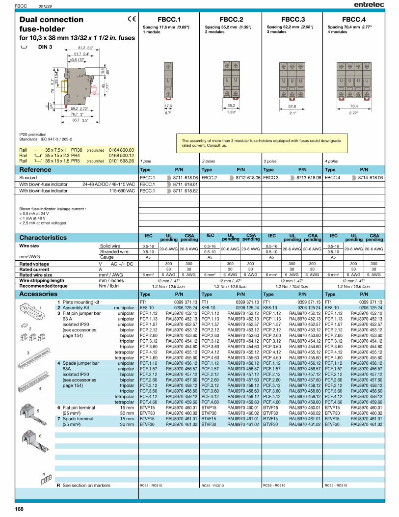
168
IEC UL CSApending pending
IEC UL CSApending pending
IEC UL CSApending pending
IEC UL CSApending pending
12 mm / .47"1.2 Nm / 10.6 Ib.in
300 30030 30
6 mm2 6 AWG 6 AWG
0.5-1620-6 AWG 20-6 AWG
0.5-10A5
FBCC.1 8711 618.06FBCC.1 8711 618.61FBCC.1 8711 618.62
FBCC.2 8712 618.06 FBCC.3 8713 618.06
FBCC.1 FBCC.2 FBCC.3 FBCC.4
FBCC.4 8714 618.06
RC55 - RC510 RC55 - RC510RC55 - RC510RC55 - RC510
FT1 0399 371.13KE8-10 0206 125.24PCP.1.12 RAU8970 452.12PCP.1.13 RAU8970 452.13PCP.1.57 RAU8970 452.57PCP.2.12 RAU8970 453.12PCP.2.60 RAU8970 453.60PCP.3.12 RAU8970 454.12PCP.3.60 RAU8970 454.60PCP.4.12 RAU8970 455.12PCP.4.60 RAU8970 455.60PCF.1.12 RAU8970 456.12PCF.1.57 RAU8970 456.57PCF.2.12 RAU8970 457.12PCF.2.60 RAU8970 457.60PCF.3.12 RAU8970 458.12PCF.3.60 RAU8970 458.60PCF.4.12 RAU8970 459.12PCF.4.60 RAU8970 459.60BTVP15 RAU8970 460.01BTVP30 RAU8970 460.02BTVF15 RAU8970 461.01BTVF30 RAU8970 461.02
001229
3.1
"
R
1
5
2
3
FBCC
12 mm / .47"1.2 Nm / 10.6 Ib.in
300 30030 30
6 mm2 6 AWG 6 AWG
0.5-1620-6 AWG 20-6 AWG
0.5-10A5
12 mm / .47"1.2 Nm / 10.6 Ib.in
300 30030 30
6 mm2 6 AWG 6 AWG
0.5-1620-6 AWG 20-6 AWG
0.5-10A5
12 mm / .47"1.2 Nm / 10.6 Ib.in
300 30030 30
6 mm2 6 AWG 6 AWG
0.5-1620-6 AWG 20-6 AWG
0.5-10A5
4
6
FT1 0399 371.13KE8-10 0206 125.24PCP.1.12 RAU8970 452.12PCP.1.13 RAU8970 452.13PCP.1.57 RAU8970 452.57PCP.2.12 RAU8970 453.12PCP.2.60 RAU8970 453.60PCP.3.12 RAU8970 454.12PCP.3.60 RAU8970 454.60PCP.4.12 RAU8970 455.12PCP.4.60 RAU8970 455.60PCF.1.12 RAU8970 456.12PCF.1.57 RAU8970 456.57PCF.2.12 RAU8970 457.12PCF.2.60 RAU8970 457.60PCF.3.12 RAU8970 458.12PCF.3.60 RAU8970 458.60PCF.4.12 RAU8970 459.12PCF.4.60 RAU8970 459.60BTVP15 RAU8970 460.01BTVP30 RAU8970 460.02BTVF15 RAU8970 461.01BTVF30 RAU8970 461.02
FT1 0399 371.13KE8-10 0206 125.24PCP.1.12 RAU8970 452.12PCP.1.13 RAU8970 452.13PCP.1.57 RAU8970 452.57PCP.2.12 RAU8970 453.12PCP.2.60 RAU8970 453.60PCP.3.12 RAU8970 454.12PCP.3.60 RAU8970 454.60PCP.4.12 RAU8970 455.12PCP.4.60 RAU8970 455.60PCF.1.12 RAU8970 456.12PCF.1.57 RAU8970 456.57PCF.2.12 RAU8970 457.12PCF.2.60 RAU8970 457.60PCF.3.12 RAU8970 458.12PCF.3.60 RAU8970 458.60PCF.4.12 RAU8970 459.12PCF.4.60 RAU8970 459.60BTVP15 RAU8970 460.01BTVP30 RAU8970 460.02BTVF15 RAU8970 461.01BTVF30 RAU8970 461.02
FT1 0399 371.13KE8-10 0206 125.24PCP.1.12 RAU8970 452.12PCP.1.13 RAU8970 452.13PCP.1.57 RAU8970 452.57PCP.2.12 RAU8970 453.12PCP.2.60 RAU8970 453.60PCP.3.12 RAU8970 454.12PCP.3.60 RAU8970 454.60PCP.4.12 RAU8970 455.12PCP.4.60 RAU8970 455.60PCF.1.12 RAU8970 456.12PCF.1.57 RAU8970 456.57PCF.2.12 RAU8970 457.12PCF.2.60 RAU8970 457.60PCF.3.12 RAU8970 458.12PCF.3.60 RAU8970 458.60PCF.4.12 RAU8970 459.12PCF.4.60 RAU8970 459.60BTVP15 RAU8970 460.01BTVP30 RAU8970 460.02BTVF15 RAU8970 461.01BTVF30 RAU8970 461.02
Rail 35 x 7.5 x 1 PR30 prepunched 0164 800.03Rail 35 x 15 x 2.3 PR4 0168 500.12Rail 35 x 15 x 1.5 PR5 prepunched 0101 598.26 1 pole
Dual connectionfuse-holderfor 10,3 x 38 mm 13/32 x 1 1/2 in. fuses
DIN 3
2 poles 3 poles
Type P/N Type P/N Type P/N
Rated voltage V AC ~/= DCRated current ARated wire size mm² / AWGWire stripping length mm / inchesRecommended torque Nm / Ib.in
Characteristics
Type P/N
Solid wireStranded wireGauge
Wire size
mm2 AWG
StandardWith blown-fuse indicator 24-48 AC/DC / 48-115 VACWith blown-fuse indicator 115-690 VAC
Reference4 poles
1 Plate mounting kit2 Assembly Kit multipolar3 Flat pin jumper bar unipolar
63 A unipolarisolated IP20 unipolar(see accessories, bipolarpage 154) bipolar
tripolartripolar
tetrapolartetrapolar
4 Spade jumper bar unipolar63A unipolarisolated IP20 bipolar(see accessories bipolarpage 154) tripolar
tripolartetrapolartetrapolar
6 Flat pin terminal 15 mm(25 mm²) 30 mm
7 Spade terminal 15 mm(25 mm²) 30 mm
R See section on markers
Type P/N Type P/N Type P/N Type P/NAccessories
IP20 protectionStandards : IEC 947-3 / 269-2
Blown fuse-indicator leakage current :< 0,5 mA at 24 V< 1 mA at 48 V< 2,5 mA at other voltages
The assembly of more than 3 modular fuse-holders equipped with fuses could downgraderated current. Consult us.
Spacing 17,6 mm (0.69")1 module
Spacing 35,2 mm (1.39")2 modules
Spacing 52,2 mm (2.08")3 modules
Spacing 70,4 mm 2.77"4 modules

169
0107T 001222
Terminal blocks forrailway rolling stock
Request ourRailway Rolling Stockcatalog.
170
NOTES

171
0,5-4 mm² 22-12 AWG 22-12 AWG0,5-4 mm² 22-12 AWG 22-12 AWG
500 V Gr.C 600 V 300 V
26 A 20 A 20 A
4 mm² / A4 12 AWG 12 AWG
0,5-4 mm² 22-12 AWG 22-12 AWG0,5-4 mm² 22-12 AWG 22-12 AWG
500 V Gr.C 600 V 300 V
26 A 20 A 20 A
4 mm² / A4 12 AWG 12 AWG
NFC DIN UL CSA NFC DIN UL CSA
M 4/6.DE...
T01093 001229
8,5 mm 4 mm 0.5-0.6 Nm IP20.33" .157" 4.4-5.3 lb.in NEMA 1
FEM6D 1,0 mm 0118 499.23FEM6D 1,0 mm 0128 499.25SCF6D 1,0 mm 0118 495.17AL2 2,0 mm 0163 070.00AL3 3,0 mm 0163 261.00DCG 0163 218.05FC2 (2) 2,0 mm 0007 865.26BJM6D (1)(3) 2 0173 515.11BJM6D (1)(3) 3 0173 516.12BJM6D (1)(3) 4 0173 517.13BJM6D (1)(3) 5 0173 519.25BJM6D (1)(3) 10 0173 520.22BJMI6D (1)(3) 2 0179 668.20BJMI6D (1)(3) 3 0179 669.21BJMI6D (1)(3) 4 0179 670.26BJMI6D (1)(3) 5 0179 671.13BJMI6D (1)(3) 10 0179 672.14EL6 (1)(3) 0173 627.21BJS61 (1)(3) 10 0168 485.27EV6D 0168 400.16PC61 0,5 mm 10 0163 311.22AD2,5 0114 205.20
11 12
M 4/6.DE 0115 185.05M 4/6.DEN 0125 185.07
M 4/6.DE1
2
4
3
8
FEM6D 1,0 mm 0118 499.23
SCF6D 1,0 mm 0118 495.17AL2 2,0 mm 0163 070.00AL3 3,0 mm 0163 261.00DCG 0163 218.05FC2 (2) 2,0 mm 0007 865.26BJM6D (1) 2 0173 515.11BJM6D (1) 3 0173 516.12BJM6D (1) 4 0173 517.13BJM6D (1) 5 0173 519.25BJM6D (1) 10 0173 520.22BJMI6D (1) 2 0179 668.20BJMI6D (1) 3 0179 669.21BJMI6D (1) 4 0179 670.26BJMI6D (1) 5 0179 671.13BJMI6D (1) 10 0179 672.14EL6 (1) 0173 627.21BJS61 (1) 10 0168 485.27EV6D 0168 400.16PC61 0,5 mm 10 0163 311.22AD2,5 0114 205.20
11 12
9
10
M 4/6.DE1 0115 177.14
8,5 mm 4 mm 0.5-0.6 Nm IP20.33" .157" 4.4-5.3 lb.in NEMA 1
1
65
7
R
BAMH 0114 836.00
35 x 7,5 x 135 x 15 x 2,3 PR4 0168 500.1235 x 15 x 1,532 x 15 PR1Z2 0163 050.04
End stop th. 9,1 mmOther end stops : See Accessories sectionRail PR30 prepunched0173 220.05RailRail PR5 prepunched0101 598.26RailOther rails : See Accessories section
Component holderterminal blocksEmpty blocksBlocks with LED indicatorDouble deck blocksCompression clamp
DIN 1 - 3
Spacing 6 mm +0,05 (.238")
1 End section greyblue
2 Separator end section grey3 Test socket
4 Test device grey5 Test plug6 Assembled 32 A
jumper bar 32 A(without IP 20 protection) 32 A
32 A32 A
Assembled 32 Ajumper bar 32 A(with IP 20 protection) 32 A
32 A32 A
7 Connector bar 35 A8 Jumper bar not assembled 32 A
Screw + post + washer9 Comb-type jumper bar 35 A
10 IDC jumper 24 A
R See section on markersmarking method
Spacing 6 mm +0,05 (.238")
Note : (1) Use of these accessories requires the user to cut out the partition.(2) For block equipped with AL2 or DCG.(3) These accessories can be used on the lower connection only.
Empty blocks for components (th. 5 mm max.).Internal, soldered connections, external, by compression clamp.
Empty blocks for components (th. 5 mm max.).Internal, soldered connections, external, by compression clamp.
th.th.th.
DIA.DIA.
DIA.polespolespolespolespolespolespolespolespolespoles
poles
th. poles
Sides of block Top of block
Upper and lower circuit openedGreyBlue
th.
th.DIA.DIA.
DIA.polespolespolespolespolespolespolespolespolespoles
poles
th. poles
Sides of block Top of block
Lower circuit openedGrey
Color Type Part numbers Color Type Part numbers
Characteristics Characteristics
Type Part numbers
Rated
Rated / Gauge
Wire size
Current
Wire size
Notes
Type Part numbers
Rated
Rated / Gauge
Wire size
Current
Wire size
Accessories
Compression Solid wire
clamp Stranded wire
RatedPulsePollution degree
VoltageRatedPulsePollution degree
Compression Solid wire
clamp Stranded wire
Voltage
The use of some accessories may decrease the block'svoltage rating. For more information, consult us.
Wire stripping Recomm. Recomm. Protectionlength screwdriver torque
Wire stripping Recomm. Recomm. Protectionlength screwdriver torque
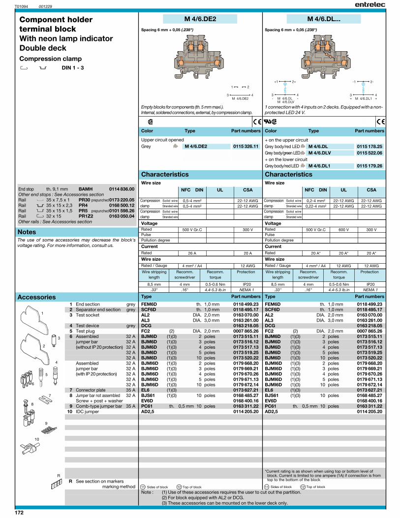
172
T01094 001229
BAMH 0114 836.00
35 x 7,5 x 135 x 15 x 2,3 PR4 0168 500.1235 x 15 x 1,532 x 15 PR1Z2 0163 050.04
0,5-4 mm² 22-12 AWG0,5-4 mm² 22-12 AWG
500 V Gr.C 300 V
26 A 20 A
4 mm² / A4 12 AWG
0,2-4 mm² 22-12 AWG 22-12 AWG0,22-4 mm² 22-12 AWG 22-12 AWG
500 V Gr.C 600 V 300 V
20 A* 20 A* 20 A*
4 mm² / A4 12 AWG 12 AWG
NFC DIN UL CSA NFC DIN UL CSA
M 4/6.DE2
8,5 mm 4 mm 0.5-0.6 Nm IP20.33" .16" 4.4-5.3 lb.in NEMA 1
FEM6D 1,0 mm 0118 499.23SCF6D 1,0 mm 0118 495.17AL2 2,0 mm 0163 070.00AL3 3,0 mm 0163 261.00DCG 0163 218.05FC2 (2) 2,0 mm 0007 865.26BJM6D (1)(3) 2 0173 515.11BJM6D (1)(3) 3 0173 516.12BJM6D (1)(3) 4 0173 517.13BJM6D (1)(3) 5 0173 519.25BJM6D (1)(3) 10 0173 520.22BJMI6D (1)(3) 2 0179 668.20BJMI6D (1)(3) 3 0179 669.21BJMI6D (1)(3) 4 0179 670.26BJMI6D (1)(3) 5 0179 671.13BJMI6D (1)(3) 10 0179 672.14EL6 (1)(3) 0173 627.21BJS61 (1)(3) 10 0168 485.27EV6D 0168 400.16PC61 0,5 mm 10 0163 311.22AD2,5 0114 205.20
11 12
M 4/6.DL...
8,5 mm 4 mm 0.5-0.6 Nm IP20.33" .16" 4.4-5.3 lb.in NEMA 1
FEM6D 1,0 mm 0118 499.23SCF6D 1,0 mm 0118 495.17AL2 2,0 mm 0163 070.00AL3 3,0 mm 0163 261.00DCG 0163 218.05FC2 (2) 2,0 mm 0007 865.26BJM6D (1)(3) 2 0173 515.11BJM6D (1)(3) 3 0173 516.12BJM6D (1)(3) 4 0173 517.13BJM6D (1)(3) 5 0173 519.25BJM6D (1)(3) 10 0173 520.22BJMI6D (1)(3) 2 0179 668.20BJMI6D (1)(3) 3 0179 669.21BJMI6D (1)(3) 4 0179 670.26BJMI6D (1)(3) 5 0179 671.13BJMI6D (1)(3) 10 0179 672.14EL6 (1)(3) 0173 627.21BJS61 (1)(3) 10 0168 485.27EV6D 0168 400.16PC61 0,5 mm 10 0163 311.22AD2,5 0114 205.20
11 12
M 4/6.DE2 0115 326.11 M 4/6.DL 0115 178.25M 4/6.DLV 0115 522.06
M 4/6.DL1 0115 179.26
5
2
4
3
7
8
6
9
10
R
1
End stop th. 9,1 mmOther end stops : See Accessories sectionRail PR30 prepunched0173 220.05RailRail PR5 prepunched0101 598.26RailOther rails : See Accessories section
Component holderterminal blockWith neon lamp indicatorDouble deckCompression clamp
DIN 1 - 3
1 End section grey2 Separator end section grey3 Test socket
4 Test device grey5 Test plug6 Assembled 32 A
jumper bar 32 A(without IP 20 protection) 32 A
32 A32 A
Assembled 32 Ajumper bar 32 A(with IP 20 protection) 32 A
32 A32 A
7 Connector plate 35 A8 Jumper bar not assembled 32 A
Screw + post + washer9 Comb-type jumper bar 35 A
10 IDC jumper
R See section on markersmarking method
Note : (1) Use of these accessories requires the user to cut out the partition.(2) For block equipped with AL2 or DCG.(3) These accessories can be mounted on the lower deck only.
Notes
Accessories
The use of some accessories may decrease the block'svoltage rating. For more information, consult us.
Spacing 6 mm + 0,05 (.238") Spacing 6 mm + 0,05 (.238")
Empty blocks for components (th. 5 mm maxi.).Internal, soldered connections, external, by compression clamp.
1 connection with 4 inputs on 2 decks. Equipped with a non-protected LED 24 V.
th.th.
DIA.DIA.
DIA.polespolespolespolespolespolespolespolespolespoles
poles
th. poles
Sides of block Top of block
th.th.
DIA.DIA.
DIA.polespolespolespolespolespolespolespolespolespoles
poles
th. poles
Sides of block Top of block
Upper circuit openedGrey
+ on the upper circuitGrey body/red LEDGrey body/green LED+ on the lower circuitGrey body/red LED
Color Type Part numbers
Characteristics
Type Part numbers
Rated
Rated / Gauge
Wire size
Current
Wire size
Compression Solid wire
clamp Stranded wire
Compression Solid wire
clamp Stranded wire
RatedPulsePollution degree
Voltage
Wire stripping Recomm. Recomm. Protectionlength screwdriver torque
Characteristics
Type Part numbers
Rated
Rated / Gauge
Wire size
Current
Wire size
Compression Solid wire
clamp Stranded wire
Compression Solid wire
clamp Stranded wire
RatedPulsePollution degree
Voltage
Wire stripping Recomm. Recomm. Protectionlength screwdriver torque
Color Type Part numbers
*Current rating is as shown when using top or bottom level of block. Current is limited to one ampere (1A) if connection is from top to the bottom of the block

173
0,2-4 mm² 22-12 AWG 18-12 AWG0,22-4 mm² 22-12 AWG 18-12 AWG
500 V Gr.C 600 V 150 V
20 A* 20 A* 25 A*
4 mm² / A4 12 AWG 12 AWG
NFC DIN UL CSA
T01095 001229
5
2
4
3
7
8
6
9
10
M 4/6.DN...
FEM6D 1,0 mm 0118 499.23SCF6D 1,0 mm 0118 495.17AL2 2,0 mm 0163 070.00AL3 3,0 mm 0163 261.00DCG 0163 218.05FC2 (2) 2,0 mm 0007 865.26BJM6D (1)(3) 2 0173 515.11BJM6D (1)(3) 3 0173 516.12BJM6D (1)(3) 4 0173 517.13BJM6D (1)(3) 5 0173 519.25BJM6D (1)(3) 10 0173 520.22BJMI6D (1)(3) 2 0179 668.20BJMI6D (1)(3) 3 0179 669.21BJMI6D (1)(3) 4 0179 670.26BJMI6D (1)(3) 5 0179 671.13BJMI6D (1)(3) 10 0179 672.14EL6 (1)(3) 0173 627.21BJS61 (1)(3) 10 0168 485.27EV6D 0168 400.16PC61 0,5 mm 10 0163 311.22AD2,5 0114 205.20
11 12
110 V~ 127 V=M 4/6.DN 0115 182.02
230 V~M 4/6.DN1 0115 183.03
8,5 mm 4 mm 0,5-0.6 Nm IP20.33" .157" 4.4-5.3 lb.in NEMA 1
R
1
BAMH 0114 836.00
35 x 7,5 x 135 x 15 x 2,3 PR4 0168 500.1235 x 15 x 1,532 x 15 PR1Z2 0163 050.04
0,2-4 mm² 22-12 AWG 22-12 AWG0,22-4 mm² 22-12 AWG 22-12 AWG
500 V Gr.C 600 V 300 V
20 A* 20 A* 20 A*
4 mm² / A4 12 AWG 12 AWG
NFC DIN UL CSA
M 4/6.DL2...
8,5 mm 4 mm 0.5-0.6 Nm IP20.33" .16" 4.4-5.3 lb.in NEMA 1
M 4/6.DL2 0115 180.14M 4/6.DL3 0115 181.01M 4/6.DL4 0115 392.14
FEM6D 1,0 mm 0118 499.23SCF6D 1,0 mm 0118 495.17AL2 2,0 mm 0163 070.00AL3 3,0 mm 0163 261.00DCG 0163 218.05FC2 (2) 2,0 mm 0007 865.26BJM6D (1)(3) 2 0173 515.11BJM6D (1)(3) 3 0173 516.12BJM6D (1)(3) 4 0173 517.13BJM6D (1)(3) 5 0173 519.25BJM6D (1)(3) 10 0173 520.22BJMI6D (1)(3) 2 0179 668.20BJMI6D (1)(3) 3 0179 669.21BJMI6D (1)(3) 4 0179 670.26BJMI6D (1)(3) 5 0179 671.13BJMI6D (1)(3) 10 0179 672.14EL6 (1)(3) 0173 627.21BJS61 (1)(3) 10 0168 485.27EV6D 0168 400.16PC61 0,5 mm 10 0163 311.22AD2,5 0114 205.20
11 12
End stop th. 9,1 mmOther end stops : See Accessories sectionRail PR30 prepunched0173 220.05RailRail PR5 prepunched0101 598.26RailOther rails : See Accessories section
Component holderterminal blockWith neon lamp indicatorDouble deckCompression clamp
DIN 1 - 3
1 End section grey2 Separator end section grey3 Test socket
4 Test device grey5 Test plug6 Assembled 32 A
jumper bar 32 A(without IP 20 protection) 32 A
32 A32 A
Assembled 32 Ajumper bar 32 A(with IP 20 protection) 32 A
32 A32 A
7 Connector plate 35 A8 Jumper bar not assembled 32 A
Screw + post + washer9 Comb-type jumper bar 35 A
10 IDC jumper
R See section on markersmarking method
Note : (1) Use of these accessories requires the user to cut out the partition.(2) For block equipped with AL2 or DCG.(3) These accessories can be mounted on the lower deck only.
Spacing 6 mm +0,05 (.238")
1 connection with 4 inputs on 2 decks. Equipped with aneon lamp.
th.th.
DIA.DIA.
DIA.polespolespolespolespolespolespolespolespolespoles
poles
th. poles
Sides of block Top of block
Grey
Grey
Color Type Part numbers
Characteristics
Type Part numbers
Rated
Rated / Gauge
Wire size
Current
Wire size
Notes
Accessories
Compression Solid wire
clamp Stranded wire
RatedPulsePollution degree
Voltage
The use of some accessories may decrease the block'svoltage rating. For more information, consult us.
Wire stripping Recomm. Recomm. Protectionlength screwdriver torque
Spacing 6 mm + 0,05 (.238")
1 connection with 4 inputs on 2 decks. Equipped with aprotected LED.
th.th.
DIA.DIA.
DIA.polespolespolespolespolespolespolespolespolespoles
poles
th. poles
Sides of block Top of block
Grey 12 V = 24 V ~Grey 24 V = 48 V ~Grey 24 V = 48 V ~
Characteristics
Type Part numbers
Rated
Rated / Gauge
Wire size
Current
Wire size
Compression Solid wire
clamp Stranded wire
Compression Solid wire
clamp Stranded wire
RatedPulsePollution degree
Voltage
Wire stripping Recomm. Recomm. Protectionlength screwdriver torque
Color Type Part numbers
*Current rating is as shown when using top or bottom level ofblock. Current is limited to one ampere (1A) if connection isfrom top to the bottom of the block
*Current rating is as shown when using top or bottom level ofblock. Current is limited to one ampere (1A) if connection isfrom top to the bottom of the block
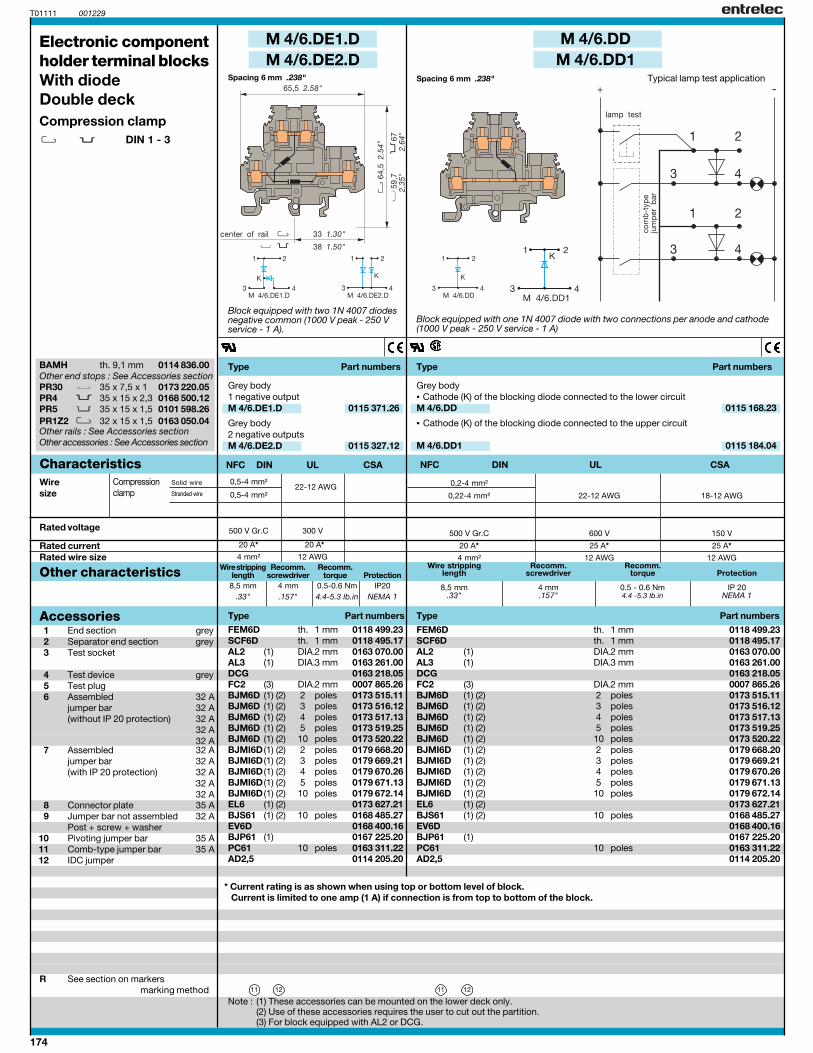
174
NFC DIN UL CSANFC DIN UL CSA
FEM6D 1 mm 0118 499.23SCF6D 1 mm 0118 495.17AL2 (1) 2 mm 0163 070.00AL3 (1) 3 mm 0163 261.00DCG 0163 218.05FC2 (3) 2 mm 0007 865.26BJM6D (1) (2) 2 0173 515.11BJM6D (1) (2) 3 0173 516.12BJM6D (1) (2) 4 0173 517.13BJM6D (1) (2) 5 0173 519.25BJM6D (1) (2) 10 0173 520.22BJMI6D (1) (2) 2 0179 668.20BJMI6D (1) (2) 3 0179 669.21BJMI6D (1) (2) 4 0179 670.26BJMI6D (1) (2) 5 0179 671.13BJMI6D (1) (2) 10 0179 672.14EL6 (1) (2) 0173 627.21BJS61 (1) (2) 10 0168 485.27EV6D 0168 400.16BJP61 (1) 0167 225.20PC61 10 0163 311.22AD2,5 0114 205.20
FEM6D 1 mm 0118 499.23SCF6D 1 mm 0118 495.17AL2 (1) 2 mm 0163 070.00AL3 (1) 3 mm 0163 261.00DCG 0163 218.05FC2 (3) 2 mm 0007 865.26BJM6D (1) (2) 2 0173 515.11BJM6D (1) (2) 3 0173 516.12BJM6D (1) (2) 4 0173 517.13BJM6D (1) (2) 5 0173 519.25BJM6D (1) (2) 10 0173 520.22BJMI6D (1) (2) 2 0179 668.20BJMI6D (1) (2) 3 0179 669.21BJMI6D (1) (2) 4 0179 670.26BJMI6D (1) (2) 5 0179 671.13BJMI6D (1) (2) 10 0179 672.14EL6 (1) (2) 0173 627.21BJS61 (1) (2) 10 0168 485.27EV6D 0168 400.16BJP61 (1) 0167 225.20PC61 10 0163 311.22AD2,5 0114 205.20
0,2-4 mm²
0,22-4 mm² 22-12 AWG 18-12 AWG
500 V Gr.C 600 V 150 V
20 A* 25 A* 25 A*
4 mm² 12 AWG 12 AWG
8,5 mm 4 mm 0.5 - 0.6 Nm IP 20.33" .157" 4.4 -5.3 lb.in NEMA 1
M 4/6.DE1.DM 4/6.DE2.D
M 4/6.DDM 4/6.DD1
11 12 11 12
M 4/6.DD 0115 168.23
M 4/6.DD1 0115 184.04
M 4/6.DE1.D 0115 371.26
M 4/6.DE2.D 0115 327.12
T01111 001229
0,5-4 mm²
0,5-4 mm²
500 V Gr.C 300 V
20 A* 20 A*
4 mm² 12 AWG
8,5 mm 4 mm 0.5-0.6 Nm IP20.33" .157" 4.4-5.3 lb.in NEMA 1
BAMH 0114 836.00
35 x 7,5 x 1PR4 35 x 15 x 2,3 0168 500.12
35 x 15 x 1,5PR1Z2 32 x 15 x 1,5 0163 050.04
* Current rating is as shown when using top or bottom level of block. Current is limited to one amp (1 A) if connection is from top to bottom of the block.
th. 9,1 mmOther end stops : See Accessories sectionPR30 0173 220.05
PR5 0101 598.26
Other rails : See Accessories sectionOther accessories : See Accessories section
Accessories Type Part numbersType Part numbers
Wiresize
Rated voltage
Other characteristics
Rated currentRated wire size
CharacteristicsCompression Solid wire
clamp Stranded wire
Type Part numbers Type Part numbers
Wire stripping Recomm. Recomm.length screwdriver torque Protection
Wire stripping Recomm. Recomm.length screwdriver torque Protection
Block equipped with two 1N 4007 diodesnegative common (1000 V peak - 250 Vservice - 1 A).
Block equipped with one 1N 4007 diode with two connections per anode and cathode(1000 V peak - 250 V service - 1 A)
1 End section grey2 Separator end section grey3 Test socket
4 Test device grey5 Test plug6 Assembled 32 A
jumper bar 32 A(without IP 20 protection) 32 A
32 A32 A
7 Assembled 32 Ajumper bar 32 A(with IP 20 protection) 32 A
32 A32 A
8 Connector plate 35 A9 Jumper bar not assembled 32 A
Post + screw + washer10 Pivoting jumper bar 35 A11 Comb-type jumper bar 35 A12 IDC jumper
Spacing 6 mm .238" Spacing 6 mm .238" Typical lamp test application
Note : (1) These accessories can be mounted on the lower deck only.(2) Use of these accessories requires the user to cut out the partition.(3) For block equipped with AL2 or DCG.
Electronic componentholder terminal blocksWith diodeDouble deckCompression clamp
DIN 1 - 3
R See section on markersmarking method
th.th.DIA.DIA.
DIA.polespolespolespolespolespolespolespolespolespoles
poles
poles
th.th.DIA.DIA.
DIA.polespolespolespolespolespolespolespolespolespoles
poles
poles
Grey body• Cathode (K) of the blocking diode connected to the lower circuit
• Cathode (K) of the blocking diode connected to the upper circuit
Grey body1 negative output
Grey body2 negative outputs
22-12 AWG

175
NOTES

176
NOTES


![M4M Network analyzers Accurate electrical measuring and ......2021/01/13 · IEC 61557-12 IEC 61557-12 PMD/S/K70/0,5 Active energy Class 0,5 acc. to IEC 61557-12 [*] Class 0,5S acc.](https://static.fdocuments.us/doc/165x107/6129b393ad51c45db55eefa1/m4m-network-analyzers-accurate-electrical-measuring-and-20210113-iec.jpg)