FUNDAMENTAL SAFETY OVERVIEW UK-EPR …epr-reactor.co.uk/ssmod/liblocal/docs/V3/Volume 2 - Design...
16
SUB-CHAPTER: E.4 SECTION : E.4.3 PAGE : 1 / 16 UK-EPR FUNDAMENTAL SAFETY OVERVIEW VOLUME 2: DESIGN AND SAFETY CHAPTER E: THE REACTOR COOLANT SYSTEM AND RELATED SYSTEMS 3. REACTOR COOLANT PIPEWORK This section describes the Reactor Coolant Pipework and the Surge Line of the EPR. This pipework is forged austenitic stainless steel 1 . 3.1. DESCRIPTION The pipes of the four primary coolant loops and the surge line are located in the reactor building and form part of the reactor coolant pressure boundary (CPP) [RCPB] belonging to the nuclear steam supply system. The main pipework carries reactor coolant from the reactor vessel to the steam generators and then to the reactor coolant pumps. The fluid is then returned to the reactor vessel. The surge line connects the hot leg of loop 3 to the pressuriser. It is designed to prevent thermal stratification under steady-state operation. There are four reactor coolant loops, each comprising: - a hot leg (BC) [HL] - a crossover leg (BU) [UL] - a cold leg (BF) [CL] Nozzle, branch and piping connections are mounted on each leg for auxiliary and instrumented lines. Hot leg (BC) [HL] (see E.4.3 FIG 1) Each hot leg connects the reactor vessel to a steam generator and comprises of two parts consisting of 3 straight sections and two elbows. Crossover leg (BU) [UL] (see E.4.3 FIG 1) Each crossover leg connects a steam generator to a reactor coolant pump and comprises of three parts consisting of 6 straight sections and 3 elbows. Cold leg (BF) [CL] (see E.4.3 FIG 1) Each cold leg connects a reactor coolant pump (GMPP) [RCP] to the reactor vessel and is produced in a single-piece section that comprises 2 straight sections and 1 elbow. Dimensions The inside diameter of the crossover leg, hot leg and cold legs was primarily sized to minimise pressure drop in the main reactor pipes and to reduce flow velocity. 1 - Elbows are inductive bends or separate elbows - Large nozzles are integral
Transcript of FUNDAMENTAL SAFETY OVERVIEW UK-EPR …epr-reactor.co.uk/ssmod/liblocal/docs/V3/Volume 2 - Design...

SUB-CHAPTER: E.4
SECTION : E.4.3
PAGE : 1 / 16 UK-EPR
FUNDAMENTAL SAFETY OVERVIEW VOLUME 2: DESIGN AND SAFETY
CHAPTER E: THE REACTOR COOLANT SYSTEM AND RELATED SYSTEMS
3. REACTOR COOLANT PIPEWORK
This section describes the Reactor Coolant Pipework and the Surge Line of the EPR. This pipework is forged austenitic stainless steel1.
3.1. DESCRIPTION
The pipes of the four primary coolant loops and the surge line are located in the reactor building and form part of the reactor coolant pressure boundary (CPP) [RCPB] belonging to the nuclear steam supply system.
The main pipework carries reactor coolant from the reactor vessel to the steam generators and then to the reactor coolant pumps. The fluid is then returned to the reactor vessel.
The surge line connects the hot leg of loop 3 to the pressuriser. It is designed to prevent thermal stratification under steady-state operation.
There are four reactor coolant loops, each comprising:
- a hot leg (BC) [HL]
- a crossover leg (BU) [UL]
- a cold leg (BF) [CL]
Nozzle, branch and piping connections are mounted on each leg for auxiliary and instrumented lines.
Hot leg (BC) [HL] (see E.4.3 FIG 1)
Each hot leg connects the reactor vessel to a steam generator and comprises of two parts consisting of 3 straight sections and two elbows.
Crossover leg (BU) [UL] (see E.4.3 FIG 1)
Each crossover leg connects a steam generator to a reactor coolant pump and comprises of three parts consisting of 6 straight sections and 3 elbows.
Cold leg (BF) [CL] (see E.4.3 FIG 1)
Each cold leg connects a reactor coolant pump (GMPP) [RCP] to the reactor vessel and is produced in a single-piece section that comprises 2 straight sections and 1 elbow.
Dimensions
The inside diameter of the crossover leg, hot leg and cold legs was primarily sized to minimise pressure drop in the main reactor pipes and to reduce flow velocity.
1 - Elbows are inductive bends or separate elbows - Large nozzles are integral

SUB-CHAPTER: E.4
SECTION : E.4.3
PAGE : 2 / 16 UK-EPR
FUNDAMENTAL SAFETY OVERVIEW VOLUME 2: DESIGN AND SAFETY
CHAPTER E: THE REACTOR COOLANT SYSTEM AND RELATED SYSTEMS
Surge line pipe (see E.4.3 FIG 2)
The surge line comprises seven austenitic steel segments entirely forged and weldless.
3.2. SUB-ASSEMBLIES DESIGN (NOZZLES AND SLEEVES)
General design
There is a design requirement that the hot leg (BC) [HL] is forged with a separate forged elbow.
The cold leg (BF) [CL] is forged entirely in a single piece with a vessel inlet elbow machined from the forging.
The crossover leg (BU) [UL] is in three sections to enable, primarily, ease of assembly.
Welds between dissimilar metals are carried out in the shop and are needed at junctions with low alloy steel components (see section E.3.7).
Each weld between dissimilar metals is combined with an intermediary weld to produce a safe end allowing welds between similar metals to be carried out on site.
The welding between a connecting line and the main reactor coolant system pipework involves similar metals.
Nozzle design
Large nozzles (NB > 150mm)
These nozzles are forged integrally with the main reactor coolant pipework. They are machined after forging.
Two or three large nozzles are machined out of the same collar per loop.
Small Nozzles (NB < 150mm)
In recognition of the experience feedback regarding the mixing zone, small nozzles and bosses are attached by welding. The exception is for the main chemical and volume control system (RCV) [CVCS] charging-line nozzle which is integral with the main reactor coolant pipework (forged as a single piece).
Thermal sleeves
If the fatigue analysis of a nozzle leads to a cumulative usage factor exceeding the RCC-M (EPR version, see sub-chapter B.6 subsection B3000 criteria), then it is protected by the installation of a thermal sleeve. The sleeve is machined from an intermediate forged part welded to the nozzle in the shop. Based on past experience, it is expected that only the RCV [CVCS] nozzles may require a sleeve. The fatigue analysis will be performed later in the Detailed Design Phase.

SUB-CHAPTER: E.4
SECTION : E.4.3
PAGE : 3 / 16 UK-EPR
FUNDAMENTAL SAFETY OVERVIEW VOLUME 2: DESIGN AND SAFETY
CHAPTER E: THE REACTOR COOLANT SYSTEM AND RELATED SYSTEMS
3.3. DESIGN CALCULATIONS
A sizing calculation is performed on the primary piping, the surge line, the integral nozzles and the welded nozzles in accordance with the RCC-M (EPR version) Code (see sub-chapter B.6, paragraph B3000).
The reinforcement is not on the pipe but on the nozzle side.
The thicknesses of the straight sections and the thicknesses of the outside bend regions on the curved sections are determined in accordance with B3600 in the RCC-M (EPR version). The thickness of the outside bend regions of curved portions are increased to ensure a suitable stress level.
Furthermore, 90° or oblique branch connections integral with the piping are checked by calculation according to the rules for the reinforcement of openings of B3600 in the RCC-M (EPR version).
Break preclusion
The technology for the reactor coolant pipework complies with the requirements of the break preclusion concept as defined in sub-chapter E.2.
3.4. METHODS AND TOOLS FOR STRESS ANALYSIS
The reactor coolant primary pipework is analysed with loads corresponding to normal, upset, emergency and faulted conditions. The stress analysis performed depends on the operational mode under consideration.
3.4.1. Load conditions
The loads used for the stress analysis are listed in section C.6.1.
3.4.2. Loads used for stress analysis
The loads used for stress analysis depend on the operating conditions under consideration and then on the criteria level.
In accordance with the RCC-M requirements (see Chapter B.6), loads are classified into 4 categories:
- design conditions (1st category)
- normal operation and upset conditions(2nd category)
- emergency conditions (3rd category)
- fault conditions (4th category)

SUB-CHAPTER: E.4
SECTION : E.4.3
PAGE : 4 / 16 UK-EPR
FUNDAMENTAL SAFETY OVERVIEW VOLUME 2: DESIGN AND SAFETY
CHAPTER E: THE REACTOR COOLANT SYSTEM AND RELATED SYSTEMS
3.4.3. Stress analysis tools
Calculations are carried out in accordance with sections B3600 and B3200 of the RCC-M code (see sub-Chapter B.6).
The requirements of the code concern the range of primary plus secondary stresses. Determination of the total stresses requires the calculation of temperature transients through the thickness of the component wall.
The transients as defined in section C.6.1 are used to compute these fluctuations. ROCOCO, a one-dimensional finite difference heat transfer program is used to solve the thermal transient calculation.
The outer surface of the pipework is assumed to be adiabatic while the inner surface boundary experiences the temperature of the coolant fluid. Fluctuations in the temperature of the coolant fluid produce a temperature distribution through the pipe wall thickness which varies with time. This temperature distribution is sub-divided into four parts; following RCC-M (EPR version) requirements:
- Average temperature (TA) is the average through-wall temperature of the pipe which contributes to general expansion loads.
- Radial linear thermal gradient which contributes to through-wall bending moment (∆T1).
- Radial non-linear thermal gradient (∆T2) which contributes to peak stress associated with shearing of the surface.
- Discontinuity temperature (TA - TB) representing the difference in average temperature at cross sections on each side of a discontinuity
Each transient is described by at least two load sets representing the maximum and minimum stress state during each transient. The construction of the load sets is accomplished by combining the following to yield the maximum (minimum) stress state during each transient.
- ∆T1
- ∆T2
- αATA - αBTB
- Moment loads due to TA
- Pressure loads
The ranges of primary plus secondary stresses and the total stress ranges are then computed following the equations of RCC-M (EPR version) section B3653. These stress ranges may also be computed using finite element analysis.
For all relevant load set combinations, the primary-plus-secondary and peak stress intensities, elasto-plastic stress correction factors (Ke) and cumulative usage factors (CUF), are calculated in accordance with RCC-M (EPR version) section B3650.

SUB-CHAPTER: E.4
SECTION : E.4.3
PAGE : 5 / 16 UK-EPR
FUNDAMENTAL SAFETY OVERVIEW VOLUME 2: DESIGN AND SAFETY
CHAPTER E: THE REACTOR COOLANT SYSTEM AND RELATED SYSTEMS
The incremental usage factor is calculated for the combination of load sets yielding the highest alternating stress intensity range. The next most severe combination is then determined and the incremental usage factor calculated. This procedure is repeated until all fatigue relevant load combinations have been covered. The total cumulative usage factor at a point is the summation of the incremental usage factors.
3.5. STRESS CALCULATIONS
A simplified stress analysis of the coolant loop has been performed for pipes, elbows and nozzles.
3.5.1. Primary stresses
Calculations, in accordance with the equation (9) of the RCC-M (EPR version) section B3600, show that, with the Basic Design loadings, the criteria defined in the RCC-M (EPR version) for primary stresses are fulfilled in each area of the coolant loop.
3.5.2. Fatigue analysis
Calculations, in accordance with the equation (12) of the RCC-M (EPR version, See sub-chapter B.6, section B3600), show, that with Basic Design loadings (Thermal expansion moments), the criteria defined in the RCC-M (EPR version) for secondary stresses are fulfilled in each area of the coolant loop.
For fatigue analysis, a comparison is made with French N4 plants.
After comparison of the geometry, the thermal loads and number of cycles, it is possible to conclude that all circumferential welds in the reactor coolant system demonstrate a usage factor less than 0.1. Some specific zones may have a higher usage factor value while remaining acceptable from the fatigue damage viewpoint (mixing zones).
If it appears necessary to reduce the usage factor of the nozzles of the connected lines during the Detailed Design analysis of the final list of transients , thermal sleeves will be used.
The RCV [CVCS] nozzle is a special case. The EPR transients are based on a “letdown control method” that cannot be extrapolated from an N4 plant using a “letdown control method”. The definition of the transients affecting the RCV [CVCS] nozzle will be supplied by comparison with the Neckarwestheim plant which uses the “letdown control method”.
3.6. MATERIAL SELECTION
3.6.1. Base materials
The selection of base materials is the result of significant feedback and manufacturing improvements, taking the following requirements into account, in accordance with the technical rules drawn up for the fabrication of the future reactor coolant system:
- excellent mechanical properties with a significant margin (according to the design requirements)
- adequate toughness

SUB-CHAPTER: E.4
SECTION : E.4.3
PAGE : 6 / 16 UK-EPR
FUNDAMENTAL SAFETY OVERVIEW VOLUME 2: DESIGN AND SAFETY
CHAPTER E: THE REACTOR COOLANT SYSTEM AND RELATED SYSTEMS
- corrosion resistance
- easy manufacturing and good weldability
- manufacturing and in-service inspections
- significant reduction in the number of welds
- easy replacement after long operating periods (if necessary before the end of the 60-year lifespan)
All these requirements are satisfied when forged legs are used, with forged nozzles and elbows, in low-carbon content austenitic stainless steels.
These materials present the following benefits:
- uniformity of material for all piping (including connected lines)
- high toughness in all situations (even in the event of cold water injection)
- ease of on-site welding, no heat treatment needed
- ease of on-site connection of numerous auxiliary pipelines and the surge line
- improved manufacturing and associated non-destructive tests
- ability to undergo specified in-service inspection
Grade:
The materials grades used to construct the main reactor coolant pipework and surge line are selected in such as way as to minimise erosion-corrosion and ensure compatibility with the environment in which they are used.
The specified materials are austenitic stainless steel.
For the main reactor coolant system pipework, a single grade with controlled nitrogen content is selected.
For the surge line, another grade with controlled nitrogen content could be utilised.
The grade of welded nozzles is the same as that for the surge line.
These grades have very low carbon content and therefore require no stabilisation. Parts produced are obtained by forging, with a forging ratio of greater than 3, which provides fine grains (at least ASTM 1) and adequately consistent mechanical properties. The parts are delivered already heat-treated in order to remove any risk of intergranular corrosion in service.
The parts, as delivered, can be welded with no risk of sensitisation to intergranular corrosion and with no loss of mechanical properties even in the heat-affected zone.

SUB-CHAPTER: E.4
SECTION : E.4.3
PAGE : 7 / 16 UK-EPR
FUNDAMENTAL SAFETY OVERVIEW VOLUME 2: DESIGN AND SAFETY
CHAPTER E: THE REACTOR COOLANT SYSTEM AND RELATED SYSTEMS
3.6.2. Filler metal
A narrow gap orbital TIG (TOCE) [NGOT] automatic welding procedure with an ER 316 L wire is used for circumferential welds on reactor coolant system pipework. Manual TIG (TCE) [NGT] welding with E 316 L coated electrodes is used for welded nozzles.
The filler metals used for manufacturing and welding on-site are assessed to meet requirements relating to welding procedures.
3.6.3. Mechanical properties
The values specified for base forged materials in the main reactor coolant system pipework and surge line are given in the RCC-M (STR M 3305 and M 3313) (see sub-chapter B.6) with the possible addition of further requirements detailed in the equipment specifications.
The filler metals used for manufacturing and welding on-site are assessed to meet requirements relating to welding procedures. The assessment establishes whether they have the same properties as the base materials.
3.7. MANUFACTURING PROCESS FOR THE MAIN COOLANT LINES AND SURGE LINE
Procurement
According to the loop design and to the manufacturing technology applicable, the individual forged parts to be supplied are as follows:
- the hot leg comprising two weldless forged sections. One comprises the integral large nozzles and an elbow and the other consists of a forged elbow connecting to the steam generator.
- the cold leg comprising a single single-piece forged section which is a straight section with large integral nozzles (∅ ≥ 150 mm) and RCV [CVCS]) and a separate forged elbow
- a crossover leg made comprising three sections each consisting of a straight section and an elbow
- a surge line, using inductive bends when required, made of 7 straight parts .
The forging operations are optimised to obtain the required mechanical properties and to satisfy a good ultrasonic permeability in order to assure in service inspectability.
Previous French experience and the qualification results of the manufacture of these components shows that the properties will be achieved if the forging ratio is not less than 3 and the grain size not less than ASTM 1.
Hot and cold legs
The seamless sections are produced by forging a solid ingot of 115t and 161.6t respectively. Heating is carried out several times to permit the successive blooming, drawing, nozzle-forging and final shaping operations.

SUB-CHAPTER: E.4
SECTION : E.4.3
PAGE : 8 / 16 UK-EPR
FUNDAMENTAL SAFETY OVERVIEW VOLUME 2: DESIGN AND SAFETY
CHAPTER E: THE REACTOR COOLANT SYSTEM AND RELATED SYSTEMS
A significant amount of machining is needed to bore the inside of the pipes and produce the required shape for the nozzles.
Final machining is carried out before acceptance testing and related non-destructive tests, which are as follows:
- liquid-penetrant testing of machined surfaces, finished inside and out
- ultrasonic inspection by longitudinal and transverse beam on the entire volume
Crossover leg
The cross over leg is obtained from a hollow ingot of 75 t, for which the forging sequences are significantly reduced because of the simple design (no nozzles). Only a few heating cycles are necessary to perform the sequences of hot drawing. Three parts are obtained by sawing the rough product.
Each section must be machined before induction bending of the three elbows.
After the final solution heat treatment, the exact geometry shall be achieved either by machining or grinding before performing the acceptance tests and associated non destructive examinations. The same examinations are used for the cold and hot legs.
Workshop manufacturing
Shop manufacturing is reduced to small nozzles and fitting welding between two seamless parts.
Nevertheless, welding of hydrotest blanks is necessary to perform tests at the required pressure according to RCC-M EPR version (see sub-Chapter B.6), B5000.
After cutting of blanks by mechanical means, final cleaning shall be performed before packaging and shipment to the plant for field erection.
Field erection
Assembly of primary loop pipework requires only a small number of welds between similar metal. Such welds need no preheating or post-weld heat treatment and are carried out by fully automated narrow gap orbital TIG (TOCE) [NGOT] welding. For one reactor coolant system loop there are (see E.4.3. FIG 3) nine welds between similar metals, including eight on-site, because the crossover leg is delivered in three sections. The intermediate welds of the BC [HL] are carried out in shop (2+1 welds on the BC [HL]and the BF [CL] and 4 on the BU [UL]).
Subsequent inspections of the welds are:
- liquid-penetrant testing
- radiographic inspection
- ultrasonic testing
For the surge line, a special procedure is necessary because of the need for a hydrotest of the line after connection by welding of the 7 segments. Six welds are performed to complete the full surge line and the blanks are welded at each end for the hydrotest. After a successful hydrotest, the blanks are removed and the line connected by narrow gap orbital TIG (TOCE) [NGOT] welding to the pressuriser at one end and to the hot leg (on a nozzle) at the other end.

SUB-CHAPTER: E.4
SECTION : E.4.3
PAGE : 9 / 16 UK-EPR
FUNDAMENTAL SAFETY OVERVIEW VOLUME 2: DESIGN AND SAFETY
CHAPTER E: THE REACTOR COOLANT SYSTEM AND RELATED SYSTEMS
All welds on the main reactor coolant lines and surge line that are accessible must be dressed flush inside and outside the pipes.
In the mixing zones with significant temperature variations, the inner surface treatment of (RCV [CVCS] nozzles – surge line nozzle / (BC) [HL] – nozzles at 45°), must achieve roughness values lower than the usual practice to minimise any risk of local thermo-hydraulic phenomena.
3.8. INSPECTABILITY
Inspectability is the capacity of the design to allow checks or inspections (installation and materials).
3.8.1. Inspections during manufacturing
Materials used for the main reactor coolant lines must intrinsically be able to be inspected during manufacturing.
Volumetric checks, radiographic or ultrasonic inspections must be carried out on the base material as well as on deposited metal (welds).
The austenitic stainless steel base material in the main reactor coolant pipework and surge line must be subject to a volumetric inspection. The sensitivity of the inspection has been proved on test specimens.
The choice of inspection method (radiography or ultrasonics) depends on the shape and location of the most likely defect to arise for a given manufacturing method.
Consequently, ultrasonic inspection is most frequently used for the forged products procured and radiographic inspection is preferred for welds. As a result, inspection requirements can be summarised as follows:
- Primary coolant system pipework loops:
- surface inspection = 100% liquid-penetrant testing of inner and outer surfaces
- volumetric inspection = 100% by ultrasound from the outer surface (inspection from the inner surface may also be carried out for some zones, in particular for single-piece nozzles).
- Surge line:
- surface inspection = 100% liquid-penetrant testing of outer surfaces
- volumetric inspection = 100% by ultrasound from the outer surface.
- Connection welds:
- surface inspection = 100% liquid-penetrant testing of inner (where accessible) and outer surfaces.
Note: Liquid-penetrant testing must be carried out after the welds have been ground flush.

SUB-CHAPTER: E.4
SECTION : E.4.3
PAGE : 10 / 16 UK-EPR
FUNDAMENTAL SAFETY OVERVIEW VOLUME 2: DESIGN AND SAFETY
CHAPTER E: THE REACTOR COOLANT SYSTEM AND RELATED SYSTEMS
- volume inspection = 100% radiographic inspection of the weld and an area of 10 mm each side of the weld.
3.8.2. In-service inspections
The typical areas for in-service inspections are:
- welds
- base material areas with a high usage factor (> 0.5).
All welds whose location is indicated in figures E.4.3 FIG 3 & 4 can be inspected in service, in particular by ultrasonic testing (see E.4.3 TAB 1 and 2).
The procurement requirements applying to base materials (reduction ratio and grain size) associated with the welding process used for the main welds (narrow gap orbital TIG (TOCE) [NGOT] welding) ensures that, if needed, the resulting ultrasonic permeability achieves the necessary sensitivity for in-service ultrasonic inspection.

SUB-CHAPTER: E.4
SECTION : E.4.3TABLE : 1 PAGE : 11/ 16
UK-EPR
FUNDAMENTAL SAFETY OVERVIEW VOLUME 2: DESIGN AND SAFETY
CHAPTER E: THE REACTOR COOLANT SYSTEM AND RELATED SYSTEMS
E.4.3 TAB 1: INPSECTABILITY OF THE PRIMARY LOOP
DESCRIPTION ITEM INSPECTION
Vessel end / BC [HL] H1 RT-UT-LP-V
Elbow H2 RT-UT-LP-V
BC [HL] / GV [SG] end H3 RT-UT-LP-V
GV [SG] end / BU [UL] section A U1 RT-UT-LP-V
BU [UL] section A / BU [UL] section B2 (1) U2 UT-LP-V
BU [UL] section B / BU [UL] section C (1) U3 UT-LP-V
BU [UL] section C / pump end (1) U4 UT-LP-V
pump end / BF [CL] (1) C1 UT-LP-V
BF [CL] / Vessel end C2 RT-UT-LP-V
Nozzle welds - UT partial-LP-V
Nozzles/ auxiliary line - UT-LP-V
Abbreviations: UT (ultrasound inspection)
RT (radiographic inspection)
LP (liquid-penetrant testing)
V (visual)
1: Radiographic inspection not used owing to access difficulties, other than for U4 and C1
welds if the reactor coolant pump hydraulics are removed.

SUB-CHAPTER: E.4
SECTION : E.4.3TABLE : 2 PAGE : 12 / 16
UK-EPR
FUNDAMENTAL SAFETY OVERVIEW VOLUME 2: DESIGN AND SAFETY
CHAPTER E: THE REACTOR COOLANT SYSTEM AND RELATED SYSTEMS
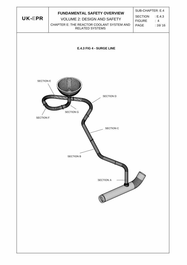
E.4.3 TAB 2: INSPECTABILITY OF THE SURGE LINE
DESCRIPTION INSPECTIONS (2)
(BC) [HL] / nozzle Section A UT-LP-V
Section A / Section B UT-LP-V
Section B / Section C UT-LP-V
Section C / Section D UT-LP-V
Section D / Section E UT-LP-V
Section E / Section F UT-LP-V
Section F / Section G UT-LP-V
Section G / pressuriser end UT-LP-V
Abbreviations: UT (ultrasound inspection)
RT (radiographic inspection)
LP (liquid-penetrant testing)
V (visual)
2 Radiographic inspection not used owing to access issues

SUB-CHAPTER: E.4
SECTION : E.4.3FIGURE : 1 PAGE : 13/ 16
UK-EPR
FUNDAMENTAL SAFETY OVERVIEW VOLUME 2: DESIGN AND SAFETY
CHAPTER E: THE REACTOR COOLANT SYSTEM AND RELATED SYSTEMS
E.4.3 FIG 1 – PRIMARY LOOP
H3

SUB-CHAPTER: E.4
SECTION : E.4.3FIGURE : 2 PAGE : 14/ 16
UK-EPR
FUNDAMENTAL SAFETY OVERVIEW VOLUME 2: DESIGN AND SAFETY
CHAPTER E: THE REACTOR COOLANT SYSTEM AND RELATED SYSTEMS
E.4.3 FIG 2 - SURGE LINE

SUB-CHAPTER: E.4
SECTION : E.4.3FIGURE : 3 PAGE : 15/ 16
UK-EPR
FUNDAMENTAL SAFETY OVERVIEW VOLUME 2: DESIGN AND SAFETY
CHAPTER E: THE REACTOR COOLANT SYSTEM AND RELATED SYSTEMS
E.4.3 FIG 3 – REACTOR COOLANT SYSTEM
SUB-CHAPTER: E.4
SECTION : E.4.3FIGURE : 4 PAGE : 16/ 16
UK-EPR
FUNDAMENTAL SAFETY OVERVIEW VOLUME 2: DESIGN AND SAFETY
CHAPTER E: THE REACTOR COOLANT SYSTEM AND RELATED SYSTEMS
E.4.3 FIG 4 - SURGE LINE
SECTION A
SECTION B
SECTION C
SECTION D
SECTION G
SECTION F
SECTION E