PCSR – Sub-chapter 3.4 – Mechanical systems and...
236
Title: PCSR – Sub-chapter 3.4 – Mechanical systems and components UKEPR-0002-036 Issue 05 Total number of pages: 236 Page No.: I / VI Chapter Pilot: F. GHESTEMME Name/Initials Date 31-10-2012 Approved for EDF by: A. MARECHAL Approved for AREVA by: G. CRAIG Name/Initials Date 31-10-2012 Name/Initials Date 31-10-2012 REVISION HISTORY Issue Description Date 00 First issue for INSA information 14-01-2008 01 Integration of technical and co-applicant review comments 29-04-2008 02 June 2009 update including: - Text clarification - Insertion of references - Technical update to account for December 2009 design freeze including new PSRVs design (sections 1.1 and 1.5), addition of tests results (section 2), modification of rod speed and classification of position indicator coils (section 4) and update of LMP column design and number of temperature sensors (section 5). 29-06-2009 03 Consolidated PCSR update - Minor editorial changes - Update and addition of references - Introduction of High Integrity Component (HIC) safety case (§0.3, §0.4) - Introduction of monophasic start-up mode (§1.1.2.1) - Addition of a new section (§1.1.8) covering Pressurised Thermal Shock - Addition of a new section (§1.6) addressing fast fracture risk for HIC - Introduction of 20MND5 steel grade for steam generator and pressuriser (§3) 31-03-2011 Continued on next page Text within this document that is enclosed within curly brackets “{…}” is AREVA or EDF Commercially Confidential Information and has been removed.
-
Upload
nguyentruc -
Category
Documents
-
view
217 -
download
1
Transcript of PCSR – Sub-chapter 3.4 – Mechanical systems and...

Title: PCSR – Sub-chapter 3.4 – Mechanical systems and
components
UKEPR-0002-036 Issue 05
Total number of pages: 236 Page No.: I / VI
Chapter Pilot: F. GHESTEMME
Name/Initials
Date 31-10-2012
Approved for EDF by: A. MARECHAL Approved for AREVA by: G. CRAIG
Name/Initials Date 31-10-2012 Name/Initials
Date 31-10-2012
REVISION HISTORY
Issue Description Date
00 First issue for INSA information 14-01-2008
01 Integration of technical and co-applicant review comments 29-04-2008
02 June 2009 update including:
- Text clarification
- Insertion of references
- Technical update to account for December 2009 design freeze including new PSRVs design (sections 1.1 and 1.5), addition of tests results (section 2), modification of rod speed and classification of position indicator coils (section 4) and update of LMP column design and number of temperature sensors (section 5).
29-06-2009
03 Consolidated PCSR update - Minor editorial changes - Update and addition of references - Introduction of High Integrity Component (HIC) safety case (§0.3, §0.4) - Introduction of monophasic start-up mode (§1.1.2.1) - Addition of a new section (§1.1.8) covering Pressurised Thermal Shock - Addition of a new section (§1.6) addressing fast fracture risk for HIC - Introduction of 20MND5 steel grade for steam generator and
pressuriser (§3)
31-03-2011
Continued on next page
Text within this document that is enclosed within curly brackets “{…}” is AREVA or EDF Commercially Confidential Information and has been removed.

Title: PCSR – Sub-chapter 3.4 – Mechanical systems and
components
UKEPR-0002-036 Issue 05 Page No.:
II / VI
REVISION HISTORY (Cont’d)
Issue Description Date
04 Consolidated PCSR update: - References listed under each numbered section or sub-section heading
numbered [Ref-1], [Ref-2], [Ref-3], etc - Minor editorial changes - Update of references (§0.3.6, §1.6.1, §1.2, §1.3.2.1, §5, §6) - Clarification of text (§4.3.1, §4.3.2) - Update to clarify the HIC status of the MSIV (§0.3.6) - Update of Section 3.4.1.2 – Tables 1 & 2, to remove reference to ETC-S
and update in line with new reference - Correction of category 3 OPP criterion (§1.5.2.1) - Update in line with FMA and NDT presented in PCSR Chapters 5 and 10
to clarify the status of base metal in the avoidance of fracture demonstration (§1.6)
- Addition of new paragraphs to clarify the status of non-qualified inspections in the avoidance of fracture demonstration (§1.6.3)
- Inclusion of value of 6 million steps, as the CRDM design life, with testing performed up to 9 million steps (§4.8)
30-08-2012
05 Consolidated PCSR update: - Modifications to clarify application of “break preclusion” and HIC (§0.3.6,
§1.2, §1.4)
- Update to reflect the changes to integrity claims on the non-isolable parts of the fuel pool pipework (§0.3.6)
31-10-2012

Title: PCSR – Sub-chapter 3.4 – Mechanical systems and
components
UKEPR-0002-036 Issue 05 Page No.:
III / VI
Copyright © 2012
AREVA NP & EDF All Rights Reserved
This document has been prepared by or on behalf of AREVA NP and EDF SA in connection with their request for generic design assessment of the EPRTM design by the UK nuclear regulatory authorities. This document is the property of AREVA NP and EDF SA. Although due care has been taken in compiling the content of this document, neither AREVA NP, EDF SA nor any of their respective affiliates accept any reliability in respect to any errors, omissions or inaccuracies contained or referred to in it. All intellectual property rights in the content of this document are owned by AREVA NP, EDF SA, their respective affiliates and their respective licensors. You are permitted to download and print content from this document solely for your own internal purposes and/or personal use. The document content must not be copied or reproduced, used or otherwise dealt with for any other reason. You are not entitled to modify or redistribute the content of this document without the express written permission of AREVA NP and EDF SA. This document and any copies that have been made of it must be returned to AREVA NP or EDF SA on their request. Trade marks, logos and brand names used in this document are owned by AREVA NP, EDF SA, their respective affiliates or other licensors. No rights are granted to use any of them without the prior written permission of the owner.
Trade Mark EPRTM is an AREVA Trade Mark.
For information address:
AREVA NP SAS
Tour AREVA 92084 Paris La Défense Cedex
France
EDF Division Ingénierie Nucléaire
Centre National d'Equipement Nucléaire 165-173, avenue Pierre Brossolette
BP900 92542 Montrouge
France
Title: PCSR – Sub-chapter 3.4 – Mechanical systems and
components
UKEPR-0002-036 Issue 05 Page No.:
IV / VI
TABLE OF CONTENTS
0. SAFETY REQUIREMENTS
0.1. SAFETY FUNCTIONS
0.2. FUNCTIONAL CRITERIA
0.3. REQUIREMENTS RELATING TO THE DESIGN
1. TOPICS SPECIFIC TO THE MECHANICAL COMPONENTS
1.1. DESIGN TRANSIENTS
1.2. LOADING SPECIFICATION
1.3 MECHANICAL ANALYSIS OF THE CPP [RCPB]
1.4. HYDRAULIC LOADING IN THE CSP [SSPB] AFTER MAIN STEAM LINE BREAK (MSLB) AND FEEDWATER LINE BREAK (FWLB)
1.5 OVERPRESSURE PROTECTION ANALYSES
1.6 FAST FRACTURE RISK
2. TESTS AND DYNAMIC ANALYSES
2.1. ANALYSIS OF VIBRATION EFFECTS
2.2. SEISMIC QUALIFICATION
2.3. DYNAMIC RESPONSE OF REACTOR VESSEL INTERNALS UNDER OPERATIONAL FLOW EXCITATION
2.4. PRE-OPERATIONAL FLOW-INDUCED VIBRATION TESTING OF REACTOR VESSEL INTERNALS
2.5. DYNAMIC SYSTEM ANALYSIS OF THE RPV INTERNALS UNDER FAULTED CONDITIONS
2.6. CORRELATION OF RPV INTERNALS VIBRATION TESTS WITH ANALYTICAL RESULTS
3. REFERENCE SYSTEM FOR THE DESIGN OF M1, M2 OR M3 SAFETY CLASSIFIED MECHANICAL EQUIPMENT
3.1. VERSION OF THE RCC-M USED

Title: PCSR – Sub-chapter 3.4 – Mechanical systems and
components
UKEPR-0002-036 Issue 05 Page No.:
V / VI
3.2. LOAD COMBINATIONS, TRANSIENTS AND STRESS LIMITS
3.3. OPERABILITY UNDER SEISM OF M2 OR M3 SAFETY CLASSIFIED PUMPS AND VALVES
3.4. COMPONENT SUPPORTS
4. CONTROL ROD DRIVE MECHANISM
4.0. SAFETY REQUIREMENTS
4.1. GENERAL
4.2. DESCRIPTION
4.3. DESIGN BASIS
4.4. MATERIALS
4.5. PRELIMINARY TESTS
4.6. EXPERIENCE IN OPERATION
4.7. IN-SERVICE INSPECTABILITY AND REPLACEABILITY
4.8. LIFE EXPECTANCY
4.9. INTERFACES WITH THE CONTROL ROD DRIVE MECHANISM
5. REACTOR PRESSURE VESSEL – UPPER CORE SUPPORT STRUCTURES
5.0. SAFETY REQUIREMENTS
5.1. GENERAL INFORMATION
5.2. DESCRIPTION
5.3. MECHANICAL DESIGN
5.4. HYDRAULIC DESIGN
5.5. SIZING CALCULATIONS
5.6. ARRANGEMENT
5.7. INSPECTABILITY AND REPAIRABILITY
5.8. OPERATING EXPERIENCE

Title: PCSR – Sub-chapter 3.4 – Mechanical systems and
components
UKEPR-0002-036 Issue 05 Page No.:
VI / VI
5.9. CORE INSTRUMENTATION
6. REACTOR PRESSURE VESSEL – LOWER INTERNALS
6.0. SAFETY REQUIREMENTS
6.1. DESIGN PRINCIPLES
6.2. OPERATING CONDITIONS
6.3. HYDRAULIC DESIGN
6.4. MECHANICAL DESIGN
6.5. OPERATING EXPERIENCE
6.6. MATERIALS
6.7. MANUFACTURE AND SUPPLY
7. IN-SERVICE TESTING OF PUMPS AND VALVES
7.1. DEFINITION AND OBJECTIVES
7.2. METHODOLOGY
7.3. CLASSIFICATION OF FUNCTIONS

PRE-CONSTRUCTION SAFETY REPORT
CHAPTER 3: GENERAL DESIGN AND SAFETY ASPECTS
SUB-CHAPTER : 3.4
PAGE : 1 / 230
Document ID.No. UKEPR-0002-036 Issue 05
SUB-CHAPTER 3.4 - MECHANICAL SYSTEMS AND COMPONENTS
0. SAFETY REQUIREMENTS
0.1. SAFETY FUNCTIONS
The design of the mechanical systems and components is based on appropriate studies and tests that ensure the equipment can perform its function during its expected lifetime. The three main safety functions consist of:
• control of fuel reactivity.
• fuel heat removal,
• containment of radioactive material.
0.2. FUNCTIONAL CRITERIA
The mechanical components are divided into two categories, depending on whether the device is considered to have an active or passive role in bringing the reactor to, and maintaining it in a safe shutdown state.
Active components
Active components are usually actuated either manually or automatically through the use of an electric motor or by a hydraulic or pneumatic system. They are actuated or controlled through the use of a remote control system. Other automatic components that operate without external power supply and or remote control (e.g. safety valves) are considered as active components if they contain mechanical parts that move in the accomplishment of their safety function.
Passive components
A passive component needs no actuation or energy supply to fulfil its safety function. Tanks, heat exchangers or valves that do not need to change position for safety purpose are passive components.
Depending on the component type (active or passive) and its intended safety function, the following requirements must be addressed in the design:
• Operability: the ability of an active component (including all the necessary auxiliary, supporting and energy-supply systems) to fulfil its safety functions and thus meet the safety objectives.
• Functional capability: ability of all pressure-bearing parts of components (active or passive) to withstand the specified loads so that deformations occurring in these components are limited such that its operational capacity is not impaired by a possible flow reduction.

PRE-CONSTRUCTION SAFETY REPORT
CHAPTER 3: GENERAL DESIGN AND SAFETY ASPECTS
SUB-CHAPTER : 3.4
PAGE : 2 / 230
Document ID.No. UKEPR-0002-036 Issue 05
• Integrity: the ability of all parts of active and passive components subject to pressure to withstand the specified loadings and ensure fluid containment,.
• Stability: the ability of an active or passive component to withstand loads that tend to change its orientation or position (for instance, causing it to sway, fall or slide unacceptably, or causing parts to shear). A component’s stability includes, among other things, the necessary resistance and stability of its supports.
0.3. REQUIREMENTS RELATING TO THE DESIGN
0.3.1. Applicable regulations
Requirements specific to the design and construction of mechanical equipment are given in sections B.1.2, B 1.3, B.2.3.6 and B.2.3.7 of the Technical Guidelines (see Sub-chapter 3.1).
0.3.2. Safety classification
Mechanical components that fulfil a safety function are safety classified. They are divided into safety classes according to the requirements defined in Chapter 3.2. These safety classes lead to quality levels for design and manufacturing of mechanical components.
0.3.3. Design requirements for mechanical equipment
This section applies to the following equipment:
• Mechanical components subject to pressure: pipework, tanks, vessels, pumps, valves and watertight mechanical containment penetrations.
• Non-pressure retaining components: supports for mechanical components, Reactor Pressure Vessel internals, some mechanical components in the ventilation systems, handling equipment.
The design of a mechanical plant item must enable it to fulfil the safety functions for which it is designed.
In order to define the loads applied to these components, all the loading conditions requiring the equipment to fulfil its safety function must be identified. The component robustness is proved through criteria specific to the probability of occurrence of these loading conditions (see section 1 of this sub-chapter).
A loading condition experienced by a component is characterised by a set of loads that determines the stresses to which the component can be subjected: pressure, temperature, internal and external forces, etc.
These loading conditions result either from internal events (PCC and RRC situations, see Chapters 14 and 16), internal hazards (see Sub-chapter 3.1 and Sub-chapter 13.2) or external hazards (see Sub-chapter 3.1 and Sub-chapter 13.1). Section 1 of this sub-chapter describes loads and combination rules.
The loading conditions (and the loads associated with them) are defined to envelope all operating conditions for which the mechanical equipment is required.

PRE-CONSTRUCTION SAFETY REPORT
CHAPTER 3: GENERAL DESIGN AND SAFETY ASPECTS
SUB-CHAPTER : 3.4
PAGE : 3 / 230
Document ID.No. UKEPR-0002-036 Issue 05
0.3.4. Overpressure protection
Overpressure protection is ensured by system safety features related notably to relief and safety valves, or reactor trip which come in addition to normal pressure and temperature control.
The safety requirements for protection against overpressure are given in sections B 2.3.6 and B 2.3.7 of the Technical Guidelines.
Protection against overpressure applies to the design of all pressurised mechanical systems and in particular to the design of the reactor coolant pressure boundary (CPP [RCPB]) and the secondary system pressure boundary (CSP [SSPB]).
0.3.5. Qualification
The mechanical components necessary for the operation of the systems fulfilling a safety function must be qualified. The qualification process must be appropriately specified for each type of component.
Qualification principles and requirements are presented in a dedicated section (see Sub-chapter 3.6).
0.3.6. High Integrity Components
The mechanical components can be classified in three categories depending on the way their failure is considered in the safety analysis [Ref-1] [Ref-2]:
1. Components whose failure is explicitly considered within the deterministic safety analysis with a very conservative approach and assumptions. Failure of these components is taken into account with regards to the internal hazards methodology; when these failures have direct consequences on the core safety, the detailed consequences on the plant process are analysed through the fault analyses. The different families of these components are presented in the following table:

PRE-CONSTRUCTION SAFETY REPORT
CHAPTER 3: GENERAL DESIGN AND SAFETY ASPECTS
SUB-CHAPTER : 3.4
PAGE : 4 / 230
Document ID.No. UKEPR-0002-036 Issue 05
Component Failure assumptions considered as initiating events for deterministic
analyses
Pressure boundary components
High energy
Safety classified
Pipeworks Conventional break or leak cf. Section 2 of Sub-chapter 13.2
Tanks, heat exchangers, pumps and valves
Leak covered by the connected pipework failure cf. Section 3 of Sub-chapter 13.2
Non safety classified All components All failures
cf. Section 2 and 3 of Sub-chapter 13.2
Moderate energy
Safety classified
Pipeworks Conventional break or leak cf. Section 2 of Sub-chapter 13.2
Tanks, heat exchangers, pumps and valves
Leak covered by the connected pipework failure cf. Section 3 of Sub-chapter 13.2
Non safety classified All components All failures
cf. Section 2 and 3 of Sub-chapter 13.2
Rotating components
Pump, flywheel, turbine Failure with possible missile generation cf. Section 4 of Sub-chapter 13.2
Pumps, fans, compressor and electric motors
Failure without missile generation cf. Section 4 of Sub-chapter 13.2
2. Components whose failure is deemed very unlikely but where consequences of gross failure can be shown to be acceptable (demonstration based on realistic analysis). The list of these components or families of components is presented in the following table:
Identified components Identified Gross failure
Internals of primary components Break cf. sections 5 and 6 of Sub-chapter 13.2
Supports of primary components Break cf. Section 3 of Sub-chapter 13.2
Pressure boundary of high energy and safety classified components (e.g. SIS accumulators)
break / missiles [Ref-1]
3. High Integrity Components (HIC): components whose gross failure is generally not addressed in the current safety analysis, and where in general it cannot be justified that the consequences of the failure are acceptable. For these components, a set of specific measures are taken into consideration to achieve and demonstrate their high integrity.

PRE-CONSTRUCTION SAFETY REPORT
CHAPTER 3: GENERAL DESIGN AND SAFETY ASPECTS
SUB-CHAPTER : 3.4
PAGE : 5 / 230
Document ID.No. UKEPR-0002-036 Issue 05
The list of High Integrity Components is presented in the following table:
Identified components Discounted gross failure / addressed in sub-chapter
Reactor Pressure Vessel pressure boundary parts break / missile cf. Sub-chapter 5.3
Steam Generator pressure boundary parts break / missile cf. section 2 of Sub-chapter 5.4
Pressuriser pressure boundary parts break / missile cf. section 4 of Sub-chapter 5.4
Reactor Coolant Pump casing break / missile cf. section 1 of Sub-chapter 5.4
Reactor Coolant Pumps flywheel Missile cf. section 1 of Sub-chapter 5.4
Main Coolant Lines1 Break cf. section 3 of Sub-chapter 5.4 Main Steam Lines1 including Main Steam Isolation Valves pressure boundary parts between the SG and the terminal fixed point downstream the main steam isolation valves
Break cf. Sub-chapter 10.3
Specific measures are taken to demonstrate the high integrity of the HIC which cover different aspects of the component over its lifetime:
• Prevention: use of sound design, use of good material selection, application of high standards of manufacture, design, procurement and construction, and high standards of quality control, analysis of potential failures for all conditions – from normal condition up to faulted conditions,
• Surveillance: Pre-Service Inspection including functional testing with pressure test and proof test, surveillance of operating conditions with monitoring, In Service Inspection with Non-Destructive Testing, use of operational limits more severe than design limits
• Mitigation: consideration of potential in-service degradation mechanisms in the failure analysis (including fatigue crack growth and material ageing), tolerance to design basis accidents review of experience from other facilities.
The failure modes of the mechanical components described in section 3 of Sub-chapter 3.4 are well controlled by proven requirements specified in design codes; nevertheless, specific analysis has been performed for the UK EPR to address the prevention, surveillance and mitigation measures for the fast fracture risk which is a complex failure mechanism. This specific defence in depth methodology applied to demonstrate the avoidance of failure by propagation of crack-like defects is described in section 1.6 of Sub-chapter 3.4.
1 MCL and MSL piping are classified HIC despite the requirement for specific studies
performed for defense in depth purposes which show that such events lead to limited consequences from a safety point of view

PRE-CONSTRUCTION SAFETY REPORT
CHAPTER 3: GENERAL DESIGN AND SAFETY ASPECTS
SUB-CHAPTER : 3.4
PAGE : 6 / 230
Document ID.No. UKEPR-0002-036 Issue 05
In addition to these measures which are necessary to make a HIC claim, conservative measures originating from the generic basic design for the EPR and related to the break preclusion measures applied for the FA3 EPR are considered:
• Further mitigation measures: tolerance to large through-wall defects and leak detection
• Risk reduction measures: for the Main Coolant Lines and Main Steam Lines the first three items are supplemented by consideration of a 2A-LOCA in the design of the safety injection and containment, and qualification of material to a 2A break. Stability of large components is also ensured against static 2A-LOCA loads.

PRE-CONSTRUCTION SAFETY REPORT
CHAPTER 3: GENERAL DESIGN AND SAFETY ASPECTS
SUB-CHAPTER : 3.4
PAGE : 7 / 230
Document ID.No. UKEPR-0002-036 Issue 05
1. TOPICS SPECIFIC TO THE MECHANICAL COMPONENTS
The mechanical design of pressurised nuclear equipment is based on loading considerations specific to each equipment item. Potential operating conditions for the equipment are identified and associated with defined rules. The resulting loading, and the equipment integrity, can then be established, based on the different probabilities of those conditions.
This section firstly defines the operating conditions upon which the equipment design is based (section 1.1), and secondly, in section 1.2 specifies the nature of the loads to be considered for all pressurised equipment, in particular the primary coolant pressure boundary (CPP [RCPB]) and secondary system pressure boundary (CSP [SSPB]). It also defines the rules for combining the loads and the criteria to be used, by classifying the conditions and the functions ascribed to the various equipment items. Sections 1.3 and 1.4 describe the analytical methods used for the CPP [RCPB] and CSP [SSPB], and in particular the loads resulting from anomalous hydraulic forces caused by breaks. Section 1.5 demonstrates that the criteria relative to overpressure risks for the CPP [RCPB] and CSP [SSPB] have been met. Finally, section 1.6 presents specific fast fracture analysis of the UK EPR High Integrity Components to demonstrate avoidance of fracture caused by propagation of pre-existing crack-like defects submitted to a high level of stress and more particularly to pressurised thermal shock.
1.1. DESIGN TRANSIENTS
1.1.1. Definition of operating conditions
The conditions under which pressurised nuclear equipment might operate derive from the operating conditions for the particular system, and also, possibly, from situations specific to the equipment, such as the wrenching torque caused by tightening the vessel closure on the vessel cover. Every condition experienced by an equipment item is characterised by a set of parameters that define the loads to which it is subjected, including pressure and temperature, internal and external forces, etc.
The operating conditions for the main primary and secondary circuits (RCP [RCS] and MSS) are defined to include transients experienced in normal reactor operation and accident and emergency conditions. They are defined to be consistent with the list of plant operating conditions (PCC and RRC) used as a reference in the EPR Safety Analysis (see Chapters 14 and 16). The set of these conditions is called the “conditions list”: this list defines conditions for the Unit as a whole, and the CPP [RCPB]/CSP [SSPB] conditions.
A CPP [RCPB]/CSP [SSPB] condition is defined as:
• an initiating event (a normal operating condition, anticipated transient, incident or accident),
• a description of the status of the systems included in the definition of a thermal-hydraulic CPP [RCPB]/CSP [SSPB] transient (e.g. for regulation, limitation, protection etc.),
• the resulting thermal-hydraulic consequences, quantified as variations in temperature, pressure and flow rate,
• a number of occurrences.

PRE-CONSTRUCTION SAFETY REPORT
CHAPTER 3: GENERAL DESIGN AND SAFETY ASPECTS
SUB-CHAPTER : 3.4
PAGE : 8 / 230
Document ID.No. UKEPR-0002-036 Issue 05
The operating conditions for an auxiliary system are defined firstly to be consistent with the condition list for the CPP [RCPB]/CSP [SSPB] (for conditions where the auxiliary system either is, or could be, affected), and secondly to include the operational transients for the auxiliary system, based on the performance required in both normal and accident conditions.
Under RCC-M (Sub-chapter 3.8), plant conditions are classified under six categories (normal operating condition, upset condition, emergency condition, fault condition, test conditions and hydraulic testing conditions). The division into upset, emergency and fault conditions is based on the expected annual frequency of occurrence of the initiating events considered; the same frequency ranges are used for classifying the operating circumstances for PCC and RRC events: therefore the mechanical design classes are consistent with plant conditions considered in the safety analysis (see tables in section 1 of this sub-chapter.).
Each PCC or RRC condition is covered by at least one CPP [RCPB]/CSP [SSPB] operating condition for which the thermal-hydraulic transient bounds the post-accident transient with regard to its mechanical consequences.
The mechanical design of components relies more specifically on the following classification of operating conditions:
• Category 2, for normal and upset conditions,
• Category 3, for emergency conditions,
• Category 4, for fault conditions (which include those resulting from multiple event sequences),
• Test conditions and hydraulic testing,
It should be noted that Categories 2, 3 and 4 include Pressurised Thermal Shocks involving high thermal stresses
a) Normal operating conditions (Category 2 conditions)
Normal conditions are those to which components may be subjected in the course of normal operation, including steady-state operating conditions and transients corresponding to start-up and shutdown.
b) Upset conditions (Category 2 conditions)
Upset conditions are the conditions to which components may be subjected during transients resulting from normal operational incidents such as reactor trip, feedwater or reactor coolant pump trip, loss of offsite power, loss of condenser vacuum, and failure of a control system component.
c) Emergency conditions (Category 3 conditions)
Emergency conditions are the conditions to which components may be subjected in case of infrequent incidents which have a low probability of occurrence but which must nonetheless be considered. These conditions may result from the failure of one or more independent functions of the reactor and its control system.
The total number of emergency conditions that an item of pressurised nuclear equipment may encounter during its lifetime must not exceed 25. Conditions specified below this threshold are not taken into account in fatigue studies.

PRE-CONSTRUCTION SAFETY REPORT
CHAPTER 3: GENERAL DESIGN AND SAFETY ASPECTS
SUB-CHAPTER : 3.4
PAGE : 9 / 230
Document ID.No. UKEPR-0002-036 Issue 05
d) Fault conditions (or Category 4 conditions)
Category 4 conditions are conditions which are highly improbable but postulated. Their impact on component behaviour is therefore examined.
Although the condition categories defined in the RCC-M relate only to single initiating events (PCC operating conditions), and exclude multiple failure sequences, when such sequences are used for design (RRC-A operating conditions, which have a probability of occurrence close to that of PCC-4 accidents) they are nevertheless treated as fault conditions. Specific RRC-A situations are added to the list of conditions associated with the PCC events when the mechanical consequences of an RRC-A transient are not covered by an existing condition.
These fault condition transients include the most severe Pressurised Thermal Shocks which are taken into account in the design of primary and secondary components.
e) Test conditions
The testing conditions relate to planned component testing during normal operation, except for hydraulic testing.
f) Hydraulic testing
There are three types of hydraulic test:
• hydraulic tests of a single component,
• hydraulic tests of the whole system before start-up,
• periodic hydraulic tests.
According to the European Directive 97/23/CE, for Category2 conditions (situations where the equipment is intended for the systems required for normal operation) it is required that:
Specific requirements for Category 2
• When justified by its frequency of use, a fatigue analysis in compliance with the RCC-M is performed for all equipment,
• The pressure in the equipment is restricted to the maximum allowed pressure. This is the equipment design pressure, although it may be exceeded for short periods,
• Compliance with essential safety requirements in these conditions is established by specific compliance testing.
Backup systems intended only to mitigate the consequences of an accident are not used when the unit is operating normally, and such systems are designed for some of the emergency or fault CPP [RCPB]/CSP [SSPB] conditions. However, the mechanical design criteria used must be adapted to comply with the required use of the system during an accident, since the margins allowed in the mechanical design are not necessarily as high as for systems used in normal operation.

PRE-CONSTRUCTION SAFETY REPORT
CHAPTER 3: GENERAL DESIGN AND SAFETY ASPECTS
SUB-CHAPTER : 3.4
PAGE : 10 / 230
Document ID.No. UKEPR-0002-036 Issue 05
A fatigue analysis covering all items of equipment is required for Category 2 conditions only. This applies in particular to CPP [RCPB] and CSP [SSPB] equipment. To provide the necessary high degree of integrity for the equipment in the RCP [RCS], the transient conditions selected for equipment fatigue evaluation are based upon a conservative estimate of the magnitude and frequency of the temperature and pressure transients which may occur during plant operation. To a large extent, the specific transients to be considered for equipment fatigue analyses are based upon engineering judgment and experience. The transients selected are sufficiently severe or frequent to be of possible significance to component cyclic behaviour. The transients selected may be regarded as a conservative representation of transients which, when used as a basis for component fatigue evaluation, provide confidence that the component is appropriate for its application over the design life of the plant.
Fatigue analysis
The design transients, and the number of cycles of each that is normally used for fatigue evaluations, are given in Section 3.4.1.1 - Tables 1 and 2. In accordance with the RCC-M, emergency and fault conditions are not included in fatigue evaluations.
The following terms are also used to define operating conditions:
• "Thermal-hydraulic load condition",
• "Component Condition Category" abbreviated to CCC (so that CCC2 refers to Category 2). This wording allows differentiation between a thermal-hydraulic transient defined in the context of a component mechanical design (a CCC transient) and a thermal-hydraulic transient defined in the context of the plant safety assessment (with regard to radiological release and the associated criteria), which is a PCC transient (see Chapter 14) or an RRC transient (see Chapter 16),
• "Operating situation" for mechanical considerations,
• "Operating condition" for safety considerations,
In practice, for a given initiating event, the thermal-hydraulic transients vary depending on whether mechanical design or core protection is being considered. For instance, a maximum pressure is considered when justifying the mechanical resistance, and a reduced pressure is considered when assessing the risk of loss of fuel integrity resulting from a low departure from nucleate boiling ratio (DNBR).
Note: conditions experienced by equipment during a Severe Accident (RRC-B) are defined on a case-by-case basis for equipment involved in an operating mode not covered by situations in Categories 1 to 4. They are not discussed in the general overview of situations in the current version of the PCSR.

PRE-CONSTRUCTION SAFETY REPORT
CHAPTER 3: GENERAL DESIGN AND SAFETY ASPECTS
SUB-CHAPTER : 3.4
PAGE : 11 / 230
Document ID.No. UKEPR-0002-036 Issue 05
1.1.2. Normal operating conditions [Ref-1]
1. Plant start-up, from cold shutdown to full power.
2. Complete plant shutdown, from full power to cold shutdown.
3. Partial plant start-up and shutdown, between cold shutdown and a steam generator SG temperature of 120°C.
4. Partial plant start-up and shutdown, between full power and a SG temperature of 120°C.
5. Load ramps from 100% to 0% full power with a gradient of 5%/min, and back.
6. Daily load follow.
7. Remote control / frequency control.
8. Unscheduled / emergency power variations.
9. Unscheduled / spurious fluctuations during hot shutdown.
10. Partial reduction in reactor power to 25% of full power.
11. Return to hot shutdown after Stretch-out operation.
1.1.2.1. Plant start-up, from cold shutdown to full power
The initial state is cold shutdown, RCP [RCS] temperature being either at 15°C1
The monophasic operating mode is used to transfer the plant from cold depressurised state to intermediate shutdown. The main phases are listed hereafter:
(for reloading after a long shutdown period) or at 50°C (after a short shutdown for intervention, for example). The final state is nominal power.
• The RCP [RCS] level is at 3/4 loop and the RCP [RCS] pressure is 200 mbar abs
• RCP [RCS] filling under vacuum operation
• End of vacuum operation
• RCP [RCS] pressurisation up to 26 bar abs
• Heat-up to 90°C
• Pressuriser bubble creation (heaters are used) and then continue to warm up the RCP [RCS] to reach 120°C
• At 120°C, RIS/RRA [SIS/RHR] disconnection and then continue to warm up and to pressurise the RCP [RCS] to reach hot shutdown (303°C, 155 bar abs) on GCT [MSB]
• Criticality approach and power escalation to nominal power.
The RCP [RCS] heat up rate can reach a maximum of 40°C/h over limited periods of the heat up phase, subject to the core and reactor coolant pumps heat up capability. This covers cases with maximum residual heat (after maintenance).
1 This temperature refers to minimum IRWST temperature.

PRE-CONSTRUCTION SAFETY REPORT
CHAPTER 3: GENERAL DESIGN AND SAFETY ASPECTS
SUB-CHAPTER : 3.4
PAGE : 12 / 230
Document ID.No. UKEPR-0002-036 Issue 05
1.1.2.2. Complete plant shutdown, from full power to cold shutdown
In normal operation, the plant is cooled down from full (or intermediate) power to hot shutdown, and then to cold shutdown.
From hot shutdown, the RCP [RCS] is automatically cooled down by the main steam bypass system and start-up and shutdown feed pump train (GCT/AAD [MSB/SSS]) until the LHSI/RHR conditions are reached (i.e. about 25 bar and 120°C in normal operating conditions, about 25 bar and 180°C in post accident conditions). During this phase the pressuriser is depressurised by normal spraying.
Once connected to the safety injection system/residual heat removal system LHSI/RHR, the RCP [RCS] is cooled in RRA [RHRS] mode down to cold shutdown (RCP [RCS] temperature below 55°C, RCP [RCS] metal head temperature about 60°C), while the pressure in the pressuriser is maintained around 27 bar in order to keep the reactor coolant pumps in operation. The contraction of the primary coolant is compensated by the chemical and volume control system (RCV [CVCS]).
When the temperature in the RCP [RCS] drops below 100°C, two reactor coolant pumps are tripped; the third is stopped at 70°C. The last reactor coolant pump continues to operate, so that the main spray line remains in service until cold shutdown conditions are reached.
During the final stage, the pressuriser is depressurised and cooled down to the effective temperature of the RCP [RCS] while the pressuriser level increases until the pressuriser steam phase is collapsed. Then the last reactor coolant pump is switched off, and nitrogen is injected into the pressuriser and the draining of the RCP [RCS] begins. Pressuriser level is decreased until RCP [RCS] level reaches ¾ loop level. Subsequently, the pressuriser and RCP [RCS] may be cooled together down to 15°C2
The RCP [RCS] cooldown gradient considered is 50°C/h, but this is subject to the capacity of the GCT [MSB] and RRA [RHRS].
.
1.1.2.3. Partial plant start-up and shutdown, between cold shutdown and SG temperature of 120°C.
This process consists of a partial heat up of the RCP [RCS] followed by a cooldown, both phases separated by a steady state long enough to enable the heat-up and cooldown to be considered as two independent transients.
This process has been introduced in the specification of design transients following operational experience feedback. It covers interrupted heat up of the plant at any temperature level between cold and hot shutdown for any reason, followed by a return to cold shutdown.
1.1.2.4. Partial plant start-up and shutdown, between full power and a SG temperature of 120°C
This process (introduced following operational experience feedback) involves a reduction from full power to zero power, followed by a cooldown of the RCP [RCS] to an intermediate shutdown state at 120°C temperature SG. At 120°C, the LHSI/RHR system is not connected, but is kept on standby, ready for connection on demand.
2 This temperature refers to minimum IRWST temperature.

PRE-CONSTRUCTION SAFETY REPORT
CHAPTER 3: GENERAL DESIGN AND SAFETY ASPECTS
SUB-CHAPTER : 3.4
PAGE : 13 / 230
Document ID.No. UKEPR-0002-036 Issue 05
After a stabilisation phase at intermediate shutdown, the RCP [RCS] is heated to hot shutdown followed by a power ramp from zero power to full power.
The stabilisation phase is long enough to make the cooldown and heat up independent of each other.
1.1.2.5. Load ramps from 100% to 0% full power, with a gradient of 5%/min and back
This case covers load ramps between power operation and hot shutdown during both automatic and manual phases at low load (if any). Both normal and stretch-out operation is considered.
In order to maintain a comfortable margin for plant operation, a maximum power gradient of 5% of full power/minute between zero and full power is conservatively set for this transient.
1.1.2.6. Daily load follow
The transients induced by the daily load follow consist in power ramps of various amplitudes between 100% and 25% FP, with a maximum power gradient of 5% FP/min between 100% and 60% FP, and 2.5% FP/min between 60% and 25% FP.
1.1.2.7. Remote control / frequency control
Primary frequency control is always in operation. The normal range for power variations induced by this control is ±2.5% FP, never exceeding 100% FP. The demand for power increase is automatically cut-off when the nominal power is reached. Both normal and stretch-out operation is considered.
Secondary or remote control is in operation over 95% of the natural cycle. It leads to power ramps of maximum amplitude of 12.5% FP with a maximum power rate of 1% FP/min. The normal range for power variations of this amplitude is between 60% and 100% FP, where the mean primary temperature is maintained constant.
1.1.2.8. Unscheduled / emergency power variations
If the grid is significantly perturbed, the plant must be able to adjust power rapidly to stabilise the grid.
• Power increase: load step from 75 to 85% FP, followed by a ramp from 85 to 95% FP at a maximum rate of 5% FP/min,
• Power decrease: load ramp from 100 to 25% FP at 20% FP/min,
• Step load change: power step of +/-10% FP at a rate of +/-1% FP/s from 100% FP (the intermediate power state corresponds to 90% FP after a load step of -10% FP),
• Restarts after unscheduled power variations with power decrease: these restarts are performed with load ramping from 25% FP to full load at a rate of 5% FP/min.

PRE-CONSTRUCTION SAFETY REPORT
CHAPTER 3: GENERAL DESIGN AND SAFETY ASPECTS
SUB-CHAPTER : 3.4
PAGE : 14 / 230
Document ID.No. UKEPR-0002-036 Issue 05
1.1.2.9. Unscheduled / spurious fluctuations during hot shutdown
The defining features of this transient are temperature and pressure fluctuations during hot shutdown conditions. It covers all types of unscheduled low-amplitude fluctuations at hot shutdown, intermediate shutdown, and low load (power < 10% FP).
The fluctuations in temperature and pressure can be simultaneous or not.
1.1.2.10. Partial reduction in reactor power to 25% of FP
This transient is defined as a step decrease in turbine load from full power followed by a stabilisation at 25% full load, and an increase up to full load. Both normal and stretch-out operation is considered.
The power reduction is caused by a partial trip. Two events that cause a partial reactor trip are taken into account:
• the first is any event other than house load operation (isolation of the plant from the grid),
• the second is successful transfer to house load: in that case the event includes successful transfer to house load tests.
The following systems and functions are actuated during the transient:
• partial trip,
• pressuriser pressure control (heaters & normal spray),
• GCT [MSB] pressure control,
• SG level control,
• RCP [RCS] temperature control.
The initial heat up of the RCP [RCS] due to the reduction in turbine flow rate is limited by the partial trip which reduces reactor power to a minimum power level of 25% FP. The average temperature control system then stabilises the plant at the target power level.
Depending on the transient initiator, the plant is then either started up to full load, or shut down to hot shutdown before being started up to full load, or shut down to cold shutdown.
1.1.2.11. Return to hot shutdown after stretch-out operation
This event describes the return from hot shutdown in stretch-out operation, to hot shutdown in normal operation.
1.1.3. Upset Conditions [Ref-1]
1. Automatic reactor trip.
2. Turbine trip with failure of transfer to house load.
PRE-CONSTRUCTION SAFETY REPORT
CHAPTER 3: GENERAL DESIGN AND SAFETY ASPECTS
SUB-CHAPTER : 3.4
PAGE : 15 / 230
Document ID.No. UKEPR-0002-036 Issue 05
3. Loss of offsite power (LOOP) with failure to transfer to house load.
4. Loss of feedwater.
5. Spurious RCP [RCS] depressurisation.
6. Full load rejection with excessive secondary side heat removal.
7. Excessive feedwater supply during hot shutdown.
8. Significant depressurisation on the secondary side.
9. Inadvertent fluctuations between hot and cold shutdowns.
10. Maximum SG pressure with an open RCP [RCS].
1.1.3.1. Automatic reactor trip
This transient covers manual and spurious trips, or trips resulting from minor disturbances such as failures in feedwater control or reactivity anomalies, which do not lead to significant temperature or pressure fluctuations before trip. Other initiators are covered by the relevant event. Both normal and stretch-out operation is considered.
The cooldown initiated by the reactor trip covers all modes of normal SG feeding after reactor trip (ARE or AAD [MFWS] or [SSS]).
It is considered that only a fraction of the total number of reactor trips will lead to the need to bring the plant to cold shutdown. In other cases, after stabilisation at hot shutdown, the plant will be returned to full load.
1.1.3.2. Turbine trip with reactor shutdown and failure of transfer to house load
This transient is caused by a turbine trip, with delayed unavailability of the GCT [MSB] (by around 10 seconds). This leads to SG and the RCP [RCS] heat up and overpressure. The reactor coolant pumps are running since external electrical supplies are available. The transfer to house load is assumed to fail.
The initial heat up and overpressure in the RCP [RCS] and the SG is restricted by the partial trip then by the reactor trip (on "High SG Pressure" or "High Pressuriser Pressure"), and by the normal pressuriser sprays; and the automatic activation of the GCT [MSB] (after a delay of 10 seconds) and the VDA [MSRT] .
After stabilisation at hot shutdown, the plant is returned to full load.
1.1.3.3. Loss of offsite power (LOOP) with reactor shutdown and failure of transfer to house load
This transient is representative of short term emergency power mode, i.e. a LOOP of duration less than two hours, such that external electrical supplies are recovered before it is necessary to bring the plant to cold shutdown conditions.

PRE-CONSTRUCTION SAFETY REPORT
CHAPTER 3: GENERAL DESIGN AND SAFETY ASPECTS
SUB-CHAPTER : 3.4
PAGE : 16 / 230
Document ID.No. UKEPR-0002-036 Issue 05
The transient is defined as the simultaneous loss of four reactor coolant pumps and SG steam and water flow rates, (because of loss of offsite power), followed by a failure to transfer to house load. This induces RCP [RCS] heat up and overpressure. An early reactor trip is actuated on “low reactor coolant pump speed”.
The RCP [RCS] pressure remains below 100% design pressure and below the Pressuriser Safety Valve (PSV) opening setpoint (setpoint uncertainty included).
After stabilisation at hot shutdown, the plant is returned to full load.
1.1.3.4. Loss of feedwater
This transient is initiated by a loss of ARE [MFWS] injection not originating from a LOOP. This induces a SG level decrease. The reactor coolant pumps are still running since external electrical supplies are not lost. A reactor trip is actuated on “low SG level”.
After stabilisation at hot shutdown with AAD [SSS] injection, and after recovering ARE [MFWS] injection capability, the plant is returned to full load.
1.1.3.5. Spurious RCP [RCS] depressurisation
This transient envelops all transients leading to extensive spurious depressurisation of the RCP [RCS] due to failure of the control of the pressuriser spray valves, or mechanical blockage of one spray valve, leading to a spurious opening of one or all of them.
The transient involves a significant RCP [RCS] depressurisation, with actuation of reactor trip on “low pressuriser pressure”. The additional (maximised) depressurisation induced by reactor trip leads to a safety injection (SI) signal “low low pressuriser pressure”, which initiates a secondary side partial cooldown (at a rate of 250°C/h). RIS [SIS] injection commences if the MHSI delivery pressure is reached.
The operator intervenes and brings the plant to hot shutdown. After stabilisation at hot shutdown, the plant is returned to full load.
1.1.3.6. Full load rejection with excessive secondary side heat removal
This transient is enveloped by the spurious actuation of an SI signal, leading to actuation of partial cooldown on the secondary side, with failure of one GCT [MSB] valve to close.
The SI signal actuation leads to a reactor trip followed by SG partial cooldown. At the end of the partial cooldown, failure of one GCT [MSB] valve to close is assumed. The depletion of the secondary side continues until automatic VIV [MSIV] closure at 50 bar.
On the primary side, there is a first drop in RCP [RCS] temperature due to reactor trip, and then due to the partial cooldown. Since all primary side control and protection systems are functioning properly, the RCP [RCS] pressure does not reach the MHSI delivery pressure, and thus RIS [SIS] injection does not occur.
After closure of the VIV [MSIV], the pressure in the SGs increases to the VDA [MSRT] setpoint (60 bar after partial cooldown).
The tripped reactor is manually controlled to the hot shutdown state. After stabilisation at hot shutdown, it is returned to full load.

PRE-CONSTRUCTION SAFETY REPORT
CHAPTER 3: GENERAL DESIGN AND SAFETY ASPECTS
SUB-CHAPTER : 3.4
PAGE : 17 / 230
Document ID.No. UKEPR-0002-036 Issue 05
1.1.3.7. Excessive feedwater supply during hot shutdown
This transient covers all events involving excessive cooling of RCP [RCS] and SGs in any shutdown condition.
The initial state is hot shutdown. The full opening of one ARE [MFWS] valve on one SG is assumed. This leads to significant overcooling of this SG, and to a cooling of the associated RCP [RCS] loop.
The ARE [MFWS] delivery into the affected SG is automatically isolated on “high SG level”. ASG [EFWS] injection should be prevented by manual re-actuation of the ARE/AAD [MFWS/SSS] feed before the ASG [EFWS] actuation signal “low low SG level” occurs. The plant then reaches a stabilised state.
The operator intervenes and returns the plant to hot shutdown conditions.
1.1.3.8. Significant depressurisation on the secondary side
This transient covers incidents in the plant leading to significant pressure differences between the RCP [RCS] and the MSS, the design differential pressure being 125 bar.
This event could be due to the occurrence of the short-term emergency power condition (see the transient discussed in section 1.1.3.3 of this sub-chapter). It results initially in the simultaneous loss of the four reactor coolant pumps. Also, a loss of SG water inventory occurs because of a loss of offsite power, followed by failure of one GCT [MSB] valve to close on demand. The SGs depressurise until all the VIV [MSIV] close automatically at 50 bar.
1.1.3.9. Inadvertent fluctuations between hot and cold shutdown
These transients cover all normal and off-normal pressure and temperature fluctuations between cold and hot shutdown. Such fluctuations may or may not be simultaneous. They may be caused by:
• reactor coolant pumps starting up or shutting down under normal operating conditions,
• RCP [RCS] temperature regulation,
• erratic behaviour of the RCP [RCS] temperature regulation,
• manual control of SG levels,
• manoeuvrability tests on the pressuriser safety valves,
• spurious opening of one GCT [MSB] valve,
• inadvertent SI signal,
• start-up and shutdown of auxiliary systems (such as the RCV [CVCS], LHSI/RHR, the normal and auxiliary spray).
Two categories of fluctuation are considered:
PRE-CONSTRUCTION SAFETY REPORT
CHAPTER 3: GENERAL DESIGN AND SAFETY ASPECTS
SUB-CHAPTER : 3.4
PAGE : 18 / 230
Document ID.No. UKEPR-0002-036 Issue 05
• Low-amplitude, high-frequency fluctuations. These occur when operating in manual mode, or when the regulation systems operate in degraded mode,
• High-amplitude fluctuations. These occur in upset conditions that arise in states B or C (between hot shutdown and cold shutdown).
1.1.3.10. Maximum SG pressure with the RCP [RCS] open
This transient was originally defined by conditions arising in a test of SG and RCP [RCS] leak tightness, the SG being pressurised with the RCP [RCS] open at cold shutdown. Secondary leak tightness tests in French NPPs are now performed using low pressure helium. However, operational experience feedback on 4-loop plants shows that it is convenient to retain this transient to cover certain exceptional events where the SG pressure significantly exceeds the RCP [RCS] pressure.
The transient therefore continues to be defined by the former SG/RCP [RCS] leak tightness test. The SG is pressurised to 47 bar abs, reaching the design SG/RCP [RCS] differential pressure of 46 bar, while keeping the RCP [RCS] temperature and pressure constant under cold shutdown conditions. After reaching an intermediate state where SG pressure remains constant, the SG is depressurised back to 1 bar.
1.1.4. Test Conditions [Ref-1]
Test conditions are classified as upset conditions.
1.1.5. Hydraulic Tests
The following groups of hydraulic tests are considered:
1. Hydraulic tests of individual components before installation.
2. Hydraulic tests during commissioning.
3. Periodic hydraulic tests.
1.1.5.1. Hydraulic tests of individual components before installation
Before it is connected to other equipment in the RCP [RCS], each component must be subjected to an individual hydraulic test.
The test involves increasing the component pressure to a level specific to each component, determined from the RCC-M code at constant temperature. The pressure is held constant for a period and then reduced to 1 bar.
The time for pressure increase or decrease is 1 hour. The period between pressure increase and decrease must be long enough for these phases to be treated independently, taking into account that there is no temperature variation.
1.1.5.2. Hydraulic tests during commissioning
This transient defines the pressure test performed on-site before the first operation of the plant, i.e. before any reactor start-up.

PRE-CONSTRUCTION SAFETY REPORT
CHAPTER 3: GENERAL DESIGN AND SAFETY ASPECTS
SUB-CHAPTER : 3.4
PAGE : 19 / 230
Document ID.No. UKEPR-0002-036 Issue 05
The test pressure is 229 bar abs (1.3 times the design pressure). After reaching an intermediate state where the pressure remains constant at 229 bar, the system is depressurised back to 1 bar.
The test temperature is determined by the highest value between the brittle fracture temperature with a margin (RTndt +18°C) and the temperature defined in respect of personal safety (60°C).
The time for the pressure increase or decrease is 1 hour. The duration between pressure increase and decrease phases must be long enough for these phases to be treated independently, taking into account that there is no temperature variation.
1.1.5.3. Periodic hydraulic tests
Periodic hydraulic tests take place every ten years, but may be also performed after maintenance on the RCP [RCS]. The fuel is unloaded.
The test pressure is 212 bar abs (1.2 times the design pressure). The test is performed in the solid state in which conditions in the pressuriser correspond to those in the rest of the RCP [RCS]. After reaching an intermediate state at which the pressure remains constant at 212 bar, the system is depressurised back to 1 bar.
The test temperature is determined by the highest value between the brittle fracture temperature with a margin (RTndt +12°C) and the temperature defined in respect of personal safety (60°C).
The time for the pressure increase or decrease is 1 hour. The duration between pressure increase and decrease phases must be long enough for these phases to be treated independently, taking into account that there is no temperature variation.
1.1.6. Emergency Conditions [Ref-1]
1. Spurious closure of one or all VIV [MSIV].
2. Long-term loss of offsite power without GCT [MSB] (long term emergency power mode).
3. Long term turbine trip without GCT [MSB].
4. SG tube rupture.
5. Small leak in RCP [RCS].
6. Small break in secondary side.
7. Spurious opening of one pressuriser safety valve.
1.1.6.1. Spurious closure of one or all VIV [MSIVs]
This transient is the most limiting with respect to RCP [RCS] and MSS overpressure in Category 3. Inadvertent closure of all VIV [MSIVs] envelops the inadvertent closure of one VIV [MSIV].
The maximum RCP [RCS] pressure or the SG pressure must not exceed the overpressure protection (OPP) design criteria of Category 3, i.e.:

PRE-CONSTRUCTION SAFETY REPORT
CHAPTER 3: GENERAL DESIGN AND SAFETY ASPECTS
SUB-CHAPTER : 3.4
PAGE : 20 / 230
Document ID.No. UKEPR-0002-036 Issue 05
• 110% of RCP [RCS] or SG design pressure, assuming no failure in the pressuriser or SG safety valves,
• or 120% of the RCP [RCS] or SG design pressure, assuming one failure in the pressuriser or SG safety valves.
Reactor trip on OPP ("high pressuriser pressure" or "high SG pressure") is credited. After the reactor trip, the plant is stabilised at hot shutdown.
1.1.6.2. Long-term loss of offsite power without GCT [MSB] (long term emergency power mode)
This transient is similar in its first stage to the upset transient "short term LOOP with failure of transfer to house load (short-term emergency power mode)", (section 1.1.3.3 of this sub-chapter), but with a subsequent shutdown to cold shutdown without the recovery of normal power supplies.
The transient envelops most of the post-accident phases that involve return to cold shutdown with no reactor coolant pumps in operation.
1.1.6.3. Long term turbine trip without GCT [MSB]
The transient is similar to the upset transient "turbine trip with failure to transfer to house load" for the short-term except that the GCT [MSB] is not available in the long-term and the plant is brought to cold shutdown.
1.1.6.4. SGTR (1 tube)
The postulated accident is a double-ended rupture of a single steam generator tube without loss of offsite power, resulting in a decrease in pressuriser level and reactor coolant pressure.
The loss of reactor coolant causes a reactor trip on “low pressuriser pressure”. Partial cooldown and safety injection are actuated by the SI signal “low low pressuriser pressure”. The transient is no more severe than the upset "spurious RCP [RCS] depressurisation", (section 1.1.3.5 of this sub-chapter).
1.1.6.5. Small leak in RCP [RCS]
The small break loss-of-coolant accident assigned to the emergency conditions category is defined as an RCP [RCS] break with an equivalent diameter less than or equal to 5 cm. Larger breaks are regarded as fault conditions.
After the break occurs, the reactor coolant pressure decreases and partial cooldown and safety injection (RIS [SIS]) are actuated on “low low pressuriser pressure”.
1.1.6.6. Small break in MSS
The small steam line break assigned to the emergency conditions category is defined as a break equivalent in effect to the accidental opening of either a main steam safety valve (MSSV), a main steam relief train (VDA [MSRT]), or a main steam bypass (GCT [MSB]) dump valve.
The reactor is initially assumed to be at hot shutdown, which increases the cooling transient.

PRE-CONSTRUCTION SAFETY REPORT
CHAPTER 3: GENERAL DESIGN AND SAFETY ASPECTS
SUB-CHAPTER : 3.4
PAGE : 21 / 230
Document ID.No. UKEPR-0002-036 Issue 05
Safety injection is activated on the signal "low low pressuriser pressure", and repressurises the RCP [RCS] up to the maximum MHSI delivery pressure of 97 bar. An inadvertently open GCT [MSB] valve would be isolated when the main steam isolation valve closes automatically at 50 bar, and an inadvertently open VDA [MSRT] valve would be isolated when the VDA [MSRT] isolation valve closes automatically at 40 bar. However, a MSSV stuck in the open position cannot be isolated.
This transient envelops all small secondary side breaks at intermediate and cold shutdown. After stabilisation at hot shutdown, the plant is transferred to cold shutdown.
1.1.6.7. Inadvertent opening of a pressuriser safety valve
This transient induces a large RCP [RCS] depressurisation which leads to reactor trip, partial cooldown and safety injection actuation on low pressuriser pressure signals.
1.1.7. Fault Conditions [Ref-1]
1. ATWS (Anticipated Transients Without Scram)
2. Multiple SG tube ruptures with LOOP
3. RCP [RCS] break
4. Main steam line break
5. Main feed water line break
6. Transients induced by external events (e.g. aircraft impact and shock wave from an explosion)
7. Total loss of feedwater
8. Rapid overcooling on the secondary side
9. Cold overpressure: start-up of the four MHSI pumps, with one pump misaligned (mini-flow line closed)
Condition 1 and Conditions 6 to 9 refer to "multiple event sequences". These are currently classified as fault conditions. However, a specific condition category could be devoted to those sequences.
1.1.7.1. ATWS (Anticipated Transients Without Scram)
For the purposes of reviewing the design transients, the following ATWS are studied:
• inadvertent opening of all the main steam bypass valves (followed by closure of the VIV [MSIV] upon signal initiated by secondary side depressurisation). All control rods are stuck,
• inadvertent closure of all the main steam isolation valves with all control rods stuck.
These transients result in the MSS to removing insufficient energy, and therefore the temperature and pressure in the RCP [RCS] and the SGs increase significantly.

PRE-CONSTRUCTION SAFETY REPORT
CHAPTER 3: GENERAL DESIGN AND SAFETY ASPECTS
SUB-CHAPTER : 3.4
PAGE : 22 / 230
Document ID.No. UKEPR-0002-036 Issue 05
Given that in this condition, the RCCAs are assumed to be mechanically stuck, the temperature and pressure increase can only be mitigated by processes that protect against overpressure (in the pressuriser and the SGs), neutronic feedback, and boron injection (via the RBS [EBS] and RCV [CVCS]).
1.1.7.2. Multiple SG tube ruptures with LOOP
This accident is postulated as a double ended rupture of two tubes in the same SG with additional loss of offsite power at the time of reactor trip. This results in an increase of level in the affected SG and depressurisation of the RCP [RCS].
Depending on the power level, reactor trip and safety injection/partial cooldown are actuated either on “high SG level” or “low pressuriser pressure”.
1.1.7.3. RCP [RCS] break
The largest primary side break assigned to fault conditions is defined as a break in the largest RCP [RCS] connected pipe nozzle (i.e. the surge line nozzle in the hot leg and LHSI/RHR nozzle in the cold leg) since the break preclusion concept applies to the main coolant line.
Following the break, which results in a significant loss of coolant, the reactor coolant system pressure decreases rapidly, causing the reactor coolant system temperature to decrease. Because of the rapid blowdown of the system and the comparatively large heat capacity of system materials, the metal is expected to remain at or near the operating temperature during the blowdown. The safety injection system is actuated to introduce water into the reactor coolant system. Reactor trip and safety injection/partial cooldown are actuated on “low pressuriser pressure” and “low low pressuriser pressure” signals.
1.1.7.4. Main steam line break
This transient involves complete rupture of a main steam line downstream of the VIV [MSIV], (note that break preclusion concept applies to the main steam lines upstream of the VIV [MSIV]) and a VIV [MSIV] failing to close on demand.
The following conservative assumptions are made:
• the plant is initially at the no-load condition and at beginning of life, which increases the over-cooling transient,
• the reactivity shutdown margin, automatic RIS [SIS] boron injection and manual RBS [EBS] boration are sufficient to avoid return to criticality,
• the safety injection system operates at maximum capacity, and the accumulators discharge, to repressurise the reactor coolant system.
Two cases are studied: with and without offsite power.
1.1.7.5. Main feedwater line break
This event involves the double ended rupture of a main feedwater line (break preclusion concept does not apply to this line), resulting in rapid blowdown of the affected steam generator and termination of feedwater flow to the others.

PRE-CONSTRUCTION SAFETY REPORT
CHAPTER 3: GENERAL DESIGN AND SAFETY ASPECTS
SUB-CHAPTER : 3.4
PAGE : 23 / 230
Document ID.No. UKEPR-0002-036 Issue 05
The plant is assumed to be operating at full power when the break occurs. Reactor trip is assumed to occur on low level in the unaffected steam generators. Reactor coolant pump shutdown is assumed to occur at turbine trip. The emergency feedwater system is actuated within one minute and supplies the unaffected steam generators.
1.1.7.6. Transients induced by external events (e.g. aircraft impact and shock waves from an explosion)
For design transient purpose, the limiting externally induced transient is an aircraft crash leading to double ended rupture of the main steam lines of two steam generators, the main steam isolation valves of which are located in the same building.
1.1.7.7. Total loss of feedwater
This accident is defined as a complete loss of the ARE [MFWS], AAD [SSS] and ASG [EFWS] at full power. After partial trip and reactor trip, the SGs dry out and can no longer dissipate the residual heat. The operator therefore manually operates the pressuriser safety valves and the RCV [CVCS] and RIS [SIS] systems so residual heat is removed by changing to the RCP [RCS] feed and bleed configuration.
1.1.7.8. Rapid overcooling on the secondary side
This transient results from an operation where the MSS is used for fast cooldown (all the steam bypass valves are opened). The transient is assumed to be initiated by the operator following an incident involving multiple failures, e.g. a small RCP [RCS] break combined with another fault (such as loss of partial cooldown, or loss of the MHSI or low head safety injection LHSI pumps).
1.1.7.9. Cold overpressure: start-up of the four MHSI pumps, with one pump misaligned (mini-flow line closed).
In the transient considered, the four MHSI pumps start inadvertently, and one pump is misaligned (mini-flow line closed).
The transient is assumed to be initiated in state C, with the LHSI/RHR connected, and leads to a high RCP [RCS] pressure and low RCP [RCS] temperature. It therefore potentially increases the risk of non-ductile fracture of RCP [RCS] components.
1.1.8. Pressurised Thermal Shock
Fracture mechanics analyses are performed to assess the defect margins to fast fracture under the most severe postulated transients. A single parameter, designated as the stress intensity factor, K, is calculated. The magnitude of the stress intensity factor K is a function of the geometry of the body containing the defect, the size and location of the defect, and the magnitude and distribution of the stress.
Several transients from the lists hereabove and particularly Category 4 transients (LOCA, MSLB…), include Pressurised Thermal Shocks (PTS) for which the risk of fast fracture has to be assessed for High Integrity Components (cold PTS for defects located in the inner skin and hot PTS for defects located in the outer skin).
The list of High Integrity Components is presented in section 0.3 of this sub-chapter; the specific methodology for fast fracture is presented in section 1.6 and the evidence for each component is given in Sub-chapters 5 and 10.

PRE-CONSTRUCTION SAFETY REPORT
CHAPTER 3: GENERAL DESIGN AND SAFETY ASPECTS
SUB-CHAPTER : 3.4
PAGE : 24 / 230
Document ID.No. UKEPR-0002-036 Issue 05
SECTION 3.4.1.1 - TABLE 1 (1/2)
List of Normal Conditions [Ref-1]
N° Event - Normal Conditions Freq.
1 Complete plant start-up from cold shutdown to full load Reloading
Repair
120 120
2 Complete plant shutdown from full load to cold shutdown Reloading Repair
120 85
3 Partial plant start-up and shutdown between cold shutdown and 120°C in SGs
60
4 Partial plant shutdown and start-up between full load and 120°C 60 5 Load ramps from 100% to 0% of full load with 5%/min and back
5.1) Normal operation: a) 100-0% FP b) 0-100% FP 5.2) Stretch-out operation: a) 100-0% FP b) 0-100% FP
1200 1200
300 300
6 Daily load follow 6.1) 100-60% FP and back (5%/min) 6.2) 100-25% FP and back (5%/min between 100% and 60% FP, 2.5%/min
between 60% and 25% FP)
36000 6000
7 Remote control / frequency control Normal operation
a) Load steps ± 2.5% full load 8 x 10⁵
b) Load ramps ± 12.5% full load with 1% per min 5 x 10⁵ Stretch-out operation c) Load steps ± 2.5% full load 2 x 10⁵
8 Unscheduled / emergency power variations a) Up to 95% FP with+10% step & + 5%/min ramp b) Down to tech. min at -20%/min c) Step load changes +/-10% FP d) 25 to 100% FP at +5%/min
1500 1500 750 1500

PRE-CONSTRUCTION SAFETY REPORT
CHAPTER 3: GENERAL DESIGN AND SAFETY ASPECTS
SUB-CHAPTER : 3.4
PAGE : 25 / 230
Document ID.No. UKEPR-0002-036 Issue 05
SECTION 3.4.1.1 - TABLE 1 (2/2)
List of Normal Conditions
N° Event - Normal Conditions Freq.
9 Unscheduled/spurious fluctuations at hot shutdown
4000
10 Partial reactor power reduction to 25% of full load 10.1) Normal operation a) with subsequent start-up to full load b) with subsequent start-up to full load (transfer to house load) c) with subsequent hot shutdown and start-up to full load d) with subsequent cold shutdown 10.2) Stretch-out operation a) with subsequent start-up to full load
250 170 30 20
90 11 Return to hot shutdown after stretch-out operation 60

PRE-CONSTRUCTION SAFETY REPORT
CHAPTER 3: GENERAL DESIGN AND SAFETY ASPECTS
SUB-CHAPTER : 3.4
PAGE : 26 / 230
Document ID.No. UKEPR-0002-036 Issue 05
SECTION 3.4.1.1 - TABLE 2
List of Upset Conditions [Ref-1]
N° Event - Normal Conditions Freq.
12 Reactor Trip 12.1) Normal Operation a) with subsequent start-up to full load b) with subsequent shutdown to cold shutdown 12.2) Stretch-out operation a) with subsequent start-up to full load
55 15
20
13 Turbine trip with failure of transfer to house load The plant is tripped to hot shutdown, with subsequent start-up to full load
60
14 LOOP with failure of transfer to house load (short term Emergency Power Mode) The plant is tripped to hot shutdown, with subsequent start-up to full load
30 15 Loss of Feedwater (loss of 4 ARE[MFWS]-pumps)
The plant is tripped to hot shutdown, with subsequent start-up to full load
60 16 Spurious RCP [RCS] depressurisation (faulty spraying)
The plant is tripped to hot shutdown, with subsequent start-up to full load
15 17 Full load rejection with excessive secondary side heat removal
Reactor trip with excessive cooldown, with subsequent start-up to full load
15 18 Excessive feedwater supply at hot shutdown 15 19 Significant depressurisation in the secondary side
leading to significant pressure difference between CPP [RCPB] and CSP [SSPB]
15
20 Unscheduled fluctuations in temperature and pressure between cold and hot shutdowns Fast fluctuations, low magnitude Ramps of large amplitude Fast fluctuations, large magnitude Larger ramps with larger magnitude
4010
21 Maximum SG pressure with an open RCP [RCS] 30 22 Secondary overpressure: turbine trip at 60% FP 15
LIST OF HYDRAULIC PRESSURE TESTS
Hydraulic test of individual component before installation 3 Hydraulic test during commissioning 3 Periodic hydraulic test 15 Leak tightness RCP [RCS] test 15

PRE-CONSTRUCTION SAFETY REPORT
CHAPTER 3: GENERAL DESIGN AND SAFETY ASPECTS
SUB-CHAPTER : 3.4
PAGE : 27 / 230
Document ID.No. UKEPR-0002-036 Issue 05
1.2. LOADING SPECIFICATION [REF-1]
1.2.1. Loading definitions for the CPP [RCPB] and CSP [SSPB]
The stress analyses carried out for the CPP [RCPB] and CSP [SSPB] use loadings defined as specified in the RCC-M Code (see Sub-chapter 3.8) section I sub-section B. These loadings include loads resulting from the thermal expansion, pressure, weight and torques that occur under the expected operational and postulated conditions (operating conditions, external hazards, loss of coolant accidents (LOCA), etc).
The combination of these different loads is covered in section 1.2.3 of this sub-chapter.
The potential damage mechanisms are considered when analysing these loads, taking into account the potential evolution of mechanical and geometrical properties associated with, in particular, corrosion, erosion and radiation ageing.
In overview, the loads considered are the following:
• Mechanically-induced loads:
o static: weight (equipment and fluid), pressure, forces introduced during initial assembly, tightening (bolting) forces and loads caused by ground or building movement,
o dynamic: fluid movements, earthquakes,
o cyclic: variations in pressure and loads; earthquakes, vibrations,
o emergency / accident: postulated breaks, missiles, extreme overloading,
• Thermally-induced loads:
o restrained thermal expansion,
o temperature fluctuations,
o thermal shocks,
o thermal stratification.
Detailed information on how the principal loadings are taken into account is given below:
Pressure loading is identified as either design pressure or operating pressure, depending upon application. The design pressure is used in connection with the minimum wall thickness calculation in accordance with the RCC-M code (see Sub-chapter 3.8).
Pressure
The term operating pressure is used in connection with the determination of the system (pipework) deformations and support forces. The steady-state operating hydraulic forces based on the system initial pressure are applied as operating pressure loads to the reactor coolant loop model at changes in cross-section or direction of flow.
PRE-CONSTRUCTION SAFETY REPORT
CHAPTER 3: GENERAL DESIGN AND SAFETY ASPECTS
SUB-CHAPTER : 3.4
PAGE : 28 / 230
Document ID.No. UKEPR-0002-036 Issue 05
A deadweight analysis is performed to meet code requirements by applying a 1.0 g load downward on the complete piping system. The piping is assigned a mass or weight distribution as a function of its properties. This method provides a distributed loading to the piping system as a function of the weight of the pipe and contained fluid during normal conditions.
Weight
Thermal loads arise in the operating conditions described in section 1.1 of this sub-chapter. Analyses of the thermal expansion of the loops are performed. The input data required are in the form of the hot moduli of elasticity, the coefficient of thermal expansion at metal temperature, the external movements transmitted to the piping due to thermal expansion of the primary equipment, and the temperature rise above the ambient temperature.
Temperature
Displacement, or restriction of displacement, of an equipment item caused by interfacing structures (in particular supports and pipework) causes a resultant force that is measured as a load set on the interfaces (e.g. connections for the pipework).
Imposed displacement
The 2A-LOCA event is discounted from the design, as the UK EPR Main Coolant Lines are HIC (see Sub-chapter 5.2). However, as a conservative measure, the supports for each large component must ensure the stability of the component when a “2pA static load” is applied independently to each of its constituent connectors.
2pA static load
The input data required for the seismic analysis of the CPP [RCPB] and CSP [SSPB] comprise the floor response spectra for the various levels affected by the equipment in the systems. Two horizontal spectra and one vertical spectrum are applied independently.
Design-basis earthquake
4% critical damping is used in the reactor coolant loop and supports analysis.
The capability of the equipment to withstand the loads that result from all the external hazards described in Sub-chapter 13.1 is verified. These loads generally come from the reaction forces and moments applied to each item by the equipment and the supports connected to it.
Other external hazards
In practice, the CPP [RCPB] and CSP [SSPB] are protected from most external hazards by the buildings housing the equipment.
Since the UK EPR Main Coolant Lines are HIC (see Sub-chapter 5.2), blowdown loads are developed in the reactor coolant loop as a result of transient flow and pressure fluctuations following a postulated pipe break of any auxiliary line connected to the primary system. The anticipated locations for pipeline breaks and their features are given in section 1.3 of this sub-chapter.
Loss of coolant accidents

PRE-CONSTRUCTION SAFETY REPORT
CHAPTER 3: GENERAL DESIGN AND SAFETY ASPECTS
SUB-CHAPTER : 3.4
PAGE : 29 / 230
Document ID.No. UKEPR-0002-036 Issue 05
For the CSP [SSPB], the main steam supply system (MSSS) lines are also HIC but not the main feedwater system lines (see Sub-chapter 10.5). The breaks considered are double-ended breaks in the main steam lines downstream of the fixed point located downstream of the main steam isolation valve MSIV, and a break in the main feedwater lines, as described in section 1.4 of this sub-chapter.
Time history dynamic analyses are performed for these postulated break cases. For each type of break, hydraulic models are used to generate the time dependent hydraulic forces applied to the equipment. For a more detailed description of the hydraulic forces, refer to sections 1.3 and 1.4 of this sub-chapter.
The capability of the equipment is verified for the loadings that result from the relevant internal hazards, as described in Sub-chapter 13.2.
Other internal hazards
Risk of water hammer is considered. In practice, it is not anticipated in the CPP [RCPB] (see Sub-chapter 5.2), and the operating arrangements make it very unlikely in the CSP [SSPB] (see Sub-chapter 10.5).
Analysis of unstable fluid flow
1.2.2. Link between operating conditions and operating circumstances in the safety analysis
Conditions that could be experienced by components in operational use in the plant are divided into several categories called Component Category Conditions (CCC): normal conditions, upset conditions (common operational incidents), emergency conditions and faulted conditions (see section 1 of this sub-chapter).
CCC are considered for mechanical component design, whereas Plant Category Conditions (PCC) or Risk Reduction Categories (RRC) conditions and hazards involve assessing plant safety as regards radiological releases and the associated criteria.
These are put in different categories, based on their annual frequency of occurrence. The table below shows, for the CPP [RCPB]/CSP [SSPB] and the equipment used when the plant is in normal operation, the relationship between the operating conditions for which the equipment is designed (CCC) and the plant operating conditions (PCC, RRC and hazards):
Mechanical design
Operating situations for the CPP [RCPB]/CSP [SSPB] (CCC)
Safety Analysis
Operating conditions (PCC/RRC), and hazards
Normal conditions PCC-1
Upset conditions PCC-2
Emergency conditions PCC-3 Internal hazards
Faulted conditions PCC-4 RRC
External hazards Internal hazards

PRE-CONSTRUCTION SAFETY REPORT
CHAPTER 3: GENERAL DESIGN AND SAFETY ASPECTS
SUB-CHAPTER : 3.4
PAGE : 30 / 230
Document ID.No. UKEPR-0002-036 Issue 05
Note: The operating conditions to which the components may be exposed after a hazard are, depending on their estimated frequency, “Emergency” or “Faulted" conditions. Both fall into the category “Accident Conditions”.
Criteria to be verified are presented in paragraph 1.2.4 below.
For concrete and steel civil-engineering structures, the information required for the calculations is given in the ETC-C (see Sub-chapter 3.8). The associated loadings and combination rules are defined in the following references:
• External hazards: see Sub-chapter 13.1
• Internal hazards: see Sub-chapter 13.2
Supports are covered in RCC-M sub-section H (see Sub-chapter 3.8).
1.2.3. Combined loads
Classification and combination of events and loads considered to demonstrate the stability and integrity of the mechanical components are given in Section 3.4.1.2 - Table 1. The table identifies the various static and transient loads to be considered when analysing different conditions: normal, upset, test, emergency, faulted, and hazards. Each column indicates the combined loading.
Classification and combination of events and loads for steel structures and supports are given in Section 3.4.1.2 - Table 2. The table gives the same information as Table 1 for steel civil-engineering structures and supports.
Additional provisions on plant conditions and hazards combination are given below:
• The combination rules specific to external hazards are covered in Sub-chapter 13.1.
• Loadings corresponding to circumstances encountered infrequently in the Unit should not be combined with the loadings resulting from external hazards. This concerns, for example, the consideration of earthquakes plus infrequent loading at the crane hook in the reactor building.
1.2.4. Criteria associated with safety functions
Depending on the type of mechanical component and the safety functions it performs, the following objectives are required (see section 0 of this sub-chapter):
• stability,
• integrity,
• functional capability,
• operability.

PRE-CONSTRUCTION SAFETY REPORT
CHAPTER 3: GENERAL DESIGN AND SAFETY ASPECTS
SUB-CHAPTER : 3.4
PAGE : 31 / 230
Document ID.No. UKEPR-0002-036 Issue 05
The levels of criteria are defined for each load combination associated with a condition or with a condition category. They must be at least as stringent as those stipulated below:
Unit operating condition Reference Normal Upset Test Emergency Faulted
Criteria levels 0 A A / B* T C D
(*): Level A for RCC-M class 1 components and Level B for other components
The imposed criteria depend on the functional objectives specified. They include preventive measures against certain kinds of component damage. In the RCC-M (see Sub-chapter 3.8), each criteria level corresponds to a set of allowable stresses, and each set corresponds to given margins relating to various types of damage. The criteria associated with each functional objective are set out below. For each equipment item, the criteria level to be verified is either the one specific to the functional objective of that item in the condition under consideration, or, if no particular functional objective is assigned to the item, it is the generic criteria level associated with the Unit operating condition.
For equipment items that are designed only for emergency or faulted plant operating situations, only the criteria specific to the functional objective should be considered (integrity being the minimum requirement).
1.2.4.1. Criteria associated with the safety functions
1.2.4.1.1. Stability, integrity
Applying Level C or Level D criteria is considered sufficient to demonstrate the stability and integrity of mechanical components in emergency or faulted conditions respectively.
1.2.4.1.2. Functional capability
Functional capability corresponds to the ability of the system to transmit the required fluid flow (see section 0.2 of this sub-chapter). No significant restriction of flow passage is consequently required, which implies the verification that there is no risk of excessive deformation.
The verification of functional capability by theoretical analysis will be performed by means of stress and/or deformation calculation and, where appropriate, by stability calculation. Verification of functional capability for pressure vessels, heat exchangers and piping will be provided by verification of integrity and stability. In the case of valves, for which operability without functional movement is required, appropriate verification will be provided for. Where appropriate, it shall be proven, for example by conducting a force-balance calculation, that moving parts do not leave their required positions to an inadmissible extent.
The functional capability of the heat exchangers must not be inhibited by the vibrations induced by fluid flow. Internals shall be investigated to establish whether unobstructed flow cross-sections could be inadmissibly altered by deformations.
For loads in accident circumstances (for instance, caused by external hazards), the relevant level for the functional capability criterion is Level C.

PRE-CONSTRUCTION SAFETY REPORT
CHAPTER 3: GENERAL DESIGN AND SAFETY ASPECTS
SUB-CHAPTER : 3.4
PAGE : 32 / 230
Document ID.No. UKEPR-0002-036 Issue 05
1.2.4.1.3. Operability
The operability is related to active components, e.g. valves, pumps and others which require functional movement in order to fulfil their functional requirement (see section 0.2 of this sub-chapter).
Applying a Level 0 criterion to the RCC-M1 components and a Level B criterion to the others contributes to the demonstration of operability of non-static equipment. This demonstration must be supplemented by experimental checks and/or analyses. When components suffer permanent local deformation, it will be confirmed that this has no unacceptable adverse effect on operability.
The Level C stress limit may be used if deformation caused by the loading under accident conditions does not impede operability. This is so, for example, when sufficient clearance or enough effective cross-section still remains. This will be checked in particular for:
• Supports: the stability of supports that are important for operability will be assessed. When supports are displaced or suffer permanent local deformation, it will be confirmed that this has no unacceptable adverse effect on operability.
• Components: in areas containing internal components, it will be confirmed that there is no risk of flow passage area being restricted unacceptably.
Parts designed according to the design codes and standards will be examined case-by-case to determine if deformation analysis is necessary (for instance, deformation of a pump shaft).
1.2.4.2. Demonstration by test
1.2.4.2.1. Equipment validated by testing
It is not necessary to rework the design calculations for equipment to be qualified by test. The proper selection of parts will be confirmed.
1.2.4.2.2. Experimental validation of operability
Experimental verification (e.g. for pumps and valves) can be performed on a test rig, if necessary. Transferability of test conditions to the intended service condition is a prerequisite for experimental verification. Statements on transferability shall be contained in the experimental verification report. The stability of appurtenances and of supply, auxiliary and actuation systems shall also be verified, if relevant.

PRE-CONSTRUCTION SAFETY REPORT
CHAPTER 3: GENERAL DESIGN AND SAFETY ASPECTS
SUB-CHAPTER : 3.4
PAGE : 33 / 230
Document ID.No. UKEPR-0002-036 Issue 05
SECTION 3.4.1.2 - TABLE 1 [REF-1] TO [REF-4]
Combination of Loads and Criteria used to prove the Stability and Integrity of the Mechanical Components (1)
CONDITION Loads
Design Condition Normal and Upset Conditions Test Emergency Conditions
without or with DBE Faulted Cond.
Static
Design pressure X
Design temperature X
Operating pressure X X X X X X X
Operating temperature X X X X X X X
Test pressure (hydrotest) X
Test temperature (hydrotest) X
Dead weight and other permanent loads X X X X X X X X X
Mechanical loads (reaction forces) X X X X X X X X X
Restraint of thermal expansion X* X X* X* X* X* X* X* X*
Transient Transient loads, dynamic loads during operation X
Dynamic Short term dynamic effects of fluid flow due to pipe break X X X
All the consequences of the internal hazard X X X
Dynamic
Inspection earthquake X X
Design basis earthquake (DBE) X X X
Other external hazards
EPW X
APC X
Level of criteria for the resulting loading condition 0 A/B D D D Test C D (2) D (2)
* thermal expansion is combined when the corresponding loads or part of them add to the primary stresses Comment: Loads in the same column of the table are combined
(1) The levels of criteria may change when other functional abilities are associated with an item of equipment (functional capacity or operability) Nota
The potential types of damage covered are excessive deformation, plastic instability, fatigue and progressive deformation. (2) The loads due to the DBE and to pipe breaks can be combined using the quadratic sum when the pipe break occurs on Seismic Classified piping

PRE-CONSTRUCTION SAFETY REPORT
CHAPTER 3: GENERAL DESIGN AND SAFETY ASPECTS
SUB-CHAPTER : 3.4
PAGE : 34 / 230
Document ID.No. UKEPR-0002-036 Issue 05
SECTION 3.4.1.2 - TABLE 2 [REF-1] TO [REF-3]
Combination of Loads and Criteria used for steel Civil-Engineering Structures and Supports (1)
CONDITION Loads
Design Condition Normal and Upset Conditions Test Emergency Conditions
without or with DBE Faulted Cond.
Static
Mechanical loads X
Design temperature X
Dead weight and permanent loads X X X X X X X X X X
Mechanical loads (reaction forces) X X X X X X X X X X
Restraint of thermal expansion X X X X X X X X X X
2.p.A X
Transient Transient loads, dynamic loads during operation X
Dynamic Short term dynamic effects of fluid flow due to pipe break X X X
All the consequences of the internal hazard X X X
Dynamic
Inspection earthquake X X
Design basis earthquake (DBE) X X X
Other external hazards
EPW X
APC X
Level of criteria for the resulting loading condition 0 A/B D D D Test C D (2) D D (2)
* thermal expansion is combined when the corresponding loads or part of them add to the primary stresses
Comment: Loads in the same column of the table are combined
(1) The levels of criteria may change when other functional abilities are associated with an item of equipment (functional capacity or operability)
Nota
The potential types of damage covered are excessive deformation, plastic instability, fatigue and progressive deformation.
(2) The loads due to the DBE and to pipe breaks can be combined using the quadratic sum when the pipe break occurs on Seismic Classified piping

PRE-CONSTRUCTION SAFETY REPORT
CHAPTER 3: GENERAL DESIGN AND SAFETY ASPECTS
SUB-CHAPTER :3.4
PAGE : 35 / 230
Document ID.No. UKEPR-0002-036 Issue 05
1.3. MECHANICAL ANALYSIS OF THE CPP [RCPB]
1.3.1. Analytical methods and models
1.3.1.1. RCP [RCS] Loops
The methods used to analyse the RCP [RCS] loops are based on the finite-element approach, using a Gaussian elimination method to solve the static structural analysis equations, a modal-spectral method for the dynamic seismic analysis, and a time-integration method for the dynamic analysis of RCP [RCS] breaks.
The integrated model for RCP [RCS] loops and supports may be used to calculate the forces on the components, component supports, pipelines and civil-engineering structures. This model is built from ANSYS [Ref-1] computer code elements.
The model takes into account the mass and rigidity of the RCP [RCS] pipework and components, the rigidity of the supports, and the rigidity of pipes in the auxiliary lines that interact with the system. The model provides the deformation of the entire system for the various load combinations used to calculate the forces on the internal components and the stresses within the pipework.
a) Static calculations
The ANSYS model for the RCP [RCS] and supports comprises an ordered set of elements which describe the physical system in numerical terms [Ref-2]. Sub-section 3.4.1.3 - Figure 1 presents a diagram of this mathematical model.
In the model, the RCP [RCS] loops spatial/geometric description is based on the layout of the RCP [RCS] pipework and the associated equipment drawings. In addition to the geometrical properties of the pipes and elbows, the modulus of elasticity, the coefficient of thermal expansion, the average temperature difference with respect to the ambient temperature and the weight per unit length are specified for each element. The support columns for RCP [RCS] components are represented directly by beams with no bending inertia or elasticity, to simulate ball-joint connections.
Because the static loads are symmetrical, the centreline of the reactor vessel is represented by a fixed boundary in the mathematical model of the system. The vertical thermal displacement of the axis of the nozzle in the reactor vessel and the support pads are taken into account when constructing the model.
ANSYS solves the static equations using a Gaussian elimination method. It gives the static solution for the general, 2pA, thermal and dead-weight loadings at the operating pressure. The calculation of the initial hydraulic loads used for the pressure loading following a LOCA in the RCP [RCS] loops is described in sub-section 1.3.2.
b) Seismic calculations
The model described for static analysis is modified for dynamic analysis to include data for the mass of the pipes and RCP [RCS] loop components [Ref-2]. All four pipework loops and the reactor vessel are included in the model of the system (see Sub-section 3.4.1.3 - Figure 2). The effect of equipment movement on the supports of the RCP [RCS] loops is obtained by modelling the equipment mass and rigidity as part of the global model.
PRE-CONSTRUCTION SAFETY REPORT
CHAPTER 3: GENERAL DESIGN AND SAFETY ASPECTS
SUB-CHAPTER :3.4
PAGE : 36 / 230
Document ID.No. UKEPR-0002-036 Issue 05
The model again uses ANSYS computer code. Dynamic coupling between the four loops is taken into account.
The component upper and lower lateral supports are passive as the plant comes up to temperature, is cooled down, and is under normal operating conditions. However, the restraints become active during rapid movement of RCP [RCS] loop components caused by dynamic loading, and are represented in the dynamic model by separate spring elements.
The analysis is carried out for normal operating conditions.
The system response is obtained through spectrum response analysis. A modal analysis is performed using Householder method on a system reduced with the Guyan method. Then, the spectral analysis is performed, based on the floor response spectra at the steam generator upper support level (sub-section 3.4.1.3 - Figures 3 and 4).
Alternatively time-history seismic analysis can be performed, based on floor accelerograms resulting from the reactor building seismic analysis.
The deformations and loadings in the supports, pipes, components and civil-engineering structures are thus obtained and then used to evaluate the stresses.
c) Break in the RCP [RCS] (LOCA)
The finite-element model described for the static analysis is modified to analyse breaks in the RCP [RCS] [Ref-2]. The changes include adding the mass of the pipework and equipment (distributed mass). Six degrees of dynamic freedom are taken into account for each node.
Hydraulic forces over time caused by changes in cross-section or the direction of fluid flow are applied to the RCP [RCS] loop model.
Time-history analysis is performed with ANSYS with a 4% damping ratio, selected in accordance with U.S. Nuclear Regulatory Commission Regulatory Guide 1.61 [Ref-3]. The global motion equations are integrated numerically using the Newmark-Beta method.
The results of the calculation give the internal forces and moments used to analyse both the stresses in the pipes and components, and the forces exerted on the supports and civil structures.
1.3.1.2. Supports for large RCP [RCS] components
The component supports are included directly in the models used for static and dynamic structural analysis (as beams and springs). The loads determined from the structural analysis of the RCP [RCS] loop are applied to more detailed models for each individual support, to evaluate the stresses that result.
The supports are described in section 9 of sub-chapter 5.4. The detailed models are developed using either beam or plate elements, as appropriate.
For each set of operating circumstances, the loads (obtained from the RCP [RCS] loop analysis) acting on the support structures are combined in the appropriate way. The adequacy of each element, either supporting the steam generators, the reactor coolant pump, or in the part of the pressuriser support that is not integral, or in the structural support for the reactor vessel, is checked for compliance with RCC-M requirements (see Sub-chapter 3.8).
PRE-CONSTRUCTION SAFETY REPORT
CHAPTER 3: GENERAL DESIGN AND SAFETY ASPECTS
SUB-CHAPTER :3.4
PAGE : 37 / 230
Document ID.No. UKEPR-0002-036 Issue 05
1.3.1.3. Large RCP [RCS] components
The large components of the CPP [RCPB] within the RCP [RCS] are the steam generators, the reactor coolant pumps, the pressuriser and the reactor vessel. This equipment is categorised (see Sub-chapter 3.2) as RCC-M class 1: the pressure boundary satisfies the requirements in the RCC-M code (see Sub-chapter 3.8).
The results obtained from analysing the RCP [RCS] loop are used to determine the loads acting on the nozzles and at the points where a component interfaces with a support. These loads are supplied for all loading situations, based on envelope load. In other words, a set of loads is determined based on preliminary analyses, which is supposed to be greater than the loads expected in the analyses forming part of the detailed design.
Detailed and complex dynamic models are used for the dynamic analysis of the reactor coolant pumps and the steam generators [Ref-1] [Ref-2]. Static stress analyses based on the calculated loads resulting from dynamic analyses are used to analyse the reactor vessel (see sub-section 1.3.1.4 below).
1.3.1.4. Internal equipment in category-4 conditions
The dynamic analyses of the reactor vessel internals under seismic loadings and loss of primary coolant are based on the transient response of the equipment in question.
The dynamic models to which the loadings apply include those for the core, the reactor internals, the vessel itself, the fluid, and a simplified model of the RCP [RCS] loops and the vessel support structures.
These dynamic models include (see Sub-section 3.4.1.3 - Figure 5):
• a horizontal structural model (modelled by beams),
• a vertical structural model (modelled by beams associated with masses and springs).
These models are built from SYSTUS computer code elements [Ref-1]. Gaps existing between the vessel and the core barrel, between the vessel and the upper support plate, between the heavy reflector and the fuel assemblies and between the fuel assemblies themselves are taken into account.
The transient response of the reactor internals is analysed using a non-linear modal superposition method. Time-history accelerograms are generated for the floor response spectra at the point where the vessel is supported. The finite element structural code SYSTUS is used to obtain the non-linear response of the system.
Seismic loading: design-basis earthquake
4% critical damping is used in the reactor vessel seismic analysis.
Forces and displacements are thus obtained on main components as well as interface loads.

PRE-CONSTRUCTION SAFETY REPORT
CHAPTER 3: GENERAL DESIGN AND SAFETY ASPECTS
SUB-CHAPTER :3.4
PAGE : 38 / 230
Document ID.No. UKEPR-0002-036 Issue 05
The analysis of the depressurisation forces on the reactor internals caused by a break in an RCP [RCS] pipe is carried out using a non-linear modal superposition method. The forces are defined at points in the system where there are changes to transverse sections or to the direction of flow that generate differential loads during the depressurisation (see sub-section 1.3.2 of this sub-chapter).The pressure waves generated within the reactor are highly dependent on the position and the nature of the particular pipe break being considered. The locations of the pipe breaks considered and their characteristics are given in sub-section 1.3.2 of this sub-chapter. In general, the faster the pipe breaks, the greater the loading on the components. A standard break time of one millisecond is assumed.
Pipe ruptures: loss of primary coolant (LOCA)
1.3.2. Calculation of the Hydraulic Loads
1.3.2.1. RCP [RCS] Loads following a loss of coolant accident (LOCA)
This section describes the hydraulic loads on the ruptured RCP [RCS] loop after a design-basis LOCA in the hot leg and in the cold leg. The loadings considered are those resulting from breaks in the surge line and the safety-injection line (RIS [SIS]) respectively.
1.3.2.1.1. Analytical method used to determine the hydraulic loads
In order to determine the thrust and reaction forces to apply to the main coolant pipelines during a design-basis LOCA, a detailed description of the hydraulic behaviour is needed. All the relevant hydrodynamic forces are calculated for the broken loop. These forces depend on how the flow rate and pressure in the RCP [RCS] loop develop after the postulated break.
The calculations are performed in two stages. The first stage calculates the pressures, flow rates and thermodynamic properties over time. This is done using the code ROLAST-E [Ref-1]. In the second stage, these results are used with the areas and direction coordinates to calculate the transient behaviour of the forces at appropriate points in the RCP [RCS] loop.
Hydraulic loads on the broken primary pipe are calculated from the following equations:
( ( ) ( ) )nanai
n
i
iiiix pfpfdx
rrffAK φφφ coscoscos
2 11
1
1
11 −+−−
+−−= ∑
−
=
++
( ( ) ( ) )nanai
n
i
iiiiy pfpfdx
rrffAK φφφ sinsinsin
2 11
1
1
11 −+−−
+−−= ∑
−
=
++
where
A d=π4
2
φφ φ
ii i=+ +1
2

PRE-CONSTRUCTION SAFETY REPORT
CHAPTER 3: GENERAL DESIGN AND SAFETY ASPECTS
SUB-CHAPTER :3.4
PAGE : 39 / 230
Document ID.No. UKEPR-0002-036 Issue 05
f p ui i i i= + ⋅ρ 2
rd
u ui i i i= ⋅ ⋅λρ
2
A pipe area (m2) d pipe diameter (m)
f total pressure (N/m2) pa static pressure outside the pipe (N/m2) p pressure (N/m2)
K horizontal forces (N)
r pressure loss per m (N/m3) u flow velocity (m/s) φi angle at the elbow inlet
φ i mean angle
φn angle at the elbow outlet
ρ mixture density (kg/m3) λ wall friction factor (-)
a outside of the pipe
Subscripts
i section sub-cell
n last section
The hydraulic loads are calculated at 30 locations: locations 1 to 28 correspond to nodes 1 to 28 in Sub-section 3.4.1.3 – Figure 6 and locations 29 and 30 are the reaction forces in the break zone of the surge line and of the safety injection line. These loads are inputs for the further dynamic analysis of the structure.
1.3.2.1.2. Initial conditions and boundary conditions, position of breaks
Two initial RCP [RCS] states have been analysed:
a) full power operation
b) stretch-out conditions (83.3% power)

PRE-CONSTRUCTION SAFETY REPORT
CHAPTER 3: GENERAL DESIGN AND SAFETY ASPECTS
SUB-CHAPTER :3.4
PAGE : 40 / 230
Document ID.No. UKEPR-0002-036 Issue 05
Because break preclusion applies to the EPR main RCP [RCS] piping, only breaks in connected lines, listed in Sub-section 3.4.1.3 – Table 1, need to be taken into account. Because the surge line and the RIS [SIS] line are the largest connecting pipes, hydraulic loads arising from a break in these lines bounds those from any other connecting line. It has been assumed that the break, which is at the first weld in the main coolant line, opens linearly over a period of 1 millisecond. Details on both breaks analysed and on initial conditions used are summarised in Sub-section 3.4.1.3 – Table 2.
1.3.2.1.3. Hydraulic loading on an affected RCP [RCS] loop after a surge line break
The main results for surge line break and for safety injection line break are provided in Sub-section 3.4.1.3 – Table 3.
The surge line break is the largest which can occur in the hot leg [Ref-1]. The resulting hydraulic loads are therefore conservative.
Pressure immediately upstream from the break and mass flow at the break are provided on Sub-section 3.4.1.3 – Figure 7 for full power operating conditions and in Sub-section 3.4.1.3 – Figure 8 for stretch-out conditions. The greatest load is localised in the tube bundle of the steam generator. It is approximately 19,600 kN at 100% power and approximately 19,500 kN during stretch-out (Sub-section 3.4.1.3 – Figure 11).
1.3.2.1.4. Hydraulic load on a RCP [RCS] loop after a break in the RIS [SIS] piping
The largest possible size of break in the cold leg is in the section of the safety injection line [Ref-1]. The resulting hydraulic loads are therefore very conservative.
Pressure immediately upstream from the break and mass flow at the break are provided in Sub-section 3.4.1.3 – Figure 14 for full power operating conditions and in Sub-section 3.4.1.3 – Figure 15 for stretch-out conditions. The greatest load is localised at the entry point of the steam generator tube bundle. It is approximately 19,800 kN at 100% power and approximately 19,700 kN during stretch-out (Sub-section 3.4.1.3 – Figure 11).
1.3.2.1.5. Justification for using results from the EPR Basic Design report (BDR) for UK EPR
Determination of the loads in the broken loop depends on the geometry (length and diameter of the pipe sections), on the initial conditions, (pressure and temperature in the primary fluid), on the break opening time and on the break location.
As noted above, conservative values have been used for the surge line and RIS [SIS] line diameters.
Furthermore, some differences exist for the inlet and outlet vessel temperatures at full power and in stretch-out. For full power conditions, coolant temperatures in the UK EPR design are about 2-3°C higher than those taken during BDR analyses. Generally, the load depends on the pressure difference between operating pressure and saturation pressure at the relevant temperature. If the temperature increases, the pressure difference decreases and the loads decrease. In this case, actual temperatures are higher than the values considered in the analyses. Hence, the actual loads can be assumed to be lower than calculated loads.
Thus, loads calculated in the BDR are conservative for the UK EPR and therefore remain valid.

PRE-CONSTRUCTION SAFETY REPORT
CHAPTER 3: GENERAL DESIGN AND SAFETY ASPECTS
SUB-CHAPTER :3.4
PAGE : 41 / 230
Document ID.No. UKEPR-0002-036 Issue 05
1.3.2.2. Loads on reactor internals following a LOCA
This section describes the hydraulic loads on components inside the reactor vessel after a design-basis LOCA in the hot leg or cold leg.
The reactor internals must withstand the hydraulic loads produced by a LOCA for two main reasons:
• the displacement of the control rod (RCCA) guide tubes must be limited in extent, to ensure that the reactor can be shut down safely,
• the core geometry must be preserved to ensure that the fuel assemblies are adequately cooled.
The sudden discharge of water following a break causes rarefaction waves that propagate through the fluid in the loop pipework in both directions. Thus the rarefaction waves penetrate both the upper plenum and the reactor pressure vessel annular space. The two rarefaction waves and the pressure waves generated within the reactor depend on the position and the nature of the particular pipe break being considered.
The hydraulic loads generated on components inside the reactor vessel vary with time and are different in the vertical and horizontal directions.
If the break is in the hot leg, the rarefaction wave travels first into the upper plenum. The rarefaction wave penetrating the annulus arrives later and is less significant, so that the core barrel experiences an impulsive compression wave. The pressure waves induced inside the vessel cause:
• horizontal forces on the equipment inside the upper plenum, and
• vertical forces on the upper and lower supporting plates, the upper core plate, the fuel assemblies and the heavy reflector.
If the break is in the cold leg, the rarefaction wave reaches the annulus first, so that the core barrel is subject to a radial and non-asymmetrical depressurisation impulse which varies as the rarefaction wave is propagated around the barrel circumference and vertically along its length. As well as these horizontal forces exerted on the core barrel, vertical forces are exerted on the lower support plate, the core barrel and the fuel assemblies.
1.3.2.2.1. Analytical method used to determine the hydraulic loads
Hydraulic loads on the internals are calculated with S-TRAC computer code [Ref-1]. For equipment inside the upper plenum (that is the RCCA guide tubes, the support columns and guide tubes for level measurement) the fluid and structural behaviour are coupled, i.e. there is an interaction between the fluid and the structure. In contrast, the forces on other internal items of equipment are calculated a posteriori, using the key dynamic fluid parameters, namely pressure, velocity and density.
The structural analyses (see sections 5 and 6 of this sub-chapter) are based on the time-dependent behaviour of the hydraulic forces involved.
Forces on the internals are determined by the following equations:

PRE-CONSTRUCTION SAFETY REPORT
CHAPTER 3: GENERAL DESIGN AND SAFETY ASPECTS
SUB-CHAPTER :3.4
PAGE : 42 / 230
Document ID.No. UKEPR-0002-036 Issue 05
Total pressure forces:
F t p t A nP i
ii i( ) ( ). .= ∑
Drag forces :
( ) ( ) ( )
F t c Sw t w t t
S i mi i i
ii
( ) . .. .
= ∑ρ
2
Friction forces :
( ) ( ) ( )
F t ld
w t w t tF i
i
i i i
i
( ) . .. .
= ∑ λ ρ2
where
A : area perpendicular to n
c : drag coefficient d : hydraulic diameter l : structure length n : unit vector perpendicular to area A p : pressure acting on area A Sm : mid-section area t time w : local flow velocity λ : friction factor ρ : fluid density
i area fraction A or flow direction
The positions of 18 vertical and 24 horizontal forces required to analyse the structure are listed in Sub-section 3.4.1.3 – Table 4. In addition to these forces, the total force on each RCCA guide tube, the support column and the guide tubes for level measuring in the upper plenum are calculated.
To analyse the dynamics of the fluid, the entire RCP [RCS] is simulated (the reactor vessel, the RCP [RCS] pipework, the steam generators, the pumps and the pressuriser). Loops are modelled by 1-D modules, the vessel is modelled by a 3-D (r,θ,z) detailed module with 14 axial levels, 14 radial rings, and 80 azimuthal sectors. The nodalisation of the vessel is presented in Sub-section 3.4.1.3 – Figures 12 and 13.
The displacement of equipment inside the upper plenum caused by the applied hydraulic forces is described using 2-D linear equations for elastic beams. The boundary conditions for displacement and rotational stiffness are specified at the top and bottom of each column to model the type of fastening. The model includes the 89 RCCA guide tubes, the 13 support columns and three level measurement guide tubes.
1.3.2.2.2. Initial and boundary conditions for different break locations
Since hydraulic loading conditions during stretch-out (83.3% power) are more severe than those at full power, the former are selected for the initial state of the RCP [RCS].
PRE-CONSTRUCTION SAFETY REPORT
CHAPTER 3: GENERAL DESIGN AND SAFETY ASPECTS
SUB-CHAPTER :3.4
PAGE : 43 / 230
Document ID.No. UKEPR-0002-036 Issue 05
Because break-preclusion applies to the EPR main RCP [RCS] piping, only breaks in connected lines listed in Sub-section 3.4.1.3 – Table 1 need to be taken into account. Because the surge line and the RIS [SIS] line are both large compared to other connecting pipework, breaks in these lines produce bounding hydraulic loads. It has been assumed that the break, which is at the first weld in the main coolant line, opens linearly over 1 millisecond. Noting that the surge line is attached to loop 3, it has been assumed that the break in the safety-injection line is in RCP [RCS] loop 3 also.
Details for both break locations and details of assumed initial conditions are summarised in Sub-section 3.4.1.3 – Table 3.
The largest possible breaks correspond to the cross-sectional area of the surge line (832 cm2) for the hot leg and to 391 cm2 for the cold leg. As noted previously, the design of the connecting pipework had not been finalised when the analyses were carried out: hence, conservative decoupled values of 837 cm² and 563 cm² have been used.
1.3.2.2.3. Hydraulic loads
1.3.2.2.3.1. Hydraulic loading after a break in the surge line
After the break occurs (assumed at t=0.05s), the pressure reduces immediately upstream of the break. A rarefaction wave travels towards the upper plenum (Sub-section 3.4.1.3 – Figure 14), and is strongly reflected as it enters the upper plenum. After about 0.2 seconds, the behaviour becomes quasi-stable and the pressure in the RCP [RCS] falls continually until it reaches the saturation pressure for the temperature of the upper plenum and the hot leg.
Mass flow at the break is shown on Sub-section 3.4.1.3 - Figure 15.
Radial velocities in the upper plenum near the most heavily loaded RCCA guide tubes are provided in Sub-section 3.4.1.3 – Figures 16 and 17 for various vertical positions.
RCCA guide tube number 15, which is directly influenced by broken loop (loop 3) is subject to the highest hydraulic load. The transient load and resulting movement are shown in Sub-section 3.4.1.3 – Figure 18. The force/displacement for the most loaded support column (n° 3) and for the most loaded measurement guide tube (n° 43) are shown in Sub-section 3.4.1.3 – Figures 19 and 20 respectively.
1.3.2.2.3.2. Hydraulic loading after a break in the RIS [SIS] pipework
The initial drop in pressure immediately upstream of the break is similar to that for the break in the hot leg. However, the time at which the rarefaction wave enters the upper plenum and its amplitude are different (see Sub-section 3.4.1.3 – Figure 21). Compared with the previous case, there are more oscillations inside the RCP [RCS] broken loop.
Since the break is smaller, the break flow rate is less than that in the surge line break, even though the fluid is denser (Sub-section 3.4.1.3 – Figure 22). Thus the RCP [RCS] pressure falls more slowly and saturation pressure in the upper plenum is not reached before the end of the calculation.
Radial velocities in the upper plenum near the most loaded RCCA guide tubes are provided in Sub-section 3.4.1.3 – Figures 16 and 23 for various vertical positions.

PRE-CONSTRUCTION SAFETY REPORT
CHAPTER 3: GENERAL DESIGN AND SAFETY ASPECTS
SUB-CHAPTER :3.4
PAGE : 44 / 230
Document ID.No. UKEPR-0002-036 Issue 05
RCCA guide tube n° 15 is still the most heavily loaded and the transient load and displacement are shown in Sub-section 3.4.1.3 - Figure 25. As for the surge line break, support column n° 3 is the most heavily loaded but the maximum displacement is experienced by column n° 102 which is near to the hot leg nozzle of loop 2 (Sub-section 3.4.1.3 – Figure 26). Measurement guide tube n° 97, located near loop 1 hot leg nozzle is the most heavily loaded (Sub-section 3.4.1.3 – Figure 27).
1.3.2.2.3.3. Comparison of the two break cases
The maximum values of horizontal and vertical hydraulic forces and of internals displacements are listed in Sub-section 3.4.1.3 – Tables 6 and 7 for a surge line break (hot leg) and a safety injection line break (cold leg).
The following figures show comparisons of the two cases:
FV415 – total vertical force on the lower internals Sub-section 3.4.1.3 - Figure 28 FV416 – total vertical force on the upper internals Sub-section 3.4.1.3 - Figure 29 FV417 – total vertical force on the core Sub-section 3.4.1.3 - Figure 30 FV418 – total vertical force on the vessel and internals Sub-section 3.4.1.3 - Figure 31 FH21 – total force on the upper plenum internals in X direction Sub-section 3.4.1.3 - Figure 32 FH22 – total force on the upper plenum internals in Y direction Sub-section 3.4.1.3 - Figure 33 db_uspl - vertical ∆p vertical on the upper support plate Sub-section 3.4.1.3 - Figure 34 db_core _barrel - horizontal ∆p on the core barrel in the upper plenum Sub-section 3.4.1.3 - Figure 35
Note : Different y-axis scales are used for the two cases.
1.3.2.2.3.4. Applicability of Basic Design Report-99 results to UK EPR
Determination of loads on the vessel internals depends on geometry, initial conditions, (pressure and temperature for stretch-out), and on break opening time and break area.
As noted previously, when the BDR analysis was performed, the design of the surge line was not finalised. Therefore, a slightly conservative break area (837 cm2 compared with the actual value, 832 cm2) was used. The break area used for the safety injection line analysis was substantially conservative (563 cm2 compared with the actual value of 391 cm2). Furthermore, some differences exist for the inlet and outlet vessel temperatures in stretch-out. Generally, it can be said that the load depends on the pressure variation between operating pressure and saturation pressure at the considered temperature. If the temperature increases, the pressure difference decreases and the loads decrease. In this case, actual temperatures for UK EPR are higher than the values considered in the analyses. Hence, the UK EPR loads can be assumed to be lower than the calculated loads.
Thus the BDR-99 calculations are hence conservative in both respects, and remain valid for UK EPR.
1.3.2.3. Loads induced by operation of pressuriser relief system
The pressuriser in the RCP [RCS] is provided with safety valves to protect against and limit overpressure. When necessary, steam is discharged from the pressuriser via the safety valves to the relief tank, where it condenses in the relief-tank water. This generates vertical forces on the relief tank. The physical process after opening a safety valve or a relief valve has three stages:

PRE-CONSTRUCTION SAFETY REPORT
CHAPTER 3: GENERAL DESIGN AND SAFETY ASPECTS
SUB-CHAPTER :3.4
PAGE : 45 / 230
Document ID.No. UKEPR-0002-036 Issue 05
• water discharge through the dome pipeline to the relief tank (blowdown),
• initialisation of gas bubble oscillations and level swell due to nitrogen inflow,
• steam condensation.
If a valve opens, the steam flows into the dome piping where it mixes with nitrogen increasing the pressure. The pressure difference between the dome piping and the relief tank then accelerates the water in the dome piping and the relief-tank distribution ring. The pressure in the dome piping increases until the water from the dome piping and the distribution ring is discharged. The hydrodynamic processes occurring during the purge and the following stage, where there are oscillations caused by bubbles of non-condensable gas, and the condensation of steam bubbles in the relief-tank water cause reaction forces in the relief tank that are mainly vertical.
These loads are caused by the pressuriser safety valves opening at their lift pressures and by their closure when the pressure falls below their reseat pressures.
Five cases were identified for analysis:
a) The “Water/Steam-Steam” case assumes that the entire system upstream of the valves is full of saturated steam and that the system downstream of the valves is full of air. The current design of the pressuriser safety valves also includes a water plug upstream of the first valve.
b) The “Steam/Water” case assumes that before the pressuriser safety valves open, there is sub-cooled water in the pressuriser. The system from the pressuriser to the safety valves is full of saturated steam and the pipelines downstream of the valves to the relief tank are full of air. No calculations relating to closure of the valves is carried out in this case, because this condition is covered by case C.
c) The “Water/Water” case calculates the forces on the pipelines assuming that the pressuriser and the system to the safety valves are full of sub-cooled water. The pipelines downstream of the pressuriser safety valves are full of air. In this configuration, the valves involved open and close against water.
d) To avoid the risk of brittle fracture of the reactor vessel during cold shutdown (20°C), the RCP [RCS] pressure is limited to 50 bar by two of the three pressuriser safety valves.
e) The “Feed and Bleed” case assumes that before the pressuriser safety valves open, the pressuriser and the system to the safety valves are full of water at higher sub-cooling than in case C, and that the pipelines downstream of the valves are full of air. In this configuration, the valves involved open and close against water.
1.3.2.3.1. Analytical method used to determine the hydraulic loads
The hydraulic loads on the pressuriser relief system are calculated in two stages: firstly, its hydraulic behaviour (the pressures, flow rates and thermodynamic properties over time) after the valves are operated is analysed. This analysis is performed with S-TRAC computer code. In the second stage, these results are used with the areas and direction coordinates to calculate time dependent forces at appropriate points inside the relief system.
The calculation model simulates the three pressuriser safety valves and the relief system between the valves and the rupture disk taking into account the relief tank. As the relief system design downstream of the rupture disk was not finalised when the analyses were performed, it could not be simulated. As a result, the hydraulic loads are slightly overestimated.

PRE-CONSTRUCTION SAFETY REPORT
CHAPTER 3: GENERAL DESIGN AND SAFETY ASPECTS
SUB-CHAPTER :3.4
PAGE : 46 / 230
Document ID.No. UKEPR-0002-036 Issue 05
The load acting on a pipe system section is calculated as follows:
[ ] Kt
v dV v v n p p n dFV
aF
= − − + −∫ ∫∂∂
ρ ρ( ) ( ) ( )
where F : flow cross-sectional area at the inlet and outlet of the control volume K : force acting on the section (control volume) n : unit vector perpendicular to area dF p : pressure in the control volume acting on area dF pa : pressure acting from outside on area dF v : fluid velocity V : control volume total volume ρ : fluid density
1.3.2.3.2. Load cases, initial conditions and boundary conditions
The components for the system described have been modelled for thermal-hydraulic calculations with S-TRAC computer code.
The characteristic data used for the pressuriser safety valves and the relief system have been provided by system engineers and depends on the foreseen valve type, which has to be defined in the project.
The initial and boundary conditions are described below.
This case assumes that at the moment the pressuriser safety valves open, there is a water plug upstream of the valves, so that usually, the valves will open and close against steam.
Case A: “Water/Steam-Steam”
Because the current design of the pressuriser safety valves includes a water plug upstream of the first valve, then as each valve opens for the first time, this water flows through the valves and imposes loads on the relief system.
When the valves close, the flow is saturated steam.
This case is based on the assumption that there is sub-cooled water in the pressuriser at the time the pressuriser safety valves open, so that the valves open with steam, but are then impacted by a flow of sub-cooled water.
Case B: “Steam-Water”
Normally, for transients where a steam generator is lost, and after several open/close cycles, a steady water flow passes through a slightly open pressuriser safety valve and flows down the relief system.
Valve closure, which takes place against water, is covered by case C.

PRE-CONSTRUCTION SAFETY REPORT
CHAPTER 3: GENERAL DESIGN AND SAFETY ASPECTS
SUB-CHAPTER :3.4
PAGE : 47 / 230
Document ID.No. UKEPR-0002-036 Issue 05
This case refers to a situation where the pressuriser is full of sub-cooled water when the safety valves open.
Case C: “Water/Water”
To avoid the risk of brittle fracture of the reactor vessel during cold shutdown (20°C), the RCP [RCS] pressure is limited to 50 bar by two out of three pressuriser safety valves. The corresponding hydraulic loads are treated under this heading.
Case D: “Overpressure protection in cold shutdown”
This case examines the hydraulic loads when three safety valves open simultaneously to reduce the RCP [RCS] pressure in order to reach safe long-term shutdown conditions.
Case E: “Bleed”
Even if the pressuriser and the RCP [RCS] are not entirely full of water when the RCP [RCS] is depressurised in this way, this case considers the simultaneous opening of the three pressuriser safety valves with more highly sub-cooled water than in case C.
1.3.2.3.3. Hydraulic loads
The model used for this analysis includes a complex piping system between the pressuriser (the source) and the relief tank (the receptacle). At the start of the calculation, the high-pressure section of the relief system is isolated from the low-pressure section by the pressuriser safety valves. The calculation simulates the opening of each valve, and, except for the “Water/Steam” case defined above, reclosing of the valves after a certain time, depending on the case. Upstream of the closed valves, the pipes are full of saturated steam or sub-cooled water, while downstream, the system is full of air. Once each valve is open, the pressure difference across it starts to reduce, and pressure waves propagate at the speed of sound throughout the entire system, causing a dynamic load as they advance. A rough estimation of the results is presented below, which are based on an analytical approach.
1.3.2.3.3.1. Load for Case A: Water/Steam – Steam
Comparable calculations for similar systems show that the highest hydraulic loads, caused by the opening of a pressuriser safety valve in the longest segment of pipe, are about 8.0 kN/m.
1.3.2.3.3.2. Load for Case B: Steam/Water - Water
After the opening of a pressuriser safety valve, the largest load is about 4.0 kN/m.
The hydraulic forces after the valves are closed against water are identical to those for Case C.
1.3.2.3.3.3. Load for Case C: Water - Water
The maximum hydraulic load on the longest section of pipe caused by opening one of the pressuriser safety valves is about 5.0 kN/m.
The forces generated when the valves close depend on the behaviour of the valves and the mass flow relating to the reseat pressure.

PRE-CONSTRUCTION SAFETY REPORT
CHAPTER 3: GENERAL DESIGN AND SAFETY ASPECTS
SUB-CHAPTER :3.4
PAGE : 48 / 230
Document ID.No. UKEPR-0002-036 Issue 05
1.3.2.3.3.4. Load for Case D: Water - Water, Cold shutdown
The maximum hydraulic load on the longest section of pipe caused by opening one of the pressuriser safety valves is about 1.0 kN/m.
The forces generated when the valves close depend on the behaviour of the valves and the mass flow relating to the reseating pressure.
1.3.2.3.3.5. Load for Case E: Depressurisation of the RCP [RCS] (relief)
The maximum hydraulic load on the longest section of pipe caused by opening one of the pressuriser safety valves is about 5.0 kN/m.
The forces generated when the valves close depend on the behaviour of the valves and the mass flow relating to the reseating pressure.
1.3.2.3.4. Validation of Basic Design Report-99 results
Determination of the loads on the relief system depends on geometry, initial condition (safety valve pressure), opening and closing of valves and on the various load cases.
The design of the pressuriser relief system pipework is yet to be finalised for the UK EPR: analyses will therefore be updated using the final geometry.
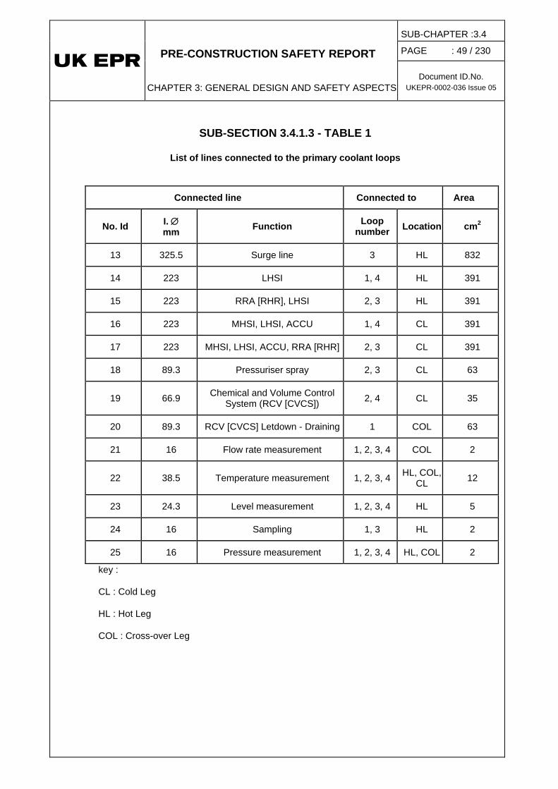
PRE-CONSTRUCTION SAFETY REPORT
CHAPTER 3: GENERAL DESIGN AND SAFETY ASPECTS
SUB-CHAPTER :3.4
PAGE : 49 / 230
Document ID.No. UKEPR-0002-036 Issue 05
SUB-SECTION 3.4.1.3 - TABLE 1
List of lines connected to the primary coolant loops
Connected line Connected to Area
No. Id I. ∅ mm Function Loop
number Location cm2
13 325.5 Surge line 3 HL 832
14 223 LHSI 1, 4 HL 391
15 223 RRA [RHR], LHSI 2, 3 HL 391
16 223 MHSI, LHSI, ACCU 1, 4 CL 391
17 223 MHSI, LHSI, ACCU, RRA [RHR] 2, 3 CL 391
18 89.3 Pressuriser spray 2, 3 CL 63
19 66.9 Chemical and Volume Control System (RCV [CVCS]) 2, 4 CL 35
20 89.3 RCV [CVCS] Letdown - Draining 1 COL 63
21 16 Flow rate measurement 1, 2, 3, 4 COL 2
22 38.5 Temperature measurement 1, 2, 3, 4 HL, COL, CL 12
23 24.3 Level measurement 1, 2, 3, 4 HL 5
24 16 Sampling 1, 3 HL 2
25 16 Pressure measurement 1, 2, 3, 4 HL, COL 2
key :
CL : Cold Leg
HL : Hot Leg
COL : Cross-over Leg

PRE-CONSTRUCTION SAFETY REPORT
CHAPTER 3: GENERAL DESIGN AND SAFETY ASPECTS
SUB-CHAPTER :3.4
PAGE : 50 / 230
Document ID.No. UKEPR-0002-036 Issue 05
SUB-SECTION 3.4.1.3 - TABLE 2
Initial conditions and limit conditions [Ref-1]
Initial conditions
Reactor at 100% power Stretch-out
Reactor power % 100 83.3
Pressure bar 157.1 1) 157.1 1)
Reactor inlet temperature °C 291.8 2) 276.8 2)
Reactor outlet temperature °C 325.25 2) 306.3 2)
Break conditions
Hot leg Cold leg
Break area cm2 837 2) 563 2)
Diameter mm 326.5 2) 267.7 2)
Distance from break to vessel m 4.31 2) 2.92 2)
Break opening rate linear linear
Break opening time ms 1 1
1) including uncertainties
2) preliminary values (decoupling values) used in the analyses

PRE-CONSTRUCTION SAFETY REPORT
CHAPTER 3: GENERAL DESIGN AND SAFETY ASPECTS
SUB-CHAPTER :3.4
PAGE : 51 / 230
Document ID.No. UKEPR-0002-036 Issue 05
SUB-SECTION 3.4.1.3 - TABLE 3
Main results [Ref-1]
Reactor at 100% power Stretch-out
Break Surge line RIS [SIS] line Surge line RIS [SIS]
line
Maximum mass flow at break opening (kg/s) 6469 7519 8171 8196
Maximum jet force (kN) 1811 1816 1939 1945
Maximum force (kN) 19572 19744 19495 19705

PRE-CONSTRUCTION SAFETY REPORT
CHAPTER 3: GENERAL DESIGN AND SAFETY ASPECTS
SUB-CHAPTER :3.4
PAGE : 52 / 230
Document ID.No. UKEPR-0002-036 Issue 05
SUB-SECTION 3.4.1.3 - TABLE 4
List of vertical and horizontal forces
Vertical forces : FV401 Force on the upper part of the core barrel (between the upper support plate and the flange) FV402 Force on the lower part of the core barrel FV403 Force on the core barrel flange FV404 Force on the core barrel bottom FV405 Force on the upper support plate FV406 Force on the bottom nozzle of the fuel assembly FV407 Force on the grids and guide tubes of the fuel assembly FV408 Force on the top nozzle of the fuel assembly FV409 Force on one fuel rod FV410 Force on the upper core plate FV411 Force on the upper support plate FV412 Force on the vessel head FV413 Force on the vessel lower plenum FV414 Force on the heavy reflector FV415 Total force on the lower internals (FV401+FV402+FV403+ FV404+FV405+ FV414+ FV417) FV416 Total force on the upper internals (FV410+FV411) FV417 Total force on the core (nfa * ( FV406+ FV407+ FV408 + nrod*FV409 )) FV418 Total force on the vessel and internals (FV412+FV413+FV415+FV416) Horizontal forces FH1/2 Force on the vessel inside surface (2.005 - 3.701 m) FH3/4 Force on the core barrel outside surface (2.005 - 3.701 m) FH5/6 Force on the vessel inside surface (3.701 - 5.538 m) FH7/8 Force on the core barrel outside surface (3.701 - 5.538 m) FH9/10 Force on the vessel inside surface (5.538 - 6.890 m) FH11/12 Force on the core barrel outside surface (5.538 - 6.890 m) FH13/14 Force on the vessel inside surface (6.890 - 8;580 m) FH15/16 Force on the core barrel outside surface (6.890 - 8.580 m) FH17/18 Force on the vessel inside surface (8.580 - 9.730 m) FH19/20 Force on the core barrel outside surface (8.580 - 9.730 m) FH21/22 Force on the upper plenum internals FH23/24 Force on the core barrel inside surface in the upper plenum
nfa .... number of fuel assemblies nrod .. number of fuel rods in a fuel assembly even number for horizontal forces ⇒ direction y odd number for horizontal forces ⇒ direction x

PRE-CONSTRUCTION SAFETY REPORT
CHAPTER 3: GENERAL DESIGN AND SAFETY ASPECTS
SUB-CHAPTER :3.4
PAGE : 53 / 230
Document ID.No. UKEPR-0002-036 Issue 05
SUB-SECTION 3.4.1.3 - TABLE 5
Initial conditions and boundary conditions [Ref-1]
INITIAL CONDITIONS
STRETCH-OUT
Reactor power 83.3%
Pressure 157.1 bar 1)
Vessel inlet temperature 276.8 °C
Vessel outlet temperature 306.3°C 2)
Temperature at the vessel upper dome inlet 276.8 °C
BREAK ASSUMPTIONS
Hot leg Cold leg
Connected line Surge line Safety injection line
Break area 837 cm2 2) 563 cm2 2)
Diameter 326.7 mm 2) 267.7 mm 2)
Distance break-vessel 5.34 m 2,3) 4.77 m 2,3)
Break opening linear linear
Break opening time 1 ms 1 ms
1) including uncertainties 2) decoupling values used in the analyses 3) distance between the inside of the barrel and the reactor vessel respectively

PRE-CONSTRUCTION SAFETY REPORT
CHAPTER 3: GENERAL DESIGN AND SAFETY ASPECTS
SUB-CHAPTER :3.4
PAGE : 54 / 230
Document ID.No. UKEPR-0002-036 Issue 05
SUB-SECTION 3.4.1.3 - TABLE 6
Maximum vertical and horizontal hydraulic forces [Ref-1]
Vertical forces surge line break safety injection line break(kN) (kN)
FV401 -0,85 -0,92FV402 -4,25 -3,67FV403 -12790 -14674FV404 13073 13073FV405 2605 2321FV406 0,38 0,31FV407 2,83 1,87FV408 0,34 0,27FV409 0,05 0,03FV410 984 886FV411 -6556 -7266FV412 300146 300146FV413 -305528 -305528FV414 1463 945,7FV415 9340 6441FV416 -5885 -6481FV417 3718 2489FV418 -3033 -3957
Horizontal forces surge line break safety injection line break(kN) (kN)
FH1 -688 -5266FH2 451 1809FH3 606 4639FH4 -397 -1594FH5 800 5167FH6 778 -2053FH7 -705 -4551FH8 -685 1808FH9 906 5148FH10 875 -1755FH11 -798 -4535FH12 -771 1546FH13 1627 7709FH14 1623 2463FH15 -1551 -7473FH16 -1631 -2251FH17 1257 6860FH18 1343 1854FH19 -1226 -6725FH20 -1385 -1714FH21 -2669 -421FH22 1130 418FH23 4421 733FH24 -1979 -638

PRE-CONSTRUCTION SAFETY REPORT
CHAPTER 3: GENERAL DESIGN AND SAFETY ASPECTS
SUB-CHAPTER :3.4
PAGE : 55 / 230
Document ID.No. UKEPR-0002-036 Issue 05
SUB-SECTION 3.4.1.3 - TABLE 7
Maximum forces and displacements on the most loaded upper internal equipment [Ref-1]
SURGE LINE BREAK (BAR)
SAFETY INJECTION LINE BREAK (BAR)
Upper support plate (vertical, bottom – top) -4.2 -4.6
Core barrel (horizontal, inside, outside) -12.1 -16.8
SURGE LINE BREAK SAFETY INJECTION LINE BREAK
FORCE DISPLACEMENT FORCE DISPLACEMENT
NO. (kN) (mm) NO. (kN) (mm)
CRGA GUIDE TUBE 15 119 4.784 15 28.5 1.138
CRGA GUIDE TUBE 14 110 4.393 8 25.9 1.099
SUPPORT COLUMN 1 13.6 2.823 102 3.45 2.298
SUPPORT COLUMN 4 12.3 2.099 4 3.34 1.302
SUPPORT COLUMN 3 24.1 6.083 3 5.92 1.453
SUPPORT COLUMN 9 21.2 5.941 9 5.45 2.093
LEVEL MEASUREMENT G. T. 43 9.51 1.365 97 2.23 1.043
LEVEL MEASUREMENT G. T. 97 4.34 1.126 43 1.58 0.449

PRE-CONSTRUCTION SAFETY REPORT
CHAPTER 3: GENERAL DESIGN AND SAFETY ASPECTS
SUB-CHAPTER :3.4
PAGE : 56 / 230
Document ID.No. UKEPR-0002-036 Issue 05
SUB-SECTION 3.4.1.3 - FIGURE 1
Model of one primary loop

PRE-CONSTRUCTION SAFETY REPORT
CHAPTER 3: GENERAL DESIGN AND SAFETY ASPECTS
SUB-CHAPTER :3.4
PAGE : 57 / 230
Document ID.No. UKEPR-0002-036 Issue 05
SUB-SECTION 3.4.1.3 - FIGURE 2
Model of the four primary loops

PRE-CONSTRUCTION SAFETY REPORT
CHAPTER 3: GENERAL DESIGN AND SAFETY ASPECTS
SUB-CHAPTER :3.4
PAGE : 58 / 230
Document ID.No. UKEPR-0002-036 Issue 05
SUB-SECTION 3.4.1.3 - FIGURE 3
Horizontal floor response spectrum [Ref-1]
Horizontal floor response spectrum - 19.5m - 4%
0,1
1
10
1 10 100
f(Hz)
pseu
do-a
cc. (
g)
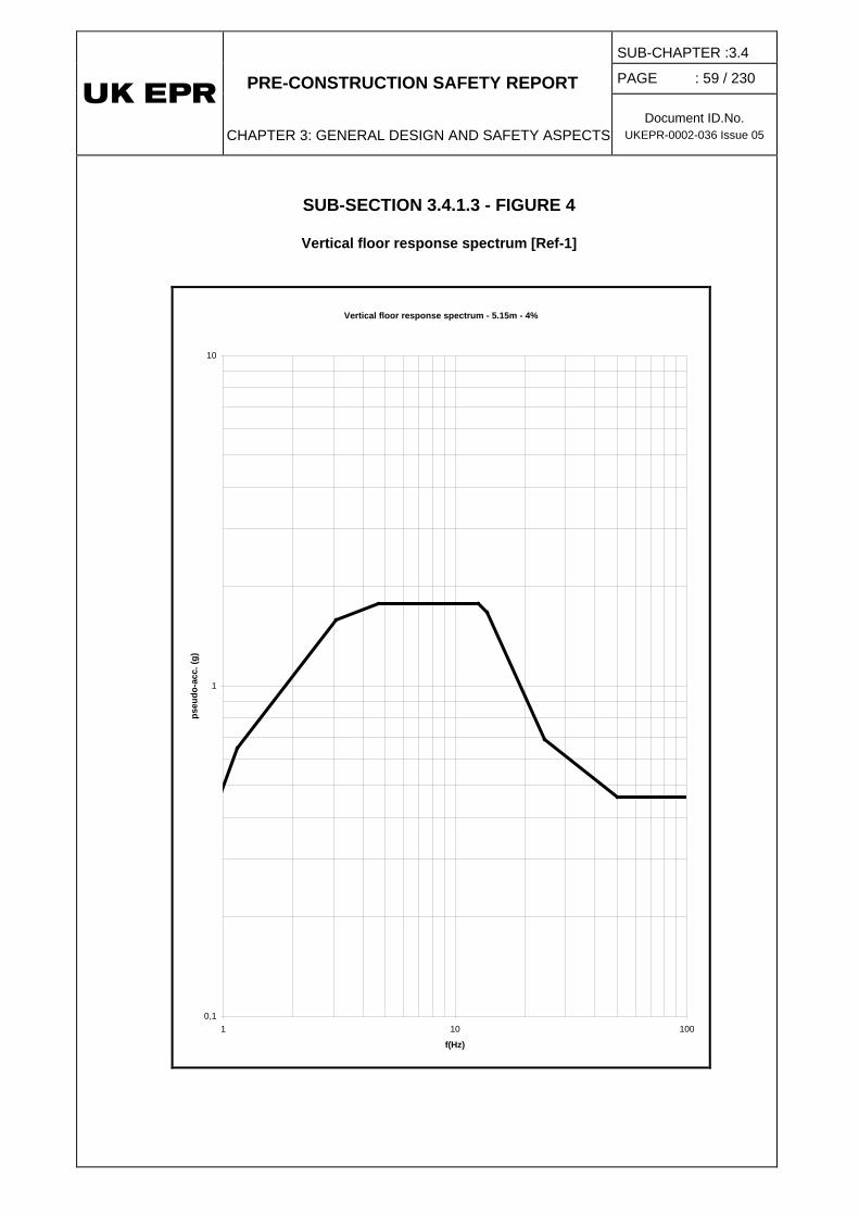
PRE-CONSTRUCTION SAFETY REPORT
CHAPTER 3: GENERAL DESIGN AND SAFETY ASPECTS
SUB-CHAPTER :3.4
PAGE : 59 / 230
Document ID.No. UKEPR-0002-036 Issue 05
SUB-SECTION 3.4.1.3 - FIGURE 4
Vertical floor response spectrum [Ref-1]
Vertical floor response spectrum - 5.15m - 4%
0,1
1
10
1 10 100
f(Hz)
pseu
do-a
cc. (
g)

PRE-CONSTRUCTION SAFETY REPORT
CHAPTER 3: GENERAL DESIGN AND SAFETY ASPECTS
SUB-CHAPTER :3.4
PAGE : 60 / 230
Document ID.No.UKEPR-0002-036 Issue 05
{CCI removed}

PRE-CONSTRUCTION SAFETY REPORT
CHAPTER 3: GENERAL DESIGN AND SAFETY ASPECTS
SUB-CHAPTER :3.4
PAGE : 61 / 230
Document ID.No.UKEPR-0002-036 Issue 05
{CCI removed}

PRE-CONSTRUCTION SAFETY REPORT
CHAPTER 3: GENERAL DESIGN AND SAFETY ASPECTS
SUB-CHAPTER :3.4
PAGE : 62 / 230
Document ID.No. UKEPR-0002-036 Issue 05
SUB-SECTION 3.4.1.3 - FIGURE 7
Surge line break Pressure upstream from the break and mass flow at the break for full power operating
conditions [Ref-1]
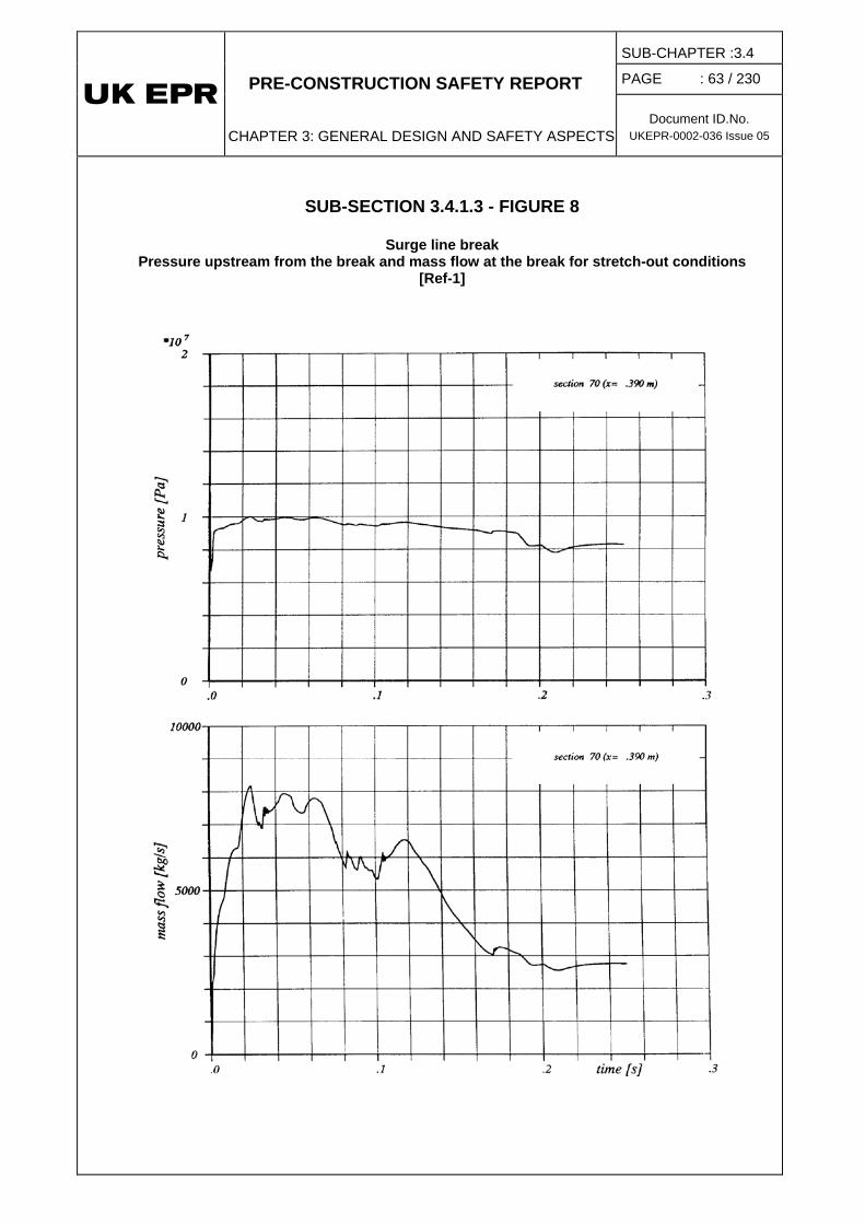
PRE-CONSTRUCTION SAFETY REPORT
CHAPTER 3: GENERAL DESIGN AND SAFETY ASPECTS
SUB-CHAPTER :3.4
PAGE : 63 / 230
Document ID.No. UKEPR-0002-036 Issue 05
SUB-SECTION 3.4.1.3 - FIGURE 8
Surge line break Pressure upstream from the break and mass flow at the break for stretch-out conditions
[Ref-1]

PRE-CONSTRUCTION SAFETY REPORT
CHAPTER 3: GENERAL DESIGN AND SAFETY ASPECTS
SUB-CHAPTER :3.4
PAGE : 64 / 230
Document ID.No. UKEPR-0002-036 Issue 05
SUB-SECTION 3.4.1.3 - FIGURE 9
Safety injection line break Pressure upstream from the break and mass flow at the break for full power operating
conditions [Ref-1]

PRE-CONSTRUCTION SAFETY REPORT
CHAPTER 3: GENERAL DESIGN AND SAFETY ASPECTS
SUB-CHAPTER :3.4
PAGE : 65 / 230
Document ID.No. UKEPR-0002-036 Issue 05
SUB-SECTION 3.4.1.3 - FIGURE 10
Safety injection line break Pressure upstream from the break and mass flow at the break for stretch-out conditions
[Ref-1]

PRE-CONSTRUCTION SAFETY REPORT
CHAPTER 3: GENERAL DESIGN AND SAFETY ASPECTS
SUB-CHAPTER :3.4
PAGE : 66 / 230
Document ID.No. UKEPR-0002-036 Issue 05
SUB-SECTION 3.4.1.3 - FIGURE 11
Maximum force comparison for cases A and B [Ref-1]

PRE-CONSTRUCTION SAFETY REPORT
CHAPTER 3: GENERAL DESIGN AND SAFETY ASPECTS
SUB-CHAPTER :3.4
PAGE : 67 / 230
Document ID.No.UKEPR-0002-036 Issue 05
{CCI removed}

PRE-CONSTRUCTION SAFETY REPORT
CHAPTER 3: GENERAL DESIGN AND SAFETY ASPECTS
SUB-CHAPTER :3.4
PAGE : 68 / 230
Document ID.No.UKEPR-0002-036 Issue 05
b
{CCI removed}

PRE-CONSTRUCTION SAFETY REPORT
CHAPTER 3: GENERAL DESIGN AND SAFETY ASPECTS
SUB-CHAPTER :3.4
PAGE : 69 / 230
Document ID.No. UKEPR-0002-036 Issue 05
SUB-SECTION 3.4.1.3 - FIGURE 14
Surge line break – pressure in the broken loop [Ref-1]
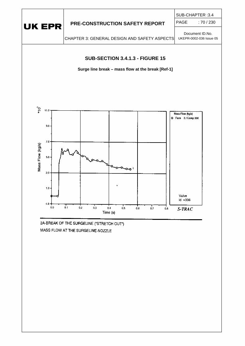
PRE-CONSTRUCTION SAFETY REPORT
CHAPTER 3: GENERAL DESIGN AND SAFETY ASPECTS
SUB-CHAPTER :3.4
PAGE : 70 / 230
Document ID.No. UKEPR-0002-036 Issue 05
SUB-SECTION 3.4.1.3 - FIGURE 15
Surge line break – mass flow at the break [Ref-1]

PRE-CONSTRUCTION SAFETY REPORT
CHAPTER 3: GENERAL DESIGN AND SAFETY ASPECTS
SUB-CHAPTER :3.4
PAGE : 71 / 230
Document ID.No. UKEPR-0002-036 Issue 05
SUB-SECTION 3.4.1.3 - FIGURE 16
Surge line break Radial velocity in the upper plenum (levels 8, 9) [Ref-1]

PRE-CONSTRUCTION SAFETY REPORT
CHAPTER 3: GENERAL DESIGN AND SAFETY ASPECTS
SUB-CHAPTER :3.4
PAGE : 72 / 230
Document ID.No. UKEPR-0002-036 Issue 05
SUB-SECTION 3.4.1.3 - FIGURE 17
Surge line break Radial velocity in the upper plenum (levels 10, 11) [Ref-1]

PRE-CONSTRUCTION SAFETY REPORT
CHAPTER 3: GENERAL DESIGN AND SAFETY ASPECTS
SUB-CHAPTER :3.4
PAGE : 73 / 230
Document ID.No. UKEPR-0002-036 Issue 05
SUB-SECTION 3.4.1.3 - FIGURE 18
Surge line break Applied force and displacement for the most highly loaded RCCA-guide [Ref-1]

PRE-CONSTRUCTION SAFETY REPORT
CHAPTER 3: GENERAL DESIGN AND SAFETY ASPECTS
SUB-CHAPTER :3.4
PAGE : 74 / 230
Document ID.No. UKEPR-0002-036 Issue 05
SUB-SECTION 3.4.1.3 - FIGURE 19
Surge line break Applied force and displacement for the most highly loaded support column [Ref-1]

PRE-CONSTRUCTION SAFETY REPORT
CHAPTER 3: GENERAL DESIGN AND SAFETY ASPECTS
SUB-CHAPTER :3.4
PAGE : 75 / 230
Document ID.No. UKEPR-0002-036 Issue 05
SUB-SECTION 3.4.1.3 - FIGURE 20
Surge line break Applied force and displacement for the most highly loaded level measurement guide tube
[Ref-1]
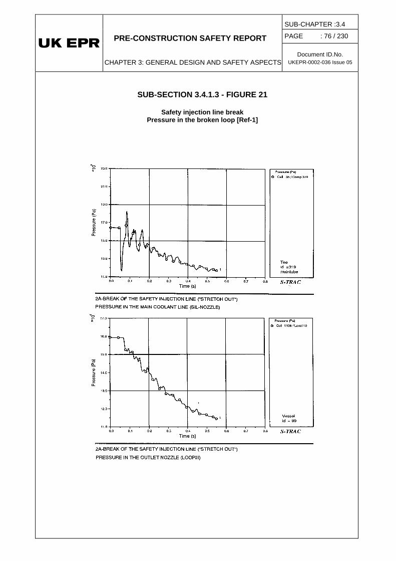
PRE-CONSTRUCTION SAFETY REPORT
CHAPTER 3: GENERAL DESIGN AND SAFETY ASPECTS
SUB-CHAPTER :3.4
PAGE : 76 / 230
Document ID.No. UKEPR-0002-036 Issue 05
SUB-SECTION 3.4.1.3 - FIGURE 21
Safety injection line break Pressure in the broken loop [Ref-1]
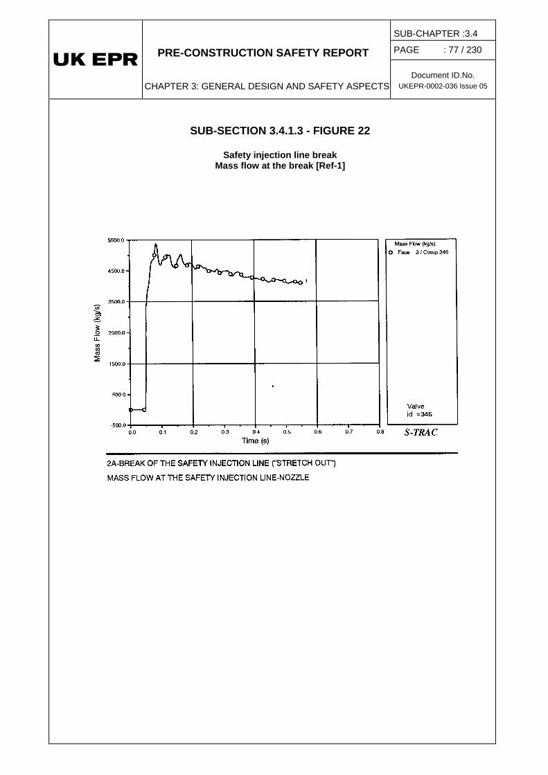
PRE-CONSTRUCTION SAFETY REPORT
CHAPTER 3: GENERAL DESIGN AND SAFETY ASPECTS
SUB-CHAPTER :3.4
PAGE : 77 / 230
Document ID.No. UKEPR-0002-036 Issue 05
SUB-SECTION 3.4.1.3 - FIGURE 22
Safety injection line break Mass flow at the break [Ref-1]

PRE-CONSTRUCTION SAFETY REPORT
CHAPTER 3: GENERAL DESIGN AND SAFETY ASPECTS
SUB-CHAPTER :3.4
PAGE : 78 / 230
Document ID.No. UKEPR-0002-036 Issue 05
SUB-SECTION 3.4.1.3 - FIGURE 23
Safety injection line break Radial velocity in the upper plenum (levels 8, 9) [Ref-1]

PRE-CONSTRUCTION SAFETY REPORT
CHAPTER 3: GENERAL DESIGN AND SAFETY ASPECTS
SUB-CHAPTER :3.4
PAGE : 79 / 230
Document ID.No. UKEPR-0002-036 Issue 05
SUB-SECTION 3.4.1.3 - FIGURE 24
Safety injection line break Radial velocity in the upper plenum (levels 10, 11) [Ref-1]

PRE-CONSTRUCTION SAFETY REPORT
CHAPTER 3: GENERAL DESIGN AND SAFETY ASPECTS
SUB-CHAPTER :3.4
PAGE : 80 / 230
Document ID.No. UKEPR-0002-036 Issue 05
SUB-SECTION 3.4.1.3 - FIGURE 25
Safety injection line break Applied force and displacement for the most highly loaded RCCA-guide [Ref-1]

PRE-CONSTRUCTION SAFETY REPORT
CHAPTER 3: GENERAL DESIGN AND SAFETY ASPECTS
SUB-CHAPTER :3.4
PAGE : 81 / 230
Document ID.No. UKEPR-0002-036 Issue 05
SUB-SECTION 3.4.1.3 - FIGURE 26
Safety injection line break Applied force and displacement for the most highly loaded support column [Ref-1]
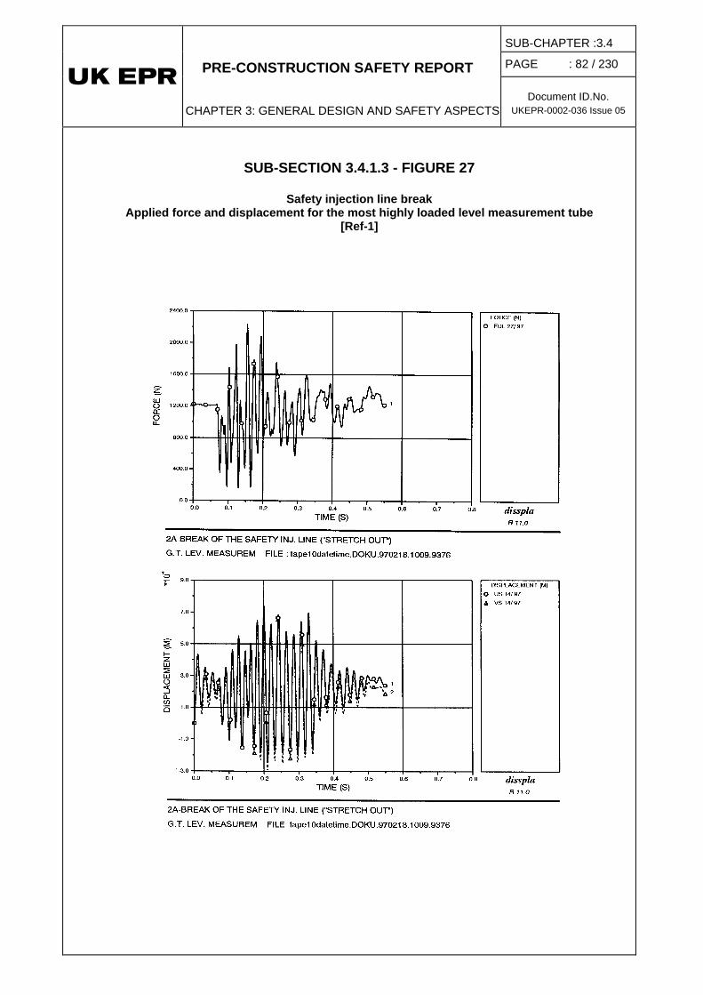
PRE-CONSTRUCTION SAFETY REPORT
CHAPTER 3: GENERAL DESIGN AND SAFETY ASPECTS
SUB-CHAPTER :3.4
PAGE : 82 / 230
Document ID.No. UKEPR-0002-036 Issue 05
SUB-SECTION 3.4.1.3 - FIGURE 27
Safety injection line break Applied force and displacement for the most highly loaded level measurement tube
[Ref-1]

PRE-CONSTRUCTION SAFETY REPORT
CHAPTER 3: GENERAL DESIGN AND SAFETY ASPECTS
SUB-CHAPTER :3.4
PAGE : 83 / 230
Document ID.No. UKEPR-0002-036 Issue 05
SUB-SECTION 3.4.1.3 - FIGURE 28
Total vertical force on the lower RPV internals [Ref-1]

PRE-CONSTRUCTION SAFETY REPORT
CHAPTER 3: GENERAL DESIGN AND SAFETY ASPECTS
SUB-CHAPTER :3.4
PAGE : 84 / 230
Document ID.No. UKEPR-0002-036 Issue 05
SUB-SECTION 3.4.1.3 - FIGURE 29
Total vertical force on the upper RPV internals [Ref-1]

PRE-CONSTRUCTION SAFETY REPORT
CHAPTER 3: GENERAL DESIGN AND SAFETY ASPECTS
SUB-CHAPTER :3.4
PAGE : 85 / 230
Document ID.No. UKEPR-0002-036 Issue 05
SUB-SECTION 3.4.1.3 - FIGURE 30
Total vertical force on the core [Ref-1]

PRE-CONSTRUCTION SAFETY REPORT
CHAPTER 3: GENERAL DESIGN AND SAFETY ASPECTS
SUB-CHAPTER :3.4
PAGE : 86 / 230
Document ID.No. UKEPR-0002-036 Issue 05
SUB-SECTION 3.4.1.3 - FIGURE 31
Total vertical force on the vessel and internals [Ref-1]

PRE-CONSTRUCTION SAFETY REPORT
CHAPTER 3: GENERAL DESIGN AND SAFETY ASPECTS
SUB-CHAPTER :3.4
PAGE : 87 / 230
Document ID.No. UKEPR-0002-036 Issue 05
SUB-SECTION 3.4.1.3 - FIGURE 32
Total force on the upper internals (direction X) [Ref-1]
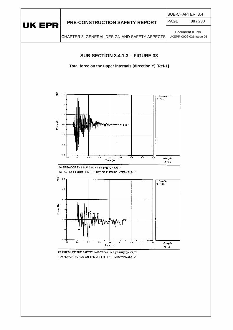
PRE-CONSTRUCTION SAFETY REPORT
CHAPTER 3: GENERAL DESIGN AND SAFETY ASPECTS
SUB-CHAPTER :3.4
PAGE : 88 / 230
Document ID.No. UKEPR-0002-036 Issue 05
SUB-SECTION 3.4.1.3 – FIGURE 33
Total force on the upper internals (direction Y) [Ref-1]

PRE-CONSTRUCTION SAFETY REPORT
CHAPTER 3: GENERAL DESIGN AND SAFETY ASPECTS
SUB-CHAPTER :3.4
PAGE : 89 / 230
Document ID.No. UKEPR-0002-036 Issue 05
SUB-SECTION 3.4.1.3 - FIGURE 34
Vertical pressure difference on the upper support plate [Ref-1]

PRE-CONSTRUCTION SAFETY REPORT
CHAPTER 3: GENERAL DESIGN AND SAFETY ASPECTS
SUB-CHAPTER :3.4
PAGE : 90 / 230
Document ID.No. UKEPR-0002-036 Issue 05
SUB-SECTION 3.4.1.3 - FIGURE 35
Horizontal pressure difference on the core barrel in the upper plenum [Ref-1]

PRE-CONSTRUCTION SAFETY REPORT
CHAPTER 3 : GENERAL DESIGN AND SAFETY ASPECTS
SUB-CHAPTER :3.4
PAGE : 91 / 230
Document ID.No. UKEPR-0002-036 Issue 05
1.4. HYDRAULIC LOADING IN THE CSP [SSPB] AFTER MAIN STEAM LINE BREAK (MSLB) AND FEEDWATER LINE BREAK (FWLB)
1.4.1. Description of phenomena
In the case of a double-ended break in a Main Steam Line (VVP) [MSSS] or a Feedwater Line (ARE) [MFWS], the pressure at the break falls instantaneously, while the flow rate at that point reaches a high value. A wave front forms at the break and propagates in one direction towards the Steam Generator (SG) and in the other direction towards the turbine or the ARE [MFWS] reservoir. A system decompression follows and the fluid accelerates in the line.
1.4.2. Break assumptions
The Secondary System pipework includes the Main Steam System pipework, part of which is HIC1
Main steam pipes:
, and the Main Feedwater System pipework.
• Inside the containment:
The main section of the SG steam line between the SG outlet and the anchor for the containment penetration is HIC and no break is considered in this area.
• Outside the containment, upstream of the fixed point of the main steam lines:
The SG steam pipework in the section of the VVP [MSSS] located between the reactor building penetration and the fixed point of the main steam lines is also HIC and no break is considered in this area. It includes the three most important connections, the VDA [MSRT] connection and the two connections for the main steam safety valves. The latter are extruded fittings with the valves mounted directly on them (no pipe between the fitting and the valve).
The remaining pipework, such as the VIV [MSIV] bypass-line and its two branch connections, and the VDA [MSRT] and VVP [MSSS] pipework downstream of the valve is not considered to be HIC.
• Outside the containment, downstream of the fixed point of the main steam lines:
The HIC claim does not apply.
ARE [MFWS] pipes:
• Inside the containment:
The HIC claim does not apply.
1 Although the MSL are designated as HIC for the UK EPR and the associated requirements
are described in Sub-chapter 3.4, additional conservative risk reduction measures which are inherent to the break preclusion concept are described in Sub-chapter 10.5.

PRE-CONSTRUCTION SAFETY REPORT
CHAPTER 3 : GENERAL DESIGN AND SAFETY ASPECTS
SUB-CHAPTER :3.4
PAGE : 92 / 230
Document ID.No. UKEPR-0002-036 Issue 05
• Outside the containment:
The HIC claim does not apply.
1.4.3. Design breaks
The HIC claim means that a break in the SG steam pipes is considered only to occur downstream of the fixed point of the main steam lines, whereas a break in the ARE [MFWS] line may occur anywhere.
Despite this HIC designation for the UK EPR, which applies to the connections for the VDA [MSRT] and the main steam safety valves, rupture of the connecting pipes is considered and studied using realistic assumptions as an additional conservative measure. The limiting breaks taken into account in the mechanical design are therefore:
For the main steam pipes:
• a double-ended break in the steam pipes downstream of the fixed point of the main steam lines, or
• a rupture of the VIV [MSIV] by-pass line, or
• a rupture of the VDA [MSRT] connection (with realistic assumptions), or
• a rupture of a main steam safety valve connection (with realistic assumptions).
These last three breaks do not require transient calculation to determine the induced hydraulic loading because an increasing static loading is taken into account [Ref-1]. The remainder of this section therefore makes no reference to these breaks.
Pipes in the main feedwater system
• double-ended break in the ARE [MFWS] line.
1.4.4. Analysis method
• Analysis of depressurisation in the CSP [SSPB]
This transient is studied using a code which models the time variation of the fluid thermal-hydraulic parameters during depressurisation of the CSP [SSPB] (ROLAST code for example). In the model, hydrodynamics equations for a homogeneous fluid in a network of one-dimensional interconnected pipes are solved by the method of the characteristics.
• Calculation of hydraulic loads:
The calculation provides the time dependent functions of pressure, flow velocity and mass flow. As basis for the structural dynamic calculation, the fluid forces for all relevant pipe sections and the reaction force at the break location are calculated.

PRE-CONSTRUCTION SAFETY REPORT
CHAPTER 3 : GENERAL DESIGN AND SAFETY ASPECTS
SUB-CHAPTER :3.4
PAGE : 93 / 230
Document ID.No. UKEPR-0002-036 Issue 05
1.4.5. Hydraulic loading after MSLB
The analysis has three objectives:
• justification of the pipe strength,
• justification of the MSL supports,
• demonstration of the Break Preclusion assumption.
Specific assumptions
Depending on the objective of the calculation, the assumptions applied may be different. Only normal operation has to be considered.
Choice of line modelled
The main steam lines for steam generators SG 01 and SG 02 are identical to the steam lines for steam generators SG 04 and SG 03 respectively.
The SG steam lines differ only outside the reactor building; the lines inside the reactor building are all identical. The steam line for the SG 01 (and SG 04) is slightly longer than the steam line for SG 02 (and SG 03) in the area between the reactor building penetration and the fixed point of the main steam lines.
As a result, the hydraulic loadings are slightly higher for SG 01 (and SG 04). The study models the SG 01 (or SG 04) steam line.
Modelling the main steam lines
The following elements are modelled for each of the bounding lines:
• the SG steam dome (modelled as a volume at constant pressure),
• the flow restrictor at the SG outlet,
• the main steam line up to the fixed point of the main steam line (downstream of the VIV [MSIV]),
• the elbows in the main steam line inside the Reactor Building,
• the elbows in the main steam line outside the Reactor Building,
Position of the break
A break round the full circumference of the main SG steam pipe is considered at the level of the fixed point of the main steam line outside the safeguard building.
Modelling the break
The model considers a double-ended break. The cross-section of the break is that of the internal cross-section of the steam line at each broken end.

PRE-CONSTRUCTION SAFETY REPORT
CHAPTER 3 : GENERAL DESIGN AND SAFETY ASPECTS
SUB-CHAPTER :3.4
PAGE : 94 / 230
Document ID.No. UKEPR-0002-036 Issue 05
Initial conditions
The higher the initial SG saturation pressure, the higher the initial hydraulic loads in the main steam lines. In order to obtain the maximum loads on the pipework, the initial conditions taken into account correspond to the reactor at low power during normal operation.
At power operation during normal operation, the SG saturation pressure is higher than in stretch-out operation. Accordingly, the stretch-out operating conditions are enveloped by the normal operating conditions.
1.4.6. Hydraulic loading after FWLB
The objective is the justification of the integrity of the steam generator internals.
Specific assumptions
Only normal operation has to be considered.
Choice of line modelled
The ARE [MFWS] lines for SG 01 and SG 02 are identical to those for SG 04 and SG 03 respectively.
The ARE [MFWS] line for SG 02 (and SG 03) is slightly longer than the ARE [MFWS] line for SG 01 (and SG 04) inside the Reactor Building. The difference is less than 4% of the total length of the ARE [MFWS] line within the Reactor Building.
Thus the hydraulic loads are slightly higher for SG 02 (and SG 03). The study models the ARE [MFWS] line for SG 02 (or SG 03).
Modelling the ARE [MFWS] line
For all the breaks considered, the following elements are modelled for the SG 02 line:
• the secondary side of the Steam Generator
• the half feedwater distribution ring and the deflecting sheet forming the junction with the SG, characterised by the fluid sections, the pressure loss coefficients and the fluid lengths,
• the SG inlet nozzle,
• the check valve near the SG
• the main feedwater line inside the Reactor Building, from the SG inlet nozzle up to the reactor containment penetration.
Location of breaks
Circumferential breaks in the main feedwater line are considered. The piping lengths upstream and downstream of the break form a double-ended break. A rupture at each weld has to be considered between the SG and the containment penetration, and one additional rupture adjacent to the control valve station.
PRE-CONSTRUCTION SAFETY REPORT
CHAPTER 3 : GENERAL DESIGN AND SAFETY ASPECTS
SUB-CHAPTER :3.4
PAGE : 95 / 230
Document ID.No. UKEPR-0002-036 Issue 05
Modelling the break
The model considers a double-ended guillotine break. The break area used is equal to the piping internal cross-sectional area at each broken end.

PRE-CONSTRUCTION SAFETY REPORT
CHAPTER 3 : GENERAL DESIGN AND SAFETY ASPECTS
SUB-CHAPTER :3.4
PAGE : 96 / 230
Document ID.No. UKEPR-0002-036 Issue 05
1.5. OVERPRESSURE PROTECTION ANALYSES
1.5.1. Introduction
This section presents "Overpressure Protection analyses" (OPP) covering the overpressure criteria applicable in the analysis of PCC accidents (Chapter 14) and RRC-A sequences (Chapter 16). In summary:
• PCC-2, PCC-3, PCC-4 accidents are encompassed, in terms of primary and secondary overpressure transients, by the Category 3 OPP analyses. Component integrity with respect to overpressure is ensured by Reactor Trip (RT) and the Safety Valves (SV) alone (which are F1A classified). These functions limit the overpressure peak to below the overpressure criteria (110% DP with RT + (N) SV and 120% DP with RT + (N-1)1
(It should be noted that the overpressure criterion applied in PCC-4 accidents is the same as that for Category 4 OPP conditions (decoupling value: 130% DP): this criterion is also used for RRC-A sequences. The overpressure criterion for Category 3 OPP conditions is actually specified, since no PCC-4 transient results in an overpressure greater than that in the bounding PCC-3 transient.)
SV), for the most limiting PCC event (inadvertent closure of all VIV [MSIV] at full power), assuming the same conservative boundary conditions used in PCC analyses (with regard to initial conditions, and RT and SV characteristics). (N is the number of safety valves available for the event and DP is the design pressure).
• RRC-A sequences are either identical or bounded, in terms of primary and secondary overpressure transients, by the Category 4 OPP analyses. Component integrity with respect to overpressure is ensured by the effective action of the pressuriser spray and relief / safety valves (PSV, GCT [MSB], VDA [MSRT], MSSV) along with dedicated ATWS actions2
Demonstration of the effectiveness of overpressure protection in PCC and RRC-A accidents is not addressed in Chapters 14 and 16, as it is demonstrated by the overpressure analyses in the present sub-chapter.
(which all are F2 / F1 classified for RRC-A analyses). These features limit the peak overpressure to below the overpressure criteria (130% DP acceptance limit), for the most limiting RRC-A event (ATWS caused by stuck rods), under the set of boundary conditions applicable in RRC-A analyses (realistic approach, except dedicated ATWS actions are treated pessimistically).
1 The most limiting single failure assumed in OPP analyses is the failure of one safety valve to open.
Preventive maintenance is not performed on safety valves and has no consequences for reactor trip. Note: No credit is taken for the VDA [MSRT], (F1A classified), in Category 3 OPP analyses, resulting in a pessimistic calculation of peak overpressure.
2 Dedicated ATWS actions: - ATWS caused by stuck rods: ATWS signal on "RT signal + rods out or flux high" . RBS [EBS] immediate actuation . VCT (Volume Control Tank) isolation . All reactor coolant pumps trip on "SG level < MIN2" - ATWS by RT signal failure: RT / TT signal (outside the PS) on "SG level < MIN3" These actions prevent SG dryout with core power remaining high. They provide generic protection
against excessive RCP [RCS] overpressure for the most limiting events with failure of reactor trip. ("ATWS caused by stuck rods" is more limiting than "ATWS by RT signal failure").

PRE-CONSTRUCTION SAFETY REPORT
CHAPTER 3 : GENERAL DESIGN AND SAFETY ASPECTS
SUB-CHAPTER :3.4
PAGE : 97 / 230
Document ID.No. UKEPR-0002-036 Issue 05
The design of the overpressure protection equipment complies with the European requirements which are summarised as follows:
• The capacity of the set of safety devices of proven high-reliability to limit the pressure reached during Category 2 situations to 100% of the design pressure, and to avoid loss of integrity from equipment overpressure in Category 4 situations.
• The capacity of these safety devices alone, acting directly to limit the pressure, to restrict the pressure in Category 3 situations to 110% of the design pressure.
• The capacity of the same devices (with one of them, if fewer than four, or two of them, if four or more, being considered unavailable) to restrict the pressure in Category 3 situations to 120% of the design pressure.
These requirements cover those in the European Directive PED CE/97/23 [Ref-1] as well as those in RCC-M Ed 2007 [Ref-2], which require that the maximum admissible pressure is not exceeded in circumstances which can reasonably be foreseen. Since the maximum admissible pressure for each item of equipment is its design pressure, this requirement complies with the criteria for Category 2 situations (situations affecting equipment which is designed for use when the plant is in normal operation).
1.5.2. Analyses of overpressure protection at power
The following are defined for each category of operating condition:
• The overpressure protection criterion: this defines the overpressure limits that must not be exceeded.
• The means of protecting against overpressure: these are the devices provided to reduce overpressure in order to comply with the overpressure protection criterion.
• The overpressure protection analysis rules: these define the boundary conditions used in the analysis of overpressure transients, carried out to demonstrate that the overpressure protection criterion is satisfied.
Section 3.4.1.5 - Table 1 defines, for each category, the respective OPP criterion, method of OPP protection, and the associated OPP analysis rules. In addition, the most limiting condition for each category is specified. Both primary and secondary OPP are included.
The new reference configuration uses SEMPELL Pressuriser Safety Valves (previously SEBIM Pressuriser Safety Valves were used). This implies a change in the setpoint for the opening of the PSV and in the maximum stroke time (which is reduced from 1.5 seconds to 0.1 seconds and is therefore less onerous). Thus, the overpressure results are affected. The analysis of this impact is given hereafter, on the basis of the previous studies.
1.5.2.1. Primary side overpressure protection analyses
Primary side overpressure protection (OPP) addresses the mechanical design of the Reactor Coolant System. Three different categories of loading conditions are defined, involving different OPP criteria, OPP methods, and OPP analysis rules (Section 3.4.1.5 - Table 1).

PRE-CONSTRUCTION SAFETY REPORT
CHAPTER 3 : GENERAL DESIGN AND SAFETY ASPECTS
SUB-CHAPTER :3.4
PAGE : 98 / 230
Document ID.No. UKEPR-0002-036 Issue 05
• In Category 2:
o the OPP criterion is 100% DP, with brief overshoot above the design pressure (< 105% DP) accepted,
o credit is taken for all OPP systems, including controls, limitation and protection features,
o in OPP transient analyses, uncertainties in boundary conditions which have a significant impact on the overpressure peak are considered. No failures are postulated.
• In Category 3:
o the OPP criterion is 110% DP with all safety valves operable (N SV), and 120% DP with one valve inoperable (N-1 SV). These OPP criteria apply to a design with N < 4, with respect to the reactor coolant system,
o only the safety valves (SV), and a reactor trip (RT) actuated by the reactor Protection System (RPR [PS]) are claimed,
o in OPP transient analyses, conservative assumptions are applied to all boundary conditions in a deterministic way. No failures are postulated (except 1 SV for 120% DP criterion).
• In Category 4:
o the OPP criterion is the preservation of Reactor Coolant System integrity. A peak pressure not exceeding 130% DP is the acceptance criterion applied in the assessment,
o all OPP systems are claimed, including controls, limitations and protection functions, (except those already inoperable as defined for the "multiple event sequence" under consideration),
o in OPP transient analyses, realistic assumptions are applied. No failures are postulated (except those already involved in the "multiple event sequence" under consideration).
1.5.2.1.1. Category 2
a) Criterion
In Category 2, the pressure at the most loaded point of the RCP [RCS] should not exceed 100% DP (176 bar), but a brief overshoot is accepted. The overpressure3
3 Note: PSVs are intentionally disregarded in demonstrating the 100% DP criterion. Not claiming the
PSV in such events allows their pressure setpoints to be increased, giving positive consequences for safety. Thus, the probability of a challenge to the PSVs (with consequential release of radioactive coolant) is reduced in overpressure transients where PSVs are not strictly needed.
is limited by the

PRE-CONSTRUCTION SAFETY REPORT
CHAPTER 3 : GENERAL DESIGN AND SAFETY ASPECTS
SUB-CHAPTER :3.4
PAGE : 99 / 230
Document ID.No. UKEPR-0002-036 Issue 05
pressuriser normal spray, GCT [MSB], partial trip4
b) Design condition
and reactor trip. This OPP criterion must be fulfilled taking account of uncertainties, but without postulating an additional failure.
The most limiting operational transients are:
• Load rejection with transfer to house load.
• Grid fault.
The most limiting anticipated operational occurrences are:
• Loss of one main feedwater pump.
• Turbine trip.
• Short-term loss of offsite power.
In all of these conditions, a partial trip would be implemented at power levels above 60% of full power. This means that the nuclear power would be quickly reduced to about 50% full power by the dropping of a number of control rods. To be conservative, the partial trip is not claimed in the OPP analysis.
The most limiting Category 2 condition with respect to the primary overpressure peak is "short-term loss of offsite power at full power" [Ref-1].
c) Method of analysis
The transient analysis for "short-term loss of offsite power at full power" is performed using the MANTA V3.7 code [Ref-2] (Appendix 14A).
Uncertainties in significant boundary conditions were conservatively allowed for as follows:
• Most relevant plant initial conditions are maximised or minimised, depending on their effects.
• A point-kinetics model is used, with conservative core neutronic data bounding the different fuel management schemes.
• The performance of the systems involved in overpressure peak limitation is minimised, including assumptions of maximum delay in actuation and minimum pressure reducing capacity. These systems include:
o normal pressuriser spray,
o the GCT [MSB] (operable only during the first 10 seconds of the transient). The GCT [MSB] and the associated I&C are designed to ensure 10 seconds of steam relief before the setpoint is reached for GCT [MSB] isolation on high condenser pressure for the case loss of offsite power resulting in a loss of condenser vacuum,
4 Partial trip is not credited in the present Category 2 calculation.

PRE-CONSTRUCTION SAFETY REPORT
CHAPTER 3 : GENERAL DESIGN AND SAFETY ASPECTS
SUB-CHAPTER :3.4
PAGE : 100 / 230
Document ID.No. UKEPR-0002-036 Issue 05
o reactor trip (actuated on "low reactor coolant pumps speed"). Maximum decay heat is considered following the RT b - see Sub-chapter 14.1.
The major assumptions for the event are summarised in Section 3.4.1.5 - Table 9.
Note that the impact of an increase of the initial pressuriser level is assessed in section 1.5.2.1.1.d below.
d) Results [Ref-3]
A loss of offsite power leads to a trip of all reactor coolant pumps, a turbine trip and loss of main feedwater flow. Therefore, the primary and secondary pressures increase. The pressuriser normal spray is actuated and the GCT [MSB] valves open due to increased SG pressure. In conjunction with the reactor trip (actuated on "low reactor coolant pumps speed" signal), the pressuriser normal spray and GCT [MSB] terminate the primary and secondary pressure increases. The sequence of events is given in Section 3.4.1.5 - Table 10.
Section 3.4.1.5 - Figure 1 shows the development of the main parameters during the transient. The maximum pressure at the most loaded point of the RCP [RCS] (outlet) is 173.2 bar abs. (98.4% DP) in the most limiting Category 2-condition of "short term loss of offsite power at full power". This value is lower than 100% DP (176 bar).
Modifications to the PSVs do not affect this transient because the overpressure peak is lower than the threshold of opening of the first PSV.
A further decrease in the initial pressuriser level would have no significant impact on the maximum pressure. The pressure increase has a very fast dynamic, and a slightly lower initial pressuriser level would have no impact on such a fast phenomenon.
Therefore the Category 2 overpressure criterion is met.
1.5.2.1.2. Category 3
a) Criterion
In Category 3, the pressure at the most loaded point of the RCP [RCS] must not exceed:
110% DP (193.5 bar abs.), assuming three PSVs operable (no failure of a PSV).
120% DP (211.0 bar abs.), assuming two PSVs operable (failure of one PSV).
The overpressure is limited by the PSVs, the MSSVs, and reactor trip (actuated by the reactor Protection System). The OPP criteria must be fulfilled on a conservative deterministic basis with no additional failures (except one PSV for the 120% DP condition).
b) Design condition
The most limiting Category 3 condition with respect to the primary side overpressure peak is “inadvertent closure of all VIV [MSIV] at full power" [Ref-1].
{CCI removed}

PRE-CONSTRUCTION SAFETY REPORT
CHAPTER 3 : GENERAL DESIGN AND SAFETY ASPECTS
SUB-CHAPTER :3.4
PAGE : 101 / 230
Document ID.No. UKEPR-0002-036 Issue 05
c) Method of analysis
The transient analysis of "inadvertent closure of all VIV [MSIV] at full power" is performed using the MANTA V3.7 code (Appendix 14A). Conservative assumptions are made for each boundary condition that have a significant impact on the primary pressure peak, as follows:
Plant initial conditions are maximised or minimised, depending on their effects.
A point-kinetics model is used, with conservative core neutronic data bounding the different fuel management schemes.
The overpressure protection systems are limited to the PSVs, MSSVs and reactor trip. Performance data are pessimised, e.g. actuation time delay and pressure reducing capacity.
Reactor trip occurs on "pressuriser pressure high" signal, which provides primary overpressure protection. Maximum decay heat is considered
b (Sub-chapter 14.1).
The MSSVs are assumed to be actuated at their maximum opening pressure setpoint. However, this does not have any impact on the peak primary pressure.
The major assumptions for this event are summarised in Section 3.4.1.5 - Table 11.
Note that the impact of an increase of the initial pressuriser level is assessed in section 1.5.2.1.2.d below.
d) Results [Ref-2]
Following the closure of all VIV [MSIV], the primary side pressure increases rapidly due to the loss of the heat removal. The pressuriser pressure reaches the reactor trip setpoint ("high pressuriser pressure signal"), and then the first PSV (if claimed) and second / third PSV opening setpoints.
The MSSVs open after the primary pressure peak and thus do not contribute to the primary overpressure protection. The sequence of events is given in Section 3.4.1.5 - Table 12.
Section 3.4.1.5 - Figure 2 shows the development of the main parameters in the transient with three PSVs operable (no PSV failure). Section 3.4.1.5 - Figure 3 shows the development of the main parameters in the transient with two PSVs operable (failure of the first PSV).
The maximum pressure at the most loaded point of the RCP [RCS] (outlet) is 190.8 bar abs. (108.4% DP) in the most limiting Category 3 condition corresponding to "closure of all VIV [MSIV] at full power, with three PSVs operable" (no failure of a PSV). This value is lower than 110% DP (193.5 bar abs.).
{CCI removed}

PRE-CONSTRUCTION SAFETY REPORT
CHAPTER 3 : GENERAL DESIGN AND SAFETY ASPECTS
SUB-CHAPTER :3.4
PAGE : 102 / 230
Document ID.No. UKEPR-0002-036 Issue 05
The type of PSV has been changed to the SEMPELL valve and the first PSV opens 1 bar higher than the SEBIM valve but, instantaneously, it discharges more than 80 kg/sec. Due to the first PSV opening, the overpressure peak is curtailed because, before reaching the opening of the second PSV (which has the same setpoint as the SEBIM valve), the flow in the first valve has already started to decrease (see Section 3.4.1.5 - Figure 2). The third valve also opens, but the pressure peak is sufficiently reduced for the overpressure not to exceed the criterion. The pressure peak has already been reached before the second and third PSVs start to open. Additionally, considering the pressure rise transient, the first PSV opens 1 bar higher but the opening time is close to zero and consequently the SEMPELL PSV will have a negligible impact on overpressure peak. Therefore, the Category 3 OPP criterion is fulfilled.
The maximum pressure at the most loaded point of the RCP [RCS] (outlet) is 193.7 bar abs (110.1% DP) in the most limiting Category 3 condition corresponding to “closure of all VIV [MSIV] at full power, with two PSVs operable (failure of the first PSV)”. This value is lower than 120% DP (211 bar abs.). With the first PSV inoperable, the second PSV opens at the same pressure as the second SEBIM PSV, but with an opening time close to zero; therefore, this case will be less onerous. There is no problem with respect to the criterion because the overpressure peak is well below the criterion (211 bar abs.). Therefore the Category 3 OPP criterion is fulfilled.
Note that a further decrease in the initial pressuriser level would have no significant impact on the maximum pressure. The pressure increase has a very fast dynamic and a slightly lower initial pressuriser level would have no impact on such a fast phenomenon. The Category 3 OPP criterion would still be fulfilled.
1.5.2.1.3. Category 4
a) Criterion
In Category 4, the overpressure criterion is the preservation of Reactor Coolant System integrity. In accordance with the acceptance criterion, the pressure at the most loaded point of the RCP [RCS] should not exceed 130% DP (228.5 bar abs.). All the overpressure reducing systems are assumed to operate except those already considered as inoperable in the defining the multiple event sequence under consideration. In demonstrating the fulfilment of this criterion, the analysis is performed using realistic assumptions, without consideration of any additional failures.
b) Design condition
The most limiting Category 4 condition with respect to primary side overpressure peak is "excessive increase of secondary side steam flow at full power, without RT", defined as a spurious opening of the GCT [MSB] at full power, with mechanical sticking of the shutdown rods (ATWS by stuck rods).
c) Method of analysis
The transient analysis of "excessive increase in secondary side steam flow at full power, without RT" is performed (Sub-chapter 14.3) using the coupled MANTA V3.7, SMART V4.5, and FLICA IIIF V3 codes [Ref-1] [Ref-2] [Ref-3] (Appendix 14A).
Realistic assumptions are applied for the analysis:
• Realistic plant initial conditions are assumed.

PRE-CONSTRUCTION SAFETY REPORT
CHAPTER 3 : GENERAL DESIGN AND SAFETY ASPECTS
SUB-CHAPTER :3.4
PAGE : 103 / 230
Document ID.No. UKEPR-0002-036 Issue 05
• A 3D core calculation is performed using core neutronic data which is bounding for 100% of plant lifetime.
• Reactor trip is not claimed due to the assumptions of sticking of the rods.
• The overpressure reducing systems assumed operable are the pressuriser normal spray, PSV, GCT [MSB], VDA [MSRT] and MSSV. However, the GCT [MSB] is rapidly isolated and the MSSV open too late to affect the pressure peak.
• The ATWS signal and associated actions are assumed to be effective. These functions prevent SG dryout at high core power, limiting excessive RCP [RCS] overpressure.
The ATWS signal is triggered on "RT signal + rods out or flux high". The associated actions are immediate RBS [EBS] actuation, VIV [MSIV] isolation, all reactor coolant pumps turned-off on "SG level < MIN2".
The major assumptions are summarised on Section 3.4.1.5 - Table 13.
Calculations are performed for the EPR4250. The justification for EPR4500 (applicable to the UK EPR) is deduced from the results of the calculation.
Note that the impact of an increase of the initial pressuriser level is assessed in section 1.5.2.1.3.e below.
d) Results for EPR4250 [Ref-4]
Inadvertent opening of the GCT [MSB] leads to secondary side depressurisation. On generation of the signal "main steam pressure drop > MAX1", the VIVs [MSIVs] are closed, and the ARE [MFWS] full-load lines are isolated. The primary side overcooling leads to a core power increase. The maximum core power reached is 105.1% NP at time t = 16 seconds.
Following the VIV [MSIV] and ARE [MFWS] full-load line isolation, the primary side heats up (failure of RT), resulting in a primary side pressure increase. The primary coolant temperature increase leads to a core power decrease.
PSV opening at time t = 24.0 seconds (first PSV) and 25.7 seconds (second and third PSV), combined with the VDA [MSRT] challenge at time t = 24.5 seconds terminate the primary side overpressurisation.
All reactor coolant pumps are tripped at time t = 176.5 seconds on generation of the ATWS signal and SG level MIN2 signals, which significantly reduces the core power level at the SG dryout condition and avoids a second RCP [RCS] overpressure peak. Core boration by the RBS [EBS] starts after the occurrence of the overpressure peak. The sequence of events is given in Section 3.4.1.5 - Table 14.
Section 3.4.1.5 - Figure 4 shows the development of the main parameters during the transient. The maximum primary pressure at the most loaded point of the RCP [RCS] is 187.2 bar abs. (106.4% DP) for the most limiting Category 4 condition "excessive increase of secondary side steam flow at full power, without RT". The pressure peak is lower than 130% DP (228.5 bar abs.).
Therefore, the Category 4 OPP criterion is fulfilled.

PRE-CONSTRUCTION SAFETY REPORT
CHAPTER 3 : GENERAL DESIGN AND SAFETY ASPECTS
SUB-CHAPTER :3.4
PAGE : 104 / 230
Document ID.No. UKEPR-0002-036 Issue 05
e) Transposition of the EPR4250 results to EPR4500
The differences between the EPR4250 and EPR4500 cases are the following:
• The nominal power is increased by 6%.
• The primary side average temperature is increased by 1°C.
Discharge systems capacities and setpoints are identical in EPR4250 and EPR4500 cases.
Significant margins to the limits according to the EPR4250 analysis results:
• Primary pressure increase due to the event is 32.2 bar (pressure peak 187.2 bar).
• The margin to the 130% DP, (228.5 bar) criterion is 41.3 bar.
The penalties due to increasing to the EPR4500 power and primary average temperature condition are not sufficient to offset the margin in EPR4250 calculations. Indeed a power increase from 4250 to 4500 MW leads to a primary pressure increase of less than 1.5 bar for Category 2 and 3 transients.
The modification of the setpoint of the new PSV will have very little impact on the result because the higher setpoint is compensated for by the opening time of the valve which is close to zero. If the overpressure peak increases, the increase will be less than 1.5 bar; the Category 4 overpressure criteria are fulfilled for the EPR4500 case.
A further decrease in the initial pressuriser level would have very little impact on the result. The margins regarding the acceptance criteria are large enough to absorb the consequences of a potential pressure increase due to the increased initial pressuriser level uncertainties.
1.5.2.2. Secondary side overpressure protection analyses
Secondary side overpressure protection (OPP) analysis addresses the mechanical design of the main secondary systems. The secondary side OPP is divided into three different categories loading conditions categories, involving different OPP criteria, OPP methods, and OPP analysis rules (Section 3.4.1.5 - Table 1).
• In Category 2:
o the OPP criterion is 100% DP, with a short overshoot accepted (< 105% DP),
o credit is taken for all OPP systems, including control, limitation and protection functions,
o in the OPP transient analysis, uncertainties are taken into account on all boundary conditions which have a significant impact on the overpressure peak. No additional failures are postulated for this Category.
• In Category 3:
o the OPP criterion is 110% DP with all safety valves operable (N SV), and 120% DP with one inoperable valve (N-1 SV). These OPP criteria apply to a design with N < 4 safety valves in each main secondary system),

PRE-CONSTRUCTION SAFETY REPORT
CHAPTER 3 : GENERAL DESIGN AND SAFETY ASPECTS
SUB-CHAPTER :3.4
PAGE : 105 / 230
Document ID.No. UKEPR-0002-036 Issue 05
o only safety valves (SV), and the reactor trip (RT), actuated by the reactor Protection System (RPR [PS]), are taken into account,
o in OPP transient analysis, conservative assumptions are made for all boundary conditions in a deterministic manner. No additional failures are assumed (except one SV failure for the 120% DP criterion).
• In Category 4:
o the OPP criterion is the preservation of secondary system integrity. The acceptance criterion is overpressure not exceeding 130% DP,
o credit is taken for all OPP systems, including control, limitation and protection functions, (except systems already considered to have failed in defining the "multiple event sequence" under consideration),
o in OPP transient analysis, realistic assumptions are applied. No additional failures are postulated (except as specified in defining the "multiple event sequence" under consideration).
1.5.2.2.1. Category 2
a) Criterion
In Category 2, the SG pressure must not exceed 100% DP (100 bar abs.), though a short pressure overshoot is accepted. The overpressure is limited by the GCT [MSB], the VDA [MSRT] if challenged, and by partial trip and automatic reactor trip if applicable. In demonstrating that the criterion is satisfied, an appropriate allowance is made for uncertainties, but no additional failures are postulated.
b) Design condition
The most limiting operational transients are:
• load rejection with transfer to house load,
• loss of offsite grid.
The most limiting anticipated operational faults are:
• loss of one main feedwater pump,
• turbine trip.
For all such conditions, partial trip is implemented at a power level higher than 60% full power. This means that the nuclear power is quickly reduced to about 50% full power by dropping a number of control rods. However, to be conservative, partial trip is not assumed in the analysis.
The 60% full power level is the most limiting initial condition with respect to the secondary side overpressure [Ref-1], combining:
• the highest power level without partial trip actuation,
• the highest initial pressure level on the secondary side.

PRE-CONSTRUCTION SAFETY REPORT
CHAPTER 3 : GENERAL DESIGN AND SAFETY ASPECTS
SUB-CHAPTER :3.4
PAGE : 106 / 230
Document ID.No. UKEPR-0002-036 Issue 05
The most limiting Category 2 condition with respect to the secondary side overpressure peak is thus "turbine trip at 60% full power".
c) Method of analysis
The transient analysis of "turbine trip at 60% full power" is performed using the MANTA V3.7 code (Appendix 14A). Uncertainties in significant boundary conditions are conservatively accounted for as follows:
• The most relevant plant initial conditions are maximised or minimised, depending on their effects.
• A point-kinetics model is used, with core neutronic data bounding different fuel management schemes.
• The effectiveness of overpressure limitation systems is minimised. This is done by assuming a maximum delay in actuation and assuming the minimum pressure reducing capacity. Relevant systems include:
o the GCT [MSB],
o the VDA [MSRT], (though this does not contribute to limiting the short term overpressure peak),
o reactor trip, (this function does not actually contribute to limiting the short term overpressure peak).
The major assumptions are summarised in Section 3.4.1.5 - Table 15.
d) Results [Ref-2]
Following the turbine trip, the primary and secondary pressures increase. The GCT [MSB] valves open and terminate the secondary pressure increase. The sequence of events is given in Section 3.4.1.5 - Table 16.
Section 3.4.1.5 - Figure 5 shows the development of the main parameters during the transient. The maximum SG pressure is 96.4 bar abs. (96.4% DP) in the most limiting Category 2 condition "turbine trip at 60% full power". The overpressure value is lower than 100% DP (100 bar abs.).
Therefore the Category 2 overpressure criterion is fulfilled.
1.5.2.2.2. Category 3
a) Criterion
In Category 3 conditions, the SG pressure must not exceed:
• 110% DP (109.9 bar abs.), assuming two MSSVs operable (no failure of an MSSV).
• 120% DP (119.8 bar abs.), assuming one MSSV operable (failure of one MSSV).

PRE-CONSTRUCTION SAFETY REPORT
CHAPTER 3 : GENERAL DESIGN AND SAFETY ASPECTS
SUB-CHAPTER :3.4
PAGE : 107 / 230
Document ID.No. UKEPR-0002-036 Issue 05
The overpressure is limited by the MSSVs, and by the reactor trip (actuated by the Reactor Protection System). The relevant analysis must be performed on a conservative deterministic basis, with no additional failures postulated (except for one MSSV failure for the 120% DP case).
b) Design condition
The most limiting Category 3 condition with respect to the secondary side peak overpressure is "inadvertent closure of all VIV [MSIV] at full power [Ref-1]".
c) Method of analysis
The transient analysis of "inadvertent closure of all VIV [MSIV] at full power" is performed using the MANTA V3.7 code (Appendix 14A). Conservative assumptions are made for each significant boundary condition. These include the following:
Plant initial conditions are maximised or minimised, depending on their effect.
The point-kinetics model used uses conservative core neutronic data, which is bounding for different fuel management schemes.
Overpressure protection systems claimed are limited to the MSSVs and reactor trip function. Pessimistic performance data are used, including the actuation time delay and the pressure reducing capacity.
Reactor trip is assumed to occur on the "high SG pressure" signal, as part of the secondary side overpressure protection.
Following reactor trip (RT), a maximum decay heat is considered b (Chapter 14).
The main assumptions are summarised in Section 3.4.1.5 - Table 17.
d) Results [Ref-2]
Following the closure of all VIV [MSIVs], the pressure in all SGs increases quickly to the reactor trip setpoint ("high SG pressure signal") causing the MSSVs to open. MSSV opening (one or two per SG are claimed) limits the pressure peak. Note that no account is taken of operation of the pressuriser safety valves. The sequence of events is given in Section 3.4.1.5 - Table 18.
Section 3.4.1.5 - Figure 6 shows the development of the main parameters during the transient with two MSSVs operable (no MSSV failure). Section 3.4.1.5 - Figure 7 shows the development of the main parameters during the transient with one MSSV operable (failure of 1 MSSV).
The maximum SG pressure is 108.9 bar abs. for the most limiting Category 3 condition "closure of all VIVs [MSIVs] at full power, with two MSSVs operable" (no failure of an MSSV). This value is below 110% DP (109.9 bar abs.). Therefore the Category 3 overpressure criterion is fulfilled.
The maximum SG pressure is 110.1 bar abs. (110.1% DP) in the most limiting Category 3 condition "closure of all VIV [MSIV] at full power with one MSSV operable" (failure of one MSSV). This value is below 120% DP (119.8 bar abs.). Therefore the Category 3 overpressure criterion is fulfilled.
{CCI removed}

PRE-CONSTRUCTION SAFETY REPORT
CHAPTER 3 : GENERAL DESIGN AND SAFETY ASPECTS
SUB-CHAPTER :3.4
PAGE : 108 / 230
Document ID.No. UKEPR-0002-036 Issue 05
1.5.2.2.3. Category 4
a) Criterion
In Category 4, the overpressure criterion is the preservation of secondary system integrity. The acceptance criterion is that the SG pressure must not exceed 130% DP (129.7 bar abs.). All the overpressure reducing systems are claimed, except those already considered as inoperable in defining “the multiple event sequence” being considered.
In demonstrating that the acceptance criterion is met, realistic assumptions are used, and no additional failures are assumed.
b) Design condition
The Category 4 sequence giving the highest secondary side overpressure is "inadvertent closure of all VIV [MSIVs] at full power, without RT". The failure to trip the reactor is assumed to be due to the mechanical sticking of the rods (ATWS).
c) Method of analysis
The transient analysis of "inadvertent closure of all VIV [MSIV] without RT" is performed using the MANTA V3.7 code (Appendix 14A). Realistic assumptions are used as follows:
• Plant initial conditions are realistic.
• A point-kinetic model using data bounding for 100% of plant life time.
• Failure to trip the reactor because stuck rods is assumed.
• The overpressure reducing systems claimed as operable are the MSSVs and the VDAs [MSRTs]. The VDAs [MSRTs] and two MSSVs per SG are assumed to operate correctly.
The major assumptions are summarised in Section 3.4.1.5 - Table 19.
Calculations are performed for the EPR4250 condition. The justification for application to EPR4500
conditions applicable to the UK EPR is deduced from the results of the calculation.
d) Results for EPR4250 [Ref-1]
Following the closure of all VIVs [MSIVs], the pressure in all SGs increases quickly and reaches the VDA [MSRT] and the MSSVs opening setpoints. One VDA [MSRT] and two MSSVs per SG open, limiting the SG pressure peak. On the primary side, the pressuriser pressure increases to the normal spray setpoint, and subsequently to the PSV opening setpoint.
The sequence of events is given in Section 3.4.1.5 - Table 20.
Section 3.4.1.5 - Figure 8 shows the development of the main parameters during the transient.
The maximum SG pressure is 110.0 bar abs. (110.1% DP) in the most limiting Category 4 condition “inadvertent closure of all VIV [MSIV] at full power, without RT”. This value is lower than 130% DP (129.7 bar abs.).Therefore the Category 4 overpressure criterion is fulfilled.

PRE-CONSTRUCTION SAFETY REPORT
CHAPTER 3 : GENERAL DESIGN AND SAFETY ASPECTS
SUB-CHAPTER :3.4
PAGE : 109 / 230
Document ID.No. UKEPR-0002-036 Issue 05
e) Transposition of the EPR4250 results to EPR4500
The differences between EPR4250 and EPR4500 conditions are the following:
• Nominal power increase by 6%.
• Primary average temperature increase by 1°C.
Discharge system capacities and setpoints are identical in EPR4250 and EPR4500 cases.
The VDA [MSRT] discharge capacity is 319 kg/s and that of the two MSSVs is 319 kg/s. Each SG can therefore discharge 638 kg/s. This corresponds to the steam production for 4500 MWth nominal power.
The pressure peak calculated for the EPR4250 is 110.1% DP compared to the 130% DP criterion.
Considering the effectiveness of discharge systems (capacity, opening dynamics setpoints between EPR4250 and EPR4500) and significant margins to the acceptance criteria for the EPR4250 case, it is concluded that the Category 4 overpressure criterion is fulfilled for the EPR4500.
1.5.3. Analyses of overpressure protection in cold conditions
This section addresses protection of the RCP [RCS] equipment against cold overpressure. Since all the equipment has the same design pressure, compliance is confirmed by applying overpressure criteria at the most heavily loaded point in the CPP [RCPB], thus ensuring that the criteria are met for all RCP [RCS] pressurised equipment. The conditions of cold shutdown include shutdown and start-up phases.
For each category of operating condition, the following are defined:
• The overpressure protection criterion, i.e. the overpressure limit not to be exceeded.
• The overpressure protection systems claimed, i.e. the overpressure reducing devices considered in demonstrating that the OPP criterion is satisfied.
• The overpressure protection analysis rules, which define the boundary conditions used in the analysis.
1.5.3.1. Reactor coolant pressure boundary protection
Cold OPP conditions for the RCP [RCS] are also divided into three different loading conditions categories, each having different OPP criteria, OPP systems, and analysis rules as described in section 1.5.1 of this sub-chapter, for the primary side. However, due to the cold conditions, there are additional requirements for reactor coolant pressure boundary protection.
At low reactor coolant temperature, Reactor Coolant Pressure Boundary integrity could be impaired by the risk of Reactor Pressure Vessel brittle fracture. Such risks are particularly significant for reactor coolant temperatures near the vessel material Nil Ductility Transition Temperature (NDTT) that has to remain outside the reactor coolant temperature range reached during cold shutdown.
The criteria to be fulfilled are defined according to RCC-M rules. It must be confirmed that the loading resulting from each event considered cannot result in brittle fracture of the Reactor Pressure Vessel.

PRE-CONSTRUCTION SAFETY REPORT
CHAPTER 3 : GENERAL DESIGN AND SAFETY ASPECTS
SUB-CHAPTER :3.4
PAGE : 110 / 230
Document ID.No. UKEPR-0002-036 Issue 05
1.5.3.1.1. Category 2
a) Criterion
In Category 2 conditions, the pressure at the most loaded point of the RCP [RCS] must not exceed the maximum allowable pressure to avoid a risk of brittle fracture of the Reactor Pressure Vessel. The PSVs must be not challenged, in order to avoid a radioactivity release.
b) Design condition
The most limiting condition of Category 2 with respect to the primary side overpressure peak is "Spurious actuation of all MHSI pumps with all large miniflow lines opened".
c) Method of analysis
The transient analysis of "Spurious actuation of MHSI (all large miniflow lines opened)" was performed using the MANTA code.
Making pessimistic allowances for uncertainties in boundary condition has a significant impact on the calculated overpressure peak. The major assumptions are summarised in Section 3.4.1.5 - Table 22.
d) Results [Ref-1]
Spurious actuation of all MHSI pumps (large miniflow lines opened) leads to an RCP [RCS] pressure increase. Consequently, pressuriser normal spray is actuated. The sequence of events is given in Section 3.4.1.5 - Table 24.
Section 3.4.1.5 - Figure 9 shows the development of the RCP [RCS] pressure at the RCP outlet and the pressuriser pressure during the transient.
The maximum pressure at the most loaded point of the RCP [RCS] (RCP outlet) is 40 bar abs. for the most limiting Category 2 condition "spurious actuation of MHSI (all large miniflow lines opened)". This value is lower than the maximum allowable pressure with respect to the risk of Reactor Pressure Vessel brittle fracture. The PSVs are not challenged.
Therefore, the Category 2 overpressure criteria are fulfilled.
1.5.3.1.2. Category 3
a) Criterion
In Category 3, the pressures at the most loaded point of the RCP [RCS] must not exceed:
• 110% RCP [RCS] DP assuming three PSVs available (no failed PSVs).
• 120% RCP [RCS] DP assuming two PSVs available (one failed PSV).
• The maximum allowable pressure is defined with respect to the core vessel brittle fracture risk, assuming two PSVs available (i.e. failure of one PSV).
In Category 3 analysis, the third criterion (which is the most limiting) is the only one taken into account.

PRE-CONSTRUCTION SAFETY REPORT
CHAPTER 3 : GENERAL DESIGN AND SAFETY ASPECTS
SUB-CHAPTER :3.4
PAGE : 111 / 230
Document ID.No. UKEPR-0002-036 Issue 05
The overpressure is limited by the PSVs.
b) Design condition
The most limiting Category 3 condition considered with respect to the primary side overpressure peak is "re-starting of a reactor coolant pump with expansion of a slug of cold water" [Ref-1].
In this condition, the pressure at the most loaded point of the RCP [RCS] must not exceed the maximum allowable value defined previously, taking into account the accumulation in the PSVs due to their opening and closing times.
c) Method of analysis
The transient analysis is performed using the MANTA code.
Uncertainties are applied to all boundary conditions.
The main assumptions are summarised in Section 3.4.1.5 - Tables 21 and 23.
d) Results [Ref-2]
Spurious actuation of all MHSI pumps with one large miniflow line closed leads to an RCP [RCS] pressure increase.
The sequence of events is given in Section 3.4.1.5 - Table 25.
Section 3.4.1.5 - Figure 10 shows the development of the primary pressure at the RCP outlet and the pressuriser pressure during the transient. The maximum pressure at the most loaded point of the RCP [RCS] (RCP outlet) is 77 bar abs for the most limiting Category 3 condition "spurious actuation of MHSI (one large miniflow line closed)".
This value is lower than the maximum allowable pressure with respect to the risk of Reactor Pressure Vessel brittle fracture. The PSVs are challenged.
The Category 3 overpressure criteria are fulfilled.
1.5.3.1.3. Category 4
Categories 2 and 3 transient analyses encompass those in Category 4.
In reality, Category 4 transients have a lower probability of occurrence than Category 2 and 3 transients, and associated criteria are the same as in Categories 2 and 3.
1.5.4. System Sizing
The primary safety valves (PSV) are sized based upon the “primary side overpressure” transients.
The main steam safety valves (MSSV) are sized based upon the “secondary side overpressure” transients.

PRE-CONSTRUCTION SAFETY REPORT
CHAPTER 3: GENERAL DESIGN AND SAFETY ASPECTS
SUB-CHAPTER : 3.4
PAGE : 112 / 230
Document ID. No. UKEPR-0002-036 Issue 05
SECTION 3.4.1.5 - TABLE 1
OPP Concept
Category 2 Category 3 Category 4
Loading condition category
Normal / upset conditions - operational transients - anticipated operational occurrences
Emergency conditions - infrequent accidents
Faulted conditions (single events) - limiting accidents Multiple event sequences
OPP criterion
p ≤ 100% DP (short overshoot accepted)
no MSSV* / PSV challenge
* MSSV setpoint at ~105% DP
p ≤ 110% DP (n SV) p ≤ 120% DP (n-1 SV)
(n < 4)
Integrity of the component or
p ≤ 130% DP
OPP systems PT, RT
GCT [MSB], VDA [MSRT] pressuriser spray
RT MSSV PSV
PT, RT (except ATWS) GCT [MSB], VDA [MSRT], MSSV
pressuriser spray, PSV
Most limiting loading conditions
Secondary side- Turbine trip
:
Primary side- Loss of offsite power
:
Secondary side- Inadvertent closure of all VIV [MSIV]
:
Primary side- Inadvertent closure of all VIV [MSIV]
:
Secondary side- ATWS at inadvertent closure of all VIV [MSIV]
:
Primary side- ATWS at LOOP
:
- ATWS at loss of FW - ATWS at excessive increase of secondary side steam flow
Analysis with: - PT, 1st RT - uncertainties - no failures
Analysis with: - 1st RT - penalising assumptions - no VDA [MSRT] considered - no failure (except 1 SV for 120% DP criterion)
Analysis with: - RT not effective (ATWS) - realistic assumptions - no additional failures

PRE-CONSTRUCTION SAFETY REPORT
CHAPTER 3: GENERAL DESIGN AND SAFETY ASPECTS
SUB-CHAPTER : 3.4
PAGE : 113 / 230
Document ID. No. UKEPR-0002-036 Issue 05
SECTION 3.4.1.5 - TABLE 2
Pressuriser Normal Spray Characteristics – Typical [Ref-1]
Number 2 spray stages 5 Principle 2 on / off valves in parallel (separated lines) Setpoint 158 / 160 bar abs. Hysteresis 3 / 3 bar Uncertainty on setpoint (max) ± 3 bar (including control signal delay) Capacity (min) 23 / 23 kg/s Opening time (max) 2/ 2 s (linear opening)
5 First spray stage, related to control valves, is not claimed (to leave opening characteristics
free)
Pressure (abs. bar)
Capacity of spray stage 2nd / 3rd
23 kg/s
0 kg/s
155 / 157+ 3 + 3
158 / 160+ 3 + 3

PRE-CONSTRUCTION SAFETY REPORT
CHAPTER 3: GENERAL DESIGN AND SAFETY ASPECTS
SUB-CHAPTER : 3.4
PAGE : 114 / 230
Document ID. No. UKEPR-0002-036 Issue 05
SECTION 3.4.1.5 - TABLE 3
PSV Characteristics – Typical Data [Ref-1] Number 3 typical safety valves Setpoint (spring-pilot valve) 175 / 178 / 181 bar abs. Uncertainty on setpoint (max) ± 1.5 bar Capacity (min) 300 t/h of saturated steam flow at 176 bar Dead time (max) 0.5 s (1) Opening time (max) 0.1 s (2) (linear opening)
Capacity of 1 PSV
300 t/h
0 t/h
t t+0.5 t+2.0
assuming full opening demand
e (s)
174 / 178 / 178 bar abs.

PRE-CONSTRUCTION SAFETY REPORT
CHAPTER 3: GENERAL DESIGN AND SAFETY ASPECTS
SUB-CHAPTER : 3.4
PAGE : 115 / 230
Document ID. No. UKEPR-0002-036 Issue 05
SECTION 3.4.1.5 - TABLE 4
GCT [MSB] Characteristics [Ref-1]
Setpoint 90.0 bar abs. at hot standby
Uncertainty of setpoint (max) ± 1.5 bar
Capacity (min) 50% of nominal steam flow under MSH pressure at full power 4600 t/h at 75 bar abs. (saturated steam)
Delay in opening GCT [MSB] valves counted from TT (max)
1.5 s (1) (including GCT [MSB] dead time)
GCT [MSB] Valve opening time (max)
1.5 s (2) (linear opening)
Gain factor Integral action Derivative action GCT [MSB] controller
G = 30% / bar Ti = 5s Td = 45.8s, Tf = 2s (G ( 1 + (1 / Ti.p))) and ((Td.p) / (1 + (Tf.p)))
GCT [MSB] relief capacity (50% Nom = 4600 t/h at 75 bar)
50%
0%
assuming full opening demand
time (s)
t1 t1+1.5s t0
t1 = max(t0+1.5s, time of GCT [MSB] setpoint reach)

PRE-CONSTRUCTION SAFETY REPORT
CHAPTER 3: GENERAL DESIGN AND SAFETY ASPECTS
SUB-CHAPTER : 3.4
PAGE : 116 / 230
Document ID. No. UKEPR-0002-036 Issue 05
SECTION 3.4.1.5 - TABLE 5
VDA [MSRT] Characteristics [Ref-1] Number 1 train per SG Type ( per train) 1 motor-driven MSRCV and
1 self-operated MSRIV in series Standby position MSRCV open, MSRIV closed Setpoint 95.5 bar abs. Uncertainty on setpoint (max) ± 1.5 bar Capacity per VDA [MSRT] (min) 50% of nominal steam flow under SG design pressure
1150 t/h at 100 bar abs. (saturated steam) Signal delay (max) 0.9 s (1) MSRIV dead time (max) 1.5 s (2) MSRIV opening time (max) 0.5 s (3) (linear opening) VDA [MSRT] relief capacity
(50% Nom = 1150 t/h at 100 bar)
50%
0%
t+0.9 t+2.4 t+2.9
assuming full opening demand
time (s)
Time of VDA [MSRT] setpoint reach

PRE-CONSTRUCTION SAFETY REPORT
CHAPTER 3: GENERAL DESIGN AND SAFETY ASPECTS
SUB-CHAPTER : 3.4
PAGE : 117 / 230
Document ID. No. UKEPR-0002-036 Issue 05
SECTION 3.4.1.5 - TABLE 6
MSSV Characteristics [Ref-1] Number 2 per SG Technology Spring-loaded Setpoint 105.0 bar abs. Uncertainty on setpoint (max) ± 1.5 bar Capacity per MSSV (min) 25% of nominal SG steam flow under SG design pressure
575 t/h at 100 bar abs. (saturated steam) Accumulation (max) 3% (1) (linear opening)
MSSV relief capacity (25% Nom =575 t/h at 100 bar abs.)
25%
0%
MS pressure (bar)
Time of MSSV Setpoint reach
(106.5 bar abs.) (109.7 bar abs.)

PRE-CONSTRUCTION SAFETY REPORT
CHAPTER 3: GENERAL DESIGN AND SAFETY ASPECTS
SUB-CHAPTER : 3.4
PAGE : 118 / 230
Document ID. No. UKEPR-0002-036 Issue 05
SECTION 3.4.1.5 - TABLE 7
Partial Trip Characteristics
(Given for information only, since not claimed in RCP [RCS] OPP Category 2)
- "Preactor - Pgenerator > 30% FP" and "Preactor > 60% FP" and "Pgenerator < 30% FP” Signal
In conjunction with: - An opened position of the main grid breaker Delay = 0.4 s
- Delay (RT breaker opening + RCCA gripper release) (max): 0.3 s Rods insertion
- Total dropping time (max): 3.5 s - Integral reactivity worth: 600 pcm - Reactivity worth versus time (min): figure hereafter
0
0,1
0,2
0,3
0,4
0,5
0,6
0,7
0,8
0,9
1
0 0,1 0,2 0,3 0,4 0,5 0,6 0,7 0,8 0,9 1
Normalized insertion time (t/T with T = total dropping time)
Nor
mal
ized
rea
ctiv
ity w
orth
(r/R
with
R =
inte
gral
wor
th)

PRE-CONSTRUCTION SAFETY REPORT
CHAPTER 3: GENERAL DESIGN AND SAFETY ASPECTS
SUB-CHAPTER : 3.4
PAGE : 119 / 230
Document ID. No. UKEPR-0002-036 Issue 05
SECTION 3.4.1.5 - TABLE 8
Reactor Trip Characteristics [Ref-1]
Setpoint Delay (max) Signal
- RT on "low RCP speed" 91 ± 0.1% of nominal speed 0.3 s - RT on "high pressuriser pressure" 166.5 ± 1.5 bar abs. 0.9 s - RT on "high SG pressure" 95.5 ± 1.5 bar abs. 0.9 s
- Delay (RT breaker opening + RCCA gripper release) (max): 0.3 s Rod insertion
- Total dropping time (max): 3.5 s without earthquake (Category 2) 5.0 s with earthquake (Category 3) - Integral reactivity (min): 5700 pcm with (N) rods (Category 2) - Integral reactivity (min): 5100 pcm with (N-1) rods (Category 3) - Reactivity worth versus time (min): figure below
0
0,1
0,2
0,3
0,4
0,5
0,6
0,7
0,8
0,9
1
0 0,1 0,2 0,3 0,4 0,5 0,6 0,7 0,8 0,9 1
Normalized insertion time (t/T with T = total dropping time)
Nor
mal
ized
reac
tivity
wor
th (r
/R w
ith R
= in
tegr
al w
orth
)

PRE-CONSTRUCTION SAFETY REPORT
CHAPTER 3: GENERAL DESIGN AND SAFETY ASPECTS
SUB-CHAPTER : 3.4
PAGE : 120 / 230
Document ID. No. UKEPR-0002-036 Issue 05
SECTION 3.4.1.5 - TABLE 9
RCP [RCS] Overpressure Protection: Category 2 Short Term Loss of Offsite Power at Full Power [Ref-1]
PLANT INITIAL CONDITIONS
– Core power 102% of 4500 MWth nominal x 1.02
– RCP [RCS] average temperature
315.3°C nominal +2.5°C
– pressuriser pressure 157.5 bar abs. nominal + 2.5 bar
– pressuriser level 61% of measured range nominal + 5%
– SG pressure6 80.7 bar abs. nominal + 2.7 bar
OPP SYSTEMS – pressuriser normal spray 23 / 23 kg/s at 161 / 163 bar abs.
(other data in Table 2) nominal + 3 bar
– PSV Not significant
– GCT [MSB] 91.5 abs bar. In hot shutdown (other data in Table 4)
nominal + 1.5 bar
– 1 VDA [MSRT]7 97.0 bar abs. per SG nominal + 1.5 bar
– MSSV Not significant
– Partial trip Not claimed 8
– RT 90.9% RCP speed (other data in Table 8)
nominal – 0.1%
6 Result of code calculation (78.0 bar abs. of nominal pressure, modified by deviations of
RCP [RCS] initial conditions from nominal values) 7 No impact on the primary side overpressure peak 8 The positive effect is neglected in this calculation.

PRE-CONSTRUCTION SAFETY REPORT
CHAPTER 3: GENERAL DESIGN AND SAFETY ASPECTS
SUB-CHAPTER : 3.4
PAGE : 121 / 230
Document ID. No. UKEPR-0002-036 Issue 05
SECTION 3.4.1.5 - TABLE 10
RCP [RCS] Overpressure Protection: Category 2 Short Term Loss of Offsite Power at Full Power
Sequence of Events [Ref-1]
Time (s)
Events
1.0 Loss of offsite power
2.7 Opening of GCT [MSB] 3.1 "low RCP speed" reactor trip setpoint (90.8%) reached 3.7 Beginning of rod drop 3.7 Opening of the pressuriser normal spray second stage (161 bar abs.) 4.4 Opening of the pressuriser normal spray third stage (163 bar abs.) 6.1 Pressure peak at the most loaded point of the RCP [RCS]
(173.2 bar abs. or 98.4% DP) 7.1 Pressure peak in the pressuriser (170.8 bar abs.)
(PSV opening pressure = 172.5 bar abs.)

PRE-CONSTRUCTION SAFETY REPORT
CHAPTER 3: GENERAL DESIGN AND SAFETY ASPECTS
SUB-CHAPTER : 3.4
PAGE : 122 / 230
Document ID. No. UKEPR-0002-036 Issue 05
SECTION 3.4.1.5 - TABLE 11
RCP [RCS] Overpressure Protection: Category 3 Inadvertent Closure of all VIV [MSIV] at Full Power [Ref-1]
PLANT INITIAL CONDITIONS – Core power 102% of 4500 MWth Nominal x 1.02
– RCP [RCS] average temperature
312.8°C Nominal
– pressuriser pressure 152.5 bar abs. Nominal – 2.5 bar
– pressuriser level 51% of measuring range Nominal – 5%
– SG pressure9 77.5 bar abs. Nominal – 0.5 bar OPP SYSTEMS
– RT 168 bar abs. pressuriser (other data in Table 8)
Nominal + 1.5 bar
– 2 MSSV per SG 10 106.5 bar abs. (other data in Table 6)
Nominal + 1.5 bar
– 3 PSV 11 175.5 / 179.5 / 179.5 bar. abs (other data in Table 3)
Nominal + 1.5 bar
9 Result of code calculation (78.0 bar abs. nominal pressure, modified by deviations of RCP
[RCS] initial conditions from nominal values) 10 No impact on primary side overpressure peak 11 Failure of 1st PSV with respect to the 120% DP criterion

PRE-CONSTRUCTION SAFETY REPORT
CHAPTER 3: GENERAL DESIGN AND SAFETY ASPECTS
SUB-CHAPTER : 3.4
PAGE : 123 / 230
Document ID. No. UKEPR-0002-036 Issue 05
SECTION 3.4.1.5 - TABLE 12
RCP [RCS] Overpressure Protection: Category 3 Inadvertent Closure of all VIVs [MSIV] at Full Power
Sequence of Events [Ref-1]
Time (s)
Events
3 PSV 2 PSV 1.0 1.0 Spurious closure of all VIV [MSIV]
9.0 9.0 "High pressuriser pressure" reactor trip setpoint (168 bar abs.) reached
10 No Opening of the first PSV (175.5 bar abs.) 10.2 10.2 Beginning of rod drop
10.88 10.88 Opening of the second / third PSV (179.5 bar abs.) 11.4
(190.8 bar abs.) (108.4% DP)
11.9 (193.7 bar abs.)
(110.1% DP)
Pressure peak at the most loaded point of the RCP [RCS]
11.4 (181.2 bar abs.)
13.0 (184.7 bar abs.)
Pressure peak in the pressuriser

PRE-CONSTRUCTION SAFETY REPORT
CHAPTER 3: GENERAL DESIGN AND SAFETY ASPECTS
SUB-CHAPTER : 3.4
PAGE : 124 / 230
Document ID. No. UKEPR-0002-036 Issue 05
SECTION 3.4.1.5 - TABLE 13
RCP [RCS] Overpressure Protection: Category 4 Excessive Increase of Secondary Side Steam Flow at Full Power,
without Reactor Trip (ATWS, Stuck Rods). Assumptions [Ref-1]
PLANT INITIAL CONDITIONS
– Core power 100% of 4250 MWth Nominal
– RCP [RCS] average temperature
311.8°C Nominal
– pressuriser pressure 155 bar abs. Nominal
– pressuriser level 56% of measuring range Nominal
– SG pressure 78.0 bar abs. Nominal OPP SYSTEMS
– pressuriser normal spray 2*10/25/25 kg/s at 156/158/160 bar abs. (other data on Table 2)
Nominal
– 3 PSV 175.5/179.5/179.5 bar abs. (other data on Table 3)
Nominal +1.5 bar
– GCT [MSB] Inoperable after VIV [MSIV] closure
– 1 VDA [MSRT] per SG 95.5 bar abs. (other data on Table 5)
NOMINAL
– MSSV12 105.0 bar abs. (other data on Table 6)
NOMINAL
– Partial trip Not relevant as rods stuck
– RT Not relevant as rods stuck
– ATWS signal 13 14 On "RT signal + rods out or flux high": - RBS [EBS] immediate actuation - VCT isolation - All RCP pumps trip from "SG level < MIN2"
12 No impact on the primary side overpressure peak 13 ATWS signal and associated actions prevent risk of SG emptying with core power level
remaining high 14 Other boundary conditions given in Sub-chapter 14.1 (e.g. moderator coefficient).

PRE-CONSTRUCTION SAFETY REPORT
CHAPTER 3: GENERAL DESIGN AND SAFETY ASPECTS
SUB-CHAPTER : 3.4
PAGE : 125 / 230
Document ID. No. UKEPR-0002-036 Issue 05
SECTION 3.4.1.5 - TABLE 14
RCP [RCS] Overpressure Protection: Category 4 Excessive Increase of Secondary Side Steam Flow at Full Power,
without Reactor Trip (ATWS, Stuck Rods) Typical Sequence of Events [Ref-1]
Time (s) Events15
0.5
Excessive increase of secondary steam flow (spurious opening of GCT [MSB])
9.5 "Main steam pressure drop > MAX1" signal reached 14.5 Closing of all VIV [MSIV] 17.5 Pressuriser normal spray starts 24.0 Opening of first PSV 24.5 Opening of VDA [MSRT] 25.7 Opening of second and third PSV 26.0 Pressuriser pressure peak and RCP [RCS] outlet pressure peak 29.5 RBS [EBS] actuation on ATWS signal16
176.5
All RCP pumps trip on ATWS signal and "SG level < MIN2"
15 Complete description given in Section 14.2. 16 No impact on RCP [RCS] overpressure peak (Section 14.2 for RBS [EBS] boron arrival in
core)

PRE-CONSTRUCTION SAFETY REPORT
CHAPTER 3: GENERAL DESIGN AND SAFETY ASPECTS
SUB-CHAPTER : 3.4
PAGE : 126 / 230
Document ID. No. UKEPR-0002-036 Issue 05
SECTION 3.4.1.5 - TABLE 15
SG Overpressure Protection: Category 2 Turbine Trip at 60% Full Power [Ref-1]
PLANT INITIAL CONDITIONS – Core power 60% of 4500 MWth Nominal at 60%
– RCP [RCS] average temperature
315.3°C Nominal + 2.5°C
– Pressuriser pressure 152.5 bar abs. Nominal - 2.5 bar
– SG pressure17 91.2 bar abs. Nominal at 60% + 3.2 bar
– SG level 54% of measuring range Nominal + 5%
OPP SYSTEMS – Pressuriser normal spray Not relevant
– PSV Not relevant
– GCT [MSB] 91.5 bar abs. (other data in Table 4)
Nominal + 1.5 bar
– 1 VDA [MSRT]18 97.0 bar abs. (other data in Table 5)
per SG Nominal + 1.5 bar
– MSSV Not relevant
– Partial trip Not actuated at 60% NP
– RT 97.0 bar abs. SG (other data in Table 8)
Nominal + 1.5 bar
17 Result of code calculation (88.03 bar abs. of nominal pressure at 60% FP, modified by
deviations of RCP [RCS] initial conditions from nominal values) 18 No impact on the secondary side overpressure peak

PRE-CONSTRUCTION SAFETY REPORT
CHAPTER 3: GENERAL DESIGN AND SAFETY ASPECTS
SUB-CHAPTER : 3.4
PAGE : 127 / 230
Document ID. No. UKEPR-0002-036 Issue 05
SECTION 3.4.1.5 - TABLE 16
SG Overpressure Protection: Category 2 Turbine Trip at 60% Full Power
Sequence of Events [Ref-1]
Time (s)
Events
1.0 Turbine trip 2.7 Opening of GCT [MSB] 3.5 SG pressure peak
(96.40 bar abs. or 96.4% DP)

PRE-CONSTRUCTION SAFETY REPORT
CHAPTER 3: GENERAL DESIGN AND SAFETY ASPECTS
SUB-CHAPTER : 3.4
PAGE : 128 / 230
Document ID. No. UKEPR-0002-036 Issue 05
SECTION 3.4.1.5 - TABLE 17
SG Overpressure Protection: Category 3 Inadvertent Closure of all VIV [MSIV] at Full Power [Ref-1]
PLANT INITIAL CONDITIONS
– Core power 102% of 4500 MWth Nominal x 1.02
– RCP [RCS] average temperature 315.3°C Nominal + 2.5°C
– pressuriser pressure 152.5 bar abs. Nominal – 2.5 bar
– SG pressure19 80.7 bar abs. Nominal + 2.7 bar
– SG level 54% of measuring range Nominal + 5%
OPP SYSTEMS – PSV Not claimed
– 2 MSSV20 106.5 bar abs. (other data in Table 6)
per SG
Nominal + 1.5 bar
– RT 97.0 bar abs. SG (other data in Table 8)
Nominal + 1.5 bar
19 Result of code calculation (78.0 bar abs. nominal pressure, modified by deviations
of RCP [RCS] initial conditions from nominal values) 20 Failure of 1 MSSV with respect to the 120% DP criterion

PRE-CONSTRUCTION SAFETY REPORT
CHAPTER 3: GENERAL DESIGN AND SAFETY ASPECTS
SUB-CHAPTER : 3.4
PAGE : 129 / 230
Document ID. No. UKEPR-0002-036 Issue 05
SECTION 3.4.1.5 - TABLE 18
SG Overpressure Protection: Category 3 Inadvertent Closure of all VIV [MSIV] at Full Power
Sequence of Events [Ref-1]
Time (s)
Events
2 MSSV 1 MSSV 1.0 1.0 Spurious closure of all VIV [MSIVs] 6.6 6.6 "High SG pressure" reactor trip setpoint
reached (97.0 bar abs.) 7.8 7.8 Beginning of rods drop 10 10 Opening of MSSV (106.5 bar abs.)
13.9 (108.9 bar abs.)
(109.0% DP)
14.7 (110.05 bar abs.)
(110.1% DP)
SG pressure peak

PRE-CONSTRUCTION SAFETY REPORT
CHAPTER 3: GENERAL DESIGN AND SAFETY ASPECTS
SUB-CHAPTER : 3.4
PAGE : 130 / 230
Document ID. No. UKEPR-0002-036 Issue 05
SECTION 3.4.1.5 - TABLE 19
SG Overpressure Protection: Category 4 Inadvertent Closure of all VIV [MSIV] at Full Power, without Reactor Trip (ATWS, Stuck Rods) [Ref-1]
PLANT INITIAL CONDITIONS – Core power 100% of 4250 MWth Nominal
– RCP [RCS] average temperature
311.8°C Nominal
– Pressuriser pressure 155 bar abs. Nominal
– SG pressure 78.0 bar abs. Nominal
OPP SYSTEMS – PSV 174 / 178 / 178 bar abs.
(other data on Table 3) Nominal
– Pressuriser normal spray 158 / 160 bar abs. (other data on Table 2)
Nominal
– GCT [MSB] inoperable after VIV [MSIV] closure
– 1 VDA [MSRT] per SG 95.5 bar abs. (other data on Table 5)
Nominal
– 2 MSSV per SG 105.0 bar abs. (other data on Table 6)
Nominal
– Partial trip Inoperable as rods stuck
– RT Inoperable as rods stuck

PRE-CONSTRUCTION SAFETY REPORT
CHAPTER 3: GENERAL DESIGN AND SAFETY ASPECTS
SUB-CHAPTER : 3.4
PAGE : 131 / 230
Document ID. No. UKEPR-0002-036 Issue 05
SECTION 3.4.1.5 - TABLE 20
SG Overpressure Protection: Category 4 Inadvertent Closure of all VIV [MSIV] at Full Power,
without Reactor Trip (ATWS, Stuck Rods) Sequence of Events [Ref-1]
Time (s)
Events
1.0 Spurious closure of all VIVs [MSIVs] 7.2 "High SG pressure" reactor trip setpoint
(95.5 bar abs.) reached, but not claimed 7.3 "High pressuriser pressure" reactor trip setpoint
(166.5 bar abs.) reached, but not claimed 9.2 First PSV setpoint reached (174 bar abs.) 9.7 VDA [MSRT] opening 28.1 MSSV setpoint reached (105 bar abs.) 132.1 SG pressure peak (110 bar abs, 110.1% DP)
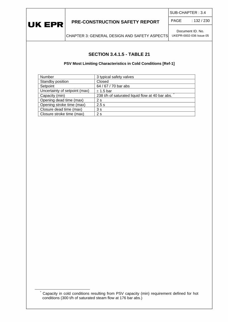
PRE-CONSTRUCTION SAFETY REPORT
CHAPTER 3: GENERAL DESIGN AND SAFETY ASPECTS
SUB-CHAPTER : 3.4
PAGE : 132 / 230
Document ID. No. UKEPR-0002-036 Issue 05
SECTION 3.4.1.5 - TABLE 21
PSV Most Limiting Characteristics in Cold Conditions [Ref-1] Number 3 typical safety valves Standby position Closed Setpoint 64 / 67 / 70 bar abs Uncertainty of setpoint (max) ± 1.5 bar Capacity (min) 238 t/h of saturated liquid flow at 40 bar abs. * Opening dead time (max) 2 s Opening stroke time (max) 2.5 s Closure dead time (max) 3 s Closure stroke time (max) 2 s
* Capacity in cold conditions resulting from PSV capacity (min) requirement defined for hot
conditions (300 t/h of saturated steam flow at 176 bar abs.)

PRE-CONSTRUCTION SAFETY REPORT
CHAPTER 3: GENERAL DESIGN AND SAFETY ASPECTS
SUB-CHAPTER : 3.4
PAGE : 133 / 230
Document ID. No. UKEPR-0002-036 Issue 05
SECTION 3.4.1.5 - TABLE 22
RCP [RCS] Overpressure Protection in Cold Conditions: Category 2 MHSI Spurious Actuation with all Large Miniflow Lines Opened
Most Limiting Assumptions [Ref-1]
PLANT INITIAL CONDITIONS - TYPICAL
− Equilibrium between primary side and secondary side − RCP [RCS] average temperature 120°C − Pressuriser pressure 30 bar abs − Pressuriser level 24.4 m3 nominal in cold conditions + 5% − All RRA [RHRS] trains isolated

PRE-CONSTRUCTION SAFETY REPORT
CHAPTER 3: GENERAL DESIGN AND SAFETY ASPECTS
SUB-CHAPTER : 3.4
PAGE : 134 / 230
Document ID. No. UKEPR-0002-036 Issue 05
SECTION 3.4.1.5 - TABLE 23
RCP [RCS] Overpressure Protection in Cold Conditions: Category 3 MHSI Spurious Actuation with one Large Miniflow Line Closed
Most Limiting Typical Assumptions [Ref-1]
PLANT INITIAL CONDITIONS - TYPICAL
− Equilibrium between primary side and secondary side − RCP [RCS] average temperature 30°C − Pressuriser pressure 19 bar abs − Pressuriser level 24.4 m3 nominal in cold conditions + 5% − All trains RRA [RHRS] isolated

PRE-CONSTRUCTION SAFETY REPORT
CHAPTER 3: GENERAL DESIGN AND SAFETY ASPECTS
SUB-CHAPTER : 3.4
PAGE : 135 / 230
Document ID. No. UKEPR-0002-036 Issue 05
SECTION 3.4.1.5 - TABLE 24
RCP [RCS] Overpressure in Cold Conditions: Category 2 MHSI Spurious Actuation with all Large Miniflow Lines Opened
Sequence of Events [Ref-1] Time (s)
Events
0.0 Initial conditions Spurious actuation of all MHSI pumps, large miniflow lines opened 800.0 Pressure peak at the most loaded point of the RCP [RCS] (40 bar abs at RCP outlet) Pressure peak in the pressuriser (35 bar abs) No opening of PSVs

PRE-CONSTRUCTION SAFETY REPORT
CHAPTER 3: GENERAL DESIGN AND SAFETY ASPECTS
SUB-CHAPTER : 3.4
PAGE : 136 / 230
Document ID. No. UKEPR-0002-036 Issue 05
SECTION 3.4.1.5 - TABLE 25
RCP [RCS] Overpressure in Cold Conditions: Category 3 MHSI Spurious Actuation with one Large Miniflow Line Closed
Typical Sequence of Events [Ref-1] Time (s)
Events
0.0 Initial conditions Spurious actuation of all MHSI pumps, one large miniflow line closed 525.0 Opening of PSV 800.0 Pressure peak at the most loaded point of the RCP [RCS] (77.0 bar abs at RCP outlet) Pressure peak in the pressuriser (73 bar abs)

PRE-CONSTRUCTION SAFETY REPORT
CHAPTER 3: GENERAL DESIGN AND SAFETY ASPECTS
SUB-CHAPTER : 3.4
PAGE : 137 / 230
Document ID. No. UKEPR-0002-036 Issue 05
SECTION 3.4.1.5 - FIGURE 1
RCP [RCS] Overpressure Protection: Category 2
Short-Term Loss of Offsite Power at Full Power [Ref-1]

PRE-CONSTRUCTION SAFETY REPORT
CHAPTER 3: GENERAL DESIGN AND SAFETY ASPECTS
SUB-CHAPTER : 3.4
PAGE : 138 / 230
Document ID. No. UKEPR-0002-036 Issue 05
SECTION 3.4.1.5 - FIGURE 2
RCP [RCS] Overpressure Protection: Category 3 Inadvertent Closure of all VIV [MSIV] at Full Power with three PSVs Operable
(No Failures) [Ref-1]

PRE-CONSTRUCTION SAFETY REPORT
CHAPTER 3: GENERAL DESIGN AND SAFETY ASPECTS
SUB-CHAPTER : 3.4
PAGE : 139 / 230
Document ID. No. UKEPR-0002-036 Issue 05
SECTION 3.4.1.5 - FIGURE 3
RCP [RCS] Overpressure Protection: Category 3 Inadvertent Closure of all VIV [MSIV] at Full Power with two PSVs Operable
(Failure of First PSV) [Ref-1]

PRE-CONSTRUCTION SAFETY REPORT
CHAPTER 3: GENERAL DESIGN AND SAFETY ASPECTS
SUB-CHAPTER : 3.4
PAGE : 140 / 230
Document ID. No. UKEPR-0002-036 Issue 05
SECTION 3.4.1.5 - FIGURE 4
RCP [RCS] Overpressure Protection: Category 4 Excessive Increase of Secondary Side Steam Flow at Full Power,
without Reactor Trip (ATWS, Stuck Rods) [Ref-1]

PRE-CONSTRUCTION SAFETY REPORT
CHAPTER 3: GENERAL DESIGN AND SAFETY ASPECTS
SUB-CHAPTER : 3.4
PAGE : 141 / 230
Document ID. No. UKEPR-0002-036 Issue 05
SECTION 3.4.1.5 - FIGURE 5
SG Overpressure Protection: Category 2 Turbine Trip at 60% Full Power [Ref-1]

PRE-CONSTRUCTION SAFETY REPORT
CHAPTER 3: GENERAL DESIGN AND SAFETY ASPECTS
SUB-CHAPTER : 3.4
PAGE : 142 / 230
Document ID. No. UKEPR-0002-036 Issue 05
SECTION 3.4.1.5 - FIGURE 6
SG Overpressure Protection: Category 3 Inadvertent Closure of all VIV [MSIV] at Full Power with two MSSVs Operable
(No Failures) [Ref-1]

PRE-CONSTRUCTION SAFETY REPORT
CHAPTER 3: GENERAL DESIGN AND SAFETY ASPECTS
SUB-CHAPTER : 3.4
PAGE : 143 / 230
Document ID. No. UKEPR-0002-036 Issue 05
SECTION 3.4.1.5 - FIGURE 7
SG Overpressure Protection: Category 3 Inadvertent Closure of all VIV [MSIV] at Full Power with one MSSV Operable
(Failure of one MSSV) [Ref-1]

PRE-CONSTRUCTION SAFETY REPORT
CHAPTER 3: GENERAL DESIGN AND SAFETY ASPECTS
SUB-CHAPTER : 3.4
PAGE : 144 / 230
Document ID. No. UKEPR-0002-036 Issue 05
SECTION 3.4.1.5 - FIGURE 8
SG Overpressure Protection: Category 4 Inadvertent Closure of all VIVs [MSIVs] at Full Power Without Reactor Trip
(ATWS, Stuck Rods) [Ref-1]

PRE-CONSTRUCTION SAFETY REPORT
CHAPTER 3: GENERAL DESIGN AND SAFETY ASPECTS
SUB-CHAPTER : 3.4
PAGE : 145 / 230
Document ID. No. UKEPR-0002-036 Issue 05
SECTION 3.4.1.5 - FIGURE 9
RCP [RCS] Overpressure in Cold Conditions: Category 2 MHSI Spurious Actuation with all Large Miniflow Lines Opened [Ref-1]

PRE-CONSTRUCTION SAFETY REPORT
CHAPTER 3: GENERAL DESIGN AND SAFETY ASPECTS
SUB-CHAPTER : 3.4
PAGE : 146 / 230
Document ID. No. UKEPR-0002-036 Issue 05
SECTION 3.4.1.5 - FIGURE 10
RCP [RCS] Overpressure in Cold Conditions: Category 3 MHSI Spurious Actuation with One Large Miniflow Line Closed [Ref-1]
PRE-CONSTRUCTION SAFETY REPORT
CHAPTER 3 : GENERAL DESIGN AND SAFETY ASPECTS
SUB-CHAPTER :3.4
PAGE : 147 / 230
Document ID.No. UKEPR-0002-036 Issue 05
1.6. FAST FRACTURE RISK
1.6.1. Introduction
This section presents specific fast fracture analysis of the UK EPR High Integrity Components to demonstrate avoidance of fracture caused by propagation of pre-existing crack-like defects submitted to a high level of stress and more particularly to Pressurised Thermal Shock [Ref-1].
The demonstration of integrity applied to the UK EPR design to avoid failure by fast fracture is based on a number of claims amongst the specific measures listed in section 0.3.6 of this sub-chapter, as well as specific UK requirements as follows:
• Absence of crack-like defects at the end of the manufacturing process - in particular defects of structural concern, i.e. which could lead to failure.
The UK specific requirements to ensure the absence of crack-like defects at the end of manufacturing are the following:
o a demonstration that there is a margin between the defect that can be detected (and thus rejected) with high reliability and the critical defect size which leads to failure. The target is to seek a margin of 2 (called the Defect Size Margin or DSM).
o the use of suitable redundant and diverse inspections during manufacturing, completed by the use of qualified inspection(s) to detect postulated defects of structural concern with high reliability (whose size must be equal or greater than the detectable defect). This implies the rigorous application of qualified examinations in terms of procedures, operator and equipment which comply with the recommendations of the European Network of Inspection and Qualification (ENIQ) framework.
• High material toughness which offers a good resistance to propagation of a crack-like defect.
The UK specific requirement to ensure the high toughness level is the realisation of fracture toughness measurements (with Compact Tension specimens) on forgings and welds.
• Absence of in-service crack propagation that could turn a pre-existing defect which is initially sub-critical into a critical defect.
The UK specific requirement to ensure the absence of in-service crack propagation is the demonstration that the margin established in the first claim hereabove is maintained despite the addition of end of life fatigue crack growth to the detectable defect.
In order to ensure these requirements a specific demonstration of integrity against the risk of fast fracture for High Integrity Components has been developed for the UK EPR based on a three-legged approach, which complements the overall safety demonstration presented in section 0.6 of this sub-chapter:

PRE-CONSTRUCTION SAFETY REPORT
CHAPTER 3 : GENERAL DESIGN AND SAFETY ASPECTS
SUB-CHAPTER :3.4
PAGE : 148 / 230
Document ID.No. UKEPR-0002-036 Issue 05
1. Use of fracture mechanics to determine the critical defect size at the end of life and demonstration that the Defect Size Margin between this critical defect size and the detectable defect grown by fatigue crack propagation by the end of life is larger than 2 as far as practicable.
The critical defect size is calculated for any main welds of HIC with the worst case defect in terms of location, shape and stresses including residual stresses, in any operating condition (normal and upset operating conditions (categories A and B), emergency operating conditions (category C) and faulted conditions (category D).
The fatigue crack growth has not been considered in the basic design since areas sensitive to fast fracture are generally not sensitive to fatigue,
2. Use of suitable redundant and diverse inspections during manufacturing, supplemented by the use of qualified inspection(s) on the main welds at the end of manufacturing.
3. Verification of the lower bound fracture toughness values used to determine the critical defect size by measurements on forgings and welds.
This demonstration focuses on the main welds of the HIC, where defects of structural concern are more likely to occur than in the base metal for the following reasons:
• by nature, the process of forging creates less defects in the base metal than the process of welding creates in weld joints,
• if a defect occurs, its nature and orientation is well known so that the NDT applied during the forging process will necessary detect it and allow it to be removed,
• the base metal has a higher fracture toughness value than the weld metal; this guarantees that the initiation or the propagation of a hypothetical defect will be reduced compared to the weld case,
• due to the forging process the base metal is free from residual stress, unlike a weld joint,
• even if a defect occurs, since it is oriented parallel to the wall its potential to grow in service is very low.
Nonetheless, fast fracture mechanics analyses will be performed in sensitive regions of the main forgings in the detailed design stage, to check whether these are limiting.
1.6.2. Fracture Mechanics Analysis and Defect Size Margin
As presented in section 1.6.1, the first leg of the integrity demonstration against fast fracture for High Integrity Components relies on a ratio larger than 2 as far as practicable between:
• the critical defect size (also called End of Life Limiting Defect Size or ELLDS), calculated by comparing the Stress Intensity Factor of a pre-existing defect and the fracture toughness of the material (with no margin), and
• the defect size which is detectable with high reliability (also called Qualified Examination Defect Size or QEDS) increased by fatigue crack propagation over the lifetime (also called Life Fatigue Crack Growth or LFCG).

PRE-CONSTRUCTION SAFETY REPORT
CHAPTER 3 : GENERAL DESIGN AND SAFETY ASPECTS
SUB-CHAPTER :3.4
PAGE : 149 / 230
Document ID.No. UKEPR-0002-036 Issue 05
In the basic design, considering a detectable defect size of 10 mm (to be demonstrated in section 1.6.3 below) and considering that Life Fatigue Crack Growth is not significant for the areas sensitive to fast fracture, the objective is to reach an ELLDS of 20 mm for ferritic components and austenitic piping (thick components) in order to attain the margin of 2. The demonstration of the margin of 2 for ferritic piping (thin components), Reactor Coolant Pump casing large repairs welds and flywheel is treated individually.
Objective
The defect to be considered in order to determine the ELLDS is generally a semi-elliptical surface defect defined by a depth over total length ratio (a/2c) equal to 1/6; this defect is positioned in the middle of the welded joint and oriented along the weld axis. It is postulated at the most loaded position: on the inner skin in most cases (in particular for areas submitted to cold thermal shock) and/or on the outer surface for few exceptions.
Type of defects
The critical defect is submitted to the worst case loads in terms of transients and mechanical loads among all the transients listed in section 1.1 and all loads listed in section 1.2. For most of the defects it corresponds to the most severe cold thermal shock.
Transients and loads
Residual stress loads also need to be taken into account. As residual stresses are due to imposed strains, the approach is to consider them as an equivalent temperature gradient constant through the cracked section. A bounding residual stress profile then contributes to the elastic Jel
th (via KI formulae) and the complementary thermal loading in kth then kth* parameters.
Stress Intensity Factor
The methodology [Ref-1] used to calculate the Stress Intensity Factor is performed using the formulae in Appendix 5.4 of RSE-M code [Ref-2], which enables more accurate calculations of Stress Intensity Factors and easier implementation of residual stresses than the design code RCC-M [Ref-3]. Three different methods can be used depending on the complexity of the weld geometry:
(J or K parameter)
• the first method is the use of the complete analytical solutions codified in the RSE-M code, which is completed by the specific fracture mechanics appendix of the R6 rules when needed (e.g. residual stress value). This methodology can be used for simple component geometries where analytical determination of elastic stresses can be performed.
• the second method is a mix of elastic Finite Element (FE) analyses (elastic FE analysis of the non-cracked structure to determine primary and secondary stresses) and analytical plastic corrections; it can be used for more complex cases where purely analytical solutions cannot be applied.
• For very complex areas not covered by the code formulae, or in order to improve the precision of the calculation, a more sophisticated methodology using elastic-plastic FE calculations on cracked models and/or welding simulations is applied.

PRE-CONSTRUCTION SAFETY REPORT
CHAPTER 3 : GENERAL DESIGN AND SAFETY ASPECTS
SUB-CHAPTER :3.4
PAGE : 150 / 230
Document ID.No. UKEPR-0002-036 Issue 05
In the analytical J or mixed FE-analytical evaluation scheme, the J approach as described in Appendix 5.4 of the RSE-M is applied. The principle of the approach is to calculate an elastic J (noted Jel) with KI formulae which then corrects Jel with a reference stress based correction. This KI is determined by stresses resulting from formulae applied to simple configurations (purely analytical scheme) or stresses determined by FE models without crack (intermediate approach for complex cases).
The criterion for
Criteria
brittle fracture
The criterion for
applies to ferritic components. It is an initiation criterion defined by the KIC(T) curve given as a function of the temperature of the studied point (surface or deepest point), at the time considered in the transient and for the end of life brittle to ductile transition temperature RTNDT (considering all types of ageing).
ductile tearing
( ) ( )TJT,aJ 2.0≤
applies to austenitic materials and to ferritic materials. For level A and B loadings, the criterion to be used is an initiation criterion:
where J0.2(T) is the specified toughness for the studied area at the temperature T of the transient.
For level C and D loadings, the first criterion used for assessment is the same initiation criterion. If it cannot be verified, a tearing stability criterion is used for assessment. A simplified demonstration of the defect stability is obtained showing that:
( ) ( )TJT,mm3aJ mm3a=∆≤+
where J(a+3mm, T) is J calculated for a defect 3 mm deeper than the initial defect (respecting the a/2c ratio equal to 1/6) and J∆a=3mm(T) is the J corresponding to a 3 mm propagation on the J-∆a curve at temperature T.
The evidence that any HIC weld has a limiting defect size larger than 20 mm for ferritic components and austenitic piping is given in PCSR Sub-chapter 5. For the Reactor Coolant Pump casing and flywheel and ferritic piping (main steam line, MSL) the demonstration of the margin of 2 is presented in Sub-chapter 5.4, section 1 and Chapter 10.
1.6.3. Non Destructive Testing
The second leg of the integrity against fast fracture demonstration for High Integrity Components relies on:
• the use of redundant and diverse inspections during manufacturing,
• a final verification performed at the end of manufacturing using qualified inspection(s) on the main welds; this inspection will be able to detect conceivable likely and unlikely defects of structural concern with high reliability and highly unlikely defects with reasonable capability where it is practicable to do so. The qualification applies to examinations, personnel and equipment.

PRE-CONSTRUCTION SAFETY REPORT
CHAPTER 3 : GENERAL DESIGN AND SAFETY ASPECTS
SUB-CHAPTER :3.4
PAGE : 151 / 230
Document ID.No. UKEPR-0002-036 Issue 05
This specific qualification has to be made with a margin of 2 as far as practicable between the critical defect size which leads to failure (ELLDS evaluated in section 1.6.2) and the size of the defect for which detection can be ensured with high reliability at the end of manufacturing increased by fatigue crack propagation over the lifetime.
The arguments and evidence that suitable NDT have been selected during, and at the end of, manufacturing are presented in Sub-chapters 5.3, 5.4 and 10.3.
Choice of NDT
The non-qualified examinations performed during the manufacturing process, although not strictly necessary to guarantee that the component is free of defects of structural concern, are:
• redundant and diverse examinations, which are able to detect different types of defects at different stages of the manufacturing process,
• performed as soon as possible in order to avoid a manufacturing deviation and the discovery of important defects in the final stages where it is more difficult to repair.
These examinations are either required by the code RCC-M or are additional requirements of the customer or the manufacturer for the component manufacturing process before the last qualified inspection to determine whether certain types of defect are present (e.g. detection of surface defects at different stages of the process using penetrant testing or magnetic particle testing, or detection of under clad cracking by ultrasonic examination, …).
These non-qualified examinations on HIC components will be generally supported by capability statements, which state the capability of the technique selected with respect to the chosen target.
The process to qualify inspection and operator [Ref-1] is described in Section 3.4.1.6 – Figure 1. It follows ENIQ recommendations. The qualification involves the independent action of a Qualification Body, commissioned by the Licensee.
Qualification process
The procedure qualification process is made up of four steps:
• Elicitation process:
The purpose of the elicitation process is to determine all potential defects that could occur in a weld and to associate a probability of occurrence that such defects could be of structural concern. Four levels of probability have been defined: conceivable likely, conceivable but unlikely, conceivable but highly unlikely and inconceivable.
• Inspection specification:
The purpose of the inspection specification is to define the target for NDT qualification.
Taking into consideration the material and geometry of the component, the inspection specification firstly defines the type of NDT to be used (volumetric or non-volumetric) and secondly the performance to be attained for the proposed NDT; the likely and unlikely defects will be detected with high reliability whereas the detectability of highly unlikely defects will be studied throughout the process although full detectability is not required under all circumstances.

PRE-CONSTRUCTION SAFETY REPORT
CHAPTER 3 : GENERAL DESIGN AND SAFETY ASPECTS
SUB-CHAPTER :3.4
PAGE : 152 / 230
Document ID.No. UKEPR-0002-036 Issue 05
• Qualification proposal:
The objective of the qualification proposal is to show how the manufacturer will demonstrate that the chosen inspection will meet the requirements of the inspection specification. In particular, the proposal will describe the test blocks, test defects and trials that are foreseen.
In response to this proposal, the Qualification Body issues a Qualification Procedure which gives a preliminary validation of the rationale presented in the qualification proposal and defines the process which will be followed by the Qualification Body in terms of surveillance of the qualification.
• Technical justification:
The technical justification is the most important part of the qualification file: it presents in detail the arguments and evidence which demonstrate that the chosen inspection(s) meet the requirements of the inspection specification. The content of the technical justification is based upon the ENIQ recommended proposal and is adapted to the NDT manufacturing qualification. It includes:
o physical reasoning and logical argument,
o use of modelling software,
o experimental results,
o test block and trials.
The technical justification also presents the arguments and evidence to support the level of operator qualification that has been proposed in the qualification proposal.
The operator qualification process [Ref-1] relies on three qualification levels depending on the degree of difficulty to implement the NDT technique, in accordance with ENIQ requirements:
Personnel qualification
• The qualification Level A may be applied when the parameters of the qualified NDT examination corresponds to the current practice for certified (EN 473) NDT personnel.
• The qualification level B may be applied when one or some parameters of the qualified NDT examination do not correspond to the current practice for certified (EN 473) NDT personnel.
• The qualification level C may be applied when the qualified NDT examination does not correspond to the current practice for certified (EN 473) NDT personnel. In this case, the qualified technique is generally a specific technique with for example probes and methodologies which are not part of current practice for EN 473 certification exams or current practice of manufacturing NDT.

PRE-CONSTRUCTION SAFETY REPORT
CHAPTER 3 : GENERAL DESIGN AND SAFETY ASPECTS
SUB-CHAPTER :3.4
PAGE : 153 / 230
Document ID.No. UKEPR-0002-036 Issue 05
1.6.4. Fracture Toughness
The third leg of the integrity against fast fracture demonstration for High Integrity Components relies on the demonstration that the fracture toughness values used to determine the limiting defect size are lower bound values and are actually met by the HIC.
This demonstration is made by measurements of the toughness on forgings and weld materials with Compact Tensile specimens, in addition to the acceptance tests required by the RCC-M code.
The evaluation of fracture toughness is based on two test approaches:
• performing fracture toughness tests on specific forgings for any project,
• performing fracture toughness tests on mock-ups manufactured with the same process as the actual project specific parts (recent EPR mock-ups results are reused where necessary).
The details of approach used for any HIC are described in Chapters 5 and 10.

PRE-CONSTRUCTION SAFETY REPORT
CHAPTER 3 : GENERAL DESIGN AND SAFETY ASPECTS
SUB-CHAPTER :3.4
PAGE : 154 / 230
Document ID.No. UKEPR-0002-036 Issue 05
SECTION 3.4.1.6 – FIGURE 1
Qualification process

PRE-CONSTRUCTION SAFETY REPORT
CHAPTER 3: GENERAL DESIGN AND SAFETY ASPECTS
SUB-CHAPTER : 3.4
PAGE : 155 / 230
Document ID.No. UKEPR-0002-036 Issue 05
2. TESTS AND DYNAMIC ANALYSES
2.1. ANALYSIS OF VIBRATION EFFECTS
Vibration testing is required for the main primary and secondary lines. Amongst other things, it provides evidence that the pipework will not be subject to stress damage caused by vibration, and will therefore avoid situations where vibration could threaten the integrity of pipework covered by the break preclusion principle.
2.1.1. Analysis of vibration effects on reactor coolant loops and pressuriser surge line
A thorough evaluation of piping vibration and dynamic effects of the reactor coolant loop/support system and the pressuriser surge line is carried out on the basis of a modal analysis of the reactor coolant loop behaviour in line with the extensive operating experience gained with 900 and 1300 MWe nuclear plants. The result is a test program consisting of visual observations to be conducted during start-up functional testing of the plant.
The purpose of these tests is to confirm that the system has been adequately designed and supported in order to prevent vibration as required by section B 3622.5 of the RCC-M. The tests include reactor coolant pump starts and trips. Particular attention is paid to those locations where the vibrations are expected to be the largest (i.e. the middle of a run).
It should be noted that the layout, size, etc., of the reactor coolant loop and surge line piping to be used in EPR units are similar to those of the plants now in operation in France. The operating experience that has been obtained from these plants indicates that the reactor coolant loop and surge line piping are adequately designed and supported to minimise vibration.
In addition, vibration levels of the reactor coolant pumps, which are the only mechanical components that could cause vibration of the reactor coolant loop and surge line piping, are measured and monitored as indicated in section 1 of Sub-chapter 5.4.
Tests are usually performed during hot functional tests to check that the RCP [RCS] can expand freely and that gaps between bumpers and equipment are acceptable.
2.1.2. Analysis of vibration effects on secondary piping
The precautionary measures taken to reduce the vibratory loadings in the main piping systems, such as a correct arrangement of the system and equipment and a correct set of piping supports, are verified by the control of their vibratory responses during tests performed under startup or initial service conditions. The purpose of these tests is to confirm that these piping systems, components, and supports have been designed adequately to withstand the flow-induced dynamic loadings under operational transients and steady-state conditions anticipated during service. The program includes a list of different flow modes, a list of selected locations for visual inspection and measurements, the acceptance criteria, and the possible corrective actions if any excessive vibration occurs. The general methodology is based on the ASME OM3 standard; the usual measurements are maximum velocities (or root mean square values) at mid span of continuous piping lines or at the ends of cantilever piping sections.

PRE-CONSTRUCTION SAFETY REPORT
CHAPTER 3: GENERAL DESIGN AND SAFETY ASPECTS
SUB-CHAPTER : 3.4
PAGE : 156 / 230
Document ID.No. UKEPR-0002-036 Issue 05
2.2. SEISMIC QUALIFICATION
The operability of Seismic Category I mechanical equipment must be demonstrated if the equipment is determined to be active, i.e., mechanical operation is required to perform a safety function.
The operability of active Class 2 and 3 pumps, active Class 1, 2, or 3 valves, and their respective drives, operators and essential auxiliary equipment within NSSS scope will be demonstrated by satisfying the criteria given in section 3 of this sub-chapter. Other active mechanical equipment will be shown operable either by tests, analyses or a combination of tests and analyses. Testing procedures similar to those outlined in Sub-chapter 3.7 for electrical equipment will be used to demonstrate operability if the component is mechanically or structurally complex such that its response cannot be adequately predicted analytically. Analysis may be used if the equipment can be modelled and analysed dynamically.
Inactive Seismic Category I equipment will be shown to have structural integrity during all plant conditions in one of the following ways:
• by an analysis satisfying the stress criteria applicable to the particular piece of equipment, or
• by a test showing that the equipment retains its structural integrity under the simulated test environment.
2.3. DYNAMIC RESPONSE OF REACTOR VESSEL INTERNALS UNDER OPERATIONAL FLOW EXCITATION
The excitation of the Reactor Pressure Vessel (RPV) internals structures by coolant flow is mainly random due to the flow turbulence in the downcomer annulus between the vessel and the core barrel. The flow turbulence generates mainly low frequency excitation because the spectral density of the pressure fluctuations decreases rapidly with frequency.
This is the reason why the vibratory behaviour of the RPV internals is located mainly in the low frequency range (0 to 30 Hz). The beam modes of the core barrel are typically around 8 Hz. Other components of the internals have higher response frequencies. All the displacement and strain levels are usually low.
The EPR RPV internals are similar to those of the 4-loop plants existing today in France or in Germany. However the EPR RPV internals include some modifications that may influence the flow-induced vibrations. These modifications are:
• Increase of the flow area in the downcomer between vessel and core barrel.
• Modification of the number and shape of the lower radial supports.
• Installation of a flow distribution device (removal of the bottom-mounted instrumentation structure implemented on the French 4-loops plant; in-core instrumentation is top-mounted on the EPR).
• Increase of the number of fuel assemblies.
• Replacement of the baffle assembly by the heavy reflector.

PRE-CONSTRUCTION SAFETY REPORT
CHAPTER 3: GENERAL DESIGN AND SAFETY ASPECTS
SUB-CHAPTER : 3.4
PAGE : 157 / 230
Document ID.No. UKEPR-0002-036 Issue 05
• Modification of the design and number of the control rod guide assemblies.
• Modification of the thermocouple guide tubes.
Some of these modifications are already implemented in the Siemens Konvoi plants, with a very good operating experience.
a) HYDRAVIB tests performed on the mechanical mock-up of the reactor lower internals.
The purpose is to provide data in order to:
• Make an assessment of the design of the RPV internals with respect to the flow-induced vibrations induced by the flow turbulence in the downcomer and in the RPV bottom head, and identify potential other flow-induced vibration phenomena like vortex shedding (discrete frequency).
• Make a good estimation of the internals vibratory behaviour that will be obtained by the instrumentation installed in the ‘first of a kind’ reactor internals during preoperational flow testing.
• Adjust the finite elements model of the internals.
Results of this test are currently being processed.
b) The MAGALY test performed on a mechanical mock-up of the Control Rod Guide Assembly (CRGA) with the Rod Cluster Control Assembly (RCCA) installed in the test loop [Ref-1].
The purpose of the test is to establish the natural frequencies and mode shape of the Control Rod Guide Assembly in water as well as the vibratory response of this component under flow in the EPR environment. These data will be used to analyse the vibration of the Control Rod Guide Assembly in the Upper Internals during normal plant operation.
From control rod vibrations and RCCA overall drag forces point of view, results demonstrate that the EPR CRGA design is fully satisfactory:
• RCCA overall drag forces satisfy requirements;
• control rods exhibit low amplitudes of vibration at all levels where measurements have been performed; they do not exceed amplitudes of vibrations of control rods in case of “1300 type” CRGA, which is considered as a maximal value not to exceed regarding wear phenomena.
2.4. PRE-OPERATIONAL FLOW-INDUCED VIBRATION TESTING OF REACTOR VESSEL INTERNALS
a) A pre-operational flow-induced vibration test of RPV internals will be performed on each new set of internals. This is the standard practice for the RPV internals. The test is done before core loading, at normal operating temperature and with the four Reactor Coolant Pumps in operation. During the test, the internals will be subjected to greater than normal flows because of the absence of the fuel. The test will last at least 240 hours. This provides a cyclic loading of approximately 107 cycles on the main structural elements of the internals. In addition there will be some operation with only one, two or three pumps running.

PRE-CONSTRUCTION SAFETY REPORT
CHAPTER 3: GENERAL DESIGN AND SAFETY ASPECTS
SUB-CHAPTER : 3.4
PAGE : 158 / 230
Document ID.No. UKEPR-0002-036 Issue 05
b) Before and after the hot functional test, a very extensive examination of the RPV internals will be done. This examination will put a special emphasis on the following areas:
• all major load-bearing elements of the reactor vessel internals relied upon to retain the core structure in place,
• the lateral, vertical and twisting restraints provided within the vessel,
• those locking and bolting devices whose failure could adversely affect the structural integrity of the internals,
• the inside of the RPV will also be inspected before and after the hot functional test, with all the internals removed. It will be confirmed that no loose parts or foreign material are in evidence.
The inspection will be done with magnifying glasses or other appropriate means. Acceptance standards are the same as those required in the factory workshop by the original design drawings and specifications. If no signs of abnormal wear or harmful vibrations are detected and no apparent structural changes take place, the reactor vessel internals are considered to be structurally adequate and sound for operation.
c) In addition to the pre- and post- hot functional test inspections, instrumentation may be installed on some key components of the first set of EPR RPV internals during its hot functional test. The instrumentation is removed before the first core loading. The purpose is to gain assurance that the vibration behaviour of the EPR RPV internals in normal operation is the same as the behaviour given by the mock-up tests results and the finite element analysis. The test results are compared with the expected values. The content of the instrumentation program is defined after completion of the tests on mock-ups indicated in section 2.3 in this sub-chapter and the related analyses.
2.5. DYNAMIC SYSTEM ANALYSIS OF THE RPV INTERNALS UNDER FAULTED CONDITIONS
The hydraulic loads on components inside the reactor vessel after a design basis Loss Of Coolant Accident (LOCA) in the hot or cold leg are described in section 1.3 in this sub-chapter.
2.6. CORRELATION OF RPV INTERNALS VIBRATION TESTS WITH ANALYTICAL RESULTS
The purpose is to compare the expected RPV internals flow-induced vibrations established by analytical methods or by mock-up tests with the actual in-plant behaviour of the first set of RPV internals. The scope of comparison is determined after the detailed definition of the instrumentation program implemented during the hot functional test.

PRE-CONSTRUCTION SAFETY REPORT
CHAPTER 3: GENERAL DESIGN AND SAFETY ASPECTS
SUB-CHAPTER : 3.4
PAGE : 159 / 230
Document ID.No. UKEPR-0002-036 Issue 05
3. REFERENCE SYSTEM FOR THE DESIGN OF M1, M2 OR M3 SAFETY CLASSIFIED MECHANICAL EQUIPMENT
As mentioned in Sub-chapter 3.2 of this PCSR (Classification principles), EPR mechanical equipment can be designed and manufactured in accordance with the requirements of codes other than the RCC-M code (except for M1 safety classified equipment, i.e. the RCP [RCS] and CSP [SSPB]). This section aims to specify general design rules applicable to the EPR with regard to mechanical equipment. In particular, the RCC-M version used to design and manufacture mechanical equipment for which the RCC-M code has been chosen is specified below.
3.1. VERSION OF THE RCC-M USED
When the RCC-M is applied to mechanical equipment of the EPR nuclear island, the applicable version is the RCC-M code Edition 2007 [Ref-1].
Additional requirements to those defined above may be prescribed in the equipment specifications in order to complete or clarify the requirements of the design code (in particular for new material), or to remove options.
The RCC-M applies to safety-classified equipment according to the rules explained in the sub-chapter on equipment classification (see Sub-chapter 3.2). The limits of the allowable stresses of the RCC-M are in particular chosen so as to guarantee the integrity of safety classified pressure vessels.
The component supports are designed in accordance with Volume H of the RCC-M when this code is chosen for supports. Reactor Vessel Internals, including the core support elements, are designed in accordance with Volume G of the RCC-M.
3.2. LOAD COMBINATIONS, TRANSIENTS AND STRESS LIMITS
3.2.1. Level 1 components of the RCC-M (M1 mechanical class)
The components in the RCP [RCS] and the CSP [SSPB] to which the Level 1 RCC-M requirements apply (M1 components1
These components must be designed in accordance with Volume B of the RCC-M. For M1 components, the very strict requirements of the level 1 RCC-M apply.
) are listed in the sub-chapter on equipment classification (see Sub-chapter 3.2).
The general design rules applicable to the sizing of pressurised components and to the analysis of their behaviour when subjected to the loads stipulated in the component specifications, are provided in the RCC-M B 3100.
1 Some RCC-M requirements may not be adapted to a given equipment ( in case of material not covered in the
RCC-M for example). In such cases, a dedicated technical specification is issued with equivalent quality requirements as those of RCC-M level 1

PRE-CONSTRUCTION SAFETY REPORT
CHAPTER 3: GENERAL DESIGN AND SAFETY ASPECTS
SUB-CHAPTER : 3.4
PAGE : 160 / 230
Document ID.No. UKEPR-0002-036 Issue 05
These rules aim to ensure compliance with the specified safety margins in relation to the types of damage which may occur following the loads imposed:
• excessive deformation and plastic instability,
• elastic or elasto-plastic instability,
• progressive deformation caused by repeated loads,
• fatigue (progressive),
• fast fracture.
During its operation, a component may be subjected to a certain number of different operating situations which are classified according to four categories (see section 1.1 of this sub-chapter), to which are added a conventional design condition and test situations. This classification is made according to the frequency of the event.
Equipment is subjected to representative environmental conditions (pressures, forces, thermal flux, irradiation, corrosion). Some of these actions (or loads) may produce mechanical stresses, as a function of the distortion of the equipment. The combination of these loads is called loading.
It is necessary to prevent damage to components subjected to these loads. For this purpose a series of stress criteria levels are defined. They correspond to:
• the probability of the loading (a frequent event must not induce undue fatigue; rare events can generate more constraining loads),
• the functional requirements of the equipment (integrity, operability, etc).
The rules regarding loadings and the levels of criteria to be met are presented in section 1.2 of this sub-chapter 3.4.
3.2.2. M2 and M3 safety classified components
Components with M2 and M3 levels of design and manufacturing quality are listed in the sub-chapter dealing with equipment classification (see Sub-chapter 3.2).
The mechanical design of M2 components is either compliant with the requirements of Volumes C (Level 2) of the RCC-M, or with those of another equivalent nuclear code (ASME section III-NC or, for a limited number of components, KTA).
The mechanical design of M3 components complies with the requirements of the harmonised European standards or of other codes consistent with the European Pressure Equipment Directive EC/97/23 (PED).
The design pressure, temperature and other loading conditions, which provide the bases for the design of M2 and M3 components of fluid systems, are presented in the sections describing these systems.
For M2 and M3 components, for which the RCC-M has been chosen as the design reference system, the requirements of levels 2 or 3 of the RCC-M are less strict than those of level 1. The associated stress limits are however sufficiently low to ensure that the equipment will perform its safety function (integrity, functional capacity, etc).

PRE-CONSTRUCTION SAFETY REPORT
CHAPTER 3: GENERAL DESIGN AND SAFETY ASPECTS
SUB-CHAPTER : 3.4
PAGE : 161 / 230
Document ID.No. UKEPR-0002-036 Issue 05
3.3. OPERABILITY UNDER SEISM OF M2 OR M3 SAFETY CLASSIFIED PUMPS AND VALVES
3.3.1. Pumps
Safety classified pumps are subjected to factory tests which include hydrostatic tests (see, for example the requirements of Volume C 5000 or D 5000 of the RCC-M when applicable), and to performance tests in order to determine the total dynamic head, the net positive suction head (NPSH), and other pump motor characteristics. When applicable, the temperature and the vibrations of the bearings are checked during performance testing.
In addition to the required tests, the pumps must be designed and supplied in accordance with the following criteria relating to seismic loading:
• If the lowest natural frequency is greater than 50 Hz, the pump and its support must be considered as basically rigid. A static analysis of the deformation of the rotor shaft is conducted, and the deformation is compared to allowable clearances for the rotor.
• If the natural frequency is found to be below 50 Hz, an analysis is conducted to determine the amplified input accelerations necessary to perform the static analysis.
• The maximum seismic loads on the nozzles are also taken into account in an analysis of the pump supports, to ensure that an unacceptable system misalignment cannot occur.
• In order to complete the seismic qualification procedures, the pump motor and all equipment essential for pump operation are qualified independently, to operate during the design earthquake, in accordance with the requirements of the RCC-E (see Sub-chapter 3.8).
3.3.2. Valves
Safety classified valves are subject to factory tests which include hydrostatic tests (see, for example, the requirements of volumes C 5000 or D 5000 of the RCC-M, when applicable), seat leakage testing and other functional tests.
The valves are designed using either stress analysis or standard design rules for minimum wall thickness requirements according to the nuclear codes, the harmonised European standards or to other codes satisfying the European Pressure Equipment Directive EC/97/23 (PED)
In addition, all valves and their extended structures are designed to have a first natural frequency greater than 50 Hz. An analysis is performed in applying three-dimensional static seismic loads at the centre of gravity of the extended structure. For design under seismic loading, the static load used is 4 g in all directions. These loads are applied simultaneously.
If the natural frequency is lower than 50 Hz, a dynamic calculation is made using real accelerations. A static calculation is acceptable if a factor of 1.5 is applied to the real accelerations.
Operational qualification of motors and electrical accessories is demonstrated by compliance to the requirements of the RCC-E or of another equivalent code, complemented by project data.

PRE-CONSTRUCTION SAFETY REPORT
CHAPTER 3: GENERAL DESIGN AND SAFETY ASPECTS
SUB-CHAPTER : 3.4
PAGE : 162 / 230
Document ID.No. UKEPR-0002-036 Issue 05
3.4. COMPONENT SUPPORTS
Supports welded to pressurised components are made of steel elements including plates, beams, flanges, snubbers, etc. In particular for piping, these supports may be standardised supports, when this is possible.
The design transients and load combinations applied to the supports are the same as those applied for the supported components.
The criteria applicable to supports are based on the principle that fluid system supports are as important as the system being supported.
They are divided into three sub-levels:
• supports for M1 components: the requirements of the RCC-M are applied (Volume H, requirements for S1 classified supports),
• supports for M2 components: the requirements of Volume H of the RCC-M are applied (supports classified S2) or the equivalent requirements of a nuclear code (ASME section III or KTA)
• supports for M3 components: the requirements of harmonised European standards are applicable or equivalent industrial practices compliant with the PED (if it is decided to use the RCC-M, the support is classified S2).
The supports of large RCC-M valve motors and large RCC-M pump motors are classified as the supports of the corresponding RCC-M components.
The supports of other electrical equipment (cables, connections, electrical cabinet, etc.) are dealt with in the RCC-E.
The internal equipment of fuel pools is classified as M2 component supports.
The design rules for supports or support components which are embedded in concrete are dealt with in the ETC-C (see Sub-chapter 3.8).
PRE-CONSTRUCTION SAFETY REPORT
CHAPTER 3: GENERAL DESIGN AND SAFETY ASPECTS
SUB-CHAPTER : 3.4
PAGE : 163 / 230
Document ID.No. UKEPR-0002-036 Issue 05
4. CONTROL ROD DRIVE MECHANISM [REF-1] TO [REF-4]
The Control Rod Drive Mechanism (RGL [CRDM]) carries out the following main functions:
• Reactivity control by inserting, blocking or withdrawing the Rod Control Cluster Assemblies (RCCA) over the height of the core,
• Automatic partial or reactor trip, by dropping the RCCA into the core,
• Maintenance of reactor coolant inventory and containment of radioactive substances by contributing to the integrity of the Reactor Coolant Pressure Boundary (by means of the pressure housing of the RGL [CRDM]),
• Measurement of rod position.
4.0. SAFETY REQUIREMENTS
4.0.1. Safety functions
The RGL [CRDM] contributes to the three main safety functions control of reactivity, heat removal and radioactive material containment either from a mitigatory point of view or from the normal operation of this component.
4.0.2. Functional criteria
4.0.2.1. Reactivity control
The control rod drive mechanism is involved in reactivity control through the dropping of the RCCAs into the core. RCCA drop is necessary to shutdown and maintain core subcriticality to reach a controlled state in PCC-2, PCC-3 and PCC-4, and a final state in RRC-A and RRC-B.
In addition, the position indicators for the drive rod signals show whether the control rod is out of alignment and indicate the extent to which each group of rod cluster control assemblies is inserted in the core.
RGL [CRDM] functions which participate in reactivity control during normal power operation are the control of RCP [RCS] average temperature and the management of rod configuration.
4.0.2.2. Heat removal
Heat removal from the reactor relies on the leaktightness of the RGL [CRDM] pressure housing. As part of the CPP [RCPB] (connected to the RGL [CRDM] adaptor at the top of the Reactor Pressure Vessel Closure Head (RPVCH)), the pressure housing prevents depletion of the reactor coolant system water inventory required for core cooling in all situations during plant operation.
PRE-CONSTRUCTION SAFETY REPORT
CHAPTER 3: GENERAL DESIGN AND SAFETY ASPECTS
SUB-CHAPTER : 3.4
PAGE : 164 / 230
Document ID.No. UKEPR-0002-036 Issue 05
4.0.2.3. Containment of radioactive substances
The RCCA drop also enables the integrity of the fuel cladding to be maintained by preventing pellet clad interaction and preventing unacceptable core power distributions (linear power density and axial offset) during PCC events.
RGL [CRDM] functions which participate in the containment of radioactive substances are the control of the core power distributions (linear power density and axial offset) and the leaktightness of the integrity of the pressure housing in all situations during plant operation (as part of the Reactor Coolant Pressure Boundary).
4.0.3. Design requirements
Design requirements are presented in a dedicated section (see Sub-chapter 3.2).
4.0.4. Testing
Once each control rod drive mechanism is installed on the reactor pressure vessel closure head, its operation is checked. These checks include measuring the rod drop time.
The drive rods are visually inspected when reloading the fuel.
To demonstrate that drive rods which are not activated by the Reactor Control Surveillance and Limitation system (RCSL) are in a state of readiness, their movability is partially verified while the reactor is functioning.
4.0.5. Qualification
The mechanical components necessary for the operation of the systems performing a safety function must be qualified. The qualification process must be appropriately specified for each type of component. Qualification principles and requirements are presented in a dedicated section (see Sub-chapter 3.6).
4.1. GENERAL
The role of the control rod drive mechanisms is to insert or withdraw all the control rods over a height equal to that of the core, and maintain them in any selected intermediate position. The position of a control rod in the core is tracked using digital and analogue position indicators. Another key function of the control rod drive mechanism is to free the control rod immediately after the current in the coils is interrupted (reactor trip).
The entire control rod drive mechanism comprises:
• A pressure housing with a flanged connection
• The entire latch unit
• The drive rod
• The coil housing
• The displacement limiter.

PRE-CONSTRUCTION SAFETY REPORT
CHAPTER 3: GENERAL DESIGN AND SAFETY ASPECTS
SUB-CHAPTER : 3.4
PAGE : 165 / 230
Document ID.No. UKEPR-0002-036 Issue 05
Each control rod drive mechanism works as an autonomous unit and may be mounted or removed independently of the others.
4.2. DESCRIPTION [REF-1]
4.2.1. Description of the mechanical design and supports
See drawing of the mechanism, Section 3.4.4 - Figure 1.
4.2.1.1. Pressure boundary and flanged connection
Each pressure housing comprises a lower section (mechanism housing) and an upper section (housing for the drive rod). It forms a thimble-like extension to the reactor pressure vessel and is attached to an adapter flange on the reactor pressure vessel closure head.
The mechanism casing contains the latch unit. The drive rod housing protects the drive rod as it moves upward when retracted from the core.
The pressure boundary comprises a set of five cylindrical parts welded together.
A support system connects the head equipment of the RGLs [CRDMs] with the wall of the reactor cavity in order to restrict any movement caused by vibration or external stress.
The flanged connection is equipped with two separate conical gaskets, each designed to withstand the operating pressure. Because of their conical form, the gaskets increase in outer diameter and decrease in inner diameter when the pressure housing is fastened. In this process, the edges of the conical gaskets find support into the corner radii of the flange and of the pressure housing which are then sealed hermetically as the result of local material plasticisation in the conical gaskets.
Due to the two separate gaskets, the flanged connection can be tightness tested as early as at the erection stage. The test line for this purpose is sealed off by means of a special valve after completion of tightness testing.
4.2.1.2. Latch unit
The latch unit is located in the lower part of the pressure housing. This is the actual drive which converts the magnetic forces generated by the coils outside the pressure housing into sequences of motion. In essence, it consists in three armatures which alternatively engage two groups of latches into the grooves of the drive rod, thus holding the RCCA in position or moving it up or down.
4.2.1.3. Drive rod
The drive rod is the device connecting the latch unit to the RCCA. It consists in a hollow rod which is grooved transversely in the upper section, over the required rod travel length.

PRE-CONSTRUCTION SAFETY REPORT
CHAPTER 3: GENERAL DESIGN AND SAFETY ASPECTS
SUB-CHAPTER : 3.4
PAGE : 166 / 230
Document ID.No. UKEPR-0002-036 Issue 05
4.2.1.4. Coil housing
The operating coil system consists of a lifting coil, a movable gripper coil and a stationary gripper coil. It is combined with the position indicator coils and included in a steel sheet casing to form a single assembly which can be easily pulled off the pressure housing. The steel sheet casing is arranged around the position indicator coils so that a chimney effect generates natural convection. Mounted on the top end of this assembly is a plug connector for the DC power supply to the operating coils and a second plug connector for transmitting the signals from the position indicator coils.
4.2.1.5. Displacement limiter
The displacement limiter is needed to restrict deflections of the upper part of the RGL [CRDM] during an earthquake.
4.2.2. Description of the electrical design
4.2.2.1. Polarity of the magnetic circuits
The lifting armature is common to the lifting and movable gripper coil magnetic circuits so that reciprocal magnetic interference occurs between them. Best behaviour of the RGL [CRDM] is obtained if the polarity of the lifting coil is opposed to that of the movable gripper coil.
4.2.2.2. Automatic reactor shutdown
When the reactor trip signal is given, all drive coils are de-energised, the latches are retracted from the rod grooves, the RCCA drops into the reactor core under gravity forces.
4.2.3. Functional description
The sequence presented below describes the lifting of a RCCA by one step starting from the rest position in which only the movable gripper coil is energised. The sequence is controlled by a timing sequencer which interrupts the power supply to the actuating coils in a specific sequence as follows.
Coil activation sequence Gripper movement Movable gripper coil is energised Rest position: drive rod supported by the
moveable gripper (gripping latches). Lifting coil energised The lifting electromagnet raises the drive rod
one step using the gripping latches. - Stationary gripper coil energised The holding latches engage with the drive-
rod fluting then rise to take the weight of the control rod.
Movable gripper coil de-energised The moveable gripper disengages the gripping latches from the drive rod fluting.
Lifting coil de-energised The moveable gripper drops to return to its initial position.
Movable gripper coil energised The gripping latches engage with the lower fluting.

PRE-CONSTRUCTION SAFETY REPORT
CHAPTER 3: GENERAL DESIGN AND SAFETY ASPECTS
SUB-CHAPTER : 3.4
PAGE : 167 / 230
Document ID.No. UKEPR-0002-036 Issue 05
Coil activation sequence Gripper movement - Stationary gripper coil de- energised
The stationary gripper descends, thus transferring the load to the moveable gripper, then withdraws the holding latches from the drive rod fluting.
Movable gripper coil energised Rest position: drive rod on the moveable gripper.
to Control rod raised by one step.
The cycle is repeated as many times as necessary to achieve the required displacement (number of steps). The control rod is inserted into the core by reversing the sequence.
In case of an interruption in the power supply to the coils, the armatures drop down, retracting the latches and the drive rod with RCCA falls into the core due to gravity. Towards the end of the travel path, the RCCA is decelerated by means of a hydraulic dashpot. As the control rod cluster stops, the spring inside the rod head compresses, and hence dissipates the residual energy.
4.2.4. Position indication
It is essential to have a device enabling the position of the rod, and thus of the cluster, to be determined at all times. To enable this, a system is provided consisting of a digital and analogue part. Limit positions can also be detected by the analogue part.
During operation the counted digital position is used by the reactor control and surveillance system. The protection system uses only the analogue position.
4.2.4.1. Counting of digital position
Counter status of the digital position can be checked by means of a display in the control room. At the bottom limit position, the position number 0 is displayed. Conversely, step number 416, which corresponds to the total number of steps, is indicated at the top limit position. During RCCA movement, adjustment of this information is performed by means of pulses counted by the reactor control and surveillance system equivalent to the number of ‘insert’ and ‘withdraw’ lifting coil commands. The limit position (number 0) is automatically displayed on rod drop.
The analogue rod position measurement gives independent information, to check the correct control rod movement. The analogue rod position information is on the other hand the only information suitable to be used by the reactor protection system.
4.2.4.2. Measurement of analogue position
The pressure housing extends above the operating coils with a reduced diameter in the form of an austenitic tube which serves as a guide for the withdrawn drive rod. This leads to the possibility of placing two coils (primary and secondary windings) over the upper pressure housing in order to implement an analogue measurement. Primary winding energising is performed by means of an imposed excitation current. When the martensitic drive rod is inserted, the secondary voltage rises and can be used for RCCA position measurement. In electrical terms, these position indicator coils constitute a transformer with a variable iron core.
The induced AC voltage signal is conditioned in an electronic module. The rod position is provided in "cm RCCA withdrawn steps" in the control room.

PRE-CONSTRUCTION SAFETY REPORT
CHAPTER 3: GENERAL DESIGN AND SAFETY ASPECTS
SUB-CHAPTER : 3.4
PAGE : 168 / 230
Document ID.No. UKEPR-0002-036 Issue 05
The analogue system for indicating the position is very reliable. Digital technology is used to compensate the signal for temperature variations along the rod. The uncertainty in the reading is approximately ± 3% (preliminary value).
Additional coils are installed to indicate the top and bottom limit positions in order to permit a more precise detection of limit positions. Evaluation of the voltage induced in the limit position coils is performed on an electronic module.
4.3. DESIGN BASIS
4.3.1. General
The mechanical design (static and dynamic) of the RGL [CRDM] satisfies the requirements imposed in view of:
• Proper functioning
• Withstanding load conditions
• Selection and use of proper materials
• Maintenance free operation.
With allowance being made for the interaction between these requirements.
The basic design parameters of the RGLs [CRDMs] are:
• In view of operability
o pressure and temperature
o length of a single step
o length of travel
o mass of drive rod and RCCA
o step frequency
o total rod drop time (maximum):
- 3.5 seconds without earthquake
- 5 seconds with earthquake
• In view of integrity and rod drop (pressure housing)
o pressure housing classification: RCC-M, EPR version, class 1
o pressure
o temperature

PRE-CONSTRUCTION SAFETY REPORT
CHAPTER 3: GENERAL DESIGN AND SAFETY ASPECTS
SUB-CHAPTER : 3.4
PAGE : 169 / 230
Document ID.No. UKEPR-0002-036 Issue 05
o vibrations, flow forces
o external hazards (e.g. seismic conditions).
The fail-safe principle is achieved by using gravity (without any active component) for the shut down function of the RGL [CRDM].
4.3.2. Pressure housing
The design of the pressure housing is equal to other EPRs, complies with Class 1 of the RCC-M and does not significantly depart from the design of the Konvoi, which was built to comply with the German technical rules and regulations.
The implementation of RCC-M level 1 is not possible in all cases (e.g. there is no available "STR" Material Procurement Specification in Section II of RCC-M 2007 for martensitic grade or stabilised austenitic grade used for CRDM procurement); dedicated specifications can therefore be used. The requirements applicable to M1 equipment can be implemented on case by case basis.
4.3.3. Functional requirements
This involves the speed for rod movements (normal drive speed):
• Required maximum speed: 75.0 cm/minute
• Required average minimum speed: 37.5 cm/minute.
The design is within the range of the required speeds.
The power produced by the lifting coil is much higher than needed for lifting the RCCA and drive rod (high reserve power).
The RGLs [CRDMs] are designed in such a way that the RCCAs are released in case of electrical power interruption.
4.4. MATERIALS
The materials used to manufacture the control rod drive mechanism comply with quality requirements in the following areas:
• Qualification (for instance, material manufacturer’s experience and references)
• Suitability for use (for instance, welding, hot or cold forming)
• Chemical composition (for instance, carbon content, alloy elements, associated or trace elements)
• Mechanical properties (for instance, toughness, tensile strength at ambient and operating temperatures, fatigue properties)
• Resistance to the corrosion mechanisms specific to the application envisaged

PRE-CONSTRUCTION SAFETY REPORT
CHAPTER 3: GENERAL DESIGN AND SAFETY ASPECTS
SUB-CHAPTER : 3.4
PAGE : 170 / 230
Document ID.No. UKEPR-0002-036 Issue 05
• Reduction of the radiation level in the Unit (for instance, Co level)
• Magnetic properties.
The materials used for the control rod drive mechanism comply with the German KTA Regulations. Additional studies have been performed to enable them for the inclusion in the RCC-M Construction Regulations, Section II, Materials.
4.5. PRELIMINARY TESTS
After assembly, each complete control rod drive mechanism (including the coils for the lifting assembly, the connectors and the coils for the position indicators) is functionally tested. During the test program, the drive mechanism moves the rods by stepping. The program also includes rod drop tests, in which the rod is simulated by a pendant weight.
Once the vessel head is in place, the operation of each control rod drive mechanism is checked again. These checks include control rod movement and drop time measuring with the RCCAs fitted.
4.6. EXPERIENCE IN OPERATION [REF-1] [REF-2]
Over 1,200 control rod drive mechanisms have already been in operation for extended periods of up to 35 years. No plant outage has been caused by the failure of a control rod drive mechanism, even though 40% of the plants have been in operation for over 20 years. Over the 35 years, the drives have undergone between 0.6 x 10+6 and 1.8 x 10+6 incremental movements.
4.6.1. Mechanical part
Several unscheduled descents of the control rod and irregular step functions have been observed. They have been resolved by replacing the springs or the entire latch units.
4.6.2. Electrical part
The coil connection insulation was changed from silicon to capton/glass filament insulation due to embrittlement.
4.7. IN-SERVICE INSPECTABILITY AND REPLACEABILITY
A series of tests can be performed during operation and/or outage in order to establish the condition of the RGLs [CRDMs]. This concerns principally electrical tests, such as coil voltage or current and drop time oscillograms which enable reliable verification of faultless mechanical sequence of movements in operation.
Visual examinations of drive rods during refuelling are also included. The internal condition of the RGL [CRDM] under examination can be assessed with the results thus obtained. Where there are signs of increased wear, prompt remedial action can be initiated; this can extend to a replacement of parts or even of complete assemblies.

PRE-CONSTRUCTION SAFETY REPORT
CHAPTER 3: GENERAL DESIGN AND SAFETY ASPECTS
SUB-CHAPTER : 3.4
PAGE : 171 / 230
Document ID.No. UKEPR-0002-036 Issue 05
Visual inspection of the drive rods is also scheduled for when the fuel is reloaded. The water tightness of the flanged connections may also be tested by depressurising from outside the closure-head insulation.
The pressure boundary is also tested during the periodic hydraulic testing of the primary cooling system.
The internal surface of the pressure boundary above the lifting mechanism may also be tested using eddy currents with no further dismantling.
The coils are easily interchangeable (if necessary) and replaceable. When they are dismantled, the outside and the welded joints of the pressure boundary may be inspected non-destructively.
In all circumstances, the entire mechanism and any of its parts may easily be replaced.
4.8. LIFE EXPECTANCY [REF-1] [REF-2]
The lifetime of the mechanical parts is limited by wear and fatigue in the moving parts. The main factor is the number of incremental movements carried out by the lifting mechanism.
The maximum number of incremental movements that the most active assembly is expected to perform during the lifetime of an EPR plant is set at 6 x 10⁶. During prototype testing it was shown that the CRDM could perform 9 x 10⁶ steps.
If the live operating conditions within an EPR plant lead to a situation where the most active control rod drive mechanism could exceed its demonstrated capacity, preventive measures would be taken at a proper time, for instance, swapping or replacing the control rod drive mechanism which is easily achievable because of the design with a flanged connection.
Other types of degradation of the mechanical parts are excluded by the design, or by the choice of operating conditions:
• Radiation embrittlement: based on the radiation levels assessed in the design, ageing and reduced toughness in the steels used for the control rod drive mechanisms are not considered to be significant.
• Thermal ageing: in operation, in steady state, the temperature of the material used for the pressure boundary is between 160°C and 250°C at the casing. There is no risk of thermal ageing under these conditions.
• Corrosion: the materials are the same as those used in plants currently in operation and are known to offer good corrosion resistance in the chemical conditions experienced in PWRs.
4.9. INTERFACES WITH THE CONTROL ROD DRIVE MECHANISM
The following equipment is involved:
• The adaptor connecting the vessel head and the control rod drive mechanism, its joints and the thermal sleeve
• Tightness testing system for the flanged connection

PRE-CONSTRUCTION SAFETY REPORT
CHAPTER 3: GENERAL DESIGN AND SAFETY ASPECTS
SUB-CHAPTER : 3.4
PAGE : 172 / 230
Document ID.No. UKEPR-0002-036 Issue 05
• Head equipment considering cable bridge, seismic supporting equipment, reactor cavity and connection panels
• Air cooling system (reactor compartment)
• Electrical and I&C equipment
• Coupling of drive rod with the RCCA
• RCCA guide
• Auxiliary bridge with latching tool for latching and unlatching of the drive rod to the RCCA
• Reactor building crane (decoupling of the drive rods)

PRE-CONSTRUCTION SAFETY REPORT
CHAPTER 3: GENERAL DESIGN AND SAFETY ASPECTS
SUB-CHAPTER : 3.4
PAGE : 173 / 230
Document ID.No. UKEPR-0002-036 Issue 05
SECTION 3.4.4 - FIGURE 1
Assembly Design of the Control Rod Drive Mechanism [Ref-1]

PRE-CONSTRUCTION SAFETY REPORT
CHAPTER 3: GENERAL DESIGN AND SAFETY ASPECTS
SUB-CHAPTER : 3.4 PAGE : 174 / 230
Document ID.No. UKEPR-0002-036 Issue 05
5. REACTOR PRESSURE VESSEL – UPPER CORE SUPPORT STRUCTURES
5.0. SAFETY REQUIREMENTS
5.0.1. Safety functions
The internal structures (upper and lower) of the reactor pressure vessel (RPV) contribute to the following safety functions:
• Control of reactivity by ensuring reactor shutdown and by enabling insertion of the in-core instrumentation,
• Core cooling by maintaining a geometry enabling core cooling whatever the operating conditions,
• Containment of radioactive materials by maintaining a vibration amplitude such that the leaktightness of the fuel assemblies is preserved,
• Integrity of the second barrier by limiting the flux of fast neutrons which may lead to embrittlement of the reactor vessel.
5.0.2. Functional criteria
5.0.2.1. Reactivity control
The internal structures of the reactor vessel should enable:
• Rod Cluster Control Assemblies (RCCAs) to enter the core to ensure reactor shutdown in all circumstances,
• in-core neutron flux measurement using the “aeroball” system and Self-Powered Neutron Detectors (SPND),
• measurement of temperatures at the core outlet and in the vessel upper dome by means of thermocouples
5.0.2.2. Decay heat removal
The free circulation of water through and between the fuel assemblies must be maintained under all circumstances.
5.0.2.3. Radioactive substance containment
The vibration amplitude of the internal reactor structures in normal operation must be sufficiently low to prevent any unacceptable stresses on the fuel assemblies.

PRE-CONSTRUCTION SAFETY REPORT
CHAPTER 3: GENERAL DESIGN AND SAFETY ASPECTS
SUB-CHAPTER : 3.4 PAGE : 175 / 230
Document ID.No. UKEPR-0002-036 Issue 05
5.0.2.4. Integrity of the second barrier
In addition to the functions described in section 5.0.1 of this sub-chapter, the internal structures of the reactor vessel are used in the monitoring program of the reactor vessel material. The irradiation specimen for this material is contained in capsules inserted into the baskets fixed outside the core barrel. These capsules may be extracted from the baskets (and new ones can be reinserted) thus enabling monitoring of vessel material.
5.0.3. Design requirements
5.0.3.1. Requirements from safety classification
5.0.3.1.1. Safety classification
The internal structures of the reactor vessel are classified according to the classification principles presented in the paragraph on the classification of equipment (see Sub-chapter 3.2).
5.0.3.1.2. Single failure criterion (active and passive)
Not applicable
5.0.3.1.3. Emergency-supplied power sources
Not applicable
5.0.3.1.4. Qualification in operating conditions
Not applicable
5.0.3.1.5. Mechanical, electrical and instrumentation and control classifications
As far as mechanical integrity is concerned, the internal structures of the reactor vessel are divided into two sub-classes:
• Core Support structures (CS) which are necessary for the mechanical integrity of the fuel assemblies,
• Internal Structures (IS).
Core support structures must be designed according to the RCC-M (see Sub-chapter 3.8) section G.
5.0.3.1.6. Seismic classification
The internal structures of the vessel are seismically classified according to the principles presented in the paragraph on the classification of equipment (see Sub-chapter 3.2).

PRE-CONSTRUCTION SAFETY REPORT
CHAPTER 3: GENERAL DESIGN AND SAFETY ASPECTS
SUB-CHAPTER : 3.4 PAGE : 176 / 230
Document ID.No. UKEPR-0002-036 Issue 05
5.0.3.2. Technical Guidelines
The general provisions of the Technical Guidelines apply to the internal structures of the vessel (see Sub-chapter 3.1).
5.0.3.3. Basic Safety Rules
See Sub-chapter 1.4.
5.0.3.4. Hazards
5.0.3.4.1. Internal hazards
Not applicable
5.0.3.4.2. External hazards
The internal structures of the reactor vessel are protected against external hazards, in accordance with the requirements of Sub-chapter 13.1.
5.0.4. Inspections
It is possible to completely remove the internal structures of the reactor vessel for:
• In-service inspection of the internal structures,
• Inspection of the inner walls of the reactor vessel.
5.1. GENERAL INFORMATION
The upper internal structures are located above the core, in the region of the vessel which contains the nozzles. They fulfil the following important functions:
• ensure the correct position and alignment of fuel assemblies,
• support the forces due to the fuel assemblies spring preload,
• distribute the coolant,
• ensure the correct position and alignment of rod cluster control assemblies (RCCAs),
• guide the level measurement probes,
• serve as a support for the core instrumentation,
• support the dynamic forces produced during PCC-4 events.
They constitute the upper part of the reactor core and house the RCCAs and the lances for the in-core and other instrumentation.
PRE-CONSTRUCTION SAFETY REPORT
CHAPTER 3: GENERAL DESIGN AND SAFETY ASPECTS
SUB-CHAPTER : 3.4
PAGE : 177 / 230
Document ID.No. UKEPR-0002-036 Issue 05
The upper internal structures are comprised of:
the Upper Support Plate (USP) with its wall and flange,
the Upper Core Plate (UCP),
89 Control Rod Guide Assemblies (CRGA),
89 CRGA columns,
12 normal columns,
4 columns for the Level Measurement Probes: LMP columns,
52 guide tubes for the instrumentation lance thimbles,
356 centring pins for the CRGA,
482 upper centring pins for fuel assemblies.
5.2. DESCRIPTION
Section 3.4.5 - Figures 1 to 7 illustrate the design of the upper internal structures [Ref-1] to [Ref-4].
5.2.1. Upper support assembly
The upper support assembly is illustrated in Section 3.4.5 - Figure 1.
The upper support assembly (in the form of an inverted top hat) separates the upper plenum from the RPV closure head. It is the major structural component of the upper internal structures. It is connected to the upper core plate by the CRGA support columns, the normal columns and the LMP columns.
The upper support assembly includes the upper support plate, a cylindrical skirt and a flange integrated to the skirt. b .The connection of the cylindrical skirt to the USP is carried out as a full penetration welding. The cross section of the USP contains 89 holes at the RCCA positions, 4 holes at the level measurement probe positions and 52 holes at the in-core instrumentation lance thimble positions.
The upper end of the holes at the RCCA locations is closed by a connection flange to the CRGA. The lower end is closed by a connection flange to the CRGA column.
For level measurement positions, the LMP column is connected by a flange to the lower face of the plate. The hole, which is much smaller than the one described above, is closed at the upper face of the plate by a LMP thimble upper housing comprised of a connection flange, a tube and a cone at its upper end to facilitate the insertion of the level measurement probes.
The alignment pins are used to position the RPV closure head, the vessel, and the lower and upper internal structures. They are comprised of two parts fixed respectively to the flange of the core barrel and the flange of the upper support.
{CCI removed}

PRE-CONSTRUCTION SAFETY REPORT
CHAPTER 3: GENERAL DESIGN AND SAFETY ASPECTS
SUB-CHAPTER : 3.4
PAGE : 178 / 230
Document ID.No. UKEPR-0002-036 Issue 05
The upper support assembly flange is also comprised of 4 quick-connection sockets (roto-lock) for handling the upper internals and of 32 holes for inserting the spray nozzles.
The hold-down spring is in between the upper internal structure flange and the core barrel flange.
5.2.2. Upper core plate (UCP)
The upper core plate is illustrated in Section 3.4.5 - Figure 1.
The UCP b, is made up of austenitic stainless steel.
This plate is connected to the upper support assembly by the CRGA columns, the normal columns and the LMP columns. These columns ensure the correct spacing between the upper core plate and the upper support assembly. The other parts on the upper core plate are the upper centring pins for the fuel assemblies and the centring pins for the CRGA.
The fuel assembly upper centring pins (2 per fuel assembly) and the CRGA pins ensure accurate positioning of the CRGAs in relation to the corresponding fuel assemblies.
Accurate alignment between the upper core plate and the heavy reflector (i.e. the core cavity) is obtained by means of four centring pins fixed to the heavy reflector and which insert into four sets of inserts fixed to the plate.
The upper core plate is equipped with 89 square holes for the CRGA, 136 unrestricted flow holes and 16 holes above which the lower flanges on the normal columns and LMP columns are located.
5.2.3. Support columns
The support columns are illustrated in Section 3.4.5 - Figures 1 and 2.
A distinction is made between the three types of support column:
CRGA columns,
normal columns,
LMP columns
The CRGA columns are located above those fuel assembly positions which are equipped with a RCCA (89 locations).
The CRGA skeletons are located inside these columns.
Each CRGA column is connected to its lower flange by gussets. These gussets pass through the lower open section between the CRGA column tube and the connection flange to the upper core plate. This system of gussets enables passage of the primary flow from the core outlet to the upper plenum.
The peripheral portion of the upper core plate at the core periphery is connected to the upper support assembly by the normal columns and the LMP columns.
{CCI removed}

PRE-CONSTRUCTION SAFETY REPORT
CHAPTER 3: GENERAL DESIGN AND SAFETY ASPECTS
SUB-CHAPTER : 3.4
PAGE : 179 / 230
Document ID.No. UKEPR-0002-036 Issue 05
5.2.4. CRGA [REF-1]
The CRGA is illustrated in Section 3.4.5 - Figure 2 [Ref-2].
The CRGA ensure correct alignment and drop characteristic of the RCCA into the core.
The CRGA are mainly comprised of 8 tie rods and 15 guide plates. The three lowest guide plates of the CRGA are additionally connected by 16 slotted guide tubes (C tubes), in which the individual RCCA rods slide freely.
The rod cluster control assemblies are protected from the flow by the CRGA columns.
The CRGA are screwed to the top of the upper support plate. The correct position in relation to the fuel assembly is obtained by centring the lower CRGA plate on the four centring pins fixed to the upper core plate.
The upper section of the CRGA is closed in the upper RPV dome. The cover plate at the top of the CRGA upper housing within the upper dome is equipped with a hole which, due to a predetermined gap between the plate and the drive rod, ensures a specific flow. The resulting pressure in the head is less than the pressure in the centre of the upper plenum and greater than the pressure around the upper plenum. In these conditions, the “hot” coolant flows from the upper plenum through the central CRGA columns into the dome where it is mixed with the “cold” by-pass flow from the annular space between the vessel and the core barrel via the spray nozzles. The mixed fluid then flows from the upper dome to the upper plenum through the surrounding CRGA columns.
When the drive rod is disconnected, the cover plate at the top of the CRGA maintains the drive rod almost in the vertical position. This facilitates insertion of the drive rod in the adapter when the vessel head is lowered onto the vessel.
5.2.5. Level measurement probe columns
The level measurement probe columns are illustrated in Section 3.4.5 - Figures 1 and 7.
The 4 columns for the Level Measurement Probes (LMP) are comprised mainly of two parts: the column itself and the thimble upper housing. The thimble upper housing is installed on the top of the upper support plate. This upper housing is comprised of a connection flange at its lower end which is inserted into a USP spot facing and is bolted via screws, a tube, and a conical guide to facilitate the insertion of the level measurement probes.
The column itself is a tube b
Its top is fixed by a flange under the upper support plate. Its lower end is fixed to the upper core plate. A special water inlet element attached to the bottom end of the tube enables a quiet water entrance.
5.2.6. Guide tube for core instrumentation
The guide tubes are illustrated in Section 3.4.5 - Figures 1 and 7.
The 52 guide tubes for in-core instrumentation are tubes b made of austenitic stainless steel. They are fixed by means of brackets to the CRGA guide columns.
{CCI removed}
{CCI removed}
PRE-CONSTRUCTION SAFETY REPORT
CHAPTER 3: GENERAL DESIGN AND SAFETY ASPECTS
SUB-CHAPTER : 3.4 PAGE : 180 / 230
Document ID.No. UKEPR-0002-036 Issue 05
The upper end of the guide tubes is inserted into a hole in the upper support plate. A gap is left for thermal expansion. The lower end is welded to a bracket which is bolted inside a flow hole of the UCP.
5.3. MECHANICAL DESIGN
5.3.1. Design requirements
The requirements are those of the RCC-M (see Sub-chapter 3.8).
5.3.2. Functional requirements
The service life of the RPV internals is 60 years.
Based on the loading conditions defined and according to the rules of RCC-M (see Sub-chapter 3.8), the mechanical design ensures the integrity of the core support structures for all operating conditions PCC-1 to PCC-4 and RRC-A.
The RPV internals are structurally designed for the permanent loads and the transients of normal and accident operation resulting from temperature transients, external accidents and a loss of coolant accident (LOCA). The design ensures the cooling capacity and the shutdown of the reactor in all circumstances [Ref-1] [Ref-2].
The design analysis takes account of the following loads for normal operating and accident conditions:
• mechanical loads due to weight, to permanent flow, to vibrations, and preload forces
• thermal load due to differential thermal expansion of the individual parts and to gamma induced heating
• the vibrations and impact forces caused by a loss of coolant accident and external events, taking into account local conditions as regards the extent and the frequency.
The resistance of the RPV internals to cyclic loads (fatigue resistance) is checked by calculating and measuring vibrations.
The RPV internals are divided into two sub-classes:
• CS for components functioning as core support,
• IS for the other components.
As regards upper internal structures, the CS components include for example the upper core plate, the upper support plate and the CRGA columns.
5.3.3. Materials
The following characteristics, concerning the quality of the materials defined for the manufacture of upper internal structures, are taken into account:
• qualification (for example: material manufacturer’s experience, his references)

PRE-CONSTRUCTION SAFETY REPORT
CHAPTER 3: GENERAL DESIGN AND SAFETY ASPECTS
SUB-CHAPTER : 3.4 PAGE : 181 / 230
Document ID.No. UKEPR-0002-036 Issue 05
• manufacturing process used (for example: welding, hot or cold forming)
• chemical compositions (for example: carbon content, alloy elements, associated and elements and traces of elements)
• mechanical properties during operating life (for example: mechanical resistance at ambient temperature and at higher temperatures, fatigue)
• resistance to corrosion mechanisms corresponding to the specific situation
• reduction of the irradiation level in the nuclear plant (for example Cobalt content)
MAIN COMPONENTS MATERIALS
Components Materials
Upper support plate
Upper core plate
CRGA support column
CRGA
Normal support column
Level measurement column
Guide tube for core instrumentation
Fuel assemblies centring pin
Z3 CN 18-10 + N2
Z2 CN 19-10 + N2
Z2 CN 19-10 + N2
Z2 CN 19-10 + N2
Z2 CN 19-10 + N2
Z2 CN 19-10 + N2
Z2 CN 19-10 + N2
Z2 CND 17-12 Cold worked
The materials used for the RPV upper internals are specified in the RCC-M (see Sub-chapter 3.8).
5.4. HYDRAULIC DESIGN
5.4.1. Hydraulic design of upper internal structures
The hydraulic resistance and the sections where the coolant flows between the region of the upper RPV dome and the upper plenum are important in ensuring the conditions of a warm closed upper dome.
There are different flow paths from the upper dome to the upper plenum:
• flow through the cover plates of the CRGA upper housings,

PRE-CONSTRUCTION SAFETY REPORT
CHAPTER 3: GENERAL DESIGN AND SAFETY ASPECTS
SUB-CHAPTER : 3.4 PAGE : 182 / 230
Document ID.No. UKEPR-0002-036 Issue 05
• flow through the guide tubes protecting the instrumentation lance thimbles for the aeroball system, the self-powered neutron detectors (SPND) and the thermocouples,
• flow through the thimble passage holes for the level measurement probes (LMP column).
In addition, the route from the core to the upper plenum is taken into account.
This is the flow through the upper core plate:
• at the CRGA positions,
• at the other positions (without CRGA),
• in the annular space between the core barrel and the upper core plate.
The geometry in the CRGAs with regard to the hydraulic resistances is characterised by plates which lead to large variations in flow areas like orifices.
The instrumentation guide tubes for the aeroball system, SPND and thermocouples are located in this region. The flow path geometries in the various types of guide tubes are identical.
The resistances in the CRGA, in the instrumentation lance conduits and in the upper core plate have been evaluated and taken into account in by-pass flow studies [Ref-1] [Ref-2].
5.4.2. Hydraulic design of the upper dome
The upper support plate, which separates the upper dome and the upper plenum, is not a leaktight barrier between the hot water exiting the core and the mixed water from the upper RPV dome. This is due to the fact that the RCCA must be able to be raised and lowered and therefore a gap with sufficient clearance is needed for the drive rod at the cover plate (top of the CRGA housing).
To control the core by-pass flow which cools the upper RPV head, there are 32 spray nozzles on the core barrel flange. These by-pass nozzles are uniformly distributed around a circumference whose average diameter is between the outer diameter of the hold-down spring and the contact zone of the upper internals flange with the vessel head.
The bypass of 0.5% of the total inlet flow rate of the RPV induces a dome pressure which is lower than the pressure in the centre of the upper plenum and higher than the pressure at the upper plenum periphery. In these conditions, the “hot” coolant flows from the upper plenum through the central CRGA columns into the dome where it is mixed with the “cold” by-pass flow. The fluid then flows back from the upper dome via the cover plates through the peripheral CRGA columns to the upper plenum [Ref-1].
The thermal-hydraulic design of the dome requires a certain minimum value for the downflow head loss coefficient in the CRGA in order to ensure the correct flow and thus temperature of the closure head.

PRE-CONSTRUCTION SAFETY REPORT
CHAPTER 3: GENERAL DESIGN AND SAFETY ASPECTS
SUB-CHAPTER : 3.4 PAGE : 183 / 230
Document ID.No. UKEPR-0002-036 Issue 05
5.5. SIZING CALCULATIONS
The basis for preliminary estimation of the ability to resist to applied loads is obtained by considering the forces applied to the support columns for various cases and from the results of experimental or analytical stress analyses. A three-dimensional analysis of fluid-structure interactions in a loss of coolant accident has been carried out [Ref-1]. The support columns can withstand a complete guillotine break of the surge line with a 1 ms opening time.
The dimensions of the upper internal structures are checked by means of an analysis of the main structures and comparison of the results with the applicable standards (RCC-M, see Sub-chapter 3.8). It has been shown that the upper internal structures meet the functional requirements [Ref-2].
5.6. ARRANGEMENT
The RPV upper internals arrangement is presented in the following figures: Section 3.4.5 - Figure 1, Section 3.4.5 - Figure 3 and Section 3.4.5 - Figure 7.
5.7. INSPECTABILITY AND REPAIRABILITY
In-service visual inspection of the upper internal structures is possible. The upper internal structures can be replaced as a whole or element by element. The design of the CRGA, the instrumentation and the upper fuel pins is such that replacement is possible.
5.8. OPERATING EXPERIENCE
The structural and hydraulic design of the upper internal structures is based on the principles and equipment already implemented in operating power plants. The CRGA and the CRGA columns are similar to those used in KONVOI plants (adapted to 17x17 fuel assemblies) and the support structure and closed dome arrangement are a French standard.
5.9. CORE INSTRUMENTATION
5.9.1. General information
The mechanical design of the core instrumentation meets the requirements imposed by:
• correct operation,
• load conditions,
• correct selection and use of materials,
• good manufacturing practices,
• ease of maintenance
and by taking account of the interaction between these requirements.

PRE-CONSTRUCTION SAFETY REPORT
CHAPTER 3: GENERAL DESIGN AND SAFETY ASPECTS
SUB-CHAPTER : 3.4 PAGE : 184 / 230
Document ID.No. UKEPR-0002-036 Issue 05
Core instrumentation is comprised of the following components:
• 12 instrumentation lances,
• 12 fingers for 72 neutron detectors (SPND) and 36 thermocouples (temperature measurement at the core outlet),
• 40 fingers with aeroball,
• 4 level measurement probes,
• 16 instrumentation penetrations in the vessel head, located above the core periphery,
• 4 temperature sensors for temperature measurements in the upper dome,
• 1 penetration close to the vessel head centre to measure the temperature in the upper RPV dome.
The design of these components is based on the experience acquired with the core instrumentation in German PWR plants. These proposals are presented below with the main dimensions.
All the instrumentation is inserted into the vessel via the RPV head. This is top-mounted instrumentation.
5.9.2. Description [Ref-1] to [Ref-8]
Core instrumentation is illustrated in Section 3.4.5 - Figure 7.
The mechanical design of the instrumentation lances is fundamentally the same as the instrumentation lances used in German power plants.
Instrumentation lances for the aeroball system, fixed neutron detectors in the core (SPND) and thermocouples
Each instrumentation lance includes a vertical lance shaft with a lance head, a yoke lying on the top face of the upper support plate and the fingers fixed to the yoke.
The lance head forms a watertight penetration into the vessel head for the aeroball system tubes, the SPND cables and the thermocouples. With the nozzle closure, the lance head constitutes the sealed joint for the instrumentation penetration.
The tubes and cables are routed through the lance shaft to the yoke on the upper support plate from where they continue horizontally to their respective finger.
The instrumentation fingers are fixed to the yoke and are guided from this position to the guide-tubes of the fuel assemblies. At the upper end of the fuel assembly, over a short distance, they are not guided. This is because the core outlet temperature is measured in this zone. The corresponding fingers contain holes in this zone to enable direct flow of the coolant to the thermocouples.
Inside the fuel assemblies, the fingers are inserted into guide-tubes normally used for the RCCAs.

PRE-CONSTRUCTION SAFETY REPORT
CHAPTER 3: GENERAL DESIGN AND SAFETY ASPECTS
SUB-CHAPTER : 3.4 PAGE : 185 / 230
Document ID.No. UKEPR-0002-036 Issue 05
The instrumentation lance fingers containing the SPND can be replaced individually.
During refuelling shutdown, all the plugs and threaded connections are removed and protected by a leaktight tube (cap). After removing the sealing joints from the instrumentation penetrations, the vessel head can be raised or lowered above the lances.
The lances themselves are removed from the upper support structure using a special tool (lance gripping tool). They are inserted using other special tools (guide loading funnel tool).
There are different types of instrumentation device:
• Vessel level measurement probes
A vessel level measurement probe is used to determine that a sufficient level of water is present in the upper plenum. This measurement, particularly useful in the event of a loss of coolant accident, aims to indicate potential uncovery of the core.
The vessel level measurement probes are located in the LMP columns around the upper plenum. A special device fixed to the lower end of the columns is used to supply the measurement system with low flow water conditions (KONVOI system). Holes for circulation of this water are machined in the upper section of the LMP column, under the upper support plate.
The LMP is comprised of the following elements:
o a penetration in the vessel head similar to that for the instrumentation lances. A centring cone of geometry specific to the vessel level measurement probes is fixed to the lower part of these penetrations in the vessel head
o 2 thermocouples in the upper part to measure the temperature in the upper dome (see below) for two of the four probes
o 3 sensors to measure the vessel level in the upper plenum
o a cone in the lower part of the sensor to ensure correct insertion into the guide tube screwed to the upper support plate
• Thermocouple probes
A thermocouple probe measures the temperature of the environment inside the upper head, the volume under the vessel head.
For the EPR, there are five thermocouples at three different levels above the level of the vessel/head flange. One of the five thermocouples is located near the RPV head centre in order to measure the temperature in the upper part of the RPV dome. The four other thermocouples are related to two of the 4 level measurement probes in the core periphery.
The probe is comprised of the following elements:
o a leaktight tube
o a thermocouple head
o a probe finger
o guide tubes inside the leaktight tube and the probe thimble

PRE-CONSTRUCTION SAFETY REPORT
CHAPTER 3: GENERAL DESIGN AND SAFETY ASPECTS
SUB-CHAPTER : 3.4
PAGE : 186 / 230
Document ID.No. UKEPR-0002-036 Issue 05
For the thermocouple located near the centre of the head, the penetration is a of vent tube type. The four other thermocouples, associated with two of the four vessel level measurement probes, use its penetration in the vessel. The thermocouple probe heads are used for sealed penetration into the vessel head for the thermocouples cables and are placed at the level of the cable run. This height makes maintenance easy. The thermocouples can be replaced individually.
The thermocouple cables run inside the vertical guide tubes from the probe head to the measurement point in the upper head. It is not necessary to bend the guide tubes.
The probe finger and the guide tubes contain holes at the elevation of the temperature measurements to enable direct flow towards the thermocouples.
The thermocouple arrangement is illustrated in Section 3.4.5 - Figure 7.
5.9.3. Arrangement of penetrations
16 instrumentation penetrations above the core periphery are necessary for the core instrumentation and the vessel level measurement probes.
An additional penetration near the centre of the vessel head is necessary for temperature measurement in the highest part of the upper head.
The instrumentation penetrations are sealed at the position of the lance heads and probe head by means of capping devices.
5.9.4. Functional requirements
Fuel assembly guide tubes
The guide-tubes used have been selected in accordance with the following three requirements:
b
o The aeroball system and SPND fingers must be distributed as uniformly as possible throughout the core, using the additional flexibility afforded by the fact that individual fuel assemblies may accommodate up to two fingers (one aeroball finger and one SPND finger)
o Reduced intervals for the guide tube brackets in the upper support structure
Thermocouples for temperature measurement at the core outlet
The number of measurement points results from the number of fingers with the SPND.
Three thermocouples are installed in each SPND finger (total number: 36).
The thermocouples are located at the upper end of the fuel assembly.
Thermocouples for temperature measurement in the upper head
One thermocouple shall be mounted near the centre of the upper head.
{CCI removed}

PRE-CONSTRUCTION SAFETY REPORT
CHAPTER 3: GENERAL DESIGN AND SAFETY ASPECTS
SUB-CHAPTER : 3.4 PAGE : 187 / 230
Document ID.No. UKEPR-0002-036 Issue 05
• Aeroball system
Maximum extrapolation distance from one aeroball probe = two fuel assembly pitches.
All the radial positions of the fuel assemblies where RCCAs are not inserted must be monitored by at least two probes.
The number of aeroballs required is based on the above requirements. The total number of probes should be a multiple of 4.
• Level measurement
In order to prevent the probes from being exposed to significant loads during a possible loss of coolant accident, the level measurement probes are placed in zones of low flow inside the vessel between the coolant outlet nozzles.
A total of 4 level measurement probes with three sensors each are installed. This leads to a total of 12 sensors.
• Core Self-Powered Neutron Detectors (SPND)
A total of 12 fingers with 6 SPNDs are installed. This yields a total of 72 SPNDs.
The fingers containing the neutron detectors are inserted into the fuel assembly guide tubes. The fuel assembly guide tubes selected to house the instrumentation lance fingers are illustrated in Section 3.4.5 - Figure 7.
Of the total of 6 SPNDs for each finger, three will be arranged in the upper region of the core and three in the lower region (maximum one inside the dashpot).
5.9.5. Design data and interfaces
• Design Data
o Design pressure and design temperature:
- of aeroball tube inside core (poutside): 176 bar 351°C
- of aeroball tube outside core (pinside): 25 bar 50°C
- of lance head: 176 bar 351°C
- of level measurement probe: 176 bar 351°C
- of thermocouple probe: 176 bar 351°C
o Test pressure and test temperature:
According to RCC-M requirements section B, see Sub-chapter 3.8
o Fluid:
- Primary flow except for aeroball system
- Aeroball system: Nitrogen

PRE-CONSTRUCTION SAFETY REPORT
CHAPTER 3: GENERAL DESIGN AND SAFETY ASPECTS
SUB-CHAPTER : 3.4
PAGE : 188 / 230
Document ID.No.UKEPR-0002-036 Issue 05
o Seismic design
Pressure boundary parts inside the reactor are designed according to Seismic Class I.
o Design life
The design life for the lance with tube (without detectors): 60 years
o Materials
- Instrumentations lances: Austenitic Stainless Steel
- Ball tubes and propelling gas tubes: Austenitic Stainless Steel
- Balls: Austenitic Vanadium Alloy
- Fingers: Austenitic Stainless Steel
- Ball stops: Austenitic Stainless Steel
- Valves: Austenitic Stainless Steel
- Screwed connector: Austenitic Stainless Steel
b
� Interfaces
The following elements are concerned:
o vessel head including penetrations
o vessel internal structures including CRGA
o fuel assemblies
o head equipment, i.e. the cable run and connection panels
o electrical equipment and control and instrumentation devices
o reactor control system
o nitrogen supply circuit
o fuel assembly cap assembly.
{CCI removed}

PRE-CONSTRUCTION SAFETY REPORT
CHAPTER 3: GENERAL DESIGN AND SAFETY ASPECTS
SUB-CHAPTER : 3.4 PAGE : 189 / 230
Document ID.No. UKEPR-0002-036 Issue 05
• Ease of repair and replacement
o In-service inspection
- Inspection can be carried out by verifying the measurement made during reactor operation.
• Maintenance and repair operations
The space required to insert the instrumentation lances inside the vessel is available in the fuel assembly guide tubes which are not occupied by the RCCA rods. The fingers are inserted in these guide tubes to prevent any damage during insertion and withdrawal.
The lance sits freely in the dead flow zone above the upper support plate. The fingers are guided by the tubes over their whole height. This ensures reliable insertion of the lances and, during reactor operation, protects the fingers against the flow forces of the coolant which may cause vibrations.
The aeroball tubes and the tubes carrying the motor gas are together on the yoke and exit from the lance head which is sealed with the penetration. Above the lance head a removable screwed joint is installed on the tubes. The tubes are protected from the water by a cap when the reactor cavity is full.
The method of replacing all the sensors in an instrumentation lance enables replacement within 2 hours. The time for removal of an instrumentation lance until the next one can be grabbed is 10 -15 minutes. The time required for insertion of a lance, from grabbing in the fuel pool until grabbing of the next one is 20 - 30 minutes.
Any instrumentation lance removed from the reactor because it contains faulty detectors can be replaced routinely during plant maintenance using the lance gripping tool and special tools. The defective fingers are temporarily stored in the reactor pool until final removal.
Vessel level measurement sensors can be rapidly replaced during a plant outage (for example due to a broken sensor) using a special grab. For this replacement, the sealing device to be opened is of identical design to that of the control rod drive mechanisms. As such, the special gripping tool used for replacement is the same. The replacement probes are temporarily stored in the cavity.
A defective upper head temperature measurement thermocouple can be replaced during a plant outage from the cable platform when the vessel head is on its storage stand.
• Reference technologies
The instrumentation lance was first installed in the Stade nuclear power plant in 1971. Since then, all other light water reactors built by KWU have been fitted with this instrumentation system. Due to conclusive operating experience, only small improvements have been made and the basic design has not been changed.
The systems have operated with an operational availability of 100% over the 260 years of accumulated operation in 16 power plants.
The vessel level measurement sensors, with their proven design, have been installed since 1983 in 15 Siemens PWRs, with excellent feedback.

PRE-CONSTRUCTION SAFETY REPORT
CHAPTER 3: GENERAL DESIGN AND SAFETY ASPECTS
SUB-CHAPTER : 3.4 PAGE : 190 / 230
Document ID.No. UKEPR-0002-036 Issue 05
The mechanical design of the thermocouple sensor is based on the design of the core instrumentation used without any problems in the KWU PWR plant since 1968.

PRE-CONSTRUCTION SAFETY REPORT
CHAPTER 3: GENERAL DESIGN AND SAFETY ASPECTS
SUB-CHAPTER : 3.4 PAGE : 191 / 230
Document ID.No. UKEPR-0002-036 Issue 05
SECTION 3.4.5 - FIGURE 1
Upper Internals Structure Assembly
Guide tube for core
instrumentation
Normal column Upper core plate CRGA column
LMP column
CRGA upper housing Cover plate Upper support
assembly Alignment pin
Roto-lock
CRGA

PRE-CONSTRUCTION SAFETY REPORT
CHAPTER 3: GENERAL DESIGN AND SAFETY ASPECTS
SUB-CHAPTER : 3.4 PAGE : 192 / 230
Document ID.No. UKEPR-0002-036 Issue 05
SECTION 3.4.5 - FIGURE 2
Control Rod Guide Assembly (CRGA)
Cover plate
Guide plate
Upper housing
Upper support
Tie rod
CRGA column
Upper core plate
Gusset
CRGA pin

PRE-CONSTRUCTION SAFETY REPORT
CHAPTER 3: GENERAL DESIGN AND SAFETY ASPECTS
SUB-CHAPTER : 3.4 PAGE : 193 / 230
Document ID.No. UKEPR-0002-036 Issue 05
SECTION 3.4.5 - FIGURE 3
Upper Core Plate - Top View

PRE-CONSTRUCTION SAFETY REPORT
CHAPTER 3: GENERAL DESIGN AND SAFETY ASPECTS
SUB-CHAPTER : 3.4 PAGE : 194 / 230
Document ID.No. UKEPR-0002-036 Issue 05
SECTION 3.4.5 - FIGURE 4
Upper Internals - Top View

PRE-CONSTRUCTION SAFETY REPORT
CHAPTER 3: GENERAL DESIGN AND SAFETY ASPECTS
SUB-CHAPTER : 3.4 PAGE : 195 / 230
Document ID.No. UKEPR-0002-036 Issue 05
SECTION 3.4.5 - FIGURE 5
Schematic of an Instrumentation Tube

PRE-CONSTRUCTION SAFETY REPORT
CHAPTER 3: GENERAL DESIGN AND SAFETY ASPECTS
SUB-CHAPTER : 3.4 PAGE : 196 / 230
Document ID.No. UKEPR-0002-036 Issue 05
SECTION 3.4.5 - FIGURE 6
Housing Plate and Interfaces with the Drive Rod
Cover plate
Drive rod (Φmaxi 53 mm)
Drive rod
Cover plate (top of CRGA upper
housing)
Φ 86 mm for the top guide plate
Φ 50 mm for the bottom guide plate
Φ 61 mm for the other guide plates
Guide plate
Φ 66 mm through hole in the cover
plate

PRE-CONSTRUCTION SAFETY REPORT
CHAPTER 3: GENERAL DESIGN AND SAFETY ASPECTS
SUB-CHAPTER : 3.4 PAGE : 197 / 230
Document ID.No. UKEPR-0002-036 Issue 05
SECTION 3.4.5 - FIGURE 7
Upper Internals Structure with the Instrumentation
Penetration for vessel level measurement
probe
Penetration for instrumentation lance
Penetration for drive rods
Vessel head
Core barrel
CRGA upper housing
CRGA column
LMP column
Upper support
plate
Penetration for dome thermocouple
Presence of two thermocouples on one
of the vessel level measurement probes
Instrumentation lance finger guide
tube
Yoke for instrumentation
lances
Vessel level measurement
sensors

PRE-CONSTRUCTION SAFETY REPORT
CHAPTER 3: GENERAL DESIGN AND SAFETY ASPECTS
SUB-CHAPTER : 3.4 PAGE : 198 / 230
Document ID.No. UKEPR-0002-036 Issue 05
6. REACTOR PRESSURE VESSEL – LOWER INTERNALS
6.0. SAFETY REQUIREMENTS
The safety requirements that apply to the lower internals of the vessel are given in the section dealing with the upper internal structures of the reactor vessel (see section 5 of this sub-chapter).
6.1. DESIGN PRINCIPLES
During plant operation, the whole structure of the reactor pressure vessel (RPV) internals (including the reactor instrumentation) usually operates as an assembly inside the RPV.
However, certain reactor operating conditions (for example: refuelling, in-service inspection, handling, etc.) require a distinction to be made between the two main internal structures:
• the upper internal structures which are always removed for refuelling,
• the lower internal structures, which are only removed for in-service inspection of the vessel.
The current section 6 of this sub-chapter deals only with the lower internals structure. The upper internal structures are addressed with in section 5 of this sub-chapter.
The lower internal structures comprise three main elements:
• the lower core support structure, which is the main load resistant structure of the lower internals,
• the heavy reflector, which is the lateral structure surrounding the core,
• the flow distribution device which controls the hydraulics in the lower plenum.
6.1.1. Functions of the RPV lower internals
The main functions of the lower internals are:
6.1.1.1. Core support and positioning function
• the lower internals support, locate, restrain, protect and guide the core components (fuel assemblies) in order to insure a homogeneous core cooling, with respect to neutronic and thermal-hydraulic needs;
• the lower internals limit the mechanical loadings from the core components;
• the lower internals allow core loading, unloading and reloading.

PRE-CONSTRUCTION SAFETY REPORT
CHAPTER 3: GENERAL DESIGN AND SAFETY ASPECTS
SUB-CHAPTER : 3.4 PAGE : 199 / 230
Document ID.No. UKEPR-0002-036 Issue 05
6.1.1.2. RPV coolant flow distribution function
The lower internals canalise the coolant:
• to achieve a homogeneous flow distribution in the core.
The flow entering the different fuel assemblies is as equal as possible, in order to:
o minimise the increase in the fuel assembly lifting forces induced by the flow being higher than the average mechanical flow per assembly;
o minimise the DNBR penalty induced by a flow being lower than the average thermal-hydraulic flow per assembly;
o minimise the transverse flow between adjacent assemblies in order to reduce the fuel rod vibration risk.
• to achieve a good mixing coefficient between loops:
o to favour good homogenisation of boron concentration;
o to limit the coolant temperature differences in reactor core during asymmetric transients.
• to ensure flow circulation to the RPV upper dome
• to enhance RCP [RCS] natural circulation in the case of loss of forced reactor coolant flow;
• to ensure effective cooling of the RPV internals and the vessel.
6.1.1.3. Relation with other equipment
The lower internals:
• provide RPV irradiation protection,
• support and protect the RPV irradiation surveillance capsules,
• support and adjust the position of the upper internals,
• provide a secondary core support in order to limit the consequences of a downward displacement of the core in the event of a postulated failure of the lower internals.
6.1.2. Description
The lower internals:
• are vertically supported by a ledge machined in the flange of the RPV,
• are tightly maintained vertically inside the RPV by an annular hold-down spring located between the flanges of the lower and of the upper internals, which prevents the lower internals from lifting off the RPV ledge;

PRE-CONSTRUCTION SAFETY REPORT
CHAPTER 3: GENERAL DESIGN AND SAFETY ASPECTS
SUB-CHAPTER : 3.4 PAGE : 200 / 230
Document ID.No. UKEPR-0002-036 Issue 05
• are tightly positioned in rotation in the RPV.
The arrangement allows easy insertion and removal of the whole structure.
6.1.2.1. Lower core support structure
The lower core support structure is the major supporting assembly of the total RPV internals structure [Ref-1] to [Ref-3].
The lower core support structure consists of the core barrel and its flange, the lower support plate, and the interface devices with the RPV and the upper internals.
The lower core support structure transmits the vertical loads to the vessel flange and distributes the horizontal loads between the vessel flange and the lower radial support system.
The components comprising the lower support structure are:
• an upper flange which is the core barrel flange. This is located inside the vessel flange and transmits the loads from the fuel assemblies and the lower internal structures to the vessel;
• a cylindrical barrel, which is the core barrel. This is welded to the core barrel flange and is made up of cylindrical sections welded together;
• the upper section of the barrel has four outlet nozzles in front of the four vessel outlet nozzles. These provide the passageway for the reactor coolant from the core to the RPV outlet nozzles. The maximum radial gap between the core barrel and RPV nozzles is controlled to restrict the amount of by-pass flow;
• the lower support plate is welded to the bottom of the core barrel. This thick forging supports all the fuel assemblies, the heavy reflector and the flow distribution device. It contains holes which direct and distribute the flow of reactor coolant to the inlet of the core. The lower radial support system locates the lower internal structures in the bottom of the vessel;
• the fuel assemblies making up the core are placed in the core cavity which is surrounded by the heavy reflector. They rest on the lower support plate which contains the lower fuel pins that provide location and alignment for the bottom nozzles of the fuel assemblies;
• The irradiation capsule baskets. These are fixed to the outside of the core barrel at locations where the neutron flux is greater than on the inside of the RPV core shells. They locate, support, restrain, protect and guide the irradiation capsules. They also participate in their cooling.
The interface devices consist of alignment pins and lower radial support system:
• the alignment between the head and the vessel is ensured by 8 half-pins, four of them are fixed to the core barrel flange and extend above and below the flange. The portion of the pins extending below the flange engages pockets in the reactor pressure vessel flange to provide alignment of the lower core support assembly to the reactor pressure vessel. The portion of the pins extending above the core barrel flange engages the half-pin fixed to the upper core support assembly flange. This latter half-pin extends into pockets provided in the reactor pressure vessel head;
PRE-CONSTRUCTION SAFETY REPORT
CHAPTER 3: GENERAL DESIGN AND SAFETY ASPECTS
SUB-CHAPTER : 3.4 PAGE : 201 / 230
Document ID.No. UKEPR-0002-036 Issue 05
• this arrangement ensures alignment of all these components. A minimum clearance is maintained between the pins and the engagement pockets to ensure functional alignment and to allow ease of assembly;
• the lower radial support system consists of 8 radial keys, which are welded on the wall of the reactor pressure vessel, which engage clevis inserts attached to the periphery of the lower support plate;
• This system restricts the lower end of the lower core support assembly from rotational and/or tangential movements, while allowing for radial and axial differential displacements between the RPV and the internals
6.1.2.2. Heavy reflector
The heavy reflector is located inside the core barrel, above the lower support plate [Ref-1].
The heavy reflector forms the radial periphery of the core. Through the dimensional control of the core cavity, i.e. the gap between the fuel assemblies and the reflector, it contributes to the required flow path control of the reactor coolant through the core and to the lateral restraint of the core.
The heat generated inside the steel structure by absorption of gamma radiation is removed by water flowing through holes and gaps.
To avoid the presence of a welded or bolted connection near the core, the reflector is made of stacked up forged slabs which are positioned together with keys and rings, and which are attached to the lower support plate by tie-rods.
6.1.2.3. Flow distribution device
The flow distribution device is fixed under the lower support plate by means of bolted vertical columns. It homogenises the flow distribution at the inlet of the lower support plate [Ref-1].
6.1.2.4. Miscellaneous
The hold-down spring is a circumferential spring which is located between the flanges of the upper and lower core support structures when these structures are assembled inside the reactor pressure vessel.
Hold-down spring
This spring is used to maintain a preload to limit the radial movements and to prevent axial movements of the upper and lower internals, during the reactor operation. The preload is provided only when the reactor pressure vessel head is clamped in place with the RPV closure studs and nuts.
A secondary core support is provided in the lower downcomer area between the bottom of the lower core plate and the reactor pressure vessel. This structure uses the eight keys of the lower radial support system.
Secondary core support
The functions of the secondary core support, after a hypothetical failure of the core barrel, are:

PRE-CONSTRUCTION SAFETY REPORT
CHAPTER 3: GENERAL DESIGN AND SAFETY ASPECTS
SUB-CHAPTER : 3.4 PAGE : 202 / 230
Document ID.No. UKEPR-0002-036 Issue 05
• To limit the vertical downward displacement of the lower internals assembly to prevent withdrawal of the control rod assemblies from the core and to maintain the downcomer annulus area for cool cooling.
• to transmit the vertical drop loads uniformly to the vessel.
This system comprises eight radial keys. Four of those keys, on the main axes of the vessel, provide tangential centring for the lower internal structures (small gap during normal operation) and serve as radial stops (quite large gap) during PCC-4 events. The four other keys only serve as radial stops. Inserts on the keys and on the internal structures are used to make the necessary gaps in the tangential, radial and vertical directions. Hard facing is used on those inserts which have small tangential gaps.
Lower radial system
6.2. OPERATING CONDITIONS
The lower internal structures are designed in accordance with the general specifications, i.e. the specified operating conditions, the requirements with regard to interfaces, design rules and criteria.
For each specific operating condition, there is a corresponding set of environmental parameters: pressure, forces, coolant temperatures, thermal flux, and neutron irradiation.
These parameters act (usually as a function of time) on the components without producing mechanical work.
With the mechanical and thermal loads, they define sets of loads which are used in the mechanical design.
6.2.1. Operating conditions
The service life is 60 years, based on a load factor of 90%.
The classification of the operating conditions into categories, the list of the corresponding conditions and their description are provided in the section on the design of mechanical components (see section 1 of this sub-chapter).
6.2.2. Loadings and load combinations
The design of the lower internals is based on the following loading types:
• Pressure differences due to coolant flow.
• Weight of structures.
• Additional loads such as those due to other structures, the reactor core, instrumentation and safety equipment (for example, fuel assembly weight, fuel assembly and core component spring force, hold-down spring preload, interface loads between the components, etc.).
• Seismic loads or other loads due to the movement of the vessel.

PRE-CONSTRUCTION SAFETY REPORT
CHAPTER 3: GENERAL DESIGN AND SAFETY ASPECTS
SUB-CHAPTER : 3.4 PAGE : 203 / 230
Document ID.No. UKEPR-0002-036 Issue 05
• Reactions from supports or restraints.
• Loads due to temperature effects, thermal gradients or differential expansions.
• Loads resulting from fluid flow forces.
• Loads due to pressure transients, such as those resulting from a rupture of the pressure boundary (piping connected to the primary coolant loops).
• Vibration loads, mechanically or hydraulically induced.
The loads which may occur simultaneously are usually added in the form of a direct sum. The conventional load combination (square root of the sum of the squares) is only applied during PCC-4 events for seismic loads and loads due to a loss of coolant accident.
6.2.3. Interfaces
The lower internal structures have the following interfaces.
6.2.3.1. With the vessel
In the lower plenum, the radial keys welded to the vessel, centre and position the lower internal structures. The small tangential clearance, necessary to get a good centring at this level, induces a load transfer between the vessel and the lower internal structures:
• horizontally (vibrations, temperature effects),
• vertically (transient friction loads).
At the RPV mating surface level, the alignment between the head and the vessel is provided by half-pins fixed to the lower internal flange and four half-pins on the upper internal flange. A horizontal load transfer between the vessel and internal flanges can occur during PCC-4 events.
6.2.3.2. With the upper internal structures
The upper internal structures are tightly positioned with the lower internal structures at the upper core plate level: four guide pins, fixed to the upper part of the heavy reflector, locate the plate. The horizontal loads and vertical friction loads are transferred via these pins between the upper and lower internals.
6.2.3.3. With the core fuel assemblies
The 241 fuel assemblies are supported by the lower support plate and maintained laterally by the heavy reflector, whose inner wall forms the core cavity wall.
Each fuel assembly is positioned on the lower support plate by means of two lower fuel pins fixed to the lower support plate: all horizontal loads from the assemblies are transmitted to the lower support plate through these pins.
The clearance between the core cavity and the peripheral fuel assemblies is as small as possible to limit by-pass flow: The fuel assembly grids can come into contact with the heavy reflector slabs, particularly during dynamic loads. These grids are not located at the level of the junctions between the slabs.

PRE-CONSTRUCTION SAFETY REPORT
CHAPTER 3: GENERAL DESIGN AND SAFETY ASPECTS
SUB-CHAPTER : 3.4 PAGE : 204 / 230
Document ID.No. UKEPR-0002-036 Issue 05
6.3. HYDRAULIC DESIGN
6.3.1. Cooling of vessel dome
The design of the RPV internals provides a closed warm dome.
As far as the lower internals design is concerned, closed warm dome implementation is ensured by calibrated orifices installed all around the core barrel flange so that the required coolant by pass from the cold leg can go directly from the downcomer annulus to the dome.
6.3.2. Core inlet distribution
A regular fluid velocity distribution at the entrance of the lower plenum helps to achieve a homogeneous pressure distribution at the core entrance:
This is why a flow distribution device is positioned in this lower plenum to achieve an acceptable core inlet flow distribution.
6.3.3. Pressure losses
The total RPV pressure drop, calculated at the best estimate flow rate at 100% of nominal power is fixed at 3.9 bar; the fuel assembly part is about 1.95 bar (average coolant velocity = 5.4 m/s).
The relevant distribution of the pressure losses, with the corresponding coolant velocities, in the lower internals is as follows [Ref-1]:
Area Pressure loss (bar) Coolant velocity (m/s)
Vessel inlet nozzle 0.50 16.3
Downcomer annulus 0.02 7.4
Lower plenum 0.53 8.6
Lower support plate and flow distribution device
0.57 5.2

PRE-CONSTRUCTION SAFETY REPORT
CHAPTER 3: GENERAL DESIGN AND SAFETY ASPECTS
SUB-CHAPTER : 3.4
PAGE : 205 / 230
Document ID.No.UKEPR-0002-036 Issue 05
6.3.4. By-pass flow
The by-pass flow distribution allowance (maximum values), in percentage of the total flow at the RPV inlet is:
Zone Core By-pass (%)
RPV head cooling 0.5
Gap between nozzles in the core barrel and those of the vessel
1
Heavy reflector 1.5
Core cavity (1) 0.5
These values contribute to limiting the total core by-pass flow to the maximum value of 5.5% (the total core by-pass flow consists of the by-pass flow described above and the by-pass flow through the fuel assembly guide tubes (2%) [Ref-1].
6.4. MECHANICAL DESIGN
6.4.1. Calculations
The lower core support structure consists of different parts for which a preliminary mechanical design has been carried out. In general, the design of the various parts is based on the French N4 plant: the following design calculations have been performed to justify the new features of the design and the possible new loadings.
6.4.1.1. Core barrel flange
Its function is to provide vertical support to the RPV lower internals.
Four inserts are fixed in the flange to enable connection to the internal structure handling tool.
The handling operation produces a severe load case for the flange (both upper and lower internals are handled simultaneously). Furthermore one failed insert is considered.
A finite element analysis of this flange has shown the acceptability of calculated stresses in any section of the flange [Ref-1] [Ref-2].
6.4.1.2. Lower support plate
(1) between the theoretical core periphery and the inner surface of the heavy reflector.
{CCI removed}

PRE-CONSTRUCTION SAFETY REPORT
CHAPTER 3: GENERAL DESIGN AND SAFETY ASPECTS
SUB-CHAPTER : 3.4
PAGE : 206 / 230
Document ID.No.UKEPR-0002-036 Issue 05
A finite element analysis of this plate has shown the acceptability of calculated stresses in any section of the plate in normal, upset and faulted conditions as required in the RCC-M [Ref-1] [Ref-2].
6.4.1.3. Flow distribution device
This system is fixed below the lower support plate.
An analysis using a finite element method has been conducted to determine its static and dynamic behaviour under normal operating conditions. This analysis shows that stresses in the structure are acceptable.
6.4.2. Heavy reflector design
6.4.2.1. Functional requirements
The structure reflects neutrons back to the core resulting in the need for a massive component.
The bypass flow required to cool the reflector is limited to 1.5% of the total vessel inlet flow.
Water jetting from the reflector onto the peripheral fuel rods is avoided.
The steel temperatures in the reflector are limited:
� to control the radial dimensions of the core cavity and the gap with the core barrel,
� to limit steel swelling.
6.4.2.2. Loads
In normal conditions the loads on the heavy reflector consists of:
� its own weight,
� vertical hydraulic loads,
� thermal loads, including gamma heating.
During PCC-4 events:
� seismic loads,
� loads due to a loss of coolant accident.
6.4.2.3. Description
The reflector comprises a stack of eleven b massive perforated slabs and one lower slab positioned by means of keys and rings and fixed together by eight tie-rods
b. This sub-assembly is centred on the lower internal structures by means of four positioning keys fixed to the lower support plate.
{CCI removed}
{ CCI }{ }

PRE-CONSTRUCTION SAFETY REPORT
CHAPTER 3: GENERAL DESIGN AND SAFETY ASPECTS
SUB-CHAPTER : 3.4
PAGE : 207 / 230
Document ID.No. UKEPR-0002-036 Issue 05
6.4.2.4. Cooling circuit
Gamma radiation heats the steel plates. To limit the temperature, bypass flow through three different kinds of channels cools the reflector:
a sufficient number of vertical cylindrical channels b equipped with diaphragms b at the base of slabs,
a b thick annulus in hot conditions b between the reflector and the core barrel,
channels outside each of the eight tie-rods.
The number and arrangement of the b channels are the result of optimisation analyses aimed at obtaining an acceptable maximum temperature and a low average temperature [Ref-1]. The b channel dimensions also take account of manufacturing constraints.
6.4.2.5. Hydraulic behaviour
A bypass circulation, required to cool the reflector, enters the water chamber of the bottom slab by 936 diaphragms b , and is then distributed between the cooling channels.
Adequate distribution between the channels is ensured by the diaphragms b in the vertical cylindrical channels b, and by 80 communication holes b, at the bottom of the annulus between the reflector and the core barrel.
This design leads to a low reflector pressure compared to the core pressure.
The pressure distribution at the top of the reflector is influenced by the position of the vessel outlet nozzles. The following arrangements ensure low sensitivity of the various coolant flow rates to any differences at the top of the reflector:
the width of the annular gap between the upper reflector slab and the core barrel is reduced to 2 mm and a circular groove is machined around the outside of the second highest reflector slab,
diaphragms b are used in the vertical cylindrical channels b.
The vertical differential expansions of the reflector slabs can induce local openings between the slabs: these openings between the slabs only slightly affect the by-pass flow. In this configuration, the maximum by-pass flow is lower than 1.5% [Ref-1].
6.4.2.6. Horizontal expansion
The radial thermal expansion of the slabs is greater than that of the core barrel: the cold clearance between these two parts is reduced by several tenths of a millimetre in normal operating conditions.
The low average temperature of the reflector prevents the risk of significant deformation which may result from swelling under irradiation and which could reduce the width of the annulus between the reflector and the core barrel.
{CCI}
{CCI}
{CCI}
{CCI}
{CCI}
{CCI}
{CCI}
{CCI}
{CCI}
{CCI}
{CCI} {CCI}

PRE-CONSTRUCTION SAFETY REPORT
CHAPTER 3: GENERAL DESIGN AND SAFETY ASPECTS
SUB-CHAPTER : 3.4 PAGE : 208 / 230
Document ID.No. UKEPR-0002-036 Issue 05
6.4.3. Outline drawing
The arrangement of the lower internal structures inside the vessel is shown in Section 3.4.6 - Figure 1 and Section 3.4.6 - Figure 2 [Ref-1] [Ref-2].
Section 3.4.6 - Figure 4 shows the heavy reflector [Ref-3].
6.4.4. Methods and tools for mechanical design and stress analyses
Basically, the design is based on an extrapolation of existing designs.
However, the main components, new features or critical areas have been analysed using finite elements methods. In that case, the SYSTUS [Ref-1] computer code and ANSYS code [Ref-2] have been used.
6.4.5. Inspectability, reparability and ease of replacement
The inner surfaces of the lower internal equipment can be visually inspected while they are in the vessel with the fuel removed.
In addition, when the lower internal structures are removed and placed on their storage stand in the pool, all the outer surfaces can be inspected.
6.5. OPERATING EXPERIENCE
Up to now, no operating experience with a heavy reflector is available either in France or in Germany. However, no major problem is expected.
The diameter of the lower core support structure is slightly larger than that of 1450 MWe French power plants; but the design is very similar.
PRE-CONSTRUCTION SAFETY REPORT
CHAPTER 3: GENERAL DESIGN AND SAFETY ASPECTS
SUB-CHAPTER : 3.4 PAGE : 209 / 230
Document ID.No. UKEPR-0002-036 Issue 05
6.6. MATERIALS
The materials and their manufacture comply with RCC-M (see Chapter 1) – Volume I – Sub-chapter G 2 000.
The base material of forged or rolled products form of the RPV internals is austenic stainless steel with low carbon (Nickel chromium steel with controlled nitrogen). The low carbon content is necessary only for welded structures.
Fasteners and similar devices (pins) are made of cold-worked Nickel - chromium - molybdenum austenitic steels.
The material for the main components is presented in the table below:
RPV lower internals components Materials
Core barrel flange
Core barrel shells
Core barrel nozzles
Lower support plate
Flow distribution device
FDD support columns
Heavy reflector slabs
Heavy reflector tie rod
Heavy reflector keys and pins
Hold-down spring
Z2 CN 19-10 + N2
Z2 CN 19-10 + N2
Z2 CN 19-10 + N2
Z3 CN 18-10 + N2
Z2 CN 19-10 + N2
Z2 CN 19-10 + N2
Z2 CN 19-10 + N2
Z2 CND 17-12
Z2 CN 19-10 + N2
Z12 CN 13
NC30Fe, NC15FeTNb nickel base alloys may be used if necessary for small parts (pins, inserts, springs) in order to get thermal expansion consistency or to accommodate high stress levels.
6.7. MANUFACTURE AND SUPPLY
The manufacture of the lower core support structure is similar to that of the N4 units.
The manufacture of the heavy reflector is based on forged parts only with machining and drilling: no weld seam is used: as a result, the manufacturing tolerances obtained are particularly good.

PRE-CONSTRUCTION SAFETY REPORT
CHAPTER 3: GENERAL DESIGN AND SAFETY ASPECTS
SUB-CHAPTER : 3.4 PAGE : 210 / 230
Document ID.No. UKEPR-0002-036 Issue 05
SECTION 3.4.6 - FIGURE 1
Vessel Assembly

PRE-CONSTRUCTION SAFETY REPORT
CHAPTER 3: GENERAL DESIGN AND SAFETY ASPECTS
SUB-CHAPTER : 3.4 PAGE : 211 / 230
Document ID.No. UKEPR-0002-036 Issue 05
SECTION 3.4.6 - FIGURE 1 (CONTINUED)
Vessel Assembly – List of Parts
Item Qty TITLE REACTOR PRESSURE VESSEL
1 1 REACTOR VESSEL BODY
2 1 VESSEL HEAD
3 89 CONTROL ROD DRIVE MECHANISM (CRDM) ADAPTOR
4 12 INSTRUMENTATION LANCE ADAPTOR
5 4 LEVEL MEASUREMENT PROBE ADAPTOR
6 16 INSTRUMENTATION ADAPTOR FUNNEL
7a 4 RADIAL KEY WITH TANGENTIAL CENTERING
7b 4 RADIAL KEY WITHOUT TANGENTIAL CENTERING
8 4 IRRADIATION SPECIMEN CAPSULE
9 89 CONTROL ROD DRIVE MECHANISM AND DRIVE ROD
UPPER INTERNALS
10 1 UPPER SUPPORT ASSEMBLY
11 1 UPPER CORE PLATE
12 89 CONTROL ROD GUIDE ASSEMBLY COLUMN
13 89 CONTROL ROD GUIDE ASSEMBLY
14 12 NORMAL COLUMN
15 4 LEVEL MEASUREMENT PROBE COLUMN (LMP)
16 52 INSTRUMENTATION LANCE THIMBLE GUIDE TUBE
LOWER INTERNALS
20 1 CORE BARREL (SHELLS AND FLANGE)
21 1 LOWER SUPPORT PLATE
23 2 IRRADIATION SPECIMEN BASKET
24 1 HEAVY REFLECTOR
25 1 FLOW DISTRIBUTION DEVICE
RPV INTERNALS (MISCELLANEOUS)
30 1 HOLD DOWN SPRING
31 4 IRRADIATION CAPSULE ACCESS PLUG
32 89 CRDM ADAPTOR THERMAL SLEEVE
33 4 LMP THIMBLE UPPER HOUSING
34 8 RADIAL KEY INSERT
CORE COMPONENT
40 241 FUEL ASSEMBLIES
41 89 ROD CLUSTER CONTROL ASSEMBLY (RCCA)
IN-CORE INSTRUMENTATION
50 12 INSTRUMENTATION LANCE
51 4 LEVEL MEASUREMENT PROBE
52 1 DOME THERMOCOUPLE

PRE-CONSTRUCTION SAFETY REPORT
CHAPTER 3: GENERAL DESIGN AND SAFETY ASPECTS
SUB-CHAPTER : 3.4 PAGE : 212 / 230
Document ID.No. UKEPR-0002-036 Issue 05
SECTION 3.4.6 - FIGURE 2
Transverse Section

PRE-CONSTRUCTION SAFETY REPORT
CHAPTER 3: GENERAL DESIGN AND SAFETY ASPECTS
SUB-CHAPTER : 3.4 PAGE : 213 / 230
Document ID.No. UKEPR-0002-036 Issue 05
SECTION 3.4.6 - FIGURE 3
RPV Internals
Flow distribution device
Irradiation specimen capsule basket
Lower support plate
Core barrel shells
Heavy reflector
Core barrel flange
Spray nozzle
Alignment pin

PRE-CONSTRUCTION SAFETY REPORT
CHAPTER 3: GENERAL DESIGN AND SAFETY ASPECTS
SUB-CHAPTER : 3.4 PAGE : 214 / 230
Document ID.No. UKEPR-0002-036 Issue 05
UCP guide pin
Tie rod
Upper slab
Middle slab
Lower slab Positioning
Vertical key
SECTION 3.4.6 - FIGURE 4
Heavy Reflector

PRE-CONSTRUCTION SAFETY REPORT
CHAPTER 3: GENERAL DESIGN AND SAFETY ASPECTS
SUB-CHAPTER : 3.4
PAGE : 215 / 230
Document ID.No. UKEPR-0002-036 Issue 05
7. IN-SERVICE TESTING OF PUMPS AND VALVES
7.1. DEFINITION AND OBJECTIVES
Periodic tests are required under the General Operating Rules (GOR). They consist of periodically checking that the systems carrying out safety functions F1A, F1B or F2 comply with the functional safety criteria defined at the design stage, throughout the unit operating lifetime. These tests are carried out under required configurations, according to a frequency and method fixed in advance [Ref-1].
Within this context, all the pumps and valves required to perform safety functions are subject to tests in accordance with the periodic test GOR programme.
Additionally, the correct operation of pumps and valves used to perform safety functions is ensured by maintenance, (and in particular by preventive maintenance). PCSR Sub-chapter 18.2 describes the principle on which these actions are performed.
As well as maintenance actions, functional equipment tests may also be conducted, such as:
• tests required by different regulations,
• preventive maintenance tests and conditional maintenance tests consisting of monitoring the equipment in operation in order to establish its state,
• requalification tests after maintenance work, consisting of checking that the equipment has maintained or recovered its expected performance, before being returned to operation.
Thus, periodic test GOR and maintenance are two fundamental actions to ensure the safety of the nuclear power plant in operation:
• periodic test GOR are used to verify that the safety functions are able to carry out their safety functional role, defined at the design stage. Criteria to be complied with must be defined from accident studies or design studies of safety classified functions,
• maintenance is the means used to maintain throughout the operating lifetime of the unit, the level of reliability and expected performance of equipment which carries out safety functions, in order to ensure the level of safety. Criteria to be complied with are specific to the characteristics of the equipment. They can be defined by technical specifications of supplier or contractual specifications.
All of the above must constitute a coherent system of tests and criteria.
7.2. METHODOLOGY
The methodology proposed to generate the periodic tests, in the first phase, consists of identifying, for each safety classified system, the list of F1A, F1B or F2 functions ensured by the system.

PRE-CONSTRUCTION SAFETY REPORT
CHAPTER 3: GENERAL DESIGN AND SAFETY ASPECTS
SUB-CHAPTER : 3.4
PAGE : 216 / 230
Document ID.No. UKEPR-0002-036 Issue 05
The periodic test GOR should be conducted on all safety functions classified F1A, F1B or F2, and only those functions.
The second phase consists of analysing each of these functions in order to determine for the periodic tests:
• the functional safety criteria to be respected, and the expected values for these criteria (analogue or binary value),
• the adequacy between conditions of definition of the criteria and the possible tests conditions which, failing this, can require a transposition,
• the definition of the periodic tests, by combining the tests on mutually compatible functions,
• the testing frequency.
In the third phase, the following elements are drawn up for each of the periodic tests:
• the principles of the procedure,
• the limits of the periodic tests, in particular the list of equipment which cannot be used during the periodic tests of the function, such as sensors to be isolated or over ranged.
The methodology proposed for the maintenance consists of:
• identifying the constituent equipment of the system,
• defining maintenance tasks (or tests), generally by using a method based on an Optimisation of Maintenance by Reliability principle,
• defining frequencies.
These elements on the whole are described in the Maintenance Policy (MP).
It should be noted that requalification tests after maintenance work are defined within the framework of preparation of the work.
Therefore, there should be a phase when the periodic test GOR programme and the maintenance tests conducted as part of the MP are compared and optimised.
It should be noted that conditional maintenance, in particular on electrical motorised valves, will be taken into account to adapt the periodic tests and tests conducted as part of the MP and their frequency.
In addition, the periodic tests and the maintenance tests may be conducted on the unit in operation.
Details of tests, and in particular of the periodic test GOR, are specific to each system. So, they are presented in each chapter dealing with the system description.
PRE-CONSTRUCTION SAFETY REPORT
CHAPTER 3: GENERAL DESIGN AND SAFETY ASPECTS
SUB-CHAPTER : 3.4
PAGE : 217 / 230
Document ID.No. UKEPR-0002-036 Issue 05
For example, for these different types of test can be defined:
• for valves: measurement of the opening/closure time, leak tightness check, visual examination of packing box,
• for pumps: check of the operation of the minimal flow line, check of injected flow rate, visual examination of seals.
7.3. CLASSIFICATION OF FUNCTIONS
For each elementary function, an analysis is conducted function by function to determine the safety class of each, and the equipment meeting these safety classified functions. This analysis of functional requirements is based on accident studies and on system sizing studies.
The functional requirements and the classification of equipment are presented in Chapter 3.

PRE-CONSTRUCTION SAFETY REPORT
CHAPTER 3: GENERAL DESIGN AND SAFETY ASPECTS
SUB-CHAPTER : 3.4
PAGE : 218 / 230
Document ID.No. UKEPR-0002-036 Issue 05
SUB-CHAPTER 3.4 – REFERENCES
External references are identified within this sub-chapter by the text [Ref-1], [Ref-2] etc at the appropriate point within the sub-chapter. These references are listed here under the heading of the section or sub-section in which they are quoted.
0. SAFETY REQUIREMENTS
0.3. REQUIREMENTS RELATING TO THE DESIGN
0.3.6 High Integrity Components
[Ref-1] Identification of High Integrity Components: components whose gross failure is discounted. ENSNDR090183 Revision D. EDF. October 2012. (E)
[Ref-2] Demonstration of integrity of High Integrity Components against fast fracture Fracture Mechanic Analyses – Non Destructive Testing – Fracture Toughness NEER-F 10.2070 Revision D. AREVA. August 2012. (E)
1. TOPICS SPECIFIC TO THE MECHANICAL COMPONENTS
1.1. DESIGN TRANSIENTS
1.1.2. Normal operating conditions
[Ref-1] Preliminary Safety Analysis Report, Section 3.6.1.1 “Design Transients”. EPRR DC 1705 Revision B. AREVA. (E)
1.1.3. Upset conditions
[Ref-1] Preliminary Safety Analysis Report, Section 3.6.1.1 “Design Transients”. EPRR DC 1705 Revision B. AREVA. (E)
1.1.4. Test conditions
[Ref-1] Preliminary Safety Analysis Report, Section 3.6.1.1 “Design Transients”. EPRR DC 1705 Revision B. AREVA. (E)
1.1.6. Emergency conditions
[Ref-1] Preliminary Safety Analysis Report, Section 3.6.1.1 “Design Transients”. EPRR DC 1705 Revision B. AREVA. (E)

PRE-CONSTRUCTION SAFETY REPORT
CHAPTER 3: GENERAL DESIGN AND SAFETY ASPECTS
SUB-CHAPTER : 3.4
PAGE : 219 / 230
Document ID.No. UKEPR-0002-036 Issue 05
1.1.7. Fault conditions
[Ref-1] Preliminary Safety Analysis Report, Section 3.6.1.1 “Design Transients”. EPRR DC 1705 Revision B. AREVA. (E)
SECTION 3.4.1.1 - TABLES 1 AND 2
[Ref-1] Preliminary Safety Analysis Report, Section 3.6.1.1 “Design Transients”. EPRR DC 1705 Revision B. AREVA. (E)
1.2. LOADING SPECIFICATION
[Ref-1] Mechanical Systems - Definition of Loadings and Criteria. PEPS-F DC 105 Revision A. AREVA. April 2012. (E)
SECTION 3.4.1.2 - TABLE 1 AND 2
[Ref-1] Technical guidelines for the design and construction of the next generation of nuclear power plants with pressurized water reactors. Adopted during the GPR / German experts plenary meetings held on October 19th and 26th, 2000. (E)
[Ref-2] Nuclear Safety Standards Commission (KTA) – Components of the reactor coolant pressure boundary of light water reactors. KT1 3201.2. June 1996. (E)
[Ref-3] Design and Construction Rules for mechanical components of PWR nuclear islands (RCC-M), Subchapters B 3100 and C 3100. AFCEN. 2007 Edition. (E)
[Ref-4] Mechanical Systems - Definition of Loadings and Criteria. PEPS-F DC 105 Revision A. AREVA. April 2012. (E)
1.3. MECHANICAL ANALYSIS OF THE CPP [RCPB]
1.3.1. Analytical methods and models
1.3.1.1. RCP [RCS] Loops
[Ref-1] C Canteneur. Synthesis of ANSYS qualification report. PML DC.98 Revision D. AREVA NP. January 2009. (F/E)
[Ref-2] F Barrère. EPR FA3 - Loop analyses - Dimensioning loadings applied to primary components supports and pipes. NEER-F DC 28 Revision D. AREVA. July 2007. (E)
[Ref-3] US Nuclear regulatory commission - Regulatory guide 1.61. Damping values for seismic design of nuclear power plants. Revision 1. March 2007. (E)

PRE-CONSTRUCTION SAFETY REPORT
CHAPTER 3: GENERAL DESIGN AND SAFETY ASPECTS
SUB-CHAPTER : 3.4
PAGE : 220 / 230
Document ID.No. UKEPR-0002-036 Issue 05
1.3.1.3. Large RCP [RCS] components
[Ref-1] S Francke. EPR 79/19 TE Steam Generator dynamic model and spring mass model of the partition plate. NEEG-F.DC.41 Revision D. AREVA. July 2007. (E)
[Ref-2] P Hatquet. Reactor coolant pump parameters for the dynamic analysis. 6 CS 20059 Revision C. AREVA. July 2007. (E)
1.3.1.4. Internal equipment in category-4 conditions
[Ref-1] S. Courtin. Physical validation synthesis report for SYSTUS computer code. NFPMR DC 68 Revision E. AREVA. 2008. (E)
1.3.2. Calculation of the Hydraulic Loads
1.3.2.1. RCP [RCS] Loads following a loss of coolant accident [LOCA]
1.3.2.1.1. Analytical method used to determine the hydraulic loads
[Ref-1] G Hilber. Validation of ROLAST. NEPR-G/2007/en/0122. AREVA NP. May 2007. (E)
1.3.2.1.3. Hydraulic loading on an affected RCP [RCS] loop after a surge line break
[Ref-1] EPR FA3 – Primary Loops – Assembly. AREVA-NP drawing. NFPMR DB 1207 Revision G. AREVA. March 2009. (E)
1.3.2.1.4. Hydraulic load on a RCP [RCS] loop after a break in the RIS [SIS] piping
[Ref-1] EPR FA3 – Primary Loops – Assembly. AREVA-NP drawing. NFPMR DB 1207 Revision G. AREVA. March 2009. (E)
1.3.2.2. Loads on reactor internals following a LOCA
1.3.2.2.1. Analytical method used to determine the hydraulic loads
[Ref-1] E Brehm. Validation report S-TRAC. NGPS1/2005/en/0076. AREVA NP. (E)
SUB-SECTION 3.4.1.3 - TABLE 2 TO 3
[Ref-1] L Obereisenbuchner. Calculation of fluid dynamic loads for the loop after LOCA at 100% Power Operation and stretch-out. NS-S/96/E2514 Revision A. AREVA. 1996. (E)
SUB-SECTION 3.4.1.3 - TABLES 5 TO 7
[Ref-1] L Obereisenbuchner. Fluid dynamic loads on the internals of the RPV after LOCA at 83.3% Power Operation (stretch-out). NS-S/97/E2505. AREVA. 1997. (E)

PRE-CONSTRUCTION SAFETY REPORT
CHAPTER 3: GENERAL DESIGN AND SAFETY ASPECTS
SUB-CHAPTER : 3.4
PAGE : 221 / 230
Document ID.No. UKEPR-0002-036 Issue 05
SUB-SECTION 3.4.1.3 - FIGURES 3 TO 4
[Ref-1] E Champain. Design basis floor response spectra: EPR plant series. ENG SDS 05 0211 Revision A1. EDF. June 2009. (E)
ENG SDS 05 0211 Revision A1 is the English translation of ENG SDS 05 0211 Revision A.
SUB-SECTION 3.4.1.3 - FIGURE 5
[Ref-1] F Barrère. EPR FA3 - Reactor block calculations - Preliminary load values applied on RPV internals. NEER-F DC 30 Revision B. AREVA NP. October 2008. (E)
SUB-SECTION 3.4.1.3 - FIGURES 6 TO 11
[Ref-1] L Obereisenbuchner. Calculation of fluid dynamic loads for the loop after LOCA at 100% Power Operation and stretch-out. NS-S/96/E2514 Revision A. AREVA. 1996. (E)
SUB-SECTION 3.4.1.3 - FIGURES 12 TO 35
[Ref-1] L Obereisenbuchner. Fluid dynamic loads on the internals of the RPV after LOCA at 83.3% Power Operation (stretch-out) NS-S/97/E2505. AREVA. 1997. (E)
1.4. HYDRAULIC LOADING IN THE CSP [SSPB] AFTER MAIN STEAM LINE BREAK (MSLB) AND FEEDWATER LINE BREAK (FWLB)
1.4.3. Design breaks
[Ref-1] Break Preclusion in reactor main coolant lines and main steam lines. Positioning of the concept and associated safety requirements. ENSNDR080245 Revision A. EDF. (E)
ENSNDR080245 Revision A is the English translation of ENSN040134 Revision C
1.5. OVERPRESSURE PROTECTION ANALYSES
1.5.1. Introduction
[Ref-1] European Directive for Pressure Equipment. PED-CE 97/23. (E)
[Ref-2] Design and Construction Rules for mechanical components of PWR nuclear islands (RCC-M), Subchapters B 3100 and C 3100.AFCEN. 2007 edition. (E)

PRE-CONSTRUCTION SAFETY REPORT
CHAPTER 3: GENERAL DESIGN AND SAFETY ASPECTS
SUB-CHAPTER : 3.4
PAGE : 222 / 230
Document ID.No. UKEPR-0002-036 Issue 05
1.5.2. Analyses of overpressure protection at power
1.5.2.1. Primary side overpressure protection analyses
1.5.2.1.1. Category 2
[Ref-1] Design of the overpressure protection CPP [RCPB] / CSP [MSS] for the FA3 EPR NEPR-F DC 457 Revision A. AREVA. 2009. (E)
[Ref-2] MANTA Code synthetic qualification assessment. NFPSD DC 85 Revision D. AREVA. (E)
[Ref-3] Preliminary Safety Analysis Report, Section 3.6.1.8.1 “Overpressure Protection Analyses at Power”. PSRR DC 0020 Revision B. AREVA. (E)
1.5.2.1.2. Category 3
[Ref-1] Design of the overpressure protection CPP [RCPB] / CSP [MSS] for the FA3 EPR] NEPR-F DC 457 Revision A. AREVA. 2009. (E)
[Ref-2] Preliminary Safety Analysis Report, Section 3.6.1.8.1 “Overpressure Protection Analyses at Power”. PSRR DC 0020 Revision B. AREVA. (E)
1.5.2.1.3. Category 4
[Ref-1] MANTA Code synthetic qualification assessment. NFPSD DC 85 Revision D. AREVA. (E)
[Ref-2] Science V2 Nuclear Code Package - Qualification Report. NFPSD DC 89 Revision A. AREVA. March 2004. (E)
[Ref-3] M N Jullion. Qualification Report FLICA IIIF - Version 3. NFPSD DC 188 Revision A. AREVA. January 2006. (E) and EP/TC/DC 1469 Revision A. AREVA. (E)
[Ref-4] Preliminary Safety Analysis Report, Section 3.6.1.8.1 “Overpressure Protection Analyses at Power”. PSRR DC 0020 Revision B. AREVA. (E)
1.5.2.2. Secondary side overpressure protection analyses
1.5.2.2.1. Category 2
[Ref-1] Design of the overpressure protection CPP [RCPB] / CSP [MSS] for the FA3 EPR NEPR-F DC 457 Revision A. AREVA. 2009. (E)
[Ref-2] Preliminary Safety Analysis Report, Section 3.6.1.8.1 “Overpressure Protection Analyses at Power”. PSRR DC 0020 Revision B. AREVA. (E)
1.5.2.2.2. Category 3
[Ref-1] Design of the overpressure protection CPP [RCPB] / CSP [MSS] for the FA3 EPR NEPR-F DC 457 Revision A. AREVA. 2009. (E)

PRE-CONSTRUCTION SAFETY REPORT
CHAPTER 3: GENERAL DESIGN AND SAFETY ASPECTS
SUB-CHAPTER : 3.4
PAGE : 223 / 230
Document ID.No. UKEPR-0002-036 Issue 05
[Ref-2] Preliminary Safety Analysis Report, Section 3.6.1.8.1 “Overpressure Protection Analyses at Power”. PSRR DC 0020 Revision B. AREVA. (E)
1.5.2.2.3. Category 4
[Ref-1] Preliminary Safety Analysis Report, Section 3.6.1.8.1 “Overpressure Protection Analyses at Power”. PSRR DC 0020 Revision B. AREVA. (E)
1.5.3. Analyses of overpressure protection in cold conditions
1.5.3.1. Reactor coolant pressure boundary protection
1.5.3.1.1. Category 2
[Ref-1] Preliminary Safety Analysis Report, Section 3.6.1.8.2 “Overpressure Protection Analyses in Cold Conditions”. PMSC DC 23 Revision B. AREVA. (E)
1.5.3.1.2. Category 3
[Ref-1] Design of the overpressure protection CPP [RCPB] / CSP [MSS] for the FA3 EPR NEPR-F DC 457 Revision A. AREVA. 2009. (E)
[Ref-2] Preliminary Safety Analysis Report, Section 3.6.1.8.2 “Overpressure Protection Analyses in Cold Conditions”. PMSC DC 23 Revision B. AREVA. (E)
SECTION 3.4.1.5 - TABLES 2 TO 6
[Ref-1] EPR Operation at 4250 MWth. EPRR DC 1701 Revision A. AREVA. (E)
SECTION 3.4.1.5 - TABLE 8
[Ref-1] RPV Thermal-hydraulic Design: Rod Drop Time. EPRR DC 1690 Revision C. AREVA. (E)
SECTION 3.4.1.5 – TABLES 9 TO 20
[Ref-1] Preliminary Safety Analysis Report, Section 3.6.1.8.1 “Overpressure Protection Analyses at Power”. PSRR DC 0020 Revision B. AREVA. (E)
SECTION 3.4.1.5 - TABLES 21 TO 25
[Ref-1] Preliminary Safety Analysis Report, Section 3.6.1.8.2 “Overpressure Protection Analyses in Cold Conditions”. PMSC DC 23 Revision B. AREVA. (E)

PRE-CONSTRUCTION SAFETY REPORT
CHAPTER 3: GENERAL DESIGN AND SAFETY ASPECTS
SUB-CHAPTER : 3.4
PAGE : 224 / 230
Document ID.No. UKEPR-0002-036 Issue 05
SECTION 3.4.1.5 - FIGURES 1 TO 8
[Ref-1] Preliminary Safety Analysis Report, Section 3.6.1.8.1 “Overpressure Protection Analyses at Power”. PSRR DC 0020 Revision B. AREVA. (E)
SECTION 3.4.1.5 - FIGURES 9 TO 10
[Ref-1] Preliminary Safety Analysis Report, Section 3.6.1.8.2 “Overpressure Protection Analyses in Cold Conditions”. PMSC DC 23 Revision B. AREVA. (E)
1.6. FAST FRACTURE ANALYSIS
1.6.1. Introduction
[Ref-1] Demonstration of integrity of High Integrity Components against fast fracture. Fracture Mechanic Analyses – Non Destructive Testing – Fracture Toughness. NEER-F 10.2070 Revision D. AREVA. August 2012. (E)
1.6.2. Fracture Mechanics Analysis and Defect Size Margin
[Ref-1] Methodology to determine the critical defects in terms of fast fracture for High Integrity Components. NEER-F 10.0298 Revision C. AREVA. December 2010. (E)
[Ref-2] RSE-M – In-Service Inspection Rules for the Mechanical Components of PWR Nuclear Power Islands. Appendix 5.4 – Determination of the main parameters. AFCEN. 1997 Edition supplemented by 1998, 2000 and 2005 modifications. (E)
[Ref-3] Design and Construction Rules for Mechanical Components of PWR Nuclear Islands. RCC-M 3rd modification. AFCEN. June 2007 Edition supplemented by RCC-M Modification Sheet FM 1060. (E)
1.6.3. Non Destructive Testing
[Ref-1] Manufacturing Non-destructive Testing - Personnel Qualification. PEEM-F 10.1124 Revision A. AREVA. June 2010. (E)
2. TESTS AND DYNAMIC ANALYSES
2.3. DYNAMIC RESPONSE OF REACTOR VESSEL INTERNALS UNDER OPERATIONAL FLOW EXCITATION
[Ref-1] E Abib. EPR CRGA validation test (MAGALY tests). NEER-F DC 231 B BPE. AREVA. April 2008. (E)

PRE-CONSTRUCTION SAFETY REPORT
CHAPTER 3: GENERAL DESIGN AND SAFETY ASPECTS
SUB-CHAPTER : 3.4
PAGE : 225 / 230
Document ID.No. UKEPR-0002-036 Issue 05
3. REFERENCE SYSTEM FOR THE DESIGN OF M1, M2 OR M3 SAFETY CLASSIFIED MECHANICAL EQUIPMENT
3.1. VERSION OF THE RCC-M USED
[Ref-1] Design and Construction Rules for mechanical components of PWR nuclear islands (RCC-M). AFCEN. 2007 Edition supplemented by RCC-M Modification Sheet FM 1060. (E)
4. CONTROL ROD DRIVE MECHANISM
[Ref-1] System Design Manual – Full Length Rod Control System (RGL [CRDM]), P1. NLE-F DC 176 Revision A. AREVA. April 2008. (E)
[Ref-2] System Design Manual – Full Length Rod Control System (RGL [CRDM]), P2 - System Operation. NLE-F DC 147 Revision A. AREVA. March 2008. (E)
[Ref-3] System Design Manual – Full Length Rod Control System (RGL [CRDM]), P3 - System and component sizing. NLE-F DC 148 Revision A. AREVA. March 2008. (E)
[Ref-4] System Design Manual – Full Length Rod Control System (RGL [CRDM]), P4 – Flow Diagrams. NLE-F DC 149 Revision A. AREVA. February 2008. (E)
4.2. DESCRIPTION
[Ref-1] R Faltermeier. Equipment Specification Control Rod Drive Mechanisms D142. NEER-G/2006/en/1583 Revision F. AREVA. September 2008. (E)
4.6. EXPERIENCE IN OPERATION
[Ref-1] EPR KOPRA Tests - Rod Drop Times during Stability Test. NEER-F DC 208 Revision A. AREVA. (E)
[Ref-2] EPR KOPRA Tests - Short Drive Rod Configuration - Performance Tests - Synthesis Report for Validation Purposes. NEER F DC 211 Revision A. AREVA. (E)
4.8. LIFE EXPECTANCY
[Ref-1] EPR KOPRA Tests - Rod Drop Times during Stability Test. NEER-F DC 208 Revision A. AREVA. (E)
[Ref-2] EPR KOPRA Tests - Short Drive Rod Configuration - Performance Tests - Synthesis Report for Validation Purposes. NEER F DC 211 Revision A. AREVA. (E)

PRE-CONSTRUCTION SAFETY REPORT
CHAPTER 3: GENERAL DESIGN AND SAFETY ASPECTS
SUB-CHAPTER : 3.4
PAGE : 226 / 230
Document ID.No. UKEPR-0002-036 Issue 05
SECTION 3.4.4 - FIGURE 1
[Ref-1] R Faltermeier. Equipment Specification Control Rod Drive Mechanisms D142. NEER-G/2006/en/1583 Revision F. AREVA. September 2008. (E)
5. REACTOR PRESSURE VESSEL – UPPER CORE SUPPORT STRUCTURES
5.2. DESCRIPTION
[Ref-1] E Abib. RPV Internals Equipment Specification. NEER-F DC 40 Revision D BPE. AREVA. April 2008. (E)
[Ref-2] Raimbault, C Hazelard. RPV Internals - General view of the internals and part list. NEER-F DB 1308 Revision D BPE. AREVA. June 2009. (E)
[Ref-3] E Abib, Denis. RPV Internals - Upper internals assembly. NEER-F DB 1227 Revision E BPE. AREVA. June 2009. (E)
[Ref-4] Abib, Denis. RPV Internals - Control Rod Guide Assembly. NEER-F DB 1281 E BPE. AREVA. March 2008. (E)
5.2.4. CRGA
[Ref-1] Control Rod Guide Assembly Equipment Specification. NEER-F DC 47 Revision D. AREVA. (E)
[Ref-2] Abib, Denis. RPV Internals - Control Rod Guide Assembly. NEER-F DB 1281 E BPE. AREVA. March 2008. (E)
5.3. MECHANICAL DESIGN
5.3.2. Functional requirements
[Ref-1] J Jouniaux Corriger. EPR FA3 Contract A - RPV internals mechanical dimensioning - Upper internals 1st and 2nd categories analyses. NEER-F DC 61 Revision C BPE. AREVA. October 2007. (E)
[Ref-2] J-L Chambrin. EPR FA3 Contract A - RPV internals mechanical dimensioning - 4th category. NEER-F DC 74 Revision B BPE. AREVA. June 2007.

PRE-CONSTRUCTION SAFETY REPORT
CHAPTER 3: GENERAL DESIGN AND SAFETY ASPECTS
SUB-CHAPTER : 3.4
PAGE : 227 / 230
Document ID.No. UKEPR-0002-036 Issue 05
5.4. HYDRAULIC DESIGN
5.4.1. Hydraulic design of upper internal structures
[Ref-1] P Bertrand. RPV hydraulic design - Flow distribution and pressure losses. NEPR-F DC 61 Revision E BPE. AREVA. July 2008. (E)
[Ref-2] P Bertrand. RPV Thermal-hydraulic design: Core bypass. NEPR-F DC 10 Revision D BPE. AREVA. June 2008. (E)
5.4.2. Hydraulic design of the upper dome
[Ref-1] P Bertrand. RPV and Internals hydraulic design (upper plenum). NEPR-F DC 242 Revision B BPO. AREVA. May 2008. (E)
5.5. SIZING CALCULATIONS
[Ref-1] J-L Chambrin. EPR FA3 Contract A - RPV internals mechanical dimensioning - 4th category. NEER-F DC 74 Revision B BPE. AREVA. June 2007. (E)
[Ref-2] J Jouniaux Corriger. EPR FA3 Contract A - RPV internals mechanical dimensioning - Upper internals 1st and 2nd categories analyses. NEER-F DC 61 Revision C BPE. AREVA. October 2007.
5.9. CORE INSTRUMENTATION
5.9.2. Description
[Ref-1] J Giebel, K Mini. Equipment specification for the nozzle closure of the in-core instrumentation. NEER-G/2007/en/1365 Revision C BPE. AREVA. October 2008. (E)
[Ref-2] J Giebel, K Mini. Equipment specification for the instrumentation lances of the in-core instrumentation. NEER-G/2007/en/1367 Revision C BPE. AREVA November 2008. (E)
[Ref-3] J Giebel, K Mini. Equipment specification for the RPV level and dome temperature measurement probes of the in-core instrumentation.NEER-G/2007/en/1368 Revision C BPE. AREVA. November 2008. (E)
[Ref-4] Giebel, Muller. In-core instrumentation - Nozzle closure. NEER-G- 00-100291 Revision E BPE. AREVA. February 2009. (E)
[Ref-5] Giebel, Muller. In-core instrumentation - Instrumentation lances. NEER-G- 00-100290 Revision C BPE, AREVA. January 2008. (E)
[Ref-6] Giebel, Muller. In-core instrumentation - Instrumentation lances Yoke types 1,2,3,4. NEER-G- 11-100289 Revision D BPE. AREVA. February 2009. (E)
[Ref-7] Giebel, Muller. RPV level measurement probes with thermocouples. NEER-G- 00-100629 Revision D BPE. AREVA. February 2009. (E)
PRE-CONSTRUCTION SAFETY REPORT
CHAPTER 3: GENERAL DESIGN AND SAFETY ASPECTS
SUB-CHAPTER : 3.4
PAGE : 228 / 230
Document ID.No. UKEPR-0002-036 Issue 05
[Ref-8] Giebel, Muller. RPV level measurement probes with thermocouples. NEER-G- 00-100628 Revision C BPE. AREVA. February 2009. (E)
6. REACTOR PRESSURE VESSEL – LOWER INTERNALS
6.1. DESIGN PRINCIPLES
6.1.2. Description
6.1.2.1. Lower core support structure
[Ref-1] E Abib. RPV Internals Equipment Specification. NEER-F DC 40 Revision D BPE. AREVA. April 2008. (E)
[Ref-2] Raimbault, C Hazelard. RPV Internals - General view of the internals and part list. NEER-F DB 1308 Revision D BPE. AREVA. June 2009. (E)
[Ref-3] E Abib, Denis. RPV Internals - Lower internals assembly. NEER-F DB 1226 Revision H BPE. AREVA. September 2009.
6.1.2.2. Heavy reflector
[Ref-1] E Abib, Denis. RPV Internals - Heavy reflector assembly drawing. NEER-F DB 1229 Revision G BPE. AREVA. June 2009.
6.1.2.3. Flow distribution device
[Ref-1] E Abib, Denis. Lower RPV Internals - Flow distribution device in lower plenum. NEER-F DB 1231 Revision C BPE. AREVA. March 2008.
6.3. HYDRAULIC DESIGN
6.3.3. Pressure losses
[Ref-1] P Bertrand. RPV hydraulic design - Flow distribution and pressure losses. NEPR-F DC 61 Revision E BPE. AREVA. July 2008. (E)
6.3.4. By-pass flow
[Ref-1] P Bertrand. RPV Thermal-hydraulic design: Core bypass. NEPR-F DC 10 Revision D BPE. AREVA. June 2008. (E)

PRE-CONSTRUCTION SAFETY REPORT
CHAPTER 3: GENERAL DESIGN AND SAFETY ASPECTS
SUB-CHAPTER : 3.4
PAGE : 229 / 230
Document ID.No. UKEPR-0002-036 Issue 05
6.4. MECHANICAL DESIGN
6.4.1. Calculations
6.4.1.1. Core barrel flange
[Ref-1] E Messina. EPR FA3 Contract A - RPV internals mechanical dimensioning - Lower internals - Core barrel upper part - 1st and 2nd categories. NEEL-F DC 21 Revision B BPE. November 2007.
[Ref-2] J-L Chambrin. EPR FA3 Contract A - RPV internals mechanical dimensioning - 4th category. NEER-F DC 74 Revision B BPE. June 2007.
6.4.1.2. Lower support plate
[Ref-1] J-L Chambrin. EPR FA3 Contract A - RPV internals mechanical dimensioning - 4th category. NEER-F DC 74 Revision B BPE. AREVA. June 2007. (E)
[Ref-2] E Messina. EPR FA3 Contract A - RPV internals mechanical dimensioning - Lower internals - Lower support plate - 1st and 2nd categories. NEEL-F DC 22 Revision B BPE. AREVA. November 2007.
6.4.2. Heavy reflector design
6.4.2.4 Cooling circuit
[Ref-1] J-L Chambrin. EPR FA3 Contract A - RPV internals mechanical dimensioning - Heavy reflector analysis - Design validation - Categories 1 and 2. NEER-F DC 76 Revision C BPE. AREVA. September 2007.
6.4.2.5. Hydraulic behaviour
[Ref-1] O Cartier. Thermo-hydraulic justification of FA3 Heavy reflector. NEPD-F DC 67 Revision D BPE. AREVA. January 2009.
6.4.3. Outline drawing
[Ref-1] Raimbault, C Hazelard. RPV Internals - General view of the internals and part list. NEER-F DB 1308 Revision D BPE. AREVA. June 2009.
[Ref-2] E Abib, Denis. RPV Internals - Lower internals assembly. NEER-F DB 1226 Revision H BPE. AREVA. September 2009.
[Ref-3] E Abib, Denis. RPV Internals - Heavy reflector assembly drawing. NEER-F DB 1229 Revision G BPE. AREVA. June 2009.
6.4.4. Methods and tools for mechanical design and stress analyses
[Ref-1] S. Courtin. Physical validation synthesis report for SYSTUS computer code. NFPMR DC 68 Revision E. AREVA. 2008. (E)

PRE-CONSTRUCTION SAFETY REPORT
CHAPTER 3: GENERAL DESIGN AND SAFETY ASPECTS
SUB-CHAPTER : 3.4
PAGE : 230 / 230
Document ID.No. UKEPR-0002-036 Issue 05
[Ref-2] C Canteneur. Synthesis of ANSYS qualification report. PML DC.98 Revision D. AREVA NP. January 2009. (F/E)
7. IN-SERVICE TESTING OF PUMPS AND VALVES
7.1. DEFINITION AND OBJECTIVES
[Ref-1] Design policy concerning the periodic safety tests for the EPR plant. ENFCAE080186 Revision A. EDF. December 2008. (E)
ENFCAE080186 Revision A is the English translation of ENFCRI050121 Revision B