Functions of Combinational Logic. Outline Basic AddersBasic Adders Parallel Binary AddersParallel...
45
Functions of Combinational Logic Functions of Combinational Logic
-
Upload
myra-bailey -
Category
Documents
-
view
227 -
download
2
Transcript of Functions of Combinational Logic. Outline Basic AddersBasic Adders Parallel Binary AddersParallel...
Functions of Combinational LogicFunctions of Combinational Logic
OutlineOutline
• Basic AddersBasic Adders
• Parallel Binary AddersParallel Binary Adders
• ComparatorComparator
• DecodersDecoders
• EncodersEncoders
• Code ConvertersCode Converters
• MultiplexersMultiplexers
• Parity Generators/CheckersParity Generators/Checkers
Design Procedure of Combinational CircuitsDesign Procedure of Combinational Circuits
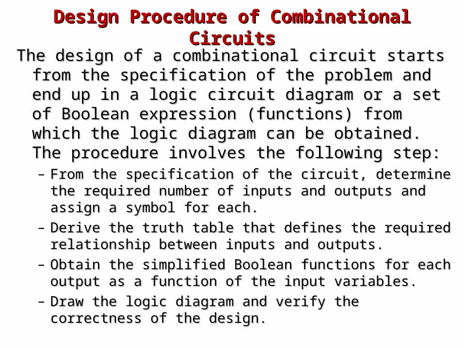
The design of a combinational circuit starts from the The design of a combinational circuit starts from the specification of the problem and end up in a logic specification of the problem and end up in a logic circuit diagram or a set of Boolean expression circuit diagram or a set of Boolean expression (functions) from which the logic diagram can be (functions) from which the logic diagram can be obtained. The procedure involves the following step:obtained. The procedure involves the following step:– From the specification of the circuit, determine the From the specification of the circuit, determine the
required number of inputs and outputs and assign a required number of inputs and outputs and assign a symbol for each.symbol for each.
– Derive the truth table that defines the required Derive the truth table that defines the required relationship between inputs and outputs.relationship between inputs and outputs.
– Obtain the simplified Boolean functions for each output as Obtain the simplified Boolean functions for each output as a function of the input variables.a function of the input variables.
– Draw the logic diagram and verify the correctness of the Draw the logic diagram and verify the correctness of the design.design.
Design Procedure of Combinational CircuitsDesign Procedure of Combinational Circuits
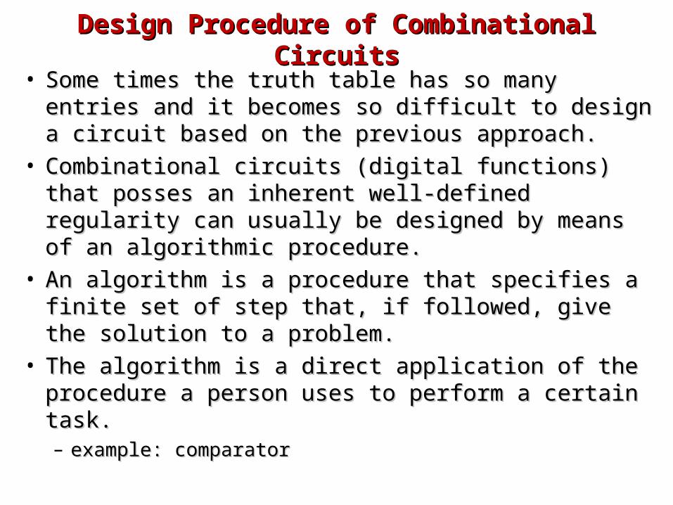
• Some times the truth table has so many entries and Some times the truth table has so many entries and it becomes so difficult to design a circuit based on it becomes so difficult to design a circuit based on the previous approach. the previous approach.
• Combinational circuits (digital functions) that posses Combinational circuits (digital functions) that posses an inherent well-defined regularity can usually be an inherent well-defined regularity can usually be designed by means of an algorithmic procedure.designed by means of an algorithmic procedure.
• An algorithm is a procedure that specifies a finite An algorithm is a procedure that specifies a finite set of step that, if followed, give the solution to a set of step that, if followed, give the solution to a problem.problem.
• The algorithm is a direct application of the The algorithm is a direct application of the procedure a person uses to perform a certain task. procedure a person uses to perform a certain task. – example: comparatorexample: comparator
Half-AdderHalf-Adder
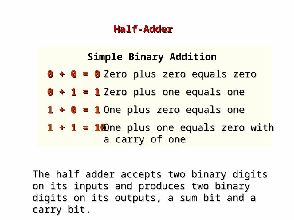
0 + 0 = 00 + 0 = 0
0 + 1 = 10 + 1 = 1
1 + 0 = 11 + 0 = 1
1 + 1 = 101 + 1 = 10
Zero plus zero equals zeroZero plus zero equals zero
Zero plus one equals oneZero plus one equals one
One plus zero equals oneOne plus zero equals one
One plus one equals zero with a carry One plus one equals zero with a carry of oneof one
Simple Binary Addition
The half adder accepts two binary digits on its inputs The half adder accepts two binary digits on its inputs and produces two binary digits on its outputs, a sum bit and produces two binary digits on its outputs, a sum bit and a carry bit. and a carry bit.

Half-Adder Half-Adder
Logic symbol
Logic diagram
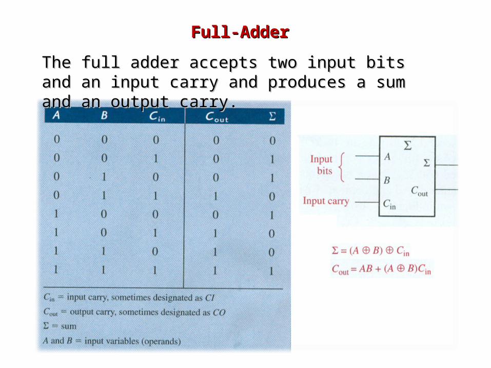
Full-AdderFull-Adder
The full adder accepts two input bits and an input carry The full adder accepts two input bits and an input carry and produces a sum and an output carry.and produces a sum and an output carry.

Full-Adder Full-Adder
Full-adder logic.Full-adder logic.

Full-AdderFull-Adder
• Full adder from two half-adder circuitsFull adder from two half-adder circuits
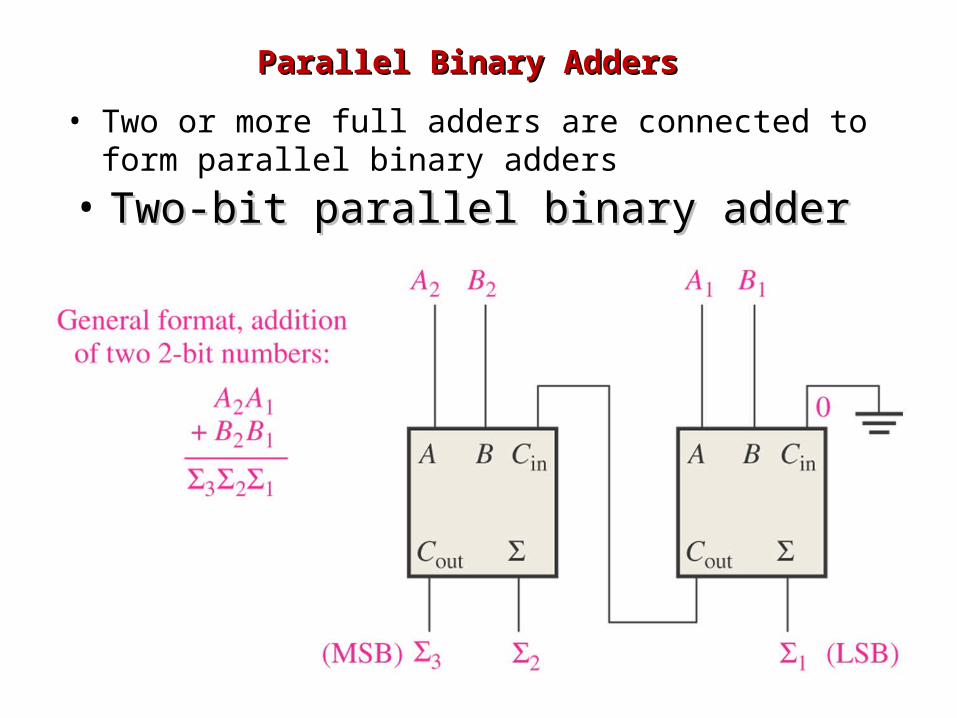
Parallel Binary AddersParallel Binary Adders
• Two-bit parallel binary adderTwo-bit parallel binary adder
• Two or more full adders are connected to form parallel binary adders
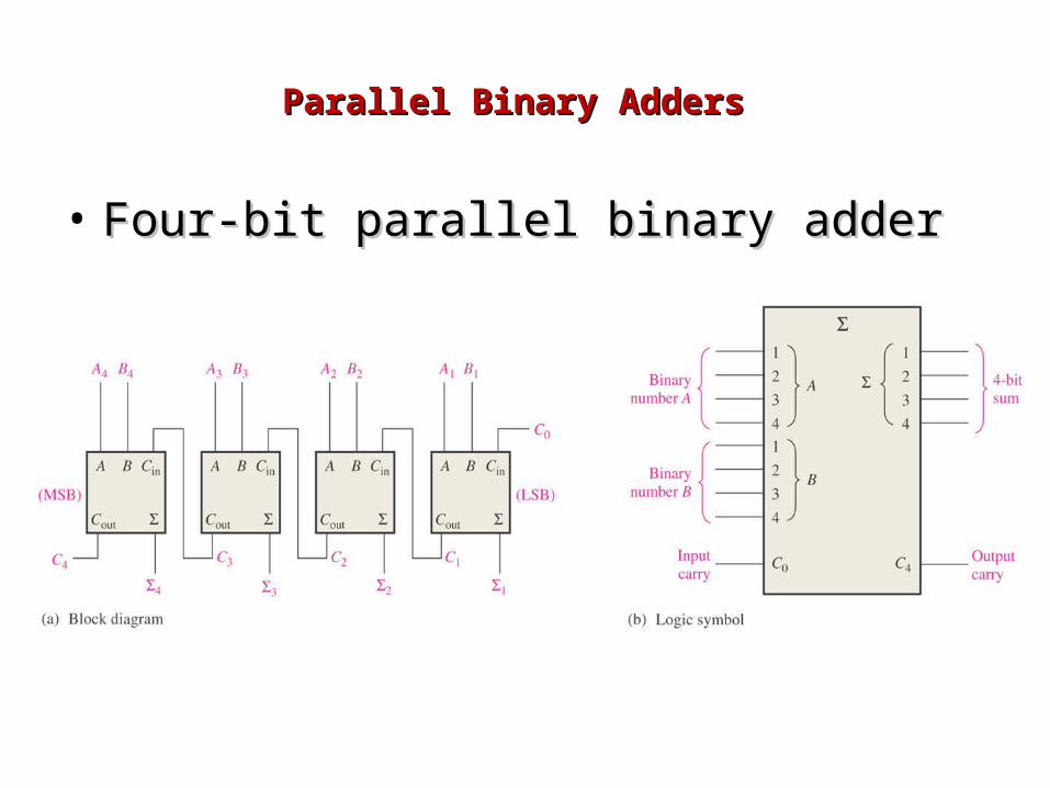
Parallel Binary AddersParallel Binary Adders
• Four-bit parallel binary adderFour-bit parallel binary adder
Application: a voting system using full adders Application: a voting system using full adders and binary addersand binary adders
• Self study. See pages 281 and 282 in the Self study. See pages 281 and 282 in the textbook.textbook.

Binary SubtractorBinary Subtractor• The Subtraction A – B can be done by taking the The Subtraction A – B can be done by taking the
2’s complement (1’s complement + 1) of B and 2’s complement (1’s complement + 1) of B and adding it to A.adding it to A.
• 1’s complement is implemented with inverters.1’s complement is implemented with inverters.• The subtractor A – B is implemented by using The subtractor A – B is implemented by using
adders and inverters.adders and inverters.
• The input carry of CThe input carry of C inin of the 1 of the 1stst adder must be equal adder must be equal
to 1.to 1.• The operation becomes:The operation becomes:
A + 1’s complement of B + 1.A + 1’s complement of B + 1.• Example: Design 2 bit subtractor.Example: Design 2 bit subtractor.
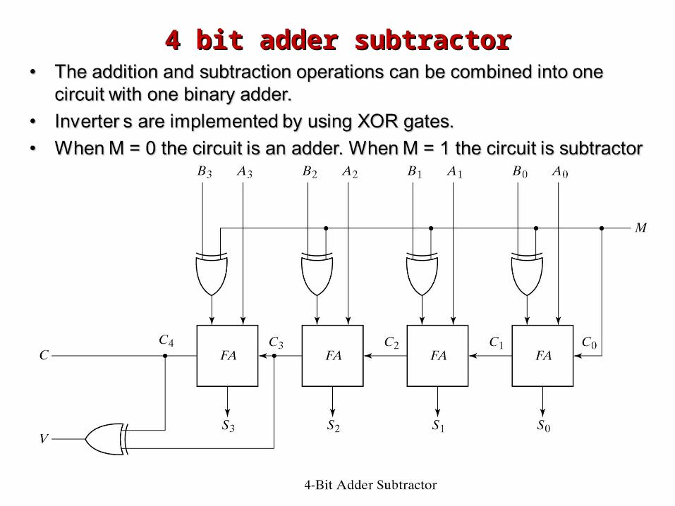
4 bit adder subtractor4 bit adder subtractor
ComparatorsComparators
• The basic function of a comparator is to The basic function of a comparator is to compare the magnitudes of two binary compare the magnitudes of two binary quantities to determine the relationship quantities to determine the relationship of those quantities.of those quantities.– 1-Bit Comparator1-Bit Comparator– 2-Bit Comparator2-Bit Comparator– 4-Bit Comparator4-Bit Comparator
ComparatorsComparators
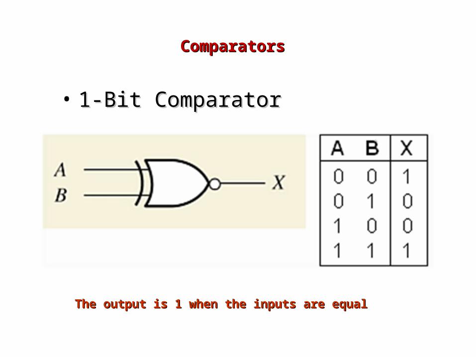
• 1-Bit Comparator1-Bit Comparator
The output is 1 when the inputs are equalThe output is 1 when the inputs are equal
ComparatorsComparators
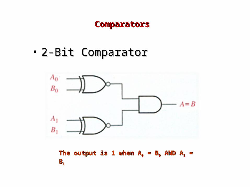
• 2-Bit Comparator2-Bit Comparator
The output is 1 when AThe output is 1 when A00 = B = B00 AND A AND A11 = B = B11
Comparators Comparators
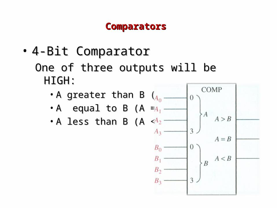
• 4-Bit Comparator4-Bit ComparatorOne of three outputs will be HIGH:One of three outputs will be HIGH:
• A greater than B (A > B)A greater than B (A > B)• A equal to B (A = B)A equal to B (A = B)• A less than B (A < B)A less than B (A < B)
Designing the 4-bit comparatorDesigning the 4-bit comparator

DecodersDecoders
• Binary decoderBinary decoder
• 4-bit decoder4-bit decoder
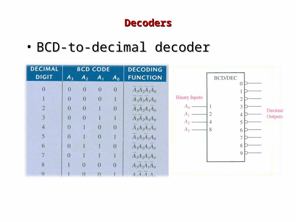
• BCD-to-decimal decoderBCD-to-decimal decoder
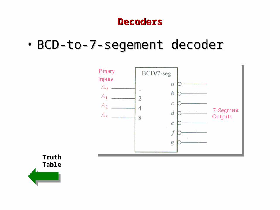
• BCD-to-7-segement decoderBCD-to-7-segement decoder
DecodersDecoders
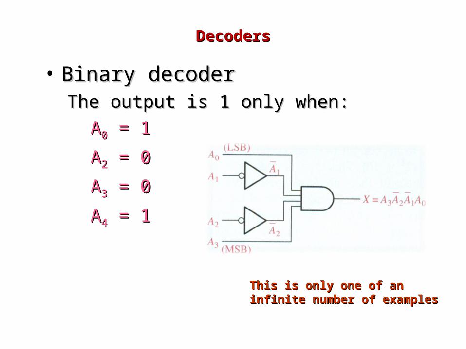
• Binary decoderBinary decoderThe output is 1 only when: The output is 1 only when:
AA00 = 1 = 1
AA22 = 0 = 0
AA33 = 0 = 0
AA44 = 1 = 1
This is only one of an infinite This is only one of an infinite number of examplesnumber of examples

DecodersDecoders
• 4-bit decoder4-bit decoder
LogicLogicDiagramDiagram
DecodersDecoders
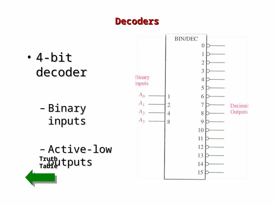
• 4-bit decoder4-bit decoder
– Binary inputsBinary inputs
– Active-low Active-low outputsoutputs
TruthTruthTableTable
DecodersDecoders
• BCD-to-decimal decoderBCD-to-decimal decoder

DecodersDecoders
• BCD-to-7-segement decoderBCD-to-7-segement decoder
LogicLogicDiagramDiagram
DecodersDecoders
• BCD-to-7-segement decoderBCD-to-7-segement decoder
TruthTruthTableTable
Encoders Encoders
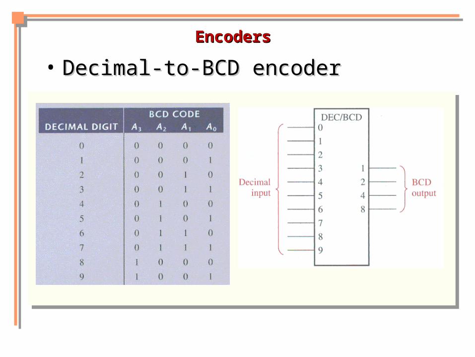
• Decimal-to-BCD encoderDecimal-to-BCD encoder
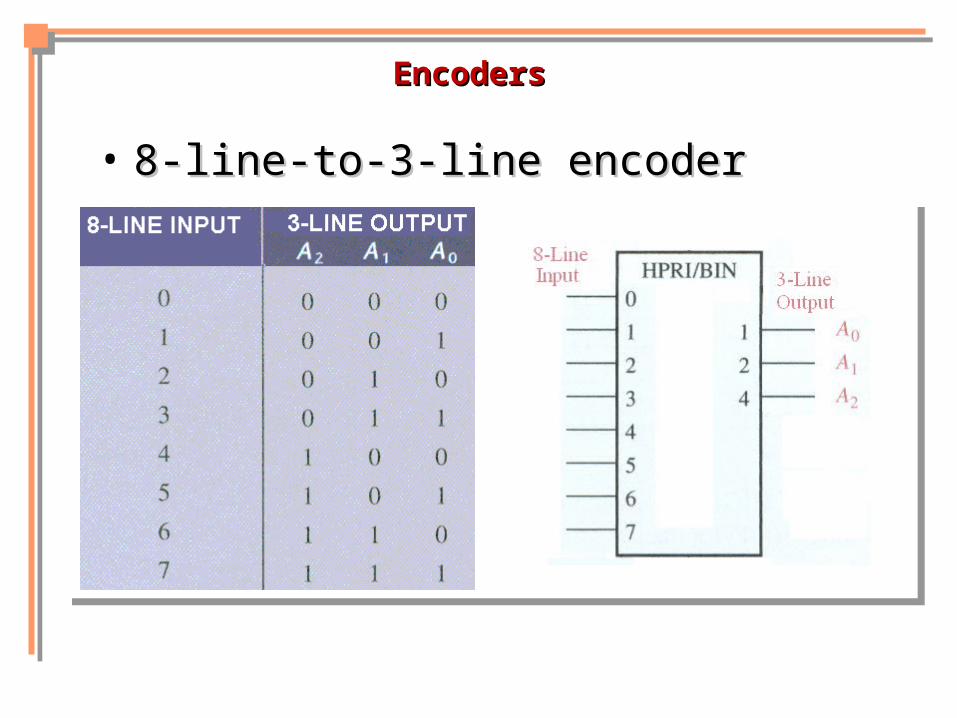
• 8-line-to-3-line encoder8-line-to-3-line encoder
Encoders Encoders
• Decimal-to-BCD encoderDecimal-to-BCD encoder
Encoders Encoders
• 8-line-to-3-line encoder8-line-to-3-line encoder
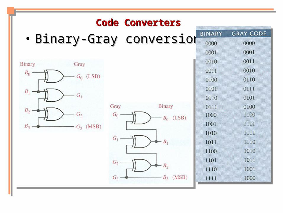
Code Converters Code Converters
Code ConvertersCode Converters
• BCD-to-binary conversionBCD-to-binary conversion
• Binary-Gray conversionsBinary-Gray conversions
Code ConvertersCode Converters
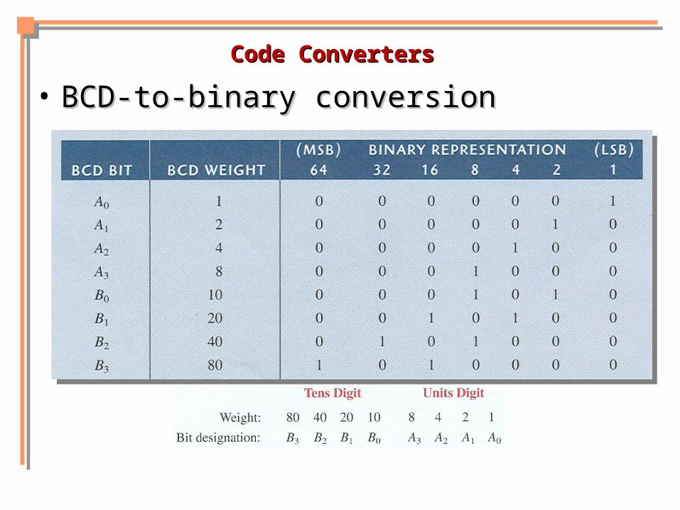
• BCD-to-binary conversionBCD-to-binary conversion
Code ConvertersCode Converters
• Binary-Gray conversionsBinary-Gray conversions
Multiplexers (Data Selectors) Multiplexers (Data Selectors)
Multiplexers (Data Selectors)Multiplexers (Data Selectors)
• 4-input multiplexer4-input multiplexer
• Expanded multiplexersExpanded multiplexers
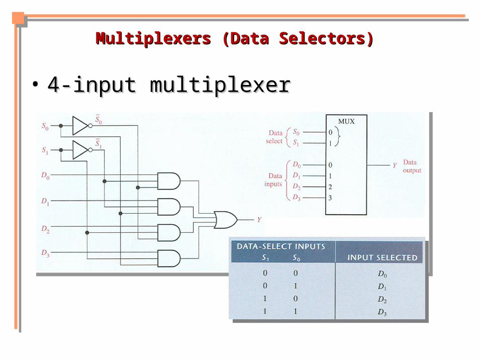
Multiplexers (Data Selectors)Multiplexers (Data Selectors)
• 4-input multiplexer4-input multiplexer

Multiplexers (Data Selectors)Multiplexers (Data Selectors)
• Expanded multiplexersExpanded multiplexers

Demultiplexers Demultiplexers

DemultiplexersDemultiplexers
• 2-line-to4-line demux2-line-to4-line demux
Parity Generator/Checker Parity Generator/Checker
Parity Generator/Checker Parity Generator/Checker
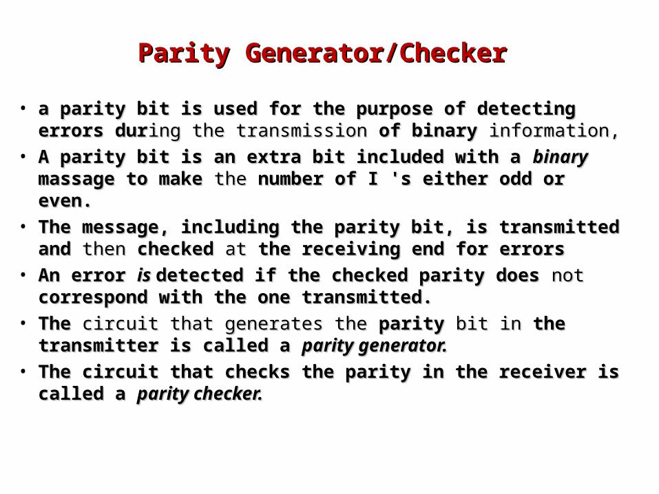
• a parity bit is used for the purpose of detecting errors a parity bit is used for the purpose of detecting errors durduring the transmission ing the transmission of binary of binary information, information,
• A parity bit is an extra bit included with a A parity bit is an extra bit included with a binary binary massage to make massage to make the the number of I 's either odd or even.number of I 's either odd or even.
• The message, including the parity bit, is transmitted The message, including the parity bit, is transmitted and and then then checked checked at at the receiving end for errorsthe receiving end for errors
• An error An error is is detected if the checked parity does detected if the checked parity does not not correspond with the one transmitted.correspond with the one transmitted.
• The The circuit that generates the circuit that generates the parity parity bit in bit in the transmitter the transmitter is called a is called a parity generator. parity generator.
• The circuit that checks the parity in the receiver is The circuit that checks the parity in the receiver is called a called a parity checker.parity checker.
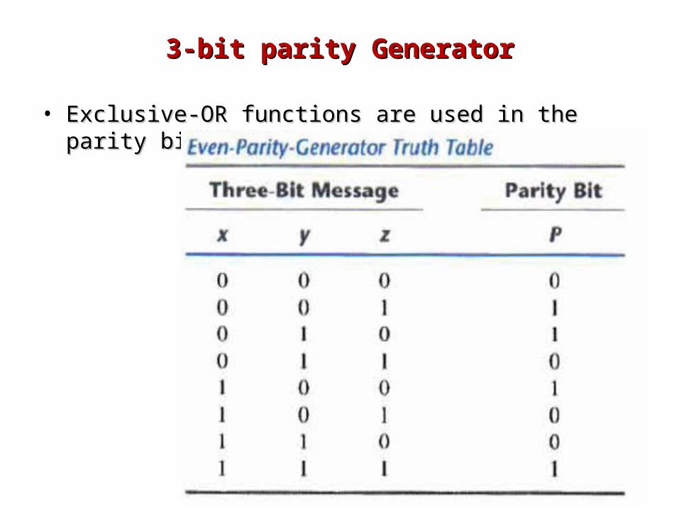
3-bit parity Generator3-bit parity Generator
• Exclusive-OR functions are used in the parity bit Exclusive-OR functions are used in the parity bit generator.generator.
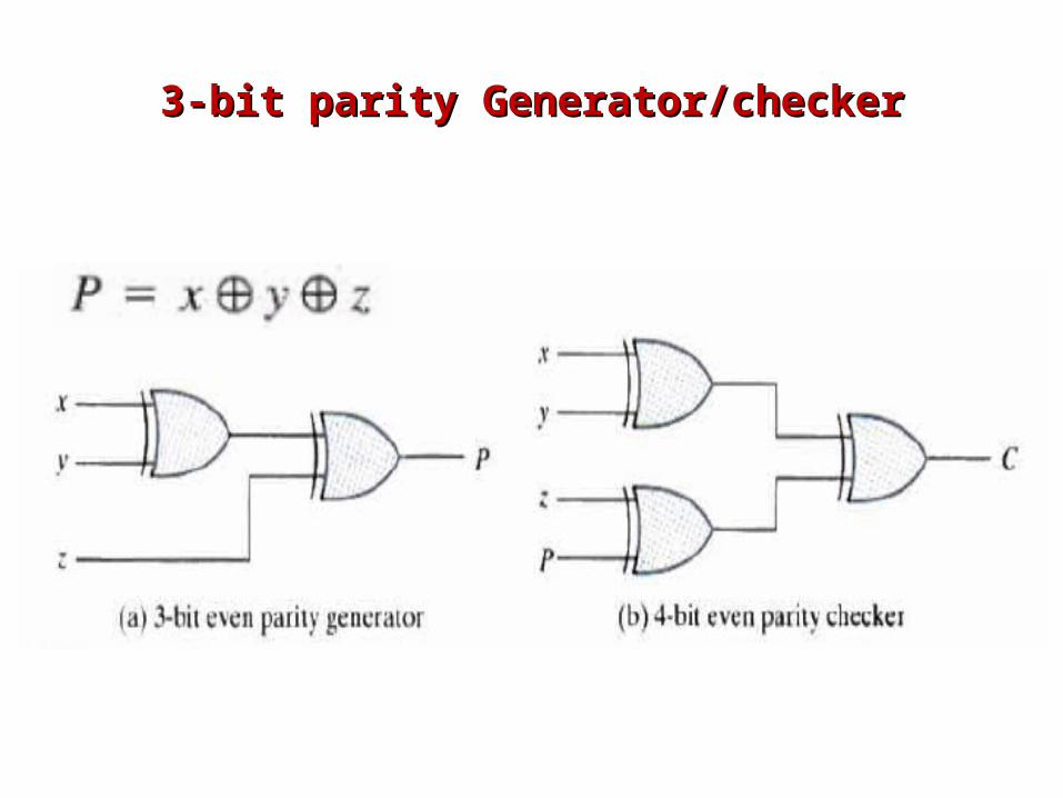
3-bit parity Generator/checker3-bit parity Generator/checker
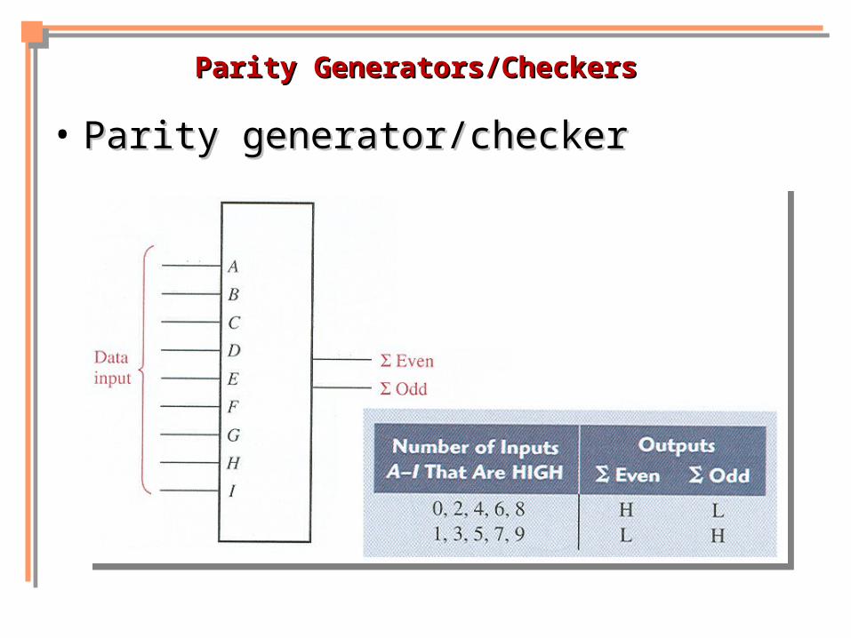
Parity Generators/CheckersParity Generators/Checkers
• Parity generator/checkerParity generator/checker

These slides are based on Digital Fundamentals 9These slides are based on Digital Fundamentals 9 thth ed. By Thomas Floyd ed. By Thomas Floyd