FT900 SERIES DISHWASHERS - Hobart manual.pdf · Positioning the Center Section ... Checking...
40
FT900 SERIES DISHWASHERS MODELS ML-110668-U covers all of the following models: FT900 FT900BD FT900S FT900SBD FT900D FT900DBD FT900SD FT900SDBD 701 S. RIDGE AVENUE TROY, OHIO 45374-0001 937 332-3000 www.hobartcorp.com FORM 44093 Rev. A (Dec. 2010)
Transcript of FT900 SERIES DISHWASHERS - Hobart manual.pdf · Positioning the Center Section ... Checking...

FT900 SERIES DISHWASHERS
MODELS ML-110668-U covers all of the following models:
FT900 FT900BD
FT900S FT900SBD
FT900D FT900DBD
FT900SD FT900SDBD
701 S. RIDGE AVENUETROY, OHIO 45374-0001
937 332-3000
www.hobartcorp.com FORM 44093 Rev. A (Dec. 2010)

– 2 –© HOBART 2010
TABLE OF CONTENTSNOTES FOR THE INSTALLERS . . . . . . . . . . . . . . . . . . . . . . . . . . . . . . . . . . . . . . . . . . . . . . . . . . . . . . . 4 How to Reduce Clearance Height of the Control Box During Move-In . . . . . . . . . . . . . . . . . . . . . . 5
UNPACKING . . . . . . . . . . . . . . . . . . . . . . . . . . . . . . . . . . . . . . . . . . . . . . . . . . . . . . . . . . . . . . . . . . . . . . 6 Removing Each Section from Its Skid . . . . . . . . . . . . . . . . . . . . . . . . . . . . . . . . . . . . . . . . . . . . . . . 6
LOCATION . . . . . . . . . . . . . . . . . . . . . . . . . . . . . . . . . . . . . . . . . . . . . . . . . . . . . . . . . . . . . . . . . . . . . . . 7 Positioning the Center Section . . . . . . . . . . . . . . . . . . . . . . . . . . . . . . . . . . . . . . . . . . . . . . . . . . . . . 7 Leveling the Center Section with Sliding Doors . . . . . . . . . . . . . . . . . . . . . . . . . . . . . . . . . . . . . . . . 7 Leveling the Center Section with Hinged Doors . . . . . . . . . . . . . . . . . . . . . . . . . . . . . . . . . . . . . . . . 8
ASSEMBLY . . . . . . . . . . . . . . . . . . . . . . . . . . . . . . . . . . . . . . . . . . . . . . . . . . . . . . . . . . . . . . . . . . . . . . . 9 Rotating Control Box 90 Degrees . . . . . . . . . . . . . . . . . . . . . . . . . . . . . . . . . . . . . . . . . . . . . . . . . . 9 Installing Foam Tape on Chamber Flanges and Control Box Mounting Surface . . . . . . . . . . . . . . . 9 Positioning the Adjacent Load or Unload Sections . . . . . . . . . . . . . . . . . . . . . . . . . . . . . . . . . . . . . 9 Leveling the Load and Unload Sections . . . . . . . . . . . . . . . . . . . . . . . . . . . . . . . . . . . . . . . . . . . . . 10 Joining the Sections Together . . . . . . . . . . . . . . . . . . . . . . . . . . . . . . . . . . . . . . . . . . . . . . . . . . . . 10 Installing the Curtain Baffl es – Top of Chamber Flanges . . . . . . . . . . . . . . . . . . . . . . . . . . . . . . . . 10 Installing the Saddle Joint – Bottom of Chamber Flanges . . . . . . . . . . . . . . . . . . . . . . . . . . . . . . .11 Saddle Installation for Split Load or Split Unload Sections . . . . . . . . . . . . . . . . . . . . . . . . . . . . . . 12 Installing the End Caps – Bottom of Chamber Flanges . . . . . . . . . . . . . . . . . . . . . . . . . . . . . . . . . 12 Assembling Spreader Bar to Base Frame Behind Control Box . . . . . . . . . . . . . . . . . . . . . . . . . . . 14 Attaching Control Box to Unload Section . . . . . . . . . . . . . . . . . . . . . . . . . . . . . . . . . . . . . . . . . . . . 14 Control Box Connections . . . . . . . . . . . . . . . . . . . . . . . . . . . . . . . . . . . . . . . . . . . . . . . . . . . . . . . . 15 Installing the Flowback Pipe (Wash to Prewash Tanks) . . . . . . . . . . . . . . . . . . . . . . . . . . . . . . . . . 16 Installing the Dual Rinse Flowback Pipe (FT900D & FT900SD only) . . . . . . . . . . . . . . . . . . . . . . 16 Installing the Drain Pipe . . . . . . . . . . . . . . . . . . . . . . . . . . . . . . . . . . . . . . . . . . . . . . . . . . . . . . . . . 17 Checking Operation of Dish Limit Switch . . . . . . . . . . . . . . . . . . . . . . . . . . . . . . . . . . . . . . . . . . . . 17 Checking the Positions of the Drainback Pans . . . . . . . . . . . . . . . . . . . . . . . . . . . . . . . . . . . . . . . 17 Dual Rinse Drainback Pan Installation – Models FT900D & FT900SD . . . . . . . . . . . . . . . . . . . . . 18 Blower-Dryer Assembly . . . . . . . . . . . . . . . . . . . . . . . . . . . . . . . . . . . . . . . . . . . . . . . . . . . . . . . . . 20
ELECTRICAL CONNECTION(S) . . . . . . . . . . . . . . . . . . . . . . . . . . . . . . . . . . . . . . . . . . . . . . . . . . . . . 22 Checking Motor Rotation (Three-Phase Motors) . . . . . . . . . . . . . . . . . . . . . . . . . . . . . . . . . . . . . . 22 Separate Electrical Connections . . . . . . . . . . . . . . . . . . . . . . . . . . . . . . . . . . . . . . . . . . . . . . . . . . 22 Voltage Adjustment . . . . . . . . . . . . . . . . . . . . . . . . . . . . . . . . . . . . . . . . . . . . . . . . . . . . . . . . . . . . 22 Prewash Door Interlock(s) – Sliding and Hinged Doors . . . . . . . . . . . . . . . . . . . . . . . . . . . . . . . . . 23 Electrical Connection – Rinse Aid & Detergent Dispensers . . . . . . . . . . . . . . . . . . . . . . . . . . . . . . 23 Vent Fan Control . . . . . . . . . . . . . . . . . . . . . . . . . . . . . . . . . . . . . . . . . . . . . . . . . . . . . . . . . . . . . . 23

– 3 –
Do not throw out any loose parts. These may be required for installation or operation.
PLUMBING CONNECTIONS . . . . . . . . . . . . . . . . . . . . . . . . . . . . . . . . . . . . . . . . . . . . . . . . . . . . . . . . 24 Water Supply . . . . . . . . . . . . . . . . . . . . . . . . . . . . . . . . . . . . . . . . . . . . . . . . . . . . . . . . . . . . . . . . . 24 Fill . . . . . . . . . . . . . . . . . . . . . . . . . . . . . . . . . . . . . . . . . . . . . . . . . . . . . . . . . . . . . . . . . . . . . . . . . . 24 Final Rinse . . . . . . . . . . . . . . . . . . . . . . . . . . . . . . . . . . . . . . . . . . . . . . . . . . . . . . . . . . . . . . . . . . . 24 Drain . . . . . . . . . . . . . . . . . . . . . . . . . . . . . . . . . . . . . . . . . . . . . . . . . . . . . . . . . . . . . . . . . . . . . . . . 24 Line Strainers . . . . . . . . . . . . . . . . . . . . . . . . . . . . . . . . . . . . . . . . . . . . . . . . . . . . . . . . . . . . . . . . 24 Steam Supply (When Equipped) . . . . . . . . . . . . . . . . . . . . . . . . . . . . . . . . . . . . . . . . . . . . . . . . . . 25 Steam Tank Heaters – Condensate Return Lines . . . . . . . . . . . . . . . . . . . . . . . . . . . . . . . . . . . . . 25 Steam Booster Heater – Condensate Return Line and Relief Valves . . . . . . . . . . . . . . . . . . . . . . 25 Steam Blower-Dryer (When Equipped) . . . . . . . . . . . . . . . . . . . . . . . . . . . . . . . . . . . . . . . . . . . . . 25CONVEYOR ASSEMBLY . . . . . . . . . . . . . . . . . . . . . . . . . . . . . . . . . . . . . . . . . . . . . . . . . . . . . . . . . . . 26 Loading and Joining the Conveyor Sections . . . . . . . . . . . . . . . . . . . . . . . . . . . . . . . . . . . . . . . . . 26 Conveyor Offset Link . . . . . . . . . . . . . . . . . . . . . . . . . . . . . . . . . . . . . . . . . . . . . . . . . . . . . . . . . . . 27 Adjusting the Conveyor Take-up Unit (Prewash Section) . . . . . . . . . . . . . . . . . . . . . . . . . . . . . . . 29MISCELLANEOUS . . . . . . . . . . . . . . . . . . . . . . . . . . . . . . . . . . . . . . . . . . . . . . . . . . . . . . . . . . . . . . . . 30 Vent Duct . . . . . . . . . . . . . . . . . . . . . . . . . . . . . . . . . . . . . . . . . . . . . . . . . . . . . . . . . . . . . . . . . . . . 30 Prewash, Wash and Power Rinse Arms . . . . . . . . . . . . . . . . . . . . . . . . . . . . . . . . . . . . . . . . . . . . 30 Final Rinse Arms . . . . . . . . . . . . . . . . . . . . . . . . . . . . . . . . . . . . . . . . . . . . . . . . . . . . . . . . . . . . . . 30 Dual Rinse Arms – Models FT900D & FT900SD . . . . . . . . . . . . . . . . . . . . . . . . . . . . . . . . . . . . . . 30 Curtains and Drainback Pans, Model FT900 . . . . . . . . . . . . . . . . . . . . . . . . . . . . . . . . . . . . . . . . . 31 Curtains and Drainback Pans, Model FT900D . . . . . . . . . . . . . . . . . . . . . . . . . . . . . . . . . . . . . . . . 32 Curtains and Drainback Pans, Model FT900S . . . . . . . . . . . . . . . . . . . . . . . . . . . . . . . . . . . . . . . . 33 Curtains and Drainback Pans, Model FT900SD . . . . . . . . . . . . . . . . . . . . . . . . . . . . . . . . . . . . . . 34 Conveyor Gearmotor . . . . . . . . . . . . . . . . . . . . . . . . . . . . . . . . . . . . . . . . . . . . . . . . . . . . . . . . . . . 35 Lower Trim Panels (Front) . . . . . . . . . . . . . . . . . . . . . . . . . . . . . . . . . . . . . . . . . . . . . . . . . . . . . . . 35 Rear Panels . . . . . . . . . . . . . . . . . . . . . . . . . . . . . . . . . . . . . . . . . . . . . . . . . . . . . . . . . . . . . . . . . . 35 Calibrating the Electric Booster Thermostat . . . . . . . . . . . . . . . . . . . . . . . . . . . . . . . . . . . . . . . . . . 36
Setup Procedure for Energy Recovery (When Equipped) . . . . . . . . . . . . . . . . . . . . . . . . . . . . . . . 37
SERVICE . . . . . . . . . . . . . . . . . . . . . . . . . . . . . . . . . . . . . . . . . . . . . . . . . . . . . . . . . . . . . . . . . . . . . . . . 39
– 4 –
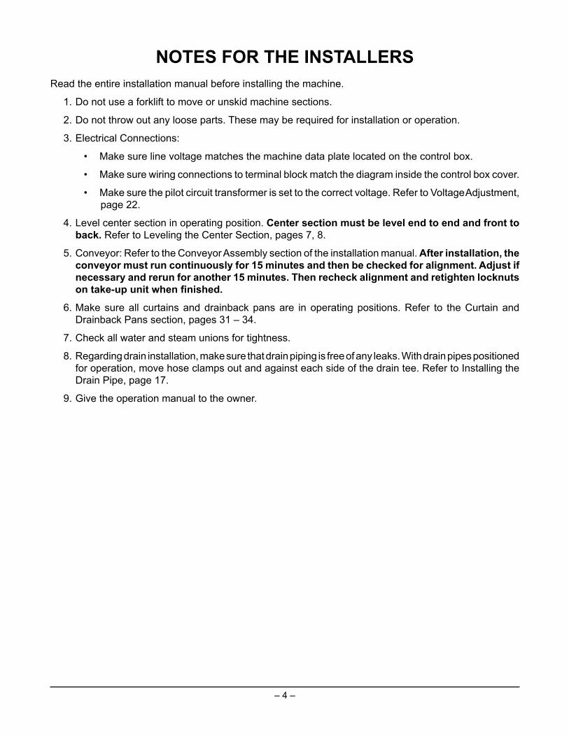
NOTES FOR THE INSTALLERSRead the entire installation manual before installing the machine.
1. Do not use a forklift to move or unskid machine sections.
2. Do not throw out any loose parts. These may be required for installation or operation.
3. Electrical Connections:
• Make sure line voltage matches the machine data plate located on the control box.
• Make sure wiring connections to terminal block match the diagram inside the control box cover.
• Make sure the pilot circuit transformer is set to the correct voltage. Refer to Voltage Adjustment, page 22.
4. Level center section in operating position. Center section must be level end to end and front to back. Refer to Leveling the Center Section, pages 7, 8.
5. Conveyor: Refer to the Conveyor Assembly section of the installation manual. After installation, the conveyor must run continuously for 15 minutes and then be checked for alignment. Adjust if necessary and rerun for another 15 minutes. Then recheck alignment and retighten locknuts on take-up unit when fi nished.
6. Make sure all curtains and drainback pans are in operating positions. Refer to the Curtain and Drainback Pans section, pages 31 – 34.
7. Check all water and steam unions for tightness.
8. Regarding drain installation, make sure that drain piping is free of any leaks. With drain pipes positioned for operation, move hose clamps out and against each side of the drain tee. Refer to Installing the Drain Pipe, page 17.
9. Give the operation manual to the owner.

– 5 –
How to Reduce the Clearance Height of the Control Box During Move-In
This procedure will reduce the overall height of the dishwasher by 11/8" to allow it to travel througha low-height corridor or doorway.
1. Remove upper shipping hinge by unscrewing two 5/16 -18 bolts, lockwashers, washers andnuts.
2. Remove lower shipping hinge by unscrewing two U-bolts and one other 5/16 -18 bolt withlockwashers, washers and nuts.
3. Save all removed materials.
The control box must be securely supported by at least two people while itsmounting studs are being shifted to lower slots of the shipping braces.
The rear of the main control box (Fig. 1) is attached to the two shipping braces on the centersection by four 5/16 -18 threaded studs, lockwashers, washers and nuts. The shipping braceshave slots that allow the control box to be lowered by 11/8".
4. While two people securely support the main control box, remove the four 5/16 -18 nuts andlockwashers from the main control box's rear studs that project through the shipping braces.
5. At least two people should CAREFULLY CONTROL and withdraw the main control box'srear studs from the center section's shipping braces. Lower the main control box's threadedstuds to the next lower slots. Refasten the main control box's threaded studs with the same5/16 -18 bolts, lockwashers and nuts removed in step 4.
6. Move the dishwasher past all low-height corridors or doorways.
7. Reverse steps 5, 4, 2 and 1 to return the main control box to its shipping condition for properinstallation.
Fig. 1

– 6 –
UNPACKING
Immediately after unpacking the dishwasher, check for possible shipping damage. If the machineis found to be damaged, save the packaging material and contact the carrier within 15 days ofdelivery.
Before installation, test the electrical service to make sure it agrees with the specifications on themachine data plate located on the control box. The electrical diagram is located inside the controlbox door.
Strainer baskets, strainer pans, pump inlet strainers and wash arms are taped and shipped inplace. Remove tape, but retain all parts in their proper places. If any parts are temporarilyremoved during installation, return them to their proper places after installation is complete.
Before installing, check to make sure that necessary electrical, plumbing and exhaustaccommodations are provided at the installation location. Take measurements of site’s plumbing,electrical and exhaust connections; then take corresponding measurements of the machine tomake sure all connections are correctly mated. If necessary to lower control box during move-in, slotted holes are provided on the control box shipping braces to allow adjustment for clearanceheight. Refer to page 5.
REMOVING EACH SECTION FROM ITS SKID
Do not use a forklift to move or unskid machine sections. Doing so may result indamage to the machine.
1. Remove the lag bolts that are securing the crossmembers to the front and rear runners.
2. Remove the lag bolts from the leg shipping brackets.
3. Carefully raise one end of the section just enough to slide the skid rails from under it andremove the leg shipping brackets.
4. Repeat steps 1 through 3 at the other end.
5. Thread the feet into the legs as far as possible; then back out three full turns. Standard legshave 3" threaded studs for maximum adjustment. If special feet were ordered with extra longleg shanks to accommodate a highly sloped floor, install them where the low points in thefloor occur at leg locations on the machine before setting the unit on the floor.
6. Open all inspection doors and remove all wrapped parts and boxes from inside eachmachine section.
7. Remove any packaging, tape, wire and bracing from each section. Remove all rear andlower panels.
8. Verify that shipping tape has been removed from all floats in each tank and that the floatsare free to operate properly.
NOTE: Do not throw out any loose parts. These may be required for installation or operation.

– 7 –
LOCATION
Allow adequate space for machine installation and operation. Place the machine sections closeto their final position. Allow space to work on the ends of the center section.
Review, but do not remove, tags or labels. Remove tags after installation is complete.
POSITIONING THE CENTER SECTION
Use a chalk line on the floor to align the machine along its complete length.
With each section in its approximate final position, determine which section is at the high pointon the floor. Machine assembly begins after the center section has been leveled to a heightthat compensates for the floor height of the other sections.
LEVELING THE CENTER SECTION WITH SLIDING DOORS
With the center section is in its final operating position, it must be leveled at a height that allowsthe other sections to be level.
• Level the center section along its length by placing the level at various points along the tanksupport rails (Fig. 2) and threading the feet in or out as required.
• Level the center section front to back by placing the level on top of the chamber at each end(Fig. 3).
Fig. 2 Fig. 3
SET LEVEL ON TANK SUPPORT RAIL

– 8 –
LEVELING THE CENTER SECTION WITH HINGED DOORS
Fig. 4 Fig. 5
For center sections with hinged doors (Fig. 4), leveling is an important installation functionbecause it could affect door operation and cause leaks once the machine is operating.
• Level the center section along its length by opening the doors and placing the level betweenthe doors along the tank support rail (Fig. 5) or on top of the chamber front (Fig. 6). Do notcheck level on top of doors. Adjust the feet in or out as required to level.
• Continue to level the center section front to back by placing the level across the top cornersof the chambers on both ends of center section (Fig. 7).
• NOTE: Do not adjust doors until the machine is completely assembled and ready for initialtesting with the pumps running.
Fig. 6 Fig. 7

– 9 –
ASSEMBLY
ROTATING CONTROL BOX 90 DEGREES
The main control box is shipped with upper and lower shipping hinges connected to the centersection. Loosen the control box from the shipping braces and remove the shipping braces. Usethe upper shipping hinges (Fig. 8) to rotate the control box 90 degrees. Do not remove the uppershipping hinges until after the unload and center sections are joined.
Pull the control box out about 1" to allow mating of center and unload sections withoutinterference with studs projecting from rear of control box.
Fig. 8 Fig. 9
INSTALLING FOAM TAPE ON CHAMBER FLANGES & CONTROL BOX MOUNTING SURFACE
Cut strips of vinyl foam tape to fit the top, bottom and sides of the chamber flanges of the load,unload and both ends of the center section to make a good seal (Fig. 9). Apply foam tape,provided, to unload section where the rear perimeter of the control box will be mounted.
POSITIONING THE ADJACENT LOAD OR UNLOAD SECTIONS
Move the adjoining (load or unload) section to within several inches of the prepared end of thecenter section. Adjust the feet of the section adjacent to the leveled center section so tanksupports are the same height. Peel the protective paper from the vinyl foam tape and move thesecond section to its final position. Be very careful that mating components connect and fittogether properly.
NOTE: On models FT900 and FT900D, insert the flowback pipe in the coupling on the prewashtank so the notched end faces the wash tank coupling. Refer to page 16 and Fig. 21.
VINYL FOAM TAPEON CHAMBER FLANGES OF ALL MATING SECTIONS
PL-41067a

– 10 –
LEVELING THE LOAD AND UNLOAD SECTIONS
The tank support rails should be level across the entire length of the machine (Fig. 5). Sections to bemated should be level front to back (Fig. 7). Refer to page 8.
• Abutted sections are parallel; the foam tape line is vertical (Fig. 10).
• All adjoining components of the two sections are exactly in line with each other.
• Top corners of adjoining sections are the same height.
JOINING THE SECTIONS TOGETHER
On models FT900D and FT900SD, remove the dual rinse pan support brackets before joining the twosections at the unload end together. Reinstall the dual rinse pan support brackets in their originalshipped positions after the two sections at the unload end have been joined.
Use drift pins to align the holes in the horizontal and vertical chamber flanges of the mated sections.Use C-clamps to hold the sections in position while bolting the chamber front and back flanges together(Fig. 11). Exercise care to avoid tearing the foam tape seal.
Fig. 10 Fig. 11
When installing a blower-dryer unload section, remove the air deflector pans. Do not stand,sit or lie on them. Blower-dryer performance could be compromised.
INSTALLING THE CURTAIN BAFFLES — TOP OF CHAMBER FLANGES
Install one curtain baffle on each side of the top of the chamber flanges where sections are being joinedusing appropriate fasteners and Permagum, supplied (Fig. 12).
Fig. 12

– 11 –
CHAMBER FLANGE AND BOLT ASSEMBLY AT EACH SECTION JOINT
Description Qty. Bolt Size Assembly Order Instructions
Short Bolt - Use except [Bolt, Washer] Use Permagum on insideswhere Long Bolts or Large 21 1/4-20 x 1" [Washer, Lockwasher, Nut] of washers on both sides ofBolts are required. chamber flanges.
Long Bolt - Use on Saddle [Bolt, Washer] Use Permagum on insidesJoints and End Caps 11 1/4-20 x 11/8" [Washer, Lockwasher, Nut] of washers on both sides of
saddle joints and End Caps
Large Bolt - Use behind [Bolt, Washer] Use Permagum on insidesconveyor side rails. 4 5/16-18 x 11/8" [Washer, Lockwasher, Nut] of washers on both sides of
conveyor side rails.
INSTALLING THE SADDLE JOINT — BOTTOM OF CHAMBER FLANGES
1. Seal the tank end flanges where sections join, using a saddle joint and two end caps.
2. Place the saddle joint over the tank end flanges and make sure that all bolt holes are aligned.After verification, remove components.
3. Cut five strips of 1/2"-wide Permagum equal to the length of the saddle joint.
4. Put Permagum on the outside faces of the tank flanges: one strip horizontally at the bottom onboth sides, one strip horizontally over the holes on both sides and one strip on top where the twoflanges butt together (Fig. 13).
Fig. 13
5. Position the saddle joint over the Permagummed tank flanges and align the bolt holes using driftpins (or punches).
6. Bolt the saddle joint to the bottom tank flanges with the three long bolts, nuts, washers andlockwashers provided.
7. Use Permagum on insides of washers on both sides to make an adequate seal. You may haveto use a C-clamp on the saddle and saddle caps to get the hardware started.
NOTE: For ease of installation, do not put Permagum inside saddle joint.

– 12 –
SADDLE INSTALLATION FOR SPLIT LOAD OR SPLIT UNLOAD SECTIONS
Follow steps 1 through 7 on page 11 when installing split load sections or split unload sections; thetwo end caps shown in Fig. 15 are not used when load or unload sections are shipped split.
INSTALLING THE END CAPS — BOTTOM OF CHAMBER FLANGES
1. Fit end caps into position using drift pins and mark lines at their ends. Remove the end caps.
2. Apply a single layer of Permagum to the flange edges, where the top of the end caps will cover.
3. Cut the strips of 1/2"-wide Permagum and apply (Fig. 14) in a double layer over the chamber flanges,where the front edge of the front end cap and the rear edge of the rear end cap are marked.
4. Cut strips of 1/2"-wide Permagum and apply in a single layer where the bottom of the end capswill be located (Fig. 14).
5. Over the rest of the chamber flanges, where the three side holes of the end caps will be located,apply a strip of foam tape up and over to both sides.
6. Cut strips of 1/2"-wide Permagum and apply in a single layer up and over the inside end of the endcaps on both sides, where marked (Fig. 14). Apply a strip of foam tape over the Permagum.
NOTE: For ease of assembly, do not put Permagum inside end caps.
NOTE: Flare end cap as shown (Fig. 17) for ease of assembly.
Fig. 14

– 13 –
7. Position the end caps over the ends of the saddle joint at the bottom corners of the chamberflanges.
Fig. 15
8. Align bolt holes using drift pins (Fig. 16). Flare open ends of saddle end caps for ease of assembly(Fig. 17).
Fig. 16 Fig. 17

– 14 –
9. Bolt end caps through saddle joint slots and chamber flange holes (long bolts, nuts, washersand lockwashers are provided) (Fig. 18). Use Permagum on inside of washers on both sidesto make an adequate seal.
Fig. 18
10. Join all dishwasher sections, as required. Tighten all remaining bolts that connect the chamberflanges. Use Permagum on inside of washers on both sides to make an adequate seal.
ASSEMBLING SPREADER BAR TO BASE FRAME BEHIND CONTROL BOX
Assemble the spreader bar, joining the front base frame of the center and unload sections (Fig. 19).Use 5/16 -18 bolts, lockwashers, washers and nuts, provided.
ATTACHING CONTROL BOX TO UNLOAD SECTION
1. The spreader bar (Fig. 19) provides a support for the bottom of the control box. Use wood blocksto lift and support the control box temporarily (Fig. 19).
2. Remove shipping hinges and position the control box on the unload section in the proper location(align uniformly 1/4" along the edge of the preceding adjacent door, wash FT900S and power-rinse FT900).
3. Secure the control box with the four weld studs on the back of the control box through the holesprovided in the front of the unload section using four 5/16 -18 washers, lockwashers and nuts.
Fig. 19
END CAPS
SADDLE JOINT

– 15 –
CONTROL BOX CONNECTIONS
Refer to the electrical diagram stored inside of the main control box door in a protective plastic bag. After use, make sure that the electrical diagram is returned to the plastic bag.
Although each section is prewired, components in the load and unload sections must be electrically connected to the main control box that is attached to the unload section. All wires that need to be connected are furnished with stripped leads and have crimped barrel terminals for terminal block connections. Also provided are locking plug connectors for control boards.
Run wires in proper routing clips, channels and so forth to openings in the lower rear of the main control box. Specifi c connection locations are shown viewed from the front (Fig. 20). Run wires (in conduit) through conduit fi ttings; run cordage through strain reliefs. Make proper connections for wires and cordage. Properly tighten strain reliefs and conduit fi ttings.
After all wires are routed and connected at terminal block, check to make sure any unused holes are plugged (Figs. 20 and 33).
DO NOT permit electric cables or conduit to touch steam pipes.
When making connections to the terminal block (5TB), torque screws to 12 inch-pounds minimum to secure wires and to avoid damage to terminals.
Fig. 20
Using the supplied NSF-approved sealer, apply a bead of caulk where each side of the control box meets the tank support rails to allow any moisture condensation to drain back into the tank.
HOLE CONDUIT USAGE SIZE 1 1/2" SINGLE & DOUBLE STEAM BOOSTER THERMOSTATS 2 3/4" J8 / LOAD SWITCH BOX 3 3/4" J11 / TANK 3 FLOAT BOX 4 3/4" J13 / TANK 2 FLOAT BOX 5 3/4" J10 / TANK “D” (EXTRA TANK) FLOAT BOX (SEF) 6 1/2" 4MTR / CONVEYOR MOTOR 7 1/2" J9 / UNLOAD SWITCH BOX 8 3/4" J12 / TANK 1 FLOAT BOX 9 1/2" 3MTR / PREWASH PUMP MOTOR 10 1/2" J2 / DOOR INTERLOCKS 11 1/2" J15 / FINAL RINSE THERMISTER 12 1/2" 7MTR / FLUSH PUMP MOTOR 13 3/4" DUAL RINSE HEAT BOX - TANK “D” 14 1/2" J16, ELEC BSTR TEMP PROBE / HIGH LIMIT T-STATS 15 1/2" TANK 1 STEAM HEAT VALVE 16 1/2" TANK 2 STEAM HEAT VALVE 17 1/2" 18 1/2" J3 / WATER VALVES 19 1/2" 8MTR / DUAL RINSE PUMP MOTOR 20 1/2" ENERGY RECOVERY CONTROL CABLE 21 1/2" 1MTR / TANK 1 PUMP MOTOR 22 1/2" 2MTR / TANK 3 PUMP MOTOR 23 1/2" J6 / BOOSTER / ELECTRIC OR STEAM 24 3/4" 25 1" TANK 1 HEAT BOX 26 1" TANK 2 HEAT BOX 27 1" TANK “D” (EXTRA TANK) HEAT BOX (SEF) 28 1/2" BLOWER DRYER STEAM VALVE 29 1" BLOWER DRYER ELECTRIC HEAT
NOTE: IF A HOLE IS NOT USED, COVER IT WITH A HOLE PLUG: FOR .875” DIA. HOLES (1/2” CONDUIT SIZE) USE PLUG NO. PB-004-08 FOR 1.094” DIA. HOLES (3/4” CONDUIT SIZE) USE PLUG NO. PB-005-17 FOR 1.375” DIA. HOLES (1” CONDUIT SIZE) USE PLUG NO. PB-005-16

– 16 –
INSTALLING THE FLOWBACK PIPE (Wash to Prewash Tanks)
Install the flowback pipe between the wash tank and the prewash tank (Fig. 21).
Make sure the flowback pipe is adequately lubricated with Parker "Super-O-Lube" (not supplied) or ahousehold liquid dishwashing detergent. Make sure O-rings are in their proper places on the coupling:Two inside and one on the flange end.
Models FT900, FT900D — use straight pipe.
• With the connecting fitting already mounted on theprewash tank, slide the unnotched end of the flowbackpipe into the coupling so it extends about 6" into theprewash tank.
• Slide the notched end of the flowback pipe into thefitting on the wash tank so the cutout in the end of theflowback pipe mates with the tab in the fitting.
Models FT900S, FT900SD — use swept-end pipe.
• Loosen the nut on the fill piping support clamp and slide the flowback pipe toward the prewashtank. As the straight end of the flowback pipe penetrates the coupling, make sure the notch onthe pipe mates with the rib on the coupling mounted on the prewash tank. The swept end of thepipe will be open upwards in the wash tank.
• Re-tighten the nut on the fill piping support clamp.
INSTALLING THE DUAL RINSE FLOWBACK PIPE
Install the flowback pipe for models FT900D and FT900SD (Fig. 22).
Models FT900D, FT900SD only.
1. Loosely assemble the hose and clamps on the pipe coming out of the fitting on the dual rinse tank.
2. Insert the long end of the flowback pipe into the fitting on the adjoining center tank. The offsetend will probably hang down temporarily.
3. Rotate the offset end of the pipe toalign with the hose.
4. Insert the offset end of the pipe soit is halfway in the hose.
5. Tighten the clamps so one clamptightens to the hose and the pipefrom the dual rinse tank; the otherclamp tightens to the hose and theoffset end of the flowback pipe.
Fig. 21
Fig. 22
DUAL RINSE TANK
DUAL RINSE FLOWBACK PIPE
HOSE & CLAMPSPIPE
FITTING

– 17 –
INSTALLING THE DRAIN PIPE
Install the drain pipe between the adjoining tank sections as follows:
1. Mark the drain pipe 3" from each end with a legible mark. (Use marking pen, lead pencil, etc.)
2. The arrow molded in the drain T-connector indicates the direction of flow.
3. Lubricate the molded drain T-connectors at each end ofthe drain pipe using Parker "Super-O-Lube" (not supplied)or a household liquid dishwashing detergent. Do not useanimal-, vegetable- or petroleum-based lubricants.
4. With a twisting motion, slide the pipe into one of themolded drain T-connectors.
5. Lift the other end, align it with the molded drain T-connectorsand, with a twisting motion, slide the pipe until the legiblemarks are approximately equal distance from each face ofthe T-connector (Fig. 23). Position hose clamps snugagainst molded drain T-connector at both ends and tighten(Fig. 23).
CHECKING OPERATION OF DISH LIMIT SWITCH
Before installing the conveyor, check the operation of the dish limit actuator to make sure the magneton the bottom of the bracket does not rub the tank. If it rubs or if the dish limit switch does not actuate,adjust the magnet up or down by loosening the bottom nut. (The factory setting is 0.104" above thetank bottom.)
CHECKING THE POSITIONS OF THE DRAINBACK PANS
Check the positions of the drainback pans to make sure water flows through the machine as intended.
The drainback pans between joining sectionsgenerally drain in reverse direction from theconveyor's principle motion. For example, thedrainback pans for a R to L machine flow to theright at section joints. For a L to R machine(Fig. 24), the drainback pans flow to the left atsection joints. Refer to the illustrations forCurtains and Drainback Pans for various FT900models on pages 31 – 34.
For makeup water flow to be correct, the finalrinse drainback pan (FT900 only) must beproperly positioned — the pan must rest over therod in the track support with the outlet positioneddirectly above the makeup pipe collector. Afterbutting the pan against the rod, tighten the screwto secure the pan in position. Check to be surethat the makeup pipe collector is vertical.
Fig. 23
Fig. 24

– 18 –
3. With the dual rinse pan in position front to rear, lift up on the strainer side and guide pan towardsthe support bracket until pins engage support brackets (Fig. 27). Then allow pan to lower intoposition (Fig. 28).
Fig. 27 Fig. 28
DUAL RINSE DRAINBACK PAN INSTALLATION — MODELS FT900D & FT900SD
1. Make sure dual rinse pan support brackets are mounted in their original shipped position whenjoining the center and unload sections.
2. Remove lower dual rinse arm (Fig. 25); release arm by pulling on the spring-loaded handle. Slidepan towards rear of unit by leaning pan on edge opposite of the strainer (Fig. 26).
Fig. 25 Fig. 26
DUAL RINSE DRAINBACK PAN
DUAL RINSE FLOW BACK PANDUAL RINSE DRAINBACK PAN
– 19 –
Fig. 29
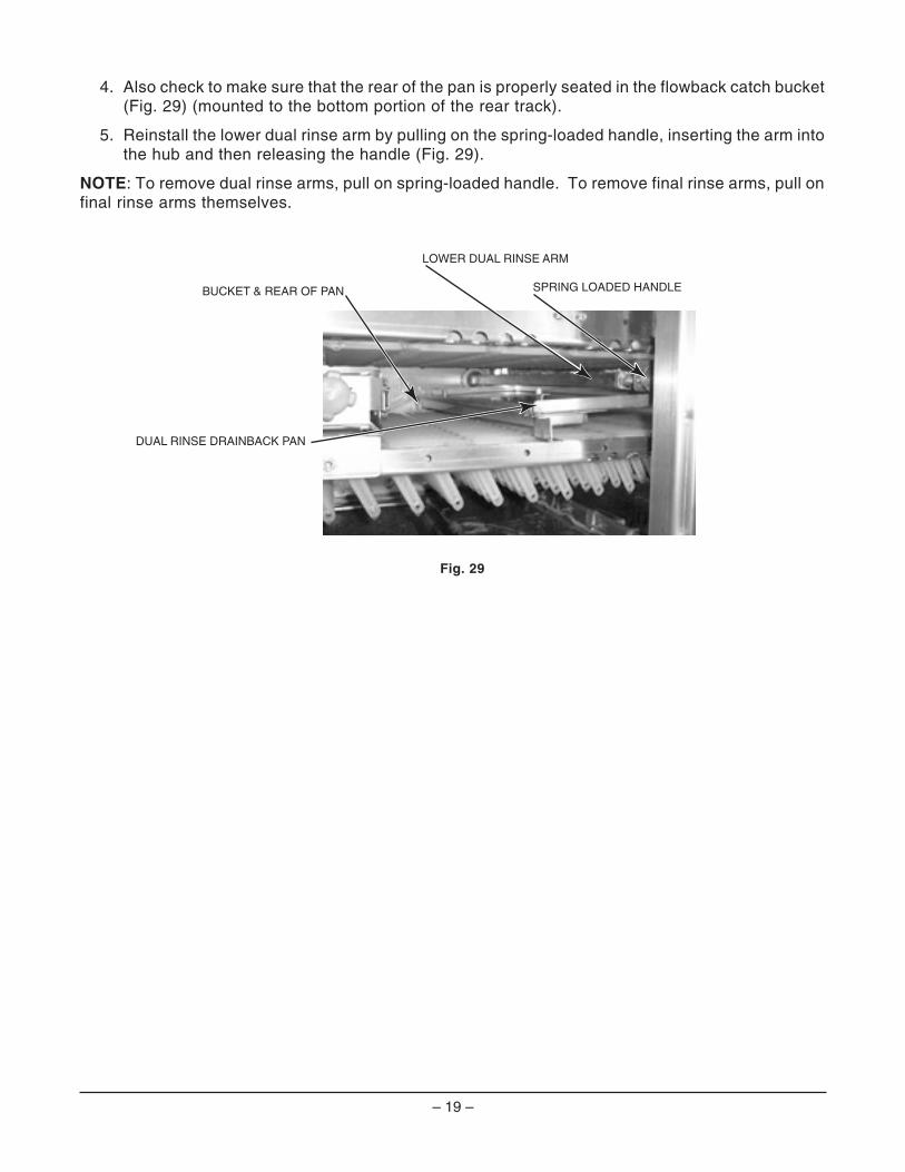
4. Also check to make sure that the rear of the pan is properly seated in the flowback catch bucket(Fig. 29) (mounted to the bottom portion of the rear track).
5. Reinstall the lower dual rinse arm by pulling on the spring-loaded handle, inserting the arm intothe hub and then releasing the handle (Fig. 29).
NOTE: To remove dual rinse arms, pull on spring-loaded handle. To remove final rinse arms, pull onfinal rinse arms themselves.
SPRING LOADED HANDLE
LOWER DUAL RINSE ARM
DUAL RINSE DRAINBACK PAN
BUCKET & REAR OF PAN

– 20 –
Fig. 31 Fig. 32
BLOWER-DRYER ASSEMBLY
This applies to blower-dryers equipped with either electric or steam heat.
When installing the blower-dryer, do not stand, sit or lean on top of dishwasher or airdeflector covers as blower-dryer performance could be compromised.
Remove the louvered blower-dryer cover panels, bothfront and rear (Fig.30).
NOTE: Do not overtighten or put the rubber portionof the vibration isolator in a twist. Secure the bloweroutput to the rivet nuts on the diffuser plenum usingthe four #10-24 screws and lockwashers, provided.
The blower output should be fitted inside the diffuserplenum as the blower and motor assembly is loweredover the six rubber vibration isolator studs (Fig. 31).Install washers, lockwashers and nuts (5/16-18) onthe rubber vibration isolator studs.
Install the black rubber blower fan seal over the blower intake ring (Fig. 32). Position the dryerintake panel assembly inside the blower fan seal. Make sure the black rubber fan seal is outsideboth the blower intake ring and the dryer intake panel assembly. Secure the dryer intake panelassembly to the weldnuts on the blower-dryer frame by assembling the five 1/4 -20 bolts,lockwashers and washers from the inside of the dryer chamber.
Steam-operated blower-dryers have an air filter that mounts over the intake on the blower intakepanel.
Fig. 30
Blower-dryer conduit(s) and cable enter the control box from the rear; specific locations for theseconnections are shown from the front, inside the main control box (Fig. 33). Refer to the wiringdiagram in the main control box.
VIBRATION ISOLATOR
STUD
DIFFUSERPLENUM
DRYER INTAKEBLOWER FAN SEAL
BLOWER INTAKE RING
BLOWER OUTPUT
MOUNT TO 6 VIBRATION ISOLATOR STUDS

– 21 –
Fig. 34 Fig. 35
Extend the blower motor electrical cable from the blower motor junction box to the top rear of the main control box using the strain relief, provided.
Steam blower dryers have an air fi lter that mounts over the blower intake panel and is removable from the discharge end of the blower-dryer.
For the electric blower-dryer, all electric heat wires are routed through 1” conduit from the top inlet cover (Fig. 34). The blower motor cable is routed through the inlet cover with a strain relief fi tting. Both conduit and cable should be connected to the top rear of the main control box using appropriate fi ttings (supplied) (Fig. 33). Refer to the electrical diagram in the main control box.
The steam blower-dryer has the same blower motor cable that is routed through the inlet cover.
Connect blower motor wires labeled 8CON-T1, -T2 and -T3 to contactor 8CON. This applies to blower-dryers with either steam or electric heat.
NOTE: If the blower-dryer is equipped with electric heaters, connect electric heater wires marked 9CON-T1, -T2 and -T3 to contactor 9CON and wires marked 10CON-T1, -T2 and -T3 to contactor 10CON. Also, connect control wires marked 8CON-NO to 8CON Side Switch, 9CON-C1 to contactor 9CON, and 10CON-C3 to contactor 10CON.
Install front and rear covers on the blower dryer (Fig. 35). Fasteners (1/4 -20 bolts, lockwashers and washers) are provided. For additional installation instructions, refer to FORM 35313 for models FT900 or FT900S and to FORM 44091 for models FT900D or FT900SD.
Make sure all hardware is tightened.
Fig. 33
R-L MACHINEBLOWER-DRYER
MOTOR
L-R MACHINEBLOWER-DRYER
MOTOR
PL-52980a
L-R MACHINEBLOWER-DRYER HEATERS
(ELECTRIC ONLY)
R-L MACHINEBLOWER-DRYER HEATERS
(ELECTRIC ONLY)

– 22 –
ELECTRICAL CONNECTION(S)
Electrical and grounding connections must comply with applicable portions of the National Electrical Code (NFPA No.70, latest edition) and / or other local electrical codes.
Disconnect the electrical power to the machine and follow lockout / tagout procedures. There may be multiple circuits. be sure all circuits are disconnected.
With power to all service connections locked out / tagged out, verify that the line and load service connections have been properly tightened.
Refer to the electrical diagram attached to the inside of the control box door. Some machines may require more than one electrical power supply connection. All electrical supply lines to the machine must be disconnected when servicing machine.
CHECKING MOTOR ROTATION (THREE-PHASE MOTORS)
Pumps, conveyor motor and blower-dryer fan motor (when equipped) are all three-phase motors. Before placing the machine into service, check to verify correct rotation by observing motor direction.
If any pump motor does not rotate in the correct direction, check the rotation of the other motors. If they all are rotating backward, disconnect the electrical power supply and interchange any two of the incoming power supply leads. If all motors are not running in the same direction, only change the two incoming wires of the motor(s) that is running backward. Reconnect electrical power, push the START switch and verify that the motors rotate in the proper direction.
NOTE: If the conveyor motor does not rotate in the correct direction, disconnect the electrical power supply and interchange any two of the conveyor motor wires from the Frequency Inverter at terminal 5TB -1, -2 or -3.
SEPARATE ELECTRICAL CONNECTIONS
Separate electrical connections in the main control box may be required for an optional electric blower-dryer heater (when equipped) and for optional electric tank heaters (when equipped) unless equipped with optional circuit breakers. When equipped with an optional electric booster heater, a separate electrical connection at the booster is always required. NOTE: To remove electric booster cover panel, the circuit breaker actuator on the outside of the cover panel must be in the “OFF” position(Fig. 35a). The electric booster water heater may be rated 15 KW or 30 KW. A separate connection is required for a dual-rinse machine unless it is supplied with an electric blower-dryer or with circuit breaker options.
VOLTAGE ADJUSTMENT
This adjustment procedure applies to all FT900 dishwashers equipped with steam heat and rated at 200 to 240 volts, 50 to 60 Hz, 3 phase. All other FT900 dishwasher voltages are preset at the factory and do not require this adjustment procedure.
THIS PROCEDURE MUST BE DONE ONLY BY A QUALIFIED HOBART-TRAINED SERVICE TECHNICIAN.
If the supply voltage to the machine is 224 to 264 volts, no change is necessary. The control circuit transformer [ 1T ] should already be set to operate at 240 volts.
If the supply voltage to the machine is 177 to 224 volts, the control circuit transformer [ 1T ] must be changed to operate at 208 volts.
Fig. 35a

– 23 –
PREWASH DOOR INTERLOCK(S) — SLIDING AND HINGED DOORS
The prewash door interlock(s) is / are prewired from the junction box at the rear of the centersection and is / are shipped with the center section. The door interlock(s) is / are to be installedon the prewash section. Uncoil the prewash door interlock wire(s) and attach the switch body tothe clamp(s) provided at the front of the plenum of the prewash section. Check operation of thedoor interlock and adjust if required. If the center section is shipped in separate sections, connectthe wires to the wash motor, water level control and door interlock as required.
ELECTRICAL CONNECTION — RINSE AID & DETERGENT DISPENSERS
NOTE: This machine must be operated with an automatic detergent feeder, including a visualmeans to verify that detergents are delivered or a visual or audible alarm to signal if detergentsare not available for delivery to the washing system. Please see instructions for electrical andplumbing connections located in this manual and in the feeder equipment manual. Chemicalfeeders are supplied by others.
The machine electrical supply voltage can be used to supply electrical power source for a rinseaid dispenser and/or a detergent dispenser-up to 1.5 amperes each.
Terminal connections, RPS1 and RPS2, are provided for a rinse aid dispenser (ON when the finalrinse is on). Terminal connections, DPS1 and DPS2, are provided for a detergent dispenser (ONwhen the pumps are running). A location for 1/2" conduit is provided at the rear of the control panelfor connection of these devices.
A hole plug is provided in the wash tank for a detergent sensor probe. A plugged hole is providedat the rear of the wash chamber for a liquid detergent dispenser inlet. The access panel can beremoved. Two 1/4" NPT plugs are provided in the copper rinse piping behind the rear access panelfor a rinse aid inlet and rinse line pressure or temperature sensor. Do not use a saddle valve. Thepreferred location for a detergent dispenser and/or a rinse aid dispenser is at the rear of themachine. Route all plumbing and wiring between the rear access panels and chamber wherepossible.
The alternate location for a detergent dispenser is on the cover panel at the front of the machinebetween the prewash and wash section doors. When mounting a detergent dispenser in the frontlocation, remove the cover panel at the front of the machine. Mount brackets for the dispenserand controller on the cover panel so the gravity feed dispenser discharge tube aligns with thechamber hole located behind the cover panel. Make sure the brackets mount the dispenser andcontroller out from the cover panel to allow clearance for the doors to raise freely. Route thedetergent tube to the edge of the strainer in the wash tank. Bring the fresh water line, control andsensor wires up the back of the machine, through the inner top (plenum) and through the backof the cover panel. Make necessary wiring connections through the back of the cover panel to thedispenser and controller.
VENT FAN CONTROL
Machine electrical circuits can be used to switch a vent fan, supplied by others. On all models,the vent fan is ON when the main power switch is on. The two terminal connections for the ventfan control are both labeled VFC and are provided as a switching circuit to control the vent fan.A location for 1/2" conduit is provided at the rear of the control panel for conduit connection for thisapplication.
Power for the vent fan motor is supplied independently.
The maximum rated load for VFC switch connection is 16 amps at 120 to 240 volts, single-phase.

– 24 –
PLUMBING CONNECTIONS Plumbing connections must comply with applicable sanitary, safety and plumbing
codes.Check all water lines, particularly unions. Tighten if necessary.
WATER SUPPLYThe water supply must be within the recommended hardness range of 3 grains or less per gallon. Higher hardness may cause excessive formation of lime scale. Chlorides must not exceed 50 ppm. Recommended water pressure should be 20 to 25 psig (fl owing) at the dishwasher. If the water pressure is higher than 25 psig, a pressure-regulating valve with internal thermal expansion bypass must be supplied (by others) in the water supply line to the dishwasher.
The water pressure regulator must have a relief bypass. Failure to use the proper type of pressure regulator may result in damage to the unit.
Fill
All machines have a single 1” NPT female connection point for the fi ll and/or booster heater. The minimum water temperature for the fi ll connection is 140°F. Machines equipped with the prewash temperature control option require a seperate connection to cold water at a 1” NPT female pipe fi tting at the load end.
Final RinseA water hammer arrestor meeting ASSE-1010 standard or equivalent should be supplied (by others) in the fi nal rinse water supply line at the service connection. The required minimum water temperature for the fi nal rinse is 140°F when an electric or steam booster heater is supplied, the booster heater is plumbed to the fi nal rinse at the factory on FT900D/FT900SD machines. For FT900/FT900S machines, the hose attached to the fi nal rinse piping must be connected to the booster. Machines without booster heater require 180°F water to be connected to the 3/4” NPT female fi tting at the fi nal rinse connection point.
Remove the fi nal rinse arms and purge the fi nal rinse system prior to operation. This will reduce the possibility of clogging the fi nal rinse nozzles. To properly purge the unit, activate the fi nal rinse for 3 to 5 minutes and then reinstall the fi nal rinse arms.
DRAINConnect the drain at the 2” NPT threaded fi tting located at either the unload end or the load end of the machine, as specifi ed on the order.
NOTE: The plug fi tting and the threaded drain fi tting can be interchanged to reverse the drain end of the machine by loosening the stainless steel clamp fi tting. The molded arrows must all point in the same direction on all molded drain T-connectors.
If a grease trap is required by code, the drain should have a fl ow rate of 40 gallons per minute. Do not overtighten the fi ttings.
Line Strainers Line strainers on the machine should be cleaned after installation and within the fi rst week of operation. The line strainers will collect cutting oils and other contaminants. Clogged line strainers will cause restrictions to the fl ow of steam or water and will reduce overall performance of the machine.

– 25 –
STEAM SUPPLY (WHEN EQUIPPED)
Check all steam lines for leaks, particularly unions. Tighten if necessary.
The steam supply must be 15 to 50 psig flowing pressure at the dishwasher. Machines with asteam booster (and steam tank heaters) have a single 11/2" NPT female fitting for connection atthe steam booster at the unload end, underneath. Machines equipped with steam tank heaters,but without a steam booster, have a single 1" NPT female fitting for connection, locatedunderneath the unload end. NOTE: If available steam pressure is less than 15 psi flowing,operational characteristics may be limited because of insufficient delivery of steam. If this occurs,contact Hobart Warewash Technical Support.
Steam Tank Heaters — Condensate Return Lines
The wash tank and power rinse tank may be equipped with steam injector or steam coil types ofheaters. If steam coil types of heaters are used, a condensate return, gravity type, must beconnected for each coil. Bucket-type traps are furnished. The connection points for thecondensate return lines for both coils are 3/4" NPT female pipe fittings. Condensate lines mustnot be plumbed uphill.
Steam Booster Heater — Condensate Return Line and Relief Valves
The connection point for the condensate return line for the steam booster heater is a 3/4" NPTfemale pipe fitting. The steam booster heater is equipped with a steam relief valve that has a1" NPT female pipe fitting that must be piped to an open drain receiver in the floor. The steambooster heater is equipped with a hot-water relief valve that has a 3/4" NPT female pipe fitting thatmust be piped to an open drain receiver in the floor.
The steam booster thermostat (bulb and capillary tube style) is mounted and wired in the maincontrol box. The bulb and capillary tube is shipped with the control box on the center section.During installation, the bulb and capillary tube must be carefully uncoiled and routed to the steambooster and inserted in the booster outlet hot water line through the supplied fitting. Insert thebulb two-thirds of the way into the booster body (refer to tag attached to thermostat, F-44107).
Steam Blower-Dryer (When Equipped)
Steam blower-dryers require a 11/2" connection at the steam coil with 15 to 25 psig maximumflowing pressure on top of the machine. The steam line to the blower-dryer should be fitted witha manual shutoff valve near the connection point suitable for operator convenience. The steamblower-dryer has a condensate return, gravity type, that must be connected from the coil at thebottom of the blower-dryer. Bucket-type traps are furnished. The connection point for thecondensate return line for the coil is a 3/4" NPT female pipe fitting. Condensate lines must not beplumbed uphill.
NOTE: For cleaning convenience, a water tap equipped with 30' of heavy-duty hose and a spraysqueeze valve installed near the machine is recommended.
NOTE: When the blower-dryer is equipped with an optional steam on/off valve, the steam supplyis ON when the machine is ON and OFF when the machine is OFF.
STEAM USAGE / REQUIREMENTS — (POUNDS PER HOUR)
Model Tank Heat Booster Dryer TOTAL TOTAL120°F Incoming Water, Tank Heat Tank Heat, Booster
70°F Rise & Booster & Dryer
FT900, Std Ht 175 125 75 300 375FT900, 6" HTS 175 157 75 332 407FT900S, Std Ht 175 85 75 260 335FT900S, 6" HTS 175 90 75 265 340FT900D, Std Ht & 6" HTS 175 67 75 242 317FT900SD, Std Ht 175 54 75 229 304FT900SD, 6" HTS 175 63 75 238 313

– 26 –
CONVEYOR ASSEMBLY
Prior to installing the conveyor, a quick check should be made to verify that the sprockets are setcorrectly at both the load and unload ends of the machine. The take-up units on both the frontand rear of the load section must be completely retracted towards the load platform so that theconveyor shaft is as square as possible with the machine before attempting this procedure. Then,place a level or combination square across the inside face of the rear sprocket and the insideedge of the rear track (Fig. 36). Both parts should be aligned or set with the sprocket just slightlyto the inside of the track. The inside face of the sprocket should never be set outbound of theinside edge of the track. Once this has been confirmed or properly adjusted, check the insidedimension between the front and rear sprockets; it should be 28 3/16 (+ 1/8 / – 0). If it is not, loosenthe set screw on the front sprocket and slide it forward or backward until the proper dimensionis achieved, then retighten the set screw on the sprocket. When you have completed thisprocedure at both ends of the machine, you will be ready to load the conveyor.
Fig. 36 Fig. 37
LOADING AND JOINING THE CONVEYOR SECTIONS
Each dishwasher is supplied with the correct amount of conveyor. The conveyor sections mustbe connected together.
• All conveyor sections are numbered: ROLL 1, ROLL 2, ROLL 3, ROLL 4, etc.; install them innumerical sequence.
• Raise the loading platform and place a piece of cardboard under, around and above theplatform to protect it from being scratched during conveyor installation.
• Loosen the take-up units (Fig. 37) at the front and rear sides of the load end by looseningthe locknuts and threading the adjusting bolts as far out as possible.
• Remove the chain cover on the unload end and then remove the drive chain from theconveyor gearmotor so that the conveyor sprockets are free to rotate.
• Position the first section of the conveyor in line with the machine at the load end. The flightlinks must point toward the load end of the machine.
• Tie a rope to the first conveyor rod. Feed the rope through the machine following thedesired path of the conveyor with the flight links pointing up. The conveyor rollers mustnot be fed under the tracks.
– 27 –
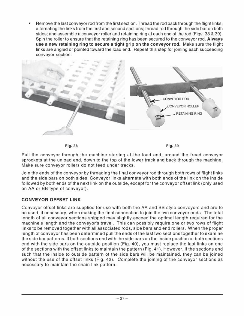
• Remove the last conveyor rod from the first section. Thread the rod back through the flight links,alternating the links from the first and second sections; thread rod through the side bar on bothsides; and assemble a conveyor roller and retaining ring at each end of the rod (Figs. 38 & 39).Spin the roller to ensure that the retaining ring has been secured to the conveyor rod. Alwaysuse a new retaining ring to secure a tight grip on the conveyor rod. Make sure the flightlinks are angled or pointed toward the load end. Repeat this step for joining each succeedingconveyor section.
Fig. 38 Fig. 39
Pull the conveyor through the machine starting at the load end, around the freed conveyorsprockets at the unload end, down to the top of the lower track and back through the machine.Make sure conveyor rollers do not feed under tracks.
Join the ends of the conveyor by threading the final conveyor rod through both rows of flight linksand the side bars on both sides. Conveyor links alternate with both ends of the link on the insidefollowed by both ends of the next link on the outside, except for the conveyor offset link (only usedon AA or BB type of conveyor).
CONVEYOR OFFSET LINK
Conveyor offset links are supplied for use with both the AA and BB style conveyors and are tobe used, if necessary, when making the final connection to join the two conveyor ends. The totallength of all conveyor sections shipped may slightly exceed the optimal length required for themachine's length and the conveyor's travel. This can possibly require one or two rows of flightlinks to be removed together with all associated rods, side bars and end rollers. When the properlength of conveyor has been determined pull the ends of the last two sections together to examinethe side bar patterns. If both sections end with the side bars on the inside position or both sectionsend with the side bars on the outside position (Fig. 40), you must replace the last links on oneof the sections with the offset links to maintain the pattern (Fig. 41). However, if the sections endsuch that the inside to outside pattern of the side bars will be maintained, they can be joinedwithout the use of the offset links (Fig. 42). Complete the joining of the conveyor sections asnecessary to maintain the chain link pattern.
CONVEYOR ROD
CONVEYOR ROLLER
RETAINING RING

– 28 –
Incorrect (Both Side Bars Inside)Fig. 40
Correct with Offset Link (Inside to Outside Maintained)Fig. 41
Correct without Offset LInk (Inside to Outside Pattern Maintained)Fig. 42
Once the conveyor is installed, reinstall the conveyor drive chain to the conveyor gearmotor.
NOTE: The proper length of conveyor, when adjusted, will have the flight links close to orengaging the load fingers at the load platform. It may be necessary to remove one or twoconveyor rods (with rows of flight links) to obtain the desired length.
NOTE: Each time a conveyor roller is installed or replaced, a NEW retaining ring (Fig. 39) mustbe used.

– 29 –
ADJUSTING THE CONVEYOR TAKE-UP UNIT (PREWASH SECTION)
Align the conveyor sprockets or tighten the tension on the conveyor by turning the adjusting bolt on the take-up units (Fig. 43). Alignment can be gauged by centering the large diameter hub of the conveyor rollers on the conveyor tracks.
If the conveyor is tracking straight but travels closer to the front (door side) or toward the rear of the machine, then do the following:
• If tracking closer to the front, tighten the adjusting bolt on the front take-up unit.
• If tracking closer to the rear, tighten the adjusting bolt on the rear take-up unit. If the conveyor is tracking diagonally from one end of the machine to the other, then do the following:
• If tracking diagonally from the front (door side) of the load end toward the rear at the unload end, tighten the adjusting bolt on the front take-up unit.
• If tracking diagonally from the rear on the load end toward the front (door side) on the unload end, tighten the adjusting bolt on the rear take-up unit.
Run the conveyor for 20 minutes. During this time, it may be convenient to perform the booster thermostat calibration described under “Calibrating the Booster Thermostat” in the Miscellaneous section of this manual. After running the conveyor for 20 minutes, stop the conveyor and check the tension. Proper tension is achieved when the conveyor rollers run freely on the bottom track and, by grasping a conveyor rod near the middle, the conveyor can be lifted 1" to 13/4" vertically from the top track on the unload end.
• If additional tension is needed on the conveyor (after it has been centered), tighten both of the take-up units the same amount. After the proper conveyor tension is achieved, tighten the locknuts on the take-up units on both sides (Fig. 43).
With the take-up units properly adjusted, there is a possibility that the sprocket shaft may not be square with the conveyor track. This will not diminish operation provided the conveyor rollers are centered on the track.
Check the set screws in the bearing collars (two each) to make sure that they did not loosen during shipment.
Fig. 43

– 30 –
MISCELLANEOUS
NOTE: Check all bolts and connectors to make sure they are tight.
VENT DUCT
Do not step on top of chambers when installing vent duct.
Fit overhead vent duct (not supplied) inside machine vent opening at the midpoint of thedishwasher and bolt together. The vent fan should provide 1000 cubic feet per minute (cfm) (atstandard air conditions) when the machine is installed with blower-dryer. When the machine isinstalled without blower-dryer, the vent fan should provide 750 cubic feet per minute (cfm) (atstandard conditions). Adjust dampers in plenum at the end of both load and unload sections sothat little vapor escapes from the ends of the machine (Fig. 44). Additional final adjustment canbe made in vent damper adjustment on top of the machine. When the vent damper is adjustedproperly, tighten the nut.
Fig. 44 Fig. 45
PREWASH, WASH AND POWER RINSE ARMS
The upper and lower prewash, wash and power rinse arms must be installed in their correctlocations. To install each of the upper or lower arms, rest the manifold on the support brackets,slide into position and latch the arm in place (Fig. 45).
FINAL RINSE ARMS
Final rinse arms must be in their proper locations — all models. Final rinse arms have non-metallic nozzles.
DUAL RINSE ARMS — MODELS FT900D & FT900SD
Dual rinse arms must be in their proper locations. Dual rinse arms have metallic nozzles.

– 31 –
CURTAINS AND DRAINBACK PANS, MODEL FT900
Curtains and drainback pans must be in their proper places, Fig. 46 . . .
• Hang a short curtain on the unload side of each upper prewash, wash and power rinse arm.
• Hang a long curtain on both sides of every section joint.
• Hang two long curtains at the load end.
• Hang one long curtain at the unload end.
• Place drainback pans as indicated.
Fig. 46
TWO LONG & THREE SHORTDRAINBACK PANS
TWO LONG & THREE SHORTDRAINBACK PANS
FINAL RINSE ARM POWER RINSE ARM WASH ARM PREWASH ARM
FINAL RINSE ARMPOWER RINSE ARMWASH ARMPREWASH ARM
FT900R TO L OPERATION
8' CENTER SECTION
FT900L TO R OPERATION
8' CENTER SECTION
UNLOAD
UNLOAD
LOAD
LOAD
FINAL RINSEDRAINBACK PAN
FINAL RINSEDRAINBACK PAN
FOUR PAIRS OFLONG CURTAINS
THREE SHORT CURTAINS AT UNLOAD SIDEOF UPPER ARMS
THREE SHORT CURTAINS
AT UNLOAD SIDEOF UPPER ARMS
FOUR PAIRS OFLONG CURTAINSONE LONG CURTAIN
AT UNLOAD END
ONE LONG CURTAIN AT UNLOAD END
STRAINER
STRAINER
– 32 –
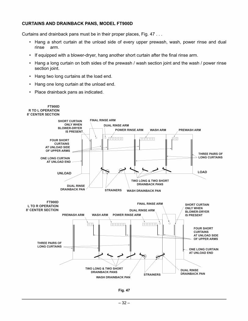
CURTAINS AND DRAINBACK PANS, MODEL FT900D
Curtains and drainback pans must be in their proper places, Fig. 47 . . .
• Hang a short curtain at the unload side of every upper prewash, wash, power rinse and dual rinse arm.
• If equipped with a blower-dryer, hang another short curtain after the fi nal rinse arm.
• Hang a long curtain on both sides of the prewash / wash section joint and the wash / power rinse section joint.
• Hang two long curtains at the load end.
• Hang one long curtain at the unload end.
• Place drainback pans as indicated.
Fig. 47
TWO LONG & TWO SHORTDRAINBACK PANS
WASH DRAINBACK PAN
WASH DRAINBACK PAN
DUAL RINSE ARMPOWER RINSE ARM WASH ARM PREWASH ARM
FT900DR TO L OPERATION
8' CENTER SECTION
UNLOAD LOAD
DUAL RINSEDRAINBACK PAN
FOUR SHORT CURTAINS
AT UNLOAD SIDEOF UPPER ARMS
THREE PAIRS OFLONG CURTAINSONE LONG CURTAIN
AT UNLOAD END
FT900DL TO R OPERATION
8' CENTER SECTION
TWO LONG & TWO SHORTDRAINBACK PANS
FOUR SHORT CURTAINS AT UNLOAD SIDEOF UPPER ARMS
DUAL RINSEDRAINBACK PAN
ONE LONG CURTAIN AT UNLOAD END
THREE PAIRS OFLONG CURTAINS
FINAL RINSE ARMSHORT CURTAIN ONLY WHEN
BLOWER-DRYER IS PRESENT
DUAL RINSE ARMPOWER RINSE ARMWASH ARMPREWASH ARM
FINAL RINSE ARM SHORT CURTAIN ONLY WHEN BLOWER-DRYER IS PRESENT
STRAINERS
STRAINERS
– 33 –
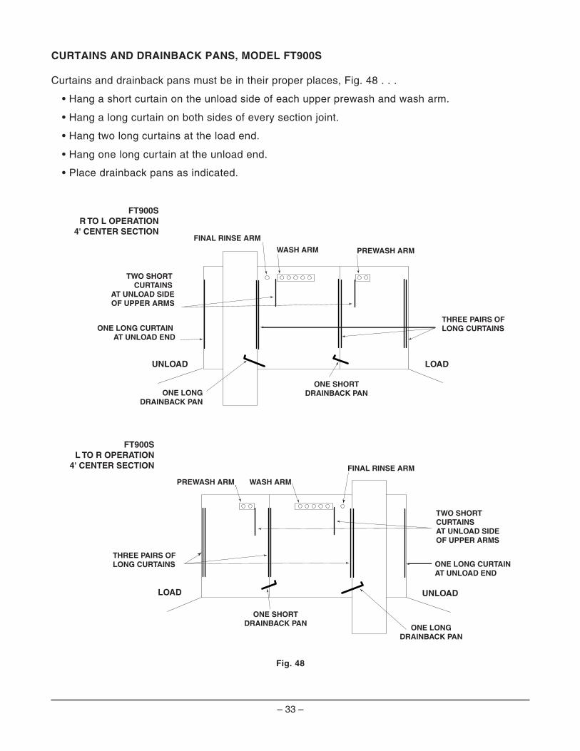
CURTAINS AND DRAINBACK PANS, MODEL FT900S
Curtains and drainback pans must be in their proper places, Fig. 48 . . .
• Hang a short curtain on the unload side of each upper prewash and wash arm.
• Hang a long curtain on both sides of every section joint.
• Hang two long curtains at the load end.
• Hang one long curtain at the unload end.
• Place drainback pans as indicated.
Fig. 48
ONE SHORTDRAINBACK PAN
FINAL RINSE ARM
WASH ARM PREWASH ARM
FT900SR TO L OPERATION
4' CENTER SECTION
UNLOAD LOAD
ONE LONGDRAINBACK PAN
TWO SHORT CURTAINS
AT UNLOAD SIDEOF UPPER ARMS
THREE PAIRS OFLONG CURTAINSONE LONG CURTAIN
AT UNLOAD END
ONE SHORTDRAINBACK PAN
FT900SL TO R OPERATION
4' CENTER SECTION
UNLOADLOAD
ONE LONGDRAINBACK PAN
TWO SHORT CURTAINS AT UNLOAD SIDEOF UPPER ARMS
THREE PAIRS OFLONG CURTAINS ONE LONG CURTAIN
AT UNLOAD END
FINAL RINSE ARM
WASH ARMPREWASH ARM

– 34 –
CURTAINS AND DRAINBACK PANS, MODEL FT900SD
Curtains and drainback pans must be in their proper places, Fig. 49 . . .
• Hang a short curtain at the unload side of every upper prewash, wash and dual rinse arm.
• If equipped with a blower-dryer, hang another short curtain after the final rinse arm.
• Hang a long curtain on both sides of the prewash / wash section joint.
• Hang two long curtains at the load end.
• Hang one long curtain at the unload end.
• Place drainback pans as indicated.
Fig. 49
FT900SDR TO L OPERATION
4' CENTER SECTION
UNLOAD LOAD
DUAL RINSEDRAINBACK PAN
THREE SHORT CURTAINS AT UNLOAD SIDEOF UPPER ARMS
ONE LONG CURTAIN AT UNLOAD END
UNLOADLOAD
DUAL RINSEDRAINBACK PAN
ONE LONG CURONE LONG CURTAIN AIN AT UNLOAD END UNLOAD END
FT900SDL TO R OPERATION
4' CENTER SECTION
THREE SHORT CURTAINS AT UNLOAD SIDEOF UPPER ARMS
ONE SHORTDRAINBACK PAN
ONE SHORTDRAINBACK PAN
FINAL RINSE ARM
WASH ARM PREWASH ARM
FINAL RINSE ARM
WASH ARMPREWASH ARM
DUAL RINSE ARM
DUAL RINSE ARM
TWO PAIRS OFLONG CURTAINS
TWO PAIRS OFLONG CURTAINS
SHORT CURTAIN ONLY WHEN
BLOWER-DRYER IS PRESENT
SHORT CURTAIN ONLY WHEN BLOWER-DRYER IS PRESENT
STRAINER
STRAINER

– 35 –
CONVEYOR GEARMOTOR
The conveyor gearmotor is shipped with oil at the proper level in the speed reducer.
Lubricants are available from your local Hobart Service Offi ce.
LOWER TRIM PANELS (FRONT)
Hang lower front trim panels from two (or more) hanger brackets under the front tank support rail. Slots in bottom of panels should be inserted into panel bracket retainers. Lower panel bracket retainers may project from the lower rails of the machine or may be attached to an adjacent panel. Each panel must be located in its proper position.
When installing lower trim panels, butt each panel end to end and then adjust the end wrap panel so there is approximately 1/16” clearance between it and the adjacent panel. This clearance, spread over the entire length of the machine, will provide optimum appearance (Fig. 50).
REAR PANELS
Hang rear panels from two upper hanger brackets at the top (Fig. 51) and insert slots in bottom of panels into panel bracket retainers. Lower panel bracket retainers may project from the lower rails of the machine or may be attached to an adjacent panel. Each panel must be located in its proper position. Each rear panel and chamber is numbered to identify position.
Fig. 50 Fig. 51

– 36 –
CALIBRATING THE ELECTRIC BOOSTER THERMOSTAT
NOTE: This procedure only needs to be followed once during initial setup.
NOTE: This procedure may be followed during the 20 minute period in the “Adjusting the Conveyor Take-up Unit (Prewash Section)” procedure.
NOTE: This procedure should only be followed if both the booster can be powered on and the booster has hot water of at least 105F fl owing into it.
For the internal Hobart booster (15kW or 30kW), the controlling thermostat needs to be calibrated to the conditions at the customer’s site. The calibration is automatic while the machine is running.
To begin calibration, ensure the booster’s circuit breaker is set to the “ON” position and power is present at ##CON. Start the conveyor running. Block the upper photo detector for at least 20 minutes.
NOTE: Do not put ware or any other item on the conveyor during the procedure. This may cause the dish limit arm to trip and stop the conveyor movement. If the conveyor stops for any reason during the 20 minute calibration period, the procedure should be rerun from the beginning to ensure proper calibration.
After 20 minutes, unblock the photo detector. When the fi nal rinse output turns off and the display shows “---” for the fi nal rinse temperature, stop the conveyor. Power off the machine by pressing the POWER button on the keypad. This saves the calibration data and completes the automatic calibration.
– 37 –
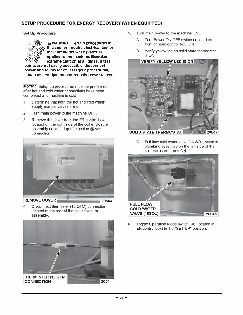
SETUP PROCEDURE FOR ENERGY RECOVERY (WHEN EQUIPPED)
Set Up Procedure
Setup up procedures must be preformedafter hot and cold water connections have beencompleted and machine is cold.
1. Determine that both the hot and cold watersupply manual valves are on.
2. Turn main power to the machine OFF.
3. Remove the cover from the ER control boxlocated on the right side of the coil enclosureassembly (located top of machine @ ventconnection).
4. Disconnect thermister (10 QTM) connectionlocated at the rear of the coil enclosureassembly.
5. Turn main power to the machine ON.
A. Turn Power ON/OFF switch (located onfront of main control box) ON.
B. Verify yellow led on solid state thermostatis ON.
C. Full flow cold water valve (10 SOL, valve inplumbing assembly on the left side of thecoil enclosure) turns ON.
6. Toggle Operation Mode switch (3S, located inER control box) to the "SET-UP" position.

– 38 –
A. Final Rinse valve (3 SOL) turns ON.
B. Adjust pressure regulator on the cold waterplumbing assembly (under load/pre-washsection) until final rinse pressure gaugereads 22 ± 2 PSI.
7. After the cold water pressure is established,reconnect the thermister (10 QTM) connection.
A. Verify red light on solid state thermostat isON.
B. Verify full flow cold water valve (10 SOL)turns OFF.
C. Hot water valve (12 SOL located undercenter/wash section) turns ON.
8. Adjust the pressure regulator in the hot waterplumbing assembly (located between Wash &Power Rinse sections for FT900/FT900D orbetween the Wash & Unload sections forFT900S/FT900SD) until final rinse pressuregauge reading matches the value set for thecold water supply 22 ± 2 PSI.
9. Toggle Operation Mode switch (3S) to the"NORMAL" position, Figure 4.
A. Final Rinse Valve (3SOL) turns OFF.
10. Turn power ON/OFF switch located on front ofmain control box OFF.
11. Turn main power to machine OFF.
12. Replace control box cover, Figure 1.
13. Turn main power to the machine ON; machineis now ready for normal operation.

– 39 –
SERVICEIf service is needed on this machine, contact your local Hobart Service Offi ce.

– 40 –FORM 44093 Rev. A (Dec. 2010) PRINTED IN U.S.A.
NOTES