FSDP & FSMP - 09/10 SSDP - 10/12 Drive Steer Axles * XSDP10AX.fm 5 Maintenance Manual XSDP-09/10/12...
51
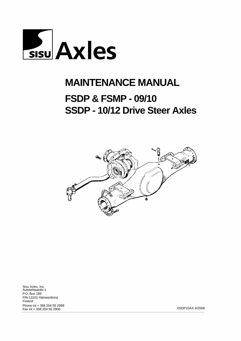
Sisu Axles, Inc. Autotehtaantie 1 P.O. Box 189 FIN-13101 Hämeenlinna Phone int + 358 204 55 2999 Fax int + 358 204 55 2900 Finland XSDP10AX 4/2008 MAINTENANCE MANUAL FSDP & FSMP - 09/10 SSDP - 10/12 Drive Steer Axles
Transcript of FSDP & FSMP - 09/10 SSDP - 10/12 Drive Steer Axles * XSDP10AX.fm 5 Maintenance Manual XSDP-09/10/12...
Sisu Axles, Inc.Autotehtaantie 1P.O. Box 189FIN-13101 Hämeenlinna
Phone int + 358 204 55 299Fax int + 358 204 55 2900
Finland
MAINTENANCE MANUAL
FSDP & FSMP - 09/10SSDP - 10/12 Drive Steer Axles
9XSDP10AX 4/2008

List of contents ......................................................................................... PageDesign and function.........................................................................................5
XSDP axle design ......................................................................................5These axles are used as follows: ...................................................................5Description of the service and repair works ....................................................7
Planetary hubs - disassembly ....................................................................7Disassembly - steering knuckles ..............................................................14Assembly - steering knuckles ...................................................................21Planetary hubs - assembly .......................................................................28
Toe-in adjustment .........................................................................................34Wheel hub - oil level check ...........................................................................35Oil recommendation .....................................................................................36Greasing .......................................................................................................36Brakes ..........................................................................................................39
Servicing ..................................................................................................39Lubrication ................................................................................................39Inspection .................................................................................................39Adjustment with manual adjusters ...........................................................40Adjustment with automatic aqdjusters ......................................................41Brake inspection (in use).......................................................................... 42S-Cam shaft adjustment in front axles - Bellewille spring adjustment ......42Brake drum ...............................................................................................43
Brake drum machining .........................................................................44Brake linings .............................................................................................44
Riveting brake linings............................................................................45Brake vibrations .......................................................................................46
Attaching the wheel ......................................................................................47Brake maintenance - Dismatling ...................................................................47Removing the brake shoes ...........................................................................47Attaching the brake shoes ............................................................................47Technical data ..............................................................................................49Special tools .................................................................................................51
NOTE ! This Manual is intended for use by experienced mechanics using safeprocedures in properly equipped shops.Safety precautions should always be followed such as wearing safety glasses,using adequate lifting aids, and using tools and equipment in good condition.Sisu Axles, Inc., its agents, associates or representatives are not responsible fordamage or injury occurring while working on their components.
11/99 * XSDP10AXTOC.fm 3
4 11/99 * XSDP10AXTOC.fm
Maintenance Manual XSDP-09/10/12 Axles
1 DESIGN AND FUNCTION
1.1 XSDP AXLE DESIGN
The axle primary gearing is composed of a pair of bevel wheels located among the drive gear between the axles.
Power from the drive gear is transmitted by an axle shaft equipped with two universal joints to the wheel hub, which has a five-planet type planetary gear to act as a secondary gearing.
The sun wheel connected to the end of the axle shaft rotates the planet wheel carrier by means of the planet wheels, which are connected to the wheel hub. The ring gear is locked to the swivel axle. The drive gear and dif-ferential, gear, together with bearings, are lubricated with oil from the drive gear housing. The hubs of the wheels have their own separate oil reservoirs to lubricate the planetary gears.
These axles are used as follows:• Low ratio axle in industrial applications : SSDP-10/12
• High ratio axle in automotive applications: FSDP-09/10
Drive gear is in separate manual.
WDB brakes are in separate manual.
11/99 * XSDP10AX.fm 5
Maintenance Manual XSDP-09/10/12 Axles
6 11/99 * XSDP10AX.fm
Maintenance Manual XSDP-09/10/12 Axles
2 DESCRIPTION OF THE SERVICE AND REPAIR WORKS
2.1 PLANETARY HUBS - DISASSEMBLY
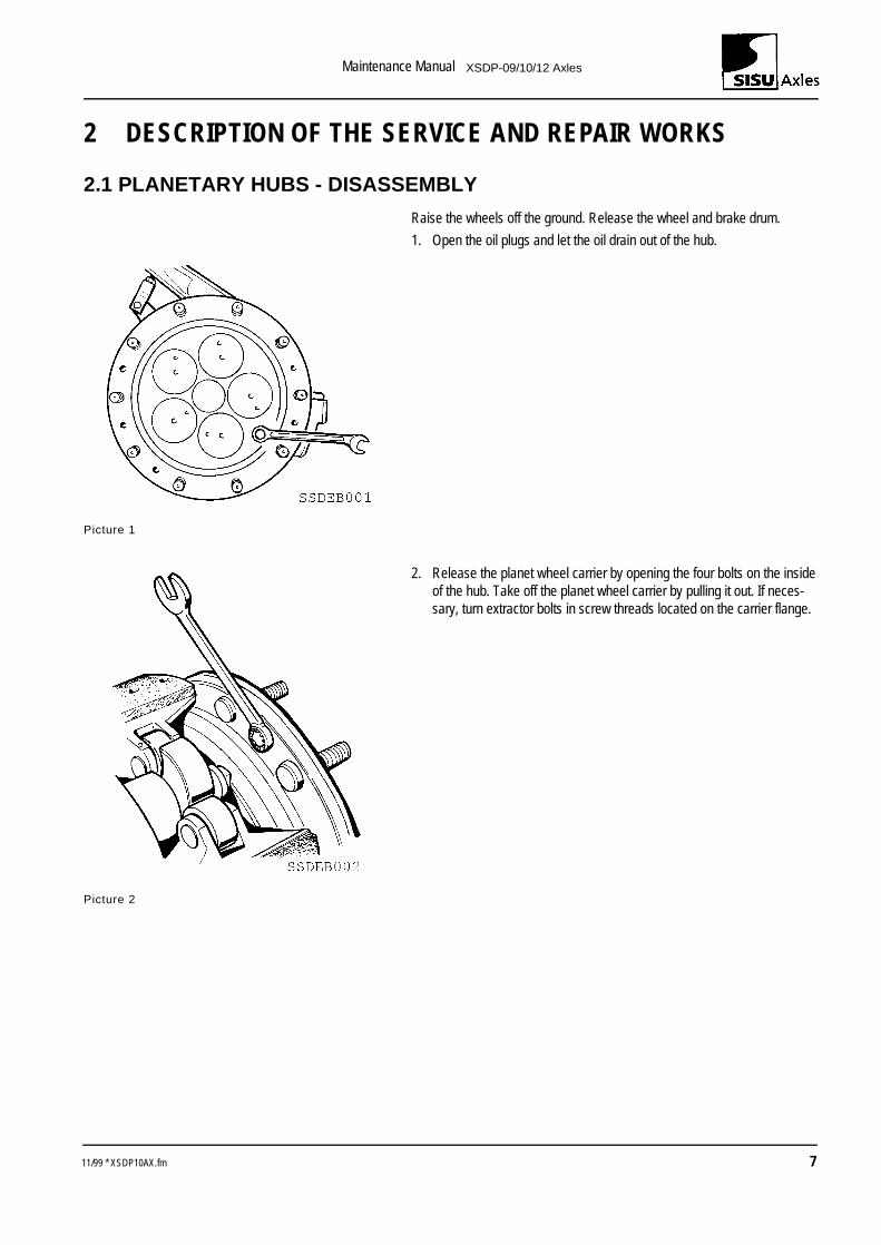
Raise the wheels off the ground. Release the wheel and brake drum.
1. Open the oil plugs and let the oil drain out of the hub.
Picture 1
2. Release the planet wheel carrier by opening the four bolts on the inside of the hub. Take off the planet wheel carrier by pulling it out. If neces-sary, turn extractor bolts in screw threads located on the carrier flange.
Picture 2
11/99 * XSDP10AX.fm 7
Maintenance Manual XSDP-09/10/12 Axles
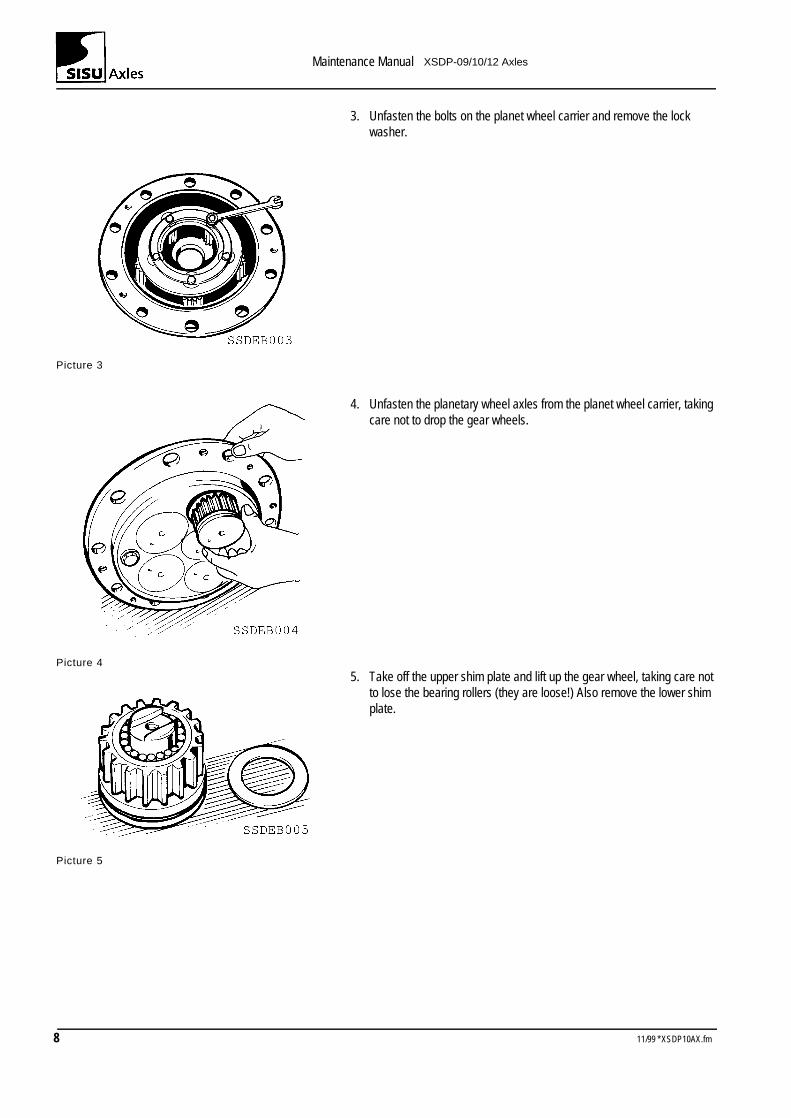
3. Unfasten the bolts on the planet wheel carrier and remove the lock washer.
Picture 3
4. Unfasten the planetary wheel axles from the planet wheel carrier, taking care not to drop the gear wheels.
Picture 4 5. Take off the upper shim plate and lift up the gear wheel, taking care not
to lose the bearing rollers (they are loose!) Also remove the lower shim plate.
Picture 5
8 11/99 * XSDP10AX.fm
Maintenance Manual XSDP-09/10/12 Axles
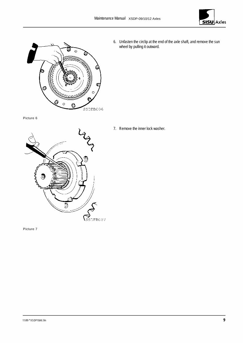
6. Unfasten the circlip at the end of the axle shaft, and remove the sun wheel by pulling it outward.
Picture 6
7. Remove the inner lock washer.
Picture 7
11/99 * XSDP10AX.fm 9
Maintenance Manual XSDP-09/10/12 Axles
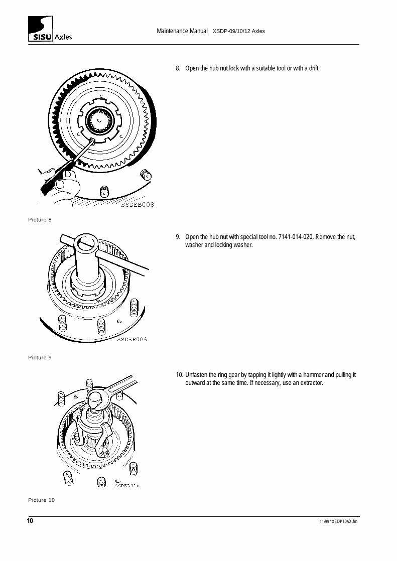
8. Open the hub nut lock with a suitable tool or with a drift.
Picture 8
9. Open the hub nut with special tool no. 7141-014-020. Remove the nut, washer and locking washer.
Picture 9
10. Unfasten the ring gear by tapping it lightly with a hammer and pulling it outward at the same time. If necessary, use an extractor.
Picture 10
10 11/99 * XSDP10AX.fm
Maintenance Manual XSDP-09/10/12 Axles
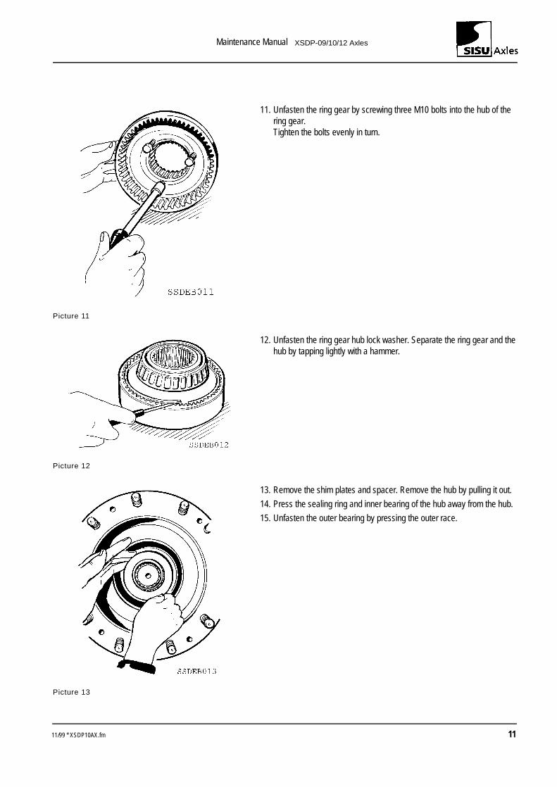
11. Unfasten the ring gear by screwing three M10 bolts into the hub of the ring gear.Tighten the bolts evenly in turn.
Picture 11
12. Unfasten the ring gear hub lock washer. Separate the ring gear and the hub by tapping lightly with a hammer.
Picture 12
13. Remove the shim plates and spacer. Remove the hub by pulling it out.
14. Press the sealing ring and inner bearing of the hub away from the hub.
15. Unfasten the outer bearing by pressing the outer race.
Picture 13
11/99 * XSDP10AX.fm 11
Maintenance Manual XSDP-09/10/12 Axles
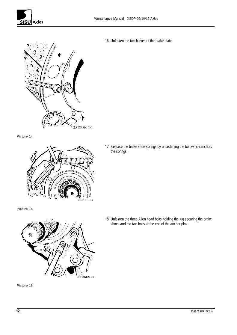
16. Unfasten the two halves of the brake plate.
Picture 14
17. Release the brake shoe springs by unfastening the bolt which anchors the springs.
Picture 15
18. Unfasten the three Allen head bolts holding the lug securing the brake shoes and the two bolts at the end of the anchor pins.
Picture 16
12 11/99 * XSDP10AX.fm
Maintenance Manual XSDP-09/10/12 Axles
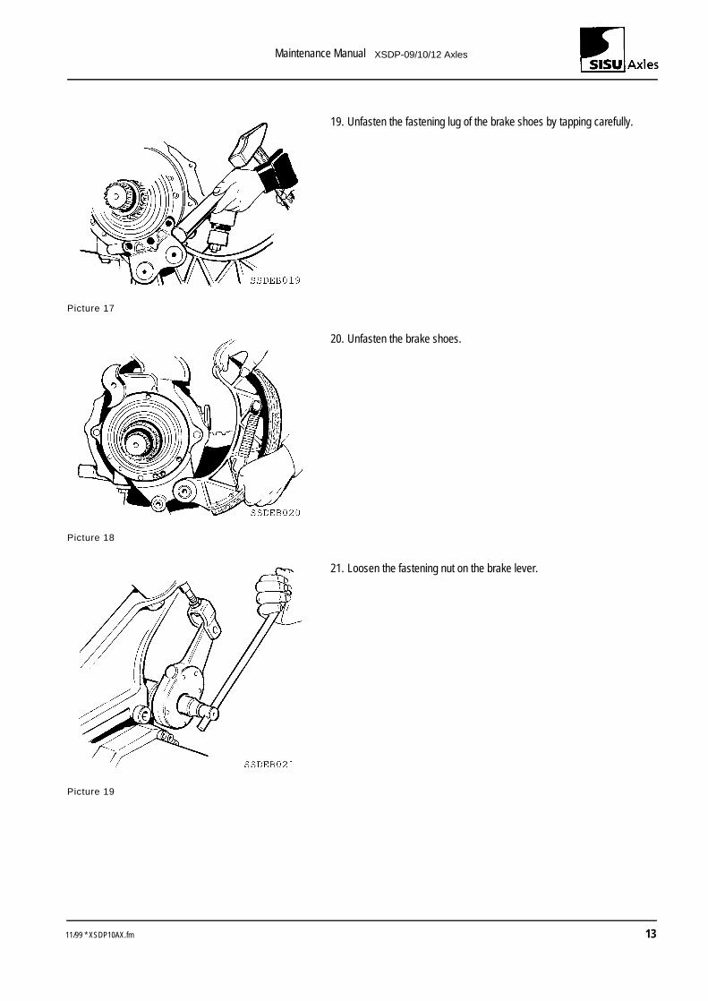
19. Unfasten the fastening lug of the brake shoes by tapping carefully.
Picture 17
20. Unfasten the brake shoes.
Picture 18
21. Loosen the fastening nut on the brake lever.
Picture 19
11/99 * XSDP10AX.fm 13
Maintenance Manual XSDP-09/10/12 Axles
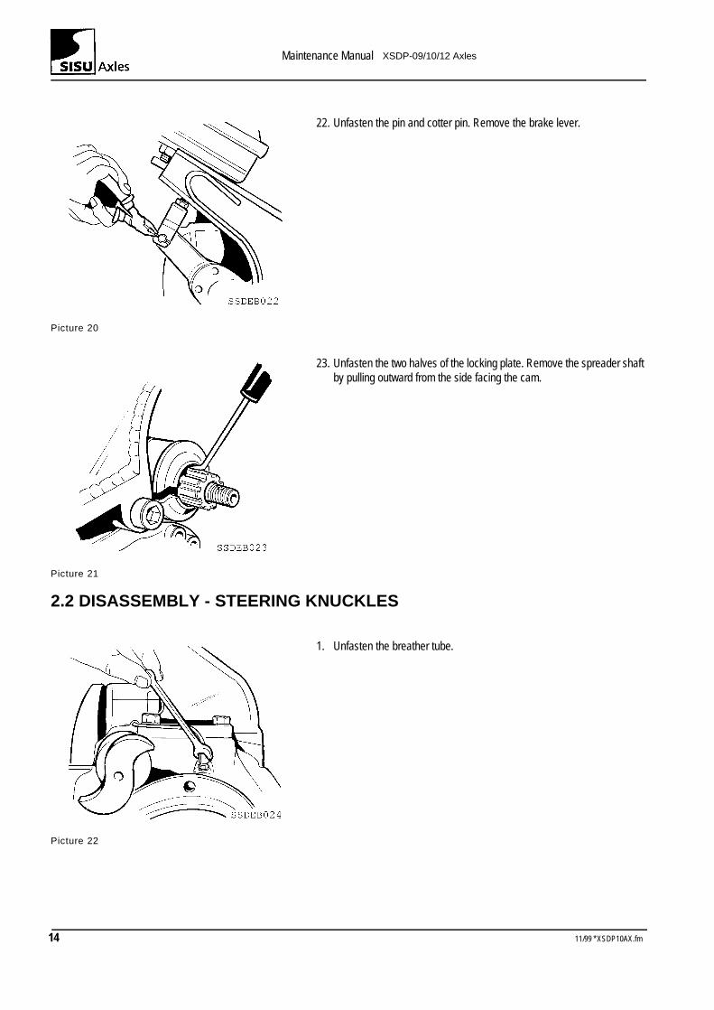
22. Unfasten the pin and cotter pin. Remove the brake lever.
Picture 20
23. Unfasten the two halves of the locking plate. Remove the spreader shaft by pulling outward from the side facing the cam.
Picture 21
2.2 DISASSEMBLY - STEERING KNUCKLES
1. Unfasten the breather tube.
Picture 22
14 11/99 * XSDP10AX.fm
Maintenance Manual XSDP-09/10/12 Axles
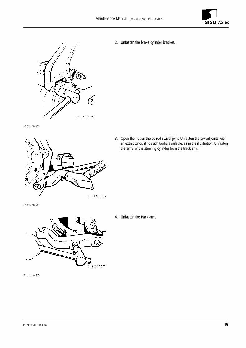
2. Unfasten the brake cylinder bracket.
Picture 23
3. Open the nut on the tie rod swivel joint. Unfasten the swivel joints with an extractor or, if no such tool is available, as in the illustration. Unfasten the arms of the steering cylinder from the track arm.
Picture 24
4. Unfasten the track arm.
Picture 25
11/99 * XSDP10AX.fm 15
Maintenance Manual XSDP-09/10/12 Axles
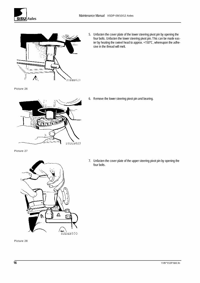
5. Unfasten the cover plate of the lower steering pivot pin by opening the four bolts. Unfasten the lower steering pivot pin. This can be made eas-ier by heating the swivel head to approx. +150°C, whereupon the adhe-sive in the thread will melt.
Picture 26
6. Remove the lower steering pivot pin and bearing.
Picture 27
7. Unfasten the cover plate of the upper steering pivot pin by opening the four bolts.
Picture 28
16 11/99 * XSDP10AX.fm
Maintenance Manual XSDP-09/10/12 Axles
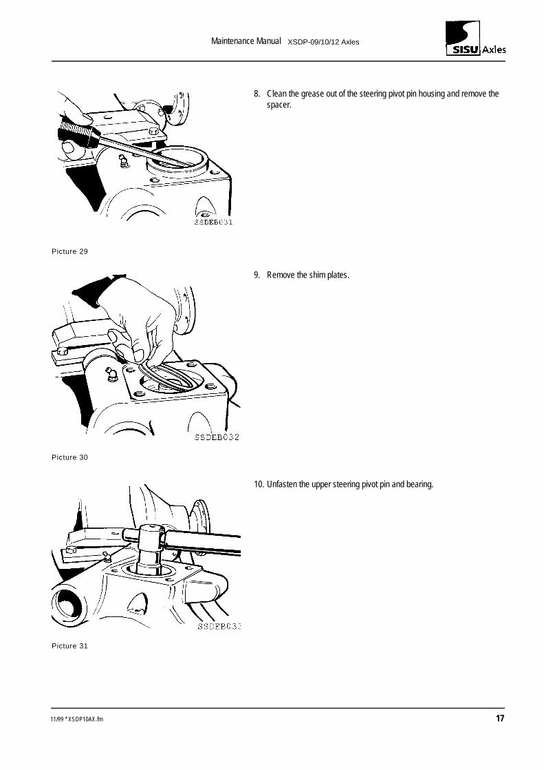
8. Clean the grease out of the steering pivot pin housing and remove the spacer.
Picture 29
9. Remove the shim plates.
Picture 30
10. Unfasten the upper steering pivot pin and bearing.
Picture 31
11/99 * XSDP10AX.fm 17
Maintenance Manual XSDP-09/10/12 Axles
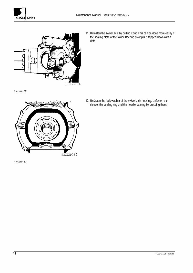
11. Unfasten the swivel axle by pulling it out. This can be done more easily if the sealing plate of the lower steering pivot pin is tapped down with a drift.
Picture 32
12. Unfasten the lock washer of the swivel axle housing. Unfasten the sleeve, the sealing ring and the needle bearing by pressing them.
Picture 33
18 11/99 * XSDP10AX.fm
Maintenance Manual XSDP-09/10/12 Axles
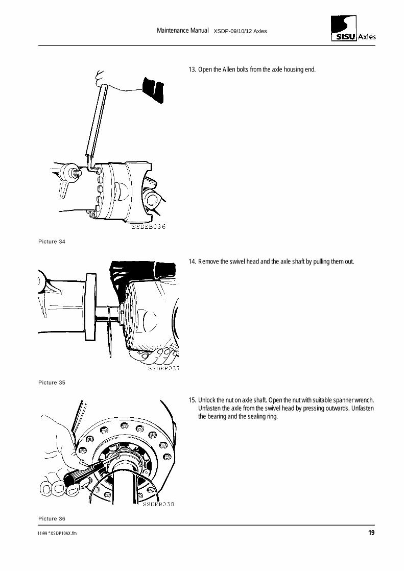
13. Open the Allen bolts from the axle housing end.
Picture 34
14. Remove the swivel head and the axle shaft by pulling them out.
Picture 35
15. Unlock the nut on axle shaft. Open the nut with suitable spanner wrench. Unfasten the axle from the swivel head by pressing outwards. Unfasten the bearing and the sealing ring.
Picture 36
11/99 * XSDP10AX.fm 19
Maintenance Manual XSDP-09/10/12 Axles
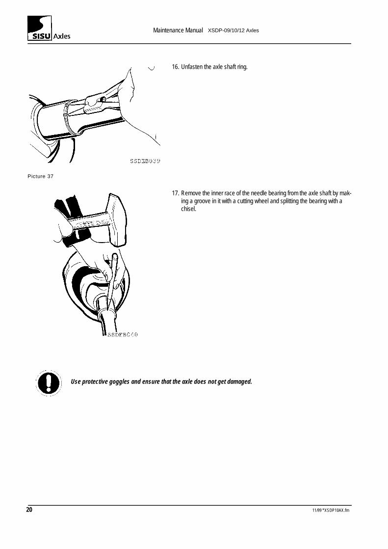
16. Unfasten the axle shaft ring.
Picture 37
17. Remove the inner race of the needle bearing from the axle shaft by mak-ing a groove in it with a cutting wheel and splitting the bearing with a chisel.
Use protective goggles and ensure that the axle does not get damaged.
20 11/99 * XSDP10AX.fm
Maintenance Manual XSDP-09/10/12 Axles
2.3 ASSEMBLY- STEERING KNUCKLES
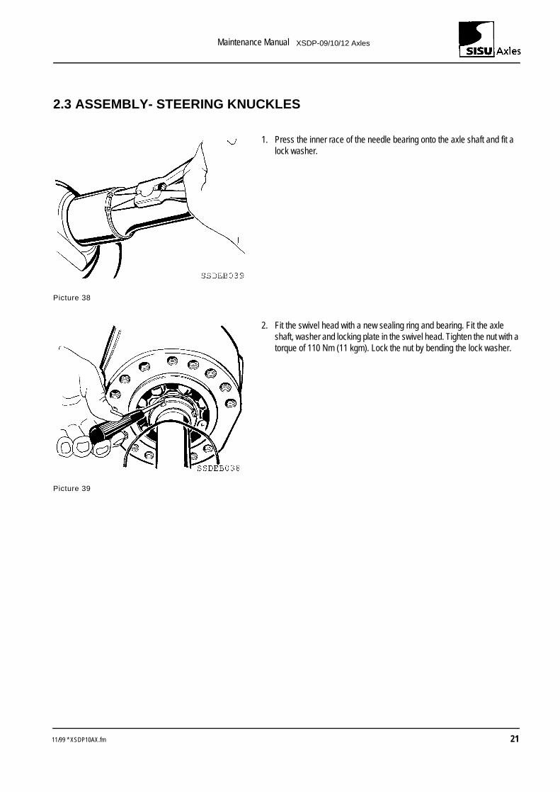
1. Press the inner race of the needle bearing onto the axle shaft and fit a lock washer.
Picture 38
2. Fit the swivel head with a new sealing ring and bearing. Fit the axle shaft, washer and locking plate in the swivel head. Tighten the nut with a torque of 110 Nm (11 kgm). Lock the nut by bending the lock washer.
Picture 39
11/99 * XSDP10AX.fm 21
Maintenance Manual XSDP-09/10/12 Axles
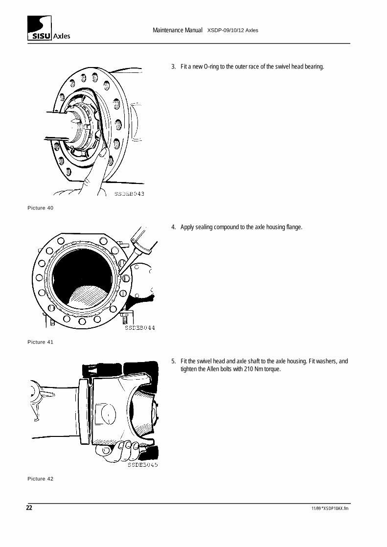
3. Fit a new O-ring to the outer race of the swivel head bearing.
Picture 40
4. Apply sealing compound to the axle housing flange.
Picture 41
5. Fit the swivel head and axle shaft to the axle housing. Fit washers, and tighten the Allen bolts with 210 Nm torque.
Picture 42
22 11/99 * XSDP10AX.fm
Maintenance Manual XSDP-09/10/12 Axles
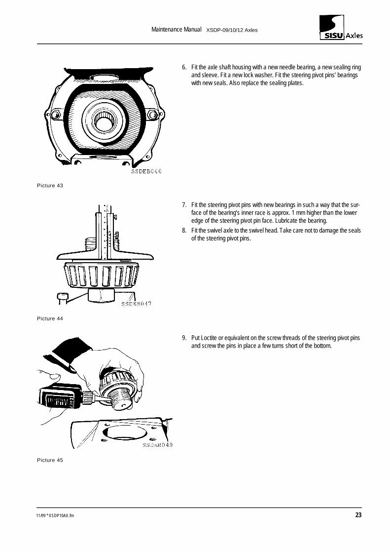
6. Fit the axle shaft housing with a new needle bearing, a new sealing ring and sleeve. Fit a new lock washer. Fit the steering pivot pins’ bearings with new seals. Also replace the sealing plates.
Picture 43
7. Fit the steering pivot pins with new bearings in such a way that the sur-face of the bearing’s inner race is approx. 1 mm higher than the lower edge of the steering pivot pin face. Lubricate the bearing.
8. Fit the swivel axle to the swivel head. Take care not to damage the seals of the steering pivot pins.
Picture 44
9. Put Loctite or equivalent on the screw threads of the steering pivot pins and screw the pins in place a few turns short of the bottom.
Picture 45
11/99 * XSDP10AX.fm 23
Maintenance Manual XSDP-09/10/12 Axles
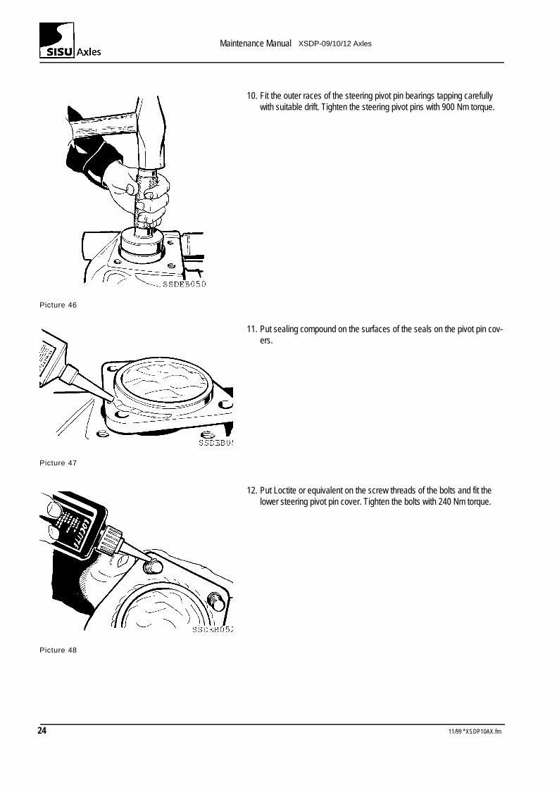
10. Fit the outer races of the steering pivot pin bearings tapping carefully with suitable drift. Tighten the steering pivot pins with 900 Nm torque.
Picture 46
11. Put sealing compound on the surfaces of the seals on the pivot pin cov-ers.
Picture 47
12. Put Loctite or equivalent on the screw threads of the bolts and fit the lower steering pivot pin cover. Tighten the bolts with 240 Nm torque.
Picture 48
24 11/99 * XSDP10AX.fm
Maintenance Manual XSDP-09/10/12 Axles
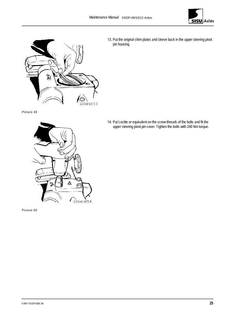
13. Put the original shim plates and sleeve back in the upper steering pivot pin housing.
Picture 49
14. Put Loctite or equivalent on the screw threads of the bolts and fit the upper steering pivot pin cover. Tighten the bolts with 240 Nm torque.
Picture 50
11/99 * XSDP10AX.fm 25
Maintenance Manual XSDP-09/10/12 Axles
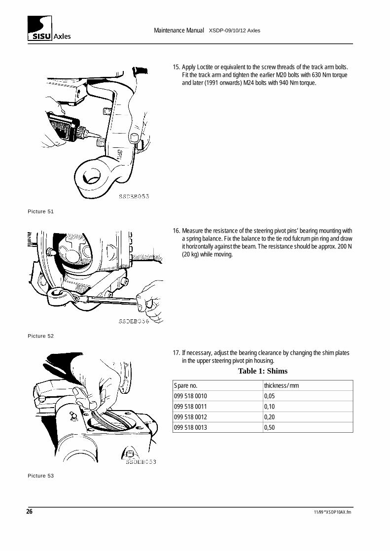
15. Apply Loctite or equivalent to the screw threads of the track arm bolts. Fit the track arm and tighten the earlier M20 bolts with 630 Nm torque and later (1991 onwards) M24 bolts with 940 Nm torque.
Picture 51
16. Measure the resistance of the steering pivot pins’ bearing mounting with a spring balance. Fix the balance to the tie rod fulcrum pin ring and draw it horizontally against the beam. The resistance should be approx. 200 N (20 kg) while moving.
Picture 52
17. If necessary, adjust the bearing clearance by changing the shim plates in the upper steering pivot pin housing.
Table 1: Shims
Picture 53
Spare no. thickness/ mm
099 518 0010 0,05
099 518 0011 0,10
099 518 0012 0,20
099 518 0013 0,50
26 11/99 * XSDP10AX.fm
Maintenance Manual XSDP-09/10/12 Axles
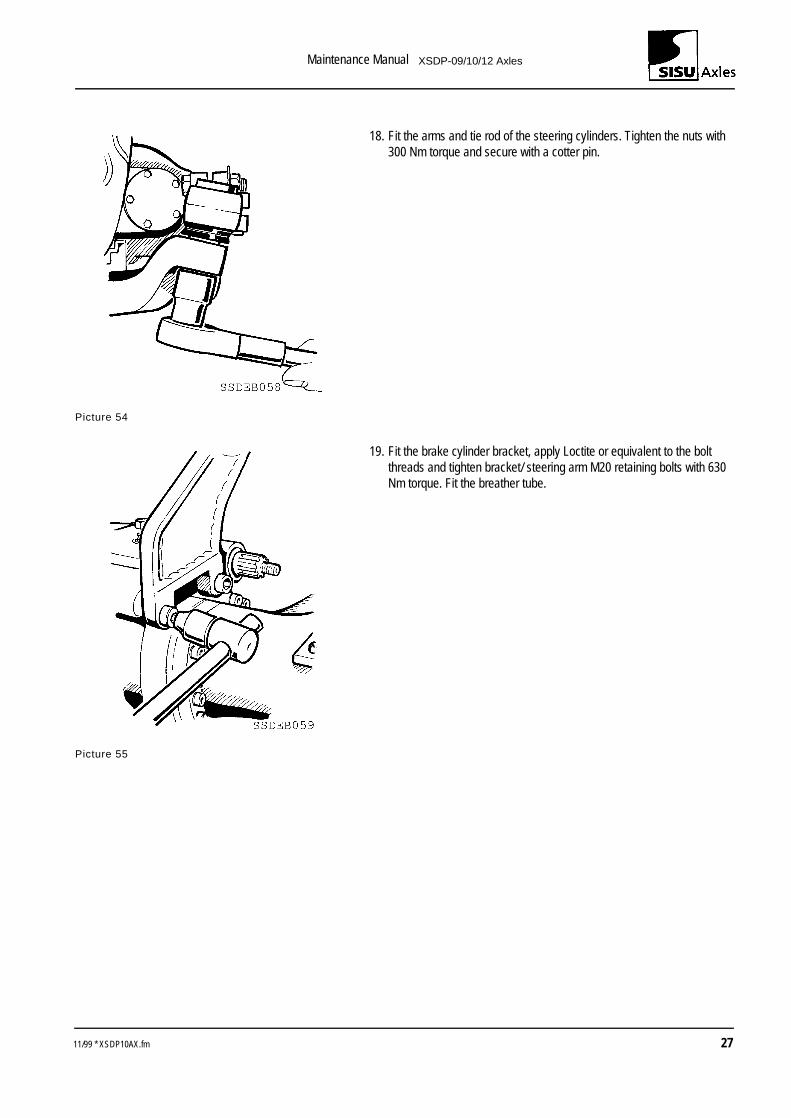
18. Fit the arms and tie rod of the steering cylinders. Tighten the nuts with 300 Nm torque and secure with a cotter pin.
Picture 54
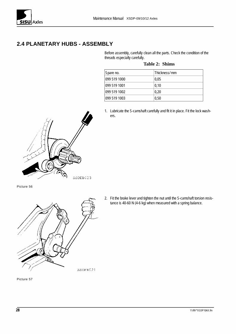
19. Fit the brake cylinder bracket, apply Loctite or equivalent to the bolt threads and tighten bracket/ steering arm M20 retaining bolts with 630 Nm torque. Fit the breather tube.
Picture 55
11/99 * XSDP10AX.fm 27
Maintenance Manual XSDP-09/10/12 Axles
2.4 PLANETARY HUBS - ASSEMBLY
Before assembly, carefully clean all the parts. Check the condition of the threads especially carefully.
Table 2: Shims
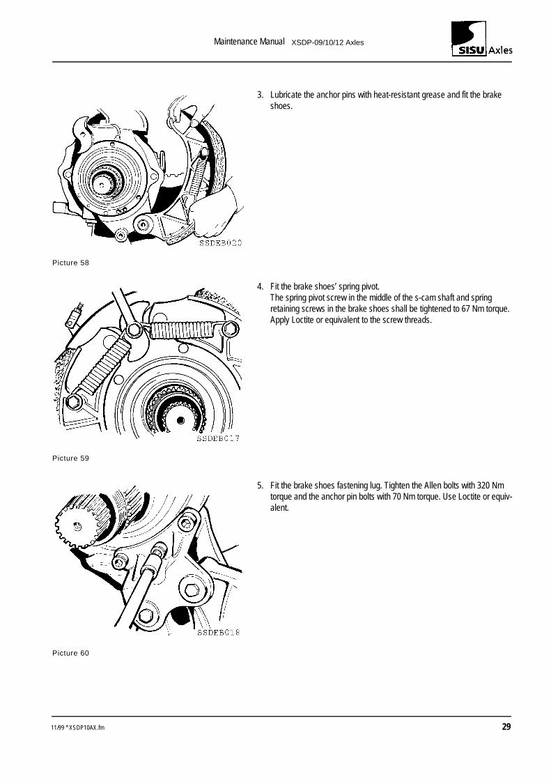
1. Lubricate the S-camshaft carefully and fit it in place. Fit the lock wash-ers.
Picture 56
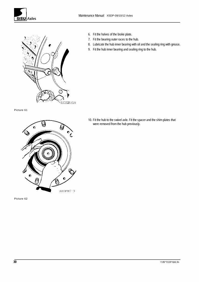
2. Fit the brake lever and tighten the nut until the S-camshaft torsion resis-tance is 40-60 N (4-6 kg) when measured with a spring balance.
Picture 57
Spare no. Thickness/ mm
099 519 1000 0,05
099 519 1001 0,10
099 519 1002 0,20
099 519 1003 0,50
28 11/99 * XSDP10AX.fm
Maintenance Manual XSDP-09/10/12 Axles
3. Lubricate the anchor pins with heat-resistant grease and fit the brake shoes.
Picture 58
4. Fit the brake shoes’ spring pivot.The spring pivot screw in the middle of the s-cam shaft and spring retaining screws in the brake shoes shall be tightened to 67 Nm torque.Apply Loctite or equivalent to the screw threads.
Picture 59
5. Fit the brake shoes fastening lug. Tighten the Allen bolts with 320 Nm torque and the anchor pin bolts with 70 Nm torque. Use Loctite or equiv-alent.
Picture 60
11/99 * XSDP10AX.fm 29
Maintenance Manual XSDP-09/10/12 Axles
6. Fit the halves of the brake plate.
7. Fit the bearing outer races to the hub.
8. Lubricate the hub inner bearing with oil and the sealing ring with grease.
9. Fit the hub inner bearing and sealing ring to the hub.
Picture 61
10. Fit the hub to the swivel axle. Fit the spacer and the shim plates that were removed from the hub previously.
Picture 62
30 11/99 * XSDP10AX.fm
Maintenance Manual XSDP-09/10/12 Axles
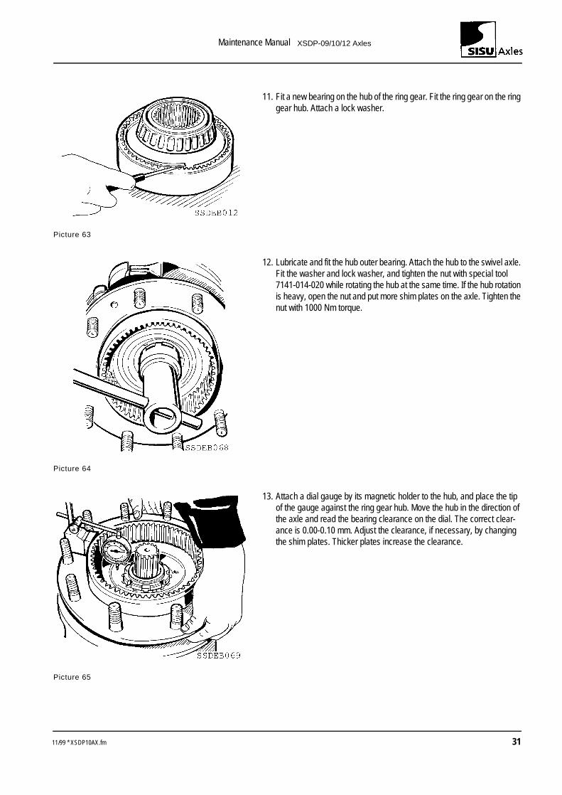
11. Fit a new bearing on the hub of the ring gear. Fit the ring gear on the ring gear hub. Attach a lock washer.
Picture 63
12. Lubricate and fit the hub outer bearing. Attach the hub to the swivel axle. Fit the washer and lock washer, and tighten the nut with special tool 7141-014-020 while rotating the hub at the same time. If the hub rotation is heavy, open the nut and put more shim plates on the axle. Tighten the nut with 1000 Nm torque.
Picture 64
13. Attach a dial gauge by its magnetic holder to the hub, and place the tip of the gauge against the ring gear hub. Move the hub in the direction of the axle and read the bearing clearance on the dial. The correct clear-ance is 0.00-0.10 mm. Adjust the clearance, if necessary, by changing the shim plates. Thicker plates increase the clearance.
Picture 65
11/99 * XSDP10AX.fm 31
Maintenance Manual XSDP-09/10/12 Axles
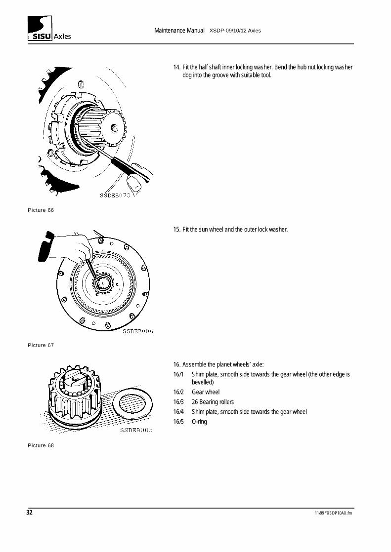
14. Fit the half shaft inner locking washer. Bend the hub nut locking washer dog into the groove with suitable tool.
Picture 66
15. Fit the sun wheel and the outer lock washer.
Picture 67
16. Assemble the planet wheels’ axle:
16/1 Shim plate, smooth side towards the gear wheel (the other edge is bevelled)
16/2 Gear wheel
16/3 26 Bearing rollers
16/4 Shim plate, smooth side towards the gear wheel
16/5 O-ring
Picture 68
32 11/99 * XSDP10AX.fm
Maintenance Manual XSDP-09/10/12 Axles
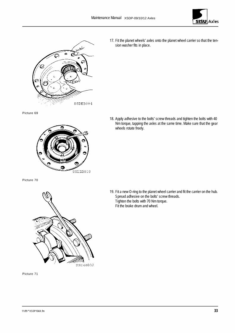
17. Fit the planet wheels’ axles onto the planet wheel carrier so that the ten-sion washer fits in place.
Picture 69
18. Apply adhesive to the bolts’ screw threads and tighten the bolts with 40 Nm torque, tapping the axles at the same time. Make sure that the gear wheels rotate freely.
Picture 70
19. Fit a new O-ring to the planet wheel carrier and fit the carrier on the hub. Spread adhesive on the bolts’ screw threads.Tighten the bolts with 70 Nm torque.Fit the brake drum and wheel.
Picture 71
11/99 * XSDP10AX.fm 33
Maintenance Manual XSDP-09/10/12 Axles
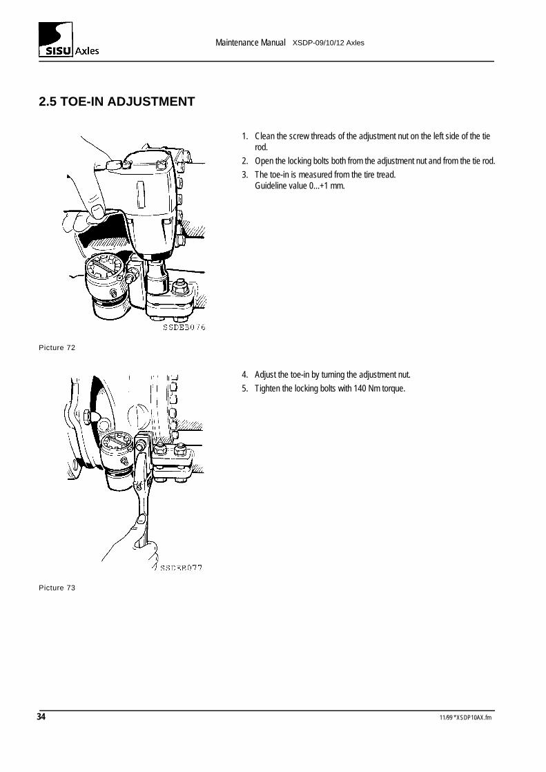
2.5 TOE-IN ADJUSTMENT
1. Clean the screw threads of the adjustment nut on the left side of the tie rod.
2. Open the locking bolts both from the adjustment nut and from the tie rod.
3. The toe-in is measured from the tire tread.Guideline value 0...+1 mm.
Picture 72
4. Adjust the toe-in by turning the adjustment nut.
5. Tighten the locking bolts with 140 Nm torque.
Picture 73
34 11/99 * XSDP10AX.fm
Maintenance Manual XSDP-09/10/12 Axles
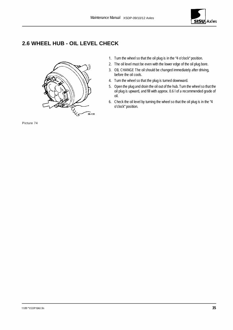
2.6 WHEEL HUB - OIL LEVEL CHECK
1. Turn the wheel so that the oil plug is in the “4 o’clock“ position.
2. The oil level must be even with the lower edge of the oil plug bore.
3. OIL CHANGE The oil should be changed immediately after driving, before the oil cools.
4. Turn the wheel so that the plug is turned downward.
5. Open the plug and drain the oil out of the hub. Turn the wheel so that the oil plug is upward, and fill with approx. 0.6 l of a recommended grade of oil.
6. Check the oil level by turning the wheel so that the oil plug is in the “4 o’clock“ position.
Picture 74
11/99 * XSDP10AX.fm 35
Maintenance Manual XSDP-09/10/12 Axles
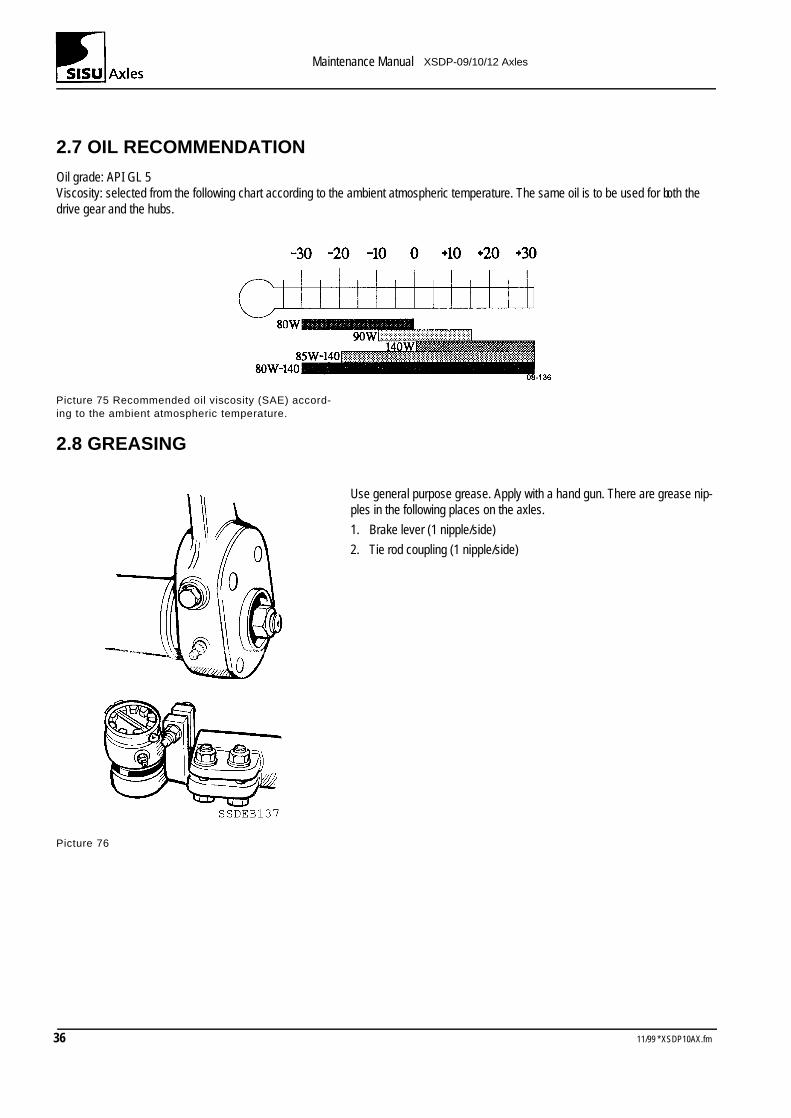
2.7 OIL RECOMMENDATION
Oil grade: API GL 5Viscosity: selected from the following chart according to the ambient atmospheric temperature. The same oil is to be used for both the drive gear and the hubs.
Picture 75 Recommended oil viscosity (SAE) accord-ing to the ambient atmospheric temperature.
2.8 GREASING
Use general purpose grease. Apply with a hand gun. There are grease nip-ples in the following places on the axles.
1. Brake lever (1 nipple/side)
2. Tie rod coupling (1 nipple/side)
Picture 76
36 11/99 * XSDP10AX.fm
Maintenance Manual XSDP-09/10/12 Axles
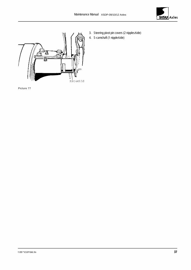
3. Steering pivot pin covers (2 nipples/side)
4. S-camshaft (1 nipple/side)
Picture 77
11/99 * XSDP10AX.fm 37

Maintenance Manual XSDP-09/10/12 Axles
38 11/99 * XSDP10AX.fm
Maintenance Manual XSDP-09/10/12 Axles
3 Brakes
3.1 SERVICING
3.1.1 Lubrication
To ensure long, trouble-free operation, it is essential to service the brakes carefully and at regular intervals. The service required is pre-sented below.Use a good grade of chassis grease. At each service, squeeze grease into the brake slack adjusters and S-camshaft bearings. Before greasing, clean the nipple heads carefully to prevent any dirt getting into the bearings.While greasing the S-camshaft bearings, it is advisable to depress and release the brake pedal so that the grease spreads more evenly on the bearing surfaces.Over-greasing must be avoided, as the excess grease may get into the brake drum.
3.1.2 Inspection
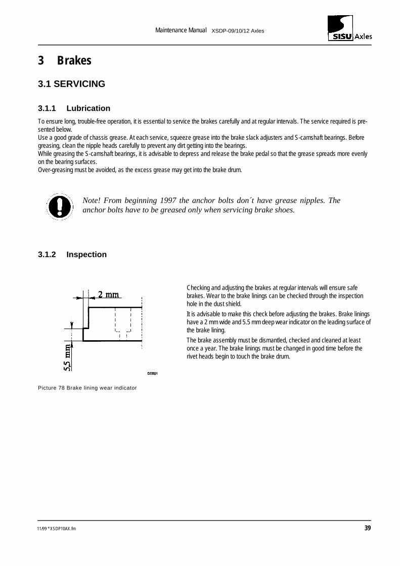
Checking and adjusting the brakes at regular intervals will ensure safe brakes. Wear to the brake linings can be checked through the inspection hole in the dust shield.
It is advisable to make this check before adjusting the brakes. Brake linings have a 2 mm wide and 5.5 mm deep wear indicator on the leading surface of the brake lining.
The brake assembly must be dismantled, checked and cleaned at least once a year. The brake linings must be changed in good time before the rivet heads begin to touch the brake drum.
Picture 78 Brake lining wear indicator
Note! From beginning 1997 the anchor bolts don´t have grease nipples. Theanchor bolts have to be greased only when servicing brake shoes.
11/99 * XSDP10AX.fm 39
Maintenance Manual XSDP-09/10/12 Axles
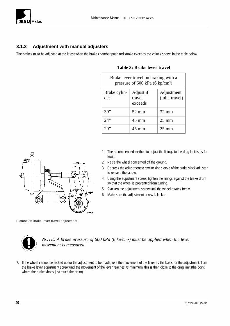
3.1.3 Adjustment with manual adjusters
The brakes must be adjusted at the latest when the brake chamber push rod stroke exceeds the values shown in the table below.
1. The recommended method to adjust the linings to the drag limit is as fol-lows:
2. Raise the wheel concerned off the ground.
3. Depress the adjustment screw locking sleeve of the brake slack adjuster to release the screw.
4. Using the adjustment screw, tighten the linings against the brake drum so that the wheel is prevented from turning.
5. Slacken the adjustment screw until the wheel rotates freely.
6. Make sure the adjustment screw is locked.
Picture 79 Brake lever travel adjustment
7. If the wheel cannot be jacked up for the adjustment to be made, use the movement of the lever as the basis for the adjustment. Turn the brake lever adjustment screw until the movement of the lever reaches its minimum; this is then close to the drag limit (the point where the brake shoes just touch the drum).
Table 3: Brake lever travel
Brake lever travel on braking with a pressure of 600 kPa (6 kp/cm²)
Brake cylin-der
Adjust if travel exceeds
Adjustment (min. travel)
30” 52 mm 32 mm
24” 45 mm 25 mm
20” 45 mm 25 mm
NOTE: A brake pressure of 600 kPa (6 kp/cm²) must be applied when the levermovement is measured.
40 11/99 * XSDP10AX.fm
Maintenance Manual XSDP-09/10/12 Axles
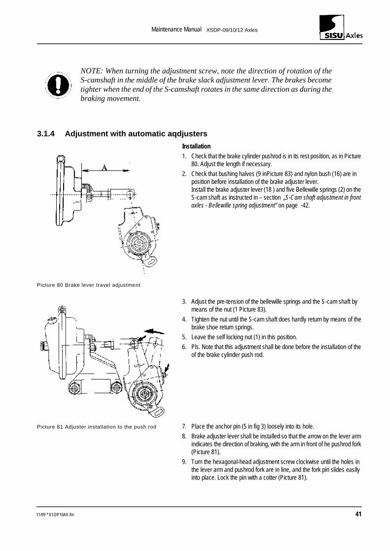
3.1.4 Adjustment with automatic aqdjusters
Installation
1. Check that the brake cylinder pushrod is in its rest position, as in Picture 80. Adjust the length if necessary.
2. Check that bushing halves (9 inPicture 83) and nylon bush (16) are in position before installation of the brake adjuster lever.Install the brake adjuster lever (18 ) and five Bellewille springs (2) on the S-cam shaft as instructed in – section „S-Cam shaft adjustment in front axles - Bellewille spring adjustment” on page -42.
Picture 80 Brake lever travel adjustment
3. Adjust the pre-tension of the bellewille springs and the S-cam shaft by means of the nut (1 Picture 83).
4. Tighten the nut until the S-cam shaft does hardly return by means of the brake shoe return springs.
5. Leave the self locking nut (1) in this position.
6. Pls. Note that this adjustment shall be done before the installation of the of the brake cylinder push rod.
Picture 81 Adjuster installation to the push rod 7. Place the anchor pin (5 in fig 3) loosely into its hole.
8. Brake adjuster lever shall be installed so that the arrow on the lever arm indicates the direction of braking, with the arm in front of he pushrod fork (Picture 81).
9. Turn the hexagonal-head adjustment screw clockwise until the holes in the lever arm and pushrod fork are in line, and the fork pin slides easily into place. Lock the pin with a cotter (Picture 81).
NOTE: When turning the adjustment screw, note the direction of rotation of theS-camshaft in the middle of the brake slack adjustment lever. The brakes becometighter when the end of the S-camshaft rotates in the same direction as during thebraking movement.
11/99 * XSDP10AX.fm 41
Maintenance Manual XSDP-09/10/12 Axles
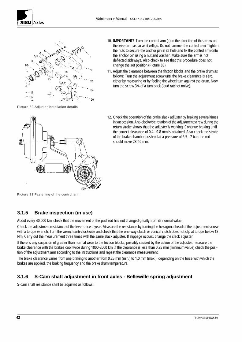
10. IMPORTANT! Turn the control arm (s) in the direction of the arrow on the lever arm as far as it will go. Do not hammer the control arm! Tighten the nuts to secure the anchor pin in its hole and fix the control arm onto the anchor pin using a nut and washer. Make sure the arm is not deflected sideways. Also check to see that this procedure does not change the set position (Picture 83).
11. Adjust the clearance between the friction blocks and the brake drum as follows: Turn the adjustment screw until the brake clearance is zero, either by measuring or by feeling the wheel turn against the drum. Now turn the screw 3/4 of a turn back (loud ratchet noise).
Picture 82 Adjuster installation details
12. Check the operation of the brake slack adjuster by braking several times in succession. Anti-clockwise rotation of the adjustment screw during the return stroke shows that the adjuster is working. Continue braking until the correct clearance of 0.4 - 0.8 mm is obtained. Also check the stroke of the brake chamber pushrod at a pressure of 6.5 - 7 bar: the rod should move 23-40 mm.
Picture 83 Fastening of the control arm
3.1.5 Brake inspection (in use)
About every 40,000 km, check that the movement of the pushrod has not changed greatly from its normal value.
Check the adjustment resistance of the lever once a year. Measure the resistance by turning the hexagonal head of the adjustment screw with a torque wrench. Turn the wrench anti-clockwise and check that the one-way clutch or conical clutch does not slip at torque below 18 Nm. Carry out the measurement three times with the same slack adjuster. If slippage occurs, change the slack adjuster.
If there is any suspicion of greater than normal wear to the friction blocks, possibly caused by the action of the adjuster, measure the brake clearance with the brakes cool twice during 1000-2000 km. If the clearance is less than 0.25 mm (minimum value) check the posi-tion of the adjustment arm according to the instructions and repeat the clearance measurement.
The brake clearance varies from one braking to another from 0.25 mm (min.) to 1.0 mm (max.), depending on the force with which the brakes are applied, the braking frequency and the brake drum temperature.
3.1.6 S-Cam shaft adjustment in front axles - Bellewille spring adjustment
S-cam shaft resistance shall be adjusted as follows:
42 11/99 * XSDP10AX.fm
Maintenance Manual XSDP-09/10/12 Axles
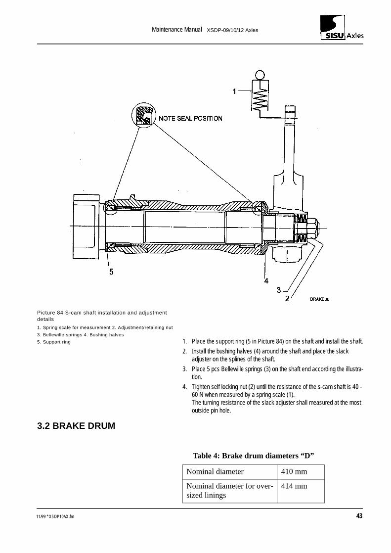
Picture 84 S-cam shaft installation and adjustment details
1. Spring scale for measurement 2. Adjustment/retaining nut
3. Bellewille springs 4. Bushing halves
5. Support ring 1. Place the support ring (5 in Picture 84) on the shaft and install the shaft.
2. Install the bushing halves (4) around the shaft and place the slack adjuster on the splines of the shaft.
3. Place 5 pcs Bellewille springs (3) on the shaft end according the illustra-tion.
4. Tighten self locking nut (2) until the resistance of the s-cam shaft is 40 - 60 N when measured by a spring scale (1).The turning resistance of the slack adjuster shall measured at the most outside pin hole.
3.2 BRAKE DRUM
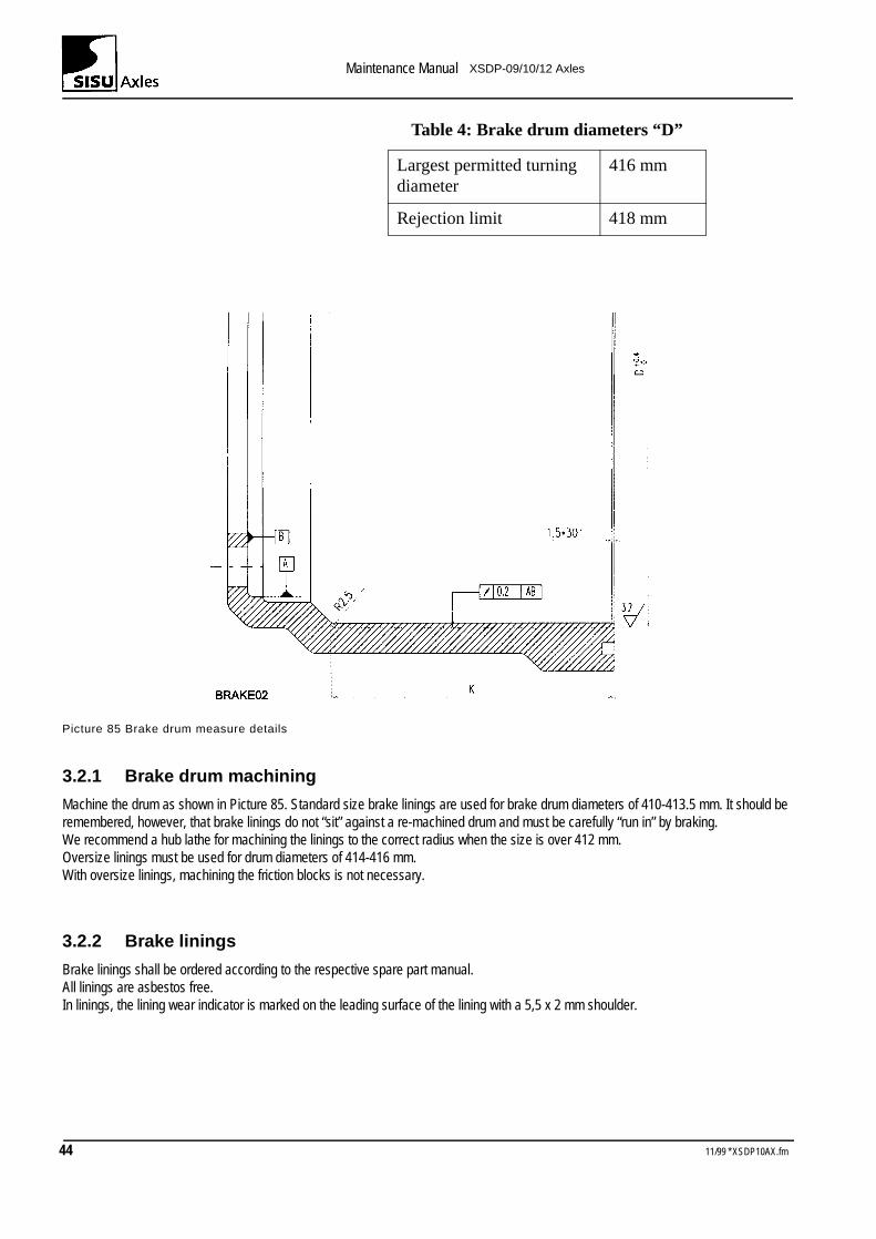
Table 4: Brake drum diameters “D”
Nominal diameter 410 mm
Nominal diameter for over-sized linings
414 mm
11/99 * XSDP10AX.fm 43
Maintenance Manual XSDP-09/10/12 Axles
Picture 85 Brake drum measure details
3.2.1 Brake drum machining
Machine the drum as shown in Picture 85. Standard size brake linings are used for brake drum diameters of 410-413.5 mm. It should be remembered, however, that brake linings do not “sit” against a re-machined drum and must be carefully “run in” by braking.We recommend a hub lathe for machining the linings to the correct radius when the size is over 412 mm.Oversize linings must be used for drum diameters of 414-416 mm.With oversize linings, machining the friction blocks is not necessary.
3.2.2 Brake linings
Brake linings shall be ordered according to the respective spare part manual.All linings are asbestos free.In linings, the lining wear indicator is marked on the leading surface of the lining with a 5,5 x 2 mm shoulder.
Largest permitted turning diameter
416 mm
Rejection limit 418 mm
Table 4: Brake drum diameters “D”
44 11/99 * XSDP10AX.fm
Maintenance Manual XSDP-09/10/12 Axles
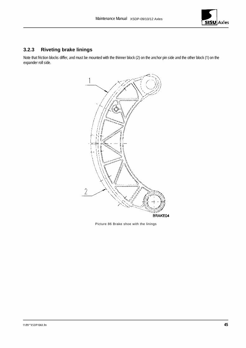
3.2.3 Riveting brake linings
Note that friction blocks differ, and must be mounted with the thinner block (2) on the anchor pin side and the other block (1) on the expander roll side.
Picture 86 Brake shoe with the linings
11/99 * XSDP10AX.fm 45
Maintenance Manual XSDP-09/10/12 Axles
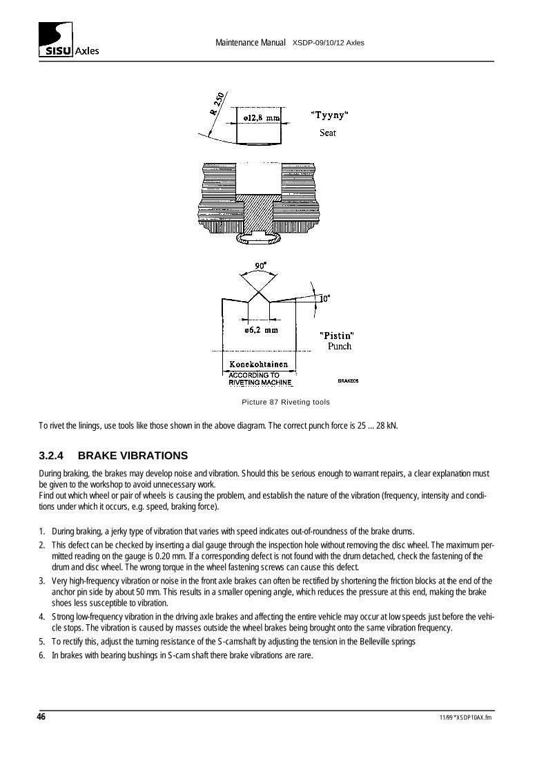
Picture 87 Riveting tools
To rivet the linings, use tools like those shown in the above diagram. The correct punch force is 25 ... 28 kN.
3.2.4 BRAKE VIBRATIONS
During braking, the brakes may develop noise and vibration. Should this be serious enough to warrant repairs, a clear explanation must be given to the workshop to avoid unnecessary work.Find out which wheel or pair of wheels is causing the problem, and establish the nature of the vibration (frequency, intensity and condi-tions under which it occurs, e.g. speed, braking force).
1. During braking, a jerky type of vibration that varies with speed indicates out-of-roundness of the brake drums.
2. This defect can be checked by inserting a dial gauge through the inspection hole without removing the disc wheel. The maximum per-mitted reading on the gauge is 0.20 mm. If a corresponding defect is not found with the drum detached, check the fastening of the drum and disc wheel. The wrong torque in the wheel fastening screws can cause this defect.
3. Very high-frequency vibration or noise in the front axle brakes can often be rectified by shortening the friction blocks at the end of the anchor pin side by about 50 mm. This results in a smaller opening angle, which reduces the pressure at this end, making the brake shoes less susceptible to vibration.
4. Strong low-frequency vibration in the driving axle brakes and affecting the entire vehicle may occur at low speeds just before the vehi-cle stops. The vibration is caused by masses outside the wheel brakes being brought onto the same vibration frequency.
5. To rectify this, adjust the turning resistance of the S-camshaft by adjusting the tension in the Belleville springs
6. In brakes with bearing bushings in S-cam shaft there brake vibrations are rare.
46 11/99 * XSDP10AX.fm
Maintenance Manual XSDP-09/10/12 Axles
.
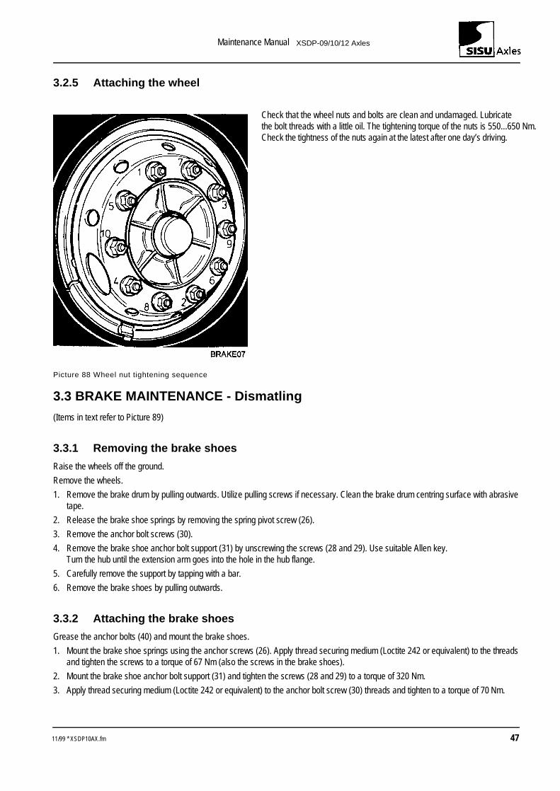
3.2.5 Attaching the wheel
Check that the wheel nuts and bolts are clean and undamaged. Lubricate the bolt threads with a little oil. The tightening torque of the nuts is 550...650 NmCheck the tightness of the nuts again at the latest after one day’s driving.
Picture 88 Wheel nut tightening sequence
3.3 BRAKE MAINTENANCE - Dismatling
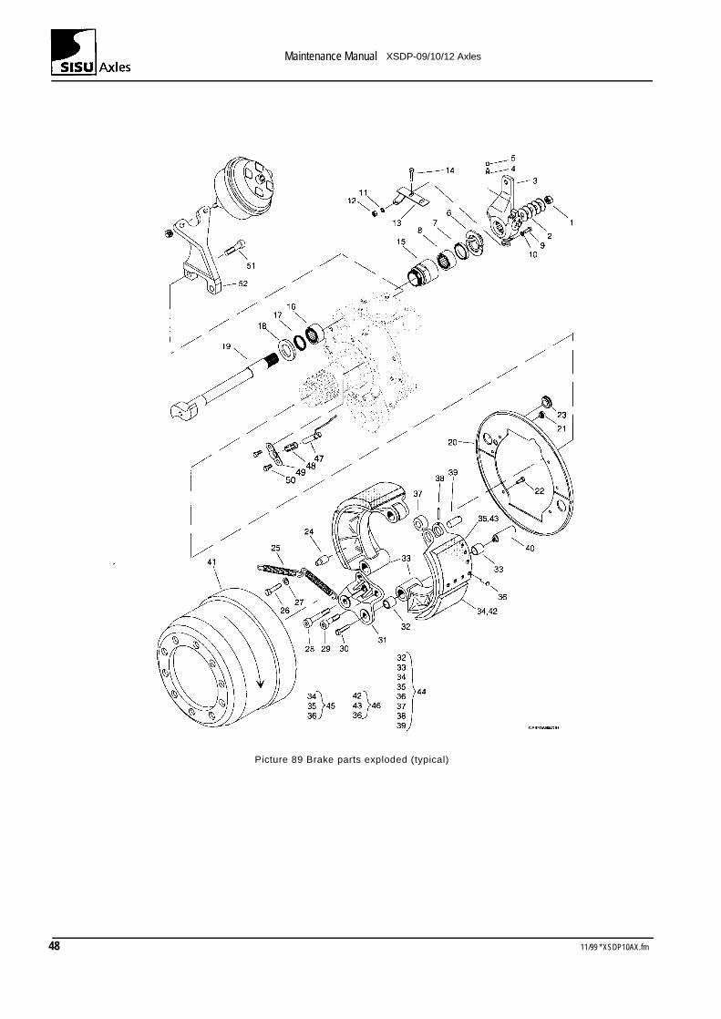
(Items in text refer to Picture 89)
3.3.1 Removing the brake shoes
Raise the wheels off the ground.
Remove the wheels.
1. Remove the brake drum by pulling outwards. Utilize pulling screws if necessary. Clean the brake drum centring surface with abrasive tape.
2. Release the brake shoe springs by removing the spring pivot screw (26).
3. Remove the anchor bolt screws (30).
4. Remove the brake shoe anchor bolt support (31) by unscrewing the screws (28 and 29). Use suitable Allen key.Turn the hub until the extension arm goes into the hole in the hub flange.
5. Carefully remove the support by tapping with a bar.
6. Remove the brake shoes by pulling outwards.
3.3.2 Attaching the brake shoes
Grease the anchor bolts (40) and mount the brake shoes.
1. Mount the brake shoe springs using the anchor screws (26). Apply thread securing medium (Loctite 242 or equivalent) to the threads and tighten the screws to a torque of 67 Nm (also the screws in the brake shoes).
2. Mount the brake shoe anchor bolt support (31) and tighten the screws (28 and 29) to a torque of 320 Nm.
3. Apply thread securing medium (Loctite 242 or equivalent) to the anchor bolt screw (30) threads and tighten to a torque of 70 Nm.
11/99 * XSDP10AX.fm 47
Maintenance Manual XSDP-09/10/12 Axles
Picture 89 Brake parts exploded (typical)
48 11/99 * XSDP10AX.fm
Maintenance Manual XSDP-09/10/12 Axles
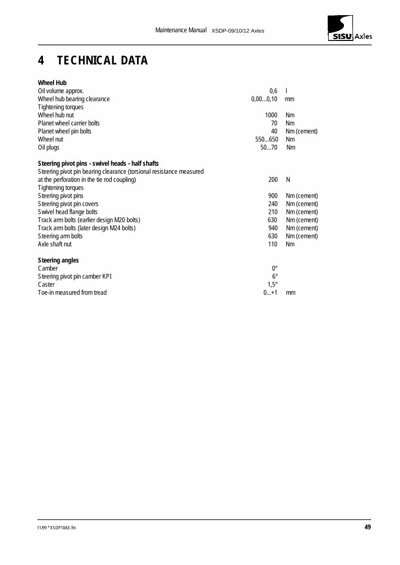
4 TECHNICAL DATA
Wheel HubOil volume approx. 0,6 lWheel hub bearing clearance 0,00...0,10 mmTightening torquesWheel hub nut 1000 NmPlanet wheel carrier bolts 70 NmPlanet wheel pin bolts 40 Nm (cement)Wheel nut 550...650 NmOil plugs 50...70 Nm
Steering pivot pins - swivel heads - half shaftsSteering pivot pin bearing clearance (torsional resistance measuredat the perforation in the tie rod coupling) 200 NTightening torquesSteering pivot pins 900 Nm (cement)Steering pivot pin covers 240 Nm (cement)Swivel head flange bolts 210 Nm (cement)Track arm bolts (earlier design M20 bolts) 630 Nm (cement)Track arm bolts (later design M24 bolts) 940 Nm (cement)Steering arm bolts 630 Nm (cement)Axle shaft nut 110 Nm
Steering anglesCamber 0°Steering pivot pin camber KPI 6°Caster 1,5°Toe-in measured from tread 0...+1 mm
11/99 * XSDP10AX.fm 49
Maintenance Manual XSDP-09/10/12 Axles
50 11/99 * XSDP10AX.fm
Maintenance Manual XSDP-09/10/12 Axles
5 SPECIAL TOOLS
Number: 7141 014 020
Name: Wheel hub wrench
11/99 * XSDP10AX.fm 51