Frost Formation Phenomenon in a Fin-and-Tube Heat Exchanger
8
Strojarstvo 50 (1) 15-22 (2008) K. LENIĆ et. al., Frost Formation Phenomenon in a Fin-and-Tube... 15 Frost Formation Phenomenon in a Fin-and-Tube... 15 15 CODEN STJSAO ISSN 0562-1887 ZX470/1328 UDK 536.2:621.565.93:621.565.3:519.63(043) Original scientific paper A transient two-dimensional mathematical model of frost formation on a fin-and-tube heat exchanger has been developed and numerically solved. The mathematical model and numerical procedure have been experimentally validated. The results have shown that frost layer formation significantly influences heat transfer between air and a refrigerant. Frost layer growth is faster with higher inlet air humidity. Using the developed mathematical model, the algorithm and the computer code, which have been experimentally validated, it is possible to predict frost layer growth on fin-and-tube heat exchangers under different operating conditions. Pojava stvaranja leda u lamelnom izmjenjivaču topline Izvornoznanstveni članak U radu je opisan nestacionarni dvodimenzijski matematički model nastanka ledenog sloja na lamelnom izmjenjivaču topline koji je riješen numeričkim putem. Matematički model i postupak numeričkog rješavanja provjereni su eksperimentalno. Rezultati su pokazali da stvaranje ledenog sloja značajno utječe na izmjenu topline između zraka i radne tvari u izmjenjivaču. Brzina rasta ledenog sloja veća je pri većim ulaznim vlažnostima zraka. Koristeći razvijeni matematički model, algoritam i eksperimentalno potvrđeni raču- nalni program moguće je predvidjeti smanjenje izmijenjenog toplinskog toka u izmjenjivaču topline pri različitim radnim uvjetima. kristian LENić and anica TrP Tehnički fakultet Sveučilišta u Rijeci (University of Rijeka Faculty of Engineering), Vukovarska 58, HR - 51000 Rijeka, Republic of Croatia Keywords Fin-and-tube heat exchanger Frost layer formation Numerical analysis Ključne riječi Lamelni izmjenjivač topline Nastanak ledenog sloja Numerička analiza Received (primljeno): 2007-04-25 Accepted (prihvaćeno): 2007-12-01 Frost Formation Phenomenon in a Fin-and-Tube Heat Exchanger [email protected] 1. Introduction Frost formation that occurs when moist air near cold surfaces has been cooled below freezing temperature of water is a very common phenomenon in refrigeration. The porous structure of frost layer consists of ice crystals and air gaps [1]. Whereas a frost layer contains air pores with low thermal conductivity, the whole frost layer represents significant thermal resistance. The thermal resistance of the frost layer and reduction of airflow due to an augmented pressure drop, causes a significant decrease of heat exchanger efficiency. This has an effect on space cooling quality and working behaviour of the whole device [2]. The principal aim of frost formation analysis is estimation of an exchanged heat flux under transient conditions of augmented thermal resistance. The frost formation process depends on water vapour transfer from an air stream into a frost layer, the diffusion rate of water vapour into the frost layer and thermal conduction inside the layer. One part of the water vapour flux, that transfers from the air stream, has been deposited on the frost surface and increases the frost thickness. The other part of the water vapour flux enters the frost layer and thus increases its density. The accuracy of determination of water mass flux that enters the frost layer has a crucial influence on the accuracy of determination of frost layer growth rate. Many authors divide the whole frost formation process into three different periods: crystal growth period, frost growth period and fully-developed frost formation period [3]. The majority of models developed so far can be classified into several groups. One is the group of models that predict variations of frost properties from the diffusion equation applied to the frost layer and then the amount of heat and mass transfer in the frost layer is calculated by using the correlations on the airside. This approach is used by K. S. Lee et al. [4], B. W. Jones et al. [5] and A. Z. Sahin [6]. The second group of modelling methods give some improvements: they analyze the air-flow with boundary layer equations and predict the frost properties by using the correlations. K. S. Lee et al. [7] developed a mathematical model without using the correlations for
Transcript of Frost Formation Phenomenon in a Fin-and-Tube Heat Exchanger

Strojarstvo 50 (1) 15-22 (2008) K. LENIĆ et. al., Frost Formation Phenomenon in a Fin-and-Tube... 15Frost Formation Phenomenon in a Fin-and-Tube... 15 15
CODEN STJSAO ISSN 0562-1887 ZX470/1328 UDK 536.2:621.565.93:621.565.3:519.63(043)
Original scientific paperA transient two-dimensional mathematical model of frost formation on a fin-and-tube heat exchanger has been developed and numerically solved. The mathematical model and numerical procedure have been experimentally validated. The results have shown that frost layer formation significantly influences heat transfer between air and a refrigerant. Frost layer growth is faster with higher inlet air humidity. Using the developed mathematical model, the algorithm and the computer code, which have been experimentally validated, it is possible to predict frost layer growth on fin-and-tube heat exchangers under different operating conditions.
Pojava stvaranja leda u lamelnom izmjenjivaču toplineIzvornoznanstveni članak
U radu je opisan nestacionarni dvodimenzijski matematički model nastanka ledenog sloja na lamelnom izmjenjivaču topline koji je riješen numeričkim putem. Matematički model i postupak numeričkog rješavanja provjereni su eksperimentalno. Rezultati su pokazali da stvaranje ledenog sloja značajno utječe na izmjenu topline između zraka i radne tvari u izmjenjivaču. Brzina rasta ledenog sloja veća je pri većim ulaznim vlažnostima zraka. Koristeći razvijeni matematički model, algoritam i eksperimentalno potvrđeni raču-nalni program moguće je predvidjeti smanjenje izmijenjenog toplinskog toka u izmjenjivaču topline pri različitim radnim uvjetima.
kristian LENić and anica TrP
Tehnički fakultet Sveučilišta u Rijeci (University of Rijeka Faculty of Engineering),Vukovarska 58,HR - 51000 Rijeka,Republic of Croatia
KeywordsFin-and-tube heat exchanger Frost layer formation Numerical analysis
Ključne riječiLamelni izmjenjivač topline Nastanak ledenog sloja Numerička analiza
Received (primljeno): 2007-04-25 Accepted (prihvaćeno): 2007-12-01
Frost Formation Phenomenon in a Fin-and-Tube Heat Exchanger
1. Introduction
Frost formation that occurs when moist air near cold surfaces has been cooled below freezing temperature of water is a very common phenomenon in refrigeration. The porous structure of frost layer consists of ice crystals and air gaps [1]. Whereas a frost layer contains air pores with low thermal conductivity, the whole frost layer represents significant thermal resistance. The thermal resistance of the frost layer and reduction of airflow due to an augmented pressure drop, causes a significant decrease of heat exchanger efficiency. This has an effect on space cooling quality and working behaviour of the whole device [2]. The principal aim of frost formation analysis is estimation of an exchanged heat flux under transient conditions of augmented thermal resistance.
The frost formation process depends on water vapour transfer from an air stream into a frost layer, the diffusion rate of water vapour into the frost layer and thermal conduction inside the layer. One part of the water vapour flux, that transfers from the air stream, has been deposited
on the frost surface and increases the frost thickness. The other part of the water vapour flux enters the frost layer and thus increases its density. The accuracy of determination of water mass flux that enters the frost layer has a crucial influence on the accuracy of determination of frost layer growth rate. Many authors divide the whole frost formation process into three different periods: crystal growth period, frost growth period and fully-developed frost formation period [3].
The majority of models developed so far can be classified into several groups. One is the group of models that predict variations of frost properties from the diffusion equation applied to the frost layer and then the amount of heat and mass transfer in the frost layer is calculated by using the correlations on the airside. This approach is used by K. S. Lee et al. [4], B. W. Jones et al. [5] and A. Z. Sahin [6]. The second group of modelling methods give some improvements: they analyze the air-flow with boundary layer equations and predict the frost properties by using the correlations. K. S. Lee et al. [7] developed a mathematical model without using the correlations for

16 K. LENIĆ et. al., Frost Formation Phenomenon in a Fin-and-Tube... Strojarstvo 50 (1) 15-22 (2008)
Symbols/Oznake
c – specific heat, J·kg-1·K-1 – specifična toplinaD – diffusivity, m2·s-1 – difuzivnostl – domain length, m – duljina domenemz – water vapour mass flux, kg·m-2·s-1
– maseni tok vodene parep – pressure, Pa – tlakS – supersaturation degree – razmak među lamelamat – time, s – vrijemeux – x-velocity component, m·s-1 – komponenta brzine u smjeru x-koordinatne oseuy – y-velocity component, m·s-1 – komponenta brzine u smjeru y-koordinatne osew – mass fraction of water vapour in air, kg·kg-1 – maseni udio vodene pare u zrakux – coordinate, m – koordinatey – coordinate, m – koordinateε – porosity – porozivnostη – dynamic viscosity, kg·s-1·m-1 – dinamički viskozitetϑ – temperature, ºC – temperatura
λ – thermal conductivity, W·m-1·K-1 – koeficijent toplinske vodljivostiρ – density, kg·m-3 – gustoćaτ – tortuosity factor – stupanj krivudavosti
Subscripts/indeksia – air – zrakdiff – related to diffusion in to frost layer – koji se širi difuzijom
eff – effective – efektivnofl – frost layer – ledeni slojfs – frost surface – površina ledenog slojas – fin surface – površina lamelein – inlet – ulazsat – saturated – zasićenov – water vapour – vodena paraΔy – related to layer thickness increase – koji povećava debljinu ledenog sloja0 – initial value – početna vrijednost
the air boundary layer zone and frost layer zone. Le Gall et al. [8] developed a transient one-dimensional model for frost growth and frost density change formed on cooled surfaces in the humid air stream. Lüer and Beer [9] theoretically and experimentally investigated the frost formation process on parallel plates in a humid air stream in laminar flow. Na and Webb [10,11] investigated basic phenomena related to frost layer formation and growth. They experimentally measured water vapour mass flux from an air stream to the frost layer. Through analysis of measured data, they stated that the partial pressure of water vapour on the frost layer surface is greater than the partial pressure of water vapour for the temperature of the frost layer surface, i.e. that air near the surface of the frost layer is supersaturated. Considerable work has been
done in the field of wavy fin-and-tube heat exchanger analyses, but only on the aspect of heat transfer, whilst mass transfer has not been taken into account [12].
A number of assumptions have been used in all of the abovementioned models, causing some divergence regarding the real physical process. This indicates the necessity for further investigations in that field.
As a first improvement, a calculation of air velocity, temperature and humidity fields has been performed allowing for a more exact description of heat and mass transfer. Furthermore, the problem has been solved as transient and two-dimensional. In the presented mathematical model, some of the latest results from previous models have been introduced including determination of air state at air-frost interface [13].
Strojarstvo 50 (1) 15-22 (2008) K. LENIĆ et. al., Frost Formation Phenomenon in a Fin-and-Tube... 17Frost Formation Phenomenon in a Fin-and-Tube... 17 17
2. Mathematical model
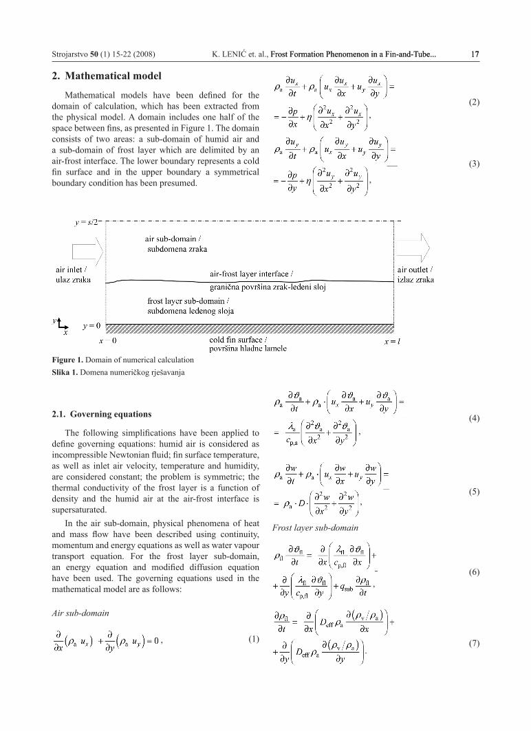
Mathematical models have been defined for the domain of calculation, which has been extracted from the physical model. A domain includes one half of the space between fins, as presented in Figure 1. The domain consists of two areas: a sub-domain of humid air and a sub-domain of frost layer which are delimited by an air-frost interface. The lower boundary represents a cold fin surface and in the upper boundary a symmetrical boundary condition has been presumed.
Figure 1. Domain of numerical calculationSlika 1. Domena numeričkog rješavanja
2.1. Governing equations
The following simplifications have been applied to define governing equations: humid air is considered as incompressible Newtonian fluid; fin surface temperature, as well as inlet air velocity, temperature and humidity, are considered constant; the problem is symmetric; the thermal conductivity of the frost layer is a function of density and the humid air at the air-frost interface is supersaturated.
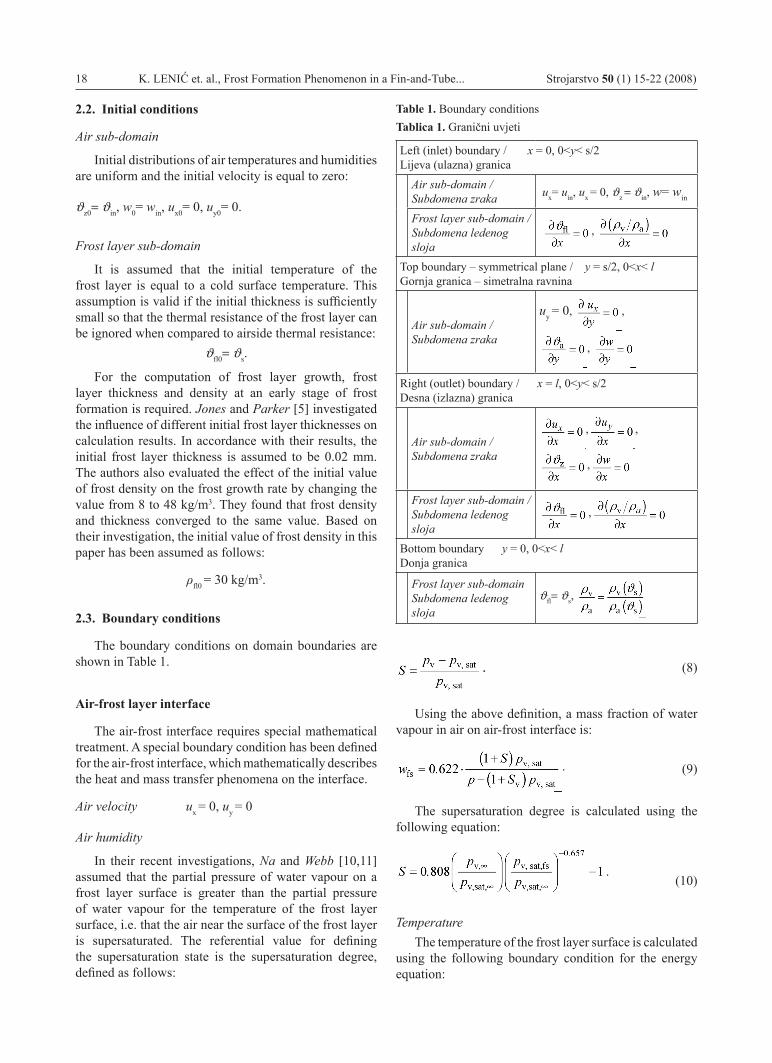
In the air sub-domain, physical phenomena of heat and mass flow have been described using continuity, momentum and energy equations as well as water vapour transport equation. For the frost layer sub-domain, an energy equation and modified diffusion equation have been used. The governing equations used in the mathematical model are as follows:
Air sub-domain
,
(1)
(2)
(3)
(4)
(5)
Frost layer sub-domain
(6)
(7)
,
,
,
,
,
.
18 K. LENIĆ et. al., Frost Formation Phenomenon in a Fin-and-Tube... Strojarstvo 50 (1) 15-22 (2008)
2.2. Initial conditions
Air sub-domain
Initial distributions of air temperatures and humidities are uniform and the initial velocity is equal to zero:
ϑz0= ϑin, w0= win, ux0= 0, uy0= 0.
Frost layer sub-domain
It is assumed that the initial temperature of the frost layer is equal to a cold surface temperature. This assumption is valid if the initial thickness is sufficiently small so that the thermal resistance of the frost layer can be ignored when compared to airside thermal resistance:
ϑfl0= ϑs.
For the computation of frost layer growth, frost layer thickness and density at an early stage of frost formation is required. Jones and parker [5] investigated the influence of different initial frost layer thicknesses on calculation results. In accordance with their results, the initial frost layer thickness is assumed to be 0.02 mm. The authors also evaluated the effect of the initial value of frost density on the frost growth rate by changing the value from 8 to 48 kg/m3. They found that frost density and thickness converged to the same value. Based on their investigation, the initial value of frost density in this paper has been assumed as follows:
ρfl0 = 30 kg/m3.
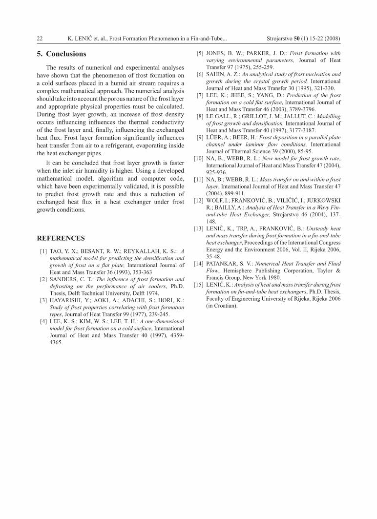
2.3. Boundary conditions
The boundary conditions on domain boundaries are shown in Table 1.
Air-frost layer interface
The air-frost interface requires special mathematical treatment. A special boundary condition has been defined for the air-frost interface, which mathematically describes the heat and mass transfer phenomena on the interface.
Air velocity ux = 0, uy = 0
Air humidity
In their recent investigations, Na and Webb [10,11] assumed that the partial pressure of water vapour on a frost layer surface is greater than the partial pressure of water vapour for the temperature of the frost layer surface, i.e. that the air near the surface of the frost layer is supersaturated. The referential value for defining the supersaturation state is the supersaturation degree, defined as follows:
Table 1. Boundary conditionsTablica 1. Granični uvjeti
Left (inlet) boundary / x = 0, 0<y< s/2 Lijeva (ulazna) granica
Air sub-domain /Subdomena zraka ux= uin, ux = 0, ϑz = ϑin, w= win
Frost layer sub-domain /Subdomena ledenog sloja
,
Top boundary – symmetrical plane / y = s/2, 0<x< l Gornja granica – simetralna ravnina
Air sub-domain /Subdomena zraka
uy = 0,
,
,
Right (outlet) boundary / x = l, 0<y< s/2 Desna (izlazna) granica
Air sub-domain /Subdomena zraka
, ,
,
Frost layer sub-domain /Subdomena ledenog sloja
,
Bottom boundary y = 0, 0<x< lDonja granica
Frost layer sub-domainSubdomena ledenog sloja
ϑfl= ϑs,
. (8)
Using the above definition, a mass fraction of water vapour in air on air-frost interface is:
.
(9)
The supersaturation degree is calculated using the following equation:
.
(10)
TemperatureThe temperature of the frost layer surface is calculated
using the following boundary condition for the energy equation:

Strojarstvo 50 (1) 15-22 (2008) K. LENIĆ et. al., Frost Formation Phenomenon in a Fin-and-Tube... 19Frost Formation Phenomenon in a Fin-and-Tube... 19 19
.
(11)
Density of new frost created at the frost surfaceIt is assumed that the density of new frost is equal to
the frost density at the surface:
.
Velocity of frost surface movingOne part of the water vapour mass flux which
transfers from the air stream, has been deposited on the frost surface and increases the frost thickness. The other part of the water vapour flux enters the frost layer and increases its density, Figure 2:
m m mya diff= +∆ . (12)
Figure 2. Water vapour mass fluxes on frost layer surfaceSlika 2. Maseni tokovi vodene pare na površini ledenog sloja
Frost layer growth rate has been calculated using total water vapour mass flux and diffusive mass flux on a frost layer surface. The mass flux density of water vapour transferring from air to a frost layer surface is proportional to the gradient of air humidity:
.
(13)
The mass flux density, which increases the frost layer, density absorbed by the frost layer is given by:
.
(14)
The mass flux density responsible for layer thickness growth is:
.
(15)
The frost layer growth rate is thus:
. (16)
Physical properties of the frost layer
The effective thermal conductivity of the frost layer is related to frost density. In this study, the following correlation proposed by Lee et al. [7] is used:
. (17)
The specific heat of the frost layer is obtained from the densities and specific heats of ice and humid air as well as density and porosity of the frost layer using:
.
(18)
The effective diffusion coefficient, as proposed by Na and Webb [10,11], has been calculated using:
,
(19)
where tortuosity factor is defined as follows:
.
(20)
3. Numerical solution and experimental validation
The control volume method has been used for the discretisation of the governing equations. Staggered grids for velocity components have been used to avoid physically unrealistic pressure field in the air sub-domain. The convection-diffusion terms have been discretised using a power-law scheme and the resulting set of linearised discretisation equations have been solved using an iterative procedure. A fully implicit method has been used for time-stepping treatment. For the velocity-pressure coupling, the SIMPLER algorithm has been applied [14]. Physical property data have been stored in separate input files. The algorithm has been implemented in an originally written FORTRAN code and solved on a personal computer (2,6 GHz). A detailed description of the numerical approach has been given in [15].

20 K. LENIĆ et. al., Frost Formation Phenomenon in a Fin-and-Tube... Strojarstvo 50 (1) 15-22 (2008)
The validation of the numerical model and developed computer code has been analysed by comparison between numerical and experimental data. Inlet conditions during the experimental investigation have been used as input data in numerical simulations. An experimental line consisted of a cooled aluminium plate placed in a humid air stream with controlled inlet conditions. A detailed description of the experimental setup and procedure has been given in [15]. Time-wise, frost layer thickness variations with comparison of numerical and experimental data are shown in Figure 3.
Figure 3. Time-wise frost layer thickness variations – comparison of experimental and numerical values (ϑa,in = 21.4 °C, win = 0.0062 kg/kg, ux,in= 0.6 m/s, ϑfs = -19.5 °C) Slika 3. Vremenske promjene debljine ledenog sloja – –usporedba eksperimentalnih podataka i podataka dobivenih numeričkim rješavanjem
The comparison between numerical results and experimental data for frost layer growth in a humid air stream shows compatibility regarding trends of analysed variables. The obtained results indicate that a developed numerical procedure could be efficiently used to simulate the physical process of frost layer formation.
4. Calculation results and discussion
A numerical analysis was performed for a fin-and-tube heat exchanger with the following geometrical characteristics: fin thickness 0.001 m, space between fins 0.006 m, fin width 0.048 m, total number of pipes 189, total number of fins 210, heat exchanger surface 18 m2, longitudinal pipe distance 0.016 m, transversal pipe distance 0.014 m, outer pipe diameter 0.01 m and inside pipe diameter 0.008 m.
A set of numerical calculations has been performed in order to evaluate the influence of inlet air velocity, temperature and humidity on the frost growth rate. A numerical analysis has been carried out for different inlet air velocities, temperatures and humidities. Longitudinal distributions of frost layer thickness for different periods
of frost formation and different inlet humidities are shown in Figures 4 and 5. Velocity vector fields for different periods of frost formation and different inlet humidities are shown in Figures 6 and 7.
Figure 5. Longitudinal distributions of frost layer thickness for different periods of frost formation (ϑa,in = 12 °C, win = =0.006 kg/kg, ux,in= 1 m/s, ϑfs = -12 °C)Slika 5. Uzdužna raspodjela debljina ledenog sloja u različitim trenutcima nastanka sloja
Figure 6. Velocity vectors for different periods of frost formation (ϑa,in = 12 °C, win = 0.002 kg/kg, ux,in= 1 m/s, ϑfs = =-12 °C)Slika 6. Vektori brzina u različitim trenutcima nastanka ledenog sloja
Figure 4. Longitudinal distributions of frost layer thickness for different periods of frost formation (ϑa,in = 12 °C, win = =0.002 kg/kg, ux,in= 1 m/s, ϑfs = -12 °C)Slika 4. Uzdužna raspodjela debljina ledenog sloja u različitim trenutcima nastanka sloja

Strojarstvo 50 (1) 15-22 (2008) K. LENIĆ et. al., Frost Formation Phenomenon in a Fin-and-Tube... 21Frost Formation Phenomenon in a Fin-and-Tube... 21 21
Figure 7. Velocity vectors for different periods of frost formation (ϑa,in = 12 °C, win = 0.006 kg/kg, ux,in= 1 m/s, ϑfs = =-12 °C)Slika 7. Vektori brzina u različitim trenutcima nastanka ledenog sloja
Figure 8. Transversal distributions of temperatures for different periods of frost formation x = 15 mm (ϑa,in = 12 °C, win = 0.002 kg/kg, ux,in= 1 m/s, ϑfs = -12 °C)Slika 8. Poprečne raspodjele temepratura u različitim trenutcima nastanka ledenog sloja
Figure 9. Transversal distributions of temperatures for different periods of frost formation x = 15 mm (ϑa,in = 12 °C, win = 0.006 kg/kg, ux,in= 1 m/s, ϑfs = -12 °C)Slika 9. Poprečne raspodjele temepratura u različitim trenutcima nastanka ledenog sloja
Due to heat transfer from air to the frost layer, a cooling of air stream occurs near the frost surface. Distribution of the temperature field is stratified because the laminar flow has been assumed. The average temperature at the transversal cross-section becomes lower from inlet to outlet. During regular operation, the frost layer becomes thicker and frost surface temperature becomes higher due to increased thermal resistance.
In the case of higher inlet air humidity (win = 0.006 kg/kg) frost growth is more intensive compared to the case with lower inlet air humidity (win = 0.002 kg/kg). In the beginning, frost growth is more intensive at the inlet part of the heat exchanger when higher air humidity has been applied (win = 0.006 kg/kg). After 1.5 hours of operation, along the whole domain, the first and second phases of frost formation occur i.e. crystal growth phase and frost growth phase. The frost layer surface becomes rough, which can be attributed to the second phase of the frost formation process. At the inlet part (left side of the calculation domain), the frost layer is slightly thicker. As the frost layer grows, because of increased thermal resistance, the temperature of the frost layer surface becomes higher. When the frost surface temperature reaches 0 °C, the third phase of frost growth formation takes place. This initially occurs at the inlet boundary zone after 2 hours of operation. Then “the third phase zone” spreads towards the outlet boundary. At this moment, both the second and the third phase of frost formation are present.
Frost layer growth is more intensive under higher air humidity because of the higher gradient of air humidity near the frost surface in the boundary layer. This influence of air humidity on frost layer growth rate is significant.
Transversal distributions of temperatures at position x = 15 mm at 0.5 hour time intervals during frost formation are shown in Figures 8 and 9. It can be seen that temperature distributions inside the frost layer are linear. From the other side, in the air boundary layer the temperature distributions are non-linear. The point, at which the curve of temperature distribution changes its flow, represents the temperature of the frost layer surface. It can be noticed that under test conditions with high air humidity (win = 0.006 kg/kg) shown in Figure 9, the temperatures of the frost layer surface increase during the second phase of the frost layer formation process. After reaching the third phase of the frost formation process, a thermal equilibrium has been reached and temperatures do not change significantly (after 2.5 hours of operation). Under operating conditions with lower humidity (win = = 0.002 kg/kg), the third phase of frost formation is not reached during the first 3 hours, thus the temperature of frost surfaces is rising continuously, as shown in Figure 8.
22 K. LENIĆ et. al., Frost Formation Phenomenon in a Fin-and-Tube... Strojarstvo 50 (1) 15-22 (2008)
5. Conclusions
The results of numerical and experimental analyses have shown that the phenomenon of frost formation on a cold surfaces placed in a humid air stream requires a complex mathematical approach. The numerical analysis should take into account the porous nature of the frost layer and appropriate physical properties must be calculated. During frost layer growth, an increase of frost density occurs influencing influences the thermal conductivity of the frost layer and, finally, influencing the exchanged heat flux. Frost layer formation significantly influences heat transfer from air to a refrigerant, evaporating inside the heat exchanger pipes.
It can be concluded that frost layer growth is faster when the inlet air humidity is higher. Using a developed mathematical model, algorithm and computer code, which have been experimentally validated, it is possible to predict frost growth rate and thus a reduction of exchanged heat flux in a heat exchanger under frost growth conditions.
REFERENCES
[1] TAO, Y. X.; BESANT, R. W.; REYKALLAH, K. S.: A mathematical model for predicting the densification and growth of frost on a flat plate, International Journal of Heat and Mass Transfer 36 (1993), 353-363
[2] SANDERS, C. T.: The influence of frost formation and defrosting on the performance of air coolers, Ph.D. Thesis, Delft Technical University, Delft 1974.
[3] HAYARISHI, Y.; AOKI, A.; ADACHI, S.; HORI, K.: Study of frost properties correlating with frost formation types, Journal of Heat Transfer 99 (1977), 239-245.
[4] LEE, K. S.; KIM, W. S.; LEE, T. H.: A one-dimensional model for frost formation on a cold surface, International Journal of Heat and Mass Transfer 40 (1997), 4359-4365.
[5] JONES, B. W.; PARKER, J. D.: Frost formation with varying environmental parameters, Journal of Heat Transfer 97 (1975), 255-259.
[6] SAHIN, A. Z.: An analytical study of frost nucleation and growth during the crystal growth period, International Journal of Heat and Mass Transfer 30 (1995), 321-330.
[7] LEE, K.; JHEE, S.; YANG, D.: Prediction of the frost formation on a cold flat surface, International Journal of Heat and Mass Transfer 46 (2003), 3789-3796.
[8] LE GALL, R.; GRILLOT, J. M.; JALLUT, C.: Modelling of frost growth and densification, International Journal of Heat and Mass Transfer 40 (1997), 3177-3187.
[9] LÜER, A.; BEER, H.: Frost deposition in a parallel plate channel under laminar flow conditions, International Journal of Thermal Science 39 (2000), 85-95.
[10] NA, B.; WEBB, R. L.: New model for frost growth rate, International Journal of Heat and Mass Transfer 47 (2004), 925-936.
[11] NA, B.; WEBB, R. L.: Mass transfer on and within a frost layer, International Journal of Heat and Mass Transfer 47 (2004), 899-911.
[12] WOLF, I.; FRANKOVIĆ, B.; VILIČIĆ, I.; JURKOWSKI R.; BAILLY, A.: Analysis of Heat Transfer in a Wavy Fin-and-tube Heat Exchanger, Strojarstvo 46 (2004), 137-148.
[13] LENIĆ, K., TRP, A., FRANKOVIĆ, B.: Unsteady heat and mass transfer during frost formation in a fin-and-tube heat exchanger, Proceedings of the International Congress Energy and the Environment 2006, Vol. II, Rijeka 2006, 35-48.
[14] PATANKAR, S. V.: Numerical Heat Transfer and Fluid Flow, Hemisphere Publishing Corporation, Taylor & Francis Group, New York 1980.
[15] LENIĆ, K.: Analysis of heat and mass transfer during frost formation on fin-and-tube heat exchangers, Ph.D. Thesis, Faculty of Engineering University of Rijeka, Rijeka 2006 (in Croatian).