TECHNICAL INFORMATION HCC 2 · The heat exchanger is placed with upright standing lamella, which...
24
HOME VENTILATION UNIT FOR SUSPENDED CEILING TECHNICAL INFORMATION HCC 2
Transcript of TECHNICAL INFORMATION HCC 2 · The heat exchanger is placed with upright standing lamella, which...
H O M E V E N T I L AT I O N U N I T F O R S U S P E N D E D C E I L I N G
TECHNICAL INFORMATIONH CC 2


HCC 2 Home ventilation
GENERAL DESCRIPTION 4
CONTROL 11
TECHNICAL DATA 12
ACCESSORIES 17
1
2
3
4
With reservation for changes and misprints. August 2019.

- 4 -
1GENERAL DESCRIPTION
The HCC 2 home ventilation unit is primarily designed for new constructions or
retrofitting into multiple apartment buildings. The outer dimensions and design allow
easy installation into a suspended ceiling or onto a wall, hidden inside a closet.
The unit is supplied as a basic unit, with the option of fitting a wide range of
accessories into the unit, thus extending the comfort and reducing the energy
consumption.
The home ventilation unit is equipped with a highly efficient plastic counter-flow heat
exchanger, which is optimised to a high efficiency level. This, combined with a low
headroom, results in a very slim ventilation unit, easily hidden in a suspended ceiling,
together with the duct system.
Key Features
▶ High efficiency heat recovery – up to 94%
▶ EC fan motors with low energy consumption (SFP data)
▶ Only 300 mm installation headroom height is required.
▶ Time controlled ventilation level, based on 11 different built in pre-programmed
week programs. This reduces power consumption in periods with low ventilation
demands.
▶ Summer cooling mode, in which the supply fan is stopped, and any open window
will supply colder outside air, decreasing the room temperature. Summer cooling
mode requires a wired control HCP 10 (accessory).
▶ Fireplace mode, creating a momentary inside overpressure, to enhance chimney
functionality.
▶ Easy-to-install and commissioning solution with built in air measure ports, for easy
balancing with the PC Tool.
▶ Electronically left / right fan direction switching, allowing same unit type to adapt
any physical installation requirements, regardless of ceiling and wall selection.
▶ Demand controlled ventilation (accessory)
▶ Highly customisable unit, by adding a high variety of internal as well as external
accessories. See more details in the chapter “Accessories”.
▶ TCP ModBus connection, for inter-operation with Building Management System
GENERAL DESCRIPTION

GENERAL DESCRIPTION1
- 5 -
HCC 2 enclosureThe unit enclosure is designed to fit low headroom suspended ceilings, and yet still
with easy service access. The outer surface is 0.8 mm Aluzink powder coated sheet,
painted white in RAL 9010, with two external lids covering the two filter slots.
All inside air paths and insulation, is made of EPS (Polystyrene). This has a high
insulation level, and good air tightness. This insulation thickness permits location of the
units in spaces with temperatures down to +12°C .
Installation parts The enclosed mounting bracket is designed to conduct a safe installation process, and
is suitable for both wall and ceiling installation.
The mounting bracket will:
▶ Tilt the unit slightly towards the drainage spigot, ensuring correct drainage of any
condensed water inside the unit when used for ceiling installation.
▶ Offer a easy wall installation process
Mirroring all duct connectionsThe air flow direction can be electronically swapped, providing ability to route the
connected ducts, either to the right or to the left. This means that the supply air duct
connections can be either to the right or to the left hand side of the unit. (Supply air
and extract air duct connections always towards the inside of the house and outside
air and exhaust air ducts always towards the outside of the house).
All electrical cables can be connected from either the left or the right hand side,
regardless of fan direction.
FunctionThe unit ventilates residential homes by extracting the inside humid air, and
replacing it with fresh outside air, which has been heated with the heat energy of the
extracted air. This reduces energy consumption.
The air volume can be controlled by:
▶ Selecting a fixed fan speed between 0-4.
▶ Demand mode: By fitting the HCC 2 unit with optional VOC or RH sensors
(accessory) the fan speed is automatically adjusted to the actual demand,
determined by the quality and the relative humidity of the extracted air.
▶ 11 different week programs, where the fan speed will increase or decrease
according to an hourly time schedule.
When very humid inside air is extracted, the humidity will condensate inside the heat
exchanger, and be collected by the embedded drip tray. This water is drained from the
unit through the enclosed hose and then disposed of in the nearest drainage.
Universal mounting bracket
HCC 2 on wall
HCC 2 in suspended ceiling

- 6 -
1GENERAL DESCRIPTION
FiltersThe HCC 2 home ventilation unit uses 50 mm G4 compact filters as standard for both
supply air and extract air. This will cater for the majority of air cleaning needs. The
advantage of compact filters is that they have a considerably larger filter surface area
than fibrous filters and small bag-filters. The filter thus works for longer and under
normal conditions it will not need changing more often than once or twice a year.
If necessary, F7 filters (pollen filters) are available as accessories, which ensure that
allergens do not enter the home through the ventilation system.
FansThe HCC 2 home ventilation unit is equipped with the latest EC (Electromagnetic
Commutation) fan motor technology. I.e., use of modern motors and fan rotors offering
the very best in air technology and electrical efficiency. Thanks to the EC technology
the bearings are the only moving parts to produce resistance and therefore the lifetime
of these fans is approx. 10 years. The fans are connected to the controller of the fan unit
and powered by 230 V. Stepless fan speed controlled by a 0-10 volt signal.
RH% demand sensorThe residential ventilation units are fitted with a humidity sensor (RH%).
This sensor will continuously monitor the humidity of the extract air and adjust the
air flow level accordingly. This operation is named demand mode. If a wireless remote
control is connected, the level will be shown in the display using a 3 level icon.
Using demand mode will result in the correct level of ventilation at the lowest possible
electrical power consumption. If both VOC and RH% sensors are fitted, the ventilation
level is determined by the highest demand from just any one of the sensors.
G4 F7Filters
EC fan
RH% demand sensor

GENERAL DESCRIPTION1
- 7 -
Heat exchanger HCC 2 PLAHeat recovery takes place in a highly efficient counterflow heat exchanger made of
plastic material offering optimum efficiency with the lowest possible loss of pressure.
The heat exchanger is placed with upright standing lamella, which ensure correct self-
drainage by gravity, resulting in a very hygienic solution.
Frost protection of the heat exchanger:The intelligent control system of the HCC systems ensures that the heat exchanger
does not ice up in winter.
▶ Frost protection is activated if the exhaust air temperature (T4) is < +2°C, which
will usually occur when the outdoor air temperature (T1) falls below approx. –3°C.
▶ When the exhaust temperature (T4) falls to +2°C, the system reduces the volume
of supply air (T2) so that the final exhaust temperature (T4) is maintained at
minimum +2°C.
▶ If it is particularly cold, the supply air volume will be turned right down to 0 m3/h
for short intervals in order to keep the heat exchanger frost-free.
▶ If the outdoor air temperature (T1) falls below < -13°C for more than four minutes,
the system stops completely for 30 mins. in order to prevent icing up.
In areas where the outdoor temperatures often is lower than -6°C, we recommend to
mount pre-heating. In other areas, where the outdoor temperature may fall below -10
°C, preheating is a must for obtaining a balanced and reliable solution.
Heat exchanger HCC 2 (E1) HCC 2 E1 is fitted with an enthalpy exchanger that recovers both heat and humidity from
the extract air and transfers it to the fresh supply air. Transferring the humidity from the
extract air to the fresh supply air prevents a dry indoor climate during wintertime. In the
summer, when the relative humidity of the outdoor air is high, supply air will be dehumi-
dified when passing through the enthalpy exchanger. This makes the supply air feel com-
fortably cold. Because of their superb ability to recover both heat and humidity, enthalpy
exchangers are known to reduce heating costs substantially.
Mechanic bypass moduleThe HCC 2 home ventilation unit is fitted with an automatically controlled bypass
damper module that exploits the colder outdoor air to cool down the home, e.g.
after a hot summer’s day, when the outdoor night time temperature falls below the
temperature of the house. The bypass module leads all the hot exhaust air past the
heat exchanger in order to achieve the best possible cooling effect.
Mechanic bypass module
Enthalpy exchanger
Heat exchanger

- 8 -
1GENERAL DESCRIPTION
ControllerThe unit’s main controller measures and adjusts all parameters continuously in order to
maintain a correct ventilation level, with the lowest possible energy consumption. The
controller has a wide variety of connections, both for internal accessories as well as for
external.
The controller has a wide range of self-test and logging functions, enabling any
corrective maintenance specialist, to make quick and efficient corrections if needed.
As the HCC 2 home ventilation unit is designed for hidden installation, the basic unit
comes without built in control panel. Please see the chapter “Accessories” for more
details about the various control possibilities.
HCC external connections:The controller offers a wide range of connections, both for internal parts, as well as
external.
The following external connections are available:
▶ Antenna connection for communicating with the wireless remote control
(accessory)
▶ RJ 45 LAN connection, offering 2 way TCP ModBus data for integration with
building management system.
▶ RS-485 ModBus for HAC 2 accessory extension module and connection of wired
control H CP10
▶ 2 pcs. digital inputs, with several programmable options through PC Tool.
▶ Pre-heater output for connecting the Dantherm pre-heater (accessory)
Embedded controller
HCC unit External parts
Digital in
ModBus out for HAC only
Proprietary wireless remote
External pre-heater
Ethernet router with DHCP
HCC main controller
BMS systems (e.g. KNX)Fan 1 and Fan 2
Internal RH% sensor
USB service port
Bypass damper(accessory)
Internal VOC sensor
Overall system architecture schematics

GENERAL DESCRIPTION1
- 9 -
InstallationAfter installation of the unit, ducts and condensate hose, the unit needs to be
calibrated to the specific environment. Measurement of air volumes is done via built in
air pressure ports. The initial adjustments are performed through the Dantherm PC Tool
connected to the unit via a USB connection or by means of the wired control (HCP 10).
An air performance graph is adhered to the front cover, showing the pressure and air
volumes the installer must use to determine the correct fan speeds.
(Label example below.)
Safety operation – connection to a smoke or fire alarm systemIn order to protect the occupants from outside fire or smoke, it is possible to connect a
standard smoke/fire alarm system to the HCC 2 home ventilation unit. The smoke/fire
detection equipment can be connected to the accessory controller (HAC 2 accessory)
at the fire protection terminals. When activated the unit will give a fire alarm signal and
stop both fans to avoid more smoke/fire to enter from outside. Once the smoke/fire
danger is no longer present the unit must be restarted by power on/off again.
Alternatively, if the user is only interested in avoiding smoke from outside to enter
the home (during heating season when fireplaces are in use in the neighbourhood)
it is possible to use the digital input connection direct at the unit control to make the
unit stop when smoke is detected in the outdoor air intake. When using the digital
connection the unit will automatically restart when there is no longer smoke in the
outdoor air. Please note: Still, standard smoke detection equipment must be used for
the detection of smoke.
In case of higher risk of smoke/fire or higher safety requirements) it is also possible to
build duct dampers into the duct work and have the ventilation unit open/close these
whenever the unit is running/stopped. The damper motors (one for supply and one for
extract air) can be powered and controlled by the HAC 2 accessory controller.
MaintenanceIn general, the only regular maintenance required by the HCC home ventilation unit is
to check/change the air filters once or twice a year, when the alarm sounds from the
unit, or flashes on any connected controls.
Calibration
0
10
20
30
40
50
60
70
80
90
100
110
120
0 20 40 60 80 100 120 140 160 180 200
[Pa]
[m3/h]
- 10 -
1GENERAL DESCRIPTION
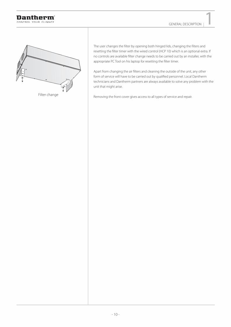
The user changes the filter by opening both hinged lids, changing the filters and
resetting the filter timer with the wired control (HCP 10) which is an optional extra. If
no controls are available filter change needs to be carried out by an installer, with the
appropriate PC Tool on his laptop for resetting the filter timer.
Apart from changing the air filters and cleaning the outside of the unit, any other
form of service will have to be carried out by qualified personnel. Local Dantherm
technicians and Dantherm partners are always available to solve any problem with the
unit that might arise.
Removing the front cover gives access to all types of service and repair.Filter change

CONTROL2
- 11 -
Control strategiesThe installation is secured against incorrect and uneconomical operation for long
periods of time. Several of the functions return to default after 4 hours as a means of
preventing excessive energy consumption, for instance if a unit is left running at
maximum fan speed or in manual bypass mode. If you switch off the installation, it will
automatically restart after 4 hours to ensure proper ventilation and to keep condensa-
tion from forming in the ducts and in the unit.
The unit is controlled at any time by the installer or by the user. By default the unit is
equipped with a USB connection, in order to let the installer do the initial calibration
and setup of the unit.
If the user needs interaction to the unit, at least one of the following accessories
needs to be purchased:
▶ Wired control (HCP 10)
▶ Wireless remote control (HRC 3)
▶ Dantherm PC Tool
Wired connection from MODBUS out, to a local building management system, can also
be used for two way communication.
During initial calibration, fan speed no. 3 is set on the control panel to the nominal air
volume that the house requires under normal usage.
The correlation between the four fan speeds on the control panel is as follows:
▶ Fan speed 0 = both fans stopped for 4 hours (4 hours timeout).
▶ Fan speed 1 = 30% lower than fan speed 2
▶ Fan speed 2 = 30% lower than fan speed 3
▶ Fan speed 3 = Nominal air change, set by installer during the initial calibration.
▶ Fan speed 4 = 30% higher than fan speed 3 (4 hours time out)
Filter controlThe filter pressure is expected to increase between filter change intervals. To compen-
sate for the reduced air volumes over time, the two fans run faster and faster until the
filter alarm is triggered and the filter timer has been reset.
CONTROL
- 12 -
3TECHNICAL DATA
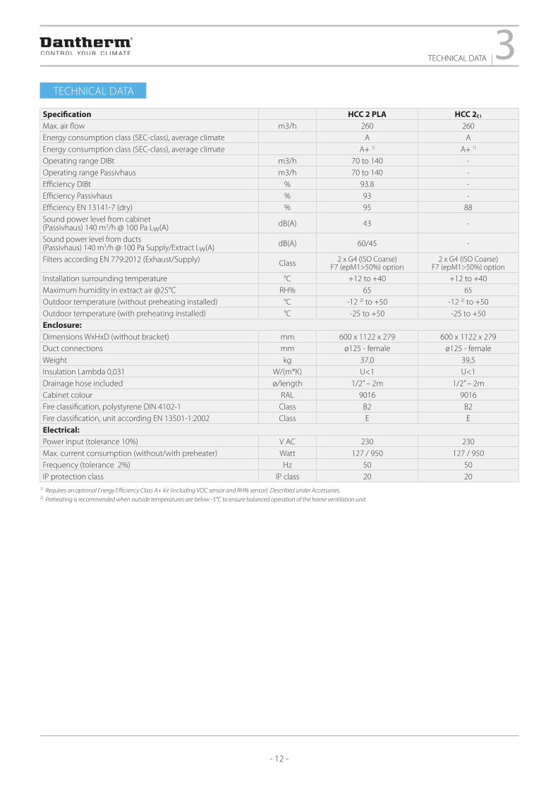
Specification HCC 2 PLA HCC 2E1
Max. air flow m3/h 260 260Energy consumption class (SEC-class), average climate A AEnergy consumption class (SEC-class), average climate A+ 1) A+ 1)
Operating range DIBt m3/h 70 to 140 -Operating range Passivhaus m3/h 70 to 140 -Efficiency DIBt % 93.8 -Efficiency Passivhaus % 93 -Efficiency EN 13141-7 (dry) % 95 88Sound power level from cabinet (Passivhaus) 140 m3/h @ 100 Pa Lw(A) dB(A) 43 -
Sound power level from ducts (Passivhaus) 140 m3/h @ 100 Pa Supply/Extract Lw(A) dB(A) 60/45 -
Filters according EN 779:2012 (Exhaust/Supply) Class 2 x G4 (ISO Coarse) F7 (epM1>50%) option
2 x G4 (ISO Coarse) F7 (epM1>50%) option
Installation surrounding temperature °C +12 to +40 +12 to +40Maximum humidity in extract air @25°C RH% 65 65
Outdoor temperature (without preheating installed) °C -12 2) to +50 -12 2) to +50Outdoor temperature (with preheating installed) °C -25 to +50 -25 to +50Enclosure:Dimensions WxHxD (without bracket) mm 600 x 1122 x 279 600 x 1122 x 279Duct connections mm ø125 - female ø125 - femaleWeight kg 37,0 39,5Insulation Lambda 0,031 W/(m*K) U<1 U<1Drainage hose included ø/length 1/2” – 2m 1/2” – 2mCabinet colour RAL 9016 9016Fire classification, polystyrene DIN 4102-1 Class B2 B2Fire classification, unit according EN 13501-1:2002 Class E EElectrical:Power input (tolerance 10%) V AC 230 230Max. current consumption (without/with preheater) Watt 127 / 950 127 / 950Frequency (tolerance 2%) Hz 50 50IP protection class IP class 20 20
1) Requires an optional Energy Efficiency Class A+ kit (including VOC sensor and RH% sensor). Described under Accessories.2) Preheating is recommended when outside temperatures are below -5°C to ensure balanced operation of the home ventilation unit.
TECHNICAL DATA

TECHNICAL DATA3
- 13 -
Sound data
Air-volume Pres. Measure
point
Frequency band sound power Lw(A) Total sound power Lw(A)
Sound pres. Lp(A)dB(A) Standard room*
m3/h Pa 63Hz 125Hz 250Hz 500Hz 1000Hz 2000Hz 4000Hz 8000Hz dB(A) dB(A)
80 30Supply air 23 43 40 42 39 32 20 18 47Extract air 12 26 24 24 16 16 17 18 30Cabinet 30 25
98 50Supply air 28 41 51 48 44 39 26 18 54Extract air 16 27 31 29 19 16 17 18 35Cabinet 34 29
100 100Supply air 32 49 56 52 49 44 33 19 59Extract air 19 31 42 33 23 19 17 18 43Cabinet 37 32
126 70
Supply air 31 43 55 52 49 45 33 19 58Extract air 19 30 42 33 23 19 17 18 42Exhaust air 30 43 54 52 47 43 32 18 57Cabinet 40 35
140 100
Supply air 34 46 56 56 52 49 37 21 60Extract air 21 33 44 36 27 21 18 18 45Exhaust air 33 45 56 56 51 47 36 20 60Cabinet 43 38
162 80Supply airExtract airCabinet 46 41
198 90Supply airExtract airCabinet 48 43
* Standard room = room with 10m2 floor, 2,4 m ceiling height, mean absorption 0,2.

- 14 -
3TECHNICAL DATA
Enclosure dimensions
Duct connectionsIllustration of duct connections in fan direction mode A:
Illustration of duct connections in fan direction mode B:
PAR
T NO
REV.:
REV.:
68978.48g
Sheetmetal flatstate is based on D
antherm A
/S process equipment and is
table LZT 142 0001, category
AN
D W
ILL BE PRO
TECTED
BY PA
TENTS
Material m
ust comply to D
irective 2002/95/EC of the European Parliam
ent. (RoH
S)
bof
22-11-2013
SCA
LE: NO
T TO SC
ALE
352444
352444
MA
TERIA
L:
THIC
KN
ESS:W
EIGH
T:
REV. B
Y:
Material m
ust comply to R
egulation (EC) N
o 1907/2006 of the European parliament. (R
EAC
H)
only entended as a guide.
Dom
estic Ventilation C
eiling Small
Surface appearance according to reference8
DA
TE:
REF.:
BEN
D R
AD
II:
AR
E THE PR
OPER
TY O
F SA
ID C
OM
PAN
Y
DA
TE:
PARTNO
Boligventilationsaggregat loft S
THIS
DR
AW
ING
IS FU
RN
ISH
ED W
ITH TH
E U
ND
ERS
TAN
DIN
G TH
AT TH
E ESS
ENC
E TH
ERE O
F WILL N
OT BE R
EPRO
DU
CED
IN
WH
OLE O
R IN
PAR
T WITH
OU
T W
RITTEN
AUTH
OR
IZATION
BY D
antherm A/S.
ALL D
ESIGN
S OR
IGIN
ATED BY D
antherm A/S
Linear dimensions w
ithout tolerances according to DS/EN
22768-1 medium
Angular dim
ensions without tolerances: ± 1°
11221182
600548,2
354
274,8
99,6
136,2
279
245
99,6
117,2
125
T1 Outdoor airT4 Exhaust air
T2 Supply airT3 Extract air
T1 Outdoor air T4 Exhaust air
T2 Supply airT3 Extract air
279
299
TECHNICAL DATA3
- 15 -
0102030405060708090
100110120130140150160170180190200210220230240250260270280290300310320330340350360
0 10 20 30 40 50 60 70 80 90 100 110 120 130 140 150 160 170 180 190 200 210 220 230 240 250 260 270 280 290 300
RPM 2900
RPM 2500
RPM 2200
RPM 2000
RPM 1800
RPM 1600
RPM 1400
RPM 1100
SFP 0,45/1620
SFP 0,39/1400
SFP 0,33/1200
SFP 0,28 /1000SFP 0,22/800
Exte
rnal
sta
tic p
ress
ure
[Pa]
Airflow [m /h]
Tem
pera
ture
effic
ienc
y[%
]
Temperature efficiency HCC2
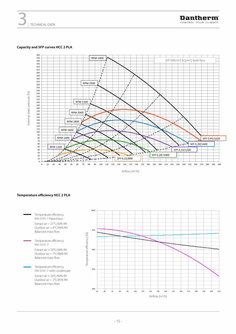
----- Temperature efficiency PassivHausExtract air = 21°C/30% RHOutdoor air = 4°C/94% RHBalanced mass flow
----- Temperature efficiencyEN13141-7 dryExtract air = 20°C/38% RHOutdoor air = 7°C/88% RHBalanced mass flow
----- Temperature efficiencyEN13141-7 humidExtract air = 20°C/60% RHOutdoor air = 2°C/85% RHBalanced mass flow
75,0
80,0
85,0
90,0
95,0
100,0
50 70 90 110 130 150 170 190 210
Tem
pera
ture
effic
ienc
y[%
]
Airflow [m3/h]
Temperature efficiency HCC2
Temperature efficiency EN13141-7 PassivHaus
Extract air = 21°C/30% RHOutdoor air = 4°C/94% RHBalanced mass flow
Temperature efficiency EN13141-7
Extract air = 20°C/38% RH Outdoor air = 7°C/88% RH Balanced mass flow
Temperature efficiency EN13141-7 with condensate
Extract air = 20°C/60% RH Outdoor air = 2°C/85% RH Balanced mass flow
Airflow [m3/h]
Tem
pera
ture
effi
cien
cy [%
]
80%
85%
90%
95%
100%
50 60 70 80 90 100 110 120 130 140 150 160 170 180 190 200 210
Tem
pera
turv
irkni
ngsg
rad
Flow [m3/h]
Capacity and SFP curves HCC 2 PLA
Exte
rnal
sta
tic p
ress
ure
[Pa]
Airflow [m3/h]
SFP [Wh/m3] & [j/m3], both fans
Temperature efficiency HCC 2 PLA

- 16 -
3TECHNICAL DATA
Capacity and SFP curves HCC 2E1
Temperature efficiency HCC 2E1
Exte
rnal
sta
tic p
ress
ure
[Pa]
Airflow [m3/h]
SFP [J/m3], for hele unit
Temperature efficiency EN 13141-7/dry
Outdoor air: 7°C/70% RH Extract air: 20°C/38% RHBalanced mass flow
Temperature efficiency EN13141-7 with condensate
Outdoor air: 2°C/88% RH Extract air: 20°C/60% RHBalanced mass flow
Airflow [m3/h]
Tem
pera
ture
effi
cien
cy [%
]
0
20
40
60
80
100
120
140
160
180
200
220
240
260
280
300
320
340
360
380
400
0 10 20 30 40 50 60 70 80 90 100 110 120 130 140 150 160 170 180 190 200 210 220 230 240 250 260 270 280 290 300
Pres
sure
[Pa]
Middle flow [m3/h]
RPM 2900
RPM 2700
RPM 2500
RPM 2200
RPM 2000
RPM 1800
RPM 1600
RPM 1400
SFP 0,45 / 1620
SFP 0,39 / 1400
SFP 0,33 /1200
SFP 0,28 / 1000
SFP 0,22 / 800
RPM 1200
SFP [Wh/m3] & [j/m3], both fans
40%
45%
50%
55%
60%
65%
70%
75%
80%
85%
90%
95%
100%
0 10 20 30 40 50 60 70 80 90 100 110 120 130 140 150 160 170 180 190 200 210 220 230 240 250
Effic
iency
Flow extract [m3/h]
40%
45%
50%
55%
60%
65%
70%
75%
80%
85%
90%
95%
100%
0 10 20 30 40 50 60 70 80 90 100 110 120 130 140 150 160 170 180 190 200 210 220 230 240 250
Effic
ienc
y
Flow extract [m3/h]

ACCESSORIES4
- 17 -
Wired control (HCP 10)Dantherm offers a prewired control unit, which is connected to the ventilation unit
with a 6 m cable. The wired control comes with a white plastic frame and a metal
frame for fastening into a standard junction box. Alternatively, Dantherm can supply a
box for fixing to the wall in an appropriate place.
The HCP 10 wired control gives the user the following possibilities :
▶ Manual control of air change (step 0-4)
▶ Control of air change with week program
▶ Demand controlled air change (if RH and VOC sensors are connected)
▶ Enable summer mode (only extract air)
▶ Enable manual bypass (requires an optional mechanical bypass to be mounted)
▶ Enable fireplace mode
▶ Reading and resetting of alarms, including filter alarm.
The wired HCP 10 control offers the possibility of adjusting the air volumes without
using Dantherm’s PC Tool.
Wireless remote control (HRC 3)Dantherm offers a wireless remote control, which can be mounted on the wall or
placed on a shelf. The remote control is designed for the user, but also includes a
special installer menu, allowing the installer to do extensive settings, without the use
of the PC Tool.
The remote control has a visual/acoustic alarm that will sound when the filter needs to
be inspected or replaced. This ensures correct maintenance even when the unit is set
to demand mode and your attention is not at the remote control.
The user features are:
▶ Fan speed in manual mode.
▶ Select demand mode (requires RH and/or VOC sensors to be mounted)
▶ Select week mode and week program 1-11.
▶ Manually activated bypass which closes again automatically.
▶ Enable fireplace boost mode. 7 minutes with overpressure inside the house for
easy ignition of a fireplace.
▶ Enable away mode in which the unit decreases permanently to speed 1
▶ Enable night mode in which the unit decreases to speed 1. The time night mode
can be adjusted.
▶ Remaining filter period + adjustment of same.
▶ Reading of temperatures in all four duct connections, including the remote
control’s embedded temperature sensor, as well as relative humidity and quality
of the extract air (accessory).
▶ Setting time and date.
ACCESSORIES
Wireless remote control
Wired control

- 18 -
4ACCESSORIES
Digital plug
External electrical preheating coil, 900 WThe electrical heating coil prevents ice building up in the heat exchanger at low
temperatures. The heating coil is mounted in the outdoor air duct. The heating coil is
connected to and controlled by the HCC 2 controller, which adjusts the heat output so
as to ensure an ice-free heat exchanger with the lowest possible energy consumption.
Pre-heat insulation kit for HCC 2This insulation kit is designed for fixing to the HCC 2 preheater. This customised
insulation kit protects against thermal bridges, condensation and excessive energy
consumption.
VOC air quality demand sensor (included in the Energy Efficiency Class A+ kit)The HCC 2 unit can be fitted with a VOC air quality sensor.
This sensor will continuously monitor the level of artificial as well as natural organic
fumes in the air. Examples of included fumes:
▶ Natural fumes, e.g. formaldehyde from building materials.
▶ Chemical fumes from sprays, e.g. hair spray or perfumes.
▶ Indoor pollution e.g. from smoking and printing with laser printer.
▶ Fumes from fire retardant substances in carpets, paint and furniture.
Using the VOC sensor in demand mode will result in the correct level of ventilation
with lowest possible electrical power consumption. If a wireless remote control is
connected, the actual VOC level will be shown in the display using a 3 level icon.
Digital plug (bag with 25 pcs.)This digital plug is connected to the control of the HCC 2 unit. This allows to override
the following :
▶ Fan speed 0, 1, 2, 3, 4
▶ Fire/smoke/negative pressure /stop + alarm
▶ High water level stop + alarm
Pre-heat insulation kit
VOC air quality demand sensor
External electrical preheating coil
ACCESSORIES4
- 19 -
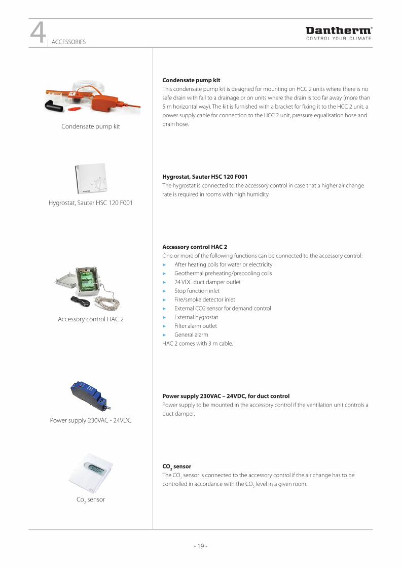
Condensate pump kitThis condensate pump kit is designed for mounting on HCC 2 units where there is no
safe drain with fall to a drainage or on units where the drain is too far away (more than
5 m horizontal way). The kit is furnished with a bracket for fixing it to the HCC 2 unit, a
power supply cable for connection to the HCC 2 unit, pressure equalisation hose and
drain hose.
Hygrostat, Sauter HSC 120 F001The hygrostat is connected to the accessory control in case that a higher air change
rate is required in rooms with high humidity.
Accessory control HAC 2One or more of the following functions can be connected to the accessory control:
▶ After heating coils for water or electricity
▶ Geothermal preheating/precooling coils
▶ 24 VDC duct damper outlet
▶ Stop function inlet
▶ Fire/smoke detector inlet
▶ External CO2 sensor for demand control
▶ External hygrostat
▶ Filter alarm outlet
▶ General alarm
HAC 2 comes with 3 m cable.
Power supply 230VAC – 24VDC, for duct controlPower supply to be mounted in the accessory control if the ventilation unit controls a
duct damper.
CO2 sensorThe CO
2 sensor is connected to the accessory control if the air change has to be
controlled in accordance with the CO2 level in a given room.
Accessory control HAC 2
Power supply 230VAC - 24VDC
Co2 sensor
Condensate pump kit
Hygrostat, Sauter HSC 120 F001

- 20 -
4ACCESSORIES
USB cable, 3 mUSB cable to be used in connection with software update of HCC 2 and Dantherm PC
Tool (HPT 1).
Calibration set (bag with 10 sets)This calibration kit contains 10 sets with each 3 m hose, two suction cups with hook
and two nipples. The kit is used for adjusting the HCC 2 air flows.
Dantherm PC ToolThe Dantherm PC Tool has an installer menu, where the installer can adjust the unit,
connect extra accessories, adjust various user settings, read and reset alarms, if any.
It also has a user menu, where the user can read and adjust various settings, such
as week programs, set points, alarms and historical data about temperatures and air
quality (accessory).
Fire Protection Controller (FPC)The Fire Protection Controller (FPC) is a unit that controls a fire damper for fire and
smoke protection purposes. The unit has been designed for Belimo or similar fire
damper actuators fitted with spring-return and position feedback. The fire damper
actuator is connected directly to the FPC, and then controlled via the ventilation
system. Each FPC is to be addressed individually. Up to four FPCs can be connected to
one ventilation unit.
The FPC is fitted with LED lamps indicating the damper position and status, and a
digital input socket for surveillance if so required in your installation, for instance for a
thermostat or a smoke detector.
Dantherm PC Tool
Calibration set
USB cable, 3 m
Fire Protection Controller (FPC)

- 21 -

- 22 -

- 23 -

Dantherm A/SMarienlystvej 65 | DK-7800 Skive Tel. +45 96 14 37 00 | Fax +45 96 14 38 [email protected] | www.dantherm.com
ABOUT THE DANTHERM GROUP
Control your climate
The Dantherm Group is a leading provider of climate control products and solutions. The group companies have more than 60 years of experience in designing and manufacturing high-quality and energy-efficient equipment for heating, cooling, drying and ventilation for a wide range of mobile and fixed applications.
Every year, Dantherm Group uses significant resources on product development to stay in the forefront and is constantly adapting the products to changing market demands and legislation.
The Dantherm Group has a number of strong brands with well-established market positions in the mobile, pool, commercial/industrial and residential markets.
Dantherm Group customers benefi t from our comprehensive knowledge base and the experience and expertise that we have gained from more than three million climate control products and solutions sold worldwide.
Global reach
The Dantherm Group is headquartered in Skive, Denmark and has companies in Norway, Sweden, United Kingdom, Germany, France, Switzerland, Italy, Spain, Poland, Russia, China and United Arab Emirates and a global distribution network.
In 2016 the Dantherm Group was acquired by the Swedish equity fund Procuritas Capital Investors V LP – a strong owner with the ambition to continue the development and growth of the company.
09.1
9
HCC
2 te
chni
cal i
nfor
mat
ion,
EN