
Færgeselskabet Læsø Tender Specification
230
Færgeselskabet Læsø Tender Specification 2017.0131.10 Date 16.05.18 Sign JFH
Transcript of Færgeselskabet Læsø Tender Specification

Færgeselskabet Læsø
Tender Specification
2017.0131.10
Date 16.05.18
Sign JFH
1
10 Design ‐ General ....................................................................................................................... 18
0100 Description & Principal Data ............................................................................................................ 18
0101 Intent ................................................................................................................................................ 18
0102 Principal Dimensions ........................................................................................................................ 19
0103 Deadweight & Draft ......................................................................................................................... 19
0104 Lightweight ....................................................................................................................................... 19
0105 Capacities ......................................................................................................................................... 20
0105‐01 Car Decks .......................................................................................................................................... 20
0105‐02 Tank Capacities ................................................................................................................................ 21
0107 Consumption and energy optimization ........................................................................................... 21
0108 Complement ..................................................................................................................................... 22
0109 General Arrangements/Description ................................................................................................. 22
0110 Rules & Regulations ......................................................................................................................... 23
0111 Class Notation .................................................................................................................................. 23
0112 Flag, Port of Registry ........................................................................................................................ 24
0113 National Rules & Regulations ........................................................................................................... 24
0114 International Rules & Regulations ................................................................................................... 25
0115 Special Rules & Regulations ............................................................................................................. 25
0115 – 1 Sea area ............................................................................................................................................ 25
0115 – 2 Dangerous Cargo .............................................................................................................................. 26
0116 Tonnage ............................................................................................................................................ 26
0117 Certificates ....................................................................................................................................... 26
0137‐1 Instruction books/documentation ................................................................................................... 27
0137‐2 ISM‐manual ...................................................................................................................................... 27
0137‐3 Decision support system for the Master .......................................................................................... 27
0137‐4 SOPEB manual .................................................................................................................................. 28
0137‐5 Cargo securing manual ..................................................................................................................... 28
0138 List of Manufacturers ....................................................................................................................... 28
0139 Calculations ...................................................................................................................................... 28
2
0140 Drawings........................................................................................................................................... 28
0146 "As Built" Drawings .......................................................................................................................... 28
0147 Drawings Exhibited on Board ........................................................................................................... 29
0150 Hull Requirements ........................................................................................................................... 30
0151 Hull Form .......................................................................................................................................... 30
0152 Model/CFD Tests .............................................................................................................................. 30
0156 Trim & Stability Requirements ......................................................................................................... 31
0157 Calculation of Noise ......................................................................................................................... 31
0170 Working Procedures ......................................................................................................................... 31
0172 Units of Measurements.................................................................................................................... 31
0173 Languages ......................................................................................................................................... 32
0174 Materials (see also 210) ................................................................................................................... 32
0175 Workmanship, QA ............................................................................................................................ 32
0178 Dry Docking ...................................................................................................................................... 33
0180 Trials, Tests & Delivery ..................................................................................................................... 33
0181 Tests of Materials, Components & Systems .................................................................................... 33
0182 Shop Trials ........................................................................................................................................ 33
0183 Dock Trials ........................................................................................................................................ 33
0184 Sea Trial, Speed & Endurance .......................................................................................................... 33
0185 Equipment Tests ............................................................................................................................... 34
0186 Inclining Test .................................................................................................................................... 34
0187 Noise & Vibration Test ..................................................................................................................... 35
0188 Cleaning for Delivery ........................................................................................................................ 35
0190 Miscellaneous .................................................................................................................................. 35
0191 Precautionary measures .................................................................................................................. 35
0194 Port & Terminal requirements ......................................................................................................... 35
0196 Crew Training ................................................................................................................................... 35
20 Hull Structural .......................................................................................................................... 37
0200 Scantlings & Class Drawings ............................................................................................................. 37
0201 Strength Requirements/Calculations ............................................................................................... 37
0202 Midship Section ................................................................................................................................ 37
3
0205 Bulkheads ......................................................................................................................................... 37
0206 Fore‐ and Aft End Structures ............................................................................................................ 38
0210 Materials & Methods ....................................................................................................................... 38
0212 Profiles ............................................................................................................................................. 38
0213 Chamfering and Cutting ................................................................................................................... 39
0214 Welding and Structural Details ........................................................................................................ 39
0215 Non‐steel Materials .......................................................................................................................... 40
0218 Structural Testing ............................................................................................................................. 40
0220 Bottom Construction ........................................................................................................................ 40
0221 Bottom, General ............................................................................................................................... 40
0222 Keel structure ................................................................................................................................... 41
0223 Floors and girders ............................................................................................................................. 41
0224 Double Bottom Tanks ....................................................................................................................... 41
0226 Peak Tanks ........................................................................................................................................ 41
0227 Heeling Tanks ................................................................................................................................... 41
0228 Fresh Water Tanks and Sewage Tanks ............................................................................................. 41
0229 Misc. Tanks ....................................................................................................................................... 42
0230 Shell Plating ...................................................................................................................................... 43
0231 Shell Plating, General ....................................................................................................................... 43
0232 Framing ............................................................................................................................................ 44
0233 Local Reinforcements ....................................................................................................................... 44
0235 Freeing Ports .................................................................................................................................... 44
0236 Bilge Keels ........................................................................................................................................ 44
0237 Fenders ............................................................................................................................................. 44
0238 Drain Plugs ....................................................................................................................................... 45
0239 Spray Rails ........................................................................................................................................ 45
0240 Bulkheads, Decks & Tanks ................................................................................................................ 46
0241 Bulkheads – General ........................................................................................................................ 46
0242 Decks ‐ General ................................................................................................................................ 46
0243 Flush Hatches ................................................................................................................................... 46
0245 Emergency Exits ............................................................................................................................... 46
4
0246 Local Reinforcement ........................................................................................................................ 46
0247 Splash Grids ...................................................................................................................................... 47
0250 Superstructures & Deck Houses ....................................................................................................... 47
0251 Superstructures ................................................................................................................................ 47
0253 Wheel House .................................................................................................................................... 47
0254 Decks ................................................................................................................................................ 48
0256 Accommodation Houses .................................................................................................................. 48
0258 Funnel ............................................................................................................................................... 48
0259‐1 Engine Casing ................................................................................................................................... 48
0259‐2 Trunk for Gas Vent Pipe ................................................................................................................... 48
0260 Foundations ..................................................................................................................................... 48
0261 Main Engine Foundations ................................................................................................................ 48
0263 Foundations for Deck Equipment .................................................................................................... 49
0266 Miscellaneous Foundations ............................................................................................................. 49
0270 Miscellaneous Steel Structures ........................................................................................................ 49
0271 Chain Lockers ................................................................................................................................... 49
0272 Hawse‐ & Chain Pipe & Anchor Pockets .......................................................................................... 50
0273 Sea Chests ........................................................................................................................................ 50
0276 Azimuth Thrusters ............................................................................................................................ 50
0290 Corrosion, Protection & Painting ..................................................................................................... 50
0291 General ............................................................................................................................................. 50
0292 Preparation of Surfaces .................................................................................................................... 52
0293 Paint Specification ............................................................................................................................ 53
0296 Cathodic Protection ......................................................................................................................... 55
0297 Hot Dip Galvanizing .......................................................................................................................... 56
30 Hull Outfit and Equipment ........................................................................................................ 58
0300 Hull Openings & Closures ................................................................................................................. 58
0301 Manholes with Covers ...................................................................................................................... 58
0302 Small Hatch Covers ........................................................................................................................... 58
0304 Exposed Access Doors ...................................................................................................................... 59
0304‐01 Weathertight Doors on Main Deck .................................................................................................. 59
5
0304‐02 Sliding Doors on Main Deck/Hoistable Deck .................................................................................... 59
0304‐03 Exterior Doors on Upper decks ........................................................................................................ 60
0305 Watertight Doors ............................................................................................................................. 60
0306 Port Holes & Windows ..................................................................................................................... 61
0306‐01 Windows, General ............................................................................................................................ 61
0306‐04 Windows on Passenger Deck ........................................................................................................... 61
0306‐05 Windows on Sun Deck ...................................................................................................................... 61
0306‐06 Wheel House Windows .................................................................................................................... 61
0306‐07 Skylight ............................................................................................................................................. 62
0306‐08 Glass Entrance Lobby and Shelters on Sundeck ................................................................................ 62
0307 Shell Doors ....................................................................................................................................... 62
0307‐1 Embarkation Doors .......................................................................................................................... 62
0307‐2 Doors for Bicycles ............................................................................................................................. 62
0307‐3 Side Doors ........................................................................................................................................ 63
0308 Engine Removal Hatches .................................................................................................................. 63
0310 Access & Protection ......................................................................................................................... 64
0312 Embarkation Ladders ....................................................................................................................... 64
0313 Stairs & Ladders ............................................................................................................................... 64
0314 Railings ............................................................................................................................................. 65
0316 Tarpaulins ......................................................................................................................................... 66
0317 Passenger Lifts .................................................................................................................................. 66
0320 Rigging & Deck Fittings ..................................................................................................................... 67
0321 Main Deck ........................................................................................................................................ 67
0322 Masts for signal lights, flags & radars .............................................................................................. 67
0330 Anchor & Mooring Arrangements ................................................................................................... 68
0331 Anchors & Anchor Chains ................................................................................................................. 68
0332 Anchor Winches & Chain Stoppers .................................................................................................. 68
0334 Mooring Winches ............................................................................................................................. 69
0335 Bollards, Hawseholes and Fairleads ................................................................................................. 69
0336 Rope Reels ........................................................................................................................................ 69
0337 Mooring Lines ................................................................................................................................... 70
6
0339 Automatic Mooring Arrangement / Equipment .............................................................................. 70
0350 Life Saving Equipment ...................................................................................................................... 70
0353 Life Rafts ........................................................................................................................................... 70
0353‐1 Marine Evacuation System (MES) .................................................................................................... 70
0353‐2 Additional Life rafts/slides for ambulance personnel and patients ................................................. 71
0354 Fast Rescue Boat/Means of rescue .................................................................................................. 71
0355 Miscellaneous Safety Equipment ..................................................................................................... 72
0357 Fast Rescue Boat Davit ..................................................................................................................... 72
0358 Escape Calculations .......................................................................................................................... 73
0360 Non Electric Navigational Equipment .............................................................................................. 73
0361 Magnetic Compass ........................................................................................................................... 73
0362 Clocks ............................................................................................................................................... 73
0363 Flags ................................................................................................................................................. 73
0364 Signal Equipment, Distress Signals ................................................................................................... 73
0366 Fog Bell ............................................................................................................................................. 74
0367 Megaphone ...................................................................................................................................... 74
0369 Other Instruments, Inclinometer ..................................................................................................... 74
0370 Marks & Identification ..................................................................................................................... 74
0371 Marks for In Water Survey notation ................................................................................................ 74
0372 Load Line, Draft Marks & Waterline Marks ..................................................................................... 74
0373 Letters of Registration, IMO‐No. and Tonnage ............................................................................... 74
0374 Name, Port of Registry ..................................................................................................................... 75
0375 Owners Marks, Bow Mark ................................................................................................................ 75
0376 Thruster Marks ................................................................................................................................. 75
0390 Miscellaneous Hull Equipment ........................................................................................................ 75
0393 Hull Fittings for Electronic Equipment ............................................................................................. 75
40 Accommodation ....................................................................................................................... 77
0400 Accommodation, General ................................................................................................................ 77
0401 Accommodation, General Requirements ........................................................................................ 77
0402 Design / Artist's Impressions ............................................................................................................ 78
0406 Structural Fire Protection ................................................................................................................. 78
7
0407 Sample Boards /Mock‐ups ............................................................................................................... 78
0408 Signage in Accommodation .............................................................................................................. 79
0410 Crew Accommodation ...................................................................................................................... 80
0411 Crew Accommodation Arrangement / Plans ................................................................................... 80
0412 Crew Relax Cabins ............................................................................................................................ 80
0413 Mess Room/Pantry .......................................................................................................................... 80
0414 Stairways and Corridors ................................................................................................................... 81
0415 Toilets, Bathrooms and Change Rooms ........................................................................................... 81
0416 Stowage for Life Jackets ................................................................................................................... 83
0417 Offices / Meeting Rooms ................................................................................................................. 83
0418 Crew Gymnasium ............................................................................................................................. 84
0420 Service Spaces .................................................................................................................................. 85
0421 Service Spaces Arrangement / Plans ................................................................................................ 85
0422 Wheel House .................................................................................................................................... 85
0423 Sick Bay/Ambulance room .............................................................................................................. 88
0424 Galley and Pantry ............................................................................................................................. 89
0425 Laundry and Drying Room – Deck 5 ................................................................................................. 92
0426 Stores– Deck 5 .................................................................................................................................. 93
0428 Cleaning Locker ................................................................................................................................ 93
0429 Garbage Stores ................................................................................................................................. 93
0430 Passenger Accommodation .............................................................................................................. 94
0431 Passenger Accommodation Arr. / Plans ........................................................................................... 94
0432 Passenger Cabins .............................................................................................................................. 94
0433 Lounges ............................................................................................................................................ 94
0434 Stairways, Corridors and Halls ......................................................................................................... 95
0435 Public Toilets .................................................................................................................................... 96
0438 Open Deck Areas, incl. Furniture ..................................................................................................... 98
0440 Furniture, Textiles and Decorations ................................................................................................. 98
0442 List of Materials ................................................................................................................................ 99
0443 Berths and Mattresses ..................................................................................................................... 99
0445 Tables ............................................................................................................................................... 99
8
0446 Sofas, Settees and Chairs ................................................................................................................. 99
0448 Curtains, Roller Blinds, Bedspreads ................................................................................................. 99
0450 Lights & Electrical Equipment ........................................................................................................ 100
0451 Low Locations Light Plans & Details ............................................................................................... 100
0452 Light Arrangement & Details .......................................................................................................... 100
0454 Furniture Light Arrangement ......................................................................................................... 100
0460 Deck Covering, Insulation, Joiner Work ......................................................................................... 100
0461 Deck Covering Plan ......................................................................................................................... 100
0462 Deck Covering ................................................................................................................................ 101
0464 Insulation Standards ...................................................................................................................... 101
0465 Insulation, Sundry .......................................................................................................................... 102
0469 Gratings .......................................................................................................................................... 102
0470 Walls, Linings and Ceiling ............................................................................................................... 102
0471 Walls and Linings ............................................................................................................................ 102
0472 Ceilings ........................................................................................................................................... 103
0473 Wall and Ceiling Standards, Wet Rooms ........................................................................................ 104
0474 Window Boxes................................................................................................................................ 104
0480 Accommodation Doors .................................................................................................................. 104
0481 Door Standards .............................................................................................................................. 104
0485 Locking System ............................................................................................................................... 105
0487 Internal Fire Doors ......................................................................................................................... 105
0490 Miscellaneous Accommodation ..................................................................................................... 106
0491 Decorative Signage Plans ............................................................................................................... 106
0494 Lifts Interior Arrangements ............................................................................................................ 106
0495 Waste and Garbage Handling Systems .......................................................................................... 106
0496 Lump Sums ..................................................................................................................................... 106
50 Hull Engineering & ‐ Piping Systems ........................................................................................ 108
0500 Ventilation (outside engine room) ................................................................................................. 108
0504 Ventilation of Car Deck .................................................................................................................. 108
0507 Ventilation Ducts, Grill & Intakes, .................................................................................................. 108
0510 Air Conditioning & Heating ............................................................................................................ 109
9
0511 Air Condition Requirements ........................................................................................................... 109
0512 Cooling Machinery for Air Con. ...................................................................................................... 111
0514 Air Handling Units .......................................................................................................................... 112
0515 Supply and return Systems ............................................................................................................ 113
0516 Exhaust Systems ............................................................................................................................. 114
0517 Separate Ventilation Unit ............................................................................................................... 114
0520 Hull Piping, General ........................................................................................................................ 114
0521 Design Requirements ..................................................................................................................... 114
0522 General limitations ......................................................................................................................... 115
0523 Materials, Piping ............................................................................................................................ 115
0524 Materials, Valves & Fittings............................................................................................................ 116
0525 Pipe Fittings and Supports ............................................................................................................. 116
0526 Pipe Insulation ................................................................................................................................ 117
0527 Pipe Protection ............................................................................................................................... 117
0530 Bilge‐, Heeling‐ & Drain Systems .................................................................................................... 117
0531 Heeling System ............................................................................................................................... 117
0534 Bilge System ................................................................................................................................... 118
0535 Daily Bilge & Oily Water System .................................................................................................... 120
0537 Drainage from Exposed Decks ....................................................................................................... 121
0538 Interior Deck Drainage & Gutters .................................................................................................. 122
0540 Air, Sound., Fill. & Heating Pipes .................................................................................................... 122
0541 Filling/emptying Pipes .................................................................................................................... 122
0543 Air‐ and Overflow Pipes for MGO System ..................................................................................... 124
0544 Air Pipes ......................................................................................................................................... 124
0545 Sounding Pipes ............................................................................................................................... 125
0546 Remote Sounding ........................................................................................................................... 125
0550 Service Piping ................................................................................................................................. 126
0551 Sanitary Water Supply System (Hot and Cold Water) .................................................................... 126
0555 Sewage System and Piping ............................................................................................................. 127
0557 Window Washing System .............................................................................................................. 129
0559 Provision Ref. System and Machinery ............................................................................................ 130
10
0560 Fire‐fighting .................................................................................................................................... 130
0561 System & Equipment Requirements .............................................................................................. 130
0562 Fire‐ and Safety Plan ...................................................................................................................... 130
0563 Fire Detection System .................................................................................................................... 130
0564 Portable Fire‐fighting Equipment ................................................................................................... 130
0564‐01 Fire Hoses ....................................................................................................................................... 130
0564‐02 Fireman’s Equipment ..................................................................................................................... 130
0564‐03 Emergency Escape Breathing Devices (EEBD) ................................................................................ 131
0564‐04 Portable fire extinguisher............................................................................................................... 131
0565 Fire & Deck Wash System .............................................................................................................. 131
0566 Water Mist Fire Extinguishing System for Accommodation .......................................................... 132
0567 Water Mist Fire Extinguishing System for Engine Rooms .............................................................. 133
0568 Local Protection Water Mist Fire System for Machinery ............................................................... 133
0569 Drencher System ............................................................................................................................ 134
60 Main‐ & Aux. Machinery ......................................................................................................... 137
0600 Machinery, General ........................................................................................................................ 137
0601 Machinery Requirements ............................................................................................................... 137
0602 Engine Room Arrangement ............................................................................................................ 137
0603 Design Conditions .......................................................................................................................... 138
0604 Machinery Tests ............................................................................................................................. 138
0607 Planned Maintenance .................................................................................................................... 138
0610 Prime Movers ................................................................................................................................. 139
0611 Propulsion Arrangement ................................................................................................................ 139
0612 Prime Mover for Power Generation. ............................................................................................. 139
0613 Prime Mover, Equipment ............................................................................................................... 140
0614 Fuel Requirement. .......................................................................................................................... 141
0618 Spare Parts and Tools ..................................................................................................................... 142
0620 Propulsion System .......................................................................................................................... 142
0626 Azimuth Propeller Units ................................................................................................................. 142
0627 Propeller Control Equipment ......................................................................................................... 143
0629 Spare Parts and Tools ..................................................................................................................... 144
11
0640 Auxiliary Boilers .............................................................................................................................. 144
0642 Oil Fired Central Heating Boiler ..................................................................................................... 144
0646 Exhaust Gas Boiler .......................................................................................................................... 145
0650 LNG System (Option 1 only) ........................................................................................................... 145
0651 LNG Storage System ....................................................................................................................... 145
0652 LNG Pipes ....................................................................................................................................... 146
0653 LNG Bunker Station ........................................................................................................................ 147
0660 Engine Room Outfit & Equipment ................................................................................................. 148
0662 Floor Plates, Platforms, Grating ..................................................................................................... 148
0664 Guards & Rails ................................................................................................................................ 148
0665 Insulation of Machinery ................................................................................................................. 149
0666 Drip Trays ....................................................................................................................................... 149
0667 Waste Containers ........................................................................................................................... 149
0670 Maintenance & Repair Facilities .................................................................................................... 149
0671 Workshop with Equipment ............................................................................................................ 149
0675 High Pressure Cleaning System ...................................................................................................... 150
0677 Lifting Gears and Transfer Arrangement ....................................................................................... 151
70 Machinery Systems ................................................................................................................. 154
0700 Markings & Identification .............................................................................................................. 154
0701 Tank Identification ......................................................................................................................... 154
0702 Pipe Colour Schedule ..................................................................................................................... 154
0703 Name Plates for Machinery ........................................................................................................... 154
0704 Label Plates for Valves & Fittings ................................................................................................... 154
0705 Label Plates on Operation Panels .................................................................................................. 155
0706 System Diagrams Mounted on Board ............................................................................................ 155
0710 Piping System, General Requirements ........................................................................................... 155
0711 Piping System Layout, General....................................................................................................... 155
0712 Piping Material ............................................................................................................................... 157
0713 Valves and Fittings Materials ......................................................................................................... 158
0714 Piping Connection & Support ......................................................................................................... 159
0715 Insulation of Pipes .......................................................................................................................... 159
12
0716 Protection of Pipes ......................................................................................................................... 160
0717 Valves, Quick Closing Device .......................................................................................................... 160
0718 Piping, Fittings & Valves ................................................................................................................. 160
0723 List of Engine Room Tanks ............................................................................................................. 161
0724 List of Pumps .................................................................................................................................. 162
0725 Filters and Strainers ....................................................................................................................... 163
0727 Tank Outfit ..................................................................................................................................... 163
0730 Ventilation for Engine Room .......................................................................................................... 163
0731 Natural Ventilation ......................................................................................................................... 163
0732 Mechanical Ventilation .................................................................................................................. 164
0733‐1 Gen. Set. Exhaust Gas System (OPTION 1) ..................................................................................... 166
0733‐2 Gen. Set. Exhaust SCR System (OPTION 2‐3) ................................................................................. 167
0733‐3 Waste Heat Recovery System ........................................................................................................ 167
0734 Exhaust Silencer for Gen Sets ........................................................................................................ 167
0735 Isolations of Gen Sets Exhaust Gas Pipes ....................................................................................... 168
0740 Cooling Water Systems ................................................................................................................. 168
0741 Water Cooling Systems, General .................................................................................................... 168
0742 Sea Inlets/Chest ............................................................................................................................. 169
0743 Overboard Discharges .................................................................................................................... 170
0745 Anti‐Fouling System ....................................................................................................................... 170
0746 FW Cooling System ......................................................................................................................... 171
0750 Fuel Oil Systems ............................................................................................................................. 173
0751 Fuel Oil System, General ................................................................................................................ 173
0752 Fuel Oil Supply Systems for Generator Set .................................................................................... 173
0756 MGO Bunker and Transfer System ................................................................................................. 174
0757 MGO Filtering System .................................................................................................................... 175
0760 Lubricating Oil System .................................................................................................................... 175
0761 Lub. Oil System for Generator Set ................................................................................................. 175
0763 Lubricating Oil / Hydraulic Oil / Gear Oil Transfer System ............................................................. 177
0764 Crankcase Ventilation .................................................................................................................... 178
0770 Compressed Air Systems ................................................................................................................ 178
13
0771 Starting Air System ......................................................................................................................... 179
0772 Working Air System ........................................................................................................................ 179
0773 Service Air System .......................................................................................................................... 180
0780 Heating System .............................................................................................................................. 181
0782 Central heating system .................................................................................................................. 181
0787 Heating coils for tanks outside Engine Room ................................................................................ 182
0790 Miscellaneous Systems .................................................................................................................. 182
0791 Gas Welding System ....................................................................................................................... 182
80 Electrical Machinery & Equipment .......................................................................................... 184
0800 General ........................................................................................................................................... 184
0801 Requirements for El‐Installation .................................................................................................... 184
0803 Design Conditions .......................................................................................................................... 185
0804 Testing of El‐Systems ..................................................................................................................... 185
0805 Instruments .................................................................................................................................... 185
0806 Electric Load Balance ..................................................................................................................... 185
0807 Name & Mark Signs ........................................................................................................................ 186
0808 El‐supply system ‐ Voltage ............................................................................................................. 186
0809 Explosion‐Proof Requirements ...................................................................................................... 186
0810 Electrical Power Supply .................................................................................................................. 187
0811 Main Generators – Power Supply .................................................................................................. 187
0813 Emergency Diesel Generator ......................................................................................................... 187
0815‐1 Shore Connection ‐ hotel load ....................................................................................................... 188
0815‐\ Shore Connection ‐ charging of battery bank (Optional) ............................................................... 188
0816‐1 Batteries (not including battery bank) ........................................................................................... 188
0816‐2 Batteries in battery bank for hybrid operation .............................................................................. 189
0818 UPS ................................................................................................................................................. 189
0820 Electrical Power Distribution ......................................................................................................... 190
0821 Main Switchboard .......................................................................................................................... 190
0822 Emergency Switchboard ................................................................................................................ 192
0823 Distribution Panels, Large consumers ............................................................................................ 193
0824 Distribution Panels, Lighting and small consumers ....................................................................... 194
14
0825 Transformers & Drives ................................................................................................................... 194
0826 Electric Cables, Installation ............................................................................................................ 194
082\ Breakers & Plug Sockets ................................................................................................................. 195
0830 Electrical Power Devices ................................................................................................................ 196
0831 Electrical Motors ............................................................................................................................ 196
0832 Motor Starters & Controllers ......................................................................................................... 196
0835 Electrical Heaters ........................................................................................................................... 196
0837 Main Propulsion Motors ................................................................................................................ 196
083\ Drives for Electric Propulsion ......................................................................................................... 196
0840 Electrical Lighting ........................................................................................................................... 197
0841 Lighting Fixtures ............................................................................................................................. 197
0842 Plug Sockets ................................................................................................................................... 199
0843 Navigation Lights ............................................................................................................................ 200
0847 Floodlights ...................................................................................................................................... 201
0848 Emergency Lighting ........................................................................................................................ 201
0850 Communication Equipment ........................................................................................................... 201
0851 GMDSS/Radio Equipment .............................................................................................................. 202
0852 Emergency Radio Equipment (SART/EPIRB/VDR) .......................................................................... 202
0854 Internal Communication ................................................................................................................ 203
0855 Communication & Command Systems .......................................................................................... 203
0860 Electrical Navigation Equipment .................................................................................................... 207
0861 Gyro Compass & Autopilot ............................................................................................................. 207
0862‐1 Echo Sounder ................................................................................................................................. 208
0862‐2 Anemometer .................................................................................................................................. 209
0863 Rudder Angle Indicator .................................................................................................................. 209
0864 Speed Log ....................................................................................................................................... 209
0866 Radar Equipment ........................................................................................................................... 209
0868 Satellite Navigation Equipment ..................................................................................................... 210
0869 Conning System .............................................................................................................................. 211
0870 Miscellaneous Electrical Equipment .............................................................................................. 211
Reefer Plugs ................................................................................................................................... 211
15
0876 Electrical Clock System ................................................................................................................... 211
0878 Electrical Ship's Whistle, Window Wiper ....................................................................................... 211
0881 Electrical Workshop ....................................................................................................................... 212
90 Automation ............................................................................................................................ 214
0920 Alarm and Monitoring System ....................................................................................................... 214
0921 Integrated Control, Alarm and Monitoring System (ICAM) ........................................................... 214
0922 Miscellaneous Alarm Systems ........................................................................................................ 218
0923 List of Alarms .................................................................................................................................. 218
0925 Burglary alarm System ................................................................................................................... 218
Dock alarm for Orskov Shipyard .................................................................................................... 218
0950 Automation of Ancillary Systems ................................................................................................... 218
0951 Sequential Restart of ancillary machinery ..................................................................................... 218
0953 Automatic start of standby pumps ................................................................................................ 219
0954 Fuel Oil Bunker and Transfer System (aut) .................................................................................... 219
0960 Automation of Auxiliary Systems ................................................................................................... 219
0961 Remote Controlled Valves .............................................................................................................. 219
0970 Safety System, Requirements ........................................................................................................ 220
0972 Fire Doors (indication & control) ................................................................................................... 220
0973 Watertight Doors and Bow visor etc. ............................................................................................. 220
0974 Fire dampers .................................................................................................................................. 220
0975 Fire Alarm System .......................................................................................................................... 221
0976 Gas Alarm System .......................................................................................................................... 221
0980 Miscellaneous Automation ............................................................................................................ 221
0983 Remote Sounding System .............................................................................................................. 222
0985 Draft Measuring ............................................................................................................................. 222
100 Cargo Handling ....................................................................................................................... 224
1000 Bow Visors, Car Stops and Hoistable Car Decks ............................................................................. 224
1001 General ........................................................................................................................................... 224
1013‐1 Bow/Stern Visor ............................................................................................................................. 225
1013‐2 Car Stops ........................................................................................................................................ 225
1015 Hoistable Car Deck ......................................................................................................................... 226
16
1018 Hydraulic System for Visor, car stops, hoistable deck, and winches ............................................. 227
Platform lift for engine stores ........................................................................................................ 228
17
10 Design General
170580.0131.01
Date 12.04.18
Sign JFH
18
10 Design ‐ General
0100 Description & Principal Data
0101 Intent
These specifications with attached G.A. plan and appendices describe a Ro‐Ro ferry to be built
primarily for the traffic from Frederikshavn to the island of Læsø, Kattegat, Denmark
The sailing schedule is classified as “day service” The specifications with attached G.A. plan shall
be understood as a description of the requirements of the Owners, giving operational
requirements to the vessel layout, manoeuvrability, vehicle deck, passenger flow and interaction
with shore facilities.
These specifications are to be read in conjunction with the Conditions of Contract, which
encompasses all legal aspects of the agreement such as:
interpretation
certificates
inspection
responsibility
deviations
trials/delivery
price, guarantees and instalments
liquidated damages
force majeure
insurance
warranty
arbitration
etc.
The Builders shall acquaint themselves with the project, carry out all calculations necessary and
take responsibility for fulfilment of the intent and requirements of these specifications.
Any item not specifically mentioned in the specifications, but required for the proper functioning
of the vessel, required by rules or authorities shall be supplied and installed by the Builder at no
cost to the owners.
For items or standards not mentioned in these specifications, a relevant, existing vessel shall be
pointed out mutually.
19
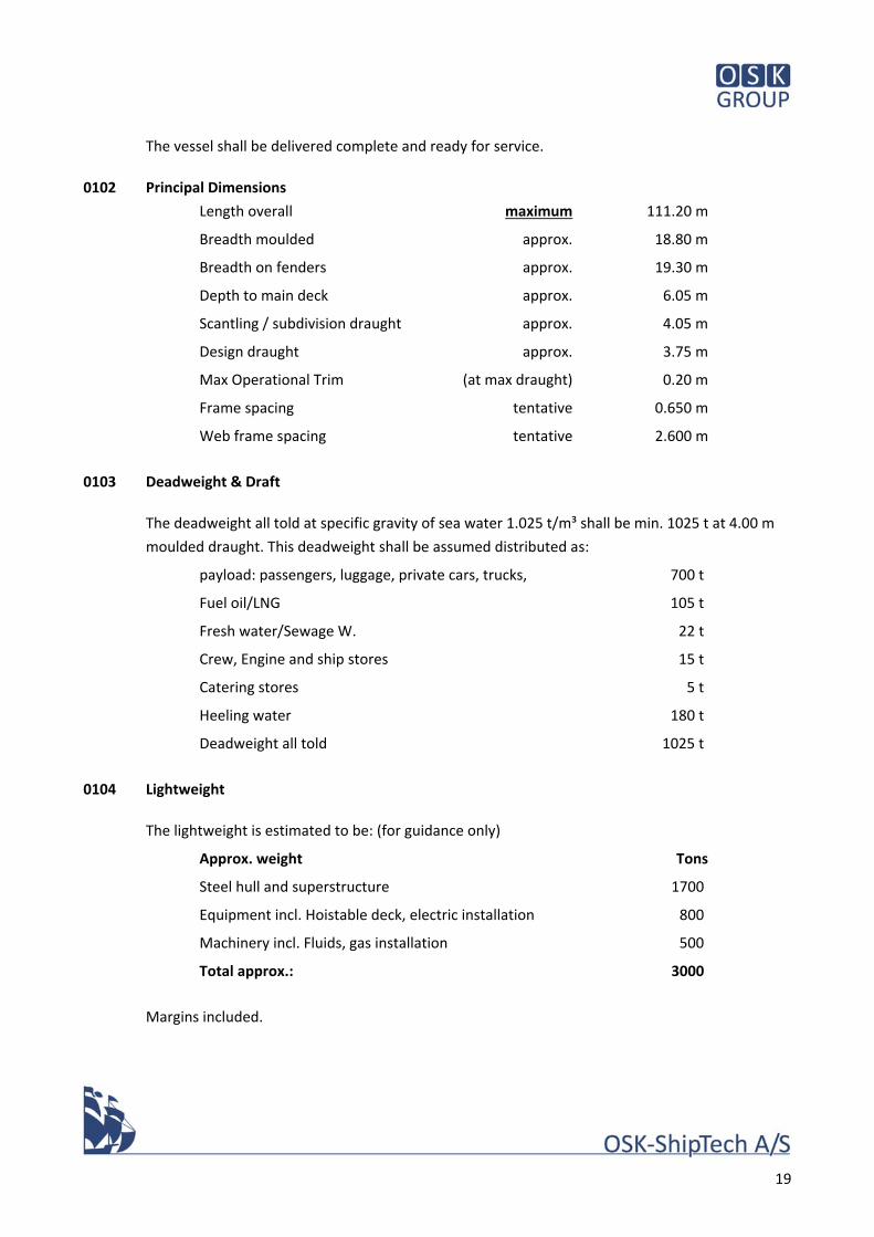
The vessel shall be delivered complete and ready for service.
0102 Principal Dimensions
Length overall maximum 111.20 m
Breadth moulded approx. 18.80 m
Breadth on fenders approx. 19.30 m
Depth to main deck approx. 6.05 m
Scantling / subdivision draught approx. 4.05 m
Design draught approx. 3.75 m
Max Operational Trim (at max draught) 0.20 m
Frame spacing tentative 0.650 m
Web frame spacing tentative 2.600 m
0103 Deadweight & Draft
The deadweight all told at specific gravity of sea water 1.025 t/m³ shall be min. 1025 t at 4.00 m
moulded draught. This deadweight shall be assumed distributed as:
payload: passengers, luggage, private cars, trucks, 700 t
Fuel oil/LNG 105 t
Fresh water/Sewage W. 22 t
Crew, Engine and ship stores 15 t
Catering stores 5 t
Heeling water 180 t
Deadweight all told 1025 t
0104 Lightweight
The lightweight is estimated to be: (for guidance only)
Approx. weight Tons
Steel hull and superstructure 1700
Equipment incl. Hoistable deck, electric installation 800
Machinery incl. Fluids, gas installation 500
Total approx.: 3000
Margins included.
20
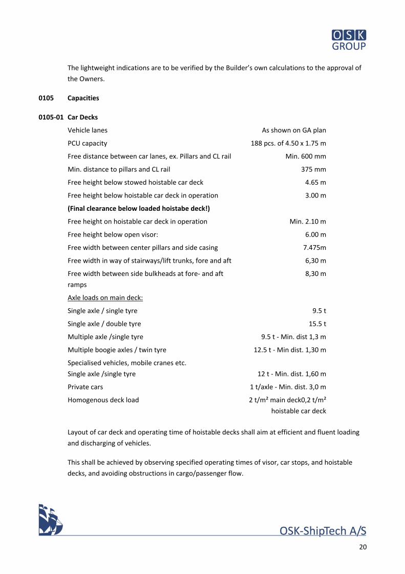
The lightweight indications are to be verified by the Builder’s own calculations to the approval of
the Owners.
0105 Capacities
0105‐01 Car Decks
Vehicle lanes As shown on GA plan
PCU capacity 188 pcs. of 4.50 x 1.75 m
Free distance between car lanes, ex. Pillars and CL rail Min. 600 mm
Min. distance to pillars and CL rail 375 mm
Free height below stowed hoistable car deck 4.65 m
Free height below hoistable car deck in operation
(Final clearance below loaded hoistabe deck!)
3.00 m
Free height on hoistable car deck in operation Min. 2.10 m
Free height below open visor: 6.00 m
Free width between center pillars and side casing 7.475m
Free width in way of stairways/lift trunks, fore and aft 6,30 m
Free width between side bulkheads at fore‐ and aft
ramps
8,30 m
Axle loads on main deck:
Single axle / single tyre
Single axle / double tyre
9.5 t
15.5 t
Multiple axle /single tyre 9.5 t ‐ Min. dist 1,3 m
Multiple boogie axles / twin tyre 12.5 t ‐ Min dist. 1,30 m
Specialised vehicles, mobile cranes etc.
Single axle /single tyre
12 t ‐ Min. dist. 1,60 m
Private cars 1 t/axle ‐ Min. dist. 3,0 m
Homogenous deck load 2 t/m² main deck0,2 t/m²
hoistable car deck
Layout of car deck and operating time of hoistable decks shall aim at efficient and fluent loading
and discharging of vehicles.
This shall be achieved by observing specified operating times of visor, car stops, and hoistable
decks, and avoiding obstructions in cargo/passenger flow.
21
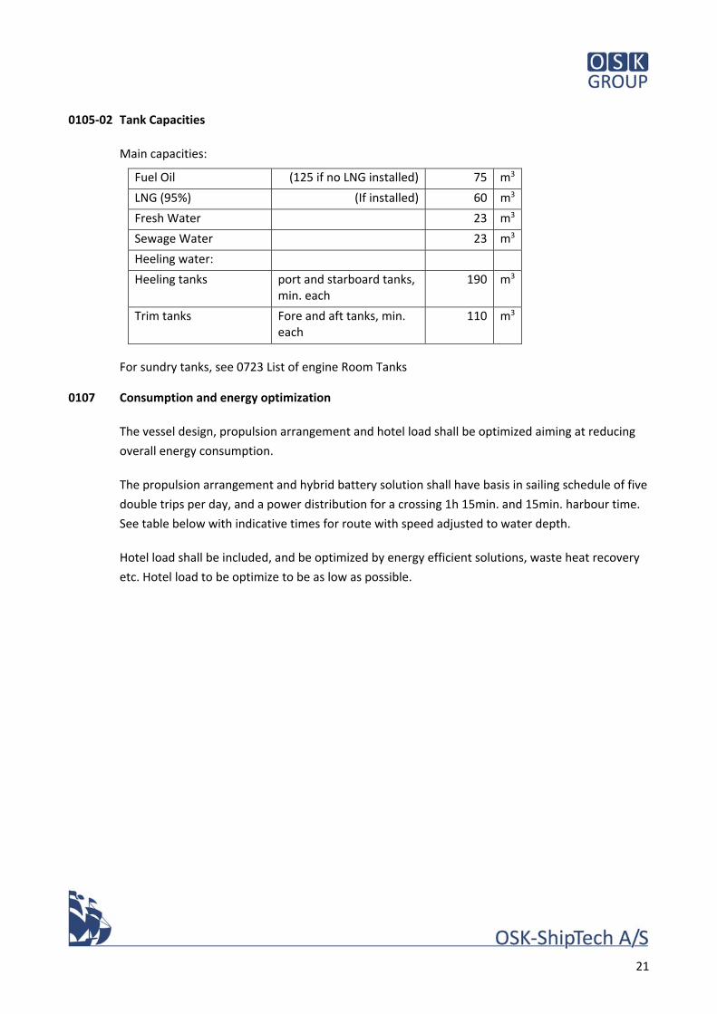
0105‐02 Tank Capacities
Main capacities:
Fuel Oil (125 if no LNG installed) 75 m3
LNG (95%) (If installed) 60 m3
Fresh Water 23 m3
Sewage Water 23 m3
Heeling water:
Heeling tanks port and starboard tanks, min. each
190 m3
Trim tanks Fore and aft tanks, min. each
110 m3
For sundry tanks, see 0723 List of engine Room Tanks
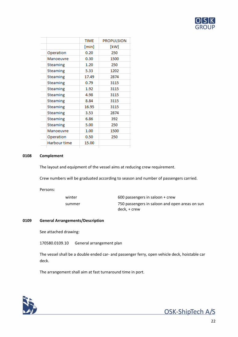
0107 Consumption and energy optimization
The vessel design, propulsion arrangement and hotel load shall be optimized aiming at reducing
overall energy consumption.
The propulsion arrangement and hybrid battery solution shall have basis in sailing schedule of five
double trips per day, and a power distribution for a crossing 1h 15min. and 15min. harbour time.
See table below with indicative times for route with speed adjusted to water depth.
Hotel load shall be included, and be optimized by energy efficient solutions, waste heat recovery
etc. Hotel load to be optimize to be as low as possible.
22
0108 Complement
The layout and equipment of the vessel aims at reducing crew requirement.
Crew numbers will be graduated according to season and number of passengers carried.
Persons:
winter 600 passengers in saloon + crew
summer 750 passengers in saloon and open areas on sun deck, + crew
0109 General Arrangements/Description
See attached drawing:
170580.0109.10 General arrangement plan
The vessel shall be a double ended car‐ and passenger ferry, open vehicle deck, hoistable car
deck.
The arrangement shall aim at fast turnaround time in port.
23
Propulsion: four (4) azimuth rudder propellers, electric driven from Diesel or Dual fuel LNG/MGO
generator sets, with battery packs for hybrid peak shaving or continuous battery operation . see
0612.
Passengers shall be carried in saloons on passenger deck (4), and open sun deck (5) .
Passengers are not intended to be allowed on car deck spaces during crossing, except ambulance
crew and patient.
Evacuation shall be from passenger saloon to MES‐system, accessible from both main vertical
zones.
Crew facilities shall be arranged in deckhouse above passenger saloon. No overnight crew
accommodation shall be provided, only cabins for rest during operation.
0110 Rules & Regulations
0111 Class Notation
The vessel will be assigned the following classification notations, according to DNV‐GL, Rules for
the Classification of Ships, Pt A, Ch 1, Sec 2 or equivalent notation from recognised classification
society to the approval of the Owner.
+1A1 Passenger/Car ferry B restricted area R2
E0
Gas Fuelled (if applicable)
ICE CLASS C
BIS
Rules for battery safety and battery Power
The classification notations have the following meaning:
+1A1 The vessel is built and has been surveyed during construction in accordance with the
requirements of the Rules and maintained in a condition considered satisfactory by the Society.
Passenger/Car ferry B ro/ro ship for passengers and vehicles, cars on open deck only
Restricted Area R2 distance from nearest port or safe anchorage 50 nm winter/
100 nm summer (maximum area for open ferry)
ICE CLASS C basic ice strengthening according to DnV rules
24
E0 The ship is fitted with automated installations enabling machinery spaces to remain
periodically unattended in all sailing conditions including manoeuvring.
Gas Fuelled gas engine installations on board
BIS in water survey
0112 Flag, Port of Registry
Danish
Port of registry: Vesterø
0113 National Rules & Regulations
The vessel shall be built to fulfil all applicable rules and regulations of the Danish Maritime
Authorities including the following:
“Meddelelser fra Søfartsstyrelsen D, teknisk forskrift for skibes bygning og
udstyr m.v., passagerskibe i national fart”
based on European Community Directive 2009/45/EU, with national
interpretations and supplements, hereafter referred to as DMA Notice “D”.
The vessel shall be built, equipped, and approved for Sea area "B"
DMA Notice “A” concerning working environment, including noise level
Resolution MSC.285(86) Guidelines on Safety for Natural Gas‐Fuelled Engine
Installations in Ships, or DNV rules for gas fuelled ships, as may be deemed
applicable by the Danish Maritime Authorities.
Guidelines concerning facilities for the disabled, “Rederiernes Standard for
Tilgængelighed på Passagerskibe” SBI 2014:17.
COLREG
International Loadline Convention 1966 incl. supplements
International Electrotechnical Commission (IEC) in particular publication 92
International Tonnage Measurement of Ships 1969
25
Marine Equipment Directive ‐ 96/98/EC and later amendments
MARPOL (SOX, NOX)
DMA technical notice on transport of vehicles
DMA technical notice on marking of Helicopter‐pickup area
Calculation of escape ways and evacuation time shall be carried out at an early
stage of detailed design
Prediction of noise level shall be carried out at an early stage of detailed design
Certificate from relevant Danish authorities allowing food handling on board in
galley, pantry/scullery and stores
Standard of subdivision shall be in accordance with probabilistic damage
stability calculation. See also 0156. Main watertight bulkheads shall be spaced
allowing for lengthening of the vessel by 20m.
It is the responsibility of the Builder to ensure fulfilment of all applicable rules and regulations of
DMA and other relevant Authorities, also to the extent that fulfilment necessitates changes in
these specifications.
Class approvals and certificates as required.
Any other applicable Danish legislation incl. latest amendments
The owners shall apply for waiver from DMA for the following:
overnight accommodation facilities for crew
treatment plant for sewage water and oily water
0114 International Rules & Regulations
All materials and components required to be type approved shall be supplied with the EU‐"wheel
mark" and MED‐certificate within the framework of the EU‐directive on marine equipment
0115 Special Rules & Regulations
0115 – 1 Sea area
The route Frederikshavn – Vesterø is classified as sea area “B”
26
Significant wave height according to Stockholm Agreement is 1,5m
0115 – 2 Dangerous Cargo
Permit for carrying dangerous cargo in limited quantities according to DMA/Baltic Convention.
The vehicle deck is to be classified as “open Deck” with respect to dangerous cargo.
Considered cargoes:
Petrol, diesel fuel, ethanol in tank truck and/or IBC container
Propane/butane, Oxygen/acethylen gas in cylinders on truck or crate pallet
Misc. Hazardous substances/items for private use in small quantities such as firearm
ammunition, fireworks
Household and agricultural chemical commodities
paint
Stowage of trucks with pressed straw or wood chips (bio‐fuel) below superstructure deck.
0116 Tonnage
Vessel to be measured in accordance with 1969 Convention.
The tonnage is preliminarily estimated to be 5150 GT (for guidance only)
0117 Certificates
Builder’s certificate
Bill of sale
Certificate of Nationality
Passenger safety certificate
IAPP
ISPP
EIAPP
AFC
Class Certificate (hull and machinery)
Radio Certificate
Load Line Certificate
Tonnage Certificate
Certificate of safe manning (Owners)
“Asbestos free” certificate
Certificate of lifting appliances
Certificate for food handling in Kiosk and kiosk stores
27
Any other certificates which may be required by the Danish Maritime Administration or other
relevant authority.
0137‐1 Instruction books/documentation
For all items of machinery and equipment, types of materials in accommodation, insulation, paint
etc. full documentation to be supplied in a database form, enabling materials used in construction
of the vessel to be identified in case of later repairs, service and maintenance.
Spec number system to be used for organizing the files.
Information shall for each item at minimum cover:
Maker and type number, serial number
Maker's or agent's contact details
Instruction booklets for installation and maintenance
Service intervals
Spare part lists
Certificate
Drawings and diagrams
List of inventory or scope of supply from the respective supplier
Letter of warranty from respective supplier
The information shall be supplied in a commonly readable and editable data format, and three
hard copies organized in binders.
The crew must have full and unlimited right to access all ICAM, PLC and similar, to make the
necessary adjustment. See also 1001 and 0921.
0137‐2 ISM‐manual
The Builder shall supply template for ISM‐manual. The template shall be based on a reasonably
simple form, to approval by DMA.
The Builder shall fill in such data requiring input from Builder.
0137‐3 Decision support system for the Master
Necessary information, plans, instructions to be compiled in a book, plans to be displayed in
Wheel House, as required by DMA notice “D”, rule 29.
28
0137‐4 SOPEB manual
The Builder shall supply SOPEB manual with all relevant information, bunkering instructions etc.
Owners shall complete the manual by filling in contact details of the responsible local authorities
and emergency response contact points.
0137‐5 Cargo securing manual
Builder to supply cargo securing manual, in particular for trucks of every kind, heavy vehicles such
as construction machinery and mobile cranes.
Motor bikes to be included.
0138 List of Manufacturers
Where manufacturers or trade names are mentioned in the following, they shall be understood
merely as descriptions of types or level of quality required.
Make and type of equipment shall be approved by the Owner.
Makers list for all major components to be presented to the Owner for approval within two
months from effectiveness of the contract.
0139 Calculations
All necessary calculations for class and statutory regulations, weight etc. to be supplied by the
shipyard, including:
Detailed weight calculation incl. COG, to be kept updated during all phases of construction and “as‐built”
trim and stability incl. loading/discharging
damage stability
structural analysis and vibration calculation of superstructure
prediction of noise level in passenger and crew accommodation, Wheel House, public spaces including open decks
external noise/ compliance with environmental requirements to be predicted
torsional vibration analysis of engine/shafting systems
evacuation analysis (IMO MSC Circ. 1533)
0140 Drawings
0146 "As Built" Drawings
All drawings, diagrams, specifications to be supplied with the vessel to be amended "As Built".
29
All drawings, plans and diagrams also to be supplied in AutoCAD electronic format, as well as in
three paper copies filed in binders.
To be supplied:
G.A.
Class drawings
Steel construction plans (detailed)
Engine/propulsion/shafting drawings
Engine room arrangement
Deck arrangement
Mooring arrangement
Car deck arrangement
Berthing plan/interface with ferry berth and ramps
Fender arrangement
Arrangement in Wheel House
Structural fire protection plans
Joiner plans
Piping diagrams
Detailed docking plan, incl. position of anodes, hull marks and paint lines
Capacity / Tank plan, Sounding tables
Masts
Navigation light arrangement plan
Electric distribution plans and system documentation
Stability information including Damage Control Plan
Trim and clearances during loading/discharging of cargo.
Fire‐fighting and Life‐saving appliances plans
Damage control‐ and watertight integrity plan acc. to DMA Notice “D” (referring to SOLAS Ch. II‐1 reg. 23/IMO Circ. 919)
Compartment numbering plan (at early stage to the approval of the Owners)
All the above listed paper formats are to be supplied in three copies filed in binders.
0147 Drawings Exhibited on Board
All required instructions, notices etc. are to be framed and displayed.
System drawings to be laminated in plastic, framed and displayed in the engine room.
Fluorescent escape route plans to be displayed on the inside of all cabin doors, in day‐room and
service spaces, doors of escape routes etc.
30
Fire Safety Plan, Life Saving Appliances Plan, Damage control plan to be laminated in plastic in
suitable scale and stored in holder in Wheel House.
F.F.A.‐ and L.S.A.‐plans to be displayed in Dayroom and in passenger area.
F.F.A.‐ plan laminated and stored in box at side doors and entrances to satisfaction of DMA and
Owners.
0150 Hull Requirements
0151 Hull Form
Double ended, round bilge, V‐shaped ends with bulbous bow, two (2) Azimuth propeller units
either end.
The shape of the upper side shall be continued into the bow and stern visor.
Waterline shape and flare shall ensure good performance in rough, short sea as encountered on
the route.
Fins for course stability shall be fitted in centre line below bulb and/or as side fins outside/toward
midship of the azimuth units (pectoral fins). Fins for course stability shall be double symmetric
elliptical cross section. If Planar Motion Mechanism test proves sufficient course stability for
steering with autopilot or manual steering, without excessive rudder action, it may be considered
not to fit fins. See also 0184
0152 Model/CFD Tests
Model tests shall be carried out at a recognized model test institute with proven experience in
double ended ferries.
Minimum scope
CFD calculations of ship flow, for optimisation of shape prior to model production.
resistance
self‐propulsion
wake field measurement for propellers
Planar Motion Mechanism test (PMM), providing data for prediction/calculation of course stability, zigzag test and spiral test at varying speed, and data for manoeuvre simulation (crew training)
manoeuvre test
DP‐diagram to be provided
The vessel shall be able of station keeping at 20m/sec. steady side wind.
31
It is expected that above tests (resistance, waves and PMM) can be carried out with the ship
model in one scale.
The model tests shall be carried out at a design draught of 3,75 m, corresponding to an average
loading condition.
Sea trials at final delivery to be performed at the same draught as model tests.
0156 Trim & Stability Requirements
The vessel shall comply with DMA/EU‐directive for domestic service requirements for intact and
damage stability for the sea areas as specified under 0115 above.
SOLAS rules for probabilistic damage stability shall be applied.
Stockholm convention shall apply for wave height 1.5m in area
The Builder shall carry out intact and damage stability calculations, including calculation of trim
during loading/discharging, as soon as the lightweight and centre of gravity have been calculated.
Calculation shall be submitted latest 2 months after contract, calculation of weight and centre of
gravity shall be updated and submitted to owners monthly until final inclining experiment.
All relevant full and part load conditions are to be included, reflecting the operational pattern of
the vessel.
The Builder’s preliminary calculations are to be approved by DMA and the Owners.
Damage Control Plan to be provided showing the consequences of flooding of any compartment
or combination of compartments with colour code bar, informing also the resulting freeboard,
GM, heel and trim.
0157 Calculation of Noise
Prediction of noise level to be carried out to ensure compliance with DMA requirements to noise
level, as well as environmental requirements in harbour and when berthing.
0170 Working Procedures
0172 Units of Measurements
All measurements shall be in metric units.
32
0173 Languages
All documentation, drawings, instruction manuals etc. shall be in English.
All instructions meant for passengers, as well as main drawings displayed on board shall also be in
Danish.
All signs, nameplates etc. in crew area to be in Danish. Plan to be approved by Owner.
All signs, nameplates etc. in passenger area to be in Danish & English. Plan to be approved by
Owner.
0174 Materials (see also 210)
All material shall be new and suitable for use in a marine environment. Due consideration shall be
given to durability and low maintenance. All fittings and equipment shall have been produced for
marine use.
The Builder shall be obliged to use the lightest commercially available alternative of material,
construction or component in order to keep the lightweight of the vessel as low as practical.
Detailed notes to this effect in the following are to be strictly observed.
0175 Workmanship, QA
Workmanship shall be of first class quality and in accordance with best shipbuilding practice.
The yard shall implement its QA system during the construction period and incorporate remarks
from class, authorities and owners.
The yard shall continuously survey and record block alignment, keel‐ and deck straightness,
alignment of shafts, visor and ramps, rudder propellers, finns, skeg, bilge keels etc. to ensure
correct positioning of such items.
Draught marks to be positioned using survey instruments and be based on a measured mean keel
line.
Survey of keel line, and positioning of draught marks shall be carried out in presence of owners
representative and class.
3‐D scan to be performed as documentation of underwater hull, including draught marks, during
final docking.
33
0178 Dry Docking
Prior to sea trials, the vessel shall be dry docked, cleaned and painted with the final coats of paint.
0180 Trials, Tests & Delivery
0181 Tests of Materials, Components & Systems
Extent, programme and duration of Dock trials, Sea trials and operational trials to be approved by
the Danish Maritime Authorities, the classification society and the Owners and as described in
Conditions of Contract.
Trial programmes to be forwarded for approval two weeks prior to trials, sheets shall be prepared
for each test and component.
The Builder shall appoint a designated person, qualified to conduct and record all tests and trials.
Data record from VDR shall be stored and supplied to Owners in common readable format.
All costs in connection with trials are to be for Builder’s account unless otherwise agreed.
The Yard shall arrange five (5) days training in a simulator for the Crew. All costs is for Builder’s
account unless otherwise agreed.
0182 Shop Trials
To the satisfaction of Class and DMA. The Owners may attend at their discretion.
0183 Dock Trials
To the satisfaction of Class, DMA and owners.
0184 Sea Trial, Speed & Endurance
During trials, a speed of 17,1 knots shall be achieved at a mean draught of 3,75m corresponding
to an average loading condition with deadweight 686t assumed to be distributed as follows:
payload: passengers, luggage, private cars, trucks, 352 t
Fuel oil/LNG 96 t
Fresh water/sewage water 24 t
Crew and stores 16 t
Heeling water 198 t
34
Deadweight in sea trial condition 685 t
The required draught of 3,75 meter, may be obtained by temporarily using the void tanks as
ballast tanks (fresh water only)
Speed trials to be carried out as double runs in deep water max. 2 Bft, calm sea. Speed range for
trials: 60% ‐ 80% ‐ 100% MCR.
Engine data to be recorded during speed trial.
Speed trials at final delivery to be performed at the same draught as model tests.
Crash stop and turning circle, zigzag test to be carried out at 100% and 80% MCR.
Turning circle tests shall be carried out for helm angles 10°, 15°, 20°, and 25°.
Result of turning circle and crash stop tests shall be presented as diagrams for display in Wheel
House.
The vessel shall be able to carry out any number of zigzags in succession. These may be 15°/1°
tests (Helm angle 15, change of heading 1 degree)
Crabbing test, transverse speed to be obtained corresponding to 20m/sec. side wind.
During sea trials in the vicinity of builder’s yard, vibrations shall be observed at service speed at
water depths resembling depths on the envisaged route of the vessel between Frederikshavn and
Vesterø.
0185 Equipment Tests
A trial shall be performed to ensure proper interaction between the vessel and shore systems, in
the ports of Frederikshavn and Vesterø. Loading and discharging shall be tested with a full load
consisting of aggregate and articulate trucks, private cars of mixed average size on main deck and
on hoistable car deck, and trolleys for goods, bicycles etc. Loading/discharge of passengers
including disabled persons in wheelchairs to be tested at side embarkation doors.
Loading and discharging to be tested in both Frederikshavn and Vesterø.
Vehicles etc. for test will be arranged by the Owners.
0186 Inclining Test
On completion of the vessel, the Builder shall carry out an inclining experiment under survey of
DMA/Class and the Owner´s surveyors and re‐calculate intact and damage stability.
35
0187 Noise & Vibration Test
Sound level measurement to be carried out acc. to DMA‐requirements during sea trials.
Further, measurements of environmental noise to be carried out with ferry in berth,
loading/discharging condition with one gen. set and vent. fans etc. running.
0188 Cleaning for Delivery
The vessel shall be delivered clean in every respect, including hull below waterline and box
coolers. Final cleaning report for Owners approval.
0190 Miscellaneous
0191 Precautionary measures
During construction, all material is to be suitably protected against weather, fire, theft etc.
The yard shall keep the vessel under surveillance/fire watch during all stages of construction until
final delivery.
0194 Port & Terminal requirements
During design and construction, the Builder shall cooperate closely with the contractors building
the ferry berths and shore facilities at Frederikshavn and Vesterø to ensure proper interaction
between the vessel and berth, ramps, gangways and mooring arrangement.
Location of bunker station, filling of fresh water, discharging of sewage water, sludge etc. and
shore power connection to be agreed with owners and contractors for harbour construction.
Online webcam for monitoring the building process 24/7/365 to be mounted on the Yard and
Time lapse video of the entire building process to be supplied to the Owner.
0196 Crew Training
The builder shall include familiarisation and training of crew.
In particular, training in operation of gas fueled ships shall be carried out, divided into following
categories:
Category A – Basic training for basic safety crew, min six (6) persons one day
Category B – Supplementary training for deck officers, min three (3) persons two days
Category C – Supplementary training for engine officers, min three (3) persons two days
Three (3) scale models (1:100) in transparent case to be delivered.
36
20 Hull Structural
170580.0131.01
Date 24.01.18
Sign MPA
37
20 Hull Structural
0200 Scantlings & Class Drawings
0201 Strength Requirements/Calculations
Structural strength calculations to be carried out by the Builder in accordance with Class
requirements.
Scantlings shall be calculated aiming at minimising weight. Specified minimum thickness to be
observed including required corrosion addition.
Ice Class shall be achieved by increased plating thickness in ice belt region with introduction of
intermediate frames and a system of supporting stringers and web frames. Distribution of ice
frames, stringers and webs shall be calculated aiming at minimising weight.
0202 Midship Section
Deck heights (for guidance):
Inner bottom, deck 1 1,750/1,975/2,200/2,425 mm ab BL
Main Deck (Car deck), deck 2 6,050 mm ab BL, amidships
Side Deck (Car deck), deck 3 9,425 mm ab BL
Passenger Deck, deck 4 11,950 mm ab BL
Sun Deck, deck 5 14,950 mm ab BL
Top of Acc. House, deck 6 17,550 mm ab BL
Wheel House steel floor, deck 7 19,385 mm ab BL
Wheel House top 22,295 mm ab BL, in CL
0205 Bulkheads
The vessel shall be subdivided into thirteen (13) watertight compartments with ten (10)
watertight doors, and with two (2) main longitudinal bulkheads for side casings on deck 2 and 3,
as shown on the General Arrangement.
38
On main deck approx. fr. 30 sb side, one (1) watertight door to be fitted between the car deck and
the lift room ‐ see 1031.
0206 Fore‐ and Aft End Structures
The end structures with heavy stern frames and foundations to accommodate the azimuth
thrusters are to be designed in such a way that the operation of the thrusters does not cause
excessive vibrations.
Arrangement of internal webs and bulkheads are to be specially considered to minimize vibration.
Eye plates shall be provided for lifting of the Thrusters.
Access to all areas of all tanks is to be provided.
Exterior appendages required for thruster’s installation are to be streamlined. Fixed fins for
increased course stability are to be installed ‐ see 0151.
0210 Materials & Methods
High tensile steel shall be used for plates, profiles and built‐up girders in order to save weight
where appropriate. Remaining steel to be mild steel.
Vehicle lanes on Main Deck shall be high tensile steel NV36 in order to save weight and increase
resistance to rolling down of plates under wheel load.
Bottom and shell plating to be high tensile steel NV36.
In superstructures, high tensile steel may be used for weight saving.
0212 Profiles
Profiles in hull and superstructures to be bulb profiles, flat bars and built‐up girders. Weight
saving shall be considered.
Cargo Decks from Deck 2 – Deck 4 will be divided in centre line by pillars from frame (‐56) to
frame (56) for support of the Passenger Deck.
In order to save space in Side casings, angle bar stiffeners shall be used.
39
0213 Chamfering and Cutting
All sharp edges of any steel plate and cut‐out like manholes, limber holes, stiffeners, passages,
manual weld beads, scallops etc. are to be rounded by 3‐pass grinding to min. R = 2.0 mm to
ensure a proper adhesion of paint.
0214 Welding and Structural Details
Double continuous welding to be applied to all hull structures, cargo areas, ventilation ducts
integrated in hull structures, chain lockers, wet rooms, steel surrounding bathrooms, toilets and
laundries, steel bulkheads in galleys and pantries, and to all constructions exposed to the
weather.
Welding of dry spaces in superstructures shall be chain intermittent or staggered welding in order
to reduce welding deformation.
When joining members with difference in thickness exceeding three (3) mm, the thicker plate
edge to be chamfered at least 1:3.
All welding spatters to be removed carefully and welding seams to be brushed after completion.
Welding procedures shall aim a low heat input to minimize deformation. Fairing by heat shall be
done with low heat input and minimum of quenching.
In order to achieve a good shipbuilding appearance special care to be taken for good alignment
and evenness of plates. Overall fairness of exterior surfaces of hull, superstructures, houses,
funnels and bulwarks shall be within 4 mm deviation from a straight line/batten per frame spacing
after completion of welding, hot work and fairing. No filler material must be used to achieve this
fairness.
Holes for air, drainage, access and lightening to be provided in all structural non‐tight areas, tanks,
voids and bilges, wherever the cutting of such holes is necessary or practicable without disturbing
the structural strength of the members. Corners of all openings and free plate edges to be grinded
acc. to item 0213, and no visible sharp edges are to be remaining.
Drainage holes for water and oil to be provided at suitable positions in all foundations.
If aluminium is used in the construction, joining of steel and aluminium structures shall be by
means of compound metal bars.
40
If nothing else is mentioned in this Specification, or on drawings approved by the Owner, IACS
standard is in general accepted, except for visible outer decks and sides, where the IACS
“standard” value should apply as a “limit” value.
0215 Non‐steel Materials
Stainless steel (SS) to be EN Number 1.4404 or better.
Aluminium alloy shall be 5083 for plates and 6082 for profiles.
Production facilities for stainless steel and aluminium alloy shall be separate from steel
production and be protected from direct and airborne contamination such as oil, dust, soot,
welding fumes and grinding particles of steel, sparks etc.
Tools shall be approved for the specific material and shall not be used for other materials and/or
purposes.
Scaffolding and ladders of steel shall not be used for aluminium constructions.
Aluminium shall be stored in dry conditions with air between the plates/profiles to avoid
corrosion.
Synthetic material may be used where appropriate, provided approval from Class, DMA and
Owner.
0218 Structural Testing
X‐ray and/or ultrasonic tests for welds are to be carried out in compliance with the requirements
of Class and as agreed with Owner’s representative.
Pressure tests of tanks and systems to be carried out prior to painting acc. to Class requirements
and to approval by Class and Owner.
0220 Bottom Construction
0221 Bottom, General
Keel plate to be reinforced for load during dry‐docking.
41
0222 Keel structure
One (1) longitudinal CL girder to be fitted on the flat keel plate with docking brackets acc. to
Rules.
The flat bottom centre keel is to continue into a streamlined centre skeg at both ends ‐ ending at
frame (‐60) and frame (+60).
Where the skeg forms a separate watertight volume below shell plating, it shall be divided
corresponding to subdivision of hull above.
0223 Floors and girders
Bottom and inner bottom to be longitudinally stiffened with transverse floors at every fourth
(4th) frame in general and at every second (2nd) frame within the Engine Rooms.
Air and drain holes to be provided in the bottom floor, longitudinal girders and longitudinal
frames in sufficient numbers.
All open floor plates, and non‐watertight girders, inside tanks are to be provided with drain holes
at upper and lower edges to secure an easy flow of liquids to the suction pipes.
0224 Double Bottom Tanks
Easy access inside double bottom spaces to be ensured by big access holes with stiffened edges.
Holes within each tank to be aligned.
0226 Peak Tanks
Aft and forward peak tanks shall be utilized as trim tanks.
0227 Heeling Tanks
One (1) pair of ballast tanks in SB and PS amidships, shall be utilized as heeling tanks.
0228 Fresh Water Tanks and Sewage Tanks
Fresh Water Tanks
Two (2) FW Tanks shall be built of EN Number 1.4404 above inner bottom as shown on General
Arrangement. Stiffening shall be on the outside. The dividing bulkhead between the two tanks
shall be corrugated. Top of tank app. 700 mm below car deck.
The internal surface is to be smooth and free of welding splatters. Weld seams and other affected
areas are to be grinded smooth with a disc sander and/or a belt sander.
42
Sewage Tanks
Two (2) Sewage Tanks shall be built of EN Number 1.4404 above inner bottom as shown on
General Arrangement. The tanks are to be of a similar construction as the FW Tanks above.
The internal surface is to be smooth and free of welding splatters. Weld seams and other affected
areas are to be grinded smooth with disc sander or equivalent.
0229 Misc. Tanks
The below listed tanks are to be provided in the Engine Rooms.
Location “Bulkhead” means a tank, which is not built into the steel structures in Double Bottom.
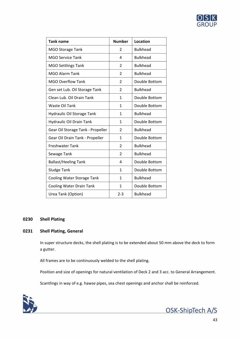
43
Tank name Number Location
MGO Storage Tank 2 Bulkhead
MGO Service Tank 4 Bulkhead
MGO Settlings Tank 2 Bulkhead
MGO Alarm Tank 2 Bulkhead
MGO Overflow Tank 2 Double Bottom
Gen set Lub. Oil Storage Tank 2 Bulkhead
Clean Lub. Oil Drain Tank 1 Double Bottom
Waste Oil Tank 1 Double Bottom
Hydraulic Oil Storage Tank 1 Bulkhead
Hydraulic Oil Drain Tank 1 Double Bottom
Gear Oil Storage Tank ‐ Propeller 2 Bulkhead
Gear Oil Drain Tank ‐ Propeller 1 Double Bottom
Freshwater Tank 2 Bulkhead
Sewage Tank 2 Bulkhead
Ballast/Heeling Tank 4 Double Bottom
Sludge Tank 1 Double Bottom
Cooling Water Storage Tank 1 Bulkhead
Cooling Water Drain Tank 1 Double Bottom
Urea Tank (Option) 2‐3 Bulkhead
0230 Shell Plating
0231 Shell Plating, General
In super structure decks, the shell plating is to be extended about 50 mm above the deck to form
a gutter.
All frames are to be continuously welded to the shell plating.
Position and size of openings for natural ventilation of Deck 2 and 3 acc. to General Arrangement.
Scantlings in way of e.g. hawse pipes, sea chest openings and anchor shall be reinforced.
44
The forward part of the bulbous bows shall be reinforced for impact against stop fender during
berthing at ports at approved speed 0,5nm, and shore fender stiffness as agreed with harbour
designer.
Shell penetration of pipes to be full penetration welded and 100% UT tested acc. to Class. Pipe
ends to be rounded flush with shell plating.
0232 Framing
Hull sides preferably to be transversely stiffened with intermediate ice frames.
0233 Local Reinforcements
Carlings, reinforcements and insert plates to be fitted at/below all heavy or loaded items of
equipment acc. to good shipbuilding practice.
0235 Freeing Ports
Freeing ports on Main Deck shall have an opening area acc. to Load Line Convention. Openings to
be provided with heavy round bar grilles and rubber sheet flaps on the outer side.
Total area of drains and freeing ports shall fulfil Class requirements for draining of water from the
drencher system.
0236 Bilge Keels
The vessel shall be equipped with bilge keels of deep V‐section ‐ 450 mm deep and length of app.
2 x 40 m following the streamlines acc. to model test/CFD.
The bilge keels shall be welded to ground bars of flat bars acc. to Class rules.
The bilge keels shall not extend beyond line of shipside or bottom deadrise line.
0237 Fenders
At car deck height, a steel fender shall be fitted from frame (‐78) to frame (+78). The fenders shall
be 250 mm outside moulded breadth of the vessel and app. 250mm high at outboard side and
with chamfered ends.
The fenders are to be of an entirely closed construction, fabricated in sections and primed
internally prior to welding to the hull. The top plate to be inclined app. 10° from horizontal and
the bottom plate app. 30° from horizontal. The vertical plate to be made of EN Number 1.4404.
45
At life rafts and rescue boat, deflector plates are to be fitted above and below fenders to the
approval of DMA.
All corners to be well rounded.
Final geometry and details to be agreed with designers of ferry berths.
The scantlings of the fenders are to be calculated acc. to below listed standards, but the
thicknesses are not to be less than min. 12 mm:
PIANC Guidelines for the Design of Fender Systems 2002
BS 6349 part 4
Code of practice for design of fender and mooring systems 1994, with approach speed of 400mm/sec for side fenders.
0238 Drain Plugs
Each permanent tank adjacent to the shell shall be provided with a drain plug flush with the shell
plating and at lowest point outside the keel strake.
The drain plugs shall be in stainless steel according to Builder’s standard. The drain screws to be
marked on the shell plating adjacent to each screw by welded letters with tank number and content.
Different type of screw head shall be used for tanks containing oil and tanks containing water. The
plugs are to be opened with a tool from outside (tools supplied by Builder).
Closed structures like skeg, fins and bilge keels shall have sufficient number of drain plugs at top
and bottom for conservation by filling or spraying.
In deckhouse and superstructures, drain plugs shall be provided for draining of condensate to a
deck from the gutters behind linings.
The accommodation to be divided into minor sections with gutter bars, to prevent water running
from section to section.
0239 Spray Rails
At bow and stern, a spray rail shall be fitted appr. 1,0m above design waterline as indicated on
G.A. Final height according to CFD/Model test. Closed triangular steel construction.
46
0240 Bulkheads, Decks & Tanks
0241 Bulkheads – General
Controls for the hoistable decks are to be installed in recesses in bulkheads in way of the side
casings
0242 Decks ‐ General
Longitudinally stiffened and supported by transverse frames and web frames.
Hoistable car decks are to be made as light in weight as possible.
0243 Flush Hatches
See 0308 Engine removal hatches.
0245 Emergency Exits
Emergency exits to be arranged from the Engine Rooms and Azimuth Propeller Rooms as shown
on General Arrangement.
The emergency exits from Azimuth Propeller Rooms aft and fore shall terminate at mooring decks
aft and fore.
The emergency exits from Battery Rooms aft and fore shall terminate at Side Deck level in side
casings.
The emergency exit from Engine Room frame (‐4) to frame (‐6) SB shall connect to stairway at Side
Deck level in side casing.
Insulation of enclosures as per fire safety requirements, and exits from bottom of Engine Room to
be with fire doors.
Emergency exit from sprinkler room to be terminated with a flush hatch on hoistable deck.
0246 Local Reinforcement
Openings for doors and windows to be provided with rounded corners and reinforced by flat bars.
Openings and cut‐outs in bulkheads, web frames and girders shall be placed conveniently for pipes,
ducts and cable trays if appropriate, and shall have rounded corners and be provided with flanges
if found necessary. Position, size and total area of cut‐outs in web plates are subject to Class.
47
0247 Splash Grids
In extension of Passenger Deck fore and aft, splash grids of aluminium are to be installed. The
structures shall protect against sea spray and rain, and must be self‐supporting.
Drainage of water to be arranged acc. to item 0537.
The design and arrangement to be approved by Owner.
0250 Superstructures & Deck Houses
0251 Superstructures
Casings at SB and PS of the Cargo Deck are to be weather tight to the extent practical in order to
contribute to residual stability in damaged condition.
Side casings SB and PS frame (‐66) – (‐78) and frame 66 – 78 should act as weather tight
Forecastle structures.
Exposed corners to have min. R = 50 mm.
The sides of the superstructure in way of car deck shall be provided with openings of sufficient
size to categorize the space as “open vehicle space”. Tentative size shown on General
Arrangement.
On Passenger deck – Deck 4 a superstructure shall accommodate Passenger Lounges, a Shop,
MES‐stations, Sanitary and Catering Areas and stairway/lift casings.
Outboard corners to have R = 600mm, and corners at exterior door recesses to have R = 50mm.
0253 Wheel House
Best possible all‐round visibility to be aimed by minimising size of window posts using rectangular
hollow sections.
Window posts, or mullions, in front of the helmsman’s / conning positions of the centre control
desk shall be avoided.
Pillars in Wheel House to be arranged so that they interfere as little as possible with the functions
of the Wheel House.
Corners may be utilized as drainpipes, in which case the material shall be EN Number 1.4404.
Catwalk around Wheel House shall be built as steel frames with gratings of pull extruded GRP.
48
0254 Decks
Longitudinally stiffened and supported by transverse frames and web frames.
0256 Accommodation Houses
On Sun Deck ‐ Deck 5, a deckhouse shall accommodate Crew areas and technical compartments
acc. to General Arrangement.
Exposed corners to have R = 500 mm.
0258 Funnel
A funnel of steel shall be situated in continuation of engine casings SB and PS.
Corners forward and aft to be as shown on General Arrangement, and corners towards CL to have
R = 100 mm.
Top decks with access are to be provided.
0259‐1 Engine Casing
Engine casing of steel to extent as shown on General arrangement.
Weathertight hinged door to be fitted for access to casings on deck 5.
Inlet and outlet for Engine Room ventilation to be with louvres at inboard and outboard side of
the funnel.
0259‐2 Trunk for Gas Vent Pipe
Gas venting pipe shall be arranged in a steel duct SB side casing app. frame (‐5) on the outside of
the Emergency Exit from LNG Room to top of Acc. House – Deck 6, where it proceed into a mast
to be fitted towards CL.
0260 Foundations
0261 Main Engine Foundations
Foundations for minimizing noise and vibrations to be integrated in double bottom structures.
Seating are to be equipped with access and lightening holes where suitable. Drainage holes
provided as necessary.
49
Engines and generators to be flexibly mounted.
0263 Foundations for Deck Equipment
The foundations for deck machinery to be of open type steel construction welded to deck with
sufficient access for maintenance work (incl. paint maintenance). Foundations to be well stiffened
and dimensioned for maximum load and with drainage where necessary.
For deck machinery, epoxy resin chocks or Solymer to be used for alignment, according to
agreement with the Owner.
0266 Miscellaneous Foundations
All foundations of larger components are to be approved by the subcontractors concerned.
Foundations for machinery are to be provided with coamings for collecting of oil and residues,
and drains are to be arranged. Drainage holes for water and oil to be provided at suitable
positions in all foundations. All drainage of oil and oily water to be drained into Oily Bilge System.
Easy access to foundation bolts and easy maintenance shall be assured (closed foundation or well
accessible open construction). Where not easily accessible for maintenance, closed box type
foundations are to be provided.
0270 Miscellaneous Steel Structures
0271 Chain Lockers
Two (2) self‐stowing Chain Lockers, one (1) aft and one (1) forward, of sufficient size to be
integrated in hull structures on Side Deck adjacent to side shell/bulwark acc. to General
Arrangement.
Steps and handholds to be provided in the side bulkheads for access to bottom.
Surrounding and bottom plate thickness to be three (3) mm above nominal Classification
requirements up to 500 mm above bottom.
Steel grating in bottom, a drainpipe with drain to deck, an access hatch and a bitter end securing
point with release from outside the Chain Lockers to be provided.
50
0272 Hawse‐ & Chain Pipe & Anchor Pockets
Hawse pipes of thick walled pipes to be fitted. The pipes may be inclined for optimal
arrangement. Plates and pipes to be built in stainless steel.
Both ends to be reinforced with wearing bars (Ø30 Solid).
Chain pipes of rolled steel plate to be arranged as close as possible to the centre of each Chain
Locker. Lower end of pipes to have a conical shape and both ends to be reinforced with wearing
bars (Ø30 Solid).
Anchor pockets to be built into shell plating above main deck in SB fore and PS aft, and recesses
to be arranged for anchor dropping well clear of the bow. Builder to ensure that the anchors will
enter the recesses smoothly and correctly without undue scraping.
Anchors to be stowed flush with plating, heavy deflector plates above and below fender to avoid
fouling of anchor when letting go or heaving anchor.
Three (3) washing nozzles connected to fire main for chain washing at each anchor pocket.
0273 Sea Chests
Box cooler/sea inlet chests are to be integrated in the bottom structures acc. to General
Arrangement.
Access to box cooler chests to be provided for diver when afloat and during dry‐docking by hinged
grills of mild steel.
Separate intakes for seawater pumps in other locations shall be provided with sea chests with
hinged grills of mild steel.
0276 Azimuth Thrusters
Rope cutters to be fitted on the hub in the Azimuth Thrusters.
0290 Corrosion, Protection & Painting
0291 General
Prior to commencement of painting, Builder shall present a plan for carrying out all painting work.
This plan shall be presented to Owner and Paint Supplier for approval three (4) weeks prior to
commencement of painting work at the latest.
51
Together with the time schedule for painting work, Builder shall prepare a colour scheme for
Owner’s approval, for the vessel clearly showing the colours to be used on areas all over the
vessel. The same colour scheme shall show marks on car deck for car lanes, escape routes etc.
The Owner shall provide an outline proposal for a colour scheme.
All paintwork shall be carried out under the supervision of a representative of the Paint Supplier
and Owner, and the Paint Supplier shall issue a certificate stating that the paintwork has been
carried out correctly.
The work must be carried out in compliance with the Paint Supplier’s recommendations with
regard to surface preparation, application, temperature, humidity, interval for re‐coating and
ventilation.
Prior to surface preparation and paintwork, all steel work must be completed and approved by
Class. All weldings shall be free of notches, indents and holes in the welding seams, and shall be
approved by Class.
Generally, all temporary pieces to be removed by careful flame cutting/cutting disc/grinding after
completion of the steel work, and the surface to be repaired by welding where necessary and
smoothened by grinding to Owner's approval. Special care to be taken to ensure that the original
plate thickness is not reduced after grinding. All plate edges to be grinded acc. to item 0213.
In some areas, e.g. tanks and machinery spaces, such pieces (e.g. lifting eyes) may remain if
convenient for later maintenance work in accordance with the decision of Owner’s
Representative.
All paint work to be carried out in accordance with the best professional standards and with a
view to easy maintenance. The surface of areas that are not mentioned in the following, are to be
protected to a comparable standard. All edges and transitions between different colours are to be
clean. Equipment that is not to be painted is to be carefully covered before painting of adjacent
areas.
Name and homeport, logo, call signal, draught marks, etc. which are welded on as plate or
welding beads are to be painted in a contrast colour of the Owner’s choice. See Ch. 0370.
All painting of outside surfaces is to be carried out in a closed painting hall. However, a temporary
covering, purpose made and approved by the Owner and the Paint Supplier, may be accepted.
Subject to weather conditions and approval by Paint Suppliers representative, block seams and
final painting may be carried out in open air under suitable and well‐controlled conditions.
52
0292 Preparation of Surfaces
Preparation of surfaces prior to painting shall comply with the requirements of this specification,
the recommendations of the Paint Supplier and the Owner’s instructions.
Primer and paint may not be applied to welding seams of tanks before a pressure test has been
carried out and approved by Class and Owner.
Where the specification states that the dry film thickness is to be equal to or greater than the
specified, this thickness must be present on at least 95% of the area. In no part may the paint
thickness be less than 85% of the specified thickness.
The number of measuring points must either be distributed in a way, or be of a sufficient number,
to establish a statistical probability for assessing whether the paint thickness over the entire area
is acceptable.
An excessive paint thickness shall be avoided.
Steel material must be supplied sandblasted to min. SA 2½ and primed with a shop primer
compatible with the paint system.
Minor blanks, which are not primed, must be sandblasted to SA 2½ and immediately treated with
Zinc Shop Primer (min. 40 µ).
Before commencing painting, the surface must be emulsion cleaned followed by sandblasting or
wet abrasive blasting.
Material containing copper may not be used for sandblasting/brushing of steel parts.
Garnet or similar shall be used for sandblasting of aluminium parts.
All primers must be compatible with the selected paint system.
Marking colours etc. used during building of the vessel may not be of a type, which can have a
negative effect on the paint.
Areas with damage, or corroded areas in places of lesser importance, are to be mechanically wire
brushed to ST3, as agreed with the Paint Supplier.
Areas, where the primer has been damaged due to heat, and welding seams in important areas
e.g. outside on hull and inside tanks, are to be sandblasted to SA2½. If the surrounding primer is
damaged during this process, the edges are to be smoothed with disc sander and repainted as
agreed with the Paint Supplier.
53
All equipment, machines, windows etc., which are not to be painted, but are placed in areas
where paintwork is being carried out, must be effectively protected from blasting and paint spray.
All plate edges, weld seams in wet areas and hard to reach areas, shall be stripe coated with min.
two (2) coats of different colours with brush, to achieve the required thickness before spray
coating is applied.
Galvanized surfaces are to be degreased and coated with a primer before painting.
Corrective work for damaged galvanized parts caused by electric welding etc. shall be carried out
by min. two (2) coats of zinc rich paint before spray coating is applied.
The paint specification for galvanized surfaces is the same as for steel.
0293 Paint Specification
The final Paint Specification is to be agreed with the Paint Supplier.
Specification for 24 mths. docking interval, inner Danish waters, 18 sailing hrs/day and 14‐17 kts.
Stripe coating by brush on plate edges, on weld seams in wet areas and in hard‐to‐reach areas
must be carried out in all areas.
Areas and items not mentioned below shall be treated similar to the adjacent structures.
Hull outside, bottom to waterline Thickness (µm) – dry min.
Preparation: Sa 2½ (ISO 8501‐1) – Medium (S) (ISO 8503‐2) 40‐75 µ
1 x Epoxy Primer 50 µ
1 x Epoxy Glass flake 350 µ 1 x Epoxy tie coat 100 µ
1 x Antifouling 120 µ
Hull outside, bottom to waterline, alternative
Preparation: Sa 2½ (ISO 8501‐1) – Medium (G) (ISO 8503‐2) 60‐100 µ
1 x Epoxy Primer 50 µ
1 x Epoxy Glass flake 350 µ 1 x Silicon tie coat 100 µ
1 x Silicon antifouling 150 µ
Topsides above deep load waterline, superstructures, exposed decks apart from car deck, railings, casings and shipside within car deck and foundations on open deck
54
Preparation: Sa 2½ (ISO 8501‐1) – Medium (G) (ISO 8503‐2) 60‐100 µ
1 x Zinc silicate 75 µ
1 x Epoxy sealer 50 µ
1 x Epoxy primer 150 µ
2 x Polyurethane, each coat 50 µ
Anti‐slint to be applied, including Store Rooms
Vehicle decks
Preparation: Sa 2½ (ISO 8501‐1) – Medium (G) (ISO 8503‐2) 60‐100 µ
1 x Zinc silicate 75 µ
1 x Epoxy sealer 50 µ
1 x Epoxy top coating 150 µ
1 x Epoxy top coating 150 µ
Anti‐slint to be applied
Deck machinery, bollards, rails, masts, etc.
Preparation: Sa 2½ (ISO 8501‐1) – Medium (G) (ISO 8503‐2) 60‐100 µ
1 x Zinc silicate 75 µ
1 x Epoxy sealer 50 µ
1 x Epoxy top coating 100 µ
1 x Epoxy top coating 100 µ
Floors in Engine‐ and Store Rooms
Preparation: St 3 (ISO 8501‐1) on weld seams and damaged areas
1 x Epoxy primer 100 µ
1 x Epoxy primer 100 µ
1 x Epoxy top coating 50 µ
Bulkheads and overhead deck in Engine‐ and Store Rooms
Preparation: St 3 (ISO 8501‐1) on weld seams and damaged areas
1 x Epoxy primer 100 µ
1 x Epoxy primer 100 µ
1 x Epoxy top coating 50 µ
Underside of decks (behind sheet metal lining + visible side of lining)
in car deck space
Preparation: St 3 (ISO 8501‐1) on weld seams and damaged areas
1 x Epoxy primer 125 µ
55
1 x Polyurethane 50 µ
Steel Structures behind linings, incl. substructures for linings
Preparation: St 3 (ISO 8501‐1) on weld seams and damaged areas
1 x Epoxy primer 100 µ
1 x Epoxy primer 100 µ
Ballast Tanks, Heeling Tanks and Chain Lockers
Preparation: Sa 2½ (ISO 8501‐1) – Medium (S) (ISO 8503‐2) 40‐75 µ
1 x Epoxy primer 160 µ
1 x Epoxy primer 160 µ
Void Spaces
Preparation: Sa 2½ (ISO 8501‐1) – Medium (G) (ISO 8503‐2) 60‐100 µ
1 x Epoxy 125 µ
1 x Epoxy 125 µ
Waste Oil / Oily Water Tanks
Preparation: Sa 2½ (ISO 8501‐1) – Coarse (S) (ISO 8503‐2) 75‐100 µ
1 x Epoxy coat 100 µ
1 x Epoxy coat 100 µ
1 x Epoxy coat 100 µ
Cooling Water Drain/Premix Tanks
Preparation: Sa 2½ (ISO 8501‐1) – Coarse (S) (ISO 8503‐2) 75‐100 µ
1 x Epoxy coat 100 µ
1 x Epoxy coat 100 µ
1 x Epoxy coat 100 µ
Compatible with additives used in generator engines
0296 Cathodic Protection
The underwater parts of the hull shall be protected by passive anodes sufficient for 2 years in the
environment conditions.
Anodes to be placed in compliance with the recommendations of supplier, and distributed on
both sides of bilge keels, skeg and fins, inside sea chests, sea strainers and on azimuth propeller
units.
For Sea Chests, see Ch. 0745.
56
0297 Hot Dip Galvanizing
Generally, hot dip galvanizing of app. 60 µ is to be applied for the following items:
Grids and gratings
Outside ladders
Fittings for life buoys, blocks, flag staffs, etc.
Steel shelves in deck stores
Tank vents
Ballast pipes
Corrective work for damaged galvanized parts caused by electric welding etc. shall be carried out
as specified in 0293.
Anodes to be of aluminium or zinc, as per recommendations and suitable for salinity of sea water 1,010 to 1,015.
57
30 Hull Outfit and Equipment
170580.0131.01
Date 16.05.18
Sign MPA/JFH
58
30 Hull Outfit and Equipment
0300 Hull Openings & Closures
In general, shafts, pins, hinges, cylinders, bolts, screws, nuts, washers, fittings etc. are to be of
stainless steel 1.4404. Bushings to be of bronze with easily accessible grease nipples.
At door openings from open decks to Deck Houses and Accommodation, an eyebrow is to be
fitted above the opening for protection against rain/water on the bulkhead.
All doors and hatches must be single hand operated.
0301 Manholes with Covers
All large tanks to have two (2) manhole covers. U‐shaped void spaces to have minimum three (3)
covers, one (1) in each side and one (1) in cross connection duct.
Manholes are to have a clear opening of 600 x 400 mm.
Manholes on tank top in the Engine Room, in insulated tank bulkheads and in FW tanks, are to be
placed on angle bar coamings.
Manholes situated in gangways and in working places are to be fitted with flush covers with a
clear opening of 600 x 400 mm.
Manhole covers on vertical tank bulkheads are to be of hinged type placed on angle bar coamings
with a clear opening of 600 x 400 mm, and are to be positioned at a height of not more than 600
mm from the tank bottom, unless gratings or other footholds are provided. Tanks with vertical
manholes are to be provided with grip handles, steps and ladders inside and outside the tanks to
allow easy access to the tanks according to the location of the tanks and to Buyer’s approval.
All manhole covers are to be fastened by means of studs for stud welding. Nuts and set bolts are
to be of stainless steel.
Gaskets for watertight and oil tight covers must be of rubber/cork rubber suitable for the specific
tank content medium.
Manholes and covers shall be marked with name/no. of the tank in welding beads, and with the
same tank identification as used for drain plugs, in Tank Plan and in Stability Booklet.
0302 Small Hatch Covers
Hinged hatches are to be fitted with locking devices.
59
Hatch sizes are to be defined in detail design, and handrails, grips, rungs and ladders must be
arranged where necessary for access to/from the hatches.
A hatch with clamping dogs, ladders and handholds shall be fitted in the aft bulkhead of the Chain
lockers for access.
Hatches at emergency exits from Azimuth propeller compartments fore and aft shall be situated
on mooring decks. The hatches shall be weathertight with coaming height 600 mm and a clear
opening of 600 x 800 mm.
Handles to be provided both from the inside and from the outside. One (1) clamping handle to be
lockable from the outside and to be releasable from the inside. (Panic lock).
Indication for open/close in Wheel House.
Position, number and size of other escape hatches acc. to General Arrangement and Rules.
0304 Exposed Access Doors
0304‐01 Weathertight Doors on Main Deck
Access from Main Deck to Deck Stores SB/PS fore and aft to be provided with weathertight hinged
steel doors with six (6) clamping dogs.
Height above deck to be 2000 mm, clear width to be 850 mm and height of coaming to be 600
mm.
Indication for open/close in Wheel House.
0304‐02 Sliding Doors on Main Deck/Hoistable Deck
Sliding doors from Main Deck to passenger stairways shall be semi water tight sliding fire doors
with height above deck to be 2000 mm and a clear width of 1200 mm.
Coaming height on deck app. 100 mm.Ramps for wheelchair access must be provided at doors
Leading to elevators.
Sliding doors and coamings from Hoistable Deck to stairways shall be sliding fire doors.Width of
doors to be app. 1000 mm.
Sliding doors are to be self‐closing with pneumatic or electric local operation with push buttons at
either side of the bulkhead. Common air supply from a compressed air system with separate air
receiver on each door as required.
60
All doors to be painted stainless steel.
Fire rating of doors to be A‐60.
Doors from Main Deck to passenger lifts are to be semi‐watertight A‐60 rated fire doors with a
coaming height of 100 mm, and ramps for wheelchair access must be provided at each door.
Door to Garbage Room are to be sliding door with width min. 1100 mm and flush threshold.
Fire rating of door to be A‐60.
Door to room for Drencher Section Valves is to be hinged, opening toward shipside, clear width of
800 mm and with a coaming of 100 mm.
Grating with deck drain are to be installed in full width at the inside of all doors leading to a
stairway.
0304‐03 Exterior Doors on Upper decks
Doors to Crew Accommodation on Sun Deck shall be hinged spray tight doors of GRP with three
(3) clamping dogs, painted and with a window.
Doors to Passenger Accommodation (stairways) shall be hinged spray tight doors of GRP with a
window and three (3) clamping dogs.
Deck drains are to be fitted in the flooring in full width at the inside of all doors leading to open
decks.
0305 Watertight Doors
A total of ten (10) sliding watertight doors are to be provided with six (6) doors in the transverse
bulkheads between the aft and forward Engine Room, and two (2) doors between each Engine
Room/Battery Room and each Battery Room/Azimuth Propeller Room acc. to General
Arrangement. Clear opening app. 1000 x 2000 mm.
The doors must be electro‐hydraulic operated from either side of the bulkheads, and with
indication for open/close and automatic closing in Wheel House. Doorsteps to be flush with
Engine Room flooring with hinged covering ramp plates.
A separate hydraulic hand pump for emergency operation to be provided at each door acc. to
Rules.
Fire rating of doors acc. to Rules.
61
0306 Port Holes & Windows
0306‐01 Windows, General
The vessel is to be equipped with windows of weld‐in type with bead/screws of stainless steel as
shown on General Arrangement. Frames and glass bead to be stainless steel, EN 1.4404.
The windows are to be made of tempered glass with minimum thickness acc. to Class
requirements. Glasses to be protected with plastic foil during the construction period.
Windows to be A‐0 rated where facing external escape routes and muster/embarkation stations
in combination with a sprinkler system covering the windows from inside.
Windows in passenger lounges and crew areas to be with tinted double‐glazing in colours to
Owner’s approval. Sun reduction factor to reduce requirement for A.C. capacity.
Tinting and sun reduction may be obtained by replaceable foil.
Windows/portholes in sanitary spaces to be fitted with opaque foil to Owner’s approval.
U‐value 1.4 W/m²K, sun factor 28% for double‐glazed windows
U‐value 2.0 W/m²K, sun factor 28% for A‐0 double‐glazed windows.
0306‐04 Windows on Passenger Deck
Size in general to be app. 1100 x 1700 mm clear opening with two (2) vertical mullions integrated
in the steel frames, and positions to be arranged to suit tables and compartments.
The number and position of windows acc. to General Arrangement.
0306‐05 Windows on Sun Deck
Size in general to be app. 800 x 650 mm clear opening for Mess Day Room, Office, Crew
Conference, Galley and Relaxing Cabins, and positions to be arranged to suit tables and
compartments.
Reflective foil for privacy to be fitted acc. to agreement with Owner.
The number and position of windows acc. to General Arrangement.
0306‐06 Wheel House Windows
Height of windows to be app. 1500 mm in vertical projection, and width and shape according to
developed shape of Wheel House sides.
62
Window section facing outboard in each bridge wing to be sliding opening type.
The windows are to be provided with non‐tinted double‐glazing.
Demisting of windows by means of the ventilation system and all windows shall have electric
heating in addition to double‐glazing.
All widows to be provided with approved pull‐down blinds for reducing of glare and heat.
Final specification of Wheel House windows shall be approved by DMA.
The number and position of windows acc. to General Arrangement.
0306‐07 Skylight
A skylight is to be fitted on top of Tech. AC Deck fr. 12‐16 acc. to General Arrangement. The
skylight must have a coaming of height 380 mm and a clear opening of 2600 x 3400 mm.
The design to be submitted to Owner for approval.
0306‐08 Glass Entrance Lobby and Shelters on Sundeck
Passenger entrance doors, sun deck fore, shall be protected by a lobby/shelter of glass bulkheads
and roof, and automatic glass sliding doors at either side, as shown on G.A. plan.
At either side of house on sun deck, glass panels to be fitted in line with house side, at recesses in
house side, as shown on G.A. plan. Each recess/shelter shall have two access openings, no doors.
0307 Shell Doors
Shell doors to main passenger stairways (embarkation doors) shall be semi‐watertight and
hydraulic operated.
0307‐1 Embarkation Doors
One (1) weathertight door in SB aft and one (1) weathertight door in PS fore on Passenger Deck
shall be fitted for embarking passengers. The doors shall be double leaf, hull shaped and flush
with the shell plating outside. Clear opening app. 1400 x 2100 mm and opening/closing of doors
to be inward, power operated and clamped. Doors to be fitted with porthole.
Fittings for landing of ramps acc. to agreement with Owner and designers of the ferry berth.
0307‐2 Doors for Bicycles
One (1) non‐tight door in SB aft and one (1) non‐tight door in PS fore on Main Deck shall be fitted
for bicycles. The doors shall have hull shape and must be flush with the shell plating outside. Clear
63
opening app. 1200 x 2000 mm and opening/closing of doors to be inward, manually operated and
clamped.
Fittings for landing of ramps acc. to agreement with Owner and designers of the ferry berth.
0307‐3 Side Doors
For access to Bunker Station when alongside jetty, one (1) non‐tight door are to be fitted
amidships in Main Deck PS acc. to General Arrangement. The door shall have hull shape and must
be flush with the shell plating outside. Opening/closing of the door is to be inward, manually
operated and clamped.
The Bunker Station shall include connections for bunkering of MGO, Lub. Oil and FW, and
connections for discharge of sludge and sewage. Pipes for FW and Sewage to be separated min 2
m.
For access to LNG Bunker Station, one (1) semi‐watertight door are to be fitted amidships in Main
Deck PS acc. to General Arrangement. The door shall have hull shape and must be flush with the
shell plating outside. Opening/closing of the door is to be inward.
0308 Engine Removal Hatches
One (1) flush weathertight hatch, app. 2000 x 2000 mm, integrated in the Main Deck app. frame
21‐24 to be installed above the Workshop. Position and size of the hatch acc. to General
Arrangement. The hatch is to be hinged, fitted with locking devices and hydraulically
opening/closing and with clamping.
One (1) flush weathertight hatch, app. 1100 x 1400 mm, integrated in the Main Deck app. frame
26‐28 to be installed above the Workshop. Position and size of the hatch acc. to General
Arrangement. The hatch is to be hinged, fitted with locking devices and hydraulically
opening/closing and with clamping. Manual lock of system, with indication to wheelhouse.
Two (2) flush weathertight hatches integrated in the Main Deck to be installed above Engine
Room aft and fore. Position acc. to General Arrangement. Size of the hatches to be according to
supplier’s recommendation, and it should be able to lift one (1) complete Main Engine with
generator attached up/down through the free area of the hatches.
Two (2) flush weathertight hatches integrated in the Main deck to be installed above Azimuth
Propeller Room aft and fore. Position acc. to General Arrangement. Size of the hatches to be
according to supplier’s recommendation, and it should be able to lift one (1) complete Thruster
up/down through the free area of the hatches.
64
The hatches are to be arranged to avoid intersecting the main web frames/girders of the deck
structures, and pipes and cables are to be kept clear from the hatch openings. The areas on the
Tank Top below the hatch openings must correspondingly be kept free of machinery and
equipment.
Cladding of fire insulation in Engine Rooms to be fitted in detachable marked sections around the
hatches.
Hatch covers to be supported by steel chocks to avoid overloading of the rubber gaskets.
Covers to be screwed down with stainless steel bolts.
To gain access to the lower compartments, threaded lifting sockets are to be fitted in top of each
hatch cover for lifting the covers by chain hoist or crane.
Scantlings of all hatch covers shall be corresponding to full design load of the surrounding deck
structures.
Clamping/opening devices etc. must not reduce the clear opening of the hatches.
Sockets for protective rails, screens or guards as appropriate and necessary are to be fitted in the
deck to safeguard the crew, when operating the deck openings.
0310 Access & Protection
All items of machinery or equipment must be removable by hatches or bolted panels as
appropriate.
0312 Embarkation Ladders
For emergency embarkation to Life Rafts and Fast Rescue Boat, one (1) pilot rope ladder is to be
provided at each side of Sun Deck acc. to General Arrangement.
The ladder and the arrangement is to be approved by DMA.
0313 Stairs & Ladders
All passenger stairways must have an inclination of preferably 36°, max 45°, as shown on General
Arrangement, and must be longitudinally orientated. Stairways on decks and in Engine Room to
be made with side stringers of plate or profiles with galvanised perforated steel steps. Inside
casings, steps are to be integrated in the steel structures.
65
Stairs on open decks to be bolted to the deck.
Engine room stairways to be provided with steel screens on lower sides.
Enclosed stairways in accommodation are to be of steel and to form part of the fireproof
subdivision between deckhouse tiers. Steps are to be covered with material corresponding to the
surrounding floor coverings. Edges to be provided with non‐slip wearing strips.
Ladders to be provided for access to e.g. top of Wheel House, Catwalk, Wheelhouse Deck, inside
casing and outside of funnels etc.
Vertical ladders to be with square steel bar steps placed on the diagonal, min. 400 mm wide.
Safety arrangement for ladders on masts etc. according to DMA Rules. Details according to DVS,
NS or similar.
Manhole openings in bulkheads in all double bottom tanks and deep tanks are to be provided
with grip handles, steps and ladders inside and outside the tanks as appropriate for access.
Steps are to be provided below all weathertight doors with coaming height above 300 mm.
0314 Railings
Rails around Sun Deck to be 1100 mm high.
Top of rail to be a stainless steel pipe with a flatbar below for terminating vertical flatbar
banisters.
Doors in rails as per usual practice.
Storm hand rails to be fitted on exterior bulkheads of all deckhouses surrounded by free decks
incl. casing for Funnel and trunks for lifts.
Hand rails on both sides in interior stairways and on external stairs. Handrails shall as a rule be
fitted without free ends in stair casings, in corridors and on internal and external stairs, to prevent
“snag on” accidents.
Rails around Wheel House Deck and Monkey Island shall be of non‐passenger “Load line” type as
shown on General Arrangement.
The rails may be of aluminium alloy for weight reduction, or hot dip galvanized steel, consisting of
horizontal pipes and stanchions of plate with bent flanges. Connection to steel by means of
compound metal strips (in case of aluminium rails). Height of rail to be 1100 mm. GRP‐pultruded
rail sections may be considered as alternative.
66
Protective rails, screens or guards as appropriate and necessary, to be fitted to safeguard crew
when operating deck machinery, deck openings or other hazards.
Handrails in accommodation are to be according to the Architect Specification.
0316 Tarpaulins
Tarpaulins to be provided for Reflector Compass, Fast Rescue Boat and Embarkation Ladders.
0317 Passenger Lifts
One Passenger Lift for electric or hydraulic operation with machinery integrated in the trunk to
be provided on Main Deck SB aft and correspondingly in PS fore acc. to General Arrangement.
Stopping levels: Main Deck – level 2
Hoistable Deck ‐ level 3
Passenger Deck ‐ level 4
Capacity: Duty load 1800 kg
Number of passengers 24
Speed min. 0.6 m/sec
Lift cabin size: 1600 x 2300 x 2100 mm (W x D x H)
The lift cabins, doors and arrangement shall enable transport of
a person on a wheeled stretcher and accompanying personnel.
Cabin door: 1000 x 2050 mm telescopic, opening from centre to either side.
Lift doors to face stairway landings. On car deck and passenger
deck level, the lift cabins to have one additional door of similar
specification to A‐60 standard,
The door to sick bay shall be separately lockable to avoid
passengers entering the sick room by mistake.
Landing doors: 1000 x 2050 mm, self‐closing/opening.
Landing doors from lift to open car deck shall be splash tight in
addition to the required fire rating, hinged steel door, for crew
use only Coaming shall be provided with ramp, suitable for use
with wheeled stretcher or provisions trolleys.
Hand rails to be fitted at three (3) sides on cabin and at control panel.
67
Finish of exterior of lift cabin and doors, etc. to be brushed stainless steel.
Mirrors to be fitted in lift cabins.
Controls, safety equipment, emergency lighting, communication and emergency exits as per
relevant clauses of these specifications and as required by Statutory/Class regulations Including
accessibility by disabled persons.
Platform Lift on Passenger Deck frame 8‐10 to serve as lift for a wheelchair and one helper. Lift to
be of spindle type with 50 mm lift pin, speed of 0,15 m/sec and cabin size app. 1450 x 1400 mm.
0320 Rigging & Deck Fittings
0321 Main Deck
Marking of lanes and walkways on deck with paint of different colours for private car lanes and
truck lanes to be approved by DMA and Owner.
Lashing fittings to be fitted in Main Deck according to Cargo Securing Manual. App. 80 pcs. flush
cloverleaf type for "elephant foot" for trailer lashings with tight fitting plastic cover to be fitted.
Bicycle holders shall be provided at SB and PS amidships acc. to General Arrangement ‐ app. 50
pcs. in either side.
All details of arrangement and outfitting on Main Deck to be approved by Owner.
0322 Masts for signal lights, flags & radars
One (1) unstayed pipe mast to be fitted in centre on top of Wheel House. The mast to be provided
with cross‐yards, fittings and consoles for signal lights, antennas and electronic equipment.
Halyards and cleats for dressing flags to be arranged and fitted where necessary.
Two (2) posts for radar scanners on Wheel House top to be fitted diagonally symmetric for best
radar view.
Two (2) wire stayed masts of aluminium to be fitted at fore‐ and aft end of Sun Deck as shown on
General Arrangement with double sets of upper‐ and lower masthead lights and anchor lights.
Means to be provided for lowering and raising of the mast without aid of a crane enabling lights
to be serviced from the deck, and when requiring deck space for Helicopter pick‐up.
68
Screens for double sets of side lanterns to be fitted at rails at Sun Deck. Position and sizes
according international regulations and to DMA approval. Access from deck for servicing of
lanterns.
Ladders for access to all fixed masts and posts to be fitted out with equipment for personal safety
according to DMA requirements.
0330 Anchor & Mooring Arrangements
All anchoring and mooring equipment shall be in accordance with the Regulations of the
Classification Society.
The hydraulic system shall be connected to the hydraulic system for the ramps and the hoistable
deck – see Ch. 1018.
0331 Anchors & Anchor Chains
Two (2) stockless HHP anchors, 2 x 3300 kg, to be stowed in anchor pockets flush with shell
plating.
Size based on preliminary calculation of equipment no. between 1060 and 1139, and with
reduction for specified operating area and High Holding Power Anchors.
Final equipment in accordance with equipment number calculation be carried out by Builder.
Anchors to be treated with a suitable bituminous paint.
Anchor chains to be of a length of 495 m with diameter of Ø46 and material quality grade K3
divided between the two (2) chain lockers.
Anchor chains to be marked for each shackle as per common marine practice.
Chains to be treated with a suitable bituminous paint.
Anchor arrangement, incl. operating panel arrangement, according to Owners approval.
0332 Anchor Winches & Chain Stoppers
Two (2) hydraulic anchor winches to be provided at mooring decks SB fore and PS aft.
The winches to be of compact design with motors, or orbit gears, within the brake drums.
69
Manual brakes to be provided.
The winches shall be capable of lowering by hydraulic power and be able to be free running
without pressure on the hydraulic system.
Chain stoppers combined with rollers to be provided. Chain stoppers shall be operable by hand
with an anchor hanging in the chain.
Anchor securing by wire and screw spindle to be provided.
The winches shall be controlled locally including start/stop of the hydraulic system.
0334 Mooring Winches
Four (4) hydraulic mooring winches to be provided, one (1) on each mooring deck SB/PS fore and
aft.
The winches to be of a compact design with motors, or orbit gears, within the brake drums.
The winches shall each have two (2) drums, which can be operated separately by hydraulic
clatches and brakes.
Warping heads to be provided on main shaft. .
The winches shall have a control locally, as well as on the navigation bridge.
0335 Bollards, Hawseholes and Fairleads
Two (2) double bollards to be fitted on each of the four (4) mooring decks.
The bollards shall be placed to guide mooring ropes from winch drums and warping heads to the
fairleads most aft and most forward. acc. to General Arrangement.
Two (2) Panama type hawseholes to be fitted in each bulwark at the four (4) mooring decks acc.
to General Arrangement.
One (1) fairlead of 2‐roller type and one (1) fairlead of 3‐roller type to be fitted in each bulwark at
the four (4) mooring decks acc. to General Arrangement.
Additional fairlead rollers may be required.
0336 Rope Reels
Four (4) Rope reels of rolled heavy gauge aluminium pipe to be provided – one (1) on each
mooring deck.
70
0337 Mooring Lines
Four (4) mooring lines, each 200m of breaking strength 250 kN, with a soft eye in each end.
Four (4) mooring lines, each 200m of same specification as above to be supplied and stored in the
rope baskets.
Two (2) heaving lines to be supplied.
0339 Automatic Mooring Arrangement / Equipment
An automatic mooring system is to be used for mooring with PS to the quay, aft end in Vesterø
and fore end in Frederikshavn. Final make and type to be determined by Owner.
Position of attachment to be in SB/PS frame (+/‐) 36 and (+/‐) 44 between Main Deck and
Passenger Deck. Design loads for reinforcement of shell structures are to be agreed with
designers of the ferry berth/mooring system.
The shell plating in affected areas are to be smooth and without any obstacles.
The deck areas of mooring system shall be provided with heat tracing.
0350 Life Saving Equipment
The vessel is to be equipped with lifesaving appliances in accordance with DMA requirements for
vessels in Domestic Passenger Service ‐ Sea Area "B" for 760 persons.
0353 Life Rafts
0353‐1 Marine Evacuation System (MES)
Main System
The main units shall be installed in separate rooms on Passenger Deck amidships; one (1) in SB
and one (1) in PS, just forward of the Main Vertical Zone Bulkhead with access from both zones,
and the system comprises 1 x 150 life raft combined with a chute in each side.
The rooms shall be A‐60 insulated towards accommodation areas.
Additional MES Life Rafts
71
Two (2) x 150 life rafts + four (4) x 150 life rafts of similar specification as above and stowed
independently and distributed evenly in SB/PS on tilting cradles on Sun Deck acc. to General
Arrangement.
Float free devices, tether lines, split tubes and connection to manuals and remote release systems
as required.
Number and capacity may have to be adjusted according to actual raft sizes of manufacturer.
Make and type according to agreement with the Owner
Instructions and drawings:
Four (4) sets Installation instructions and drawings.
Four (4) pcs. Instruction posters in coloured hard plastic for crewmembers
Four (4) pcs. Instruction manuals (in English & national language) for crewmembers
One (1) instruction film
One (1) instruction movie for passenger safety instructions.
0353‐2 Additional Life rafts/slides for ambulance personnel and patients
At each of the two (2) embarkation doors on Main Deck, one (1) separate inflatable life raft and
mini‐slide shall be provided for persons transported in ambulance with two (2) accompanying
personnel.
Two (2) x self‐righting canopied inflatable life rafts, Emergency Pack B, throw‐overboard
launching.
Two (2) x Mini Slides to be attached at boarding door.
0354 Fast Rescue Boat/Means of rescue
One (1) Fast Rescue Boat (FRB) to be SOLAS / DMA approved.
Rigid fibreglass hull with fibreglass inner liner/floor and foam filled collar/fender.
Inboard diesel engine/water jet with sufficient engine power for towing of life rafts.
Central steering console.
Electric start of engine and automatic battery charging unit.
Watertight searchlight connected to boat electric system.
Rigid single point hoisting system with release hook.
Cradle for stowage and launching with quick release of boat seizings
Equipment in accordance with SOLAS.
72
Tarpaulin for covering of FRB to be supplied. The tarpaulin to be readily removable.
Painter for FRB shall be fitted at shipside in split tube in a height to suit the launched position of
the boat.
Means of Rescue: one MOR inflatable raft/basket to be arranged. MOR to be lowered/hoisted by
FRB davit after launching of FRB (See 0357).
0355 Miscellaneous Safety Equipment
600 pcs. life jackets for adults, including persons over 140 kg, to be stowed in each of the
passenger lounges (For the event of fire in one (1) Muster Area.
150 pcs. life jackets to be stowed in Life Jacket Stores on Sun Deck.
120 pcs. life jackets for children to be stowed with half in each of the passenger lounges.
20 pcs. life jackets for infants to be stowed with half in each of the passenger lounges.
Make/type of life jackets with compact stowed measurements with whistle and lights to Owner’s
approval.
Four (4) pcs. immersion suits for FRB crew, assorted sizes.
Eight (8) pcs. anti‐exposure suits for remaining crew, assorted sizes.
Eight (8) pcs. inflatable life jackets for crew.
Six (6) pcs. life buoys with light and line.
Two (2) pcs. life buoys with light and smoke signal mounted in launching chute at Wheel House.
Remote release from Wheel House.
One (1) pc. line throwing apparatus.
One (1) pc. hoistable stretcher.
All equipment to be acc. to DMA requirements.
All type and make according to agreement with the Owner.
0357 Fast Rescue Boat Davit
One Fast Rescue Boat davit of A‐frame pivot type with hydraulic and manual operation. Launching
of boat by gravity or stored power.
Hoisting speed, shock absorber and wire tensioning system as may be required by DMA for the
sea area in question.
73
Electric and hydraulic system shall be to highest standards regarding durability and low
maintenance. Hydraulic pipes and fittings shall be stainless steel.
The Davit shall be capable of handling the MOR raft, including safe landing area for rescued
persons on sun deck level.
0358 Escape Calculations
Escape calculations in accordance with IMO‐guidelines MSC.1/Circ.1533 to be carried out by
Builder and approved by DMA at an early stage of the design.
0360 Non Electric Navigational Equipment
In addition to the nautical instruments listed in electronics (Chapter 8), additional nautical
equipment shall be delivered as required by relevant Authorities, and as a minimum consisting of
the following listed in 0361 – 0369.
0361 Magnetic Compass
One (1) pc. Magnetic reflector compass for installation in binnacle on top of Wheel House with
cover and electric lighting, and with elelctronic remote reading at conning positions,
One (1) pc. pelorus to be supplied and stowed in chart table/locker.
Two (2) pcs. mounting brackets for pelorus to be fitted in Wheel House, one (1) at either side to
enable bearings over an arc of 360 degrees to be taken.
0362 Clocks
See 0876 Electrical clock system
0363 Flags
One (1) complete sets of signal flags with sufficient no’s of dressing flags.
One (1) national Danish flag, size to Owner’s approval.
One (1) name flag, size and design to Owner’s approval.
0364 Signal Equipment, Distress Signals
One (1) Aldis signalling lamp
Three (3) black day signals spheres, two (2) cones.
Pyrotechnical distress signals to DMA requirements.
74
0366 Fog Bell
One (1) pcs. 12" bell to be stowed in wheelhouse.
One (1) Gong to be stowed in Wheel House.
Fittings for bell and gong to be located at funnel casing for‐ and aft, easy attachment of bell/gong
to be provided.
0367 Megaphone
One (1) hand held electric megaphone to be stowed in Wheel House.
0369 Other Instruments, Inclinometer
Two (2) pcs. thermometers, electronic for measuring of inside/outside temperatures.
One (1) pc. marine aneroid barometer 6" of brass in Wheel House.
Four (4) pcs. inclinometers – two (2) pcs. in Wheel House and (2) pcs. in Engine Rooms).
Four (4) pcs. binoculars 7 x 50 marine type mounted in teak boxes in Wheel House.
One (1) pc. parallel ruler.
One (1) pc. divider in brass.
0370 Marks & Identification
0371 Marks for In Water Survey notation
Tanks and frames shall be marked in acc. with Class notation for in‐water survey with welding
bead on the shell plating indicating frame lines, tank boundaries and names of tank. Tank
identification as used for drain plugs, in Tank Plan and in Stability Booklet.
0372 Load Line, Draft Marks & Waterline Marks
Freeboard marks of steel plate to be welded onto hull amidships after approval of freeboard
calculations and acc. to Class requirements.
Draught marks are to be fitted at either side of bow and stern at app. frame 78 in steel plate
letters welded onto the shell plating. Arabic figures for every 0.2 m with the letters being 0.1 m
high (the projected height).
Boot‐top line and other pain lines on the hull are to be marked with welding beads.
0373 Letters of Registration, IMO‐No. and Tonnage
Letters of registration and gross tonnage to be welded onto aft engine room bulkhead.
IMO‐No. to be marked at suitable locations for fulfilment of Class requirements.
75
Letters to be cut of steel plate and welded onto plating.
0374 Name, Port of Registry
The vessel's name and port of registry shall be welded on bulwarks fore and aft.
Letters to be cut of steel plate and welded onto the plating.
0375 Owners Marks, Bow Mark
Owners Bow Mark of steel plate to be welded to bow/stern visor in CL. Size and design of letters
and marks to be supplied by Owner.
Owner’s name and logo to be cut in stainless steel plate and fitted detachable on distance pieces
on the outside of the Funnel. Size and design of letters and logo to be supplied by Owner.
0376 Thruster Marks
Symbols for azimuth thrusters to be marked on shell plating fore‐ and aft in welded steel plate.
0390 Miscellaneous Hull Equipment
0393 Hull Fittings for Electronic Equipment
Transmitters in tanks with approved sea valves shall be fitted at suitable and accessible locations
to avoid interference from propellers etc.
See Ch. 0985 for Draught sensors.
Precautions shall be taken to prevent flooding of engine room or other compartments in case of
loss or damage of the probe.
Precautions shall be taken to prevent flooding of engine room or other compartments in case of loss or damage of the probe.
76
40 Accommodation
170580.0131.01
Date 12.04.18
77
40 Accommodation
0400 Accommodation, General
0401 Accommodation, General Requirements
Principles for accommodation are indicated on the General Arrangement.
The layout shall allow for closing down sections of the public spaces during low season to
minimize cleaning and maintenance.
Six (6) stanchion sprung loaded queue control halt barrier, each with a length of five (5) meter.
The interior shall reflect a modern North European ferry style, typical for the envisaged route
between Vesterø and Frederikshavn. For reference to quality of materials and workmanship, the
ferry M/F TBD shall be used.
Quality of finish for mounting of floor, lining and ceiling, according to Owners final approval.
Choice of material and methods shall aim at a silent environment. Emission of structural noise,
and rattling or squeaking sounds, shall be avoided. Noise in public areas from passengers, play
area and catering/serving activity shall be damped by perforated ceilings, baffles or other
appropriate measures.
Maximum noise level in passenger areas shall be below 60 dB(A)
All DMA legislation regarding living quarters, noise level, occupational health, and transport of
passengers, including disabled persons, is to be observed.
All materials and furniture to be first class north European quality, chosen with regard to use in
marine environment, ease of cleaning and maintenance and durability. All material to be selected
from well‐known companies with marine experience, and certificate of compliance with marine
standard is to be provided.
Lightweight materials and solutions are to be used throughout.
Materials liable to cause allergic reactions are to be avoided.
All fittings to be of brushed stainless steel.
78
The builders shall compile a final sample book showing all visible agreed material, colours,
designs, fittings and fixtures. The final sample book shall cover all accommodation areas, public
stairways, outside public deck area, sanitary spaces and Wheel House.
The sample book shall be based on suggestions and sketches prepared by the Owner’s interior
architect – see 0402.
0402 Design / Artist's Impressions
A Colour Coordination Book, is to be approved by the Owner, the book ensure that the colours,
the materials, the textures, furniture and room structure are coordinated throughout the vessel.
The Colour / Material Coordination Book is to describe and guide in selection for Public Spaces
and Crew Accommodation as follows:
Flooring
Walls and doors
Ceilings
Decorative partitions
Special features
Lightning arrangements
Curtains, blinds and sunshades
Window boxes
Textiles
Loose and Fixed Furniture
See 0496 for lump sums art decoration.
0406 Structural Fire Protection
A Structural Fire Protection plan is to be prepared by the Yard immediately after start up, to be
approved by authorities and Owner. Preferably, lightweight insulation material of ceramic type is
to be used.
0407 Sample Boards /Mock‐ups
Mock‐ups of the areas mentioned below are to be prepared by the Builder for the Owner’s
approval prior to production:
Section of Window area in public spaces complete with surrounding lining, lighting, curtains, blinds, fittings etc. – incl. supporting pillar.
Samples of material, fittings and transition of floor/bulkhead to be presented
79
Samples of galley materials and fittings, including all assembly details of floor, lining and ceiling.
Samples of material and fittings of outlet area, including all assembly details of floor, lining, ceiling and furniture.
Section of Freestanding sofa incl. room dividers. (if not included in public space area mock‐up)
Bridge consoles regarding the ergonomically functionality (man ‐ machine
interface)
Inspection Hatch and Fire Hose Box, sample
Handrails, sample
Final selection of areas to be submitted to Owner for approval before manufacturing.
0408 Signage in Accommodation
Signage plans, orientations displays, and commercial signage to be prepared by the Yard in
cooperation with Owner’s architect.
Required fire‐ and life safety signage to be coordinated with other signage and displays.
Passenger Information Signage
Comprises signs for access doors from and to car decks, deck information signs, directional signs
in staircases and public spaces, general arrangement signs, and signs for all passenger related
spaces and facilities.
All signs to be well lit by direct or internal lights.
Miscellaneous Signage
All signs and instructions necessary for easy identification of equipment, installations and the safe
and efficient operation of the ship are to be installed in accordance with the rules and regulations.
All signage plans are subject of Owner’s approval.
Handrails, lifts, etc. to be provided with tactile information in Braille, arrows etc. as required by
rules for accessibility by disabled persons.
In connection with color choices in the accommodation, focus on contrast colors to help visually
impaired is important.
80
0410 Crew Accommodation
0411 Crew Accommodation Arrangement / Plans
Crew Accommodation is to be arranged in principles as shown on General Arrangement, and in
accordance with requirements of National Regulations.
Large scale (1:50) plans and elevation of final arrangement of all Crew Accommodation areas ‐
incl. furniture, fittings, lights ceiling arrangement etc. ‐ are to be presented and approved by the
Owner.
0412 Crew Relax Cabins
At deck 5 –six (6) crew relaxation cabins are to be arranged.
Crew Relax Cabins Material selection
Flooring Vinyl/Rubber
Walls 25/50 mm Soft‐core panels with non‐PVC
Foil and/or Hard core panels with laminate.
Ceiling Modular steel panels with baked enamel
coating
Each of the cabins to be furnished as follows:
One (1) – Bed (Mattress 2050x900) with double lockable drawers
One (1) – Relaxing chair
One (1) – Small folding table (office table)
One (1) – Wardrobe with coat hanger and shelves (2000x1300x600) with four (4) lockable doors
One (1) – Wall mounted Mirror (1400x600)
Coat hangers
Bed lamp, reading lamp and ceiling lamp
0413 Mess Room/Pantry
At deck 5 – a Crew Mess/Dayroom room is to be arranged.
Crew Mess Room Material selection
Flooring Vinyl/Rubber
Walls 25/50 mm Soft‐core panels with non‐PVC
Foil and/or Hard core panels with laminate.
Ceiling Modular steel panels with baked enamel
coating
81
The Crew Mess to be furnished as follows:
Two (2) – Dining tables (2000x800)
Fourteen (14) – Chairs, with armrests
One (1) corner sofa according to GA
Two (2) coffee tables
One (1) – Sideboard, according to GA, with cabinets below – 2 cabinets to be lockable.
One (1) – Table top of stainless steel with integrated sink and faucet, above:
o One (1) – Dishwashing Machine (800x600x600)
o Base Mounted Cabinets with drawers
o Wall mounted Cabinets with double doors (900x600x300) above the Pantry table top – 2 cabinets to be lockable.
One (1) – Coffee Machine
One (1) – Combined small micro wave / oven (Power to be limited by regulations for space designated as “pantry”)
One (1) – Combined refrigerator and Freezer – build in type (2100x600x600)
One (1) – Wall mounted Newspaper holder
One (1) – Wall mounted whiteboard (1200x900) with markers
One (1) – Wall mounted flat screen TV (30”)
Coat hangers
0414 Stairways and Corridors
Crew stairways and corridors to be arranged as shown on General Arrangement.
Crew Stairways and Corridors Material selection
Flooring Rubber Tiles – Steps for stairs with integrated
anti‐skid step front
Walls 25/50 mm Soft‐core panels with non‐PVC Foil
and/or Hard core panels with laminate.
Ceiling Modular steel panels with baked enamel
coating.
Stair ‐ Joiner Work Fittings and coverings iwo stairs flights to be
of brushed stainless steel sheet plate.
0415 Toilets, Bathrooms and Change Rooms
Crew Toilets:
82
Two (2) crew toilets are to be arranged on deck 5, as shown on General Arrangement and one
Bridge toilet on the tech deck 6 (level of landing and toilet is recessed 17250 abv. BL) ‐ Bridge
toilet also to lit by “red light”
Crew Toilets Material selection
Flooring Anti‐skid Resin/epoxy
Walls 25/50 mm Soft core panels with non‐PVC Foil
Ceiling Modular steel panels with baked enamel
coating.
Each toilet to be furnished as follows:
One (1) – white china toilet bowl
One (1) – white china wash basin with faucet
One (1) – mirror (800x800)
One (1) – waste bin with foot operated lid
One (1) ‐ Large toilet paper dispenser
One (1) Toilet brush and holder
Grab handle
Coat and towel hooks
Dual Soap dispenser
Paper towel dispenser
Door with red/green indicator lock
Change Rooms – Toilets/Shower
Two (2) crew change rooms with toilets and showers are to be arranged on deck 5, as shown on
General Arrangement,
Crew Change Rooms/Toilets Material selection
Flooring Anti‐skid Resin/epoxy
Walls 25/50 mm Soft core panels with non‐PVC Foil
and
Ceiling Modular steel panels with baked enamel
coating.
Each Change Room section to be furnished as follows:
Modular Metal Cabinets (400x500x2100) in numbers as shown on General Arrangement ‐ with latch for padlock (Not part of locking system) and with benches in front (integrated)
Two (2) – mirror (1200x800)
83
Two (2) – Power outlet (230 V) adjacent to mirrors
One (1) – waste bin with foot operated lid
Coat and towel hooks
Two (2) Shower rooms, each to include:
o One (1) – Shower unit with thermostat mixer, sliding track and hose head
o One (1) – Shower curtain
o Dual Soap dispenser
o Grab Handle
o Coat and towel hooks
o One (1) bench
Two (2) Toilets to include:
o One (1) – white china toilet bowl
o One (1) – white china wash basin with faucet
o One (1) – Mirror (800x800)
o One (1) – Power outlet (230 V) adjacent to mirror
o One (1) – waste bin with foot operated lid
o One (1) Toilet brush and holder
o Paper towel dispenser
o Door with red/green indicator
Engine Room Changing facilities
Adjacent to engine control room and crew stairway, a changing room to be arranged as shown on G.A. comprising, lockers, toilet, shower with door, wash basins, all to same standards as crew changing rooms above.
Heavy duty washing machine and tumble dryer for work clothes.
0416 Stowage for Life Jackets
Life jackets shall be stowed in sofas, benches and lockers in passenger lounges on deck 4.
Stowage to be arranged for life jackets in excess of rule requirements to achieve doubling of
jackets stored in opposite MVZ saloon.
Access and shelving to be arranged as necessary.
0417 Offices / Meeting Rooms
Office and Conference room to be arranged on deck 5 with connecting door
Crew Office / Conference Room Material selection
Flooring Vinyl/Rubber
84
Walls 25/50 mm Soft core panels with non‐PVC
Foil
Ceiling Modular steel panels with baked enamel
coating
The office to be furnished as follows:
Two (2) – Working table (1500x600) with two (2) working stations. Each working station with a four (4) drawer unit. Outlet for PC power and LAN above table.
Two (2) – wall mounted working lamps
Two (2) – Office working Chairs
Open shelved with storm rails and Cabinets with shelves (2100x600x600) according to GA – two (2) to be lockable
One (1) – White Board (1200x900) with markers
Coat hangers
The conference room to be furnished as follows:
One (1) ‐ Meeting table (2600x900)
Ten (10) ‐ Meeting Chairs
The conference table to be with integrated outlet for PC power and LAN.
One (1) – White Board (1200x900) with markers
Coat hangers
TV (65”)
0418 Crew Gymnasium
Crew Gymnasium to be placed on deck 4
Crew Gymnasium Material selection
Flooring Vinyl/Rubber
Walls 25/50 mm Soft core panels with non‐PVC Foil
Ceiling Modular steel panels with baked enamel
coating
The gymnasium to be equipped with as minimum:
One (1) – large mirror (1800x1200)
One (1) ‐ Exercise bike
One (1) ‐ Rower
One (1) – Elliptical cross trainer
One (1) – Bluetooth loudspeaker
One (1) – TV (50”)
85
One (1) ‐ Treadmills
One (1) – one full height cabinet with movable shelves
Wall bars (full hight)
0420 Service Spaces
0421 Service Spaces Arrangement / Plans
Service spaces are to be arranged in principles as shown on General Arrangement, and in
accordance with requirements of National Regulations and classification society.
Large scale (1:50) plans and elevation of final arrangement of all Service areas ‐ incl. furniture,
fittings, lights ceiling arrangement etc. ‐ are to be presented and approved by the Owner.
0422 Wheel House
Wheel House Material selection
Flooring Anti‐static, non‐skid Rubber tiles
Walls 25/50 mm Soft core panels with PVC Foil and/or
Hard core panels with laminate.
Ceiling Modular steel panels with baked enamel
coating – non reflecting
Bridge construction, lay‐out, equipment, instruments and installation shall be arranged in full
compliance with all applicable rules and regulations in relation to DMA, the Classification Society
and IMO. Further ISO guideline for bridge layout shall be adhered to.
Arrangement and installation shall further be based on ISO 8468 and the "Guidelines on
ergonomics criteria for bridge equipment and lay‐out (MSC/Circ. 982‐20. Dec. 2000 as amended)"
with possible deviations subject to the Owner’s approval.
The layout/design shall incorporate ergonomic aspects and be approved by Owner and DMA for
Work Environment.
All equipment shall be installed in purpose‐designed consoles for bridge and/or ceiling mounting
to the Owner’s approval and shall be installed in accordance with the configuration and service of
the vessel as double‐ended ferry.
The final bridge lay‐out and arrangement of consoles and instruments shall be carried out to the
Owner’s approval. Hence the Builder shall prepare a mock‐up in scale 1:1 of the Wheel House,
86
including windows, ceiling‐mounted equipment, panels, chairs and consoles with instrumentation
etc.
Manoeuvring consoles shall be arranged in principle as indicated on the GA plan and shall be
supplemented with workstation consoles and lockers to Owner’s approval and in adherence with
above regulations and as required by DMA.
The Wheel House shall be arranged in the following main sections:
Manoeuvring console(s)
Chart Table Section ‐ allowing for view in both directions
Safety Central
Machinery Monitoring Work Station
Pantry and Sitting Area
Manoeuvring Consoles
Two (2) identical U‐Type manoeuvring consoles – Fwd and Aft. Each console fitted for with two (2)
pilot chair on recessed tracks – sliding abt. 1.5 m.
Each of the manoeuvring consoles shall be equipped with the required instruments for safe
navigation – in general with main controls and displays as follows:
ECDIS (and ECDIS backup)
Communication
Chart Radar
Heading & Speed
Engine/Generator
Manoeuvring
Conning
Radar
Final position of controls and displays to be decided in conjunction with presentation of mock‐up
(0407).
Chart Table Section
A chart table section to be arranged comprising the following:
Chart table with drawers for full size charts. Top of chart table to be covered by hard lexan type plate – allowing for charts below.
Working table section
Stowage for chart devices, conning display repeater
87
Bookshelf above, towards desk area
Safety Central Section
A Safety Central Section it to be arranged at central casing, adjacent to machinery monitoring
section. The information collected, displayed and/or controlled at the Safety Central Section may
be – but is not limited to:
Fire alarms, detection and extinguishing control
Indication for Fire and Water tight doors
Alarm and PA system
Powered ventilation systems
Navigation light control/displays
Safety plan displays
Drawers or holder for large scale laminated plans
Deck lighting
Machinery /Chief Working Station:
A working station for Machinery/engineer is to be arranged at central casing. Station to be
arranged comprising the following:
Desk working area with working chair, similar to helmsmans chairs
PC with interface
ICAM station
Monitors and control panels
Drawer and shelves section
Wheel House Pantry Area:
The Pantry and Sitting Area to be comprising the following:
One (1) ‐ Refrigerator 60 l
One (1) ‐ Work top of stainless steel with sink, locker and drawers
One (1) ‐ Faucet for hot and cold water
One (1) ‐ Coffee maker with water connection
One (1) ‐ Cold water cooler with connection to fresh water system
One (1) ‐ Waste bin
Settee for three persons and five chairs
Conference table 1800 x 750 with extension leafs
88
All windows shall be fitted with IMO approved sunscreens (roller blinds), colour and type to
Owners' approval.
Grab rails of brushed stainless steel to be provided througHout the wheel House
Protection bars/railing to be arranged iwo. staircase.
Bookshelves shall be placed at suitable locations along stairway rails as shown on G.A.
Illumination and lighting system to be dimmable in groups or sections, with white daylight and red
nightlight, except chart table/planning documentation workstation with filtered white spotlight.
Ceiling lights to be built in flush with ceiling
A stainless stanchion with 3 coat hooks shall be provided.
Two (2) boxes for binoculars to be provided near conning positions
All efforts shall be made to achieve a “silent environment” bridge.
0423 Sick Bay/Ambulance room
Sick Bay Material selection
Flooring Vinyl/Rubber
Walls 25/50 mm Soft core panels – PVC Foil
Ceiling Modular steel panels with baked enamel
coating
A combined first aid and room for transporting sick people is to be arranged at deck 4, with access
from passenger lift and accommodation.
A disable toilet to be located in connection to the Sick Bay/Ambulance room
A privacy curtain to be to placed between the room at the lift
All materials and surfaces in the room are to be designed and selected as for allergy sufferers –
for easy maintenance and disinfection. No separate A/C supply system is required.
Room to be furnished as follows:
One (1) hospital Bed
One (1) area with lashing devices for stretcher
Two (2) sitting Chairs
Two (2) lockers with shelves and locks
89
One (1) wash basin with faucet and mirror
One (1) foot operated dust bin
Coat hangers etc.
Stowage for hoistable stretcher
Disabled Toilet to be furnished as follows:
One (1) ‐ White china toilet bowl – with foldable arm supports
One (1) – Toilet brush and holder
One (1) ‐ Large toilet paper dispenser
One (1) ‐ White China wall mounted wash basin, adjustable height
photo cell controlled faucet
Two (2) – Wall mounted soap dispensers
Two (2) – Wall mounted paper towel dispensers
One (1) – Wall mounted hand rail
One (1) – High speed hand dryers with drain
One (1) – Large waste baskets with lid
One (1) ‐ Hygienic bag holder
Hose connection to be arranged for washing down
0424 Galley and Pantry
Final Provision Areas, Galley, Outlet, Scullery and Garbage Handling Areas to be designed in
cooperation with professional suppliers of such equipment, and to be tailored for the
requirement suited for the number of crew and passengers envisioned.
The galley/pantry to consist of two parts, one in the early preparation galley and one part in the
outlet area for final preparation.
The presentation of cold food shall be self‐service with displays counters, additional with a limited
selection of hot cook to order dishes, served from two counters.
All counters to be arranged with cooled and/or neutral storage space below
All layouts for above mentioned areas must be approved by the Owner and National Authorities –
DMA and health.
Layouts to be arranged so as to avoid cross flow between inlets (prepared food) and outlets
(return).
All equipment and arrangements shall aim at easy cleaning and maintenance.
90
A suitable number of height‐adjustable work tables to be provided for the galley.
Necessary spot cooling to be arranged above the hot galley area.
Fume evacuation uptake to evacuate fumes from the ranges, frying plates and fat fryers.
Equipment with a removable filter. fire dampers and build in extinguishing system.
Cabinets for various galley equipment to be arranged below the working tables.
All furnishing of the galley, bar equipment and pantry, tables, benches, lockers and refrigerators
etc. to be of stainless steel construction, easily cleanable and without sharp edges.
Doors to and from galley/service area to opened by sensor/push button
Galley, Provision, Garbage
and Outlet Areas*
Material selection
Flooring Anti‐skid Resin/epoxy
Walls 25/50 mm Soft core panels – Brushed stainless
steel
Ceiling Modular steel panels ‐ stainless steel
*outlet areas may differ from the above, subject to final architectural layouts
For guidance, the Galley and Outlet Areas shall ‐ as a minimum ‐ consist of the items listed below,
all to be of sturdy marine type execution:
Closed galley as minimum to include:
Range with fiddles (induction or conventional to owners chaice) 4 plates
Combi Owen (2 x 10 runners) convection and steam
Refrigerated cooling table
Work tables
Three (3) Full height Refrigerator/Freezer (local)
Sink(s) and faucets
Garbage bin(s)
Paper towel dispenser(s)
Garbage container
Table Cleaner Trolley
Stainless Steel Tables with shelves above and below
Scuppers in all comers
Paper towel dispenser(s)
Garbage bin(s)
91
Paper towel dispenser(s)
Hand wash basin
Open galley as minimum to include:
Two (2) Deep Fryers (min double 800x630)
Two (2) Micro Owen
Two (2) full height Refrigerators/freezers
Refrigerated cooling table
Work tables
Hand wash basin
Sausages Roaster
Toaster
Salamander
Deep fat fryers and other items of fire risk to be in one area, protected by fire curtain to A‐0 rating and covered by separate fire extinguishing system in hood, and sprinkler system from outside.
Two chairs and small table for catering crew.
Scullery as minimum to include:
Dish Washing Machine, Hood type
Dishwashing table on two sides of the dishwasher
Exhaust Unit over Dish Washing Machine
Table Cleaner Trolley(s) and loose rack(s)
Integrated sink table in adjacent washing machine, with faucet, spray unit, and garbage disposal unit.
Rack(s)
Garbage bin(s)
Paper towel dispenser(s)
Hand wash basin
Provision
Freezer Section (‐18ºC abt. 12 m2)
Cold Section (4ºC abt. 9 m2)
Dry Stores section 12ºC abt. 9 m2)
All compartments equipped with modular shelf system
Outlet, minimum to include:
Ice cream freezer(s)
Four (4) Refrigerator(s) with glass door
92
Serving desk(s) with cupboard incl. space for two (2) Cash Registers
Two (2) Cash Registers
Chairs at cash registers
Sliding track for trays in front of outlet
Tray and cutlery holder(s)
Four (4) Plate dispensers (size adjustable)
Food display unit(s)
Dispenser system for beer, integrated in counter, with beer in bag‐in box containers
Refrigerated food display (self service style)
Coffee machines, various types of hot drinks with milk, hot water machine
Racks for mugs and cups
Sink for catering staff
Garbage bin(s)
Paper towel dispenser(s)
Table with two (2) seats for crew
Large hatch with serving table inside for serving pre‐order food
Large shelving system with movable shelves and slot wall system, build in light and low lockable storage below.
Glass partitioning walls towards passenger lounge.
A number, sufficient to cover area, of permanently connected hose on hose reels to be provided
throughout the Galley, Scullery and Provision areas, with hot and cold water.
0425 Laundry and Drying Room – Deck 5
Laundry Material selection
Flooring Anti‐skid Resin/epoxy
Walls 25/50 mm Soft core panels – Brushed
stainless steel
Ceiling Modular steel panels with baked enamel
coating
Laundry with the following equipment to be provided:
Two (2) – Marine type 7 kg washing machine
One (1) – Marine type 7 kg drying machine
One (1) – Work table (ss) with integrated sink and faucets
Full heights cabinets
One(1) – Hot iron
One (1) – ironing board
93
0426 Stores– Deck 5
Stores Material selection
Flooring Vinyl/Rubber
Walls 25/50 mm Soft core panels – PVC foil
Ceiling Modular steel panels with baked enamel
coating
Stores room with the following equipment to be provided:
One (1) – modular shelving system
0428 Cleaning Locker
At deck 4 –cleaning locker is to be arranged according to GA.
Cleaning Locker Material selection
Flooring Anti‐skid Resin/epoxy
Walls 25/50 mm Soft core panels – Brushed
stainless steel
Ceiling Modular steel panels with baked enamel
coating
The cleaning locker to be furnished as follows:
One (1) – Stainless steel deep wash basin (slop sink), with faucet
One (1) ‐ Modular shelf/wall storage system – full height
Two (2) ‐ Cleaning trolleys
0429 Garbage Stores
In side casing at car deck level, a stores room shall be equipped for waste containers as shown on
G.A. plan. Access by sliding door from car deck.
The waste containers shall be filled by chute from cleaning locker on deck 4 and from deck 5.
Manual repositioning of chute/bin when bins are filled
Room to be ventilated to allow for constant under pressure preventing odours to car deck.
Floor, walls and ceilings of painted steel – fire insulation as appropriate.
94
0430 Passenger Accommodation
0431 Passenger Accommodation Arr. / Plans
Passenger Accommodation is to be arranged in principles as shown on General Arrangement, and
in accordance with requirements of National Regulations.
Large scale (1:50) plans and elevation of final arrangement of all Passenger Accommodation areas
‐ incl. furniture, fittings, lights ceiling arrangement etc. ‐ are to be presented and approved by the
Owner.
Main passenger accommodation areas are to be arranged as follows at deck 4.
Exterior:
Outside deck areas with seating capacity for approx. 84 persons each end
Interior:
Aft lounge areas with seating capacity for approx.: 250 persons
Slot Machine areas with seating capacity for approx.: 25 persons
Toilet for disabled persons
Baby changing zone incl. toilet
Sick Bay
Public toilet section (ladies/Gents/unisex)
Central Corridor Section
Children’s Play/TV Area/small conference rooms
Fwd lounge areas with seating capacity for approx.: 325 persons
Buffet/Outlet area
0432 Passenger Cabins
See Sick Bay (0423)
0433 Lounges
Public areas to be arranged as shown on the General Arrangement.
Lounges Material selection
Flooring Vinyl
Walls 25/50 mm Hard core panels with laminate.
Ceiling
Modular steel panels with baked enamel
coating – perforated type for sound
dampening.
95
Aft & Fwd Lounges
Forward and aft lounges are to be arranged as shown on G.A. plan.
The Fwd lounge section to be arranged for partitioning off during low season, by means of
sliding/partition door.
Partition wall to be of hard core panels with laminate.
Chairs in lounge and TV‐lounges to be fitted with adjustable high back.
The aft lounge to be arranged for dining, with a variation of seating
The seating areas to be arranged as a combination of fixed sofas, loose or fixed chairs, air seats
and tables – as indicated on the General Arrangement.
A number of foldable seats to be placed according to the GA
Seats/positions for wheelchairs to be planed according to the GA
Pillars to be covered by post formed elements – with decorative surfaces of laminate, or brushed
stainless steel.
Children’s play/TV area, Partition walls towards children’s play areas to be constructed in glass
panels with decorative folio
Children area to be equipped with various claiming items, balls and other playthings and with wall
mounted 40” flat screen TV and seating
0434 Stairways, Corridors and Halls
Stairways and corridors to be arranged as shown on General Arrangement.
Walls in the Evacuation hall to have decorative laminate with custom made print
Stairways and Corridors Material selection
Flooring Rubber Tiles – Steps for stairs with integrated
anti‐skid step front
Walls Hard core panels with laminate.
Ceiling Modular steel panels with baked enamel
coating.
Stair ‐ Joiner Work Fittings and coverings iwo. Stairs flights to be of
brushed stainless steel sheet plate.
96
Fittings and joiner work for lift entrance to be of brushed stainless steel.
0435 Public Toilets
All public toilets are to be designed with special attention to easy cleaning and maintenance.
Access to the technical installations is to be provided. Shut‐off valves to be provided for all
outlets.
Main toilets to be arranged for closing down a section during low season, by means of light
partition sliding door.
All fittings to be arranged for easy replacement. All types to be locally available.
Ventilation system to be arranged for constant under pressure from toilets.
Public Toilets Material selection
Flooring Anti‐skid Resin/epoxy ‐ Vinyl in Disabled toilet
Walls 25/50 mm Soft core panels with non‐PVC Foil
and/or Hard core panels with laminate.
Ceiling Modular steel panels with baked enamel
coating.
A number of unisex/gent/ladies toilets to be arranged according to the GA.
All make and type of inventory, according to Owners approval.
Unisex toilet with washbasins to be furnished as follows (deck 4 and 5):
One (1) – White China washbasin
One (1) – Photo cell controlled faucets
One (1) – Wall mounted soap dispensers
One (1) – Large mirror above washbasin
One (1) – White china toilet bowl
One (1) –Large toilet paper dispenser
One (1) –Toilet brush and holder
One (1) –Grab handle
One (1) –Coat hooks
One (1) – Door with red/green indicator
One (1) –Waste bag (hygienic bag type)
One (1) – Floor drain to be arranged at door entrance below dryers
One (1) – High speed hand dryers with drain
Gents Toilet (Deck 4) to be furnished as follows:
97
Two (2) – White China washbasins
Two (2) – photo cell controlled faucets
Two (2) – wall mounted soap dispensers
One (1) – Large mirror above table
Three (3) – Toilet Units each with:
o White china toilet bowl o Large toilet paper dispenser o Toilet brush and holder o Grab handle o Coat hooks o Door with red/green indicator o Waste bag (plastic bag type)
Two (2) – Urinals (water‐less) of GRP
Two (2) – high speed hand dryers in stainless steel
One (1) – large waste baskets with lid
Hose connection to be arranged for washing down – hot and cold water
Floor drain to be arranged at door entrance, below dryers and below urinals.
Disabled Toilet (Deck 4) to be furnished as follows:
Internal privacy curtain
One (1) – Lockers w/lock
One (1) ‐ White china toilet bowl – with foldable arm supports
One (1) – Toilet brush and holder
One (1) ‐ Large toilet paper dispenser
One (1) ‐ White China wall mounted wash basin, adjustable height
photo cell controlled faucet
Two (2) – Wall mounted soap dispensers
Two (2) – Wall mounted paper towel dispensers
One (1) – Wall mounted hand rail
One (1) – High speed hand dryers with drain
Two (2) – Large waste baskets with lid
Baby Care zone (Deck 4) and toilet to be furnished as follows:
Toilet:
One (1) – Corian table top with integrated wash basin and photo cell controlled faucet, and soft cruising for baby care incl. hygiene paper dispenser
One (1) ‐ White china toilet bowl
98
One (1) – Lockers w/lock
One (1) – Toilet brush and holder
One (1) ‐ Large toilet paper dispenser
Two (2) – Wall mounted paper towel dispensers
One (1) – Wall mounted hand rail
One (1) – High speed hand dryer with drain
Floor drain to be arranged at door entrance
Baby care zone(Deck 4):
One (1) – settee
One (1) – low cabinet with locks
One (1) – Corian counter top on the cabinet,
One (1) – Microwave oven on the counter top
0438 Open Deck Areas, incl. Furniture
Public open deck areas to be arranged forward and aft, as shown on the General Arrangement.
Each area to be fitted furnished as shown on G.A. plan:
Sturdy GRP benches with back rest (of which a number is to be arranged for stowage of life jackets)
Sturdy GRP tables
Two (2) – Outdoor‐type ashtrays
Eight (8) – Sets of outdoor‐type waste bins with lid
0440 Furniture, Textiles and Decorations
0441 Furniture Details
All fixed corpus furniture is to be made of approved silicate board or similar, covered by wood
veneer or laminate.
All free edges to be trimmed with solid wood moulding.
All visible wood or wood veneer surfaces to be treated with acid hardened lacquer.
All loose furniture to be standard type – selected from well know north European manufacturers.
99
All furniture to be designed and manufactured for marine use – i.e. by using storm rails, arresters
etc. Tables shall be fitted with soft lip moulding as fiddle around all edges, enabling easy cleaning.
Table corners to be well rounded, minimum R = 50 mm.
0442 List of Materials
The yard to provide a list of materials and surfaces describing colours and materials throughout
the accommodation to approval by owners.
0443 Berths and Mattresses
Spring type mattresses to be provided for crew relax areas. In Addition, two (2) top mattresses are
to be delivered for each room.
0445 Tables
Tables to be with laminate top with edge of wood to owner’s approval
0446 Sofas, Settees and Chairs
The public lounges to be furnished with a variation of settees and fixed chairs.
Four semi‐circular sofa arrangements as indicated on G.A. plan, utilized also as life jacket stores
Settees/benches along aisles to be utilized as life jacket stores
Chairs to be a variation of Air style seating and small lounge and dining seats, preferably with
armrests on fixed base.
All chairs to be of strong type with a light feel, seats to be upholstery (leather or fabric with min.
80000 martindale).
0448 Curtains, Roller Blinds, Bedspreads
Curtains and roller blinds to be provided for all windows throughout the crew and public
accommodation.
In Wheel House, IMO approved roller blinds for reducing glare and heat input are to be provided
for all windows.
In passengers accommodation – fwd and aft windows – roller blinds are to be installed, to avoid
disturbing reflection to Wheel House.
100
0450 Lights & Electrical Equipment
0451 Low Locations Light Plans & Details
Low location lights may be of photo luminescent type – subject to approval from DMA.
0452 Light Arrangement & Details
All lights to be arranged considering the areas to be illuminated – i.e. in the lounge areas
dedicated down lights are to be arranged above tables.
An intelligent light system to be developed for the Vessel, in corporation with the Owner – see
also 0841.
LUX calculation to be elaborated by the Yard, demonstrating adequate lightening in all areas as
required by authorities, while considering comfort aspects with varying levels of lighting in e.g.
quiet areas.
Energy saving ‐ low effect ‐ lightening systems shall be applied throughout
Decorative wall lights, reading lights and display lights to as per final architectural layout.
0454 Furniture Light Arrangement
Lighting in passenger areas shall be sufficient for reading at tables and airseats.
Bed lights to be arranged in all relax rooms.
Direct lights to be furnished for all working tables/stations
0460 Deck Covering, Insulation, Joiner Work
0461 Deck Covering Plan
Deck covering in passenger, crew and cargo areas to comply with the Architectural Design for the
individual areas.
A General Deck Covering Plans to be elaborated by the Yard – showing final selected materials,
anti‐skid areas, “yellow striped areas” etc.
101
0462 Deck Covering
Surface treatment and painting of steel to be carried out according to the painting specification
and to instructions of compound maker, before any deck composition is laid.
Only lightweight materials are to be used (r< 0.9 kg/l)
Builder to be careful to ensure that deck underlay will be kept to a minimum, in order to obtain
the desired even surface.
The Builder to ensure that where two or more different deck covering materials meet, the top
surfaces are level.
Insulation/flooring system to enable vessel to fulfil noise level requirements as per rules.
Recessed gutters and/or drains in galley, scullery and toilets etc. to be covered with sturdy
stainless steel grids.
All materials and floorings to be laid in accordance with chosen manufacturers recommendations.
Electric floor heating with thermostat control to be used in crew change‐ and bath rooms.
Deck covering in all wet rooms to be extended abt. 100 mm up on surrounding wall with soft filet
radius.
0464 Insulation Standards
Fire rating of all boundaries of the vessel to be in accordance with relevant authorities.
Weight and space requirements to be minimised by considering combined values of insulation, air
gap and lining materials.
Lightweight ceramic insulation to be used wherever feasible in order to save weight.
Sound reduction shall be achieved by use of floating floors and flexible suspension of linings and
bulkheads.
All heated or air‐conditioned compartments to be thermal‐insulated towards cold or exterior
spaces, where necessary supplementary to fire insulation.
Total insulation value to be in accordance with requirements for heating/AC capacity.
Insulation value shall be 0.3 w/m² °C or better. Efficient vapour barrier to be provided.
102
With respect to the General Arrangement, the insulation to be carried out to insure a minimum
energy consumption.
Drain pipes to be provided from gutters behind linings towards exterior walls and casings.
0465 Insulation, Sundry
Top of main engine rooms, tank room to be insulated and covered with perforated galvanised
sheet metal, with vapour barrier preventing oil mist entering insulation.
Engine room sides only to be insulated where facing life‐saving appliances launching/embarkation
areas.
0469 Gratings
Wooden grating to be arranged in fire stations and deck stores.
0470 Walls, Linings and Ceiling
0471 Walls and Linings
Internal partition walls to be either of modular panels with mineral wool core of minimum 50 mm
thickness and covered with 0.6 mm galvanized sheet metal on each side except in areas where
the visible surface is of stainless steel.
Linings to be of modular panels with a mineral wool core of minimum 25 mm thickness and
covered with 0.6 mm galvanized sheet metal on both sides.
In staircases, the lining to be covered with wall protection from the floor and up to the hand rails.
Make and type according to agreement with the Owner.
Or panels with decorative HP laminate, thickness to not less than 0,8 mm, Non‐combustible
mineral boards or honeycomb aluminium panels are used as carrier plate. Non‐combustible
boards with HPL finish to have blind laminate on back side, Expansion joints to be placed as
necessary.
Noise reduction value (Rw) for the partition walls to be not less than 43 dB.
The panels to be mounted in a galvanized steel profile system. In order to obtain the best noise
reduction, all joints of the panels to be made of prefabricated T, cross or corner pieces.
103
Panels for wet rooms such as galleys, pantries, bathrooms, etc. to be specially made and sealed
for this purpose in order to ensure that no water penetrates the mineral wool causing odours and
corrosion.
The surface in cabins, corridors, etc. to be covered with approved non‐PVC coating fulfilling the
latest authority requirements to flame spread and to content of toxic gases in case of fire.
The thickness of the foil to be max. 0.15 mm.
Glue to be of class approved type.
Stone wool core min. 160 kg/m³ (Lamella type), i.e. fibres perpendicular to the steel plates.
The gap in joints on a panel to be less than 0.2 mm over a height of 2.1 metres.
All surfaces to be protected by a thin plastic film which is easy to remove after installation.
B15 draft stops may be arranged as integral part of lining system.
Bulkheads towards main stairways PS fore and SB aft shall incorporate fire rated glass sections
and glass sliding doors.
0472 Ceilings
The ceilings are to be made of modular steel panels with baked enamel coating or of stainless
steel.
In all areas, the ceiling should meet the adjacent walls and linings with a groove of approx. 20
mm. The visible part of support profile to be dull black.
Ceiling panels shall be of perforated, noise reducing type in the larger public areas. Ceiling panels
to be divided into section length according to agreement with the Owner. Service hatches to be
mounted for all equipment mounted above the ceiling and clearly marked with a sign.
In public areas, domes with difference in ceiling heights to be arranged above areas towards
windows.
Minimum ceiling height in lounges 2200mm,
Ceiling panels are to be easily removable for access to electrical/piping installations above.
Discrete labelling of components above ceiling to be arranged.
Ceiling fixtures in general to have same colour as ceiling area.
104
Ceiling to be arranged at top of stairs from accommodation to car deck.
All ceiling insulation applied to the underside steel deck to be protected by effective vapour
barrier.
Ducting and piping to be made with consideration to lighting arrangement required to suit the
particular layout.
0473 Wall and Ceiling Standards, Wet Rooms
Special attention to be given to joints between wall and ceiling panelling in wet room areas –
where all joints are to be caulked.
Seams between wall panels and towards floor skirting to be caulked.
0474 Window Boxes
The air gap between the internal lining and windows or sidelights to be closed by window boxes
made of baked enamelled sheet metal or GRP in colours to match the decor of the rooms.
Window boxes to be fitted using glue or concealed screws. Caulking against window frames.
Fire rating and sound reduction to be maintained around windows /boxes.
0480 Accommodation Doors
0481 Door Standards
Width of doors in halls and other public spaces as per escape calculation and requirements form
authorities. However the width is not to be less than as listed below, or as mentioned elsewhere:
Public spaces 900 mm
Stairs leading from car deck 1200 mm
‐ from hoistable car deck 1000 mm
Public Toilets 900 mm
Public Toilet WC doors 800 mm
Catering and galley areas 1000 mm
Offices, cabins, lockers 800 mm
Provision room 1000 mm
Double‐leafed, decorative, self‐closing glass lobby doors are to be installed at exits to open deck
from public spaces.
105
Fire rated glass sliding doors shall be used at entrance to main stairways PS fore and SB aft.
Dirt mats to be arranged in way of all exterior entrance doors and doors to car deck. Dirt mats to
be recessed in floor and arranged with drain. Mats to be easily removable for cleaning.
0485 Locking System
All doors ‐ including furniture doors and drawers ‐ to be provided with locks. Exterior doors to
have locks of entirely non‐corrosive materials. Exterior store room doors and similar areas to have
stainless steel padlocks.
Central key system to include all locks and to be based on a chip system.
Three (3) keys of each type to be delivered. A key numbered locker to be installed in ships office.
Key and lock plan to be elaborated by the Yard for Owner’s approval.
Code lock system to be provided at all doors entering crew and service spaces.
0487 Internal Fire Doors
Doors to be releasable from a local position and by remote control from the Wheel House.
Indication in Wheel House to show whether doors are opened or closed – as required by rules.
Hose ports to be installed in all doors to staircases and MVZ doors.
Where hinged doors are used – special sturdy hinges and frames must be provided. Stainless steel
sills to be provided in all fire doors. Recessed handles of good quality.
Fire doors to be installed in accordance with the rules and to be recessed in adjacent bulkheads,
forming one surface when in open position.
Visible surfaces of fire doors in public spaces and corridors to be painted or covered with foil or
other material which is the same as the surrounding walls.
Door supports to be recessed so that top of mechanism is flush with floor covering.
All such doors to be lockable. Appropriate means to secure the doors in open position and
prevent them from rattling to be provided.
106
0490 Miscellaneous Accommodation
0491 Decorative Signage Plans
See 0408
0494 Lifts Interior Arrangements
The passenger lifts are to be arranged for easy access for disabled persons as required by DMA.
Further the passenger lift to accommodate one wheel stretcher, as indicated on the General
Arrangement.
Lift to be lined with brushed stainless steel for sides and ceiling and rubber tiles as flooring.
Hard wood bumper bars/handrail to be arranged.
0495 Waste and Garbage Handling Systems
Garbage chute and stores, see 0429
Waste bins to be provided in crew and passenger accommodation/open decks
0496 Lump Sums
A lump sum of 30.000 EUR is to be included, and put at the Owner’s disposal without any
additional cost for purchasing of, among other, following items:
Loose equipment for galley etc.
Crockery, cutlery and glassware etc.
Paintings / Decorations etch
Bed linen, towels, cleaning equipment etc.
Navigation books, charts etc.
Art works
Owner's supply as of above shall be installed with the proper foundations and reinforcements by
the builder.
A lump sum of 230.000 EUR is to be included and put at the Owner’s disposal, without any
additional cost, for Owner’s expenses covering, among other, the following:
Interior Architectural Design
Exterior Architectural Design
Drawing Approval
107
50 Hull Engineering & Piping System
170580.0131.01
Date 16.05.18
Sign URT
108
50 Hull Engineering & ‐ Piping Systems
All stated capacities are preliminary figures, and shall be recalculated by the shipyard during the
detailed design, for obtaining the approval of the Classification society and DMA.
0500 Ventilation (outside engine room)
0504 Ventilation of Car Deck
The ventilation for the cargo holds consist of reversible, frequency controlled axial fans with a ex‐
proof rating as per rules, as supplement to natural ventilation of the car deck, which is designated
as “open car deck”. In the center area, 4 fans shall to be installed either side, with necessary
capacity.
Motors are provided with stand still heating. Silencers and other sound insulation measures to be
provided if required.
The fan to have a casing of galvanized steel and blade of aluminium.
Casings to allow easy fan motor removal, servicing and cleaning of casing.
Where Acoustic insulation is required, rock wool or similar with stainless steel 1.4404 perforated
plates shall be provided.
Air change rate for empty holds according to rules. Minimum air change rate during
loading/unloading 20 air changes/hour and 10 air changes/hour at sea.
Vehicle deck fans to be controlled Wheelhouse, and ECR, and interfaced with ICAMS.
Louvres at ship side and casing side of stainless steel.
Noise level shall be below 80 dB(A) measured 1.0 m from louvres.
0507 Ventilation Ducts, Grill & Intakes,
Intakes to be provided with grilles of stainless steel outside, and demisters of extruded plastic
profiles inside, to prevent sea spray or rain from entering the ventilation system. Air velocity at
intakes not to exceed 3 m/s.
Max air velocity outlet at 6 m/s. Precautions against noise to be taken.
Noise from ventilation intake/outlet shall not exceed 75 dB(A) in one meter distance.
109
All ventilation openings to be located at sufficient height above waterline/bulkhead deck in
respect of down flooding angle/coaming height. Appropriate means of closure to be provided in
accordance with DMA and Load Line convention.
0510 Air Conditioning & Heating
0511 Air Condition Requirements
Ventilation in passenger and crew accommodation shall be provided by a combined system for
heating/cooling and ventilation. The capacity of the A.C./heat pumps shall be determined by
requirements for cooling/heating as per design condition and for reduced heating requirements
during night time lay‐up.
In running mode, the system shall utilize waste heat from generator engines for heating. In night
mode, the system shall utilize heat from heating tank.
The heating and cooling shall be distributed from five AHU units:
one (1) unit for crew accommodation
one (1) unit for wheel House
two (2) units for passenger areas
one (1) unit for galley.
The staircase to be overpressure ventilated and heated (see 0511) by separate ventilation unit,
the water for heating is from engine surplus heating water. Insufflation at the bottom of the stair
cases with natural ventilation outtake in the top of the staircase. Ventilator to be pressure
controlled.
The number of air changes per hour shall be calculated on the basis of heat loss/gain from
radiation, sun factor of windows 0,28, double glassing, but for Wheel House, have no sun factor,
insulation value of deck and bulkhead construction, double glazing U=1,4W/m2*K of windows,
and heat load from persons. The minimum number of air changes shall be according to DMA
regulations
The Builder shall forward to the Owner for his approval a calculation showing the necessary
cooling and heating capacity of the system and the compliance with ISO 7547. The air‐handling
unit for Passenger Deck, Crew Deck and Wheel House must have capacity for full air‐condition
according to the specified design conditions in scheme. It should be noted, that the bridge will
require special attention because due to the large windows area. Bridge must have minimum 2
pcs. off fan‐coils to be placed in the ceiling, the fan‐coil is for both cooling and heating.
110
The air‐handling units, AHU’s, for crew accommodation, for Wheel House and the two units for
passenger areas are for 100% heat recovery, the AHU units are with recovery wheel of the new
type (sorption) for take maximum moisture out of the air during the summer , the AHU for galley
are not with recovery or recirculation . The AHU unit for Galley and Wheel house shall have an
extra cooling water coil, the brine water for cooling, are circulated in the box cooler.
During night time lying up, the passenger area ventilation shall be reduced in order to minimize
heat consumption. If the temperature falls below an adjustable set point (of tentatively 17
degrees C), the unit shall start up automatically to normal set point.
Switch‐over between running mode and night mode shall be automatic when the ship is
connected to the shore connection, with possibility to override manually.
In night mode, minimum of extraction ventilation shall always be maintained from galley and
sanitary compartments.
The ventilation system shall be designed to obtain a low noise level.
The ventilation fans shall be chosen with this in mind, and the air speed in the ducts and
intake/outlets shall be kept as low as possible. The air speed in the main ducts shall not exceed 10
m/s, the speed in the distribution pipe 4 m/s and follow the Vendors recommendation for the
maximal speed in the distribution ducts and cabinets. Noise emission from ventilation cabinets in
accommodation spaces offices and control rooms including wheelhouse shall not exceed 48
dB(A).
Ventilation ducting is to be built up of spiral wound pipes. All pipes for supply air shall be pre‐
insulated pipes. Air distribution shall be agreed with the owner.
For crew accommodation an water coil heater shall be provided at or near each inlet cabinet for
individual adjustment of the temperature. The temperature in the room shall be controlled by a
local thermostat (triax type). The inlet box has to be adjusted to a constant air volume in each
cabin. The supply box has to be with swirl diffuser.
Each passenger area section shall have its own air handling units and control system. The
temperature for the inlet air shall be automatically adjusted according to the outside
temperature, and the number of passengers. The air volume and temperature shall be controlled
by sensors in the exhaust air from each compartment SB and PS, the volume is started with
approx. 60% and raised up to the calculated volume. The supply boxes have to be with swirl
diffuser.
The system shall have capacity to maintain the following design conditions:
Outside Internal
111
Temp Rel. Hum. Temp Rel. Hum.
Summer +29°C 70% +24°C 50%
Winter ‐20°C +22°C
Design sea water temperature: +25°C.
Air inlet in Wheel House with air‐nozzles below all windows for de‐icing/demisting, with individual
volume control, and ceiling cabinets
0512 Cooling Machinery for Air Con.
Alternative 1.
Combined A.C. – Heat pump “air to water” units shall supply the air handling units, two units for
Passenger areas fore and aft, one unit Galley, one unit for Crew area and one unit for
Wheelhouse. The Heat Pumps have to be placed on the Tech. AC. Deck below the Wheelhouse.
The refrigerant in the heat pumps must be of the most environmentally friendly type to owners
approval. Maximum noise level for heat pump units to be: 50 dB(A)
Piping for cooling media to be led from the heat pumps to the air handling units, by High‐efficient
insulation suited for pipe be used, clad with stainless steel in visible or exposed locations. Media
to be glycol/water with inhibitor.
The A.C.‐ Heat Pump plant complete with accessories shall have sufficient capacity to maintain
the specified maximum calculated, of heating or cooling conditions. The Heat Pump´s coils have to
be marine coated.
The heat pumps shall be placed on the Tech. AC Deck. The rooms for the heat pumps are arranged
in PS and SB respectively. The room must be fitted with a grill in outside bulkhead PS and SB.
Intake louvres shall be fitted with demister. The heat pumps shall have a channel connection to
the bulkhead fore ore aft, a part of the pipe is silencer. Manufacturers instructions for installation
to be complied with.
Alternative 2.
Central, combined cooling/heating unit producing either chilled water or heating water during
winter according to demand.
The unit to use natural, environmental friendly cooling media to owners approval, enabling a COP
above 4.6 at 6 degree C utilizing LT cooling water from batteries, transformers and the like.
COP to be above 6.5 at 65 degree C inlet temperature.
112
Cooling by means of sea water (without A.C. compressor) to be integrated in the system, for
supplying cooling in periods of moderate cooling demand.
Heat accumulation tank, heat recovery from gen. sets and remote control of entire system,
including switchover between heating and cooling integrated in ICAM and maintenance system.
0514 Air Handling Units
AHU 1 for passenger accommodation forward, placed on Crew Deck for SB
AHU 2 for passenger accommodation aft, placed on Crew Deck aft PS
AHU 3 for Galley area ventilation placed on Crew Deck aft PS
Exhaust for Galley placed on Crew Deck, aft the deck house
AHU 4 for Crew area, placed on Tech. AC Deck
AHU 5 for Wheelhouse, placed on Tech. AC Deck
Ventilation units for ventilation and heating the stair cases.
AHU 1, AHU 2, AHU 4 and AHU 5 are units with enthalpy wheel of the latest type (sorption type)
for dehumidification of the air in summer time. The enthalpy wheel has to be of type Sorption
Wheel. Direct recirculation of air in the AHU is not permitted.
The AHU units have to be for heat recovery from 100% of outlet air.
AHU 3 is not with enthalpy wheel
All AHU unit and exhaust fan are for variable air volume, with frequency converter
AHU 3 and AHU 5 have an extra cooling coil, for cooling by sea water via box cooler.
All AHU units have a separate coil for motor heating water.
All heat surfaces for AHU to be designed for low water temperature according to requirements
from heating tank and heat pump.
All AHU to be with easy accessibility for service and repair. It must be possible to repair the AHU
without moving other components in the room.
The two air handling units AHU 1 and AHU 2, for passenger areas have variable air volume, and
temperature, according to the set point calculated, and temperature measured in the return air
pipe. The inlet air temperature is calculated according to the outside temperature. The calculated
temperature can be changed in the controller in the ventilation switchboard, the set points and
start and stop have to forwarded in the ICAM. AHU 1 and AHU 2 shall each be divided in three (3)
sections each, allowing PS and SB side to differentiate heat or cool independently.
113
All fans and settings shall be controlled by the ICAM system
The filter for intake has to be class EU7 (F7).
The filter for outtake has to be EU5 (F5) and the filter shall not be hidden above the ceiling.
Filter have to be made in the pipe after all exhaust nozzle, hatch in the ceiling for easy cleaning.
All coils have to be coated for protection against saltwater.
All fans have to be of centrifugal box type, beltless, direct driven, be flexibly mounted; all fans
have to be regulated by frequency controller.
Automatically control dampers for inlet and outlet air.
The automatic system must have different settings, one for when the ship sails, is in port or is in
lay‐up for the night, the controller for manage the ventilation parts, have to be of a type only for
ventilation.
The air‐handling units shall supply reduced air volume when sections of passenger
accommodation are closed down or in periods with low passenger count – reduced air supply to
be controlled byremote controlled damper and actuator– to be controlled by CO2 measurement
and temperature.
Wheelhouse ventilation shall in similar way be reduced automatically and manually, when
demand is low by CO2 or temperature requirements.
The control system shall be connected to the ICAM system, and be arranged such, that the
system(s) can be started, stopped, switched between day, night, and reduced mode, full control
and monitoring of sections, temperatures and set points from ICAM‐system.
It shall not be necessary to reset switches, alarms or operate valves/dampers manually or
independently, after restart.
An accumulation tank shall be installed in one of the engine rooms, for heat recovery from
engines, for heating purposes during night time lay‐up. The tank shall be well insulated, tentative
volume 15 m3. Temperature according to engine manufacturer, expected to be up to 800C.
0515 Supply and return Systems
Ducts to be preferably of spiral wound piping or sheet metal rectangular ducting, insulated for AC
supply pipes. Where required by authorities, ducts shall be of insulated steel construction with
fire/smoke dampers type Halton/Belimo or equivalent, Dampers shall be automatic tripping, and
with automatic reopening after restoration of power.
114
0516 Exhaust Systems
Exhaust outlet from galley area, to be led to open air in area not causing inconveniencies from
odours. The inlet filters must be easy to dismantle for cleaning, the size, of the filter in the hood,
has to be approved if the manufactory of the filter.
Velocity in extractor hood in galley according to suppliers specification.
Mechanical exhaust system from AHU units, to be provided for all toilets, showers, changing room
and pantry. Natural exhaust from cabins and mess through door louvers to corridor and to rooms
with mechanical extraction.
Positioning of supply and exhaust cabinets to be arranged in a way provided best ventilation of
entire compartment.
Exhaust cabinets to be provided with possibility for adjustment to specified air flow. Low noise
cabinets must be used.
0517 Separate Ventilation Unit
All staircases from the accommodation to the car deck space, to be provided with separate over‐
pressure ventilation fan for emergency use.
The Sprinkler Room has two separate ventilators, one provided by the emergency system.
See 0732 for ventilation of switchboard/control rooms and battery rooms
0520 Hull Piping, General
0521 Design Requirements
Pipes must be avoided on open deck and above electrical switchboards. Areas below hatches
must be kept clear from pipes. Air pockets should be avoided.
FO pipes must be kept separated from the exhaust pipe line.
All piping to be led as directly as possible with a minimum of bends. Drain and cleaning plugs to
be provided where necessary, so that pipes may be completely drained when desired.
Generally, sea valves to be mounted on overboard flange, welded on to the hull. Lip welded to be
overboard flange shall prevent water running down the shell.
All piping system must be fitted with valve for taking sample of the pipe content, located
according to Owners requirement.
All pipes below main deck ≥ ND50 to be flanged in sections with a length suitably for dismantling.
115
0522 General limitations
Pipe system Max. velocity Min. velocity
Fresh cooling water 2.0 m/s ‐
Compressed air 30.0 m/s ‐
Lub. oil, general 3.0 m/s ‐
MGO system – bunker line 3.0 m/s ‐
MGO system – suction / discharge 2.0 m/s ‐
Fire main 3,0 m/s ‐
Bilge system ‐ 2.0 m/s
Ballast system 2.5 m/s ‐
Other 2.0 m/s ‐
0523 Materials, Piping
Piping material is specific note in the section for each piping system.
General: Seam‐less pipes to be used.
System Material
1.4404 Poly‐
propylene
Steel CuNiFer GRE Hot dip galv. Steel pipe
Precision black pipe
Bilge X
Sludge X
Fire main X
Ballast in engine rooms
X
Ballast outside engine rooms
X
FO X1 X
LO X1 X
WO X1 X
HY X X1
GO X1 X
Pressure air X
116
Fresh X
Sewage X X1
Cooling water X X1
Drencher/Mist X
UREA (Option 2‐3)
X
X1 ‐ filling/air/sounding/overflow only
Minimum wall thickness for steel‐, copper‐, PVC‐, GRE‐pipes etc. according to Class rules.
Possible reduction of minimum wall thickness due to corrosion protection as per Class rules will
not be accepted by the Owner.
0524 Materials, Valves & Fittings
All valves, gaskets, fittings, taps etc. to be suitable for the piping system, the media and for
Owners approval. 0523 to be observed for the final choice.
Generally, valve type to be chosen according to recognized standard and for Owners approval.
All pipes to be marked according to 0702.
0525 Pipe Fittings and Supports
Typical joints approved by the Owner: welding, flange, compression, straub, Johnson, collar.
Thread joints are also accepted, but number to be minimized.
Generally, the joint must be suitable for the pipe material, pipe size and the media.
Generally, joints to be made of the same material as the pipe, or as per agreement with the
Owner.
Generally, steel pipes of 50 mm diameter and above to be joined with flanged connections or as
per agreement with the Owner. Cast fitting for joint below 50 mm will be accepted.
Hydraulic high pressure pipe to be supported with flexible supports and deck‐ and bulkhead
penetration to be flexible to avoid noise transmission.
All pipes to be suitably supported according to recognized standard.
Threads in general to be metric.
117
0526 Pipe Insulation
All hot and cold sanitary water pipes to be insulated with approved foam rubber against heat loss
or sweating.
The insulation shall normally not cover flanges, valves and fittings.
Cold pipes (for refrigeration) to be insulated by Armaflex, rubber foam or equal, incl. valves and
armatures.
All pipes, pressure and drain pipes, exposed to free deck carrying water have to be insulated and
electric heat traced, unless other is agreed.
In exposed or visible positions, pipe insulation to be clad with stainless steel.
0527 Pipe Protection
All pipes to be properly fastened to the ship's structure with clamps and similar. Where exposed
to mechanical, pipes to be suitably protected.
Where relevant, pipes to be flexibly mounted for noise reduction and fatigue protection.
Expansion bends and/or flexible couplings to be used where pipes are exposed to stresses due to
temperature variations and due to hull deflections.
0530 Bilge‐, Heeling‐ & Drain Systems
0531 Heeling System
A combined trim‐ and heeling system shall be arranged on board the Vessel.
The vessel shall be arranged with two (2) peak tanks and two (2) wing tanks. The system shall be
designed for compensating trim and list during loading and discharging cars and trucks. It shall be
possible to transfer heeling water to and from any of the heeling‐ and trim tanks simultaneously
without taking in or discharging sea water.
A Ballast Water Manual is to be provided, but BWT is not mandatory.
The heeling water shall be fresh water but the entire system shall be prepared for sea water.
Simple measures shall be taken to avoid freezing of heeling/trim tanks.
118
The capacity of the system shall make it possible to transfer min. 60 tons from one side to the
other in approx. 10 minutes, with both heeling pumps running.
All valves and pumps in the ballast‐ and heeling system to be remote controlled, incl. ship side
valves, from the Vessels ICAMS.
The heeling pumps shall also be with local control and the pumps shall be able to run
simultaneously.
The valves in the heeling system are generally to be electrically operated, with locally indication
and manual control.
The heeling system shall be automatically controlled with automatically equalization of tanks
during loading/unloading of the Vessel, with the possibility for manual override by the crew.
All heeling tanks shall be provided with remote sounding, connected to the Vessels ICAMS.
Manual sounding pipes as per Class Rules.
Pipes in the heeling system to be of CuNiFer for pipes inside engine rooms, and GRE for pipes
outside engine rooms.
The pumps shall be located in an appropriate position to ensure a short and straight pipe line
between the heeling tanks. The pump may be used as an emergency bilge pump.
Heeling pumps:
Two (2) heeling pumps shall be installed, each with a capacity of min. 180 m3/h at 2 bars.
Pump data: House – Bronze (RG5)
Shaft – Duplex Stainless steel AISI329
Impeller – NiAlBz (CC333)
Shaft seal – Ceramic/Nitril
Bearings – Ball bearings
El. motor 1460 RPM / 50 Hz
Eta > 78%
Max. velocity in the ballast‐ and heeling piping system approx. 2,5 m/s.
Manometer to be mounted on both suction‐ & pressure side on both pumps.
0534 Bilge System
Layout of the bilge system shall be in accordance with the latest rules and regulation from SOLAS,
DMA and the Class society.
119
All valves and pumps in the bilge system to be remote controlled, incl. ship side valves, from the
Vessels ICAMS.
Bypass pipe (2”) to be provided to sludge tank for use during testing of the bilge system.
The bilge pumps shall also be with local control and the pumps shall be able to operate
simultaneously and independently.
The valves in the bilge system are generally to be electrically operated, with locally indication and
manual control.
The Bilge pumps shall discharge directly overboard through separate overboard lines. Discharge is
not allowed in way of launching area of life saving appliances.
A main bilge suction line shall run through the entire Vessel with branch bilge suctions in all
compartment below and above the tank top.
The B/5 rules must be fulfilled and all bilge pipes must be located above the tank top.
Bilge suction from gutter with bilge alarm with easy access.
Pipes in the bilge system to be of hot galvanized seam‐less steel pipes.
Suction pipes are provided with hot dip galvanized strainer mounted in a housing above the bilge
well. Pumps are provided with strainer before suction flange on the pump.
The pumps shall be located in an appropriate position to ensure a short and straight pipe line
through the Vessel.
“Emergency Suction” and “Direct Emergency Suction” from fire pumps and/or ballast pumps.
The requirement for number of bilge pumps are achieved by installing two (2) independent
electrical bilge pumps and one (1) bilge ejector driven by one (1) independent electrical bilge drive
pump.
For drainage of chain lockers fore and aft, two (2) ejectors are arranged with permanent suction
pipes and connected to the fire main.
Bilge pumps:
Two (2) bilge pumps shall be installed, each with a capacity of min. 75 m3/h at 2 bars.
Pump data: House – Bronze (RG5)
Shaft – Duplex Stainless steel AISI329
120
Impeller – NiAlBz (CC333)
Shaft seal – Ceramic/Nitril
Bearings – Ball bearings
El. motor 1460 RPM / 50 Hz
Eta > 65%
Each pump has to be provided with an automatic air driven priming ejector, to owners approval.
Max. velocity in the bilge system approx. 2,5 m/s.
Manometer to be mounted on both suction‐ & pressure side on both pumps.
Bilge ejector:
One (1) bilge ejector shall be installed, with a capacity of min. 75 m3/h at 1,5 bars.
Ejector material to be RG5.
Bilge drive pump:
One (1) bilge drive pump shall be installed, with a capacity of min. 100 m3/h at 5 bars.
Pump data: House – Bronze (RG5)
Shaft – Duplex Stainless steel AISI329
Impeller – NiAlBz (CC333)
Shaft seal – Ceramic/Nitril
Bearings – Ball bearings
El. motor 2950 RPM / 50 Hz
Eta > 62%
The pumps must be self‐priming type.
A hot galvanized strainer must be installed at the suction side of each pump.
Max. velocity in the bilge system approx. 2,5 m/s.
Manometer to be mounted on both suction‐ & pressure side on both pumps. Suction and
discharge pressure on both pumps must be readable in ICAM system.
0535 Daily Bilge & Oily Water System
A separate sludge pipe system for daily bilge to be arranged in all rooms with daily access.
121
Numbers of suctions shall be approved by the Owner and must be distributed equally in the
compartments below deck. Four (4) suctions from cardeck shall also be arranged, with quick
coupling and one hose/pipe.
Daily bilge is collected in the sludge tank and the daily bilge pump shall both supply to the tank
and to the shore connection. A by‐pass line to be arranged around the daily bilge pump, to make
it possible for direct suction from sludge tank with a slurry truck.
Hose wheel with 15 m armed hose suitable for the content to be located in the following
compartment: Propeller room fwd/aft, Engine room fwd/aft, technical room, workshop,
switchboard room fwd/aft. The hose to be permanent connected to the daily bilge system.
Pipes in the bilge system to be of seam‐less stainless steel pipes Stainless Steel 1.4404.
The pump and the valves in the daily bilge system shall be manually controlled.
The sludge tank shall be provided with remote sounding, connected to the Vessels ICAMS
Manual sounding pipes as per Class Rules.
Daily bilge pump:
One (1) pneumatic driven positive displacement pump, with a capacity of min 5 m3/h ‐ 3 bar.
The pump must be capable to create very good vacuum and shall be able to pump minor particle
up to 10 mm.
The pump must be capable of dry running in min. 1 hour.
Sludge pump:
One (1) electrical frequency controlled sludge pump with a capacity of 6‐7m3/h.
The pump must take suction from the sludge tank and pump to discharge manifold on deck.
The pump must be capable to create very good vacuum and shall be able to pump minor particle
up to 10 mm.
0537 Drainage from Exposed Decks
Drains from all open decks, funnel and Wheel House top to be provided.
Ample size and number of gutters to avoid any water on deck – flush test to be carried out by
Owners surveyor on all decks before the arrangement is approved.
122
Steel pipes to be led overboard approx. 100 mm below fender.
Openings on deck to be covered with removable stainless steel strainer. Pipes to be arranged for
easy cleaning and maintenance.
Drain from car deck shall be arranged such that quantities of water (sea spray, rain, and drencher
water) are drained directly overboard through freeing ports and scuppers – see also 0235.
Corners at casings, entrances etc. shall be drained by wells and drainpipes to be led through ships
side below fender. The pipes to be heavy gauge steel pipes and, subject to Class approval. Wells
to cover width of doors, with steel grating above. In case of oil‐spill, the drains must be closable.
Stop valve with spindle above deck level.
All drain pipes above main deck (car deck) to be stainless steel, Blücher or similar, below deck hot
galvanized seam‐less steel pipes.
0538 Interior Deck Drainage & Gutters
Gutter bars to be fitted along all external boundaries of enclosed spaces for containment and
drainage of condensate water. Drain pipes to be stainless steel, Blücher or similar, and to be led
to scuppers.
Drainage to be provided for water from sprinkler system in accommodation and service areas.
The system shall be designed such that no draughts or noise will occur from wind or rolling.
Drain pipes to be stainless steel, Blücher or similar, and to be led to scuppers.
The accommodation to be divided into minor sections with gutter bars, to prevent water running
from section to section.
0540 Air, Sound., Fill. & Heating Pipes
0541 Filling/emptying Pipes
General:
Filling/emptying pipes are general to be seam‐less steel pipes.
Fresh Water Poly‐propylene
Sewage Stainless steel 1.4404
MGO/LO/WO/HY/GO Black (hot galvanized on the outside)
Sludge Black (hot galvanized)
123
LNG As per class requirement
Cooling water (spare) Black (hot galvanized)
UREA (OPTION 2‐3) Stainless steel 1.4404
MGO, LO, Waste Oil, Cooling water, Sludge, UREA (OPTION 2‐3):
MGO, Lubrication Oil, Waste Oil, Cooling water, Sludge, Hydraulic Oil and UREA filling pipes to be
located in one or more bunker station(s) on the car deck. Final location according to agreement
with the Owner. Spill tray with drain to sludge tank. Aluminium cover for closing bunker station,
with padlock.
Max alarm for MGO and UREA overfilling to be located next to bunker station. Max alarm shall be
both visual and audible locally and shall also be connected to the ICAM system.
Filling pipe for MGO shall be accessible both from the car deck and from outside of the hull.
LNG:
LNG filling pipes to be located in a separate room and the arrangement shall fulfil the
requirements from the Class. Filling pipe for LNG shall be accessible only from outside of the hull.
Sewage:
Discharge connection for sewage water to be located in a separate station on the car deck. Final
location according to agreement with the Owner. Spill tray with drain to sludge tank. Aluminium
cover for closing bunker station, with padlock.
Discharge station for sewage shall be accessible both from the car deck and from outside of the
hull.
The sewage line to be provided with flow meter with readings in ICAM system.
Local start/stop/emergency stop of sewage pump to be located next to discharge station.
Min alarm shall be located next to discharge station. Min alarm shall be both visual and audible
locally and shall also be connected to the ICAM system.
Fresh Water:
Filling pipe for fresh water to be located in a separate station on the car deck. Final location
according to agreement with the Owner. Spill tray with drain to scuppers. Aluminium cover for
closing bunker station, with padlock.
124
Filling station for fresh water shall be accessible both from the car deck and from outside of the
hull.
Max alarm shall be located next to filling station(s). Max alarm shall be both visual and audible
locally and shall also be connected to the ICAM system.
Emergency stop buttons, for all pumps able to pump to discharge manifold, must be located near
the manifold.
0543 Air‐ and Overflow Pipes for MGO System
For each engine room a common air‐ and overflow piping system to be arranged for the MGO
system, connected to MGO alarm‐ and overflow tank.
Air pipes for MGO to be terminated in the bunker station.
0544 Air Pipes
General:
Air pipes are general to be seam‐less steel pipes.
Fresh Water Stainless steel 1.4404
Sewage Stainless steel 1.4404
MGO/LO/WO/HY/GO Black (hot galvanized on the outside)
Sludge Black (hot galvanized)
LNG As per class requirement
Cooling water Black (hot galvanized)
Cooling water drain tank Black (hot galvanized)
UREA (OPTION 2‐3) Stainless steel 1.4404
All tanks and voids to be fitted with self‐closing air pipes according to current regulations of the
DMA and the Class society. Where possible, air pipes should be terminated through the ship side
on car deck.
Following are Owners additional requirements:
Sewage tank to be fitted with carbon filter.
Fresh water tank to be fitted with mosquito net.
MGO/LO/WO/HY/GO and similar to be fitted with flame screen.
Sludge/Cooling water – no special requirements
LNG according to Class requirement.
All heeling and trim tanks to be fitted with two (2) air pipes on each tanks.
Other large tanks and voids to have at least two (2) air pipes, situated well apart.
125
Large double bottom tanks and voids to have at least four (4) air pipes, situated well apart.
0545 Sounding Pipes
Manual sounding:
All tanks and void spaces to be provided with sounding pipes for manual sounding according to
Class requirement. Size according to Class requirements.
Sounding pipe for MGO, LO, HY,WO,GO etc. with self‐closing valve. Others with brass cap.
Level gauge:
Following tanks shall be provided with Class approved level gauge direct on the tank bulkhead:
MGO storage tanks
MGO settlings tank
MGO service tanks
Lubricating oil storage tanks
Hydraulic oil storage tank
Gear oil storage tank
Freshwater tanks
Cooling water storage tank
Expansion tanks
UREA (OPTION 2‐3)
0546 Remote Sounding
Following tanks have to be provided with remote sounding, reading to be shown in ICAMS:
MGO storage tank
MGO settlings tank
MGO service tank
Fresh water tank
Sewage water tank (tank sensor must be radar type)
Sludge tank
Ballast / Heeling
UREA (OPTION 2‐3)
Following tanks have to be provided with high/low alarm, and reading to be shown in ICAMS:
MGO Storage tank high/low
MGO Settlings tank high/low
MGO Service tank low
MGO Alarm tank high
MGO Overflow tank high
126
Lub. Oil Storage tank high
Clean Lub. Oil Drain tank high
Waste Oil tank high
Hydraulic Oil tank high
Hydraulic Oil Drain tank high
Gear Oil Storage tank high
Gear Oil Drain tank high
Freshwater tank high/low
Sewage tank high
Ballast/Heeling high
Sludge tank high
Cooling Water tank high
Cooling Water Drain tank high
UREA (OPTION 2‐3) high/low
See also 541 for special alarms near the bunker station.
0550 Service Piping
0551 Sanitary Water Supply System (Hot and Cold Water)
General:
Air pipes are general to be seam‐less steel pipes.
Hot/Cold Water Polypropylene
Sewage Stainless steel 1.4404
Sanitary water supply system consists of following equipment:
Two (2) stainless steel fresh water tanks to be installed in technical room, located as shown on GA
plan, with a total capacity of 23 m3.
The fresh water tanks shall be provided with one (1) man hole each.
127
One (1) hydrophore unit consisting of two (2) electrically driven pressure pumps, common
membrane pressure tank, common control box for the pumps, common suction‐ and common
discharge pipes, all built together on a common base plate.
The complete plant must be frequency controlled and fully automatic with flow 0 – 10 m3/h.
Capacity when two (2) pumps are running simultaneously to be min 10 m3/h at 4,0 bars.
Vital parts as pump house, manifold etc. to be stainless steel.
One (1) UV‐filter to be fitted between the hydrophore and the consumers on the cold side.
Capacity in accordance with the hydrophore plant. Recirculation to both FW tanks to be secured.
One (1) 300 l combi hot water tank to be provided. The Hot water tank to be heated by central
heating water and with an electric heating element at 8 kW.
One (1) hot water circ. pump to be installed for circulating the hot water. Capacity app. 1,0 m3/h.
Pump must be pressure/frequency controlled. Pump must be pressure/frequency controlled.
Both hot water and cold water pipes shall be insulated against heat loss and condense water.
Sanitary water pipes exposed to open deck or cold spaces must be avoided – only as per
agreement with the Owner, pipes can be located on open deck with electrical heat tracing and
efficient insulation, clad with stainless steel.
Hot and cold taps to be arranged for washing down on open deck. Total twelve (12) taps (6 on car
deck, 4 on sun deck 2 on Tech AC deck) to be arranged for owner’s approval. All taps shall be anti‐
freeze type. All taps to be provided with quick coupling for DN 20 hose.
Eight (8) hose wheels to be fitted near the taps. Each hose to be twenty (20) m long. Each hose
wheel to be mounted inside a GRP hose cabinet.
High pressure cleaning system:
See 0675
0555 Sewage System and Piping
General:
Air pipes are general to be seam‐less steel pipes.
Grey water Stainless steel 1.4044
Black water Stainless steel 1.4044
128
Two (2) stainless steel sewage tank to be installed in technical room, located as shown on GA
plan, with a total capacity of 23,5 m3.
The sewage tanks shall be provided with one (1) man hole each and an internal ring pipe for
cleaning the tank with storz coupling.
Arrangements must be made so sewage tanks can be flushed with fresh water, cold water from
the hydrophore system. Double non‐return valves must be fitted on delivery pipe. Flushing must
include level switches fitted inside tanks.
Black‐ & greywater is separated in two (2) different vacuum pipe systems and drained in to the
sewage water tanks, located in technical room in accordance to the GA plan. Common vacuum
pumps are serving both black‐ & grey water pipe system.
Cleaning and inspection covers in vacuum system according to owners requirements.
Black Water system:
All toilet bowls and urinals shall be connected to the black water vacuum system and drained into
the sewage water tank. The black water system to be divided into two (2) separate pipe sections,
with possibility to operate separate.
Cleaning sockets shall be arranged, special care to be taken for the public toilets.
System shall fulfil the suppliers recommendation regarding mounting.
Grey Water System:
All floor drains and sinks shall be connected to the grey water vacuum system and drained into
the sewage water tank. Vacuum drain to be mounted flush. The grey water system to be divided
into two (2) separate pipe sections, with possibility to operate separate.
Cleaning sockets shall be arranged, special care to be taken for the public toilets.
System shall fulfil the suppliers recommendation regarding mounting.
Drains to be provided with a water lock – type of water lock to be approved by Owners.
Drain from galley to be drained through a heat traced grease trap, and drained by gravity to the
sewage water tank. Heat tracing to be with recovery water and good accessibility to cleaning and
service to be secured.
Vacuum system:
129
Two (2) electrical driven sewage vacuum macerator pumps to be installed for black‐ & grey water
system. Capacity of each pump shall be able to cover the total load. Manifold to be fitted near the
pumps with connections for the two (2) grey water and the two (2) black water connections.
Vital component such as pump house, rotor house, knife, shaft etc. shall be stainless steel.
The pump shall grinds waste in to a fine pulp and the pump cover shall be transparent for easy
inspection.
The vacuum unit shall be built together on a common base plate, including pumps, manifold,
common control box for the pumps.
Sewage pump:
Two (2) electrically driven sewage macerator discharge pump to be installed for pumping sewage
water ashore. The pump shall be of macerator type, with a capacity of 25 m3/h at 2 bars
By‐pass pipe around the pumps to be arranged for directly suction from the sewage water tank by
a slurry truck.
Priming on the suction side of the pump with fresh watermust be possible. Pipe must be
connected to cold water from hydrophore system. Pipe must be fitted with double non‐return
valve.
0557 Window Washing System
A window hot‐water cleaning system covering all windows to be fitted. The nozzle system to be
divided into the following sections:
‐ Wheel house fwd 1 section
‐ Wheel house aft 1 section ‐ Crew deck 1 section
‐ Passenger deck 10 section
Only hard spray nozzle that covers min 80% of the window will be accepted by the Owner.
One (1) pressure‐up pump to be located near the bridge to boost the cleaning water for the
windows. The pump to be operated from both conning positions.
Nozzle to be cleaned with pressure air after use.
Pipes located outside to be stainless steel 1.4044.
Cleaning system to be controlled by PLC, fully editable.
130
0559 Provision Ref. System and Machinery
Chilled and frozen provision store rooms shall be cooled by fan coil units located in the fan coil
rooms on Tech. Deck.
Separate units for chilled and frozen stores, with spare unit for redundancy.
Maximum allowed noise level from refrigeration units must be 50 dB(A) in 1m distance.
0560 Fire‐fighting
0561 System & Equipment Requirements
Fire‐fighting appliances to be provided as per Class and DMA/EU requirements, minimum as listed
in the following.
0562 Fire‐ and Safety Plan
Fire‐ and Safety Plan to be carried out in accordance with the requirements from SOLAS and DMA.
0563 Fire Detection System
See 0975
0564 Portable Fire‐fighting Equipment
0564‐01 Fire Hoses
For each fire hydrant, a fire hose with combined jet/fog nozzle to be provided.
Hose lockers in GRP, colour red, for open deck locations.
Hose baskets or reels in lockers recessed into linings in accommodation,
with doors matching with panels.
0564‐02 Fireman’s Equipment
Six (6) complete sets of fireman's equipment including clothing, breathing apparatus and personal
equipment for DMA approval.
Four (4) sets of chemical protective suits and breathing device for DMA approval.
131
0564‐03 Emergency Escape Breathing Devices (EEBD)
Sixteen (16) Emergency escape breathing devices to be provided, stowed in each engine room,
switchboard room, and crew accommodation as required for DMA approval.
0564‐04 Portable fire extinguisher
Portable fire extinguisher are mounted according to DMA requirement:
The Owner expect exemption for spare extinguisher.
0565 Fire & Deck Wash System
The fire‐ and deck wash system to be carried out in accordance with Class and DMA rules and
requirements. The fire main system shall be a pressurised system, so that the fire pump in charge
will start‐up immediately when water pressure in the system falls.
Master fire main pump:
One (1) electric driven self‐primed fire pump, connected to a pressure tank for instant flow.
Master fire main pump shall start up automatically.
Minor topping up pump shall maintain the pressure in the pressure tank ‐ controlled with
pressure transmitter in the pressure tank.
Secondary fire main pump:
Two (2) electrically driven self‐primed fire pumps with a capacity of approx. 50 m³/h at 6,5 bar to
be installed, one in each engine room. Secondary fire main pump shall start up automatically in
case of pressure drop in fire main.
The complete system to be carried out in accordance with the requirements of Class and DMA.
International shore connection to be placed on fore deck and on aft deck, unless otherwise
agreed with DMA and local fire brigades. Insulation valve to be arranged at engine room
boundaries.
All pumps in the fire main system to be remote controlled from the Vessels ICAMS.
Suction and discharge pressure readings from all fire pumps must be available in ICAMS.
The fire main pumps shall also be with local control and the pumps shall be able to operate
simultaneously and independently.
132
Pipes in the fire main system to be of hot galvanized seam‐less steel pipes.
Drain cocks to be arranged draining of the system. Number and location of fire hydrants to be
carried out in accordance with class and DMA and Class requirements.
Fixed nozzle system to be arranged in the hawse pipe for flushing of anchor chain.
Master‐ & Secondary fire main pumps:
Three (3) fire main pumps shall be installed, each with a capacity of 50 m3/h at 6,5 bars.
Pump data: House – Bronze (RG5)
Shaft – Duplex Stainless steel AISI329
Impeller – NiAlBz (CC333)
Shaft seal – Ceramic/Nitril
Bearings – Ball bearings
El. motor 2950 RPM / 50 Hz
Frequency controlled 0‐100% (master only)
Eta > 45%
All firepumps must be fitted with sequential auto‐start. Master pump must start first, Secondary
pump(s) must start if master pump fails.
All fire pumps must be able to function as standby pump for ballast system.
All sea‐suctions for fire pumps to be fitted with automatic air venting on both suction and
pressure side.
Max. velocity in the fire main piping system approx. 3,0 m/s.
Manometer to be mounted on both suction‐ & pressure side on both pumps.
0566 Water Mist Fire Extinguishing System for Accommodation
A water mist system designed in accordance with SOLAS Chpt.II‐2 and IMO Resolution A.800 (19)
for equivalent sprinkler system.
The system shall be designed for fresh water use and shall operate with fresh water and be a
pressurised system with automatic discharge, when one of the nozzles is affected by temperature
caused by a fire reaches a certain level.
The fresh water shall be drinking water quality from separate tank, with sea water as back up
Arrangements must be made so the system can be fed from the FW‐tanks before the sea water
back up is used.
133
One single unit to cover all water mist systems (0566, 0567, 0568), taking suction from the same
tank.The required quantity of stored water shall be as small as possible.
Pipe material for the mist fire system, according to suppliers recommendation.
High pressure pump for the water mist system to be made of titanium.
Max. velocity in the fire main piping system approx. 3,0 m/s.
Manometer to be mounted on both suction‐ & pressure side on all pumps.
Suction and discharge pressure readings from pumps must be available in ICAMS.
0567 Water Mist Fire Extinguishing System for Engine Rooms
A water mist system designed in accordance with SOLAS Chpt.II‐2 and IMO MSC/Circ.1165.
The system shall be designed for providing fire extinction in a machinery space of category A.
The system shall be a dry system divided into sections. The system shall be designed to fresh
water of drinking water quality with sea water for back‐up. Arrangements must be made so the
system can be fed from the FW‐tanks before the sea water back up is used. The system have to be
released manually in accordance with SOLAS requirements.
One single unit to cover all water mist systems (0566, 0567, 0568), taking suction from the same
tank.The required quantity of stored water shall be as small as possible.
Pipe material for the water mist fire system, according to suppliers recommendation or 1.4044.
High pressure pump for the water mist system to be made of titanium.Max. velocity in the fire
main piping system approx. 3,0 m/s.
Manometer to be mounted on both suction‐ & pressure side on both pumps.
Suction and discharge pressure readings from pumps must be available in ICAMS.
Possibility to bleed air on pumps according to owners requirements.
0568 Local Protection Water Mist Fire System for Machinery
A water mist system designed in accordance with SOLAS Chpt.II‐2 and IMO MSC/Circ. 913
The system shall be provided local fire suppression of combustion machinery in machinery spaces
of category A.
134
The system shall be a dry system divided into sections. The system shall be designed to fresh
water of drinking water quality with sea water for back‐up. Arrangements must be made so the
system can be fed from the FW‐tanks before the sea water back up is used.
One single unit to cover all water mist systems (0566, 0567, 0568), taking suction from the same
tank.The required quantity of stored water shall be as small as possible.
The system have to be released manually in accordance with SOLAS requirements.
Automatic release with heat‐ and smoke‐detectors. To be approved by owner.
Pipe material for the water mist fire system, according to suppliers recommendation or SS1.4404.
High pressure pump for the water mist system to be made of titanium. Max. velocity in the fire
main piping system approx. 2,5 m/s.
Manometer to be mounted on both suction‐ & pressure side on both pumps.
Suction and discharge pressure readings from pumps must be available in ICAMS.
Possibility to bleed air on pumps according to owners requirements.
The systems 0566, 0567, and 0568 may be combined if accepted by class and DMA
All items 0566, 0567,0568 to be located in the sprinkler room.
0569 Drencher System
The car deck‐ and hoistable car deck area to be protected by an open low pressure drencher
system. Drencher nozzles to be installed in sections, dimension of sections to be in accordance
with requirements from Class and DMA.
Sections valves to be fitted according to Owners request, for maintenance.
Pipe material for the drencher system, according to suppliers recommendation or SS 1.4404.
Remote start from ICAM and local start in drencher control room with section valve/valves.
The drencher pumps to be located in the sprinkler room.
All valves in the system must be remote controlled from ICAMS, with manual override.
Car Deck Drencher pumps:
Two (2) Drencher pumps shall be installed, each with a capacity to fulfil the requirements.
135
Pump data: House – Bronze (RG5)
Shaft – Duplex Stainless steel AISI329
Impeller – NiAlBz (CC333)
Shaft seal – Ceramic/Nitril
Bearings – Ball bearings
El. motor 2950 RPM / 50 Hz
Eta > 40%
Max. velocity in the drencher system approx. 3,0 m/s.
Manometer to be mounted on both suction‐ & pressure side on both pumps.
Suction and discharge pressure readings from pumps must be available in ICAMS.
Pressure in each section of the system must be available in ICAMS.
Possibility to bleed air on pumps according to owners requirements.
136
60 Main and Aux. Machinery
170580.0131.01
Date 16.05.18
Sign URT/JFH
137
60 Main‐ & Aux. Machinery
0600 Machinery, General
The drive train from azimuth propellers to generator sets, including drives, power management
system, switchboards and hybrid package shall preferably be from one supplier, for purpose of
one point of contact for service and repairs.
This shall not exclude use of any manufacturer not being able to supply all components from own
production, they may be used as sub‐suppliers.
0601 Machinery Requirements
All installations, systems and components are to be in accordance with Class and DMA (Danish
Maritime Authority) requirements.
All stated capacities are preliminary figures, and shall be recalculated by the shipyard during the
detailed design, for obtaining the approval of the Classification society and DMA.
0602 Engine Room Arrangement
The engine room(s) to be arranged as indicated on the GA Plan.
Two (2) separate engine rooms to be arranged, one (1) fwd and one (1) aft. The two (2) propulsion
rooms must be able to operate completely independent to fulfil the requirement without a
separate emergency generator. Each thruster room shall accommodate two (2) azimuth thrusters
for propulsion. Each thruster to be driven by an electric motor located in the thruster room,
including drives and similar equipment for the electric motor.
Two (2) separate engine rooms to be arranged, one (1) fwd and one (1) aft. The two (2) engine
rooms must be able to operate completely independent to fulfil the requirement to avoid an
emergency generator.
Two (2) separate switchboard rooms to be arranged, one (1) fwd and one (1) aft. The two (2)
switchboard rooms must be able to operate completely independent to fulfil the requirement to
avoid an emergency generator.
The LNG room is fitted between the switchboard rooms.
Each engine room shall be provided with Gen. Sets (LNG / MGO).
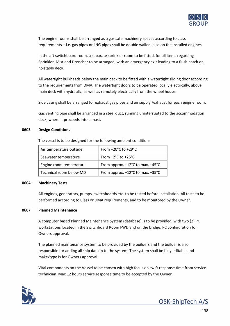
138
The engine rooms shall be arranged as a gas safe machinery spaces according to class
requirements – i.e. gas pipes or LNG pipes shall be double walled, also on the installed engines.
In the aft switchboard room, a separate sprinkler room to be fitted, for all items regarding
Sprinkler, Mist and Drencher to be arranged, with an emergency exit leading to a flush hatch on
hoistable deck.
All watertight bulkheads below the main deck to be fitted with a watertight sliding door according
to the requirements from DMA. The watertight doors to be operated locally electrically, above
main deck with hydraulic, as well as remotely electrically from the wheel house.
Side casing shall be arranged for exhaust gas pipes and air supply /exhaust for each engine room.
Gas venting pipe shall be arranged in a steel duct, running uninterrupted to the accommodation
deck, where it proceeds into a mast.
0603 Design Conditions
The vessel is to be designed for the following ambient conditions:
Air temperature outside From –20°C to +29°C
Seawater temperature From –2°C to +25°C
Engine room temperature From approx. +12°C to max. +45°C
Technical room below MD From approx. +12°C to max. +35°C
0604 Machinery Tests
All engines, generators, pumps, switchboards etc. to be tested before installation. All tests to be
performed according to Class or DMA requirements, and to be monitored by the Owner.
0607 Planned Maintenance
A computer based Planned Maintenance System (database) is to be provided, with two (2) PC
workstations located in the Switchboard Room FWD and on the bridge. PC configuration for
Owners approval.
The planned maintenance system to be provided by the builders and the builder is also
responsible for adding all ship data in to the system. The system shall be fully editable and
make/type is for Owners approval.
Vital components on the Vessel to be chosen with high focus on swift response time from service
technician. Max 12 hours service response time to be accepted by the Owner.
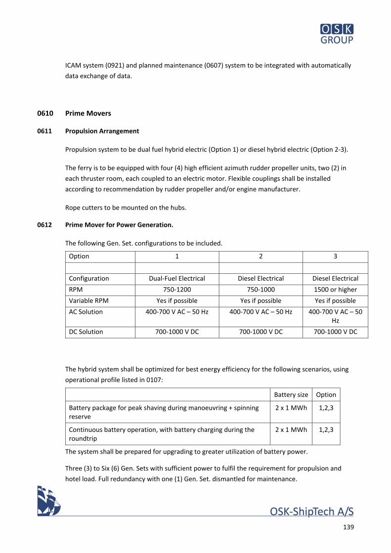
139
ICAM system (0921) and planned maintenance (0607) system to be integrated with automatically
data exchange of data.
0610 Prime Movers
0611 Propulsion Arrangement
Propulsion system to be dual fuel hybrid electric (Option 1) or diesel hybrid electric (Option 2‐3).
The ferry is to be equipped with four (4) high efficient azimuth rudder propeller units, two (2) in
each thruster room, each coupled to an electric motor. Flexible couplings shall be installed
according to recommendation by rudder propeller and/or engine manufacturer.
Rope cutters to be mounted on the hubs.
0612 Prime Mover for Power Generation.
The following Gen. Set. configurations to be included.
Option 1 2 3
Configuration Dual‐Fuel Electrical Diesel Electrical Diesel Electrical
RPM 750‐1200 750‐1000 1500 or higher
Variable RPM Yes if possible Yes if possible Yes if possible
AC Solution 400‐700 V AC – 50 Hz 400‐700 V AC – 50 Hz 400‐700 V AC – 50 Hz
DC Solution 700‐1000 V DC 700‐1000 V DC 700‐1000 V DC
The hybrid system shall be optimized for best energy efficiency for the following scenarios, using
operational profile listed in 0107:
Battery size Option
Battery package for peak shaving during manoeuvring + spinning reserve
2 x 1 MWh 1,2,3
Continuous battery operation, with battery charging during the roundtrip
2 x 1 MWh 1,2,3
The system shall be prepared for upgrading to greater utilization of battery power.
Three (3) to Six (6) Gen. Sets with sufficient power to fulfil the requirement for propulsion and
hotel load. Full redundancy with one (1) Gen. Set. dismantled for maintenance.
140
Power factor 0.8. (see also sect. 0811).
Each generator is driven by a 4‐stroke, turbocharged and inter‐cooled engine with direct injection
of liquid fuel and/or indirect injection of gas fuel. The engine to be operated in both Dual‐Fuel
(option 1 only) and diesel mode.
The Gen. Set. installation and all parts connected to the system, to be installed and equipped to
fulfil the requirements from DMA for an installation without separate emergency generator, two
redundant engine rooms, separated by min. one watertight compartment.
All pipes containing gas or LNG to be with double walls, when a dual‐fuelled engine is installed in a
“Gas Safe Machinery Space” (Option 1).
The engine and generator shall be built together on a common bed frame. Both engine and
generator set to be flexible mounted to foundation.
Generator sets shall be supplied as complete units from engine manufacturer.
Workshop Testing:
The engine shall be tested at the max continuous rating (MCR) in all fuel mode in maker’s
workshop in accordance with the requirements of the classification society and maker’s own
standard specification.
0613 Prime Mover, Equipment
The engines shall in general be equipped according to maker’s standards.
The Owner will accept the engines to be fitted without external standby pumps for cooling water,
lubrication oil etc.
HT cooling water system to be arranged for heat recovery for the central heating system – see
0746 & 0782.
Gas Valve Unit (Option 1):
For gas supply, each engine is supplied via a gas valve unit (GVU) in order to fulfil the safety
requirements set by the classification societies. The following main components are installed
inside a ventilated enclosure, which is to be mounted in a safe area:
Manual shut off valve with extension shaft
Fine filter
141
Double block and bleed valves
Gas pressure control valve
Nitrogen connection for inerting engine gas pipe
Instrumentation
The instrument cables and pneumatic tubing are installed and connected to skid mounted control cabinet(s).
Control and monitoring equipment on engine:
Microprocessor based distributed real time system for engine control and monitoring.
Hardwired interface with external systems for control functions such as remote start and stop.
Operator interface:
The operator’s interface to be based on a local control panel (LCP) built on the engine, consisting
of a display unit, backup indications and control switches & buttons.
All information from the LCP shall be read and monitored in the ICAM system and shown on a
mimic diagram.
The local display unit shall show all engine measurements (e.g. temperatures and pressures) and
provides various engine status indications as well as an event history
LNG / MGO operation (Option 1):
The necessary equipment for LNG and MDO operation to be supplied for each of the three (3) to
six (6) engines.
0614 Fuel Requirement.
Fuel oil quality:
The equipment is specified for fuel according to ISO 8217:2010 (ISO‐F‐DMA, max) with a viscosity
of max. 11 cSt/40°C.
Fuel GAS requirements (Option 1):
The engine is designed for continuous operation, without reduction in rated output, on natural
gas with the following properties (maximum/minimum values, content of gas at engine inlet):
Lower heat value, min. ¹) 28 MJ/Nm²)
Gas methane number, MN min 80
Methane content, min 70 vol.‐%
142
Hydrogen sulphide, max 0.05 vol.‐%
Hydrogen, max 3 vol‐%
Ammonia, max 25 mg/Nm3
Chlorine + Fluorines, max 50 mg/Nm3
Particles or solid content, max 50 mg/Nm3
Particles or solid size, max 5 μm
Gas inlet temperature 0‐60 °C
¹) the required gas feed pressure is dependent on the LHV
²) values given at Nm3 are at 0 ºC and 101.3 kPa.
The above MGO and LNG requirements are information received from a maker of dual fuel engines and should be understood as a guideline.
0618 Spare Parts and Tools
Spare parts in accordance with Class requirements for dual fuelled engines to be supplied.
1 set of engine manufacture’s standard tools for the supplied engines to be delivered
1 set of manufactures’ special tools for the supplied engines to be delivered.
0620 Propulsion System
0626 Azimuth Propeller Units
Four (4) high efficiency steerable thrusters to be installed, two (2) forward and two (2) aft.
The thrusters to be electrically driven with either fixed pitch or variable pitch propeller, Ice class C.
Port and starboard units shall have opposite direction of rotation.
Propellers shall be optimized for high efficiency and low noise level.
Technical Data:
Power applied to input shaft Min. 1250 kW
Input speed Depending on supplier
Service factor/torque load Continuous operation
Total gear reduction Depending on supplier
Stem length To be determined
Propeller type twin F.P.‐ or single C.P., scewed blades, matched
Propeller material Cu Al 10 % Ni
143
Propeller diameter Approx. 2m ‐ subject to tank test and optimization by maker
Propellers shall not protrude bottom line of vessel, incl. dead rise
Further Features:
Streamlined and optimised lower casing
Installation well cover for bolted mounting from above.
Bottom plate to be streamlined, fitted to hull shape (by shipyard)
Power Transmission:
Electric motors shall be connected to rudder propeller units with elastic couplings.
0627 Propeller Control Equipment
The control system consists of the following sub‐systems:
Full follow‐up electric steering system, including a time‐dependent back‐up‐system, consisting of:
Two (2) electric motors mounted on the upper gearbox
steering time about 15 sec/180°.
Frequency control for steering motors
Rudder propellers shall be steerable 360º continuous
Propeller rpm shall be stepless controllable from zero to full RPM (depending on system)
Units shall be steerable independent of revolutions with propeller revolutions from zero to full RPM
Electronic System:
One (1) electronic cabinet with exchangeable printed circuit boards, located in each thruster compartment
digital logic, programmable (EPROMs), RS 232 interface
24 V DC main power supply (rest ripple <1V)
interface autopilot system
potential‐free alarm contacts, basically:
lub oil level STP low
hydraulic oil level low
failure way‐dependent steering system
144
failure way‐dependent speed control system alarm contacts according to final design of system
Control Panels:
Four (4) drop‐in control panels to be installed in the two (2) CL steering positions and in the two
(2) bridge wing position, each for control of the four (4) thrusters, protection IP 44.
The control panels are basically equipped as follows:
Double co‐pilot control handles for one‐hand steering + speed control
Crash‐stop function, turning all units 180º (outward)
Sailing mode/harbour mode switch over function. Harbour mode: turning one set of rudder propellers 180º (outward), Sailing mode: limiting rudder angle.
Joystick system with best optimization of engine power for stopping and manoeuvring capabilities. It must be possible turn the vessel around midships axis, and both ends axis.
Thrust direction indicators for all four units
Controls for back‐up (emergency) steering system
Controls for back‐up (emergency) engine speed control system
Push buttons for take over control, (the steering positions are not in line of sight)
Push buttons for autopilot mode at both steering positions
Dimmer
Joystick + manual control (connected 2+2)
0629 Spare Parts and Tools
Spares in accordance with Class requirements for four (4) azimuth propeller units to be supplied.
One (1) spare propeller of each type – One (1) Push and one (1) Pull
One (1) set of manufacture’s standard tools for the supplied azimuth propeller units to be
delivered
0640 Auxiliary Boilers
0642 Oil Fired Central Heating Boiler
See also 0782.
No oil‐ or gas boiler shall be fitted.
Heating of all spaces shall be by waste heat recovery or heat pumps.
145
In case of ventilation is chosen according to 0512 alternative 2, electric heating elements to be
included in the system as backup for heating during dry docking periods in winter time.All
necessary temperature sensors, shunt valves, thermostat regulations, expansion tanks etc. to be
installed for fully automatically operation. The boiler to be connected to the ICAM system.
0646 Exhaust Gas Boiler
See also 0733‐3.
Two (2) high performance exhaust gas heat exchangers for waste heat recovery to be mounted in
the aft casing and connected to the two (2) Gen. Sets in the aft engine room. Dry running mode
shall be possible.
Soot blower rings using compressed air/water to be included.
Exhaust gas boiler to be arranged for easy inspection and cleaning.
0650 LNG System (Option 1 only)
0651 LNG Storage System
The LNG gas storage system shall be designed according to the International Code of Safety for
Ships Using Gases or Other Low‐Flashpoint and relevant class rules.
The LNG gas storage system shall be based on a double shelled perlite and vacuum insulated LNG
tank. The LNG tank insulation to be sufficient to keep the gas in liquid state for a period according
to the requirements from the Class.
LNG shall be bunkered through bunkering station via an insulated pipe double walled pipe in
ventilated trunk. The bunker line shall be purged gas‐free after bunkering.
Bunkering is not intended to take place with passengers on board.
Interface to shore bunkering facilities is carried out with a flexible hose connection.
LNG tank to be supplied with an on‐mounted tank connection space (cold box) at the side/end of
the tank. The cold box contains all pipe and ventilation penetrations through the tank shell as well
as heating media connections (glycol/water) to LNG evaporators.
The LNG storage tank main technical data as follow:
Tank type Double shelled cylindrical
146
Insulation Perlite and vacuum insulated
Location Below deck
Geometric volume 63 m3
Net volume 95% 60 m3
The tank shall be supported for acceleration forces in all directions.
Vacuum insulated LNG tank
The cryogenic LNG tank is an independent tank, type C, designed in accordance with the IGC code,
chapter 4.
The inner tank, which contains the liquid LNG shall be manufactured of austenitic stainless steel.
The outer vessel to be made of austenitic stainless steel with the annulus space filled with perlite.
The annulus is evacuated to vacuum to minimize heat transfer from the ambient. The outer tank
is designed to withstand full under pressure.
Perlite is neither combustible nor toxic and has a good insulation even if the vacuum in the annual
space would be lost.
All welds on the inner tank to be 100% X‐rayed.
The cryogenic inner tank to be designed for the following conditions:
Inner tank material Austenitic stainless steel
Inner tank design pressure (max) 9.0 bar(g)
Inner tank design under pressure (max) 0.7 bar(g)
Design temperature (for nitrogen test) ‐196 °C
Maximum tank temperature +50 °C
LNG tank mounting Horizontal
0652 LNG Pipes
LNG pipes between bunker station and cold box to be insulated double wall pipes or pipes in
ventilated trunk. LNG/ gas pipes between cold box and GVU to be double walled pipes.
Double walled pipes have to be ventilated ‐ 30 air changes pr. hour.
Ventilation has to be by extraction, and inlet/outlet positions from free air to be according to the
IGF code.
Ventilation of double walled pipes or trunks have to be independent of other ventilation systems.
147
Trunks with LNG pipes has to be ventilated ‐ 30 air changes pr. hour. and inlet/outlet positions
from free air to be according to the IGF code.
0653 LNG Bunker Station
The LNG bunker station shall include connection to one bunkering line (LNG), one vapour return
line (if so required by authorities) and one nitrogen purging line with respective control /thermal
relief valves and flanges.
The return line is used in case the bunkering operation takes place with two hoses connected and
the evaporated gas is returned to the bunkering terminal, truck or barge.
LNG bunker system to be optimized for shortest possible bunker time.
Pressure relief line to be fitted according to the Class requirement.
Ventilation Natural
Gas/LNG pipes Insulated austenitic stainless steel
Main valves Pneumatic/membrane type
Interface (hose excluded) Flexible hose connection flange
Drip trays of stainless steel shall be fitted below the bunkering connections and where leakage
may occur. Drain over the ship's side without contact with hull structure to be ensured, if required
by class. Bulkhead fire insulation A60.
The bunker station shall be arranged at car deck level amidships, port side
A winch with hoisting wire, and skid for supporting hoses shall be arranged inside bunker station
shipside door. Gas valves and flanges shall be 800 mm from ships side.
Local Control Station at Bunker Station:
At the bunker station, a local control panel is to be located in a safe location minimum 3 m from
the bunker station.
From the local control panel the tank pressure and tank level can be monitored.
An audible alarm is installed on the control panel.
148
0660 Engine Room Outfit & Equipment
0662 Floor Plates, Platforms, Grating
The floors, platforms and ladders to be arranged in order to give a convenient access to
machinery in order to permit inspection, local operation, maintenance and repair space for all
machinery, valves etc. and for entrance to and escape from the machinery space.
Platforms to be finally approved by Owner when installed on board. Minor hinged hatches giving
access to valve etc. below the platform level is accepted by the Owner.
The floor plates to be of non‐slip type (4‐5 mm tear plates or similar). Floor plates to have
coaming along the sides and around openings. Hatches (flush) to be provided for essential items
below. Floor plates to be secured by stainless screws.
Floor plates and boundary bars to be of steel in escape routes, aluminium elsewhere as per
approval by authorities. Vertical supports attached to hull structure to be of steel. Machinery is
not to be used to support floor plates. Plates to be divided into sections small enough for easy
handling.
Floor to run continuously with inclination through all engine compartments with no steps.
Adequate number and size of stair and ladders to be arranged for convenient access to all decks,
platforms, casing and funnel.
Stairs and ladders to be made of steel. The treads of sloping ladders are to be of approved pattern
and designed to provide a durable non‐slip surface. All sloping ladders to be fitted with a screen
plate below.
Ladders, gratings and platforms to be provided with handrails with smooth surface and flush
joints.
Platforms for maintenance and repair of main and auxiliary engines to be arranged according to
engine maker’s recommendation. For machinery, valves etc. located below floor plates,
inspection covers to be arranged with identification marks.
0664 Guards & Rails
Guards and rails to be fitted to ensure safe working areas and access to all equipment
All rotating parts e.g. fly wheels, pump shafts, etc. are to be screened off to prevent accidents.
Hand‐rails are to be fitted as necessary.
149
0665 Insulation of Machinery
General ‐ Insulation acc. to Class requirement. Insulation below main deck to be covered with
steel plate according to Owners requirements.
Control room to be sound insulated according to DMA requirements.
Workshop to be sound insulated according to Owners requirements.
All hot surfaces at machinery to be isolated or screened for the safety of personnel.
Pipes in general to be insulated according to 0526.
0666 Drip Trays
Drip trays to be provided below components where oil and/or water spill will occur.
Drip trays for contaminated water to be drained into sludge tank.
Drip trays for pure Lubricating oil/MGO to be drained into waste oil tank.
Drip trays to be arranged in front of all MGO settlings‐, storage‐ and service tanks where the
connecting valves are located.
0667 Waste Containers
Two (5) steel waste container for cotton waste and two (5) for oily waste etc. with hinged cover of
suitable portable size to be provided on the engine floor and close to the working areas.
0670 Maintenance & Repair Facilities
0671 Workshop with Equipment
One (1) mechanical workshop to be arranged and one (1) blacksmith workshop to be arranged in
the same room.
The room to be equipped with the following tools:
One (1) 2 m work bench with vice and pipe clamp
One (1) bench grinding machine, 2xØ200 mm grindstone (fine/rough), 400 V motor
One (1) vertical power drill with conus 3 and 16 mm drill chuck
One (1) tool board
Four (4) tool lockers
150
One (1) pipe rack (min 6 m)
One (1) steel rack with plastic drawers for small spare parts
One (1) welding machine, 150A, portable
One (1) Tig welding machine, portable
One (1) Welding table
One (1) lathe, Ø700/Ø400/Ø70, length 1500 mm
One (1) of Gen. Set. supplier approved test bench for MGO valves
One (1) Hand tools and electric tools for a lump sum of EUR 10,000 Owners free choice.
One (1) of Gen. Set. supplier approved test bench for MGO valves
Make and type of all the above listed items for Owners approval.
Final arrangement of workshop for Owners approval.
One (1) separate welding area to be arranged with heavy duty welding curtains.
One (1) ventilated cleaning room with shelves for chemicals, fitted with:
One (1) part washer machine, hot/cold water, chemical, soap, pressure air, ventilation
One (1) ultra sonic tub
One (1) steel tub for cleaning The room must be watertight and connect to the daily bilge system
Make and type of all the above listed items for Owners approval.
One (1) stores room to be fitted with twelve (12) heavy duty steel lockers for convenient stowing
of spares. Engine stores room bulkheads may be of light construction. Rack for cables etc. to be
fitted inside the stores room.
One (1) electrical work shop to be arranged. The room to be equipped with the following tools:
One (1) 2 m work bench
One (1) electrical test bench according to Owners requirement.
1 Hand tools and electric tools for a lump sum of EUR 5000 Owners free choice.
Make and type of all the above listed items for Owners approval.
0675 High Pressure Cleaning System
One (1) high pressure cleaner system with eight (8) taps to be permanently installed for owners
approval. All taps shall be anti‐freeze type. All taps to be provided with quick coupling for DN 20
hose. The system to be connected to both hot/cold water with non‐return valve.
Eight (8) hose wheels to be fitted near the taps. Each hose to be twenty (20) m long. Hose wheel
to be mounted inside a GRP hose cabinet.
151
All connections to be with ball valve and quick coupling incl. protecting cover.
0677 Lifting Gears and Transfer Arrangement
Four (4) lifting beams provided with manual operated trolley and manual chain hoist, to be
arranged above the Gen. Set. SWL = 500 kg.
One (1) lifting beam and trolley with manual chain hoist to be arranged for replacing Nitrogen
Bottle battery, from stowed position to engine room flush hatch (Option 1 only).
One (1) wall mounted jib crane to be fitted in the workshop, with electrical chain hoists, SWL =
500 kg
One (1) SWL 1000 kg lifting point to be fitted below the hoistable deck, right above the deck hatch
for the workshop, arranged with SWL 1000 kg electrical chain hoist.
One (1) SWL 1000 kg lifting point to be fitted above the platform lift for engine stores SWL 1000
kg electrical chain hoist.
Twenty‐five (25) lifting points (SWL 500 kg) to be fitted above heavy components in the engine
room according to instructions. Four (4) manual chain hoists to be supplied.
One (1) SWL 1000 kg lifting beam and trolley to be arranged from engine room fwd to engine
room aft.

152
153
70 Machinery System
170580.0131.01
Date 16.05.18
Sign URT
154
70 Machinery Systems
All stated capacities are preliminary figures, and shall be recalculated by the shipyard during the
detailed design, for obtaining the approval of the Classification society and DMA.
0700 Markings & Identification
0701 Tank Identification
All tanks in machinery spaces to be clearly marked with a nameplate of adequate size, indicating
the capacity and content type in the tank. Plate to be of brass, with black letters and English
language.
0702 Pipe Colour Schedule
After final painting, all pipe system to be marked to Owner’s standard with coloured tapes “Flo‐
code” or equivalent. Direction of flow to be indicated with arrows.
0703 Name Plates for Machinery
All machinery components to be marked according to List of Machinery Equipment.
A brass nameplate with English language and black letter to be fitted on each component, size to
be agreed.
List of Machinery Equipment to be supplied to the vessel as a part of “Engine room delivery
booklet”. Name of supplier, address, phone no. and E‐mail address to be added on the list
Original nameplate on engine room components to be retained, with Information such as:
Indication number
Name of component
Name of manufacture
Type
Size, Capacity, RPM etc.
Serial number / Fabrication year
Electrical power
0704 Label Plates for Valves & Fittings
All valves and armatures etc. to be marked according to List of Valves and Armatures.
155
A brass plate with English language and black letter to be fitted on each valve and armature etc,
size and form to be agreed.
List of Valves and Armatures to be supplied to the vessel as a part of “Engine room delivery
booklet”
Information on the plate for valve and armature etc.:
Indication number
Function of valve
0705 Label Plates on Operation Panels
Sufficient labels to be mounted in frames and placed in suitable location.
Instructions boards according to Owner’s requirements
0706 System Diagrams Mounted on Board
As built piping diagrams in laminated plastic covers or equal to be placed in the ECR and in both
engine rooms.
Size and numbers to be agreed.
Diagram symbols to be enclosed in each piping diagram.
0710 Piping System, General Requirements
0711 Piping System Layout, General
In general, piping to be dimensioned according to the fluid handled with respect to viscosity,
temperature, pressure, pressure surges, total pipe length, frictional losses due to pipes, valves
and fittings, static suction lift and discharges. The velocity of liquids and gases in the systems to be
in a range used for normal shipbuilding practice and according to 0522.
Where practical, the pipe to be routed to permit normal radius elbows (1.5D) and have expansion
loops to take up expansion. Alternatively, expansion joints of approved type to be used. Pipes
mounted to equipment, subject to vibration motions or thermal expansion, to be fitted with class
approved flexible connections.
All piping to be routed to provide simple, neat and economical layout allowing for easy supporting
and access. If not specified otherwise, piping systems to be provided with flanges at regular
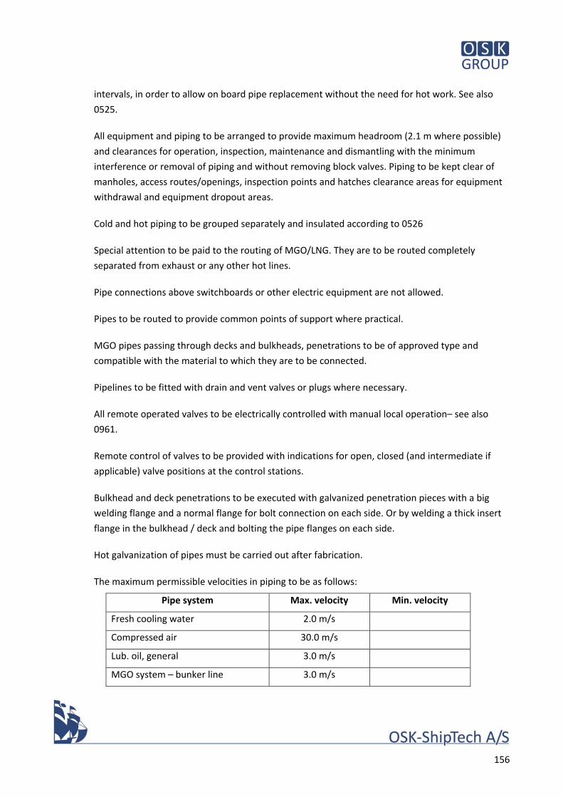
156
intervals, in order to allow on board pipe replacement without the need for hot work. See also
0525.
All equipment and piping to be arranged to provide maximum headroom (2.1 m where possible)
and clearances for operation, inspection, maintenance and dismantling with the minimum
interference or removal of piping and without removing block valves. Piping to be kept clear of
manholes, access routes/openings, inspection points and hatches clearance areas for equipment
withdrawal and equipment dropout areas.
Cold and hot piping to be grouped separately and insulated according to 0526
Special attention to be paid to the routing of MGO/LNG. They are to be routed completely
separated from exhaust or any other hot lines.
Pipe connections above switchboards or other electric equipment are not allowed.
Pipes to be routed to provide common points of support where practical.
MGO pipes passing through decks and bulkheads, penetrations to be of approved type and
compatible with the material to which they are to be connected.
Pipelines to be fitted with drain and vent valves or plugs where necessary.
All remote operated valves to be electrically controlled with manual local operation– see also
0961.
Remote control of valves to be provided with indications for open, closed (and intermediate if
applicable) valve positions at the control stations.
Bulkhead and deck penetrations to be executed with galvanized penetration pieces with a big
welding flange and a normal flange for bolt connection on each side. Or by welding a thick insert
flange in the bulkhead / deck and bolting the pipe flanges on each side.
Hot galvanization of pipes must be carried out after fabrication.
The maximum permissible velocities in piping to be as follows:
Pipe system Max. velocity Min. velocity
Fresh cooling water 2.0 m/s
Compressed air 30.0 m/s
Lub. oil, general 3.0 m/s
MGO system – bunker line 3.0 m/s
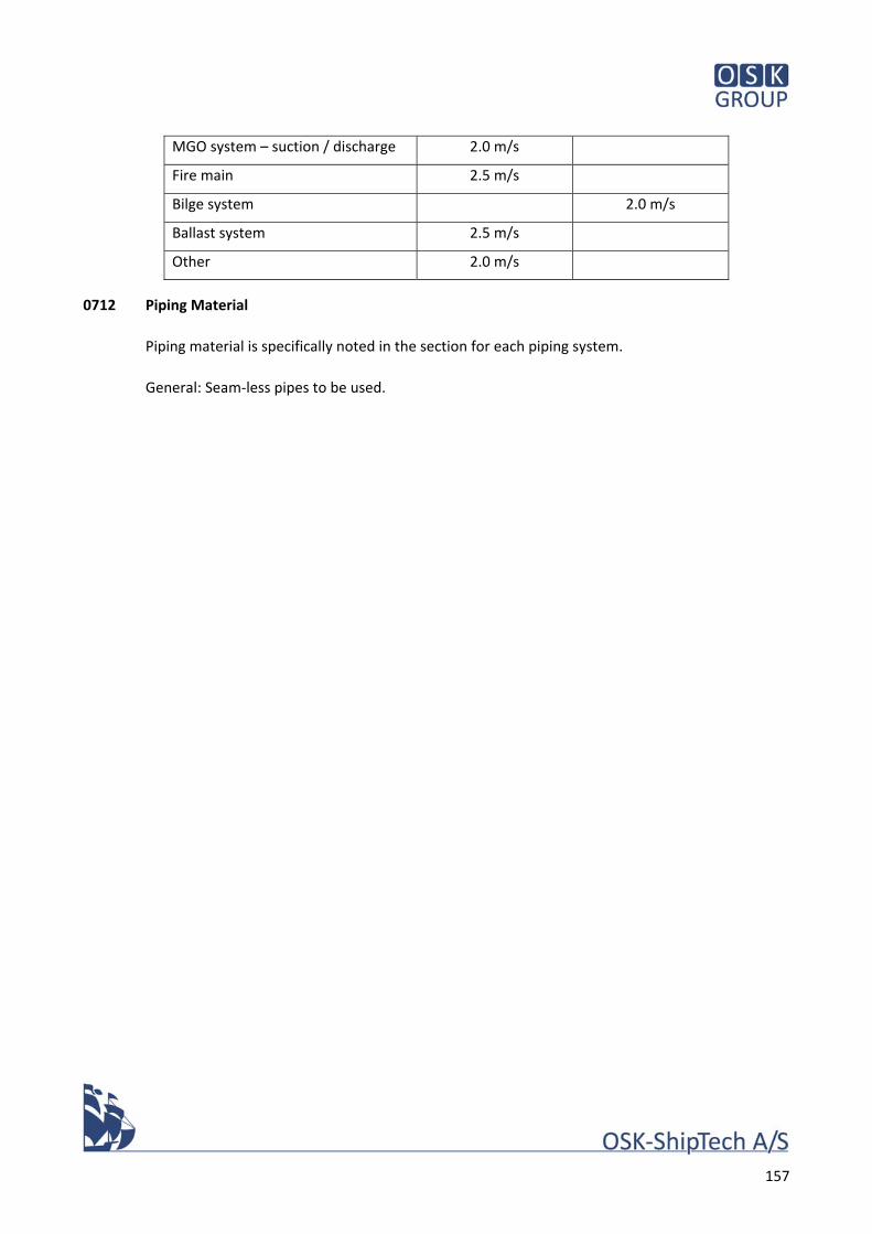
157
MGO system – suction / discharge 2.0 m/s
Fire main 2.5 m/s
Bilge system 2.0 m/s
Ballast system 2.5 m/s
Other 2.0 m/s
0712 Piping Material
Piping material is specifically noted in the section for each piping system.
General: Seam‐less pipes to be used.
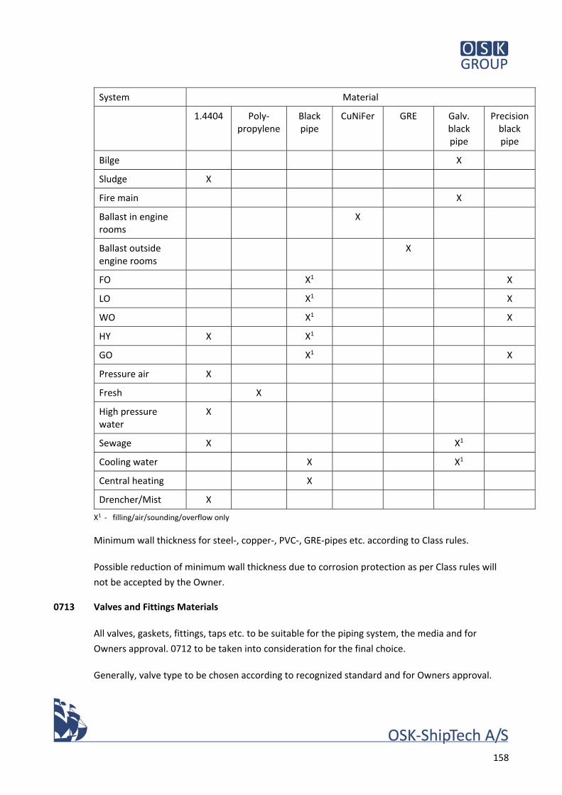
158
System Material
1.4404 Poly‐propylene
Black pipe
CuNiFer GRE Galv. black pipe
Precision black pipe
Bilge X
Sludge X
Fire main X
Ballast in engine rooms
X
Ballast outside engine rooms
X
FO X1 X
LO X1 X
WO X1 X
HY X X1
GO X1 X
Pressure air X
Fresh X
High pressure water
X
Sewage X X1
Cooling water X X1
Central heating X
Drencher/Mist X
X1 ‐ filling/air/sounding/overflow only
Minimum wall thickness for steel‐, copper‐, PVC‐, GRE‐pipes etc. according to Class rules.
Possible reduction of minimum wall thickness due to corrosion protection as per Class rules will
not be accepted by the Owner.
0713 Valves and Fittings Materials
All valves, gaskets, fittings, taps etc. to be suitable for the piping system, the media and for
Owners approval. 0712 to be taken into consideration for the final choice.
Generally, valve type to be chosen according to recognized standard and for Owners approval.
159
All pipes to be marked according to 0702.
0714 Piping Connection & Support
Typical joints approved by the Owner: welding, flange, compression, straub, Johnson, collar.
Thread joints are also accepted, but number to be minimized.
Generally, the joint must be suitable for the pipe material, pipe size and the media.
Generally, joints to be made of the same material as the pipe, or as per agreement with the
Owner.
Generally, steel pipes of 50 mm diameter and above to be joined with flanged connections or as
per agreement with the Owner. Cast fitting for joint below 50 mm will be accepted.
Hydraulic high pressure pipes, and other pipes transmitting noise and vibration, to be supported
with resilient supports and deck‐ and bulkhead penetration to be resilient.
All pipes to be suitably supported according to recognized standard.
Threads in general to be metric.
0715 Insulation of Pipes
All hot surfaces of machinery, piping and tanks having normal operating fluid temperature above
50, except cooling water system and where otherwise described hereinafter, to be insulated in
accordance with following specifications.
All hot and cold sanitary water pipes to be insulated with mineral wool against heat loss or
sweating.
The insulation shall normally not cover flanges, valves and fittings.
Cold pipes (for refrigeration) to be insulated by Armaflex, rubber foam or equal, incl. valves and
armatures.
All pipes, pressure and drain pipes, exposed to free deck carrying water have to be insulated and
electric heat traced, unless other is agreed.
In exposed or visible positions, pipe insulation to be clad with stainless steel.
In all cases, where pipe insulation abuts flanges and fittings, the end of insulation to be suitably
terminated to permit free removal of bolts and/or to allow movement of pipes at hangers.
160
0716 Protection of Pipes
All pipes to be properly fastened to the ship's structure with clamps and similar. Where exposed
to mechanical wear and tear, pipes to be suitably protected.
Where relevant, pipes to be flexibly mounted for noise reduction and fatigue protection.
Expansion bends and/or flexible couplings to be used where pipes are exposed to stresses due to
temperature variations and due to hull deflections.
0717 Valves, Quick Closing Device
Quick closing valves of approved type to be mounted on oil tanks according to regulations.
Necessary control valves and operation instructions will be placed close to emergency stops and
fire control station.
The valves to be operated pneumatically..
Operator station shall be placed on the bridge.
0718 Piping, Fittings & Valves
Where possible, the same make and type of valve is to be used for all similar valves in the vessel.
See also 0713
All valves, gaskets, fittings, taps etc. to be suitable for the piping system, the media and for
Owners approval.
Valves, cocks, flanges, bolts and nuts are to be in accordance with ISO/EN. Material of machinery
and equipment are to be in accordance with Builder’s standard and/or Manufacturer’s standard.
Remote controlled valves:
Bilge, ballast and heeling tank valves to be remote controlled from ICAMS.
Valves MDO transfer system to be remote controlled from ICAMS.
Valves FW bunker system to be remote controlled from ICAMS.
Valves sewage system to be remote controlled from ICAMS.
Valves fire system to be remote controlled from ICAMS.
Valves drencher to be remote controlled from ICAMS.
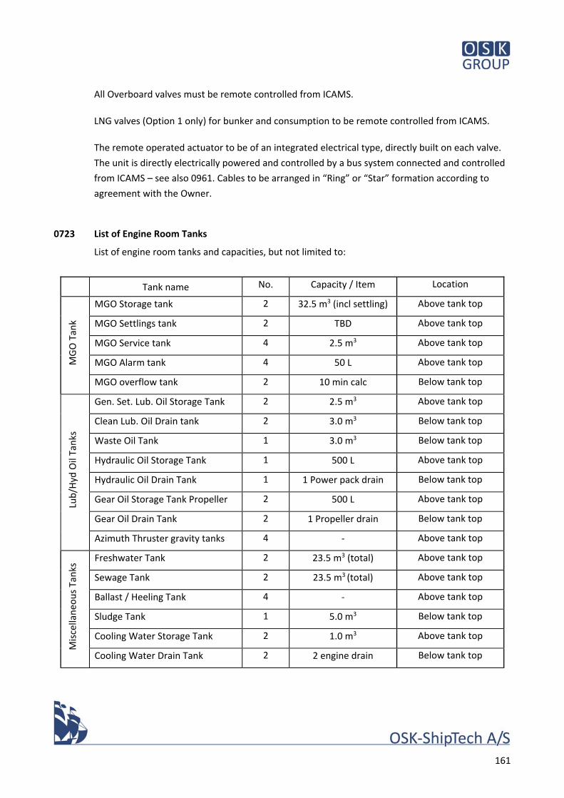
161
All Overboard valves must be remote controlled from ICAMS.
LNG valves (Option 1 only) for bunker and consumption to be remote controlled from ICAMS.
The remote operated actuator to be of an integrated electrical type, directly built on each valve.
The unit is directly electrically powered and controlled by a bus system connected and controlled
from ICAMS – see also 0961. Cables to be arranged in “Ring” or “Star” formation according to
agreement with the Owner.
0723 List of Engine Room Tanks
List of engine room tanks and capacities, but not limited to:
Tank name No. Capacity / Item Location
MGO Tan
k
MGO Storage tank 2 32.5 m3 (incl settling) Above tank top
MGO Settlings tank 2 TBD Above tank top
MGO Service tank 4 2.5 m3 Above tank top
MGO Alarm tank 4 50 L Above tank top
MGO overflow tank 2 10 min calc Below tank top
Lub/H
yd Oil Tanks
Gen. Set. Lub. Oil Storage Tank 2 2.5 m3 Above tank top
Clean Lub. Oil Drain tank 2 3.0 m3 Below tank top
Waste Oil Tank 1 3.0 m3 Below tank top
Hydraulic Oil Storage Tank 1 500 L Above tank top
Hydraulic Oil Drain Tank 1 1 Power pack drain Below tank top
Gear Oil Storage Tank Propeller 2 500 L Above tank top
Gear Oil Drain Tank 2 1 Propeller drain Below tank top
Azimuth Thruster gravity tanks 4 ‐ Above tank top
Miscellaneo
us Tanks Freshwater Tank 2 23.5 m3 (total) Above tank top
Sewage Tank 2 23.5 m3 (total) Above tank top
Ballast / Heeling Tank 4 ‐ Above tank top
Sludge Tank 1 5.0 m3 Below tank top
Cooling Water Storage Tank 2 1.0 m3 Above tank top
Cooling Water Drain Tank 2 2 engine drain Below tank top
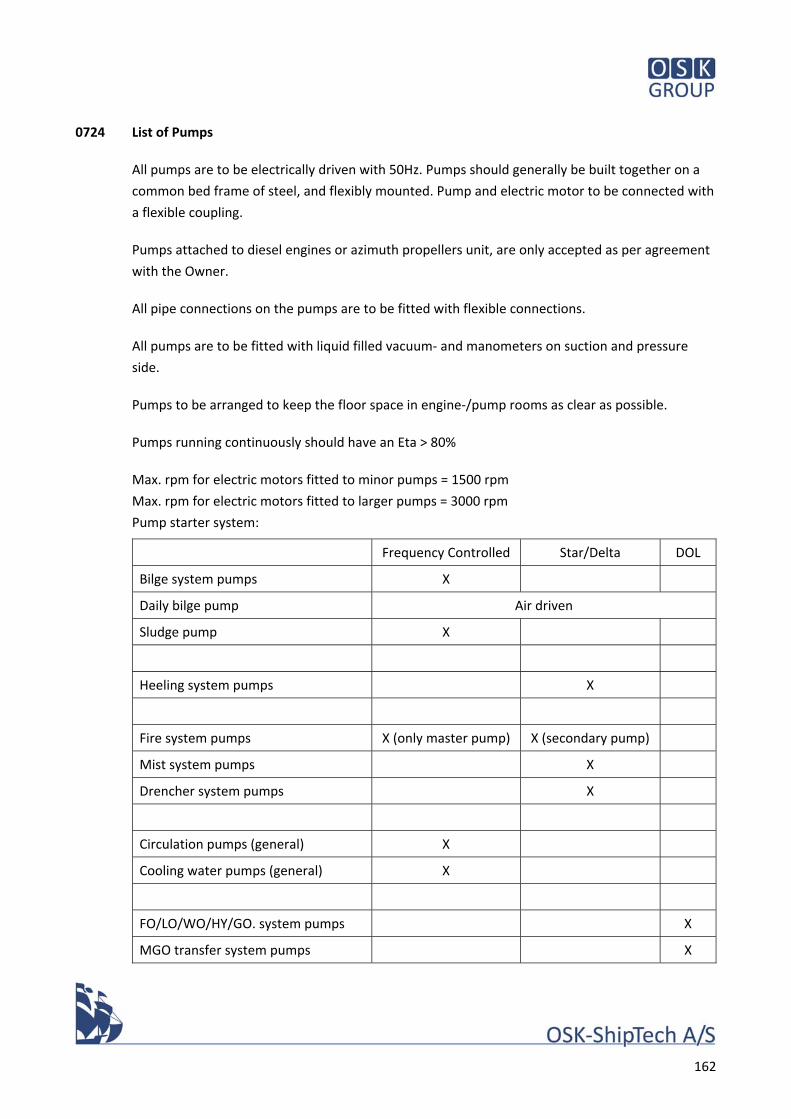
162
0724 List of Pumps
All pumps are to be electrically driven with 50Hz. Pumps should generally be built together on a
common bed frame of steel, and flexibly mounted. Pump and electric motor to be connected with
a flexible coupling.
Pumps attached to diesel engines or azimuth propellers unit, are only accepted as per agreement
with the Owner.
All pipe connections on the pumps are to be fitted with flexible connections.
All pumps are to be fitted with liquid filled vacuum‐ and manometers on suction and pressure
side.
Pumps to be arranged to keep the floor space in engine‐/pump rooms as clear as possible.
Pumps running continuously should have an Eta > 80%
Max. rpm for electric motors fitted to minor pumps = 1500 rpm
Max. rpm for electric motors fitted to larger pumps = 3000 rpm
Pump starter system:
Frequency Controlled Star/Delta DOL
Bilge system pumps X
Daily bilge pump Air driven
Sludge pump X
Heeling system pumps X
Fire system pumps X (only master pump) X (secondary pump)
Mist system pumps X
Drencher system pumps X
Circulation pumps (general) X
Cooling water pumps (general) X
FO/LO/WO/HY/GO. system pumps X
MGO transfer system pumps X
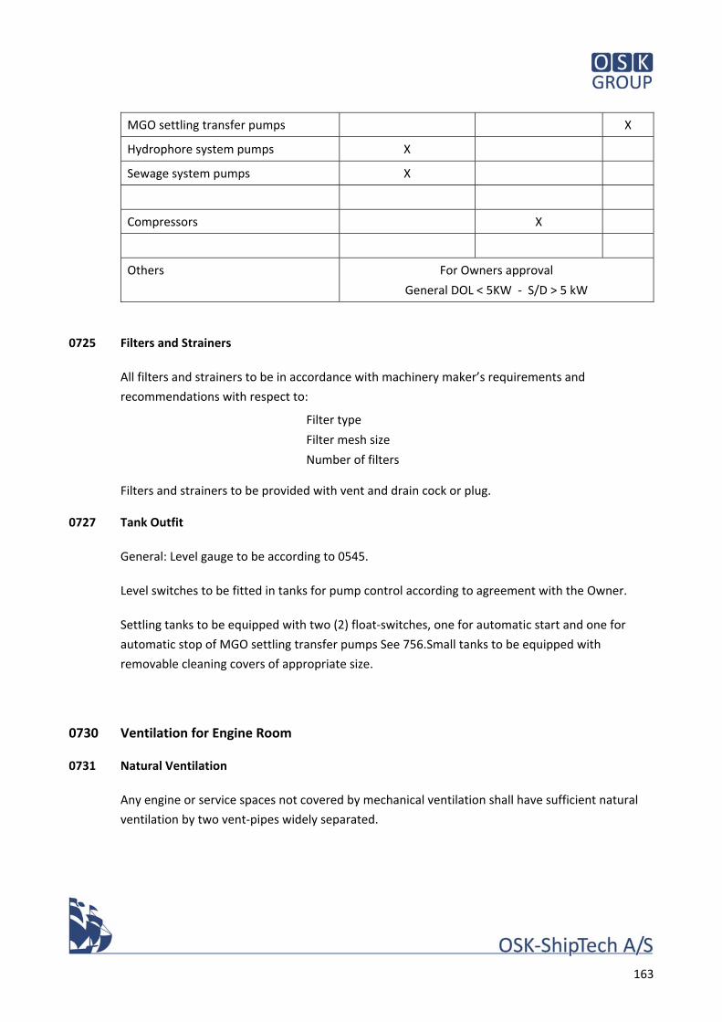
163
MGO settling transfer pumps X
Hydrophore system pumps X
Sewage system pumps X
Compressors X
Others For Owners approval
General DOL < 5KW ‐ S/D > 5 kW
0725 Filters and Strainers
All filters and strainers to be in accordance with machinery maker’s requirements and
recommendations with respect to:
Filter type
Filter mesh size
Number of filters
Filters and strainers to be provided with vent and drain cock or plug.
0727 Tank Outfit
General: Level gauge to be according to 0545.
Level switches to be fitted in tanks for pump control according to agreement with the Owner.
Settling tanks to be equipped with two (2) float‐switches, one for automatic start and one for
automatic stop of MGO settling transfer pumps See 756.Small tanks to be equipped with
removable cleaning covers of appropriate size.
0730 Ventilation for Engine Room
0731 Natural Ventilation
Any engine or service spaces not covered by mechanical ventilation shall have sufficient natural
ventilation by two vent‐pipes widely separated.
164
0732 Mechanical Ventilation
The two engine rooms to be provided with mechanical ventilation with natural exhaust through a
rainproof grid on outboard side of each casing. Openings in the outlet grids to be calculated to
allow escape 75% of the inlet air in accordance with the limited velocity. Engine room ventilation
intakes shall be located at inboard side of Funnel Casing.
All engine spaces must be with mechanical ventilation.
Engine suppliers recommendation for air exchange inside the engine room to be followed.
Both switchboard rooms must be equipped with a packaged air conditioner unit, with fresh air
supply and recirculation. The unit shall be capable of cooling by compressor, and sea water via
heat exchanger. Heating by waste heat recovery system.
Noise level of ventilation louvres shall not exceed 70 dBA at 1.0 m. distance.
Fire dampers to be operated outside the casing and ventilator room.
Fire dampers to be automatically operated for the casing and the ventilator rooms.
Ventilation of engine space to be arranged with slight over‐pressure and the temperature raise
between inlet and outlet to be max. 12,5°C.
Two (2) electrically driven axial fans to be installed for supplying air to each engine room.
Ventilation capacities for engine to be calculated according to ISO ‐8861 as a guidance.
The electric motor for the fans have to be rpm controlled by frequency converter, air flow
controlled by temperature sensor placed in exhaust air flow and a pressure sensor.
The fans have to be controlled from ICAMS and local.
The fans to be located accessible and built together with fire dampers. Fire dampers to be remote
controlled and automatically reopened after restoring the power.
Engine room outlet air louvre shall be equipped with volume control and controlled together with
volume control of engine room ventilation.
Vent outlets in engine room shall be manually adjustable in volume and direction.
Air intakes for engine rooms ventilation shall be fitted with stainless steel louvre, demister of
extruded plastic sleeves. Intakes must be fitted with filters (bag‐type), filters must be arranged for
easy replacement.
165
Engine room vent openings to fulfil DMA requirements to height and location, and shall not be
fitted with closing appliances other than for fire. Fire dampers shall be automatic, with motor and
self‐closing devises. The fire dampers shall open automatic after return power, ore event of
blackout.
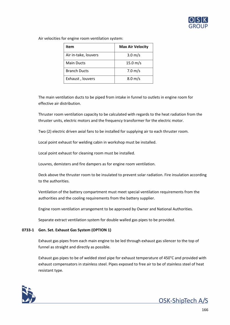
166
Air velocities for engine room ventilation system:
Item Max Air Velocity
Air in‐take, louvers 3.0 m/s
Main Ducts 15.0 m/s
Branch Ducts 7.0 m/s
Exhaust , louvers 8.0 m/s
The main ventilation ducts to be piped from intake in funnel to outlets in engine room for
effective air distribution.
Thruster room ventilation capacity to be calculated with regards to the heat radiation from the
thruster units, electric motors and the frequency transformer for the electric motor.
Two (2) electric driven axial fans to be installed for supplying air to each thruster room.
Local point exhaust for welding cabin in workshop must be installed.
Local point exhaust for cleaning room must be installed.
Louvres, demisters and fire dampers as for engine room ventilation.
Deck above the thruster room to be insulated to prevent solar radiation. Fire insulation according
to the authorities.
Ventilation of the battery compartment must meet special ventilation requirements from the
authorities and the cooling requirements from the battery supplier.
Engine room ventilation arrangement to be approved by Owner and National Authorities.
Separate extract ventilation system for double walled gas pipes to be provided.
0733‐1 Gen. Set. Exhaust Gas System (OPTION 1)
Exhaust gas pipes from each main engine to be led through exhaust gas silencer to the top of
funnel as straight and directly as possible.
Exhaust gas pipes to be of welded steel pipe for exhaust temperature of 450°C and provided with
exhaust compensators in stainless steel. Pipes exposed to free air to be of stainless steel of heat
resistant type.
167
The exhaust gas system to be resilient mounted and thermally/acoustically insulated from the
ship structure.
Water trap with drain cock to be installed in each exhaust gas system to prevent the ingress of
water into the main engine. Drains shall terminate in engine room bilge wells.
All connections to main engine, compensators, and silencer to be with flanges.
Back pressure to be calculated and shall not exceed the engine makers recommendations.
Arrangement in the top of funnel to be approved by owner.
0733‐2 Gen. Set. Exhaust SCR System (OPTION 2‐3)
All three (3) to six (6) Gen. Set. are each fitted with a complete SCR system for IMO III (alternative
EGR):
Two (2) UREA tanks
Three (3) to Six (6) UREA supply pumps
Three (3) to Six (6) UREA units control
Three (3) to Six (6) UREA Dosing units
Three (3) to Six (6) UREA Mixing units
Three (3) to Six (6) SCR Units
The SCR system shall be as compact and simple as possible, easy maintenance is a requirement.
The SCR shall not occupied more than 20% of the space in the casing.
0733‐3 Waste Heat Recovery System
One (1) Waste Heat Recovery system for electrical production with Gen. Set. exhaust. The system
shall be located near the aft engine room and shall be connected to both Gen. Set. in the aft
engine room.
The WHR shall be connected to the main switchboard with necessary switchboards, transformers,
inverters, cooling water equipment etc.
0734 Exhaust Silencer for Gen Sets
Exhaust gas systems for Gen. Set. to be equipped with silencers, where noise reduction is
adjusted to suit the engine make and type.
The size of the individual silencer is to be calculated such that the noise level can be reduced to
max. 85 dB(A), measured at 1 metre’s distance from outlet and max. 80 dB(A) measured on car
deck.
168
Frequency distribution calculation is to be carried out for the following frequencies:
31.5 / 63 / 125 / 250 / 500 / 1000 / 2000 / 4000 / 8000 / 16000 Hz.
No clear tones should be audible in the reduced noise. Clear tones are defined as a noise level at a
frequency which exceeds the noise level on other frequencies by 10 dB or more.
In determining dimensions, special attention should be given to max. permissible counter
pressure for the engine and max. exhaust speed of 50 m/s in the actual silencer.
Installation:
Silencers be positioned as close to the engine as possible.
Necessary exhaust compensators are to be built into the exhaust system, both with regard to
thermal expansion and to ensure compliance with the engine supplier’s requirements with regard
to vibrations.
Both silencers and pipes are to be fitted on the vibration dampers to ensure minimal noise
transmission.
Water collars at top of funnel are to be fitted with steel pads.
Type of vibration damper is to be chosen with consideration for fix points and movable supports.
Exhaust pipes are to be made in black steel pipe and assembled with flanges.
Flexible supports shall not be covered by insolation.
0735 Isolations of Gen Sets Exhaust Gas Pipes
The exhaust gas pipes and silencers to be insulated with 75 mm mineral wool mats lagged with
alu‐coated glass fibre cloth sewn with wire. The mineral wool to be covered with 0,8 mm
galvanized steel plates.
Compensators to be insulated by pads of heat resistant material, for easy dismantling and re‐
assembly.
0740 Cooling Water Systems
0741 Water Cooling Systems, General
All three (3) to six (6) Gen. Set. to be cooled with box coolers.

169
All four (4) Electrical propulsion system to be cooled with box coolers.
HVAC for galley to have direct cooling with box cooler as secondary cooling
HVAC for wheelhouse to have direct cooling with box cooler as secondary cooling
WHR with electrical production from Gen. Set. exhaust and cooling from boxcooler.
Battery cooling according to suppliers requirement (boxcooler are preferred).
Any other cooling water system, unless stated elsewhere, to be with box coolers.
Any kind of sea water cooling will not be accepted by the Owner.
0742 Sea Inlets/Chest
Arrangement of sea chests to be carried out in accordance with the recommendation from the
supplier of box coolers. Bafflers to be mounted inside the sea chest to secure good circulation if
required. Sea chests must be fitted with arrangements for air blowing with working air for
removal of ice.
Access to the sea chest through the shell plating by means of mild steel grids hinged by stainless
steel bolts.
See also section 0273.
SW inlet valves (ship side valves) to be remote controlled from vessels ICAMS and with local
manual control – see also 0961.
Each sea inlet to be provided with a sea strainer (DVS‐type) with stainless steel or GRE or Epoxy
basket. Strainers must be easily accessible for cleaning, no removal of pipes etc. must be
necessary when removing covers. Strainer housings must be with wingnuts for removal of cover.
Manuel operated shut‐off valve to be installed after strainer.
Zink anode to be fitted inside the strainer.
Box cooler sea chests to be utilised as sea inlet for fire and ballast pumps.
Class approved sea valves to be provided at all pipes on hull.
Sea chest to be fitted with air pipe.
170
Box Coolers:
Gen. Set. & electrical propulsion system to be cooled by means of box coolers, located as per the
General Arrangement. Recommendation from engine supplier regarding HT/LT circuit to be
respected. Separate box cooler to be fitted for each Gen. Set. & each propulsion room.
Constant temperature in cooling water circuit to be secured with thermos valves.
Separate box cooler(s) or circuits to be provided for other consumers.
Box cooler tanks to be integrated in the existing structure with 5° inclined bulkhead and top.
Arrangement of coolers and sea chests to manufacturer's recommendations and Owners'
approval.
Box coolers to be epoxy coated outside.
Box coolers to be designed for full load @ 0 Kn speed.
30 % overcapacity due to fouling to be included
Four (4) spare set of gaskets for each type of box cooler to be supplied.
Box Cooler overhaul on water:
A watertight steel coaming to be fitted on top of all the sea chests with box cooler. Coaming
height to be sufficient for removal of box cooler without docking the Vessel.
Three (3) fixed lifting point for box cooler above each sea chest according to Owners instructions.
One (1) electrical portable displacement pump, capacity 20 l/min incl. 50 m ½” armed hose, to be
supplied for box cooler removal. Hose to be stowed on a hose wheel.
0743 Overboard Discharges
One (1) separate over‐board discharge line from each pump to be provided.
Ship side valves for overboard pipe to be remote controlled from ICAMS and with local manual
control – see also 0961.
0745 Anti‐Fouling System
Each Sea chest with box coolers, to be fitted with an anti‐fouling system. An ultra sonic type anti
fouling system to be mounted below each box cooler.
171
The anti fouling system systems for box coolers to be supplied by maker of box coolers or
approved by these.
Sea chests must be arranged so an “Impressed Current Anti fouling system” (ICAF) can b
retrofitted.
All sea chest shall be provided with zinc anodes. See also 0296.
0746 FW Cooling System
Gen. Set:
One (1) independent FW cooling water system with boxcooler to be provided for each Gen. Set.
According to the suppliers recommendation, the cooling water system for the Gen. Set. consist of:
Diesel Engine LT circuit
Diesel Engine HT circuit
Alternator circuit
Oil Cooler circuit
Other
All the above mentioned circuits may be connected to one (1) common box cooler per Gen. Set.
The cooling water circulating pump to be direct driven by the diesel engine.
External electrical circulating cooling water pump only to be fitted if required by engine supplier.
If necessary, one (1) electrical circulating pump to be fitted per Gen. Set., and one (1) electrical
circulating pump to be standby per Gen. Set. Pumps to be connected to the ICAMS.
Independent expansion tanks to be arranged according to engine maker’s and system
requirements. Each tank must be equipped with a filling pipe with funnel and cleaning cover.
Arrangements (fixed pipe system) must be made so pre‐mixed cooling water can be pumped from
Cooling Water storage tanks to each expansion tank.Level gauge to be fitted on the tank.
Min/max alarm to be connected to the ICAMS.
Battery‐ & associated items with cooling requirement:
The battery system to be split in to two independent system, one in the fwd part and one in the
aft part of the vessel.
Each battery system to be cooled by air and/or FW, according to the suppliers recommendation
and the IMO 1455 analysis.
172
Two (2) electrical circulating cooling water pump (1 running and 1 standby) to be fitted for each of
the two independent battery systems.
Independent expansion tanks with cleaning cover to be arranged according to system
requirements.Level gauge to be fitted on the tank. Min/max alarm to be connected to the ICAMS
system.
The cooling water system shall fulfil the IMO 1455 analysis.
Heat recovery:
Each Gen. Set. FW HT cooling circuit to be provided with one (1) heat exchanger for max output of
heat recovery. One (1) electrical circulating pump shall supply the heat exchanger with hot water
from the Gen. Set. Pumps to be connected to the ICAMS.
Gen. Set. on standby to be kept warm by heat recovery from the Gen. Set. running.
Propulsion system:
One (1) independent FW cooling system to be fitted for each thruster, serving:
Electrical propulsion motor
Converter for propulsion motor
Other
Two (2) electrical circulating cooling water pumps to be fitted, one running and one stand‐by.
Pumps to be connected to the ICAMS.
Independent expansion tanks to be arranged according to maker’s requirements.
Level gauge to be fitted on the tank. Min/max alarm to be connected to the ICAMS system.
Cooling Water Drain Tank:
Two (2) common cooling water drain tank to be arranged in the double bottom.
It shall be possible to drain each FW cooling water circuit into the FW Drain Tank, when
components are under maintenance.
Two (2) air driven displacement pump to be arranged for pumping cooling water from the system
to the drain tank and back. These pumps must also be able to take suction from the Cooling
Water storage tank, and pump to expansion tanks.
173
0750 Fuel Oil Systems
0751 Fuel Oil System, General
Only one type of Marine Gas Oil (MGO) to be available on board the vessel, according to ISO
8217:2010 DMA. The same type MGO to be used for all Gen. Set.
Two (2) MGO storage tanks to be fitted above the tanktop, one (1) in the forward engine room
and one (1) in the aft engine room.
Two (2) MGO settlings tanks to be fitted above the tanktop, one (1) in the forward engine room
and one (1) in the aft engine room.
Four (4) MGO service tanks to be integrated in the MGO storage tanks, two (2) in the forward
engine room and two (2) in the aft engine room.
Four (4) MGO alarm tanks to be fitted near the MGO storage tank, two (2) in the forward engine
room and two (2) in the aft engine room, for giving an alarm in case of overfilling the MGO
storage tank.
Two (2) MGO overflow tanks to be located below the MGO storage tanks (below tanktop), one (1)
in the forward engine room and one (1) in the aft engine room, for flow relief during overfilling of
the MGO storage tanks.
Each MGO service tank shall serve one (1) Gen. Set. Independent.
A by‐pass connection to be fitted on the MGO pipes between the MGO service tanks and the
Gen.Set.
A MGO transfer line to be fitted between the forward MGO storage tank and the aft MGO storage
tank.
0752 Fuel Oil Supply Systems for Generator Set
For application of piping material, connection and valves in general, see 0712 ‐ 0718.
Each generator set shall have built‐on MGO primary pump making suction from the designated
MGO service tank or from the cross‐over connection.
Actual MGO consumption to be measured for each Gen. Set. and monitored on the ICAM system.
Consumption must be measured by flowmeters of high quality (Coriolis type) on delivery and
return line on each genset.
174
It shall be possible to log the MGO consumption on the ICAM system between any given dates
and time. The log shall be un‐erasable.
0756 MGO Bunker and Transfer System
The MGO bunker system to be designed for receiving MGO from bunker station on deck ‐ see also
0541. One (1) independent filling line to be fitted to each MGO service tank.
The bunker station to be provided with drip tray with drain to sludge tank.
The bunker station to be covered with hinged aluminium hatch with lock.
The MGO bunker lines provided with filter, test cock, pressure gauge, thermometer and stop
valve (gate‐ or ball valve). Quick coupling according to agreement with the Owner to be provided
on the bunker line.
Bunker capacity for the systems: Approx. 60 m3/h (from truck). Bunker line to be designed for the
design pressure from the truck.
A bunker sampling point to be provided on each bunker line. Make according to agreement with
the Owner.
Two (2) MGO settling transfer pump (Eng fwd + Eng aft) to be able to transfer MGO from MGO
storage tank (+overflowtank) to MGO settlingstank – see also 0727. One (1) of the transfer pumps
shall be capable to transfer MGO to/from the MGO storage/settling tanks fwd/aft.
All MGO storage‐, settlings‐, service‐, alarm‐ and overflow tanks to have a common air‐ and
overflow system (with sight glass), ending in the overflow tank in the double bottom. Alarms to be
provided according to 0546. MGO air pipe to be terminated on open deck
All pumps, purifier etc. to be local operated and remote operated from the ICAMS.
Drip trays to be provided at valves/engines etc. and drained to sludge tank.
MGO Settling transfer Pump:
Two (2) electrically driven MGO transfer pumps of screw type.
Capacity: 5 m3/h – 4,0 bar.
The pump to be provided with suction filter and located in a common tray with drain to the
sludge tank.
175
0757 MGO Filtering System
Four (4) electrical MGO purifier to be provided, equal distributed in the forward engine room and
in the aft engine room, for cleaning MGO and transfer between MGO settlings tank to MGO
service tank. Each electrical purifier must fulfil the following specification:
150 % capacity of one (1) Gen. Set. consumption
Shall supply both MGO service tanks in one engine room
High diesel quality, clean and dry
Removes organic matters, sludge and bugs from the diesel
High efficiency for water and particle removal
Screw spindle pump integrated with the filter
Easy maintenance
Fully automatic
Each filter must be designated to a specific MGO service tank, with by‐pass to the opposite tank in
the same engine room.
Depending on the engine make and type, special MGO circulating pumps may be needed. Engine
maker requirement/recommendation to the MGO system to be fulfilled.
0760 Lubricating Oil System
0761 Lub. Oil System for Generator Set
Each Gen. Set. to be provided with an independent lubricating oil system (wet sump).
The lubricating oil system installation for each Gen. Set. to be in accordance with engine
manufactures requirements.
Lubricating oil circulation pump to be engine driven.
Any required lubricating oil pre‐lubricating pump to be electric driven.
Three (3) to Six (6) Lubricating Oil offline filter purifier to be provided and connected to one (1)
Gen. Set. each.
Each electrical purifier must fulfil the following specification:
100 % capacity of one (1) Gen. Set.
Reduced LO consumption
176
Maintaining a high LO quality
No sludge
Density independent
High dirt capacity
Heating (from WHR)
Easy maintenance
Fully automatic
Two (2) Hydraulic Oil offline filter purifier to be provided and connected to one (1) hydraulic
power pack each.
Each electrical purifier must fulfil the following specification:
100 % capacity of one (1) Powerpack
Reduced LO consumption
Maintaining a high LO quality
No sludge
Density independent
High dirt capacity
Heating (from WHR)
Easy maintenance
Fully automatic
Two (2) Gear Oil offline filter purifier to be provided and connected to two (2) azimuth propeller
each.
Each electrical purifier must fulfil the following specification:
100 % capacity of one (1) prop.unit
Reduced LO consumption
Maintaining a high LO quality
No sludge
Density independent
High dirt capacity
Heating (from WHR)
Easy maintenance
Fully automatic
Interlock to prevent mis‐operation
The lubricating oil purifier makes suction from the Gen. Set. sump and discharge to same.
During maintenance, the Gen. Set. sump can be drained into the Clean Lub. Oil Drain tank.
177
The gear oil purifier makes suction from the azimuth propeller and discharge to same.
During maintenance, the azimuth propeller gear oil to be drained into the Gear Oil Drain Tank.
The hydraulic oil purifier makes suction from the power pack and discharge to same.
During maintenance, the hydraulic oil from the power pack to be drained into the Hydraulic Oil
Drain tank.
0763 Lubricating Oil / Hydraulic Oil / Gear Oil Transfer System
Gen. Set:
Two (2) lubricating oil storage tank to be built into the hull – One (1) in each engine room.
Capacity per Lub. Oil storage tank approx. 2,5 m3 or min. 2 fillings of both Gen. Set. in the
corresponding engine room.
Two (2) lubricating oil dosing tank to be built into the hill – One (1) in each engine room. Capacity
per Lub. Oil. dosing tank app. 120 ltr.
Two (2) Clean Lub. Oil Drain Tank to be built on to the hull. Capacity approx. 3,0 m3 or min the
capacity for all the Gen. Set.
One (1) Waste Oil Tank to be built on to the hull. Capacity approx. 3,0 m3 or min the capacity for
all the Gen. Set.
Two (2) Lubricating Oil Pumps (50 l/min) to be connected from the lubricating oil storage tanks to
the lubricating oil dosing tanks, with overflow back to be lubricating oil storage tanks.
Fixes pipe are connected from the lubricating oil dosing tank to be consumers for filling by gravity.
Two (2) Waste Oil Pumps to be connected from consumers to the waste oil tank with fixed pipe,
one (1) in each engine room, driven by pressure air with a capacity of 50 L/min.
Waste oil pump:
One (1) electrical frequency controlled waste pump with a capacity of 6‐7m3/h.
The pump must take suction from the waste oil tank and pump to discharge manifold on deck.
The pump must be capable to create very good vacuum and shall be able to pump minor particle
up to 10 mm.
178
Hydraulic Oil:
One (1) Hydraulic Oil Storage Tank to be integrated. Capacity approx. 500 L.
One (1) Hydraulic Oil Drain Tank to be integrated. Capacity TBD.
One (1) Hydraulic Oil Pump to be connected to the hydraulic oil storage tank with fixed pipe to all
the consumers, driven by an electrical pump with a capacity of 25 L/min.
Start/stop of pump next to consumers.
Gear Oil:
One (1) Gear Oil Storage Tank to be integrated. Capacity approx. 500 L.
One (1) Gear Oil Drain Tank to be integrated. Capacity TBD.
One (1) Gear Oil Pump to be connected to the gear oil storage tank with fixed pipe to all the
consumers, driven by an electrical pump with a capacity of 25 L/min.
disoperation
Gravity tank for azimuth thrusters to be pressure air tanks.
All tanks for lubricating oil, gear oil, hydraulic oil and gravity tanks to be fitted with sight glass,
cleaning cover, selfclosing valve for minor discharge.
0764 Crankcase Ventilation
Crankcase ventilation to be drawn from engine to top of casing (inside) close to engine room
ventilation outlet grid, with drip tray below.
0770 Compressed Air Systems
Air Systems, General
Following compressed air systems to be provided:
Starting air system Nominal working pressure 30 bar
Working air system Nominal working pressure 10 bar
Control air system Nominal working pressure 8 bar
179
0771 Starting Air System
The starting air system shall fulfil the Class requirement for multi‐engine propulsion plan and the
DMA requirement for redundant engine room. The air receivers shall be sufficient for min four (4)
starts per engine, min twelve (12) in total.
Each Gen. Set. to be provided with an air driven starting motor with pressure reducing and safety
valve. Safety valve to be fitted.
One (1) independent starting air piston compressor and one (1) independent starting air receiver
to be fitted in each engine room. By‐pass connection between the compressors and the receivers
to be fitted for emergency use.
One (1) Water‐ and oil separator to be fitted on each starting air compressor. Drain to be fitted on
filter and air receiver.
The air quality shall fulfil the requirements from the Gen. Set. supplier. Filters, strainers etc.
recommended by the Gen. Set. supplier, must be fitted.
The starting air system is connected to the working air system with an emergency by‐pass, via a
pressure reduction non‐return valves.
0772 Working Air System
The working air system shall supply air to the following system:
Cleaning of sea chest
Cleaning of window sprinkler system
Air driven pumps
Workshop tools
High pressure cleaning installation (engine parts)
High pressure air outlet (see outlet below)
Others
The working air system to be supplied by one (1) oil‐flooded rotary screw air compressor with the
following min specifications:
Enclosed design
Variable speed drive
Noise max 65 dB(A)
Compressor ‐ 1,5 m3/min
Receiver ‐ 250 L
Integrated total air system (coalescing and particle filter)
180
The air quality shall fulfil the requirements from items connected to the system.
One (1) Water‐ and oil filter to be fitted on the service air compressor. Drain to be fitted on filter
and air receiver. One (1) air drier to be fitted with the service air compressor.
All connections in working air system to be provided with a ball valve and a quick‐coupling
according to Owner’s requirement.
Working air system to be arranged according to consumers requirements regarding pressure,
amount and quality.
Outlets for working air to be located:
Engine room and thruster rooms – eight (8) outlets
Car decks – eight (8) outlets
Galley – two (2) outlets
Ventilation centrals – two (2) outlets
Crew deck – two (2) outlets
Tech AC deck – two (2) outlets
Bridge Deck – two (2) outlets
The working air system is connected to the service air system with an emergency by‐pass, via a
pressure reduction non‐return valves.
A manifold to be fitted immediately after the filter with section valves for all consumers.
Alarm for low pressure on ICAM.
0773 Service Air System
The service air system shall supply air to the following system:
LNG system (Option 1)
Gravity tanks for azimuth thrusters
Typhoon
Mist system
Pump ejector
Air driven Doors
Others
The working air system to be supplied by one (1) oil‐flooded rotary screw air compressor with the
following min specifications:
Enclosed design
Variable speed drive
Noise max 65 dB(A)
181
Compressor ‐ 1,5 m3/min
Receiver ‐ 250 L
Integrated total air system (coalescing and particle filter)
The air quality shall fulfil the requirements from items connected to the system.
One (1) Water‐ and oil filter to be fitted on the service air compressor. Drain to be fitted on filter
and air receiver. One (1) air drier to be fitted with the service air compressor.
All connections in working air system to be provided with a ball valve and a quick‐coupling
according to Owner’s requirement.
Service air system to be arranged according to consumers requirements regarding pressure,
amount and quality.
Service air system to be used as instrument air for the LNG system. Air quality to fulfil the
requirements from the LNG Supplier.
A manifold to be fitted immediately after the filter with section valves for all consumers.
Alarm for low pressure on ICAM.
0780 Heating System
0782 Central heating system
See also 0640
All pipes to be insulated according to 0526.
All accommodation above deck is heated according to 0500.
All compartments below main deck are heated according to this section.
Generally, the entire Ferry is heated with surplus heat from the Gen. Set. – see 0746.
One (1) surplus high insulated heating tank app. 15m3 to be installed for overnight heating of the
Vessel.
Capacity according to final heat transmission calculation. Temperature lowering during the night
will be accepted by the Owner.
Following compartments below deck are heated with hot water/air calorifers:
182
Azimuth Room aft
Battery Room aft
Engine Room aft
Technical Room
Sprinkler Room
SWBD Room aft
LNG Room
SWBD Room fwd
Change / WC
Electrical work shop
Work Shop
Stores room
Engine Room fwd
Battery Room fwd
Azimuth Room fwd
Calorifers to be controlled with central remote controlled thermostat valves.
Two (2) circulating pumps, one (1) running and one (1) stand‐by, frequency‐ and pressure
controlled.
All necessary temperature feeler, shunt valves, thermostat regulation etc. to be installed for
automatically operation.
0787 Heating coils for tanks outside Engine Room
No heating coils to be fitted inside the tanks.
Glycol to be added to prevent freezing.
0790 Miscellaneous Systems
0791 Gas Welding System
One (1) fixed oxygen/argon system to be fitted with welding station in the workshop. The system
must be constructed in compliance with the requirements in DMA Notice B (with twenty five (25)
litre gas bottles placed above bulkhead deck, outside machinery spaces).
183
80 Electrical Machinery & Equipment
170580.0131.01
Date 16.05.18
Sign JBI
184
80 Electrical Machinery & Equipment
0800 General
The ship's electrical system is to comply with the requirements of the Classification Society,
national authorities and applicable Rules and regulations.
The electrical installation is also to comply with International Convention for Safety of Life at Sea
and IEC recommendations.
All stated capacities are preliminary figures, and shall be recalculated by the shipyard during the
detailed design, for obtaining the approval of the Classification society and DMA.
All make and type according to Owners approval. General any spare parts to available in Denmark
for easy maintenance and repair.
0801 Requirements for El‐Installation
All components and materials are to be of makes and types proven suitable for marine service,
and shall be installed in accessible places, far from flammable materials, so that the risk of
mechanical damages or those derived from water or oil effects are reduced.
The dimensions of the electric cables shall be such as to keep heat development and loss of
voltage from the cables to a minimum.
Special attention to the separation of electrical control and power cables to avoid interference
must be taken.
In particular, power cables for electrical propulsion systems must be separated from other cables.
Special Shielded cables in accordance with propulsion drive supplier’s recommendations must be
used.
Harmonic Voltage Distortion (THD) level originating from propulsion drives shall not exceed what
is permitted by relevant Class Rules.
Radio installations shall be protected to avoid interference.
Cables for all instruments must be shielded.
In general, the electrical propulsion system shall be designed so that a single fault does not result
in loss of more than 25 % propulsion and manoeuvring power.
185
The mentioned quantities and capacities are indicative figures and shall be adjusted in accordance
with the builders calculations of electrical power balance to the approval of Class, DMA and
Owner.
0803 Design Conditions
Design conditions according to Class requirements, ship notation and IEC recommendations.
Ambient air temperature +45°C (in hot locations, however +80°C) and air of extremely high
humidity containing salt and oil vapour.
0804 Testing of El‐Systems
In addition to the requirements in the Rules and regulations, tests are to be carried out in the
presence of Owner. Factory Acceptance Test (FAT),Harbour Acceptance Test (HAT), as well as Sea
Acceptance Test (SAT) is to be carried out according to Rules and Builders best practice.
0805 Instruments
The necessary instruments for all systems to be furnished and installed, and to be of marine type,
accuracy Class 1,5 or higher standard, and in accordance with IEC standards.
0806 Electric Load Balance
A final electric load schedule is to be carried out.
The electric load balance gives a schedule of electric loads for various modes of ship operation.
The modes included in the load balance calculation are:
Sea going summer/winter
Manoeuvring
Harbour
Emergency
By shore connection
The result of the electric balance shall verify the rating of the main diesel engines, alternators and
the circuit breakers in the main switchboard. In general, the load must not exceed 95% of a single
operating generators' nominal capacity, but the total capacity of generators shall have an
allowance of 10 % spare capacity.
A final load analysis shall be provided for all modes of operation. The final load analysis shall verify
that the detail design fulfils the requirement.
Class Rules for generator capacity and voltage quality to be observed.
186
0807 Name & Mark Signs
All signs and diagrams in switchboards, motor starters, etc. shall be marked with a screwed on, engraved plastic or metal sign, with the text in English and Danish, stating:
name of supplier
type of component
output and voltage
identification
diameter of cable
Cables shall be marked with a suitable permanent marking system at both ends with a letter
and/or a number code according to documentation.
Marking system is to be approved by Owner.
Electric single line diagrams shall be displayed at the main switchboard and emergency
switchboard.
0808 El‐supply system ‐ Voltage
The supply system must be a hybrid configuration (including a battery package), and can be made
as a solution with either AC or DC on the main switchboard.
Main switchboard, Alternative 1 (AC solution): 400‐700V AC – 50Hz
Main switchboard, Alternative 2 (DC solution): 700‐1000V DC
All switchboards (including main if AC solution) running AC must be at frequency 50Hz regardless of voltage level (230V, 400V etc.).
400V, 50Hz AC, 3 phases for large electrical motors and large components.
230V, 50Hz AC, 3 phases for lighting, small electric motors and other minor consumers, supplied through ((Main SWBD V level)/230V transformers etc.
24V DC system must be 2‐wire for emergency lighting, electronics and alarm systems etc. supplied from batteries and 230V/24V AC/DC converters.
All systems shall be of the insulated type (IT), number of conductors as appropriate.
0809 Explosion‐Proof Requirements
Installations on Main deck and Hoistable Deck are to comply with ex‐proof requirements by Class,
DMA and for carriage of dangerous cargo.
If relevant Rules and regulations demands ex‐proof installations in an area not mentioned here,
the applicable installations must be in compliance.
187
0810 Electrical Power Supply
The power supply of the vessel must be an electrical hybrid configuration, meaning that a battery
bank should deliver power to the main switchboard along with the Gen sets, as well as charge
from the main switchboard via the Gen sets.
The dimensioning of the battery banks should be sufficient for the batteries to provide peak
shaving of the system during periods of high load (e.g. manoeuvring, sea going), or propulsion by
battery power only for shorter periods.
The possibility to power the vessel solely from the batteries during periods (no Gen sets running),
must also be included. This solution could include charging via a dedicated shore connection
during port stays.
0811 Main Generators – Power Supply
Three (3) to Six (6) dual‐fuelled or diesel fuelled, Gen sets should be installed as specified in
machinery specification. The alternators installed must be with power factor 0.8.
Voltage level/frequency of alternators must be selected as most appropriate to main switchboard
solution (AC or DC).
The alternators are to be of self‐ventilated type with enclosure according to Classification Society
recommendations. The insulation is to be of Class "B" or better.
The alternators are to be delivered with stand‐by heating devices, an automatic voltage regulator
and a differential protection and alarm system.
All ends of phase windings are to be terminated in a terminal box located on each alternator set.
The alternators to be made for continuous service with variable load and the adjustment/time is
not to exceed 0.5 sec. for voltage drop compensation.
The alternators are to be designed for parallel service, with a high efficiency, and in full
compliance with applicable regulations.
0813 Emergency Diesel Generator
According to DMA Rules (Notice D Part D Regel 3.1.1), an Emergency Generator is not required
since the vessel has two (2) separate Engine Rooms separated by one watertight compartment.
No Emergency Diesel Generator should be installed.
188
The emergency switchboard should instead be supplied from both main switchboards, which are
separated between the two (2) Engine Rooms.
0815‐1 Shore Connection ‐ hotel load
Two (2) Shore connection boxes for 400V, 50 Hz AC, 3 phase are to be installed, one (1) box in
each end/each side of the vessel. Capacity shall be sufficient to run ventilation and heating by
heat pump in night‐time mode, lighting and other necessary consumers during lay‐up.
Necessary measures to be taken to ensure that all electrical systems and units are able to run
during typical shore power mode (50 Hz).
Earth fault indication shall be functional on all busbars used on shore power.
Each equipped with voltmeter, phase sequence, indicator, fuse element and fitted with cable
connections at fore and aft on Main deck level.
Synchronisation between shore and vessel bus bar must be automatic. Coupling and de‐coupling
of shore power must happen seamlessly, resetting of alarms or any other equipment will not be
accepted.
Two (2) shore connection cables with end connections to suit ship/land installations to be
supplied.
The shore connection system incl. sync. Operation to be approved by Owner.
0815‐2 Shore Connection ‐ charging of battery bank (Optional)
This installation should only be included if battery configuration requires charging from other
sources than Gen Sets. Connection should be automatic, and could be either cable or inductive
charging.
0816‐1 Batteries (not including battery bank)
Accumulator batteries in fibreglass boxes, maintenance‐free type and with capacity to the
approval of Class, to be provided for as a minimum:
emergency lighting (transitional source of power)
radio equipment
navigational equipment
alarm system
Charging connection for FRB‐boat
other essential 24V DC equipment
189
The list is not exhaustive. All equipment requiring emergency supply from batteries according to
applicable Rules must be included.
Each battery set to have its own charger.
Battery chargers shall be automatic, self‐regulating with maintenance charge feature diodes for
indication of charging process and voltmeter.
Non‐essential 24V DC equipment may be fed directly from 230 VAC/24 VDC inverters. Inverter for
24 VDC emergency lighting system are to be provided.
0816‐2 Batteries in battery bank for hybrid operation
Batteries for hybrid battery bank shall be placed in separate compartments, arranged in racks,
able to be withdrawn from front for easy replacement.
Capacity of battery bank must be according to 60 Main and Aux. Machinery Specification, see
0612.
The batteries must be placed in at least two (2) locations, one (1) fwd. and one (1) aft, and power
evenly distributed in two (2) banks.
Depending on the battery configuration, the batteries must be able to charge/discharge at a
sufficient rate in order for the sailing schedule to be maintained.
Battery bank must be in accordance with applicable Rules adopted by Class and DMA (see also
0111 Class Notation) and as well as IMO Circ. 1455.
Arrangements must be made, so required UPS power can be drawn from these batteries in case
of blackout, and thereby avoiding local UPS units with dedicated batteries.
Battery management system shall be included in vessels ICAMS.
0818 UPS
All essential navigation‐ , communication and monitoring equipment (including ICAM) shall be
supplied through an UPS (Uninterrupted Power Supply) unit to the extent this equipment is not
fed through batteries.
The PC power supply system must be included in the UPS system. The power for this system
should be drawn from the hybrid battery banks.
190
0820 Electrical Power Distribution
The switchboards shall be made as self‐ventilated steel switchboards, and in switchboards with
heat development, mechanical ventilation shall be fitted. Switchboards are to be self‐supporting,
shockproof steel constructions.
Switchboard frames and covering are to be made of standardized system type painted with
shockproof acryl‐enamel ‐ colour grey.
Both switchboard room to be covered by a separate packaged AC – see 0732.
0821 Main Switchboard
Two (2) main switchboards according to DMA, Class and Owner’s approval are to be supplied and
installed in fore and aft Engine Rooms.
Main switchboards must be running either AC or DC depending on solution.
Each main switchboard must be supplied from two (2) Gen sets and one (1) battery bank. Parallel
operation of producers must be possible.
A tie line must connect the main switchboards (placed fore and aft), enabling the possibility to
feed all propulsion motors from one (1) switchboard.
Both propulsion motors in the same end of the vessel, should not be connected to the same main
switchboard section, i any single main switchboard section is lost.
All necessary switchgear equipment and components for connection between switchboards and
power producers/consumers like transformers, inverters, rectifiers, choppers (DC/DC) etc. should
be included.
A power management system (PMS) is to be installed for control of generator sets with automatic
load distribution, and connection/disconnection to main switchboard and start and stop of diesel
aggregates as required. This must be included in ICAM.
The switchboard is to be fitted with automatic start, synchronisation and load distribution unit for
connection/disconnection of generator units, and possibility for request‐start.
The switchboard to be designed and prepared for 100% battery propulsion.
Automatic tripping in two (2) steps of non‐essential consumers in the event of overload of the
generators is to be arranged.
191
The design of the switchboards shall be finally decided when the electric power balance
calculations has been verified.
The switchboard must be able to accommodate later expansions, and 15% space must be
allocated as a minimum.
All required alarm signals to be included in the switchboards, such as overload of each generator,
trip of non‐essential loads, emergency stop, frequency fault, earth faults, low voltage etc.
Each generator section is to be supplied with automatic shutdown and electronic protective
equipment against overload and return effect. Signal lamps and instruments per section shall be
installed to the approval of Owner and Class and Authorities.
Flash detection equipment on the main switchboards should be included.
Synchronisation section to be fitted with required instruments and meters to comply with
applicable regulations and to the approval of Owner and Authorities.
Shore connection section to be fitted with fuse element of sufficient size and other instruments as
necessary and required.
Non‐essential loads section to be fitted with signals for disconnection arrangement.
The suppliers and consumers shall be arranged, as far as practicable, symmetrically in the two (2)
switchboards.
Switchboard Room floor to be provided with insulated rubber mat at front and rear.
Both main switchboards shall be able to feed the emergency switchboard.
The switchboards shall be equipped with all necessary instruments, current and voltage
transformers, switches, indicator lamps, voltage regulators etc.
Front side panels to be hinged lockable doors.
A handrail shall be provided in front.
Busbars to be of high conductivity copper and of a cross section calculated to handle the total
maximum load expected without dangerous overheating.
The switchgear and all equipment connected into the switchgear shall be able to withstand the
actual minimum and maximum short circuit levels at the point where the equipment is located.
192
The fault‐breaking capacities of a circuit breaker and its associated plug and socket connections
shall be in excess of the peak short circuit current at the location of the circuit breaker.
Breakers shall be easily replaceable.
The generator supply panels shall include:
A‐meter with a changeover switch
V‐meter with a changeover switch
Lamp for generator running indication
Lamp for circuit breaker on
Generator heating element on/off switch
Lamp for heating element on indication
Voltage adjuster if any (behind panel)
Running hour‐meter
kW‐meter
Control switches for manual operation and change over
Earth fault Indication
Other necessary equipment in accordance to Rules and regulation
V‐meter to be arranged for 400 V and 230 V switchboard sections.
V‐meters to be arranged for both main switchboards.
All alarms from generators to be connected to ICAM system ‐ see also Automation specification.
All alarms from switchboards to be connected to ICAM system.
0822 Emergency Switchboard
One (1) emergency switchboard is to be installed according to Class and DMA requirement.
It must be possible to supply the emergency switchboard from both main switchboards.
It should only be possible to supply from one (1) main switchboard at a time.
If the main switchboard, which is supplying the emergency switchboard, has a failure, which will
result in blackout of the emergency switchboard, the changeover to the opposite main
switchboard must happen automatically to restore power to the emergency switchboard.
The emergency switchboard is to be build up with 3 x 400V 50Hz, 3 x 230V 50Hz and 24V DC
section to power balance and authority requirements.
193
All elevators and all drencher pumps to be connected to the emergency switchboards.
Molded case circuit breakers of the plug‐in type will be arranged for 400V services, and automatic
mini circuit breakers for 230 V services, to fed systems as listed:
Battery chargers
ICAM –system
LNG system
Emergency bilge pumps
Starting air compressor
Navigation lights and other signal lights including daylight signal lamp outlets
Emergency fire pump
Emergency lighting
Electrical navigation equipment
All external and internal communication equipment
Radars
Two (2) Engine Room vent fans, one (1) in each Engine Room
Lifeboat lights, supply and winches
Radio station
WT doors
Sprinkler systems – accommodation, engine room and local in engine room
Drencher pumps
Emergency ventilators
One set of pumps for starting‐up main diesel alternator after blackout.
Typhoon
Two (2) emergency transformers with rectifiers (400V AC / 24V DC)
Two (2) emergency transformers (400V AC / 230V AC)
General alarm system
Fire detection
UPS for automation
Lifts for persons
Any other consumers, required by Rules
15% of spare circuits to be contemplated at the design stage in 230V and 400V sections.
0823 Distribution Panels, Large consumers
400V distribution system to be built up as follows:
If DC solution on the main switchboard, the system must be supplied through the necessary transformers/inverters as applicable.
194
If AC solution on the main switchboard, the system must be supplied through the necessary transformers as applicable.
Transformers and other equipment must be air‐cooled.
The distribution panels must be able to accommodate later expansions and 15% space must be allocated as a minimum.
0824 Distribution Panels, Lighting and small consumers
230V distribution system to be built‐up as follows:
Must be divided between both main switchboard sections.
Two (2) light transformers are to be connected to each main switchboard section for supply of power to the secondary 230V distribution system.
Transformers to be supplied for parallel operation as air‐cooled. One (1) transformer is to be able to supply all consumers.
Two (2) emergency light transformers to be connected to the emergency switchboard to supply the secondary 230V emergency distribution system, one (1) transformer from each switchboard section
Connection to power supply and emergency power consumers shall be carried out and run in such
a way, that fire or flooding of one (1) single compartment will not disrupt the emergency power
supply.
The distribution panels must be able to accommodate later expansions, and 15% space must be
allocated as a minimum.
A separate 230V power supply system for PC’s must be included. See 0842.
0825 Transformers & Drives
All transformers shall be of the cast resin encapsulated type, natural air‐cooled (natural draft)
marine, drip‐proof IP 44 construction, insulation Class F and rated to Class B.
The transformers for each distribution system to be located in different, suitable and well‐
ventilated spaces near the Switchboard Rooms.
Each basic transformer to be rated for 100 % load at a power factor on 0.8 and a total voltage
harmonic distortion of 5 %.
0826 Electric Cables, Installation
Make and type of cables, dimensions and insulation shall comply with all regulations of the Classification society, DMA and for Owners approval.
All cables on the vessel and all wires in switchboards shall be halogen free to IEC 60754‐1 and fire retardant to IEC 60332‐3‐22. Where required by Class, cables shall be fire resistant to IEC 60331‐21, IEC 60331‐1 or IEC 60331 as applicable.

195
Other applicable IEC standards as defined by Class (such as IEC 60092) must be followed.
Three (3) phase circuits shall generally be supplied through three‐core cables. Two (2) or more three‐core cables in parallel may be used for larger capacities if the same conductor size is used. Single core type can be used where appropriate.
Cables in all hazardous areas, and where exposed to the weather, shall in any case be of the armoured type with galvanized steel or copper braid with impervious outer sheath and in continuous lengths.
Cables located in regions where the ambient temperature is likely to exceed 60°C shall be of a heat resisting type.
Cables for instruments must be shielded type.
Loss of voltage between main switchboard and any consumer may not exceed 5 % of the nominal voltage, when the consumer is operating at normal running conditions.
Cables are to be fitted on perforated, galvanised steel cable trays or ladders, fastened with galvanised cable brackets or plastic coated, stainless steel strips.
In exposed locations, cables shall be run in pipes. To avoid damage to cable insulation, all pipes shall be closed with plastic bushes.
Cables to engines/machinery shall be led in steel pipes.
Cables below or through steel structures shall be fitted with plastic covering at penetration point. The cable penetration for both single and multi cable penetration to be SS316L and for Owners approval.
Cables in accommodation/passenger areas shall be laid in ducts and be concealed.
Watertight/gas tight/fire tight bulkhead penetrations to be made with approved intersections of a Class and Owner approved multi block packing system.
Installation of signal cables shall be with +20% spare cables for later usage.
Installations in cable trays and leads must leave 20% space for later usage, this includes pipes for cables – 20% empty pipes must be installed.
Cable glands for multiple cables must be with 20% spare capacity for later usage.
Main installation ways for cables shall be with good access.
For the Owners approval, the Yard shall deliver a detailed overview showing all the cables passing through each bulkhead penetration on the entire vessel.
0827 Breakers & Plug Sockets
Breakers and plugs must comply with IEC standards as stated by Class Rules.
Breakers must be easily replaceable.
196
0830 Electrical Power Devices
0831 Electrical Motors
Internal electrical heaters must be installed as applicable.
All electrical motors to be of high energy class (eta>98%), for Owners approval.
0832 Motor Starters & Controllers
Motor starters to be provided for all motors installed in the vessel with enclosures in adherence
to applicable Rules and regulations of Class and Authorities. Starters for small motors according to
0724.
All starters, which have external start/stop functions, are to be fitted with control current
transformers and control lamps.
Electrical motors must have a high energy efficiency.
0835 Electrical Heaters
Electric heaters shall be installed and controlled according to Class requirement. Electric heaters
shall be controlled with detectors for control of temperature and with detector for overheating.
Power to the heating elements shall be tripped in case of overload of the generator system.
0837 Main Propulsion Motors
The main propulsion motors are to be suitable for frequency control and in accordance with
propulsion drive supplier’s recommendation.
Four (4) electrical motors. Two (2) in each end of the ferry
All motors to be
Water‐cooled
With two (2) x three (3) winding temperature sensors
Bearing temperature sensors
Insulated Bearings
Anti‐condensation heater
High Efficiency (eta>98%)
0838 Drives for Electric Propulsion
Drives for thrusters shall be liquid‐cooled or air‐cooled with a THD level not exceeding relevant
Class Rules.
197
The drives must be of a type, which limits the loss of power as much as possible.
The drives shall be located in dry and ventilated locations near the electric motors for thrusters.
0840 Electrical Lighting
0841 Lighting Fixtures
Installation and intensity (lux) of lights in all areas to fulfil DMA and Class requirements and as a
minimum as described herein.
An intelligent light system to be developed for the Vessel ‐ see 0452 – with automatically lux
adjustment in the passenger area. Manual override to be fitted.
Selection of lights fittings are to be approved by Owner.
Light fittings in Engine Rooms, Azimuth Thruster Rooms, Workshop, Ventilation Room, Casing,
Store Rooms, Office, Luggage Room etc.: LED light fixtures, 2500lm‐5000lm minimum.
Light fittings on exposed decks: LED light fixtures of acid proof stainless steel, 2500lm‐5000lm
minimum.
Light fittings on Main deck space: LED light fixtures of acid proof stainless steel. Ex‐proof. 2500lm‐
5000lm minimum.
Light fittings in Wet rooms, Galley, Bathroom etc.: Flush mount stainless steel LED light fixtures,
2500lm minimumwith opal shading.
Light fittings in Dry Rooms e.g. Wheel House, Stairs, Corridors, Crew Accommodation, Changing
Rooms, Offices, Toilets, Passenger Accommodation etc.: Flush mount down LED light fixtures.
Light fittings are in general to be flush mounted into ceiling panels.
All LED lights installed shall be of a type and quality, which do not emit electromagnetic
interference. Interference with other equipment on the vessel (navigation, radios, etc.) will not be
accepted by the Owner.
In Saloons on Passenger Deck, light fittings are to be installed as concealed down‐lights, where
possible and to Owner’ approval.
Lights for Chart Table, Control Panels, Radio etc. with dimmer to be installed in Wheel House.
Location, type and number to Owner' approval and in close adherence to guidelines contained in
IMO/MSC circ. 982 (20. Dec. 2000)
198
Red light in Wheel House Stairway and Toilet, switch‐off connected to door.
Red lighting in Wheel House, controlled from dimmer at conning position.
All switches in Wheel House to be with dimmer function. e.g. light switches, starter panels etc.
Light aid instrument panel shall be dimmable in sections.
Crew Accommodation:
In addition to the above lights, the crew accommodation shall be equipped as follows to Owner's
approval:
Crew cabins each:
One (1) wall‐mounted bed/reading light with switch above berth (high quality brass, ship’s type).
One (1) wall‐mounted desk lamp (high quality brass, ship’s type).
Mess and day room:
Four (4) wall‐mounted lamps (high quality brass, ship’s type).
Light Distribution and Dimming Panels:
Exterior lighting is to be controlled from a central control panel in the Wheel House – see 0921
ICAM system.
Lights on Stairs, Corridors and Main Deck is to be controlled in separate sections from a central
control panel in the Wheel House.
Lights in saloons including toilets for passengers are to be dimmable in separate sections and
switched on from a central control panel in the Wheel House or in the shop/service area (subject
to owners approval).
Lights in various crew/service spaces are to be switched on locally. These areas can be equipped
with motion sensor where reasonable. Where a motion sensor is installed, it must always be
possible to override with wall‐mounted switch (so light stays on).
All fittings, plugs and switches are to be of types common in Denmark and approved for the
purpose. Plugs to be 3‐pin Danish type.
Lighting levels must follow applicable Rules stated by DMA.
Lights in the same sections must be divided in groups as appropriate.
199
In general, the following levels are to be fulfilled as average values as a minimum, and must be
agreed with interior designer:
Engine Rooms 200 Lux
Provision Rooms 100 Lux
Seating area, stairs 200 Lux
Alleyways 100 Lux
Galley, preparation rooms 300 Lux
Main Deck 75 Lux
Cabins 250 Lux
Desk in cabins, Offices and Bridge 700 Lux
Bathrooms and toilets 200 Lux
Open decks 50 Lux
Open decks working areas 125 Lux
Workshops 500 Lux
In general, LED is to be used for all lighting purposes. The colour reproduction and colour
temperature must be at an adequate level (Ra>=90 and 2.700 – 3.300 Kelvin is considered as
adequate for accommodation, and 2.700 – 3000 Kelvin for engine room spaces).
0842 Plug Sockets
All sockets outside accommodation to be of CEE standard type and for Owners approval.
As a minimum, power points and switches for motors/engines mentioned in the specification shall
be installed, as well as any other necessary for the operation of the vessel as envisaged.
Four (4) 400V 16A CEE sockets are to be installed in Passenger Deck/Bridge Deck.
Four (4) 400V 16A CEE sockets must be installed in the Workshop.
Two (2) 400V 16A CEE sockets must be installed in each room (section) below deck.
Four (4) 230V 16A CEE ex‐proof sockets to be installed on Main Deck for car charging.
Six (6) 400V 16A CEE ex‐proof sockets to be installed on Main Deck for refrigerated trucks/containers.
Two (2) 400 V 32 A CEE ex‐proof sockets to be installed on Main Deck
One (1) 400 V 32 A CEE sockets to be installed in workshop
One (1) 400 V 32 A CEE sockets to be installed in crew area
Power points 230V are to be supplied and installed as necessary in passenger and crew
accommodation for cleaning etc.
One (1) 230V per 25m wall in all corridors/halls for cleaning purposes.
One‐hundred‐and‐fifty (150) 230V in seating areas and lounges for passengers for charging etc. At least one socket at each table or row of seats in passenger area.
200
Two (2) 230V per running 2m on worktables.
Power points in crew areas to be supplied and installed as follows:
in all Accommodation and Service Spaces, Mess, Bridge etc. as necessary.
in Engine Rooms, Workshop, Propeller Rooms, Ventilation Rooms as necessary.
Number and location of sockets to be approved by Owner.
Sockets for PC power supply system to be located at (see 0818):
Four (4) in Engine control room
Two (2) in Mess/dayroom
Two (2) in Crew conference room
Four (4) in the Crew Office
Four (4) in the Shop (for cash register)
Eight (8) at the bridge
Twelve (12), two in each relax cabin on crew deck
Emergency operation of shore ramp with electrical power from the Vessel with 32A shore
connection on the island.
0843 Navigation Lights
The vessel is to be equipped with navigation lights in accordance with COLREG and DMA.
The navigation lights to be diode type, 24V DC.
Main‐ and spare light to be fitted for both sailing directions.
Signalling light to be connected to thyfoon.
Lights to be arranged as indicated on G.A., and fitted permanently on mast/sidelight screens
ready for use and in type and number to allow envisaged operations as double‐ended ferry.
Automatic heading change is to be linked with change over of heading for navigational equipment
and manoeuvring.
Signal Light Panels
Separate navigation light panels for main and spare lights. The panels are to be built up as 2‐sided
supply supplied from main and emergency circuits. Double alarm functions fed by back‐up
battery, in the event that both supply circuits fail.
The panel is fitted with lamp test and dimmer.
DMA guidelines for navigation light and power supply to be observed.
201
0847 Floodlights
Lights on deck must be LED.
Deck lighting to be provided as follows:
Two (2) LED searchlights, equivalent to 2000W halogen, electrically remote controlled from Wheel
House steering positions and bridge wing panels.
Four (4) LED floodlights, 20.000lm minimum (or equivalent to 1000W halogen) for illumination of
ships sides.
Sixteen (16) LED floodlights, 9000lm minimum (or equivalent to 500W halogen), for illumination
of decks, mooring decks, funnel mark etc. Eight (8) lights must be powered from emergency
switchboard.
Where placement is next to the dangerous cargo section, ex‐proof requirements must be
expected.
One (1) 24 V daylight signalling (Aldis) lamp.
Placement and lighting in general is to Owner’s approval.
0848 Emergency Lighting
Emergency lighting, escape route lighting and low location lighting including power supply and
transitional source of power to be installed in accordance with Rules.
Emergency lighting may be integrated in ordinary light fitting enclosures.
Low‐location lighting (LLL system)
In accommodation areas, all escape routes including stairs and exits shall be provided at all points
on the route with photo‐luminescent low‐location lighting. The low‐location lighting shall enable
crew to identify all escape routes and to recognize the emergency exits easily.
0850 Communication Equipment
Must comply with GMDSS Sea Area A1 for vessel >500 GT.
202
0851 GMDSS/Radio Equipment
The GMDSS outfitting must be in accordance with applicable DMA Rules and regulations.
Two (2) GMDSS Fixed VHF Radios with DSC, with slave station at each wing manoeuvring station
Four (4) Antennas for above.
One (1) NAVTEX Receiver with antenna
Three (3) R2 hand‐held VHF
Type to be approved by Owner
Handheld Marine VHF radio telephone transceiver
GMDSS with 19 simplex channels Waterproof 2,5 W Rf power
Dual/tri‐watch
Six (6) hand‐held UHF for working purposes
Type to be approved by Owner
Two (2) hereof with carrying holster and external microphone
Multi charger with space for four (4) batteries
Tree (3) Spare batteries
Shall be able to reach each other between all compartments of the vessel
One (1) of these units shall be connected to engineers alarm system, see 0921.
0852 Emergency Radio Equipment (SART/EPIRB/VDR)
One (1) S‐4 Search and Rescue Transponder (SART)
SART (9GHz X‐band) radar transponder buoyant
One (1) Automatic Identification System Transponder (AIS)
AIS transponder unit
Display unit
GPS antenna unit
VHF whip antenna
Two (2) Emergency Position Indicating Beacon (EPIRB)
One (1) EPIRB 406 MHz automatic float‐free
One (1) EPIRB 406 MHz manual
One (1) Voyage Data Recorder (VDR)
Data collection unit incl. junction box
Data recording unit
Remote alarm panel
203
Six (6) Microphones
One (1) Float free capsule
One (1) Sound Reception system
Sound Reception unit incl. interface to VDR system
Four (4) Microphones
0854 Internal Communication
Internal telephone system to be fitted with extensions (minimum 22 pcs) in all relevant crew and
service spaces to Owner’s approval. Supplier and location to Owner’s approval.
At least two (2) lines shall be allowed in operation simultaneously, and the telephones shall be
equipped with facilities for hands‐free, duplex operation and override message priority. The
system shall be designed as an integrated part of the intercom and PA system.
0855 Communication & Command Systems
Intercom System and Public Address System
To be installed in compliance with applicable national and international regulations for internal
communication and information of passengers and encompassing:
Talk back system
Two (2) Central units in navigation and manoeuvring consoles on the Bridge with gooseneck operation,”passenger call”, "crew call" and "all call" switches and selective connection to two (2) substations.
Bridge Five (6) stations
Mooring Stations Four (4) stations weatherproof
Bow / stern ramps Two (2) stations ex‐proof
Engine Rooms Five (8) stations, headset/sound/light indication
Passenger / Crew Area Ten (10) stations
Elevator Five (5) stations
Sound Powered telephones
To provide lines of emergency communication between:
Bridge Two (2) stations
Engine Rooms Two (2) stations (light indication)
Thruster Rooms Two (2) stations (light indication)
Public Address System
204
230V AC and 24 DC including:
programmable module for entertainment and Public Information
loud speaker module
control module
alarm module (fire/general/emergency)
amplifier (app. 250 watt)
trouble‐shooting module
sub‐terminal in kiosk for public announcements
Passenger information and entertainment with digital sound module for departure and arrival
information, safety instructions etc. with selection combination of the following loudspeaker
groups. System to be designed for min fifteen (15) pre‐programmed (fully editable)
announcements. Announcement to be activated from separate panel on both conning positions.
Optical announcement signals for hearing impaired must be installed in passenger areas.
External (loudspeaker horns)
Sun Deck Six (10) loudspeakers
Main Deck Eight (10) loudspeakers, ex.‐proof
Hoistable Deck Six (8) loudspeakers, ex.‐proof
Engine Area Eight (14) loudspeakers
Mooring stations fore and aft Two (2) loudspeakers, ex.‐proof
Internal (flush mounted loudspeakers)
Lounge forward Six (8) loudspeakers
Lounge aft Six (8) loudspeakers
Passengers stairways Six (14) loudspeakers
Evacuation zone Four (4) loudspeakers
Shop/Galley Two (2) loudspeakers
Lifts Two (5) loudspeakers
Crew Accommodation Six (18) loudspeakers
WC's One (1) loudspeaker in each toilet
Bridge One (1) loudspeaker
Number of loudspeakers must be reasonable and sufficient considering the conditions in the area.
As a general rule, it must be possible to hear the PA in all areas of the vessel. Subject to Owner’s
approval.
Video Surveillance (CCTV)
205
For surveillance of Engine Rooms, Main Deck, bow /stern ramps and evacuation areas, colour
video cameras is to be delivered and installed as follows:
All Engine Dept. Rooms Ten (19) pan, tilt and zoom
Switchboard Rooms Two (2) pan, tilt and zoom
Battery Rooms Four (4) pan, tilt and zoom
Main Deck, forward Two (2) pan, tilt and zoom, ex.‐proof
Main Deck aft Two (2) pan, tilt and zoom, ex.‐proof
Hoistable car deck Four (4) pan, tilt and zoom, ex.‐proof
Shore ramp interface Two (2), zoom, ex.‐proof
Pass. boarding doors Four (4), fixed
Elevator Tree (3), fixed
Bunkerstation One (1) fixed, ex.‐proof
Evacuation areas
MES area Two (2) Pan, tilt and zoom
Passenger Deck forward One (1) pan, tilt and zoom
Passenger Deck aft One (1) pan, tilt and zoom
FRB station One (1) pan, tilt and zoom
Each side of the vessel Two (2) pan, tilt and zoom
Number of cameras above is not exhaustive, but must be sufficient to monitor the whole vessel,
including all engine spaces. Must be approved by Owner.
Cameras to be of IP‐type with splash and weatherproof enclosures with heating as appropriate.
Exposed cameras must have wash/wiper function.
Possibility of sending pictures from surveillance cameras to computer/internet.
Video equipment shall be of a recognized make approved by Owner and DMA.
Five (5) monitors must be placed at Bridge. It must be possible to select input from multiple
cameras on the same monitor (grid structure). Zoom/tilt function on monitor
Four (4) monitors must be placed locally at control stations for suspended decks. (It must be
possible to see the whole area above and below the suspended deck). These monitors must be
appropriate for the environment on the Main Deck. Zoom/tilt function on monitor
One (1) monitor must be placed locally in engine control room. Zoom/tilt function on monitor
206
TV Radio and Video
The following equipment is to be installed to the approval of Owner:
Eight (20) TV monitors to be placed in passenger areas and connected to central TV/DVD unit at
Bridge for safety instructions and entertainment/marketing. It shall be possible to show different
programmes on all monitors individually and in groups.
One (1) TV to be installed in Crew Accommodation (Day Room)
One (1) TV to be installed in Crew Gymnasium.
Six (6) TV’s to be installed in crew relax cabins, one in each.
One (1) TV at Children’s Play Area.
TV‐tuners to be MPEG4 compatible.
Satellite TV system must be installed.
Main radio with USB‐plug for connection of MP3 to be fitted in crew areas (Cabins and Day Room)
and on Bridge.
One (1) TV and Radio antenna signal distribution system with connecting points in each relax
cabin, Day Room and Passenger Deck to be installed.
Network System and internet
A complete system of network points connected to patch panels in apparatus room. In general,
the Bridge, crew quarters, engine spaces and passenger areas must have sufficient Wi‐Fi coverage
to access network from anywhere. Zones in these areas without coverage are not accepted.
The system must consist of two separate networks, one for crew access only and one for public
access.
Ethernet network must be 1000Mbps or better.
LAN cables installed must be shielded Cat6 or better.
Cables (main lines) between bridge, engine spaces, and passenger areas must be fiber‐optical.
Cables to wireless access points must be fiber‐optical.
Network switches must be capable of 1000Mbps or better.
207
Network points:
Bridge Four (4) outlets + Wi‐Fi net
Office Two (2) outlets + Wi‐Fi net
Conference Room/Lounge Two (2) outlets + Wi‐Fi net
Crew Conference room Two (2) outlets + Wi‐Fi net
Relax Cabins Six (6) outlets + Wi‐Fi net
Galley Two (2) outlets + Wi‐Fi net
Shop Four (4) outlets + Wi‐Fi net
Passenger Deck Six (6) outlets + Wi‐Fi net
Engine Room Four (4) outlets + Wi‐Fi net
The vessel must be provided with internet connection. This should be based upon a mobile
broadband connection, min 4G (or better) must be supported, and the system must be capable of
using newer standards when this becomes available.
0860 Electrical Navigation Equipment
As a minimum, the vessel must be outfitted according to national requirements and Owner’s
approval.
All bridge equipment to be connected via maker’s ethernet system and be able to send/receive
NMEA information.
Navigational equipment must be prepared for heading change over when the Ferry changes
direction (heading). Change of heading must be possible with two (2) push buttons, one located at
each steering position. The changeover must be combined and happen seamlessly for all affected
equipment (Navigation lights, AIS, autopilot, echo sounder, speed log, heading repeaters, radars,
ECDIS etc.).
Multifunction displays for Radar, ECDIS, conning display etc. must be installed. Three (3) in each
steering position and two (2) in each manoeuvring position as a minimum.
Both steering positions must be equally outfitted with equipment, repeaters etc.
0861 Gyro Compass & Autopilot
One (1) Gyro Compass
Four (4) heading repeaters,
including rate of turn indicator, one at each steering/manoeuvring position.
208
Two (2) Heading repeaters,
one (1) in each rudder propeller room.
One (1) Autopilot system
Automatic course change at waypoints
Complete heading and course control
Adaptive self‐learning algorithm
Output to Azimuth thrusters
Two (2) Control stations
Rudder, Propeller, Trust, pitch and operational mode feedback units
One (1) Satellite compass
Display
Antenna unit
Processor unit
System selector switch to select gyro signal or Sat com signal in system.
One (1) Magnetic Compass In binnacle on wheelhouse top, with reflector above fwd. steering
position.
One (1) Pelorus and two (2) holders, one in each bridge wing.
ETA‐pilot
Able to automatically control the speed of the vessel (SOG) between two waypoints.
The ETA‐pilot to be connected to be PMS system for power distribution between the propellers
and for power optimization on the Gen. Set.
This functionality could be included in other already listed equipment (ECDIS, GPS, Autopilot,
etc.), or be installed as a separate unit.
0862‐1 Echo Sounder
One (1) Echo Sounder
DMS Colour display at each manoeuvring/steering position
Distribution box
Matching box for transducer
Two (2) Transducers and tanks, as necessary for both directions of sailing. Watertight cable pipe to connection box above waterline.
209
0862‐2 Anemometer
One (1) Wind speed and Direction measuring system
Connection to ECDIS etc.
Four (4) Displays, one at each steering/manoeuvring position.
0862‐3 Bridge Navigational Watch Alarm System (BNWAS)One (1) BNWAS system,
featuring:
One (1) main alarm panel for setup and audible alarm
Two (2) timer reset panels
Six (6) crew relax cabin alarm panels
One (1) mess room alarm panel
One (1) visual alarm (flash beacon)
One (1) motion sensor
Interfacing with all equipment on bridge so system is reset when equipment is touched.
0863 Rudder Angle Indicator
To be provided for each rudder propeller as part of rudder propeller control panels at each
steering/manoeuvring position.
0864 Speed Log
One (1) Log system for measuring speed through water and speed over ground
One (1) speed log display in each navigation position
Output to Radar, ECDIS, Autopilot, VDR. AIS etc.
Two (2) probes to be installed, one for each direction of sailing, watertight cable pipes to
connection box above waterline.
0866 Radar Equipment
One (1) X‐band radar with ARPA functionality
One (1) Antenna
One (1) X‐band transceiver
One (1) Processor unit
Four (4) Keyboards incl. trackballs
Radar displays integrated in steering consoles/multi function displays.
Radar interswitch capability
210
ECDIS connectivity on high speed LAN, providing ARPA information as well as Radar overlay
picture and control on ECDIS
Receive and display route information and notifications from ECDIS
One (1) S‐band radar with ARPA functionality
One (1) Antenna
One (1) S‐band transceiver
One (1) Processor unit
Four (4) Keyboards incl. trackballs
Radar displays integrated in steering consoles/multi function displays.
Radar interswitch capability
ECDIS connectivity on high speed LAN, providing ARPA information as well as Radar overlay
picture and control on ECDIS
Receive and display route information and notifications from ECDIS
0868 Satellite Navigation Equipment
Two (2) DGPS dual configuration (with docking mode)
Two (2) DGPS antennas mounted with free sight line 360 degrees
Two (2) DGPS control stations (One (1) fore and one (1) aft)
positioning output to Radar, ECDIS, Autopilot, Echo Sounder, VDR, AIS etc.
alarm output to external alarm system
ECDIS:
Dual ECDIS system.
Two (2) ECDIS systems must be installed in a redundant configuration in order to secure that
no single point of failure can jeopardize safe navigation.
interconnected via high speed LAN
connected to the X‐band and S‐band radars by high speed LAN.
support radar overlay dialogue and full screen radar overlay with exact match in scale and presentation of the chart and radar echo image.
Must be integrated into multifunction displays.
Two (2) interface networks in a redundant configuration to receive signals from digital serial,
digital on/off and analogue sources.
211
0869 Conning System
Two (2) Conning systems (docking mode see 0868)
Must be integrated into multifunction displays.
0870 Miscellaneous Electrical Equipment
0873 Reefer Plugs
See 0842.
0876 Electrical Clock System
The plant to consist of:
One (1) Master clock, one‐face, two‐hand type to be installed in the Wheel House and with
one‐face, two‐hand type slave clocks.
Slave clocks to be placed in:
Two (2) on the bridge
One (1) in the crew mess
One (1) in the crew office
One (1) in the crew conference room
Two (2) in the galley/shop area
One (1) in the engine control room
Four (4) in the passenger areas
Location to be agreed with Owner.
0878 Electrical Ship's Whistle, Window Wiper
Window‐Wipers
Each Wheel House window must have one (1) Straight‐line type, heavy‐duty window wiper with
variable speed to be supplied and installed. Size to suit full width of window. To be equipped with
de‐icing (heater), intermittent mode, and wash wipe/air purge controllers divided in groups from
conning positions and bridge wings.
Location to Owner’s choice.
Ship's Foghorn and bell system
212
Two (2) compressor type horns, (one (1) facing fore and one (1) facing aft) including heating
element and control panel for automatic fog bell signalling and two (2) separate buttons for
bridge wings.
Exterior microphones for fog‐watch, with loudspeaker in wheel house, interlocked with horn.
0881 Electrical Workshop
Electrical workshop to be arranged ‐ see Ch. 60 Main and Aux machinery specification 0671.
Exterior microphone for fog‐watch, with loudspeaker in Wheel House, interlocked with horn.

213
90 Automation
170580.0131.01
Date 16.05.18
Sign URT
214
90 Automation
0920 Alarm and Monitoring System
Access to programs for control of any kind of systems and machinery shall be provided. The
minimum extend so that the Owner during operation of the Vessel shall be able to redefine any
kind of set‐points, control, alarm levels, start/stop etc, without any kind of assistance from
suppliers of equipment.
0921 Integrated Control, Alarm and Monitoring System (ICAM)
A computer‐based system for alarm, monitoring and control (ICAM) to be installed for the
purpose of by collecting, presenting and integrating various vessel machinery systems
information in order to provide a central source of vessel information and operator output.
The supplier must be capable of performing services, changes and modifications online, without
being on‐board the Vessel.
The system shall be installed in accordance with class regulations for unmanned engine room
(EO).
The system shall be designed and installed to Owners’ acceptance and in full compliance with
requirements of Class and DMA, but shall as a minimum encompass:
Process Functionality:
The ICAM system shall incorporate all the Vessels process functions and the functions shall be
automated as far as possible, in such a way that the operation of the machinery and other system
part will be as simple as possible.
Configuration of graphic system for monitoring and control shall be designed for a large degree of
freedom.
The system is min expected to consist of:
Control and supervision of all machinery, including connected piping and channel systems, valves, pumps, dampers and ventilators.
Also small local pumps of minor importance, automatic controlled pumps, RC valves not for daily operation and small local ventilators to be included.
Automatic control of temperatures, frequency and other relevant parameters.
Logic for automatic standby pumps
215
Logic for compressors master/follow system. If the system is incorporated in a standard compressor system, only set of master/follow and status indication is required.
Hour counter of all Gen. Set., propellers, pumps, compressors, ventilators, etc.
Tank gauging in m3 and ton including automatic correction for heel and specific gravity
Hard disk logging facility, including print facility to administrative printer.
Control of Gen sets, start/stop/connection/disconnection to switchboard (PMS)
It shall be possible to allocate priority levels to all alarm channels.
Reset table for running hour counters for all connected machinery must be provided and the data
must be able to be transmitted to external systems.
Mimic systems:
Mimic diagrams shall be created with a high grade of intuitive functions. Each system shall have
its own mimic as far as practicable. Short cut keys between the pictures shall be incorporated to
owner’s approval.
Mimic diagrams for piping systems shall show and control opening/closing of valves, start/stop of
pumps, and flow in pipes.
Mimic diagrams for ventilation/HVAC systems shall show and control opening/closing of valves,
start/stop of pumps, and flow in pipes.
Popup windows for each dynamic area of pictures shall inform of an unambiguous reference to
the associated I/O‐channel and adjustment of all relevant parameters. Adjustments of parameters
must be possible and protected by password.
Full accessibility to all alarmlimits, setpoints, and parameters in the system, with the possibility to
edit, must be provided.
It shall be possible to create or remove alarms in the system on all measuring channels.
It must be possible to block individual alarms in the system. This feature must be password
protected.
The mimic systems shall be constructed for sufficient mimic pictures for ship systems in addition
to standard pictures for main menu, alarms, logs, etc.
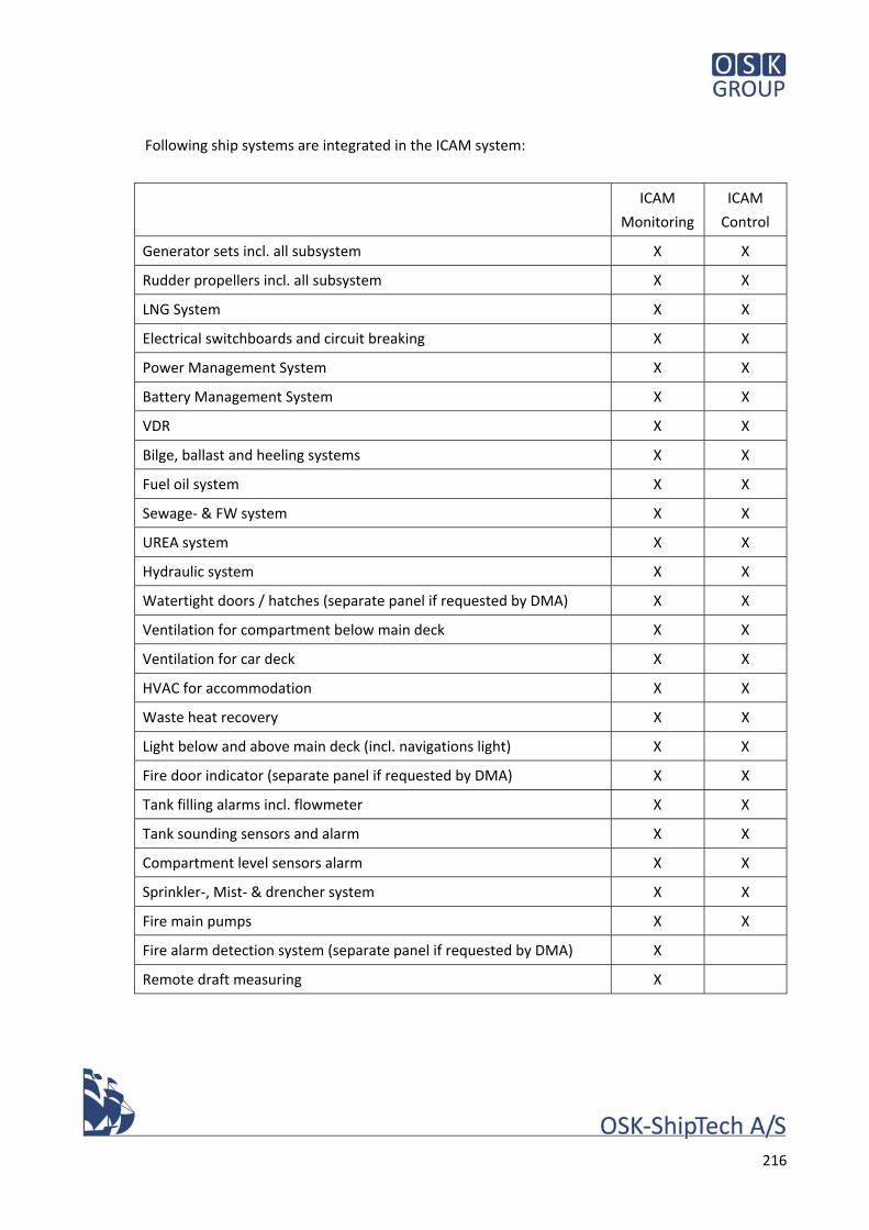
216
Following ship systems are integrated in the ICAM system:
ICAM
Monitoring
ICAM
Control
Generator sets incl. all subsystem X X
Rudder propellers incl. all subsystem X X
LNG System X X
Electrical switchboards and circuit breaking X X
Power Management System X X
Battery Management System X X
VDR X X
Bilge, ballast and heeling systems X X
Fuel oil system X X
Sewage‐ & FW system X X
UREA system X X
Hydraulic system X X
Watertight doors / hatches (separate panel if requested by DMA) X X
Ventilation for compartment below main deck X X
Ventilation for car deck X X
HVAC for accommodation X X
Waste heat recovery X X
Light below and above main deck (incl. navigations light) X X
Fire door indicator (separate panel if requested by DMA) X X
Tank filling alarms incl. flowmeter X X
Tank sounding sensors and alarm X X
Compartment level sensors alarm X X
Sprinkler‐, Mist‐ & drencher system X X
Fire main pumps X X
Fire alarm detection system (separate panel if requested by DMA) X
Remote draft measuring X
217
All possible alarms, levels, indication, controls etc. (both individual and group) alarms from
engines and other systems to be connected to the ICAM. Systems may only be separated from the
ICAM into minor separate panel according to agreement with the Owner, or if required by
regulations.
Power management system (PMS) shall be included in ICAM. PMS shall be unlimited in the sense
that it must be able to accommodate extensions to a 100% battery powered vessel.
Battery management system shall be included in ICAM. Battery management system shall be
unlimited in the sense that it must be able to accommodate extensions to a 100% battery
powered vessel.
The ICAM system to be computer based with a user interface consisting of two (2) Graphic
Operator Station (GOS) installed on the bridge at the Chief Engineers station, one (1) GOS
installed in the engine control room, one (1) GOS installed in engine room aft, one (1) GOS
installed in engine room fwd.
All five (5) GOS to be fully operational independent from each other and to be fully editable by
the crew for level adjustment etc.
Duty alarm panels are to be fitted in mess room and six (1) crew relaxing cabins.
All engine alarms are also sent to the chief engineers UHF.
All essential parts of the system such as distributed control stations, operators workstations and
accommodation panels, shall be connected to two (2) fully redundant and independent network
of high capacity and suitable for marine purpose.
A possibility to connect a shore‐based work and monitoring station via satellite shall be included.
SMS warning system:
The ICAM system shall further include a SMS warning system, when the Vessel is laid up for the
night.
The SMS warning system shall forward a text based warning to the officer on duty in case of 1 of
the following events:
Burglary alarm
Fire alarm
Loss of heating power
Bilge‐ or flooding alarm
Blackout
218
The SMS warning system to be with automatic dialling to up to five (5) pre‐selected shore
telephone numbers in the event of alarms.
In general the ICAM system shall be designed with a spare capacity of at least 40% with respect to
both memory and CPU load for each intelligent module.
The system shall have 20% spare capacity for each type of I/O etc.
0922 Miscellaneous Alarm Systems
LNG System alarms according to Class requirement and IMO 1455 analyse.
Engine Room Alarm light‐ and sound panel according to normal standard to be installed in
compliance with applicable rules and regulations.
0923 List of Alarms
Un‐erasable alarm list to be saved in the ICAM system. Alarm to include time, incident, back to
normal time.
0925 Burglary alarm System
One (1) burglary alarm system to be fitted on all external doors.
The system shall be connected to the ICAM system as per 0921.
0926 Dock alarm for Orskov Shipyard
A pushbutton for activating the dock‐evacuation‐alarm, at the Orskov Shipyard in Frederikshavn,
shall be fitted on the brigde.
0950 Automation of Ancillary Systems
0951 Sequential Restart of ancillary machinery
The following machinery to be arranged for automatic sequential restart after black out:
Gen. Set.
Starting air compressors
Engine room supply ventilation fan
LNG equipment
219
HVAC, ventilation and heating system
Other small essential motor and loads
For stand by pumps, the exact unit running before the blackout shall be restarted.
Power for lighting, navigation equipment, radio equipment, alarmsystem, firedampers and
various control equipment has to be reverted instantaneously. UPS according to 0818
0953 Automatic start of standby pumps
Automatic start of stand‐by pumps according to class requirements.
0954 Fuel Oil Bunker and Transfer System (aut)
MGO settling transfer pumps must be able to run in manual as well as automatic mode. When
running in automatic, start and stop must be controlled by float switches in settling tanks
mentioned in 0727.
0960 Automation of Auxiliary Systems
0961 Remote Controlled Valves
Remote control to be arranged for the valves, including ship side valves as specified below for the
following piping systems in the engine room:
Ballast, trim and heeling system
Bilge system
MDO transfer system
LNG System
FW bunker
Sewage system
Fire system
Drencher system
Overboard valves
See also 0718
The valves shall be controlled from the ICAMS.
The remote operated actuators to be of an integrated electro‐hydraulic type directly build on
each valve. The actuator consists of electrically driven hydraulic pump, several valve functions and
pos. indication. The unit is directly electric powered and controlled by a bus system connected
220
and controlled from ICAMS.
Hydraulic pipes to be arranged in “Ring” or “Star” formation according to agreement with the
Owner.
0970 Safety System, Requirements
0972 Fire Doors (indication & control)
Fire Doors, Wheel House Panel
One panel for remote release of fire doors to be provided in the Wheel House:
indication of each fire door (open/closed) shown with red/green light on mimic diagram in ICAM (or separate panel if required by DMA)
remote release of any magnetic holdbacks throughout the vessel.
Acoustic alarm with volume control
0973 Watertight Doors and Bow visor etc.
Watertight Doors:
One (1) panel for indication and remote operation of watertight doors to be provided in wheel
house (or integrated in the ICAM system if possible).
Indication of each door (open/closed/secured) shown with red/green light on mimic diagram
Acoustic alarm with volume control
Bow Visor etc. Panel:
Two (2) panels for indication and remote operation of visors, ramps, shell doors etc. to be
provided in the wheel house, – one panel near each conning position.
Indication of hatch/visor (open/closed/secured) shown with red/green light on mimic diagram
Acoustic alarm with volume control
0974 Fire dampers
Fire‐ and smoke dampers in all mechanically ventilated compartments shall be remote controlled
from fire alarm system on the ICAM.
221
Dampers shall be with motor driven re‐opening. In event of power failure, dampers shall
automatically revert to previous open/closed state after restoration of power.
0975 Fire Alarm System
Fire detection and alarm system in compliance with the requirements of Class and DMA to be
installed, with smoke/heat detectors throughout the vessel.
Flame detectors and oily fog detectors to be fitted in both engine rooms.
Sensors on car deck to be infrared type.
Alarm panel with mimic diagram to be integrated in the ICAM system in the Wheel House,
showing group alarms with possibility for identifying individual detectors.
Sufficient number of fire bells to achieve required sound level in all passenger and service spaces,
accommodation and engine rooms.
Press buttons for general alarm, boat alarm, abandon ship alarm etc. in Wheel House.
Separate and combined activation of alarms for crew, service and passenger spaces.
0976 Gas Alarm System
One (1) gas alarm plant for continuous detection of gas leaks shall be installed, meeting Class and
DMA requirements.
Gas alarm limits (low and high) shall be defined for each detector’s location. Gas alarm limits shall
be adjustable.
0980 Miscellaneous Automation
Motion sensors on hoistable decks.
Ten (10) ultrasonic motion sensors must be placed at the hoistable deck. One (1) sensor over each
moveable section (six (6) in total), and one (1) sensor below each flap (four (4) in total). Must be
possible to disconnect (make powerless) when transporting dangerous goods.
If one of these sensors are activated, while the section in question is operated, an alarm (visual
and audio) must be activated at the local control station.
222
If it should be possible to operate the suspendable deck sections, while a motion sensor is
activated, is up to Owners approval. In case of sensor failure, it must be possible to manually
overrule failsafe operations.
0983 Remote Sounding System
Remote sounding sensors to be installed for the following tanks:
Ballast, trim and heeling tanks
MDO tanks
LNG tanks (Option 1 only)
Sewage Water Tank (ullage, ultrasonic or similar type)
FW tanks
Waste oil, drain oil and oily water tanks
Soundings and compensated tank contents to be displayed on the ICAMS Graphic Operator
Stations by means of both bar graphs and digital indication. Colour of bar graphs to change in
alarm and failure situations.
All tank sensors for remote sounding to be flange mounted on the tank from outside, making
dismounting possible without interring the tank.
0985 Draft Measuring
Remote draught measuring probes, connected to ICAM system, to be fitted fore‐ and aft, port and
starboard (four probes total)
The probes shall be retractable, with sea valve, enabling them to be withdrawn/replaced afloat.
223
100 Cargo Handling
170580.0131.01
Date 12.04.18
Sign JFH
224
100 Cargo Handling
1000 Bow Visors, Car Stops and Hoistable Car Decks
1001 General
The vessel is to be equipped with a hydraulically operated system of bow‐ and stern visor and
hoistable car decks. All clamping‐, opening‐, closing‐ and folding sequences shall be automatic and
remote controlled, so that no manual clamping, operation of car stops, or rails etc. is necessary.
Local control of visor and car stops, including start/stop of pumps from relevant end of car deck.
Bow visors fore and aft shall also be remote‐controlled from Wheel House.
Ground cable to be fitted between the hull and the fore/aft bow visor.
All movable hinge etc. to be with central lubrication.
Hoistable decks shall be operated from the relevant end of the operated deck Positions (four
total) to give operator good view over the work area.
Operating times for system:
Opening /closing of bow visor max 50 sec
Clamping of visor approx. 5 sec
Opening/closing of car stop max 6 sec
Lowering/hoisting of hoistable deck for PCU‐cargo operation, with car load: max 15 sec, with
soft stop
Hoisting or lowering of complete hoistable deck in one side (three sections) max. 30 sec.
These high speeds shall be achieved safely by dividing motions into phases with out pauses:
Accelleration phase
Steady, high speed phase
Deceleration phase
Slow phase when coming into contact
Above times shall be achieved at 12oC air temperature, and shall enable a turnaround harbour
time with full PCU load of 15 minutes.
The cargo handling and access equipment shall operate at angles of list and trim, which may be
expected during normal loading and discharging, without use of ballast‐ or heeling pumps.
225
The vessel shall be built with recesses for landing and connecting of shore ramp by means of king
pins. Strength of king pin and arrangement shall be sufficient for taking longitudinal forces during
loading and discharging, and be determined according to BS 6349‐8:2007 including Danish
Supplement.
Fully accessibility to the electrical control panel for the hydraulic system to be granted, giving the
Crew the possibility to make adjustment on all parameter.
1013‐1 Bow/Stern Visor
Bow visor to be provided with 2 hinges on forecastle/mooring deck, 2 hydraulic lifting cylinders in
bow visor space PS and SB, "icebreaker" cylinders and hydraulic securing in open position.
Hydraulic clamping system with indication etc. according to rules.
Bow visors shall be operable from local panel at end of car deck, including start/stop of pumps.
Bow visors shall further be operable from wheelhouse, including start/stop of pumps.
All shafts, pins and locking bolts shall be AISI 329.
Bearings and bushes shall be bronze, grease lubricated through central greasing system.
Bow visor structure to be kept as light as possible while fulfilling class requirements for bow
impact and ensuring sufficient rigidity by means of internal diagonal truss pipes.
Bow visor shall be weathertight towards ships sides and recess, by means of rubber gasket against
stainless steel compression surface.
Free height below open visor: 6.0 m
1013‐2 Car Stops
At the end of vehicle deck, approx. fr #+/‐78, a car stop flap shall be installed, hinged at top of
recess for shore ramp
The car stop shall in upright position act as bulwark towards the recess, in lowered position the
stop shall rest on the shore ramp and act as transition piece when driving from deck onto shore
ramp.
In upright position, the car stop shall be locked by means of hydraulic bolts; in lowered position
the hydraulics shall be in floating position.
226
Operation of car stop from relevant end of car deck, including start/stop of pumps. No remote
control.
The car stop flap shall consist of a heavy steel plate without stiffening, design loads as for car
deck. The car stop shall be divided into two linked panels, giving flexibility towards shore when
the vessel has a list.
Transition towards deck and shore shall be smooth, so that cars are not required to lower speed
when entering or leaving the car deck. No significant noise or bangs shall emit from cars passing
the car stop.
Anti‐skid shall be by means of paint with anti‐slint, no welded herringbone pattern.
1015 Hoistable Car Deck
The vessel shall be equipped with hoistable car deck port and starboard, 2 x 73,2 m
Each of the decks shall consist of three sections. The ends of the end sections shall be able to be
lowered down to main deck to form ramps, and be equipped with folding car stop, which acts as
transition piece mitigating the knuckle. The end sections shall be operated with a full load of PCU
incl. passengers inside.
The end sections shall further be capable of being stowed separately, while the remaining two
sections are in use.
The middle section shall be equipped with a car stop closing the section to bulwark height when
the end section is stowed separately, and forming transition to end section during ordinary
loading/discharging/transit.
All three sections shall be stowed by hoisting up below deck 4 level.
Local control of visor and car stops, including start/stop of pumps from relevant end of car deck.
Each of the four control stations shall control ramping operation of PS and SB end section at
relevant end and separate stowing of PS and SB end sections below deck 4, and stowing of all
sections below deck 4 simultaneously. It shall not be possible to ramp up/down, or stow
separately the end sections of opposite end, for reason of safety.
When operating the hoistable car deck, it shall be possible to go from ramped position to stowed
position below deck 4, and vice versa, without going through the locking phase at deck 3.
Both hoistable deck to be operated simultaneously.
Indicator for sensor failure next to both conning positions.
227
Maximum inclination of ramps: 7o. Transition between middle section and lowered end sections
shall be chamfered in order to reduce knuckle. No significant noise or bangs shall be caused by
cars passing the joints.
At all free edges not covered by casing sides or car stop, rails shall be fitted.
In way of middle section and inner ends of end sections, the rail may be fixed between centre
pillars. Where end sections ramp down to less than 3,0m above deck, the rail shall move
automatically along with the end ramp in question.
Car stop shall fold automatically in loading and transit mode, and when hoisting up the deck to
stowed position.
The deck shall be hoisted by means of jigger winches and be supported by preventers, locking
bolts and guides in casing/vessel sides.
All guides, wires, sheaves, preventers, cables and hoses shall be recessed into casing sides or be
installed between centreline pillars.
The deck and its equipment shall be of lightweight construction making use of high tensile steel
and lightweight material.
Doors entering the deck or being below moving parts of it shall be interlocked with the operating
system.
Hoisting, lowering and clamping operations shall be automatic, programmed in sequences.
Operation of car decks shall require the button to be pressed by operator for the entire time of
operation.
Locking and disengaging of locks shall be indicated on operators panel.
DMA rules for hoistable car decks and their safety devices to be observed.
Visual and audible alarms at each hoistable deck section.
1018 Hydraulic System for Visor, car stops, hoistable deck, and winches
Two independent hydraulic units, one fore, one aft, to be installed for operation of bow visor,
forward and aft ramps, mooring‐ and anchor winches.
The hydraulic units are to be placed in the engine rooms, each with 2 pumps of capacity to fulfil
operating times above with both pumps running. The hydraulic oil tank connected to the power
pack to be fitted with heating coils (from heat recovery water system).
228
Hydraulic pumps to be variable wing pumps and the system to be fitted with hose burst valves.
Cross connection between fore and aft unit, separation valves for isolating the units and section
valves for main groups of equipment, enabling hoistable car decks, visor/car stop, or winches to
be serviced separately.
Working pressure max. 210 bar.
In the event of failure of one pump, the other shall be capable of operating the system at about
half speed.
Unit to be equipped with oil cooler/air blower, alarm for low oil level/high temperature, stop of
motors at low oil level, pressure relief at motor start.
Hydraulic oil filter of water‐separating offline type with heat to be provided.
All pipes to be stainless steel connected with stainless steel flared fittings. Approved flexible hoses
for connection to pumps and cylinders.
Hydraulic cylinder in exposed positions to be with stainless steel AISI 329, chromium plated ram.
Pins, bolts, nuts etc. to be Stainless steel 1.4404 or better.
Hose burst valves to be fitted at hydraulic rams.
The hydraulic system shall be designed and installed, aiming at low noise emission. Vibrations and
pressure shocks to be avoided. Oil velocity in pipes not to exceed 4 m/s. Pipe hangers and
bulkhead intersections to be sound resilient.
Noise level on car deck with hydraulic system in operation shall not exceed 80 dB(A) (excluding
noise from ramps etc. reaching end stop position)
Emergency operation of the system shall be possible by manual operation of valves and portable
HPU. Emergency operating valves shall be situated centrally in an accessible and safe position
near the equipment.
Diagnostics of system failure, localization of failing sensors etc. shall be possible from car deck.
Emergency operation valves to be located near the normal operation areas – according to Owners
requirements.
1031 Platform lift for engine stores
One (1) hydraulic 1000 SWL platform lift to be provided in an integrated trunk in SB side, stopping
levels are floor above tank top and main deck.
229
No doors or hatched are provided as an integrated part of the platform lift.
One (1) water tight door is provided in the bulkhead towards car deck – see 0205
The lift shall not be approved for passenger or crew transport. It shall be connected to the ICAM
system to ensure use only during harbour stay.
It must be possible easily to place and remove a pallet (800x1200) with a pallet lifter on both
deck.
Lower level of the platform lift to be in same level as the floor in the workshop. Upper level of the
platform lift to be in same level as the car deck.
One complete hydraulic cylinder for bow visor and one complete hydraulic cylinder for car stop operation to be delivered as spares.
END OF DOCUMENT