FRACTURE TOUGHNESS OF ICE: A PRELIMINARY … · A PRELIMINARY ACCOUNT OF SOME NEW EXPERIMENTS B)...
10
J ournal of Glaciology, Vol. 2 1, No. 85, 1978 FRACTURE TOUGHNESS OF ICE: A PRELI M INARY ACC OUNT OF SOME NEW EXPERIMENTS B)I D.]. GOODMAN and D. TABOR (Ph ys i cs and Chemistry of Solids Group , Cavendish L aboratory, Madingley Road, Ca mbrid ge C B3 oRE, England ) ABS TRACT. Th is pap er describes the first results from an expe riment to meas ur e th e fr actur e toughness of ice. Two expe riment a l tech niq ues h ave be en use d; fr act ur e of pre-n otched rectangu lar speci mens in t hr ee- and fo ur-po in t be nding, an d from th e obser va ti on of th e cracks whi ch form und erneath an ind e nt er for ced into the ice s urf ace. I n the lat ter t est the ind enter beh aves like a wedge. We have observed th at for ind e nt ers with la rge int er ior ang les th e pl ast ic zone beneat h the ind ent er may itse lf beha ve like a wedge . Data obtain ed over a range of temp er atu res has been comp ared w ith the little other data avai la ble. We find a decrease of fr act ur e toughness as the te mperature is l owered, which is the reverse of that obse r ved by H. VI/ . Liu and L. W . L oop. R ESUME. Resista nce cllafractllre de la glace : aperfu /Heli lll inaire de qllelqlles nOll velies experiences . Nous d ec ri vo ns dan s ce trava ill es prem iers res ultats iss us d 'ex pe ri ences perm e tt ant l' etude de la resistance a la fra c tur e de la glace . Nous avons utili se deux techniqu es expe rimentales: d' un e part la fra ct ur e d'eprouveltes e nt a ill ees, a sec tion rectangula ir e et soumise a la Aexion a tr ois et qu a tr e poin ts. D 'a utr e part, I'o bservation des fi ss ur es se formant en d ess ous d' un e pointe d' ind e ntati on dont on provoqu e l'e nf orce ment a la surface de la g l ace. Dan s ce dernier cas, la point e d'inden ta ti o n se compo rt e com me un co in ; en o utr e, nous avons observe qu e, po ur d es angles d'ouvertu re de I'ext rem it e de la pointe imp ortants , la zone plast iqu e formee en dessous de la point e d'ind ent ation, peut e ll e-meme j ouer le role de coin. Des donn ees obten u es dan s une large gamme de te mper atur e ont e te co mparees avec les quelques un es dont nous pou vions di spose r. Nous trouvons un e d ecro issance de la resista nce a la frac tur e qu a nd la temp era tur e d ec rois ce qui est l'inverse d es obser vat i ons d e H . W. Liu et L. VV. Loop. Z USAMMENFASSUNG. Bruch Z iihigke it vo n Ei s: e in vo rldllfiger B eric;'t llber einige nelle Versllche. Diese Arb eit beschr eibt die ersten Ergebn isse ein es Versuch es w r M ess ung der Bru chzahigkeit vo n Eis. Es wurden zwe i Vers uchsverfa hr en a ngewe nd et: Bruch vo n vo rgekerbten r ec ht ec kigen Proben d ur ch Dre i- und Vier-P un kt- Bi eg un g und aus d er Beo bac htung vo n Sprungen , di e unte rh a lb eines in d ie Ei sober A ache gedr uc kt en P rufkiirpers entste he n. Bei c1 em zweiten Ve rf a hr en verh alt sich der Eind ringprufkii rper wie ein Keil. Wir beo bacht eten, dass bei grossem Sp itzcnw ink el d es Prufk ii rp ers di e p las ti sche Zo ne un ter halb d es Prufk ii rp ers sich selbst wi e ein K eil ve rh alten ka nn . Di e ub er einen grosse n Temperaturbereich erha ltenen W e rte wurden mit den we ni gen a ncl eren ve rfu gbaren Werten verg li chen. Wir finden ein e Abnahme de l' Bru c h- zah igkeit mit ab ne hmende r Temperat ur ; di es ist e ntgegengese tzt zu der Beobac ht un g vo n H. W. Liu und L. W. L oop. I. I NTRODUCTION The simplest typ e of fr act ur e m echan isms occurs in " id ea ll y brittle" so lids. In these materials there is a criti ca l str ess at whi ch a crack b ecomes un stable a nd propagates. Griffith (1920) showed by a simpl e energy arg um ent that the cr ack propagat ion occurs wh en the rat e of rel ease of elastic stra in energy is equ al to (or gr eater than) the in creme nt al in crease in surf ace energy associat ed with the form at i on of new surf ace at the cr ac k tip. With most real m ate rial s which show some ductility includin g metals, polymers, a nd ice, the fracture pro cess involves not only the true su rf ace ener gy of the solid but also creep and deforma ti on pr ocesses at the crack tip. The energy involved in this process m ay easily swamp th e surface ener gy term itself. Failure m ay n ot be prim ar ily du e to th e propagation of a crac k but to the fl ow a nd ductil e separa tion of the specimen int o two pa rt s. T he tr ansition from ductile failure to failure by crack propagation is contro ll ed by the time co n stant of stress rel axa tion at the c rack tip. At high stresses a nd low temperatures or high st rain-r ates, the time co nstant is too lo ng to preve nt cracks reaching a criti ca l size beyond whi ch th ey are unstab le; and propagate through the lattice. In the expe rime nt s to measure the "strengt h" of polycrystalline i ce by Rawkes a nd Melior (1972) a nd Wu an d others (1976) in uni axial comp ression and tension, a tra nsition from du ct ile to brittle beh av io ur was obser ved at a stra in - rat e of abo ut 10 - 5 to 10- 3 S- I (the temper at ur e was between - 1 a nd - lo oe in Wu and others' experiment, and - 7°C in Hawk es a nd Melior 's exp er iment ). 22
-
Upload
nguyendang -
Category
Documents
-
view
214 -
download
1
Transcript of FRACTURE TOUGHNESS OF ICE: A PRELIMINARY … · A PRELIMINARY ACCOUNT OF SOME NEW EXPERIMENTS B)...

J ournal of Glaciology, Vol. 2 1, No. 85, 1978
FRACTURE TOUGHNESS OF ICE: A PRELI MINARY ACC OUNT OF SOME NEW EXPERIMENTS
B)I D.]. GOODMAN and D. TABOR
(Ph ysics and Chemistry of Solids Group, Cavendish L aboratory, Madingley Road, Cambridge C B3 oRE, England)
ABSTRACT. Th is paper d escribes the first results from a n experiment to measure the fracture toughness o f ice. Two experimenta l tech niq ues h ave been used; fracture of pre-notched rectangular specimens in three- and fo ur-poin t b ending, and from the observa tion of the c racks which form undernea th an inde nter forced into the ice surface. I n the latter test the indenter beh aves like a wedge. W e have observed that for indenters with la rge inter ior angles the plastic zone beneath th e indenter may itself behave like a wedge. Data obtained over a range of temperatu res has been compa red with the little oth er data avai la ble. We find a d ecrease of fracture to ughness as the temperature is lowered , which is the reverse of that observed by H. VI/. Liu and L. W . Loop.
R ESUME. Resistance cllafractllre de la glace : aperfu /Helilllinaire de qllelqlles nOllvelies experiences. Nous decri vons dans ce travailles prem iers resultats issus d 'ex peri ences perme ttant l'e tude de la res istance a la fra cture de la g lace. Nous avons utili se d eux techniques experimentales: d ' une part la fracture d'eprouveltes enta illees, a sec tion rectangulaire e t soum ise a la Aex ion a trois et qua tre poin ts. D 'autre part, I'observa tion des fi ssures se formant en dessous d ' un e poin te d 'indentation dont on provoque l'enforcement a la surface de la g lace. Dans ce dernier cas, la pointe d ' inden ta tio n se comporte comm e un coin ; en outre, nous avons observe que, pour d es angles d'ouvertu re de I'extrem ite d e la pointe importants, la zone plastique formee en dessous de la pointe d'indenta tion , peut e lle-meme j ouer le role de coin . D es donnees obtenu es dans une la rge gamme d e temperature ont e te compa rees avec les quelques unes dont no us pouvions disposer. Nous trouvons une decroissance de la resistance a la fracture qua nd la tempera ture d ecrois ce qui es t l' inverse des observations d e H . W. Liu et L. VV. Loop.
Z USAMMENFASSUNG. Bruch Ziihigkeit von Eis : ein vorldllfiger Beric;'t llber einige nelle Versllche. Diese Arbei t beschreibt die ersten Ergebn isse eines V ersuches w r M essung d er Bruchzahigkeit von E is. Es wurden zwei Versuchsverfahren a ngewendet: Bruch von vorgekerbten rechteckigen Proben d urch Drei- und Vier-Pu n ktBiegung und aus d er Beobachtung von Sprungen, die unte rha lb eines in d ie EisoberAache gedru ckten P rufkiirpers entsteh en. Bei c1 em zweiten V erfa hren verhalt sich der Eindringprufkii rper wie ein K eil. Wir beobachteten, dass bei grossem Spitzcnwinkel des Prufkiirpers di e p las tische Zone un terhalb des Prufkiirpers sich selbst wie ein K eil verhalten ka nn . Die uber einen grossen Temperaturbereich erha ltenen W e rte wurden mit den wenigen a ncleren verfugbaren Werten ve rg li ch en. Wir find en eine Abnahme del' Bruchzahig keit mit abnehmender Temperatur ; dies ist entgegengese tzt zu der Beobach tung von H. W. Liu und L. W. Loop.
I . I NTRODUCTION
The simplest type of fracture m echanisms occurs in " ideally brittle" solids. In th ese materials there is a critical stress a t which a crack becomes unstable and propagates. Griffith (1920) showed by a simple energy argument that the crack propagation occurs when the rate of release of elastic strain energy is equal to (or greater than) the incremental increase in surface energy associated with the form ation of new surface a t the crack tip. With most real materials which show some ductility including metals, p olymers, and ice, the fracture process involves not only the true surface energy of the solid but also creep and d eformation processes at the crack tip. The energy involved in this process may easily swamp the surface energy term itself. Failure m ay not be primarily due to the propagation of a crack but to the flow and ductil e separa tion of the specimen into two parts. T he transition from ductile failure to failure by crack propagation is controlled by the time constant of stress r elaxation at the crack tip. At high stresses and low temperatures or high strain-ra tes, the time constant is too long to prevent cracks reaching a critical size beyond which they are unstable; and propagate through the la ttice. In the experiments to measure the "strength" of polycrystalline ice by Rawkes a nd Melior ( 1972) and Wu and others (1976) in uniaxial compression and tension, a transition from ductile to brittle behaviour was observed at a strain-rate of about 10- 5 to 10- 3 S- I (the tem perature was between - 1 and - looe in Wu and others' experiment, and - 7°C in Hawkes and Melior's experiment).
22

J OURNA L OF GL AC r O L OG Y
H awkes and Mellor also observed differen t strengths for tensile a nd compressive failure in the brittle region . T his is to be expected becau se in a tensile test a single crack can lead to the eventual fa ilure (unless failure is by void grow th when many voids j oin up). By contrast in a compression test many cracks nucleate, change the local stress field , and link up in the final catastrophic fai lure. To ob tain a better understa nding of the fracture process i t is clearly desirable to work with a system involving single crack propagation .
A number of workers have studied crack initiation in ice a nd have proposed various theories based on the pile-up of dislocations (e.g . Gold , 1967) . On the other hand only two papers have discussed the propagation in ice of cracks of known geometry. G old (1963) formed thermal cracks by bringing together two blocks of ice a t different temperatures. He measured the dep th to which cracks propagated , a nd the time a fter the blocks were brough t together for the cracks to run. H e then ana lysed the crack propagation process in terms of the diffusion of a thermal wave in the block, and the stresses produced by the temperature. H. W. Liu a nd L. W. Loop (personal communication of unpublished data) have used a compact tensile specimen (CTS) . H ere a sing le cracked block is pulled apa r t by fix tures through holes a bove and below the crack, a common technique for fracture studies. T hey also used a wedge-opening technique (see Fig. 1) .
CTS WEDGE
Fig. I. The lest specimens used by Liu and Loop.
M ost of the previous inves tigations of crack propagation in ice have involved rela tively la rge specimens, e.g. three-point and four-point b ending tests, compact tensile specimens, etc. The present paper describes some preliminar y experiments in w hich a crack is formed and propagated under a conical or pyramidal inden ter pressed into the ice. T his h as the advantage that m any measuremen ts can be carried ou t on a single specimen. A few experiments have also been carried ou t in three- and four-point bending.
2 . CONCEP T OF FRACT UR E TOUGHNE S
Griffith's energy argument for the cri tical stress Gc to make a crack of length 2C propagate in an infinite solid when the stress is applied at r igh t angles to the crack is
_ (2Er)! Gc - ,
7TC (1)
where r is the surface energy, a nd E the Young's modulus if the crack is in pla ne stress (in pla ne strain E is replaced by E /( 1 -vz)) . I f plastic deformation occurs at the crack tip, Equation (1) is a lower bound to the critical stress .
Comprehensive reviews of fracture toughness can be found in L awn and Wilsh aw (1975), Knott (1973), K enny and Campbell (1967), Liebowitz (1969-72 ), and T urner (1975) . T wo useful para meters have been introduced : the stress intensity factor K which is the ratio of

F R ACTU RE TOUGHNESS OF I CE
true stress a t the crack tip to the average applied stress, a nd C which is the ra te at which energy is released per unit length of crack advance. The particular stress intensity factor of interest to us is that for a crack being pulled apart by a stress norma l to the crack plane (mode I) , and this is d esignated K 1 ; its limi ting value at which fracture occurs is K1C ' The stress could be applied so that the crack faces move over each other perpendicular to the crack front (mode 2) or parallel to the crack front (mode 3) . G is genera lly referred to as the frac ture to ughness of a solid. In the perfectly brittle case G can be identified with 2f but if plastic work is performed at the crack tip C is the sum of the plastic work and the surface energy. The difference G- 2f is then a m easure of the p lastic work involved in crack propagation . For a metal such as steel 2f is about 10 J m- 2 while G is of order 40000 J m- 2 • The quantities K and G ar e r ela ted by the expressions:
in pla ne stress
(n)
a nd in plane strain
These parameters can be applied to situations where plastic flow occurs provided the plastic zone is small compared with the crack length a nd hence with the elastic hinterla nd within which the crack propagates . In the Irwin- Orowa n m odel, the plastic zone at the crack tip is assumed to be cylindrical with a radius Tp given by
rp = ~ 2~ (~:) , (3)
where cry is the ideal plastic yield stress . With a materia l close to its mel ting temperature the yield stress cry will not be a constant but will depend on the stra in-rate . For this reason in a ll fracture studies it is n ecessary to estimate the ex tent which significant plas tic flow occurs (i .e. the size of T p corn pared wi th 2C) .
In the present series of experiments, the strain-rates were estimated to range from 10- 4 to 10- 2 S - I. Using earlier m easurements of yield stress as a function of stra in-ra te at vario us temperatures, it was possible to estima te cry and hence the order of magnitude of rp. T his proved to be about 0.04 mm which is much smaller than the length of the cracks studied. Consequently it is reasona bly valid to use the elastic equa tions (Equation (2)) to define the stress field close to the crack tip. Clearly this assumption breaks down a t very low stra in-rates.
To obtain reproducible values of K 1c two further conditions must be m et. First, the specimen width must be la rge enough so that the major pa rt of the crack is in plane-strain conditions (this is usuall y met if the width is greater than a bo ut 50rp (Knott, 1973)) . Second ly, the crack tip radius throug hout the propagation must be so small that the perturbation of the stress fi eld due to the crack can be represented by a singula rity at the crack tip . In metals the value of K 1c has been found to fall to a limiting value as the crack tip ra dius is reduced , a nd it is usua l, in a fracture test, to introduce a small sharp c rack by fatigue. It is not possible to introduce a faticrue crack into the ice specimens with the present set up, but in the three- a nd four-point bending exp eriment a very sha rp crack was formed by pushing a razor blade into a slot formed by melting. The tests were carried out in a ir a nd it is importa nt to realize that environment can have a la rge influence on crack growth.
3. EXPERIMENTS
3. I. Specimen preparation Specimens were grown in a water-fi ll ed tank inside a d eep freeze (air temperature - 10
0 e). The water used was once-distilled. The r a te of growth could be varied by cha nging the se ttini-{

JO U RNAL OF GLACIOLOGY
on a water-temperature thermostat connected to a heater. Bubble-free specimens roughly 130 mm X 30 mm X 20 mm could be obtained after about a night and a day. The specimens were brought to the desired shape by melting them on an aluminium block at room temperature. They were stored at - IOoe, in air, in the deep freeze. They were usually used within two days of manufacture; many were reshaped just before a test. Observations of the grain size (which varied from I mm to almost single crystals) were made with a universal stage on an optical microscope. Specimen dimensions were m easured with vernier calipers to an accuracy ofo.1 mm.
o
,-----, ,'-----, .--J
.-
P I NTERCHANGEABLE l HEADS
n I CE SPECIMEN
Inl ~ 0 PT/CAL SYSTEM
LOAD CELL
FRACTURE TEST RIG SECTION AA
Fig. 2. The fracture test rig set up for indentation experiments. The same loading arrangement was used in the three- and four-point bending tests.
3.2. Loading arrangement
The fracture toughness of ice is very low; a bar of cross-section 20 mm X 20 mm can be broken with one's fingers. Therefore it is possible to use a small, inexpensive rig completely contained within a small deep freeze to measure the fracture toughness. The arrangement is shown in Figure 2.
Oil from a hand pump was driven into the ram to force the indenter into the ice block. The ram h eads can be interchanged to give various loading a rrangements (three- and fourpoint bending, Vickers Diamond Pyramid, or other shaped indenters). The magnitude of the force is measured with a load cell beneath the ice block.
3.3. Three- and four-point bending test
Specimens, from the tank, were melted down to a bar shape, and then midway along one side a slot was melted with a thin copper plate to about half the thickness of the bar. At the end of the slot a very sharp crack was formed by pushing a razor blade into the ice. The ice block was put into the small deep-freeze unit containing the loading rig and allowed to equilibrate. The loading arrangement is shown in Figure 3.

F R ACT U R E TO U G H NE SS O F ICE
LOAD FROM HYDRA ULIC
RAM
I
I C E
CRACK
~ r /r---'~-'-r------'---'---'---''----'------'--'-----r---'-----''----r'~f--.'- .
. L _ ~
655
F ig. 3. T he loading arrangement jor the Jour-point bend tests. I n the tliree-/Joint bend test a s·ingle loading cy linder (giving line conlnel ) is aJJ/Jlied 0 11 the upper sw:face immediately above the crack .
Some three-point bending experiments (this is the B.S. I. standard) were carried out at - 14 QC for a loading time of less than 10 s. Pla ns were also m ade to undertake som e fourpoint bending tes ts since this si tua tion provides a constant bending moment in the central section of the bar between the two upper loading cylinders: consequently, in contras t to the three-point tes t, the loading ram does not have to be located exactly above the crack.
3+ j\;fedian crack formation beneath an indenter
When a dia mond Vickers indenter (Tabor , 19 70) is forced into the surface of an ice block to p roduce the usual ha rdness inden ta tion, median cracks form with their planes perpendicula r to the surface (see F ig. 4). T hese a re a pparently formed by the wedging action of the inden ter. When the load is removed the sub-surface tension componen t about the deformed zone below the indenta tion nuclea tes a nd propagates another set of latera lly extending cracks. The depth of the median crack is a measure of the fracture toughness, and can be deduced from the trace o n the surface assuming that the crack is semicircula r in shape. If Ij; is the semi-a ngle of the V ickers pyramid, the fracture toughness is given (Swa in a nd Lawn, 1976) by
./
I~-
K 1C = p
( TTC ) i tan Ij; ,
Fig. 4. The geometry oj the crnck j ormed beneath a Vickers indellt .. · when Equation (4) ap/Jlies. Frequently the crack ran to the intersection between two jaces oj the indenter, and was not always in a direction/Jerpendicular to the edge oj the indentation.

JOURNAL OF GLACIOLOGY
where c is the crack length, and P is the load. If K is constant then P should be proportiona l to cI . Thus a plot of P versus c~ may b e used to deduce K 1C (see Fig. 5) .
The experiments were carried out by attaching a diamond Vickers indenter or a conical indenter to the ram and forming median cracks for different loads. These ranged in len g th from I to 10 mm and could be measured with an accuracy of about 2 % . They were generally formed within a single grain. Often three cracks were formed with trigonal symmetry, a nd changed their direction at a grain boundary. This su ggests, as others have observed (Gold,
CRACK RADI US
m 312
o 0 0
VICKER S DIAMOND IND ENTER
136 0
~ ~~~ ___________ 3J?_0 _____________ 40LIO ____ _
CRACK RADIUS
m 312
o
~o 100
LOAD
200
(a)
60 0 CONE
o
300 400
(b)
500 N
T =-20 0 -
500 N
Fig. 5. M edian crackJormatioll ill ice. Plot of normal load P (in newtolls ) against (crack length)'!. (in mi ) . The slope provides a meaSllre of K 1 C'
(a) Vickers /J)'ramidal indenler with semi-angle if; = 68°. (b) Conical illdellter with semi-angle if; = 30°.
FRACT R E TOUGHNESS OF I CE
1961 ), that ice has specific cleavage planes. The measurements were made at two temperatures, - 28°C and -20°C, and median cracks nearly a lways formed. Unfortunately in this preliminary study it was not possible to monitor the growth of the crack as the load was applied.
4. R ESU LTS AND DISCUSSION
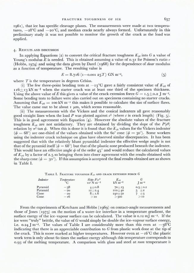
In applying Equations (2) to convert the critical fracture toughness K1C into G a value of Young's modulus E is needed. This is obtained assuming a value of 0.31 for Poisson's ratio v
(Hobbs, 1974) and using the data given by Dantl ( 1968) for the dependence of shear modulus as a function of temperature. The resulting value is
E = 8.716 (1-0.001 25 T ) GN m-z, (5)
where T is the temperature in degrees Celsius. (i) The few three-point bending tests at - 13°C gave a fairly consistent value of K,c of
116 ± 13 kN m- } when the starter crack was at least one third of the specimen thickness. Using the above value of E this gives a value of the crack extension force G = 1.5 ± 0.2 ] m-Z. Some bending tests to fai lure were also carried out on specimens containing no starter cracks. Assuming that K lc = 100 kN m- 3 this makes it possible to calculate the size of surface flaws. The value came out to be about I fLm , which seems reasonable.
(ii) The measurements with the Vickers and the conical indenters all gave reasonably good straight lines when the load P was plotted against c] (where c is crack length) (Fig. 5). This is in good agreement with Equation (4). However the absolute values of the fracture toughness K lc are not satisfactory. They are obtained by dividing the slope of the P (c i ) relation by 7T ~ tan <j;. When this is done it is found that the Klc values for the Vickers indenter (<j; = 68°) are one-third of the values obtained with the 60° cone (<j; = 30°). Some workers using the indenter crack technique on glass have observed similar discrepancies. It has been suggested that with the relatively blunt pyramidal indenter the effective wedge angle is not that of the pyramid itself (.p = 68°) but that of the plastic zone produced beneath the indenter. This would have an effective angle <j; of the order 45° and would reduce the calculated values of K l c by a factor of 2.5 so bringing them into closer agreement with the results obtained with the sharp cone (.p = 30°). If this assumption is accepted the final results obtained are as shown in Table 1.
TABLE 1. FRACTURE TOUGHNESS K, c AND CRACK EXTENSION FORCE G
Indenter T emperatllre Slope P/ct K 1c G cC 105 N m- t kN m-t J m-2
Pyramid - 38 4 ± 0.8 70 ± IS 0·S ± 0.2 Pyramid - 20 12 ± 2·4 210 ± 40 S ± 2 Cone - '20 8± 1.6 240 ± SO 7 ± 3 Cone - 16 > 10 > 300 > 10
From the experiments of Ketcham and Hobbs ( 1969) on contact-angle measurements and those of ]ones (1973) on the motion of a water- ice interface in a temperature gradient, the surface energy of the ice- vapour surface can be calculated. The value is 0.12 m] m - 2 . If the ice were "truly" brittle, the value of G would simply be double the ice-vapour surface energy, i.e. 0.24] m-Z. The values of Table I are considerably more than this even at - 38°C indicating that there is an appreciable contribution to G from plastic work done at the tip of the crack. This is more marked at higher temperatures. However even at - 16°C the plastic work term is only a bout 60 times the surface energy a lthough this temperature corresponds to 0.93 of the melting temperature. A comparison with glass and steel at room temperature is

JO U RNAL OF GLAC I OLOGY
therefore not particularly relevant. A comparison with a plas tic such as P.M.M.A. is more meaningful (see Table II) . At room temperature the surface-energy term is of order 0. 1 J m- 2
whereas G is of order 300 J m- 2 •
T hese results are compared with those obtained by Liu and Loop and by Gold in Table II and Figure 6. As m entioned previously, Liu and Loop used compact tensile specimens and wedge-opening specimens (see F ig . I ) . Their results may depend on grain size as well as on strain-rate but their general ra nge of values of G- of order 1- 5 J m - z- resemble those quoted
TABLE 11. FRACTURE TOUGHNESS VALUES OF ICE: SUMMARY
Author
H . W. Liu and L. 'vV. Loop (priva te communication)
Cold (1963) This paper T his paper, see T a bl e I
For glass sleel P.M.M.A.
w u Cl:
~
T °C
- 45 to - 4
- 12 to - 4 - 12 to - 4
- 16·7 - 13 - 38 - 20 - 16
20 20 20
K, c kNm- t
140 to 100
177 to 222 123 to 149 53 to 62 116± 13 55 to 85
170 to 290 > 300
490 98000
"'" z 2.O o Vi z UJ ~ X W
'" U <! Cl: U
1.0
GOLD[1963} = LlU AND LOOP [1976} t GOODMAN ~
-50
G M ethod oJ test J m-'
3 to 1 Compact tension specimen (var ious load-ing rates)
3.6 to 5.6 Wedge op ening 1. 7 to 2.5 Crack a rres t 0·3 to 0.4 Thermal shock 1.5 ± 0· 3 Three-point bend test 0 ·5 ± 0.2 Med ia n crack (pyramid) 6 ± 3 Media n crack (pyramid a nd cone)
> 10 Median crack (cone) 3·5
42000 300
' 1 t' " '" 3 POINT I 1 ""': f ""10, BENDING~, ~ T
" -1
--- ~o' 1 f50 ---~ I ---50
1 ,-
lTT7l THERMAL LL.L.LI SHOCK
00 QC
Fig. 6. Crack ex tension Jorce G as a junction cif temperature jor various test methods involving large specimens.

FRA CTU R E T O U GHN ESS O F I CE
in T a ble 1. Gold's results obta ined from thermal crack experiments are generall y lower, 0.3 to 0.4 J m - 2 • However the main difference between the results ofLiu a nd Loop and those quoted h ere lies in the dependence of G on tempera ture. They find tha t G increases as the tempera ture is reduced. By contrast the results of T a ble I indicate a m arked reduction in G as the tempera ture is reduced. This would be expected if the colder ice is m ore " truly" brittle a nd involves less plasti c work during crack propagation. This conclusion does however dep end o n the de ta iled interpre ta tion of indentation crack measurem ents.
5. S UMMA RY AND CO NC LUSIO NS
This pap er provides a brief review of earlier work on the fracture toughness K and the c rack extension force G of ice, and includes a preliminar y a ccount of som e new experiments in this field. The qua ntity G is essentia lly a measure of the energy required to propagate a crack in the solid . For a truly brittle solid the stresses genera ted a round the tip of the crack are g iven by a n explicit elastic solution and G is equal to twice the surface energy of the solid. If however plastic fl ow and creep occur a t the crack tip, the singularity at the tip is modifi ed. This is the situa tion with ice and the process becomes m ore a nd more complicated as creep d eforma tion becomes more significant tha n change of sha pe by crack propagation. For ice this critical condition is reached for stra in-ra te less than a bout IQ - 4 S- I . For a similar reason tempera ture may have a profound effect on the fracture energy.
O ver the broad range 0 to - 40°C, the value of G found from experiments using bulk specimens ra nges from a bout 0. 5 to 5 J m - 2 • In these experiments G appears to increase at lower tempera tures. In experiments using crack propagation under hard indenters the value of G ranges from about 0.5 J m - 2 at - 38°C to - IQ J m - 2 a t - r6°C. H ere the values of G d ecrease a t lower tempera tures. Such a trend might be expected since creep and plastic d eforma tion a t the crack tip ought to be less at lower tempera tures .
T he use of a hard indenter to study fracture toughness of ice provides a very a ttractive technique . M any measurements can be m ade in a single sm a ll specimen so that the bas ic properti es of the specimen a re likely to be more uniform. Furthermore specia l specimen shapes a re not required provided there is a single, reasona bly fl at surface accessible to the inden ter . It might therefore be applicable to field studies . H owever the few m easurements described in this paper show tha t the interpretation of the data demands critical examina tion ; in particular the influence of indenter geometry needs to be clarified. Other pa rameters such as loading rates and tempera ture must a lso be considered . I t i hoped to look into these factors in the near future. In addition a direc t study will be made of the propagation of the crack as it occurs during the indentation process itself.
REFEREN C ES
D antl, G . 1968. Die elastischen M oduln von Eis-E inkristallen. Plrysik der kOlldellsiertell Materie, Bd. 7, H t. 5, p. 390- 97.
Gold, L. \\' . 196 1. Forma tio n of cracks in ice plates by thermal shock. Nature, Vol. 192, TO. 4798, p. 130-3 1. Gold, L. W. 1963. Crack forma tion in ice pla tes by thermal shock. Canadian J ournal of Physics, Vol. 14, No. 10,
p. 1712- 28. Cold, L. "V. 1967. Ti me to for'm a tion of fi rst cracks in ice. ( [11 Oura, H ., ed. Physics of snow and ice : illtemational
cOliference on low temperature science . . . . 1966 . ... Proceedings, Vol. 1 , P t. I. [Sapporo] , Institu te of Low T emperature Science, Hokka ido U niversity, p . 359- 70.)
G riffi th , A. A. 1920. The phenomena of rup ture a nd Aow in solids. Philosophical T ransactions oftlte Royal Society of London, Ser. A, Vol. 22 1, N o. 588, p. 163- 98.
H awkes, 1. , and M ellor, M . 1972 . Deformation a nd fracture of ice under uniaxial stress. J ournal of Glaciology, Vol. 11 , No. 6 1, p. 103-3 1.
H obbs, P . V . 1974. Ice physics. Oxford , Clarendon Press. j ones, D . R. H. 1973. The measurement of solid- liquid interfac ia l energ ies from the shapes of grain bounda ry
grooves. Philoso!Jhico! M agazine, Eighth Ser. , Vol. 27, No. 3, p. 569- 84.

660 J OU RNA L OF GLAC IOLOG Y
Kenny, P. , and Campbell , J. D . 1967. Fracture toughness: an exam ination of the concept in p redicting the fa ilure o f materials. Progress ill Ma/erials Science, Vo!. 13, No. 3, p. 137-8 1.
Ketcha m, W. M ., and H obbs, P . V . 1969. An experimenta l determina tion of the surface energies of ice. Philo-sophical Maga z ine, Eigh th Ser., Vo!. 19, No. 162, p. 11 6 1- 73.
Knott, ] . F. 1973. Fundamentals offrac/ure mechanics. London, Butterwor th . Lawn, B. R ., and Wilshaw, T. R. 1975. Fraclure of brillle solids. Cam bl'idge, University Press. Liebowitz, H. , ed. 1969- 72. Frac/ure: an advanced treatise. New York, Academic Press. 3 vols. Swain, M. V., and Lawn, B. R. 1976. Indenta tion fractw'e in bri ttle rocks a nd glasses. International Journal of
R ock M echanics and Mining Science, Vo!. 13, No. 11 , p. 3 11 - 19. Tabor, D . 1970. T he hardness o f solids. Review of Physics in T echnology, VO!. I , No. 3, p . 145- 79. T urner, C. E. 1975. Yield ing fracture mecha nics. J ournal of Strain AnalYsis, Vo!. 10, No. 4, p . 207- 16. Wu, H . C ., and others. 1976. F racture in the compressio n of columnar gra ined ice, by H. C. Wu, K . ] . Chang a nd
] . Schwarz. Engineering Fracture j\l[echanics, Vo!. 8, No. 2, p . 365- 72 .
DIS C USSIO N
W. B. K AMB: Do you have a detailed m ech a nical model, in terms of the creep properties of ice, to explain the measured G values in terms of the contribution of plastic work near the crack tip ?
D. J. G OODMAN : No. W e do not have a m od el although our experiments are directed towards the understanding of microscopic mecha nisms of fracture. W e would expect fracture mechanisms identified in o ther materials to b e observed in ice.
K AMB: In your experiments do you see any effects of the basal cleavage of ice ?
GOODMAN: In the paper we mention tha t cr acks under the indenter did form along specific crystallographic planes. The size of the m edium crack was a lways smaller tha n the grain size.
A. HIGASHI: What was the strain-rate of your fracture exp eriments? F racture toughness may be dependent upon the strain-rate. To build a model, evaluation of plastic surface work based on modes of genera tion of dislocations will be essentia l. As I rep orted yesterday, dislocation distribution is d enser behind a crack tip than a t its front.
GOOD MAN : The strain-ra te depends on the distance from the crack tip . T he loading time in most of the experiments was IQ s. In reply to your second r em ark, I thoroughly agree that it is essentia l to understand creep before tackling fracture . There is no doubt that creep plays an impor tant part in controlling processes a t the crack tip . H owever our experimen ts do not show the same large temperature dependence as creep. Careful study of crack surfaces should help to understand what happens as the crack propagates. It will then be clear whether cracks cross grains or occur at gra in boundaries.
J. W . GLEN: In the wa rtime experiments to see if an iceb erg could be used as an aircraft carrier , I believe they found that the results of firing a torpedo at an iceberg were very unpredic ta bl e- sometimes it shattered and som etimes little ha ppened. T his suggests a varia bility in fracture toughness that was not predictable-perha ps your experimen ts may throw light on this, or perhaps they themselves m ay show great sca tter . H ave you a ny comments?
GOOD MAN : Fracture experimen ts always show a wide scatter , and ours are no excep tion. T his demonstra tes the many p a rameters on which the fracture toughness depends. I suspect the torpedo sampled the extent of pre-existing fla ws in the iceberg .