FPGA Radar Guidance - MITweb.mit.edu/6.111/www/f2015/projects/plancher... · FPGA Radar Guidance:...
107
FPGA Radar Guidance: Final Project Report Brian Plancher December 8, 2015
Transcript of FPGA Radar Guidance - MITweb.mit.edu/6.111/www/f2015/projects/plancher... · FPGA Radar Guidance:...

FPGA Radar Guidance:
Final Project Report
Brian Plancher
December 8, 2015

Contents
1 Introduction 2
2 Overview and Motivation 3
2.1 Project Overview . . . . . . . . . . . . . . . . . . . . . . . . . . . . . . . . . 3
2.2 Design Decisions and Motivation . . . . . . . . . . . . . . . . . . . . . . . . 4
2.3 Successes and Challenges . . . . . . . . . . . . . . . . . . . . . . . . . . . . . 5
3 Design and Implementation 6
3.1 Main FPGA . . . . . . . . . . . . . . . . . . . . . . . . . . . . . . . . . . . . 6
3.1.1 Ultrasound Block . . . . . . . . . . . . . . . . . . . . . . . . . . . . . 7
3.1.2 VGA Display Block . . . . . . . . . . . . . . . . . . . . . . . . . . . . 11
3.1.3 Orientation and Path Calculation Block . . . . . . . . . . . . . . . . 14
3.1.4 IR Transmitting Block . . . . . . . . . . . . . . . . . . . . . . . . . . 17
3.2 Rover . . . . . . . . . . . . . . . . . . . . . . . . . . . . . . . . . . . . . . . 18
3.2.1 IR Receiver Block . . . . . . . . . . . . . . . . . . . . . . . . . . . . . 19
3.2.2 Motor Control Block . . . . . . . . . . . . . . . . . . . . . . . . . . . 20
4 Testing 21
5 Conclusion and Recommendations 23
A Bibliography 25
B Verilog Code 26
1
Chapter 1
Introduction
Imagine that NASA’s Curiosity rover suffered a catastrophic failure to its guidance and
communications systems. All that remains of the system is the backup IR communication
receiver. The only system close enough to communicate with Curiosity is the now stationary
Spirit rover which got stuck in some soft soil in 2009 (suspend disbelief that both the rover
came back on-line) which could then communicate back to earth. How could NASA control
the robot’s movements and keep the mission going?
This project is an exploration of a solution to that problem. Namely, I want to have the
stationary device locate the position of the “rover” through ultrasound location sensing and
be able to send it instructions to find its orientation and as a stretch send it to a desired
location by calculating a path between the “rover” and a destination.
Given the hypothetical situation I am proposing, my design is centered around producing a
reliable method to provide location and path communications. NASA would want to make
sure that their design worked and ensured safe passage of the “rover” to its desired location.
Given that, there are a couple of ways in which this project can be modularized in order to
provide mid-way success points along the path toward the ultimate stretch goal of a feedback
based pathfinding algorithm.
2

Chapter 2
Overview and Motivation
2.1 Project Overview
The project can be understood as two interacting systems as shown in Figure 2.1. The
primary system is the main FPGA system which consists of 4 main blocks: the ultrasound
distance block, the orientation and path calculation block, the IR transmitter block, and the
VGA display block. The secondary system is the “rover” system which consists of 2 main
blocks: the IR receiver block, and the motor control block. The blocks at a high level all
operate as their name implies and only do that one task. However, I found that at the end
of the day I needed to insert a main FSM into the Orientation and Path Calculation Block
which also told the Ultrasound Block when to proceed.
Figure 2.1: The high level design of the system
3
2.2 Design Decisions and Motivation
The primary motivation for this project is to explore robotics, signal processing and control
systems and gain experience building systems. I am incredibly interested in the topics and
am trying to pursue further graduate study in those topics. I therefore see this system
as a starting point and testbed for further work. While all of the modules are necessary
to complete the project, multiple modules can have their outputs hard-coded to allow for
testable intermediate steps (e.g., always define the path as a straight line forward). Because
I am starting from a point of limited experience with many of the technologies I am working
with I made a few design decisions to increase the likelihood of completion. For example, I
decided to use IR and sound communication instead of RF communication because I worked
with them in earlier Labs and given the complexity of the system did not want to add
another new technology. It also reduces the need for obtaining extra hardware. I am also
going to work with a two-motor tank platform for the “Rover” base since I already own that
platform. I also already own some Ultrasound sensors that I have been wanting to use that
I am excited to take advantage of in this lab.
At the highest level, the project in its completed form is designed to allow the Main FPGA
to leverage the ultrasound sensors to calculate the “Rover’s” location (potentially vis-a-vis a
target location) and send it a command over IR to discover its orientation (and potentially
move to the desired location). The system will output VGA to show the location. Timing
delays will only become important if I end up implementing the feedback control but until
then most things are stable and inputs can be pipelined through as many registers as need
to get the calculations done. To begin with I am going to assume away the orientation
calculation and just solve the Ultrasound Block and VGA Block as all other steps are built
on top of that step.
As an important note, I had originally proposed using multiple microphones and a sound
source on the “Rover” to triangulate the position of the “Rover” but found out from Gim
that the Nexys4 board had some limitations that would have made that implementation
very difficult. Therefore I have adjusted to the Ultrasound sensor based approach.
4

2.3 Successes and Challenges
Specific successes and challenges for each module will be explained later in the paper, but
there were a few key overarching successes and challenges that bear mention.
First, I had originally proposed using multiple microphones and a sound source on the
“Rover” to triangulate the position of the “Rover” but found out from Gim that the Nexys4
board had some limitations that would have made that implementation very difficult. There-
fore I have adjusted to the Ultrasound sensor based approach.
Secondly, the biggest challenge I faced was interfacing with the many different hardware
modules I used in my project. Each one had different quirks and created a lot more work
beyond getting the digital logic correct.
Finally, given the Ultrasound approach I think I was quite successfull in the context of
the proposed project. My setup, while only accurate to 30 degrees, does correctly find the
“Rover” and does determine its orientation correctly. It also even correctly calculates the
path it needs to move to reach the target. However, given accuracy limitations in the angle
measurements and in the consistency of traction from the “Rover” the path execution leaves
a bit to be desired. If I had more time, I would have loved to use a stepper motor to take
many more readings with the ultrasound to provide a much more accurate idea of where the
“Rover” was located and to provide a feedback based control to “Rover” to make sure it
reached the target even if it took more than one move. However, since the move was entirely
a stretch goal to begin with, I am quite happy with the overall project.
5

Chapter 3
Design and Implementation
3.1 Main FPGA
This section goes into more detail into each block in the Main FPGA which consists of the
majority of the Verilog code as it not only locates the rover and determines its orientation
and path to travel, but also displays the VGA output. The more detailed block diagram
of the Main FPGA can be found below in Figure 3.1 and futher sections may provide even
more detailed block diagrams.
Figure 3.1: A detailed block diagram showing high level links between the various modules
6

3.1.1 Ultrasound Block
The Ultrasound Block is probably the most important block in the entire system as its
accuracy determines the precision and ability of the rest of the project. The detailed block
diagram can be seen below in Figure 3.2.
Figure 3.2: Ultrasound Detailed Block Diagram
The design was based around the specifications of the HC-SR04 ultrasound module which
I used for the range finding. Given this and the fact that the HC-SR04 ultrasonic module
operates on 5V I dedcided to use the Labkit for my main FPGA to provide easier integration
with its 5V power supply (this is also helpful again for the IR transmission). The way the
module works is when it is triggered it sends out the pulse and determines the location of the
nearest object in its range and then sends the echo output too high for a time proportional
to the distance to the nearest location as show in Figure 3.3 below.
Figure 3.3: Timing diagram of the ultrasound module from ELEC Freaks
7
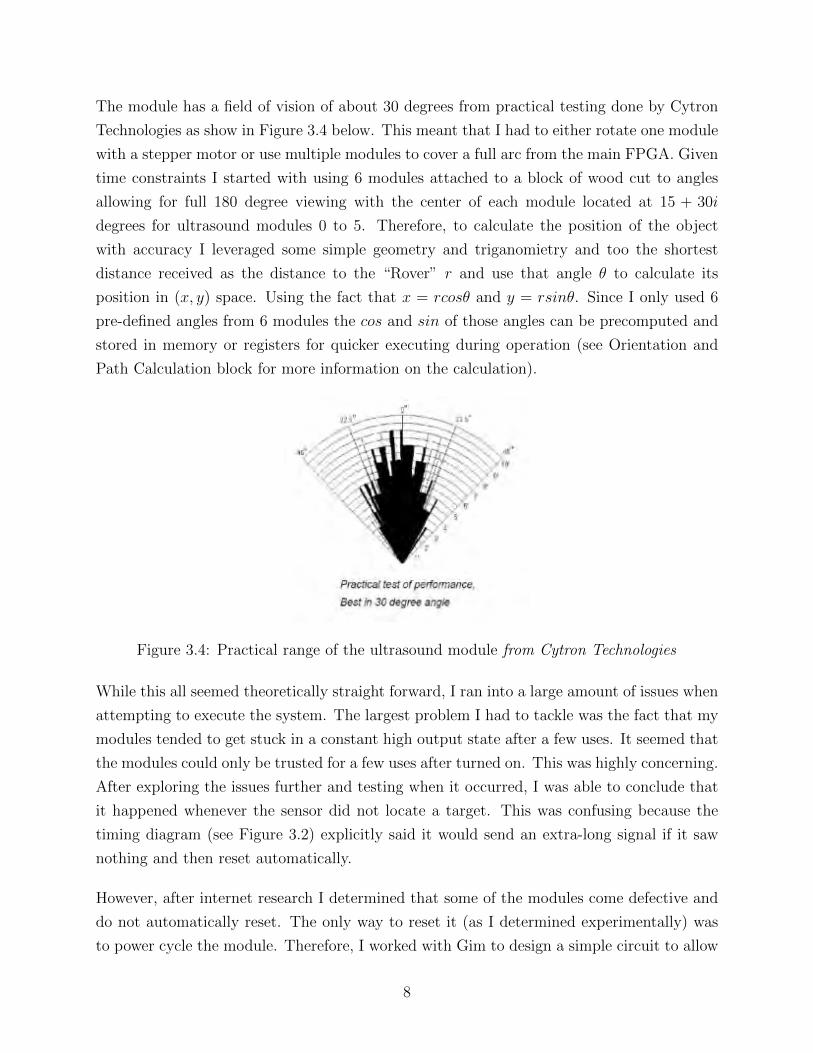
The module has a field of vision of about 30 degrees from practical testing done by Cytron
Technologies as show in Figure 3.4 below. This meant that I had to either rotate one module
with a stepper motor or use multiple modules to cover a full arc from the main FPGA. Given
time constraints I started with using 6 modules attached to a block of wood cut to angles
allowing for full 180 degree viewing with the center of each module located at 15 + 30i
degrees for ultrasound modules 0 to 5. Therefore, to calculate the position of the object
with accuracy I leveraged some simple geometry and triganomietry and too the shortest
distance received as the distance to the “Rover” r and use that angle θ to calculate its
position in (x, y) space. Using the fact that x = rcosθ and y = rsinθ. Since I only used 6
pre-defined angles from 6 modules the cos and sin of those angles can be precomputed and
stored in memory or registers for quicker executing during operation (see Orientation and
Path Calculation block for more information on the calculation).
Figure 3.4: Practical range of the ultrasound module from Cytron Technologies
While this all seemed theoretically straight forward, I ran into a large amount of issues when
attempting to execute the system. The largest problem I had to tackle was the fact that my
modules tended to get stuck in a constant high output state after a few uses. It seemed that
the modules could only be trusted for a few uses after turned on. This was highly concerning.
After exploring the issues further and testing when it occurred, I was able to conclude that
it happened whenever the sensor did not locate a target. This was confusing because the
timing diagram (see Figure 3.2) explicitly said it would send an extra-long signal if it saw
nothing and then reset automatically.
However, after internet research I determined that some of the modules come defective and
do not automatically reset. The only way to reset it (as I determined experimentally) was
to power cycle the module. Therefore, I worked with Gim to design a simple circuit to allow
8

me to control the power to the module with an additional signal. This required the use of
a PNP and an NPN transistor in order to switch on a 5 volt power supply with a 3.3 volt
signal from the labkit (see Figure 3.5 and 3.6).
Figure 3.5: Power switching circuit diagram
Figure 3.6: Wired up power switching circuit
These are now fully operationally and working. The error is completely gone. One note
though is that it greatly slows down the time it takes to determine the position, which while
it doesn’t effect the outcome is not what I was looking for. For future implementers if you
purchase your modules on a steep discount be aware that they may not implement their spec
completely. Be prepared to not assume anything and try all corner cases when they don’t
work.
9

While the power cycle works perfectly this actually spawned another complication; the first
distance measurement after the power cycle was not always accurate and often retruned a
value of 0. Therefore, I did two things to weed out this issue. For one, I decided that a value
of 0 was always an error and threw out the value and would run the module again. Secondly,
I decided to always uese the median of 3 valid distance samples to weed out other errors
and increase overall accuracy. Implementing these further steps in the process removed this
error. The one risk moving forward if I continue to work on the project and impliment more
step angles on the ultrasound with a stepper motor is that 3 may not be enough samples if
error rates increase and I may have to add in more logic to sample 5 or even 7 times. The
good news is that adding in additional simples requires very little change to the code due to
the high level of parameterization of my Verilog modules. I highly suggest a liberal use of
parameters for future implementers. The final set can be seen below in Figure 3.7.
Figure 3.7: Final Ultrasound Setupt
10

3.1.2 VGA Display Block
The VGA Display Block is at its core the same as Lab 3 and utilized the provided code for
that lab. However, it required a lot of custom Verilog in order to display the features that I
wanted to display as seen in the various modules in the block diagram as seen in Figure 3.8.
Figure 3.8: VGA Display Detailed Block Diagram
The core of the VGA block is the VGA Writer module. This module controlls the overall
VGA flow and combinations of the various shapes on the screen. It also pipielines all of
the signals appropriately as each signal completed at a different rate. It takes in the target
location, the rover location and orientation, and the xvga signals and then routs them to
the various submodules for mathematical transforms and pixel creation. First it computes
a polar to cartesian transform on the rover and target location which clears in less than one
clock cycle. This is passed to the blob modules for the unoriented rover and the target which
in turn clear before the end of the first clock cycle. This information is also passed along
with the orientation to the oriented blob module. That module take 4 clock cycles to clear.
Similarly, the grid module which simply takes in the current x and y value and computes
the background polar grid pixel value takes 4 clock cycles to clear. The appropriate rover
pixel depending on if the orientation is known is then alpha blended with the target pixel
and then the output is shown on the screen on top of the grid pixel. Early on, I did not
11
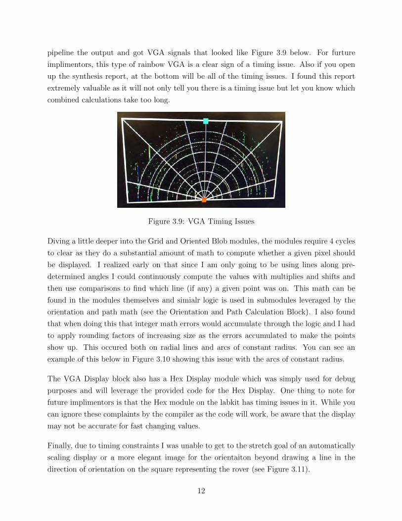
pipeline the output and got VGA signals that looked like Figure 3.9 below. For furture
implimentors, this type of rainbow VGA is a clear sign of a timing issue. Also if you open
up the synthesis report, at the bottom will be all of the timing issues. I found this report
extremely valuable as it will not only tell you there is a timing issue but let you know which
combined calculations take too long.
Figure 3.9: VGA Timing Issues
Diving a little deeper into the Grid and Oriented Blob modules, the modules require 4 cycles
to clear as they do a substantial amount of math to compute whether a given pixel should
be displayed. I realized early on that since I am only going to be using lines along pre-
determined angles I could continuously compute the values with multiplies and shifts and
then use comparisons to find which line (if any) a given point was on. This math can be
found in the modules themselves and simialr logic is used in submodules leveraged by the
orientation and path math (see the Orientation and Path Calculation Block). I also found
that when doing this that integer math errors would accumulate through the logic and I had
to apply rounding factors of increasing size as the errors accumulated to make the points
show up. This occured both on radial lines and arcs of constant radius. You can see an
example of this below in Figure 3.10 showing this issue with the arcs of constant radius.
The VGA Display block also has a Hex Display module which was simply used for debug
purposes and will leverage the provided code for the Hex Display. One thing to note for
future implimentors is that the Hex module on the labkit has timing issues in it. While you
can ignore these complaints by the compiler as the code will work, be aware that the display
may not be accurate for fast changing values.
Finally, due to timing constraints I was unable to get to the stretch goal of an automatically
scaling display or a more elegant image for the orientaiton beyond drawing a line in the
direction of orientation on the square representing the rover (see Figure 3.11).
12

Figure 3.10: VGA Rounding Issues
Figure 3.11: Current Orientation Visual
13

3.1.3 Orientation and Path Calculation Block
At the end of the day, the Orientation and Path Calculation Block first calculates the ori-
entation of the “Rover” by comparing the initial position to a position after a move straight
forward. It then cacluates the path to the target based on this orientation and new location.
When starting to integrate the various modules together I realized that despite my original
plan, in order to keep things simpler, I would need a Main FSM module to control the flow of
data. I decided to house it inside of the Orientation and Path Calculation Block as this block
does most of the heavy lifting and is quite integrated whereas the Ultrasound Block simply
waits to be told to calculate a location and returns that location and the VGA display block
simply displays the current state of knowledge constantly. I then decideded for simplicity
to split out the orientation math and the path math into two seperate modules. I would
later find that I needed to use the orientation math inside of the path math and was very
happy that I could just instantiate another copy of the module for a clean and guaranteed
correct calculation (based on my earlier testing of the orientation block). Further in order to
simplify testing and to pipeline from the start (based on my VGA experience which I started
earlier) I liberally used many sub-modules to calculate part of the math and allow for easier
testing. The detailed block diagram for this block can be seen below in Figure 3.12.
Figure 3.12: Orientation and Path Calculation Block Diagram
While the Main FSM controls the overall flow it is just a simple FSM with straightforward
state transitions. One thing I did learn during the process of making the FSM is that it
is often helpful to introduce one clock cycles delays between states in which you enable a
sub-module and then check if it is done. This is helpful because some of the sub-modules
14
won’t clear their done signal back to 0 until one clock cycle later and the FSM will cause a
state transition too early without the delay.
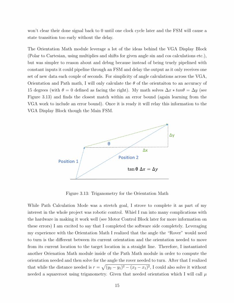
The Orientation Math module leverage a lot of the ideas behind the VGA Display Block
(Polar to Cartesian, using multiplies and shifts for given angle sin and cos calculations etc.),
but was simpler to reason about and debug because instead of being truely pipelined with
constant inputs it could pipeline through an FSM and delay the output as it only receives one
set of new data each couple of seconds. For simplicity of angle calculations across the VGA,
Orientation and Path math, I will only calculate the θ of the orientaiton to an accuracy of
15 degrees (with θ = 0 defined as facing the right). My math solves ∆x ∗ tanθ = ∆y (see
Figure 3.13) and finds the closest match within an error bound (again learning from the
VGA work to include an error bound). Once it is ready it will relay this information to the
VGA Display Block though the Main FSM.
Figure 3.13: Triganometry for the Orientation Math
While Path Calculation Mode was a stretch goal, I strove to complete it as part of my
interest in the whole project was robotic control. Whiel I ran into many complications with
the hardware in making it work well (see Motor Control Block later for more information on
these errors) I am excited to say that I completed the software side completely. Leveraging
my experience with the Orientation Math I realized that the angle the “Rover” would need
to turn is the different between its current orientation and the orientation needed to move
from its current location to the target location in a straight line. Therefore, I instantiated
another Orienation Math module inside of the Path Math module in order to compute the
orientation needed and then solve for the angle the rover needed to turn. After that I realized
that while the distance needed is r =√
(y2 − y1)2 − (x2 − x1)2, I could also solve it without
needed a squareroot using triganometry. Given that needed orientation which I will call µ
15

you can easily solve for the path length as path = (ytarget−yrover)sinµ
(see Figure 3.14).
Figure 3.14: Triganometry for the Path Math
With this in hand and some pipelined calculations through another simple FSM the path
math can easily be calcuated. What I did not have time to implement is a feedback based
control to adjust and correct the commands based on if the previous move was too far or
too short in both angle and distance traveled to get the “Rover” to the correct final location
in as few moves as possible. Ideally once this was implemented, since the “Rover” will be
moving of uniform level terrain it shouldn’t have to greatly adjust the scaling factor and
it should quickly come to an equilibrium solution and provide accurate commands moving
forward once it is calibrated (assuming all of the electronics perform to consistent levels). If
I had more time I would have loved to implement that and other even further stretch goals
could include the ability to add some sophisticated path finding algorithms with obstacles
to the calculation.
I’d also like to include in here that I also wrote a seperate simple top level module which
reads in the switches for the target location and translates it into a value in polar coordinates
like the rest of my values to make it easier for all of these modules to do math on the location
and display it.
16
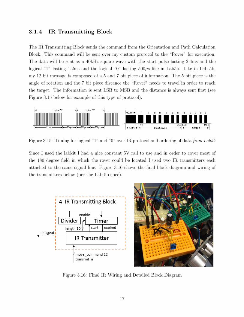
3.1.4 IR Transmitting Block
The IR Transmitting Block sends the command from the Orientation and Path Calculation
Block. This command will be sent over my custom protocol to the “Rover” for execution.
The data will be sent as a 40kHz square wave with the start pulse lasting 2.4ms and the
logical “1” lasting 1.2ms and the logical “0” lasting 500µs like in Lab5b. Like in Lab 5b,
my 12 bit message is composed of a 5 and 7 bit piece of information. The 5 bit piece is the
angle of rotation and the 7 bit piece distance the “Rover” needs to travel in order to reach
the target. The information is sent LSB to MSB and the distance is always sent first (see
Figure 3.15 below for example of this type of protocol).
Figure 3.15: Timing for logical “1” and “0” over IR protocol and ordering of data from Lab5b
Since I used the labkit I had a nice constant 5V rail to use and in order to cover most of
the 180 degree field in which the rover could be located I used two IR transmitters each
attached to the same signal line. Figure 3.16 shows the final block diagram and wiring of
the transmitters below (per the Lab 5b spec).
Figure 3.16: Final IR Wiring and Detailed Block Diagram
17

3.2 Rover
The overall block diagram and final hardware setup for the rover blocks can be seen below
in Figure 3.17.
Figure 3.17: Block Diagram and Final Hardware Setup of the Rover
18

3.2.1 IR Receiver Block
The IR Receiver Block at its core operated identically to the block designed for Lab 5b as
it simply reads in the message from the IR signal and store it into a 5 bit angle register
and 7 bit distance register. Nothing really needed to change in the Verilog from Lab 5b as I
retained almost all of the protocol. However, on the hardware side I needed to use multiple
IR receivers to make sure that the rover could see the signal regardless of its orientation. I
ended up using 3 receivers and then using a 74LS10 and a 74LS04 to combine the signals
together to pass in a single value that the verilog could use as if it was simply a single input.
The circuit can be seen below in Figure 3.16 along with the wiring and the wiring of one of
the receivers (per the Lab 5b spec) that was located on the same board.
Figure 3.18: IR Combination Circuit, Voltage Divider, and Wiring
The one complication I reached is that the Nexys4 board only supplies a 3.3v output and
the IR Recievers need a 5v power supply. I therefore used a 4AA power pack with a voltage
divider (see Figure 3.18 for the circuit diagram) to reduce the voltage from 6v to 5v and
power the IR. I had to play with the resister values to find a dividing amount that provided
enough current to power 3 reciever circuits the 74LS10 and 74LS04 but not too much. I also
found that as the battery started to lose some charge I had to adjust the resisters to allow
for more current flow.
19

3.2.2 Motor Control Block
The Motor Control Block takes as input the decoded angle and distance from the IR Receiver
Block and then powers the motors on the tank base for the appropriate amount of time.
While I thought the motor control would be very simple and while it was simple on the
Verilog side (once I again added in a small main FSM), I ran into a bunch of hardware
complications. For one, I needed an H-Bridge circuit to drive the motors in both directions
to make turns and not simply go in a striaght line. It turned out that the small hobby
motors I was using had a very large current draw and needed more current than a simple
NPN/PNP transistor H-Birdge could provide. I was able to purchase online an L9110S H-
Bridge which when powered from a 6volt 4AA battery pack (seperate from the IR power
pack) could power the motors and make the motors move. However, I found that the only
way to accurately control the pulses was to hook the H-Bridge inputs to NPN transistors to
have them connect one input to ground and complete the circuit only when specified by the
Nexys4 inputs since they were seperately powered by the battery pack. These circuits can
be seen below in Figure 3.19.
Figure 3.19: H-Bridge Controller Circuits
Another bug I found with the motors was that I needed a seperate power supply for each
motor in order to have them be able to run in opposite directions simultaneously and have
the “Rover” turn effectively. When I tried to use the same power supply it created too strong
of a conflicting current drag on the battery and neither motor turned effectively. Now the
“Rover” turns on a dime and can effectively execute commands. The final bug I overcame
was that the rover moved a different amount per clock cycle on different surfaces. I found
that adding manual adjustor values through the switches on the Nexys4 board that can be
updated with the reset switch solves that problem perfectly.
20

Chapter 4
Testing
The basic testing for each module consisted of creating Verilog test benches that can be
simulated with ModelSim. In many cases I had to create both real hardware parameters
to use with the hardware modules in real life and test bench versions to allow modelsim to
complete in a reasonable amount of cycles and allow for intelligent debugging. Combinatorial
test benches were used for the interactions and combinations of the various modules that
interact. I also constantly used the hex displays and the logic analyzer to output data that I
was interested in testing in real life once things checked out in the modelsim runs. Finally I
did substantial user testing to make sure that all of the models worked correctly. Fortunately,
once I got the VGA display working I was able to use it to help me debug what the FPGA
though additional values of certain variables should be. A screenshot from ModelSim and
an image from user testing can be seen below in Figure 4.1 and 4.2.
If you pay close attention to Figure 4.2 below you will notice that I used tape to display
most of the VGA output on the ground so that I could directly and quickly compare the
location of the “Rover” in the real world to the location found on the display.
21

Figure 4.1: ModelSim run example showing multiple ultrasounds in use
Figure 4.2: Full User Testing Setup
22

Chapter 5
Conclusion and Recommendations
Looking back on the project I am very satisfied with the result and very glad that I chose this
project. I have leared so much both in regards to digital logic as applied to real hardware
systems, and in regards to interfacing, debugging, and building simple circuits for analog
hardware systems. I achieved my goal of gain some practical robotics knowledge and am
excited to continue working on similar projects in the future. One regret I have is that I
didn’t have any teammates because I could have reached more stretch goals and made the
project even better if I had a teammate and therefore more time to work on the project. On
the flip side, by working on it alone, I was forced to work with and gain a better fundamental
understanding of every aspect of the project, and I feel like a really understand now every
topic we covered in the course (with the exception of audio, but you can’t have one project
do absolutely everything!).
When evaluating my progress against the plan, I more or less stuck to the schedule that
I specified in my proposal. However, my time estimations were wrong for a number of
modules which was mainly driven by hardware compatability issues. It took a very long
time to determine that just how the HC-SR04 modules were deffective and how to solve that
problem and how to satisfy the current and voltage draw of the motors. I should have built
in much more time for hardware debugging and building. At the same time, the order in
which I built the modules was correct and provided me with many successful midpoints and
allowed for step by step debuggining of the integrated system.
I did plan my modules and the connections between modules in advance, but I did find
that I had to insert a Main FSM module in the middle of all of the logic to provide better
23

debugging and control over the connections and flow of signals especially given the many one
cycle delays I needed to insert into the logic. I should have done this from the beginning as it
realyl created no additional complications and simply made the full program run smoother
and made it easier to debug. I also miscalculated how fanout would slow down many of my
signals given the plethora of modules and high clock-loads and therefore should have tried
a more pipelined archetecture from the start. Given that operating in real time was not a
condition for my project there is no downside to pipelinning the math and I suggest future
implementors do the same from the beginning if they don’t have a timing constraint.
If a future implementor would like to start from where I left off the next steps would be
to adjust all of my modules to use many more measurements (hopefully from non-deffective
HC-SR04s) to provide a more accurate idea of the θ at which the rover is located and
therefore provide a much more accurate path. Also future implementors should look into
using RF instead of IR communication to allow for back and forth communication which
could allow for more streamlined commands without overly conservative delays by the Labkit
and could potentially provide real-time feedback on the path the “Rover” is taking. If a future
implementor doesn’t want to do real-time feedback even a simple feedback system which can
scale future move commands based on how close the rover gets to the target would be a large
improvement over the current algorithm.
That all said, I have effective one shot path finding working with communcation between a
Nexys4 and a Labkit over IR and Ultrasound based range detection that is all displayed on
a VGA. I am quite happy with my work.
24

Appendix A
Bibliography
Cytron Technologies. "User’s Manual".
<https://docs.google.com/document/d/1Y-yZnNhMYy7rwhAgyL_
pfa39RsB-x2qR4vP8saG73rE/edit#>.
ELEC Freaks. "Ultrasonic Ranging Module HC - SR04."
<http://e-radionica.com/productdata/HCSR04.pdf>.
MIT 6.111. "6.111 Lab #5b."
<http://web.mit.edu/6.111/www/f2015/handouts/labs/lab5b.htm>.
25

Appendix B
Verilog Code
The latest version of the code can be found at:
https://github.com/plancherb1/6.111-Final-Project
A PDF print of the current codebase as of the date of publication also follows.
26
C:\Users\Brian\Documents\MIT\6.111\Final Project\all_code_for_print.v Tuesday, December 8, 2015 11:30 PM
`timescale 1ns / 1ps
//////////////////////////////////////////////////////////////////////////////////
// Company: MIT 6.111 Final Project
// Engineer: Brian Plancher
//
// Module Name: rover_location_calculator
// Project Name: FPGA Radar Guidance
//
// Note1: This leverages the get_median_of_3_HCSR04_runs to compute the distance to
// each of the ultrasounds and calculates the angle based on which ultrasound
// reports the closest angle assuming they are located at 15 + 30n degrees
//
//////////////////////////////////////////////////////////////////////////////////
module rover_location_calculator(
input clock,
input reset,
input enable,
input [5:0] ultrasound_response, // uses 6 ultrasounds
output [5:0] ultrasound_trigger, // uses 6 ultrasounds
output [5:0] ultrasound_power, // uses 6 ultrasounds
output reg [11:0] rover_location, // {4 bits for angle, 8 for distance}
output reg done,
output reg [3:0] state, // exposed for debug
output reg [3:0] curr_ultrasound // exposed for debug
);
// connect our module which will compute the distances for each ultrasound
reg run_hcsr04;
wire hcsr04_done;
wire [4:0] hcsr04_state;
wire [7:0] rover_distance_t;
get_median_of_3_HCSR04_runs gm3hcsr04 (.clock(clock),.reset(reset),.enable(run_hcsr04),
.curr_ultrasound(curr_ultrasound),.ultrasound_response(
ultrasound_response),
.ultrasound_trigger(ultrasound_trigger),.ultrasound_pow
er(ultrasound_power),
.rover_distance(rover_distance_t),.done(hcsr04_done),.s
tate(hcsr04_state));
// keep track of the values
reg [7:0] best_distance;
reg [3:0] best_angle;
parameter TOTAL_ULTRASOUNDS = 6;
// fsm parameters
parameter IDLE = 4'h0;
parameter RUN = 4'h1;
parameter PAUSE = 4'h2; // induce a 1 cycle delay to allow the module to get out of the
done state
parameter WAIT = 4'h3;
-1-

C:\Users\Brian\Documents\MIT\6.111\Final Project\all_code_for_print.v Tuesday, December 8, 2015 11:30 PM
parameter REPORT = 4'h4;
// synchronize on the clock
always @(posedge clock) begin
// if reset set back to default
if (reset) begin
state <= IDLE;
done <= 0;
rover_location <= 12'h000;
best_distance <= 0;
best_angle <= 0;
curr_ultrasound <= 0;
end
else begin
// fsm to control the operation
case (state)
// run the helper module to calc the vale for the curr ultrasound
RUN: begin
run_hcsr04 <= 1;
state <= PAUSE;
end
// one cycle delay
PAUSE: state <= WAIT;
// wait for the helper to finish and then potentially save the value
WAIT: begin
run_hcsr04 <= 0;
if (hcsr04_done) begin
// if this is the new best value save it
if ((best_distance == 0) || (rover_distance_t < best_distance)) begin
best_distance <= rover_distance_t;
best_angle <= (curr_ultrasound << 1) + 1; // occurs at 1,3,5,7,9,11 times
15 degrees for 0,1,2,3,4,5 ultrasound numbers
end
// if done then go to report state
if (curr_ultrasound == TOTAL_ULTRASOUNDS - 1) begin
state <= REPORT;
curr_ultrasound <= 0;
end
// else go to next ultrasound
else begin
curr_ultrasound <= curr_ultrasound + 1;
state <= RUN;
end
end
end
// then report out the location
REPORT: begin
// if the best distance is NOTHING_FOUND (all 1s) set to 0 else report as is
if (&best_distance) begin
-2-

C:\Users\Brian\Documents\MIT\6.111\Final Project\all_code_for_print.v Tuesday, December 8, 2015 11:30 PM
rover_location <= 12'h100; // since at origin doesn't matter what angle
end
else begin
rover_location <= {best_angle,best_distance};
end
best_angle <= 0;
best_distance <= 0;
done <= 1;
state <= IDLE;
end
// default to IDLE state
default: begin
// if we are enabled then start the process, else wait
if (enable) begin
state <= RUN;
done <= 0;
best_distance <= 0;
best_angle <= 0;
curr_ultrasound <= 0;
end
end
endcase
end
end
endmodule
`timescale 1ns / 1ps
//////////////////////////////////////////////////////////////////////////////////
// Company: MIT 6.111 Final Project
// Engineer: Brian Plancher
//
// Module Name: Get Median of 3 HCSR04 Runs
// Project Name: FPGA Radar Guidance
//
// Note1: This leverages the run_HCSR04 module to compute the median of 3 runs for
// increased accuracy of measurement
//
//////////////////////////////////////////////////////////////////////////////////
module get_median_of_3_HCSR04_runs(
input clock,
input reset,
input enable,
input [3:0] curr_ultrasound, // which ultrasound to run (0 to 5)
input [5:0] ultrasound_response, // can use up to 6 ultrasounds
output [5:0] ultrasound_trigger, // can use up to 6 ultrasounds
output [5:0] ultrasound_power, // can use up to 6 ultrasounds
output reg [7:0] rover_distance,
output reg done,
output reg [3:0] state // exposed for debug
);
-3-

C:\Users\Brian\Documents\MIT\6.111\Final Project\all_code_for_print.v Tuesday, December 8, 2015 11:30 PM
// get our HCSR04 module
reg run_hcsr04;
wire hcsr04_done;
wire [4:0] hcsr04_state;
wire [7:0] rover_distance_t;
run_HCSR04 us_module (.clock(clock),.reset(reset),.enable(run_hcsr04),
.curr_ultrasound(curr_ultrasound),.ultrasound_response(ultrasound_respon
se),
.ultrasound_trigger(ultrasound_trigger),.ultrasound_power(ultrasound_pow
er),
.rover_distance(rover_distance_t),.done(hcsr04_done),.state(hcsr04_state
));
// get our helper module which computes the median of 3 values
parameter NUM_REPEATS = 3;
reg [1:0] repeat_counter;
reg [7:0] distance_pass_0;
reg [7:0] distance_pass_1;
reg [7:0] distance_pass_2;
wire [7:0] median_distance;
median_3 m3 (.data1(distance_pass_0),.data2(distance_pass_1),
.data3(distance_pass_2),.median(median_distance));
// fsm parameters to run it 3 times
parameter IDLE = 4'h0;
parameter RUN = 4'h1;
parameter PAUSE = 4'h2; // induce a 1 cycle delay to allow the module to get out of
the done state
parameter WAIT = 4'h3;
parameter CALC_MEDIAN = 4'h4; // induce a 1 cycle delay to allow for the median
calculation to clear
parameter REPORT = 4'h5;
// synchronize on the clock
always @(posedge clock) begin
// if reset set back to default
if (reset) begin
state <= IDLE;
done <= 0;
rover_distance <= 8'h00;
repeat_counter <= 0;
end
else begin
// fsm to control the operation
case (state)
// run the HCSR04 module
RUN: begin
run_hcsr04 <= 1;
-4-

C:\Users\Brian\Documents\MIT\6.111\Final Project\all_code_for_print.v Tuesday, December 8, 2015 11:30 PM
state <= PAUSE;
end
// one cycle delay
PAUSE: state <= WAIT;
// wait for the HCSR04 to finish and the save the value
WAIT: begin
run_hcsr04 <= 0;
if (hcsr04_done) begin
// save the value in the correct variable
case (repeat_counter)
1: distance_pass_1 <= rover_distance_t;
2: distance_pass_2 <= rover_distance_t;
default: distance_pass_0 <= rover_distance_t;
endcase
// if we are done then move to the next state
if (repeat_counter == NUM_REPEATS - 1) begin
state <= CALC_MEDIAN;
repeat_counter <= 0;
end
// else run again
else begin
state <= RUN;
repeat_counter <= repeat_counter + 1;
end
end
end
// one cycle delay
CALC_MEDIAN: state <= REPORT;
// report out the result
REPORT: begin
rover_distance <= median_distance;
done <= 1;
state <= IDLE;
end
// default to IDLE state
default: begin
// if we are enabled then start the process, else wait
if (enable) begin
state <= RUN;
repeat_counter <= 0;
done <= 0;
end
end
endcase
end
end
endmodule
-5-

C:\Users\Brian\Documents\MIT\6.111\Final Project\all_code_for_print.v Tuesday, December 8, 2015 11:30 PM
`timescale 1ns / 1ps
//////////////////////////////////////////////////////////////////////////////////
// Company: MIT 6.111 Final Project
// Engineer: Brian Plancher
//
// Module Name: Run HCSR04
// Project Name: FPGA Radar Guidance
//
// Note1: HCSR04 requires about 10 us trigger pulse and then will respond with a
// TTL high signal which is 148 microsecond per inch for 150us to 25ms with
// 38ms representing nothing found. The unit has a range of about 13 feet.
// From extensive testing the units I received had a defect and need to be
// power cycled if they do not find anything for a hard reset. I have found
// that a 1 second power cycle usually rests the unit.
//
// Note2: In this implimentation I report a max value for nothing found since I am
// going to be using the closest match. You may need to adjust this if used
// for other projects.
//
//////////////////////////////////////////////////////////////////////////////////
module run_HCSR04(
input clock,
input reset,
input enable,
input [3:0] curr_ultrasound, // which ultrasound to run (0 to 5)
input [5:0] ultrasound_response, // can use up to 6 ultrasounds
output reg [5:0] ultrasound_trigger, // can use up to 6 ultrasounds
output reg [5:0] ultrasound_power, // can use up to 6 ultrasounds
output reg [7:0] rover_distance,
output reg done,
output reg [3:0] state // exposed for debug
);
// counters and count goals we need
parameter TRIGGER_TARGET = 275; // a little of 10us at 27mhz
parameter DISTANCE_MAX = 1048576; // about 38ms at 27mhz
parameter POWER_CYCLE_TIME = 27000000; // one second at 27mhz
reg [8:0] trigger_count;
reg [19:0] distance_count;
reg [25:0] power_cycle_timer;
// parameter for the physical device
parameter DISTANCE_OFFSET = 5;
parameter NOTHING_FOUND = 20'hF_FFFF;
// fsm state parameters
parameter IDLE = 4'h0; // waiting to do something
parameter TRIGGER = 4'h1; // trigger the module
parameter WAIT_FOR1 = 4'h2; // waiting for distance value
parameter WAIT_FOR0 = 4'h3; // getting in distance value 0 marks end
parameter POWER_CYCLE = 4'h4; // make sure to power cycle in case stuck
-6-

C:\Users\Brian\Documents\MIT\6.111\Final Project\all_code_for_print.v Tuesday, December 8, 2015 11:30 PM
parameter REPORT = 4'h5; // send out the value
// synchronize on the clock
always @(posedge clock) begin
// if reset set back to default
if (reset) begin
state <= IDLE;
done <= 0;
rover_distance <= 8'h00;
ultrasound_trigger <= 6'h00;
ultrasound_power <= 6'hFF;
trigger_count <= 0;
distance_count <= 0;
power_cycle_timer <= 0;
end
else begin
// fsm to control the operation
case (state)
// run the trigger command for the time specified
TRIGGER: begin
// if we have reached our time goal wait for a response
if (trigger_count == TRIGGER_TARGET - 1) begin
state <= WAIT_FOR1;
trigger_count <= 0;
ultrasound_trigger[curr_ultrasound] <= 0;
end
// else keep triggering
else begin
trigger_count <= trigger_count + 1;
end
end
// wait until we see the beginning of the response to start counting
WAIT_FOR1: begin
if(ultrasound_response[curr_ultrasound]) begin
state <= WAIT_FOR0;
distance_count <= 1;
end
end
// count until we see a 0 and then either report the result or powercycle if needed
WAIT_FOR0: begin
// if we see a zero analyze for report
if (~ultrasound_response[curr_ultrasound]) begin
// 148 microsecond per inch means to get inches we divide the count by
// 148*27 = 3996 ~ 4096 so just shift it down 12 times
distance_count <= (distance_count >> 12);
state <= REPORT;
end
// else if we hit max time go to power cycle and report nothing found
else if (distance_count == DISTANCE_MAX - 1) begin
distance_count <= NOTHING_FOUND - DISTANCE_OFFSET;
-7-

C:\Users\Brian\Documents\MIT\6.111\Final Project\all_code_for_print.v Tuesday, December 8, 2015 11:30 PM
state <= POWER_CYCLE;
power_cycle_timer <= 1;
ultrasound_power[curr_ultrasound] <= 0;
end
// else keep counting
else begin
distance_count <= distance_count + 1;
end
end
// power cycle for the appropriate time
POWER_CYCLE: begin
// if we hit our desired time move to report
if (power_cycle_timer == POWER_CYCLE_TIME - 1) begin
power_cycle_timer <= 0;
ultrasound_power[curr_ultrasound] <= 1;
state <= REPORT;
end
// else keep counting
else begin
power_cycle_timer <= power_cycle_timer + 1;
end
end
// report out the distance
REPORT: begin
// if we got a distance of 0 then an error so try again
if (distance_count == 0) begin
state <= TRIGGER;
ultrasound_trigger[curr_ultrasound] <= 1;
done <= 0;
trigger_count <= 1;
distance_count <= 0;
power_cycle_timer <= 0;
end
// else report
else begin
done <= 1;
rover_distance <= distance_count + DISTANCE_OFFSET;
distance_count <= 0;
state <= IDLE;
end
end
// default to IDLE state
default: begin
// if we are enabled then start the process, else wait
if (enable) begin
state <= TRIGGER;
ultrasound_trigger[curr_ultrasound] <= 1;
done <= 0;
trigger_count <= 1;
distance_count <= 0;
-8-

C:\Users\Brian\Documents\MIT\6.111\Final Project\all_code_for_print.v Tuesday, December 8, 2015 11:30 PM
power_cycle_timer <= 0;
end
end
endcase
end
end
endmodule
`timescale 1ns / 1ps
//////////////////////////////////////////////////////////////////////////////////
// Company: MIT 6.111 Final Project
// Engineer: Brian Plancher
//
// Module Name: Median_3
// Project Name: FPGA Radar Guidance
//
//////////////////////////////////////////////////////////////////////////////////
module median_3
(input [19:0] data1,
input [19:0] data2,
input [19:0] data3,
output [19:0] median);
wire min1;
wire max1;
wire comp23;
assign min1 = (data2 > data1) && (data3 > data1);
assign max1 = (data2 < data1) && (data3 < data1);
assign comp23 = data3 > data2;
wire med1;
wire med2;
// if 1 is min or max not 1 else 1
// if 1 is min and 2<3 else if 1 is max and 3<2 then 2
assign med1 = !(min1 || max1);
assign med2 = (min1 && comp23) || (max1 && (!comp23));
// then assign out value
assign median = med1 ? data1 : (med2 ? data2 : data3);
endmodule
`timescale 1ns / 1ps
//////////////////////////////////////////////////////////////////////////////////
// Company: MIT 6.111 Final Project
// Engineer: Brian Plancher
//
// Module Name: VGA Writer
// Project Name: FPGA Radar Guidance
//
// Notes: Based on Pong Game Logic
-9-

C:\Users\Brian\Documents\MIT\6.111\Final Project\all_code_for_print.v Tuesday, December 8, 2015 11:30 PM
//////////////////////////////////////////////////////////////////////////////////
module vga_writer (
input vclock, // 65MHz clock
input reset, // 1 to initialize module
input [11:0] location, // input location of the Rover
input [4:0] orientation, // orientation of the rover
input [11:0] target_location,// location of the target
input new_data, // ready to re-draw and use the new location
input orientation_ready, // ready to draw the orientation
input [10:0] hcount, // horizontal index of current pixel (0..1023)
input [9:0] vcount, // vertical index of current pixel (0..767)
input hsync, // XVGA horizontal sync signal (active low)
input vsync, // XVGA vertical sync signal (active low)
input blank, // XVGA blanking (1 means output black pixel)
output phsync, // output horizontal sync
output pvsync, // output vertical sync
output pblank, // output blanking
//output analyzer_clock, // debug only
//output [15:0] analyzer_data, // debug only
output reg [23:0] pixel // output pixel // r=23:16, g=15:8, b=7:0
);
// we need to delay hxync, vsync, and blank by the same amount as our
// total pipeline time below
parameter PIPELINE_LENGTH = 5;
delayN #(.NDELAY(PIPELINE_LENGTH)) hdelay (.clk(vclock),.in(hsync),.out(phsync));
delayN #(.NDELAY(PIPELINE_LENGTH)) vdelay (.clk(vclock),.in(vsync),.out(pvsync));
delayN #(.NDELAY(PIPELINE_LENGTH)) bdelay (.clk(vclock),.in(blank),.out(pblank));
// turn hcount and vcount into x,y for easier analysis
parameter TOTAL_WIDTH = 1024;
parameter TOTAL_HEIGHT = 768;
wire signed [11:0] x_value;
wire signed [11:0] y_value;
assign x_value = hcount - TOTAL_WIDTH/2;
assign y_value = TOTAL_HEIGHT - vcount;
// parameters to define shapes
parameter BLANK_COLOR = 24'h00_00_00;
parameter GRID_COLOR = 24'hFF_FF_FF;
parameter TARGET_WIDTH = 16;
parameter TARGET_HEIGHT = 16;
parameter TARGET_COLOR = 24'h00_FF_00;
parameter ROVER_HEIGHT = 16;
parameter ROVER_WIDTH = 16;
parameter ROVER_COLOR = 24'hFF_00_00;
parameter ROVER_ORIENTED_COLOR = 24'h00_00_FF;
// and the grid
parameter GRID_LINE_WIDTH = 1;
parameter GRID_HEIGHT = 256;
parameter GRID_WIDTH = 512;
parameter GRID_RIGHT_BORDER = (TOTAL_WIDTH-GRID_WIDTH)/2;
parameter GRID_LEFT_BORDER = -1*GRID_RIGHT_BORDER;
-10-

C:\Users\Brian\Documents\MIT\6.111\Final Project\all_code_for_print.v Tuesday, December 8, 2015 11:30 PM
parameter GRID_BOTTOM_BORDER = (TOTAL_HEIGHT-GRID_HEIGHT)/2;
parameter GRID_TOP_BORDER = TOTAL_HEIGHT - GRID_BOTTOM_BORDER;
// for debug
//assign analyzer_clock = vsync;
//assign analyzer_data = {rover_x[7:0],rover_y[7:0]};
// helpers for the rover and target position update on VSYNC
reg signed [11:0] target_x;
reg signed [11:0] target_y;
wire signed [8:0] temp_target_x;
wire signed [8:0] temp_target_y;
wire signed [11:0] sized_temp_target_x;
wire signed [11:0] sized_temp_target_y;
reg signed [11:0] rover_x;
reg signed [11:0] rover_y;
wire signed [8:0] temp_rover_x;
wire signed [8:0] temp_rover_y;
wire signed [11:0] sized_temp_rover_x;
wire signed [11:0] sized_temp_rover_y;
// helper to compute the polar to cartesian
polar_to_cartesian ptcr (.r_theta(location),.x_value(temp_rover_x),.y_value(temp_rover_y));
assign sized_temp_rover_x = {temp_rover_x[8],temp_rover_x[8],temp_rover_x[8],temp_rover_x};
assign sized_temp_rover_y = {temp_rover_y[8],temp_rover_y[8],temp_rover_y[8],temp_rover_y};
polar_to_cartesian ptct
(.r_theta(target_location),.x_value(temp_target_x),.y_value(temp_target_y));
assign sized_temp_target_x =
{temp_target_x[8],temp_target_x[8],temp_target_x[8],temp_target_x};
assign sized_temp_target_y =
{temp_target_y[8],temp_target_y[8],temp_target_y[8],temp_target_y};
// scaling factor is how big we make the distance between each arc
// we default to 2 but can change it according to the rover and target location
// that is, the rover and target need to be in the grid so therefore scale is the
// min(GRID_HEIGHT/absmax(target_y, rover_y),GRID_WIDTH/absmax(target_x,rover_x))
reg signed [11:0] max_x;
reg signed [11:0] max_y;
// helper function for abs_max needed here
wire [2:0] scale_factor;
assign scale_factor = 10;
// instantiate the grid
wire [23:0] grid_pixel;
grid #(.GRID_COLOR(GRID_COLOR),.BLANK_COLOR(BLANK_COLOR),
.BOTTOM_BORDER(GRID_BOTTOM_BORDER),.TOP_BORDER(GRID_TOP_BORDER),
.LEFT_BORDER(GRID_LEFT_BORDER),.RIGHT_BORDER(GRID_RIGHT_BORDER),
.LINE_WIDTH(GRID_LINE_WIDTH))
grid(.x_value(x_value),.y_value(y_value),.pixel(grid_pixel),.clock(vclock));
// instantiate the target
wire [23:0] target_pixel;
blob
#(.WIDTH(TARGET_WIDTH),.HEIGHT(TARGET_HEIGHT),.COLOR(TARGET_COLOR),.BLANK_COLOR(BLANK_COLOR))
-11-

C:\Users\Brian\Documents\MIT\6.111\Final Project\all_code_for_print.v Tuesday, December 8, 2015 11:30 PM
target(.center_x(target_x),.center_y(target_y),.x_value(x_value),.y_value(y_value),.pixel
(target_pixel));
// instantiate the square rover
wire [23:0] rover_pixel_noO;
blob
#(.WIDTH(ROVER_WIDTH),.HEIGHT(ROVER_HEIGHT),.COLOR(ROVER_COLOR),.BLANK_COLOR(BLANK_COLOR))
rover_noO(.center_x(rover_x),.center_y(rover_y),.x_value(x_value),.y_value(y_value),.pixe
l(rover_pixel_noO));
//instantiate the triangle rover
wire [23:0] rover_pixel_yesO;
oriented_blob #(.WIDTH(ROVER_WIDTH),.HEIGHT(ROVER_HEIGHT),.COLOR(ROVER_ORIENTED_COLOR),
.BLANK_COLOR(BLANK_COLOR),.INDICATOR_COLOR(ROVER_COLOR))
rover_yesO(.center_x(rover_x),.center_y(rover_y),.x_value(x_value),.y_value(y_value),.pix
el(rover_pixel_yesO),
.orientation(orientation),.clock(vclock));
// helpers for the delays
reg [23:0] target_pixel2;
reg [23:0] target_pixel3;
reg [23:0] target_pixel4;
reg [23:0] target_pixel5;
reg [23:0] rover_pixel_noO2;
reg [23:0] rover_pixel_noO3;
reg [23:0] rover_pixel_noO4;
reg [23:0] rover_pixel;
reg [23:0] grid_pixel2;
// helper modules for ALPHA_BLEND
parameter ALPHA_M = 2;
parameter ALPHA_N = 4;
parameter ALPHA_N_LOG_2 = 2;
wire [23:0] overlap_pixel;
alpha_blend #(.ALPHA_M(ALPHA_M),.ALPHA_N(ALPHA_N),.ALPHA_N_LOG_2(ALPHA_N_LOG_2))
ab(.pixel_1(rover_pixel),.pixel_2(target_pixel5),.overlap_pixel(overlap_pixel));
// we then pipeline the rest of the VGA display because it takes too long to clear
always @(posedge vclock) begin
// when we reset move the rover off of the screen and wait for ultrasound to update
if (reset) begin
rover_x <= 0;
rover_y <= GRID_BOTTOM_BORDER/2;
end
else begin
// only actually update the position every screen refresh for both the target and the
rover
if (!vsync) begin
// else for the location of the "Rover" we only update when we have valid new
information
if (new_data | orientation_ready) begin
-12-

C:\Users\Brian\Documents\MIT\6.111\Final Project\all_code_for_print.v Tuesday, December 8, 2015 11:30 PM
// save the updated rover location
rover_x <= sized_temp_rover_x * scale_factor;
rover_y <= (sized_temp_rover_y * scale_factor) + GRID_BOTTOM_BORDER;
end
// always update the target to the state of the switches
target_x <= sized_temp_target_x * scale_factor;
target_y <= (sized_temp_target_y * scale_factor) + GRID_BOTTOM_BORDER;
// UPDATE THE SCALE FACTOR ???? ----- STRETCH GOAL WOULD GO HERE USING MAXX AND MAXY
end
// else enter the pipelined FSM to calculate all of the correct pixel values
else begin
// Get the values back from the helper functions
// grid takes 4 clock cycles so delay 1 for rover combos
// triangle (oriented target) takes 4 clock cycles so delay 0
// blobs (un-oriented rover and target) take 1 cycle so delay 4
// alpha blend takes 1 clock cycle
// final output is delayed then by 5 clock cycles
// 1st clock cycle only the blobs clearrover_pixel_yesO
rover_pixel_noO2 <= rover_pixel_noO;
target_pixel2 <= target_pixel;
// 2nd clock cylce still only the blobs clear so delay again
rover_pixel_noO3 <= rover_pixel_noO2;
target_pixel3 <= target_pixel2;
// 3rd clock cycle still only the blobs clear so delay again
rover_pixel_noO4 <= rover_pixel_noO3;
target_pixel4 <= target_pixel3;
// 4th clock cycle create rover pixel and delay target once more as triangle
cleared and delay grid 1
rover_pixel <= orientation_ready ? rover_pixel_yesO : rover_pixel_noO4;
target_pixel5 <= target_pixel4;
grid_pixel2 <= grid_pixel;
// 5th clock cycle alpha blend and display the grid as alpha blend is 1 cycle and
grid is now done
pixel <= |overlap_pixel ? overlap_pixel : grid_pixel2;
end
end
end
endmodule
`timescale 1ns / 1ps
////////////////////////////////////////////////////////////////////////////////
//
// xvga: Generate XVGA display signals (1024 x 768 @ 60Hz)
//
////////////////////////////////////////////////////////////////////////////////
module xvga(input vclock,
output reg [10:0] hcount, // pixel number on current line
-13-

C:\Users\Brian\Documents\MIT\6.111\Final Project\all_code_for_print.v Tuesday, December 8, 2015 11:30 PM
output reg [9:0] vcount, // line number
output reg vsync,hsync,blank);
// horizontal: 1344 pixels total
// display 1024 pixels per line
reg hblank,vblank;
wire hsyncon,hsyncoff,hreset,hblankon;
assign hblankon = (hcount == 1023);
assign hsyncon = (hcount == 1047);
assign hsyncoff = (hcount == 1183);
assign hreset = (hcount == 1343);
// vertical: 806 lines total
// display 768 lines
wire vsyncon,vsyncoff,vreset,vblankon;
assign vblankon = hreset & (vcount == 767);
assign vsyncon = hreset & (vcount == 776);
assign vsyncoff = hreset & (vcount == 782);
assign vreset = hreset & (vcount == 805);
// sync and blanking
wire next_hblank,next_vblank;
assign next_hblank = hreset ? 0 : hblankon ? 1 : hblank;
assign next_vblank = vreset ? 0 : vblankon ? 1 : vblank;
always @(posedge vclock) begin
hcount <= hreset ? 0 : hcount + 1;
hblank <= next_hblank;
hsync <= hsyncon ? 0 : hsyncoff ? 1 : hsync; // active low
vcount <= hreset ? (vreset ? 0 : vcount + 1) : vcount;
vblank <= next_vblank;
vsync <= vsyncon ? 0 : vsyncoff ? 1 : vsync; // active low
blank <= next_vblank | (next_hblank & ~hreset);
end
endmodule
`timescale 1ns / 1ps
//////////////////////////////////////////////////////////////////////////////////
//
// Engineer: Gim Hong and Brian Plancher
//
// Module Name: blob
//
// Additional Comments: Updated by Brian Plancher 11/3/15 to use my custom geometry
// and to pull location as the center of the square
//
//////////////////////////////////////////////////////////////////////////////////
module blob
#(parameter WIDTH = 64,HEIGHT = 64,COLOR = 24'hFF_FF_FF,BLANK_COLOR=24'h00_00_00)
(input signed [11:0] center_x,
input signed [11:0] x_value,
input signed [11:0] center_y,
-14-
C:\Users\Brian\Documents\MIT\6.111\Final Project\all_code_for_print.v Tuesday, December 8, 2015 11:30 PM
input signed [11:0] y_value,
output reg [23:0] pixel);
parameter WIDTH_D2 = WIDTH/2;
parameter HEIGHT_D2 = HEIGHT/2;
wire in_square;
assign in_square = (x_value >= (center_x-WIDTH_D2) && x_value < (center_x+WIDTH_D2)) &&
(y_value >= (center_y-HEIGHT_D2) && y_value < (center_y+HEIGHT_D2));
always @(*) begin
if (in_square) begin
pixel = COLOR;
end
else begin
pixel = BLANK_COLOR;
end
end
endmodule
`timescale 1ns / 1ps
//////////////////////////////////////////////////////////////////////////////////
// Company: MIT 6.111 Final Project
// Engineer: Brian Plancher
//
// Module Name: Grid
// Project Name: FPGA Radar Guidance
//
// Notes: Display the lines for the various angles (starting at 15 every 30) and
// 6 circles of parameter defined radius that make up the background grid image
// only involves singular multiplies and bitshift/add/sub which should clear in one
// clock cycle which is what we need
//////////////////////////////////////////////////////////////////////////////////
module grid
#(parameter BLANK_COLOR = 24'h00_00_00, GRID_COLOR = 24'hFF_00_00,
LEFT_BORDER = -128, RIGHT_BORDER = 128,
TOP_BORDER = 640, BOTTOM_BORDER = 128, LINE_WIDTH = 1)
(input signed [11:0] x_value,
input signed [11:0] y_value,
input clock,
output reg [23:0] pixel);
// helpers for BORDERS and E Values
reg on_border;
reg out_of_border;
parameter BORDER_WIDTH = 3; // give border width of BORDER_WIDTH extending out
// get our effective y and x and r values
reg signed [11:0] y_value_e;
reg signed [11:0] x_value_e;
// parameters and helpers for test values and get radius
-15-

C:\Users\Brian\Documents\MIT\6.111\Final Project\all_code_for_print.v Tuesday, December 8, 2015 11:30 PM
reg signed [31:0] test_15deg; // large bit size to multiply and shift
reg signed [31:0] test_45deg; // large bit size to multiply and shift
reg signed [31:0] test_75deg; // large bit size to multiply and shift
reg [31:0] r_e; // large bit size to multiply
// keep passign the current y_e and borders
reg signed [11:0] y_value_e2;
reg on_border2;
reg out_of_border2;
// parameters and helpers for on radial line and on arc
reg on_arc;
parameter R_7 = 224*224;
parameter R_6 = 192*192;
parameter R_5 = 160*160;
parameter R_4 = 128*128;
parameter R_3 = 96*96;
parameter R_2 = 64*64;
parameter R_1 = 32*32;
// note: tan 105 = -tan 75, tan 135 = -tan 45, tan 165 = -tan 15
reg on_15_pos;
reg on_15_neg;
reg on_45_pos;
reg on_45_neg;
reg on_75_pos;
reg on_75_neg;
// note from experimentation I have found that I need larger widths to account for
// rounding as the angle gets steeper adn width bigger
parameter ROUNDING_FACTOR = 64;
parameter ROUNDING_FACTOR_2 = 2*ROUNDING_FACTOR;
parameter ROUNDING_FACTOR_4 = 4*ROUNDING_FACTOR;
parameter RADIAL_ROUNDING_FACTOR = 3;
// keep passing borders
reg on_border3;
reg out_of_border3;
// this all needs to be pipelined as it won't complete in one clock cycle
always @(posedge clock) begin
// phase 1: borders and E values
y_value_e <= y_value - BOTTOM_BORDER;
x_value_e <= x_value;
on_border <=(x_value - RIGHT_BORDER >= 0) | (x_value - LEFT_BORDER <= 0) |
(y_value - TOP_BORDER >= 0) | (y_value - BOTTOM_BORDER <= 0);
out_of_border <= (x_value > RIGHT_BORDER + BORDER_WIDTH) | (x_value < LEFT_BORDER -
BORDER_WIDTH) |
(y_value > TOP_BORDER + BORDER_WIDTH) | (y_value < BOTTOM_BORDER -
BORDER_WIDTH);
// phase 2 get TEST_VALUES and get radius
test_15deg <= (x_value_e*17) >>> 6; // tan 15 is about 17/64
test_45deg <= x_value_e; // tan 45 = 1
test_75deg <= (x_value_e*240) >>> 6; // tan 75 is about 240/64
r_e <= x_value_e*x_value_e + y_value_e*y_value_e;
-16-

C:\Users\Brian\Documents\MIT\6.111\Final Project\all_code_for_print.v Tuesday, December 8, 2015 11:30 PM
// keep y and the borders
y_value_e2 <= y_value_e;
on_border2 <= on_border;
out_of_border2 <= out_of_border;
// phase 3 ON_RADIAL and ON_ARC
on_15_pos <= ((test_15deg - y_value_e2) - LINE_WIDTH <= 0) &&
((test_15deg - y_value_e2) + LINE_WIDTH >= 0);
on_15_neg <= ((test_15deg + y_value_e2) - LINE_WIDTH <= 0) &&
((test_15deg + y_value_e2) + LINE_WIDTH >= 0);
on_45_pos <= ((test_45deg - y_value_e2) - LINE_WIDTH <= 0) &&
((test_45deg - y_value_e2) + LINE_WIDTH >= 0);
on_45_neg <= ((test_45deg + y_value_e2) - LINE_WIDTH <= 0) &&
((test_45deg + y_value_e2) + LINE_WIDTH >= 0);
on_75_pos <= ((test_75deg - y_value_e2) - (LINE_WIDTH*RADIAL_ROUNDING_FACTOR) <= 0) &&
((test_75deg - y_value_e2) + (LINE_WIDTH*RADIAL_ROUNDING_FACTOR) >= 0);
on_75_neg <= ((test_75deg + y_value_e2) - (LINE_WIDTH*RADIAL_ROUNDING_FACTOR) <= 0) &&
((test_75deg + y_value_e2) + (LINE_WIDTH*RADIAL_ROUNDING_FACTOR) >= 0);
on_arc <= ((r_e - R_1 - (LINE_WIDTH*ROUNDING_FACTOR) <= 0) && (r_e - R_1 +
(LINE_WIDTH*ROUNDING_FACTOR) >= 0)) |
((r_e - R_2 - (LINE_WIDTH*ROUNDING_FACTOR_2) <= 0) && (r_e - R_2 +
(LINE_WIDTH*ROUNDING_FACTOR_2) >= 0)) |
((r_e - R_3 - (LINE_WIDTH*ROUNDING_FACTOR_2) <= 0) && (r_e - R_3 +
(LINE_WIDTH*ROUNDING_FACTOR_2) >= 0)) |
((r_e - R_4 - (LINE_WIDTH*ROUNDING_FACTOR_2) <= 0) && (r_e - R_4 +
(LINE_WIDTH*ROUNDING_FACTOR_2) >= 0)) |
((r_e - R_5 - (LINE_WIDTH*ROUNDING_FACTOR_4) <= 0) && (r_e - R_5 +
(LINE_WIDTH*ROUNDING_FACTOR_4) >= 0)) |
((r_e - R_6 - (LINE_WIDTH*ROUNDING_FACTOR_4) <= 0) && (r_e - R_6 +
(LINE_WIDTH*ROUNDING_FACTOR_4) >= 0)) |
((r_e - R_7 - (LINE_WIDTH*ROUNDING_FACTOR_4) <= 0) && (r_e - R_7 +
(LINE_WIDTH*ROUNDING_FACTOR_4) >= 0));
on_border3 <= on_border2;
out_of_border3 <= out_of_border2;
// phase 4 Report out the value
// test to see if not out of border and on a border, radial line, or arc
if ((!out_of_border3) && (on_border3 | on_arc | on_15_pos | on_15_neg |
on_45_pos | on_45_neg | on_75_pos | on_75_neg)) begin
pixel <= GRID_COLOR;
end
else begin
pixel <= BLANK_COLOR;
end
end
endmodule
`timescale 1ns / 1ps
//////////////////////////////////////////////////////////////////////////////////
// Company: MIT 6.111 Final Project
// Engineer: Brian Plancher
//
-17-
C:\Users\Brian\Documents\MIT\6.111\Final Project\all_code_for_print.v Tuesday, December 8, 2015 11:30 PM
// Module Name: Oriented Blob
// Project Name: FPGA Radar Guidance
//
// Notes: Based off of Blob from Lab3
//////////////////////////////////////////////////////////////////////////////////
module oriented_blob
#(parameter WIDTH = 64,HEIGHT = 64,COLOR = 24'hFF_FF_FF,
BLANK_COLOR=24'h00_00_00,INDICATOR_COLOR = 24'h00_FF_00)
(input signed [11:0] center_x,
input signed [11:0] x_value,
input signed [11:0] center_y,
input signed [11:0] y_value,
input [4:0] orientation,
input clock,
output reg [23:0] pixel);
// parameters needed to define lines and directions every 15 degrees
parameter WIDTH_D2 = WIDTH/2;
parameter HEIGHT_D2 = HEIGHT/2;
parameter D180 = 12;
parameter D360 = 24;
// Phase 1 helpers
reg in_square;
reg signed [11:0] delta_x;
reg signed [11:0] delta_y;
reg signed [11:0] abs_delta_x;
reg signed [11:0] abs_delta_y;
reg [31:0] orientation_quadrant; // large bit size to multiply and shift
reg [4:0] orientation2;
// Phase 2 helpers
// while we are solving for 00 to 90 we are really solving for 00 to 90 + 90n to get
// all for directions and then using a quadrant test later
// for 00 and 90 need some x or y and 0 of the other
reg test_on_00;
reg test_on_45;
reg test_on_90;
reg signed [31:0] test_on_15; // large bit size to multiply and shift
reg signed [31:0] test_on_30; // large bit size to multiply and shift
reg signed [31:0] test_on_60; // large bit size to multiply and shift
reg signed [31:0] test_on_75; // large bit size to multiply and shift
reg [1:0] orientation_quadrant2;
reg signed [11:0] delta_x2;
reg signed [11:0] delta_y2;
reg in_square2;
reg [4:0] orientation3;
// Phase 3 helpers
// we need to apply a ROUNDING factor for the bit shift rounding
parameter ROUNDING_FACTOR = 2;
parameter ROUNDING_FACTOR_2 = 2 * ROUNDING_FACTOR;
reg on_00;
-18-

C:\Users\Brian\Documents\MIT\6.111\Final Project\all_code_for_print.v Tuesday, December 8, 2015 11:30 PM
reg on_15;
reg on_30;
reg on_45;
reg on_60;
reg on_75;
reg on_90;
// keep the quadrant and orientation and in square around
reg right_quadrant;
reg [2:0] orientation_angle;
reg in_square3;
// we need to pipeline all of this as it doesn't clear fast enough
always @(posedge clock) begin
// Phase 1: get in square and abs_deltas and deltas and quadrant
in_square <= (x_value >= (center_x-WIDTH_D2) && x_value < (center_x+WIDTH_D2)) &&
(y_value >= (center_y-HEIGHT_D2) && y_value < (center_y+HEIGHT_D2));
delta_x <= x_value - center_x;
delta_y <= y_value - center_y;
abs_delta_x <= (center_x > x_value) ? (center_x - x_value) : (x_value - center_x);
abs_delta_y <= (center_y > y_value) ? (center_y - y_value) : (y_value - center_y);
// orientation 0 = 0, 1 = 15 ... 24 = 90 so orientation / 6 == quadrant
orientation_quadrant <= (orientation * 170) >> 10;// 1/6 is about 170/1024
orientation2 <= orientation;
// Phase 2 calc all lines we care about, get angle and make sure we are in right quadrant
test_on_00 <= (!(abs_delta_x == 0)) && (abs_delta_y == 0); // change in x but none in y
test_on_90 <= (abs_delta_x == 0) && (!(abs_delta_y == 0)); // change in y but none in x
test_on_45 <= abs_delta_x == abs_delta_y; // for 45 we need delta x = delta y
test_on_15 <= ((abs_delta_x*17) >>> 6) - abs_delta_y; // tan 15 is about 17/64
test_on_30 <= ((abs_delta_x*37) >>> 6) - abs_delta_y; // tan 75 is about 37/64
test_on_60 <= ((abs_delta_x*111) >>> 6) - abs_delta_y; // tan 75 is about 111/64
test_on_75 <= ((abs_delta_x*240) >>> 6) - abs_delta_y; // tan 75 is about 240/64
// save values for next phase
orientation_quadrant2 <= orientation_quadrant[1:0];
in_square2 <= in_square;
orientation3 <= orientation2;
delta_x2 <= delta_x;
delta_y2 <= delta_y;
// phase 3 find if we are on the lines and in the right quadrant and get the angle
on_00 <= test_on_00;
on_90 <= test_on_90;
on_45 <= test_on_45;
on_15 <= (test_on_15 - ROUNDING_FACTOR <= 0) &&
(test_on_15 + ROUNDING_FACTOR >= 0);
on_30 <= (test_on_30 - ROUNDING_FACTOR <= 0) &&
(test_on_30 + ROUNDING_FACTOR >= 0);
on_60 <= (test_on_60 - ROUNDING_FACTOR <= 0) &&
(test_on_60 + ROUNDING_FACTOR >= 0);
on_75 <= (test_on_75 - ROUNDING_FACTOR_2 <= 0) &&
(test_on_75 + ROUNDING_FACTOR_2 >= 0);
case (orientation_quadrant2)
-19-
C:\Users\Brian\Documents\MIT\6.111\Final Project\all_code_for_print.v Tuesday, December 8, 2015 11:30 PM
// base 0 so 1 is 2nd quadrant
1: begin
right_quadrant <= (delta_x2 <= 0) && (delta_y2 >=0) && in_square2;
orientation_angle <= D180 - orientation3; // 12 is 180 which is 0 (0), 7 is 105
which is 75 (5)
end
// base 0 so 2 is 3nd quadrant
2: begin
right_quadrant <= (delta_x2 <= 0) && (delta_y2 <=0) && in_square2;
orientation_angle <= orientation3 - D180; // 18 is 270 which is 90 (6), 13 is 195
which is 15 (1)
end
// base 0 so 3 is 4th quadrant
3: begin
right_quadrant <= (delta_x2 >= 0) && (delta_y2 <=0) && in_square2;
orientation_angle <= D360 - orientation3; // 24 is 360 which is 0 (0), 23 is 345
which is 15 (1)
end
// default to 1st quadrant
default: begin
right_quadrant <= (delta_x2 >= 0) && (delta_y2 >=0) && in_square2;
orientation_angle <= orientation3;
end
endcase
in_square3 <= in_square2;
// Phase 4 is output the result based on angle
if (right_quadrant) begin
case (orientation_angle)
// 1 is 15 degrees
1: begin
pixel <= on_15 ? INDICATOR_COLOR : COLOR;
end
// 2 is 30 degrees
2: begin
pixel <= on_30 ? INDICATOR_COLOR : COLOR;
end
// 3 is 45 degrees
3: begin
pixel <= on_45 ? INDICATOR_COLOR : COLOR;
end
// 4 is 60 degrees
4: begin
pixel <= on_60 ? INDICATOR_COLOR : COLOR;
end
// 5 is 75 degrees
5: begin
pixel <= on_75 ? INDICATOR_COLOR : COLOR;
end
// 6 is 90 degrees
6: begin
pixel <= on_90 ? INDICATOR_COLOR : COLOR;
end
-20-

C:\Users\Brian\Documents\MIT\6.111\Final Project\all_code_for_print.v Tuesday, December 8, 2015 11:30 PM
// default to 00 degrees
default: begin
pixel <= on_00 ? INDICATOR_COLOR : COLOR;
end
endcase
end
else begin
// if in square but not right quadrant then COLOR else BLANK
if (in_square3) begin
pixel <= COLOR;
end
else begin
pixel <= BLANK_COLOR;
end
end
end
endmodule
`timescale 1ns / 1ps
//////////////////////////////////////////////////////////////////////////////////
// Company: MIT 6.111 Final Project
// Engineer: Brian Plancher
//
// Module Name: Alpha Blend
// Project Name: FPGA Radar Guidance
//
//////////////////////////////////////////////////////////////////////////////////
module alpha_blend
#(parameter ALPHA_M = 2,ALPHA_N = 4,ALPHA_N_LOG_2 = 2)
(input [23:0] pixel_1,
input [23:0] pixel_2,
output [23:0] overlap_pixel);
// compute the alpha blend of the rover and the target
wire [7:0] alpha_blend_R;
wire [7:0] alpha_blend_G;
wire [7:0] alpha_blend_B;
wire [23:0] alpha_blend_pixel;
assign alpha_blend_R = ((pixel_1[23:16]*ALPHA_M)>>ALPHA_N_LOG_2) +
((pixel_2[23:16]*(ALPHA_N-ALPHA_M))>>ALPHA_N_LOG_2);
assign alpha_blend_G = ((pixel_1[15:8]*ALPHA_M)>>ALPHA_N_LOG_2) +
((pixel_2[15:8]*(ALPHA_N-ALPHA_M))>>ALPHA_N_LOG_2);
assign alpha_blend_B = ((pixel_1[7:0]*ALPHA_M)>>ALPHA_N_LOG_2) +
((pixel_2[7:0]*(ALPHA_N-ALPHA_M))>>ALPHA_N_LOG_2);
assign alpha_blend_pixel = {alpha_blend_R, alpha_blend_G, alpha_blend_B};
// show either the alpha blend or the one that exists if they don't overlap
assign overlap_pixel = ((pixel_1 & pixel_2) > 0) ? alpha_blend_pixel : (pixel_1 | pixel_2);
endmodule
-21-

C:\Users\Brian\Documents\MIT\6.111\Final Project\all_code_for_print.v Tuesday, December 8, 2015 11:30 PM
`timescale 1ns / 1ps
//////////////////////////////////////////////////////////////////////////////////
//
// Engineer: Miren
//
// Module Name: delay
//
//////////////////////////////////////////////////////////////////////////////////
module delayN
#(parameter NDELAY = 4)
(clk,in,out);
input clk;
input in;
output out;
reg [NDELAY-1:0] shiftreg;
wire out = shiftreg[NDELAY-1];
always @(posedge clk)
shiftreg <= {shiftreg[NDELAY-2:0],in};
endmodule // delayN
`timescale 1ns / 1ps
//////////////////////////////////////////////////////////////////////////////////
// Company: MIT 6.111 Final Project
// Engineer: Brian Plancher
//
// Module Name: Polar to Cartesian
// Project Name: FPGA Radar Guidance
//
// Notes: this relies on only using 12 angles values of 0deg + 15n up to 180
// if you want to use more or different angles you need to update the code
//
//////////////////////////////////////////////////////////////////////////////////
module polar_to_cartesian
(input [11:0] r_theta, // r is [7:0] theta is [11:8]
output reg signed [8:0] x_value, // 1 for sign and 7 for the value as the sin could be a 1
theoretically
output reg signed [8:0] y_value);
parameter POS = 9'sb0_0000_0001;
parameter NEG = 9'sb1_1111_1111;
parameter ZERO = 9'sb0_0000_0000;
// do the math
// sin 15 = cos 75 = sin 165 = - cos 105 // is about 66/256
// sin 30 = cos 60 = sin 150 = - cos 120 // is exactly 1/2
// sin 45 = cos 45 = sin 135 = - cos 135 // is about 181/256
// sin 60 = cos 30 = sin 120 = - cos 150 // is about 222/256
// sin 75 = cos 15 = sin 105 = - cos 165 // is about 247/256
-22-
C:\Users\Brian\Documents\MIT\6.111\Final Project\all_code_for_print.v Tuesday, December 8, 2015 11:30 PM
wire [31:0] rsin_15deg; // large bit size to multiply and shift
wire [31:0] rsin_30deg; // large bit size to multiply and shift
wire [31:0] rsin_45deg; // large bit size to multiply and shift
wire [31:0] rsin_60deg; // large bit size to multiply and shift
wire [31:0] rsin_75deg; // large bit size to multiply and shift
assign rsin_15deg = (r_theta[7:0]*66) >> 8;
assign rsin_30deg = r_theta[7:0] >> 2;
assign rsin_45deg = (r_theta[7:0]*181) >> 8;
assign rsin_60deg = (r_theta[7:0]*222) >> 8;
assign rsin_75deg = (r_theta[7:0]*247) >> 8;
always @(*) begin
// use a case statement to continuously assign the correct value to the output
// note right now when we are doing the 15 + 30n up to 165 we have 6 different possible
angles
// but note that the theta is defined in 15 degree incriments and so we need to check on
the right values
// also note that after the math only the lower 8 bits can possibly matter anyway so
// nothing is lost in the math
case (r_theta[11:8])
4'h1: begin // 15deg
x_value = POS*rsin_75deg[7:0];
y_value = POS*rsin_15deg[7:0];
end
4'h2: begin // 30deg
x_value = POS*rsin_60deg[7:0];
y_value = POS*rsin_30deg[7:0];
end
4'h3: begin // 45deg
x_value = POS*rsin_45deg[7:0];
y_value = POS*rsin_45deg[7:0];
end
4'h4: begin // 60deg
x_value = POS*rsin_30deg[7:0];
y_value = POS*rsin_60deg[7:0];
end
4'h5: begin // 75deg
x_value = POS*rsin_15deg[7:0];
y_value = POS*rsin_75deg[7:0];
end
4'h6: begin // 90deg
x_value = POS*ZERO;
y_value = POS*r_theta[7:0];
end
4'h7: begin // 105deg
x_value = NEG*rsin_15deg[7:0];
y_value = POS*rsin_75deg[7:0];
end
4'h8: begin // 120deg
x_value = NEG*rsin_30deg[7:0];
y_value = POS*rsin_60deg[7:0];
end
4'h9: begin // 135deg
-23-

C:\Users\Brian\Documents\MIT\6.111\Final Project\all_code_for_print.v Tuesday, December 8, 2015 11:30 PM
x_value = NEG*rsin_45deg[7:0];
y_value = POS*rsin_45deg[7:0];
end
4'hA: begin // 150deg
x_value = NEG*rsin_60deg[7:0];
y_value = POS*rsin_30deg[7:0];
end
4'hB: begin // 165deg
x_value = NEG*rsin_75deg[7:0];
y_value = POS*rsin_15deg[7:0];
end
4'hC: begin // 180deg
x_value = NEG*r_theta[7:0];
y_value = ZERO;
end
default: begin // 0deg
x_value = POS*r_theta[7:0];
y_value = ZERO;
end
endcase
end
endmodule
`timescale 1ns / 1ps
//////////////////////////////////////////////////////////////////////////////////
// Company: MIT 6.111 Final Project
// Engineer: Brian Plancher
//
// Module Name: main fsm
// Project Name: FPGA Radar Guidance
//
// Note: controls all of the modules and makes sure they only fire when needed
//
// Note2: Updated 12/1 to include orientation and path calculation logic for simplicity
// and ultrasound module declaration
//
//////////////////////////////////////////////////////////////////////////////////
module main_fsm(
input clock,
input reset,
input run_program,
input run_move,
input [11:0] target_location, // r is [7:0] theta is [11:8]
input ultrasound_done,
input [11:0] rover_location, // r is [7:0] theta is [11:8]
output reg run_ultrasound,
output reg orientation_done,
output reg [4:0] orientation,
output reg [11:0] move_command,
output reg transmit_ir,
output reg reached_target,
-24-

C:\Users\Brian\Documents\MIT\6.111\Final Project\all_code_for_print.v Tuesday, December 8, 2015 11:30 PM
// output analyzer_clock, // for debug only
// output [15:0] analyzer_data // for debug only
output reg [11:0] orient_location_1, // exposed for debug
output reg [11:0] orient_location_2, // exposed for debug
output [4:0] needed_orientation, // exposed for debug
output [11:0] move_command_t, // exposed for debug
output reg [4:0] state // exposed for debug
);
// on/off parameters
parameter OFF = 1'b0;
parameter ON = 1'b1;
// state parameters
parameter IDLE = 5'h00;
parameter RUN_ULTRASOUND_1 = 5'h01;
parameter ORIENTATION_PHASE_1 = 5'h02;
parameter IR_TRANSMIT_DELAY_1 = 5'h03;
parameter ORIENTATION_MOVE_S = 5'h04;
parameter RUN_ULTRASOUND_2 = 5'h05;
parameter ORIENTATION_PHASE_2 = 5'h06;
parameter ORIENTATION_PHASE_3 = 5'h07;
parameter CALC_MOVE_COMMAND_1 = 5'h08;
parameter CALC_MOVE_COMMAND_2 = 5'h09;
parameter READY_TO_MOVE = 5'h0A;
parameter IR_TRANSMIT_DELAY_2 = 5'h0B;
parameter MOVE_MOVE = 5'h0C;
parameter RUN_ULTRASOUND_3 = 5'h0D;
parameter ARE_WE_DONE = 5'h0F;
parameter ONE_CYCLE_DELAY_1 = 5'h11;
parameter ONE_CYCLE_DELAY_2 = 5'h12;
parameter ONE_CYCLE_DELAY_3 = 5'h13;
parameter ONE_CYCLE_DELAY_4 = 5'h14;
parameter ONE_CYCLE_DELAY_5 = 5'h15;
parameter ONE_CYCLE_DELAY_6 = 5'h16;
parameter ONE_CYCLE_DELAY_X = 5'h1F;
// ORIENTATION_PHASE_1/2/3 helper memory and paramenters for orientation and path
reg [31:0] delay_count;
parameter LOCATION_DELAY = 27000000; // delay a second just to be safe for this to clear
because
// weird things are happening -- 2 for simualtion
parameter ORIENTATION_MOVE = 12'h00A;
reg orientation_helper_enable;
wire [4:0] orientation_t;
wire orientation_done_t;
orientation_math om
(.r_theta_original(orient_location_1),.r_theta_final(orient_location_2),.orientation(orientat
ion_t),
.enable(orientation_helper_enable),.done(orientation_done_t),.reset(reset
),.clock(clock));
// IR Transmit Helpers
-25-

C:\Users\Brian\Documents\MIT\6.111\Final Project\all_code_for_print.v Tuesday, December 8, 2015 11:30 PM
reg [22:0] ir_transmit_delay_counter;
parameter IR_TRANSMIT_DELAY_COUNT = 5000000; // 1/5 of a second need 23 bits -- 2 for
simualtion
// ORIENTATION_MOVE and MOVE_MOVE helpers
reg [31:0] move_delay_timer; // large to make room for long moves
reg [31:0] move_delay_inner_timer; // big for move_delay_factor
parameter MOVE_DELAY_FACTOR = 13500000; // 1/2 of a second per move -- 2 for simualtion
parameter ORIENTATION_DELAY = ORIENTATION_MOVE[7:0];
// MOVE_COMMAND_CALC helpers
wire move_command_helper_done;
reg move_command_helper_enable;
path_math pm (.location(rover_location),.target(target_location),
.current_orientation(orientation), .needed_orientation(needed_orientation),
.enable(move_command_helper_enable),.clock(clock),.reset(reset),
.done(move_command_helper_done),.move_command(move_command_t));
// ARE_WE_DONE helpers
wire location_reached_helper_done;
reg location_reached_helper_enable;
wire reached_target_t;
roughly_equal_locations rel
(.clock(clock),.reset(reset),.loc_1(rover_location),.loc_2(target_location),
.done(location_reached_helper_done),.enable(location_reached_hel
per_enable),
.equal(reached_target_t));
// for debug only
//assign analyzer_clock = clock;
//assign analyzer_data = {state,original_location[5:0],updated_location[5:0]};
always @(posedge clock) begin
if (reset) begin
state <= IDLE;
// ultrasound resets
run_ultrasound <= OFF;
orient_location_1 <= 12'h000;
orient_location_2 <= 12'h000;
delay_count <= 32'h0000_0000;
// orientation resets
orientation_helper_enable <= OFF;
orientation <= 4'h0;
orientation_done <= 0;
// ir resets
move_command <= 12'h000;
transmit_ir <= OFF;
ir_transmit_delay_counter <= 22'h00_0000;
// move resets
move_delay_timer <= 32'h0000_0000;
move_delay_inner_timer <= 32'h0000_0000;
move_command_helper_enable <= OFF;
-26-

C:\Users\Brian\Documents\MIT\6.111\Final Project\all_code_for_print.v Tuesday, December 8, 2015 11:30 PM
// other resets
reached_target <= OFF;
location_reached_helper_enable <= OFF;
end
else begin
case (state)
ONE_CYCLE_DELAY_1: state <= RUN_ULTRASOUND_1;
// wait for ultrasound to finish then save the location for orientation
RUN_ULTRASOUND_1: begin
run_ultrasound <= OFF;
if (ultrasound_done) begin
state <= ORIENTATION_PHASE_1;
end
end
// in phase 1 of orientation we send out the move command
// to just move the rover forward
ORIENTATION_PHASE_1: begin
// induce a delay to solve potential timing issue
if (delay_count == LOCATION_DELAY - 1) begin
transmit_ir <= ON;
orient_location_1 <= rover_location;
move_command <= ORIENTATION_MOVE;
move_delay_timer <= ORIENTATION_DELAY;
move_delay_inner_timer <= MOVE_DELAY_FACTOR;
state <= IR_TRANSMIT_DELAY_1;
delay_count <= 0;
end
else begin
delay_count <= delay_count + 1;
end
end
// we need to give the IR 1/5 of a second to transmit multiple timescale
// in case of error and bits being dropped (also 1/5 is less than min move)
IR_TRANSMIT_DELAY_1: begin
if (ir_transmit_delay_counter == IR_TRANSMIT_DELAY_COUNT) begin
state <= ORIENTATION_MOVE_S;
ir_transmit_delay_counter <= 0;
transmit_ir <= OFF;
end
else begin
ir_transmit_delay_counter <= ir_transmit_delay_counter + 1;
end
end
// we then wait for the move to complete
ORIENTATION_MOVE_S: begin
if (move_delay_inner_timer == 1) begin
if (move_delay_timer == 1) begin
// now we are done moving so go get figure out where it went
-27-

C:\Users\Brian\Documents\MIT\6.111\Final Project\all_code_for_print.v Tuesday, December 8, 2015 11:30 PM
state <= ONE_CYCLE_DELAY_2;
run_ultrasound <= ON;
end
else begin
move_delay_timer <= move_delay_timer - 1;
move_delay_inner_timer <= MOVE_DELAY_FACTOR;
end
end
else begin
move_delay_inner_timer <= move_delay_inner_timer - 1;
end
end
ONE_CYCLE_DELAY_2: state <= RUN_ULTRASOUND_2;
// wait for ultrasound to finish then save the location for orientation math phase
RUN_ULTRASOUND_2: begin
run_ultrasound <= OFF;
if (ultrasound_done) begin
state <= ORIENTATION_PHASE_2;
end
end
// in phase 2 of orientation we enable the helper to calc the orientation
ORIENTATION_PHASE_2: begin
// induce a delay to solve potential timing issue
if (delay_count == LOCATION_DELAY - 1) begin
orient_location_2 <= rover_location;
orientation_helper_enable <= ON;
state <= ONE_CYCLE_DELAY_3;
delay_count <= 0;
end
else begin
delay_count <= delay_count + 1;
end
end
ONE_CYCLE_DELAY_3: state <= ORIENTATION_PHASE_3;
// in phase 3 of orientation we wait for the helper to finish and then
// we send out the next move command to do the move
ORIENTATION_PHASE_3: begin
orientation_helper_enable <= OFF;
// for now we ignore the move because its a stretch goal
// and bypass the next few states
if (orientation_done_t) begin
orientation <= orientation_t;
orientation_done <= 1;
//state <= IDLE;
//then move to calc the move command
state <= CALC_MOVE_COMMAND_1;
end
end
-28-

C:\Users\Brian\Documents\MIT\6.111\Final Project\all_code_for_print.v Tuesday, December 8, 2015 11:30 PM
// first we need the orientation between the end and the target
CALC_MOVE_COMMAND_1: begin
move_command_helper_enable <= ON;
state <= ONE_CYCLE_DELAY_4;
end
ONE_CYCLE_DELAY_4: state <= CALC_MOVE_COMMAND_2;
// then we have a move command so prep to send it via ir
CALC_MOVE_COMMAND_2: begin
move_command_helper_enable <= OFF;
if (move_command_helper_done) begin
state <= ONE_CYCLE_DELAY_X;
end
end
ONE_CYCLE_DELAY_X: begin
move_command <= move_command_t;
state <= READY_TO_MOVE;
end
READY_TO_MOVE: begin
if(run_move) begin
transmit_ir <= ON;
// set the delay for 1 second per angle and distance to travel and
// an additional 1 for the stall in between
move_delay_timer <= move_command[7:0] + move_command[11:8] + 1;
move_delay_inner_timer <= MOVE_DELAY_FACTOR;
state <= IR_TRANSMIT_DELAY_2;
end
end
// we need to give the IR 1/5 of a second to transmit multiple timescale
// in case of error and bits being dropped (also 1/5 is less than min move)
IR_TRANSMIT_DELAY_2: begin
if (ir_transmit_delay_counter == IR_TRANSMIT_DELAY_COUNT) begin
state <= MOVE_MOVE;
ir_transmit_delay_counter <= 0;
transmit_ir <= OFF;
end
else begin
ir_transmit_delay_counter <= ir_transmit_delay_counter + 1;
end
end
// we then wait for the move to complete
MOVE_MOVE: begin
if (move_delay_inner_timer == 1) begin
if (move_delay_timer == 1) begin
// now we are done moving so go get figure out where it went
state <= ONE_CYCLE_DELAY_5;
run_ultrasound <= ON;
-29-

C:\Users\Brian\Documents\MIT\6.111\Final Project\all_code_for_print.v Tuesday, December 8, 2015 11:30 PM
orientation_done <= 0;
end
else begin
move_delay_timer <= move_delay_timer - 1;
move_delay_inner_timer <= MOVE_DELAY_FACTOR;
end
end
else begin
move_delay_inner_timer <= move_delay_inner_timer - 1;
end
end
ONE_CYCLE_DELAY_5: state <= IDLE;
// we are doing one shot and not feedback so last
// states are commented out effective with this move to IDLE
// wait for ultrasound to finish then enable next move analysis
RUN_ULTRASOUND_3: begin
run_ultrasound <= OFF;
if (ultrasound_done) begin
state <= ONE_CYCLE_DELAY_6;
location_reached_helper_enable <= ON;
end
end
ONE_CYCLE_DELAY_6: state <= ARE_WE_DONE;
// see if we are done else keep moving toward target
ARE_WE_DONE: begin
location_reached_helper_enable <= OFF;
// wait for the helper to finish
if (location_reached_helper_done) begin
// currently we just do one shot so commented out
// if we are there then done
if (reached_target_t) begin
state <= IDLE;
reached_target <= ON;
end
// else restart from orientation step and try again
else begin
state <= RUN_ULTRASOUND_1;
run_ultrasound <= ON;
// ultrasound resets
orient_location_1 <= 12'h000;
orient_location_2 <= 12'h000;
delay_count <= 32'h0000_0000;
// orientation resets
orientation_helper_enable <= OFF;
orientation <= 4'h0;
// ir resets
move_command <= 12'h000;
transmit_ir <= OFF;
ir_transmit_delay_counter <= 22'h00_0000;
-30-
C:\Users\Brian\Documents\MIT\6.111\Final Project\all_code_for_print.v Tuesday, December 8, 2015 11:30 PM
// move resets
move_delay_timer <= 32'h0000_0000;
move_delay_inner_timer <= 32'h0000_0000;
move_command_helper_enable <= OFF;
// other resets
reached_target <= OFF;
location_reached_helper_enable <= OFF;
end
end
end
// default to IDLE state
default: begin
if (run_program) begin
// when enabled start the process by doing a run_ultrasound and reset all else
state <= ONE_CYCLE_DELAY_1;
run_ultrasound <= ON;
// ultrasound resets
orient_location_1 <= 12'h000;
orient_location_2 <= 12'h000;
delay_count <= 32'h0000_0000;
// orientation resets
orientation_helper_enable <= OFF;
orientation <= 4'h0;
orientation_done <= 0;
// ir resets
move_command <= 12'h000;
transmit_ir <= OFF;
ir_transmit_delay_counter <= 22'h00_0000;
// move resets
move_delay_timer <= 32'h0000_0000;
move_delay_inner_timer <= 32'h0000_0000;
move_command_helper_enable <= OFF;
// other resets
reached_target <= OFF;
location_reached_helper_enable <= OFF;
end
end
endcase
end
end
endmodule
`timescale 1ns / 1ps
//////////////////////////////////////////////////////////////////////////////////
// Company: MIT 6.111 Final Project
// Engineer: Brian Plancher
//
// Module Name: Orientation Math
// Project Name: FPGA Radar Guidance
-31-

C:\Users\Brian\Documents\MIT\6.111\Final Project\all_code_for_print.v Tuesday, December 8, 2015 11:30 PM
//
// Notes: this relies on only using 6 angles values of 15deg + 30n up to 165
// if you want to use more or different angles you need to update the code
//
//////////////////////////////////////////////////////////////////////////////////
module orientation_math
(input [11:0] r_theta_original, // r is [7:0] theta is [11:8]
input [11:0] r_theta_final, // r is [7:0] theta is [11:8]
input clock,
input enable,
input reset,
output reg done,
output reg [4:0] orientation);
// We need to pipieline this math as there is a lot of it and since we only run this
// once every couple seconds we can do it with states which induces a delay in all
// of the logic (which doesn't matter in this case) and ensures there won't be errors
// total timing is cartesian to polar (1 mul, 1 shift, 1 comp) + convert to delta
// (1 add and cast to 2s compliment so 2 add 1 shift) + calc abs rtan (1 mul,
// 1 shift + 2 add 1 shift) + quad (2 comp) + comps (1 comp + 1 add) + final (1 add)
// = (2 mul, 4 shift, 6 add, 6 comp) but the compiler can't do this all in
// parallel and fan out slows things down with big bit sizes so we will
// use helper modules to do the translation for us in states to solve
// tan theta * delta_x = delta_y
// Helper Angles
parameter DEG360 = 5'h18;
parameter DEG180 = 5'h0C;
// error factor in calcs
parameter ERROR_FACTOR = 4;
// FSM states
reg [3:0] state;
parameter IDLE = 4'h0;
parameter SHORTCUT_TEST = 4'h1;
parameter SHORTCUT_TEST_2 = 4'h2;
parameter PTC = 4'h3;
parameter DELTAS = 4'h4;
parameter ABS_DELTA_QUAD = 4'h5;
parameter DX_TAN = 4'h6;
parameter ABS_DIFF = 4'h7;
parameter BASE_ANGLE_CALC = 4'h8;
parameter CALC_ORIENTATION = 4'h9;
parameter REPORT = 4'hF;
// SHORTCUT HELPERS
reg [4:0] original_base_angle;
reg [4:0] shortcut_quadrant_adjust;
// PTC helpers
reg signed [8:0] x_original;
-32-

C:\Users\Brian\Documents\MIT\6.111\Final Project\all_code_for_print.v Tuesday, December 8, 2015 11:30 PM
reg signed [8:0] y_original;
reg signed [8:0] x_final;
reg signed [8:0] y_final;
wire signed [8:0] x_original_t;
wire signed [8:0] y_original_t;
wire signed [8:0] x_final_t;
wire signed [8:0] y_final_t;
polar_to_cartesian ptc_original
(.r_theta(r_theta_original),.x_value(x_original_t),.y_value(y_original_t));
polar_to_cartesian ptc_final
(.r_theta(r_theta_final),.x_value(x_final_t),.y_value(y_final_t));
// DELTAS helpers
reg signed [8:0] delta_y;
reg signed [8:0] delta_x;
// ABS_DELTA_QUAD helpers
wire [7:0] abs_delta_x_t;
wire [7:0] abs_delta_y_t;
reg [7:0] abs_delta_x;
reg [7:0] abs_delta_y;
reg [1:0] quadrant;
wire [1:0] quadrant_t;
abs_val_8 absx (.v(delta_x),.absv(abs_delta_x_t));
abs_val_8 absy (.v(delta_y),.absv(abs_delta_y_t));
quadrant q1 (.x(delta_x),.y(delta_y),.q(quadrant_t));
// DX_TAN helpers
reg [7:0] abs_dx_tan15;
reg [7:0] abs_dx_tan30;
reg [7:0] abs_dx_tan45;
reg [9:0] abs_dx_tan60;
reg [9:0] abs_dx_tan75;
wire [7:0] abs_dx_tan15_t;
wire [7:0] abs_dx_tan30_t;
wire [7:0] abs_dx_tan45_t;
wire [9:0] abs_dx_tan60_t;
wire [9:0] abs_dx_tan75_t;
//use a helper function for the abs(delta x * theta)
calc_abs7rtan_00_75_15 abstan(.r(abs_delta_x),.abs7rtan_15(abs_dx_tan15_t),
.abs7rtan_30(abs_dx_tan30_t),.abs7rtan_45(abs_dx_tan45_t),
.abs7rtan_60(abs_dx_tan60_t),.abs7rtan_75(abs_dx_tan75_t));
// ABS_DIFF helpers
reg [7:0] diff_15;
reg [7:0] diff_30;
reg [7:0] diff_45;
reg [7:0] diff_60;
reg [7:0] diff_75;
wire [7:0] diff_15_t;
wire [7:0] diff_30_t;
wire [7:0] diff_45_t;
wire [9:0] diff_60_t;
-33-

C:\Users\Brian\Documents\MIT\6.111\Final Project\all_code_for_print.v Tuesday, December 8, 2015 11:30 PM
wire [9:0] diff_75_t;
abs_diff_7 abdiff15 (.y(abs_delta_y),.x(abs_dx_tan15),.absdiff(diff_15_t));
abs_diff_7 abdiff30 (.y(abs_delta_y),.x(abs_dx_tan30),.absdiff(diff_30_t));
abs_diff_7 abdiff45 (.y(abs_delta_y),.x(abs_dx_tan45),.absdiff(diff_45_t));
abs_diff_9 abdiff60 (.y({0,0,abs_delta_y}),.x(abs_dx_tan60),.absdiff(diff_60_t));
abs_diff_9 abdiff75 (.y({0,0,abs_delta_y}),.x(abs_dx_tan75),.absdiff(diff_75_t));
// BASE_ANGLE helpers
reg [2:0] base_angle;
wire [2:0] base_angle_t;
find_min_5_vals_cascading min5( .input1(diff_15),.input2(diff_30),
.input3(diff_45),.input4(diff_60),
.input5(diff_75),.output_index(base_angle_t));
always @(posedge clock) begin
if (reset) begin
state <= IDLE;
done <= 0;
orientation <= 5'h00;
end
else begin
case(state)
// first return immediately if the angle is the same
SHORTCUT_TEST: begin
if (r_theta_original[11:8] == r_theta_final[11:8]) begin
// if we traveled farther than headed on original angle
// else 180 + angle which is orientaton 12 + angle
original_base_angle <= {1'b0,r_theta_original[11:8]};
shortcut_quadrant_adjust <= (r_theta_final[7:0] >= r_theta_original[7:0]) ? 0
: 12;
state <= SHORTCUT_TEST_2;
end
else begin
state <= PTC;
end
end
// finalize the shortcut
SHORTCUT_TEST_2: begin
orientation <= original_base_angle + shortcut_quadrant_adjust;
state <= REPORT;
end
// then we pipeline the Polar to Cartesian (PTC) calc
PTC: begin
x_original <= x_original_t;
y_original <= y_original_t;
x_final <= x_final_t;
y_final <= y_final_t;
state <= DELTAS;
end
-34-

C:\Users\Brian\Documents\MIT\6.111\Final Project\all_code_for_print.v Tuesday, December 8, 2015 11:30 PM
// then lets find the deltas in x and y
DELTAS: begin
delta_x <= x_final - x_original;
delta_y <= y_final - y_original;
state <= ABS_DELTA_QUAD;
end
// then lets find the quadrant and the abs deltas in x and y
ABS_DELTA_QUAD: begin
abs_delta_x <= abs_delta_x_t;
abs_delta_y <= abs_delta_y_t;
// we can determine quadrant with the following:
// if delta y positive and delta x positive then Q1, both negative Q3 --> tan
positive
// if delta y positive and delta x negative then Q2, inverse Q4 --> tan negative
quadrant <= quadrant_t;
state <= DX_TAN;
end
// then we need to find dx * tan(theta)
// note can also shortcut here for 90 or 0 degree movements
DX_TAN: begin
// test for 90 degrees or 0 degree movements and shortcut
if (abs_delta_y <= ERROR_FACTOR) begin
// 00 if delta y is 0 and delta x > 0
// 180 if delta y is 0 and delta x < 0
orientation <= 0 + (delta_x < 0 ? 12 : 0);
state <= REPORT;
end
else if (abs_delta_x <= ERROR_FACTOR) begin
// 90 if delta x is 0 and delta y > 0
// 270 if delta x is 0 and delta y < 0
orientation <= 6 + (delta_y < 0 ? 12 : 0);
state <= REPORT;
end
// else keep calcing
else begin
abs_dx_tan15 <= abs_dx_tan15_t;
abs_dx_tan30 <= abs_dx_tan30_t;
abs_dx_tan45 <= abs_dx_tan45_t;
abs_dx_tan60 <= abs_dx_tan60_t;
abs_dx_tan75 <= abs_dx_tan75_t;
state <= ABS_DIFF;
end
end
// we then need to find abs value of the differences between the calcs and delta y
ABS_DIFF: begin
diff_15 <= diff_15_t;
diff_30 <= diff_30_t;
diff_45 <= diff_45_t;
// if bigger than 8 bits then set to max because still bad
diff_60 <= diff_60_t > 8'hFF ? 8'hFE : diff_60_t[7:0]; // make one smaller
-35-

C:\Users\Brian\Documents\MIT\6.111\Final Project\all_code_for_print.v Tuesday, December 8, 2015 11:30 PM
diff_75 <= diff_75_t > 8'hFF ? 8'hFF : diff_75_t[7:0];
state <= BASE_ANGLE_CALC;
end
// find the base angle through a series of comparators
BASE_ANGLE_CALC: begin
base_angle <= base_angle_t;
state <= CALC_ORIENTATION;
end
// then use the base angle and quadrant to return the orientation
CALC_ORIENTATION: begin
case(quadrant)
1: orientation <= (DEG180 - base_angle); // 75 = 180-75, 15 = 180-15
2: orientation <= (DEG180 + base_angle); // 15 = 180+15, 75 = 180+75
3: orientation <= (DEG360 - base_angle); // 75 = 360-75, 15 = 360-15
default: orientation <= base_angle; // 15 = 15, 75 = 75
endcase
state <= REPORT;
end
// report out the answer is done and get ready for next math
REPORT: begin
done <= 1;
state <= IDLE;
// make sure to module 24 if needed aka reduce angle to [0 to 360)
if (orientation >= DEG360) begin
orientation <= orientation - DEG360;
end
end
// default to IDLE
default: begin
if (enable) begin
state <= SHORTCUT_TEST;
done <= 0;
end
end
endcase
end
end
endmodule
`timescale 1ns / 1ps
//////////////////////////////////////////////////////////////////////////////////
// Company: MIT 6.111 Final Project
// Engineer: Brian Plancher
//
// Module Name: Path Math
// Project Name: FPGA Radar Guidance
//
-36-
C:\Users\Brian\Documents\MIT\6.111\Final Project\all_code_for_print.v Tuesday, December 8, 2015 11:30 PM
// Notes: this relies on only using 6 angles values of 15deg + 30n up to 165
// if you want to use more or different angles you need to update the code
//
//////////////////////////////////////////////////////////////////////////////////
module path_math
(input [11:0] location, // r is [7:0] theta is [11:8]
input [11:0] target, // r is [7:0] theta is [11:8]
input [4:0] current_orientation, // angle = orientation * 15deg
input clock,
input enable,
input reset,
output reg done,
output reg [4:0] needed_orientation, // angle = orientation * 15deg
output reg [11:0] move_command); // distance is [6:0] and angle is [11:7]
// learning from the VGA and orientation I will pipeline this from the start
// our goal is to solve distance of move = delta_y / sin(orientation)
// we also know that angle of move = orientation of move - theta of location
// Helper Angles
parameter DEG360 = 5'h18;
parameter DEG180 = 5'h0C;
// FSM states
reg [3:0] state;
parameter IDLE = 4'h0;
parameter NEEDED_ORIENTATION_1 = 4'h1;
parameter ONE_CYCLE_DELAY_1 = 4'h2;
parameter NEEDED_ORIENTATION_2 = 4'h3;
parameter ONE_CYCLE_DELAY_2 = 4'h4;
parameter PTC_AND_ANGLE = 4'h5;
parameter DELTAS = 4'h6;
parameter ABS_DELTA_QUAD = 4'h7;
parameter ORIENT_BASE_ANGLE = 4'h8;
parameter ABS_DY_DIV_SIN = 4'h9;
parameter REPORT = 4'hF;
reg orientation_helper_enable;
wire [4:0] orientation_t;
wire orientation_done;
orientation_math om
(.r_theta_original(location),.r_theta_final(target),.orientation(orientation_t),
.enable(orientation_helper_enable),.done(orientation_done),.reset(reset),
.clock(clock));
// PTC_AND_ANGLE helpers
reg [4:0] angle;
reg signed [8:0] x_location;
reg signed [8:0] y_location;
reg signed [8:0] x_target;
reg signed [8:0] y_target;
-37-

C:\Users\Brian\Documents\MIT\6.111\Final Project\all_code_for_print.v Tuesday, December 8, 2015 11:30 PM
wire signed [8:0] x_location_t;
wire signed [8:0] y_location_t;
wire signed [8:0] x_target_t;
wire signed [8:0] y_target_t;
polar_to_cartesian ptc_original
(.r_theta(location),.x_value(x_location_t),.y_value(y_location_t));
polar_to_cartesian ptc_final (.r_theta(target),.x_value(x_target_t),.y_value(y_target_t));
// DELTAS helpers
reg signed [8:0] delta_y;
reg signed [8:0] delta_x;
// ABS_DELTA_QUAD helpers
wire [7:0] abs_delta_x_t;
wire [7:0] abs_delta_y_t;
reg [7:0] abs_delta_x;
reg [7:0] abs_delta_y;
reg [1:0] quadrant;
wire [1:0] quadrant_t;
abs_val_8 absx (.v(delta_x),.absv(abs_delta_x_t));
abs_val_8 absy (.v(delta_y),.absv(abs_delta_y_t));
quadrant q1 (.x(delta_x),.y(delta_y),.q(quadrant_t));
// ORIENT_BASE_ANGLE helpers
reg [2:0] base_angle;
// ABS_DY_DIV_SIN helpers
reg [6:0] distance;
wire [7:0] distance_t;
//use a helper function for the math
calc_r_y_theta calcr (.y(abs_delta_y),.x(abs_delta_x),.theta(base_angle),.r(distance_t));
always @(posedge clock) begin
if (reset) begin
state <= IDLE;
done <= 0;
angle <= 0;
x_location <= 0;
y_location <= 0;
x_target <= 0;
y_target <= 0;
delta_x <= 0;
delta_y <= 0;
abs_delta_x <= 0;
abs_delta_y <= 0;
quadrant <= 0;
base_angle <= 0;
distance <= 0;
move_command <= 0;
orientation_helper_enable <= 0;
needed_orientation <= 0;
end
else begin
-38-

C:\Users\Brian\Documents\MIT\6.111\Final Project\all_code_for_print.v Tuesday, December 8, 2015 11:30 PM
case(state)
// we start by determining the orientation we need to have to get there
NEEDED_ORIENTATION_1: begin
orientation_helper_enable <= 1;
state <= ONE_CYCLE_DELAY_1;
end
ONE_CYCLE_DELAY_1: state <= NEEDED_ORIENTATION_2;
NEEDED_ORIENTATION_2: begin
orientation_helper_enable <= 0;
// if the helper is done save the value
if (orientation_done) begin
needed_orientation <= orientation_t;
state <= ONE_CYCLE_DELAY_2;
end
end
ONE_CYCLE_DELAY_2: state <= PTC_AND_ANGLE;
// then we do the Polar to Cartesian (PTC) calc
PTC_AND_ANGLE: begin
angle <= needed_orientation - current_orientation + ((current_orientation >
needed_orientation) ? DEG360 : 0);
x_location <= x_location_t;
y_location <= y_location_t;
x_target <= x_target_t;
y_target <= y_target_t;
state <= DELTAS;
end
// then lets find the deltas in x and y
DELTAS: begin
delta_x <= x_target - x_location;
delta_y <= y_target - y_location;
state <= ABS_DELTA_QUAD;
end
// then lets find the quadrant and the abs deltas in x and y
ABS_DELTA_QUAD: begin
abs_delta_x <= abs_delta_x_t;
abs_delta_y <= abs_delta_y_t;
// we can determine quadrant with the following:
// if delta y positive and delta x positive then Q1, both negative Q3 --> tan
positive
// if delta y positive and delta x negative then Q2, inverse Q4 --> tan negative
quadrant <= quadrant_t;
state <= ORIENT_BASE_ANGLE;
end
// find the base angle
ORIENT_BASE_ANGLE: begin
-39-

C:\Users\Brian\Documents\MIT\6.111\Final Project\all_code_for_print.v Tuesday, December 8, 2015 11:30 PM
case (quadrant)
1: base_angle <= (DEG180 - needed_orientation);
2: base_angle <= (needed_orientation - DEG180);
3: base_angle <= (DEG360 - needed_orientation);
default: base_angle <= needed_orientation[3:0];
endcase
state <= ABS_DY_DIV_SIN;
end
// then we need to find ABS(DeltaY/sin(base_angle))
ABS_DY_DIV_SIN: begin
// we know max distance for our purposes is 9 bits shifted down 2 is 7
// since max move is (-128,0) to (128,255)
distance <= distance_t[6:0];
state <= REPORT;
end
// report out the answer is done and get ready for next math
REPORT: begin
done <= 1;
state <= IDLE;
move_command <= {angle,distance};
end
// default to IDLE
default: begin
if (enable) begin
state <= NEEDED_ORIENTATION_1;
done <= 0;
orientation_helper_enable <= 0;
needed_orientation <= 0;
end
end
endcase
end
end
endmodule
`timescale 1ns / 1ps
//////////////////////////////////////////////////////////////////////////////////
// Company: MIT 6.111 Final Project
// Engineer: Brian Plancher
//
// Module Name: Target Location Selector
// Project Name: FPGA Radar Guidance
//
//////////////////////////////////////////////////////////////////////////////////
module target_location_selector
(input [2:0] switches,
output reg [11:0] location); // r is [7:0] theta is [11:8]
-40-

C:\Users\Brian\Documents\MIT\6.111\Final Project\all_code_for_print.v Tuesday, December 8, 2015 11:30 PM
parameter DEFAULT_LOCATION = {4'h6,8'h18}; //90 degrees 24 inches out
parameter LOC_1 = {4'h1,8'h20}; //15 degrees 32 inches out
parameter LOC_2 = {4'h7,8'h30}; //105 degrees 48 inches out
parameter LOC_3 = {4'h8,8'h0A}; //120 degrees 10 inches out
parameter LOC_4 = {4'hB,8'h40}; //180 degrees 64 inches out
//parameter LOC_5 = {5'h06,7'h18};
//parameter LOC_6 = {5'h06,7'h18};
//parameter LOC_7 = {5'h06,7'h18};
always @(*) begin
case(switches)
1: location = LOC_1;
2: location = LOC_2;
3: location = LOC_3;
4: location = LOC_4;
//5: location = LOC_5;
//6: location = LOC_6;
//7: location = LOC_7;
default: location = DEFAULT_LOCATION;
endcase
end
endmodule
`timescale 1ns / 1ps
//////////////////////////////////////////////////////////////////////////////////
// Company: MIT 6.111 Final Project
// Engineer: Brian Plancher
//
// Module Name: Roughly Equal Locations
// Project Name: FPGA Radar Guidance
//
//////////////////////////////////////////////////////////////////////////////////
module roughly_equal_locations(
input clock,
input reset,
input enable,
input [11:0] loc_1,
input [11:0] loc_2,
output reg done,
output reg equal
);
// again we pipeline the math to be safe
// fsm helpers
reg [3:0] state;
parameter IDLE = 4'h0;
parameter PTC = 4'h1;
parameter DELTAS = 4'h2;
parameter D_2 = 4'h3;
parameter COMP = 4'h4;
-41-

C:\Users\Brian\Documents\MIT\6.111\Final Project\all_code_for_print.v Tuesday, December 8, 2015 11:30 PM
// PTC helpers
reg signed [8:0] loc_1_x;
reg signed [8:0] loc_1_y;
reg signed [8:0] loc_2_x;
reg signed [8:0] loc_2_y;
wire signed [8:0] loc_1_x_t;
wire signed [8:0] loc_1_y_t;
wire signed [8:0] loc_2_x_t;
wire signed [8:0] loc_2_y_t;
polar_to_cartesian ptc_original (.r_theta(loc_1),.x_value(loc_1_x_t),.y_value(loc_1_y_t));
polar_to_cartesian ptc_final (.r_theta(loc_2),.x_value(loc_2_x_t),.y_value(loc_2_y_t));
// DELTAS and D_2 helpers
reg [11:0] dx;
reg [11:0] dy;
reg [23:0] dx_2;
reg [23:0] dy_2;
// COMP helpers
parameter MAX_DISTANCE_FOR_EQUAL = 6;
parameter MAX_DISTANCE_FOR_EQUAL_2 = MAX_DISTANCE_FOR_EQUAL * MAX_DISTANCE_FOR_EQUAL;
always @(posedge clock) begin
if (reset) begin
equal <= 0;
done <= 0;
end
else begin
case (state)
// first convert polar to cartesian
PTC: begin
loc_1_x <= loc_1_x_t;
loc_1_y <= loc_1_y_t;
loc_2_x <= loc_2_x_t;
loc_2_y <= loc_2_y_t;
state <= DELTAS;
end
// then get deltas
DELTAS: begin
dx <= (loc_1_x > loc_2_x) ? (loc_1_x - loc_2_x) : (loc_2_x - loc_1_x);
dy <= (loc_1_y > loc_2_y) ? (loc_1_y - loc_2_y) : (loc_2_y - loc_1_y);
state <= D_2;
end
// then square for distance
D_2: begin
dx_2 <= dx*dx;
dy_2 <= dy*dy;
state <= COMP;
end
-42-
C:\Users\Brian\Documents\MIT\6.111\Final Project\all_code_for_print.v Tuesday, December 8, 2015 11:30 PM
// then compare sum of distance squared to our max distance
COMP: begin
equal <= MAX_DISTANCE_FOR_EQUAL_2 >= dx_2 + dy_2;
done <= 1;
state <= IDLE;
end
default: begin
equal <= 0;
done <= 0;
if (enable) begin
state <= PTC;
end
end
endcase
end
end
endmodule
`timescale 1ns / 1ps
//////////////////////////////////////////////////////////////////////////////////
// Company: MIT 6.111 Final Project
// Engineer: Brian Plancher
//
// Module Name: Abs Value 10bit
// Project Name: FPGA Radar Guidance
//
//////////////////////////////////////////////////////////////////////////////////
module abs_val_8
(input signed [8:0] v,
output wire [7:0] absv);
assign absv = (v[8] == 1) ? ((~v)+1) : v;
endmodule
`timescale 1ns / 1ps
//////////////////////////////////////////////////////////////////////////////////
// Company: MIT 6.111 Final Project
// Engineer: Brian Plancher
//
// Module Name: Quadrant Calc
// Project Name: FPGA Radar Guidance
//
//////////////////////////////////////////////////////////////////////////////////
module quadrant(
input signed [8:0] x,
input signed [8:0] y,
output [1:0] q
);
-43-

C:\Users\Brian\Documents\MIT\6.111\Final Project\all_code_for_print.v Tuesday, December 8, 2015 11:30 PM
wire [1:0] x_p;
wire [1:0] x_n;
assign x_p = (y >= 0) ? 0 : 3;
assign x_n = (y >= 0) ? 1 : 2;
assign q = (x >= 0) ? x_p : x_n;
endmodule
`timescale 1ns / 1ps
//////////////////////////////////////////////////////////////////////////////////
// Company: MIT 6.111 Final Project
// Engineer: Brian Plancher
//
// Module Name: Calculate Abs Value of RTan 00 to 75 with 15 Degree Steps in 8 bits
// Project Name: FPGA Phone Home
//
// Note 1: this relies on only using angles values of 0 deg + 15 n up to 90
// if you want to use more or different angles you need to update the code
//
// Note 2: this blindly casts to 8 bits and gets absolute value use with caution
//
//////////////////////////////////////////////////////////////////////////////////
module calc_abs7rtan_00_75_15
(input [7:0] r,
output wire [7:0] abs7rtan_15,
output wire [7:0] abs7rtan_30,
output wire [7:0] abs7rtan_45,
output wire [9:0] abs7rtan_60,
output wire [9:0] abs7rtan_75);
// tan 15 is about 549/2048 which is 16'hs0225 >>> 11
// tan 30 is about 591/1024 which is 16'hs024f >>> 10
// tan 45 = 1
// tan 60 is about 3547/2048 which is 16'hs0DDB >>> 11
// tan 75 is about 7643/2048 which is 16'hs1DDB >>> 11
wire signed [31:0] rtan_15deg; // large bit size to multiply and shift
wire signed [31:0] rtan_30deg; // large bit size to multiply and shift
wire signed [31:0] rtan_60deg; // large bit size to multiply and shift
wire signed [31:0] rtan_75deg; // large bit size to multiply and shift
assign rtan_15deg = (r*16'sh0225) >>> 11;
assign rtan_30deg = (r*16'sh024f) >>> 10;
assign rtan_60deg = (r*16'sh0DDB) >>> 11;
assign rtan_75deg = (r*16'sh1DDB) >>> 11;
// tan 15, 30, 45 <= 1 so will retain size
// tan 60, 75 are < 4 but > 1 so need 2 extra bits
assign abs7rtan_15 = rtan_15deg[7:0];
assign abs7rtan_30 = rtan_30deg[7:0];
assign abs7rtan_45 = r;
assign abs7rtan_60 = rtan_60deg[9:0];
assign abs7rtan_75 = rtan_75deg[9:0];
-44-

C:\Users\Brian\Documents\MIT\6.111\Final Project\all_code_for_print.v Tuesday, December 8, 2015 11:30 PM
endmodule
`timescale 1ns / 1ps
//////////////////////////////////////////////////////////////////////////////////
// Company: MIT 6.111 Final Project
// Engineer: Brian Plancher
//
// Module Name: Calculate Abs Difference of Two numbers
// Project Name: FPGA Phone Home
//////////////////////////////////////////////////////////////////////////////////
module abs_diff_7(
input [7:0] x,
input [7:0] y,
output [7:0] absdiff
);
assign absdiff = (x>y) ? x-y : y-x;
endmodule
`timescale 1ns / 1ps
//////////////////////////////////////////////////////////////////////////////////
// Company: MIT 6.111 Final Project
// Engineer: Brian Plancher
//
// Module Name: Calculate Abs Difference of Two numbers
// Project Name: FPGA Phone Home
//////////////////////////////////////////////////////////////////////////////////
module abs_diff_9(
input [9:0] x,
input [9:0] y,
output [9:0] absdiff
);
assign absdiff = (x>y) ? x-y : y-x;
endmodule
`timescale 1ns / 1ps
//////////////////////////////////////////////////////////////////////////////////
// Company: MIT 6.111 Final Project
// Engineer: Brian Plancher
//
// Module Name: Find Min 5 Vals Cascading
// Project Name: FPGA Phone Home
//
// note: this works because as long as the input is unifomrally growing
-45-
C:\Users\Brian\Documents\MIT\6.111\Final Project\all_code_for_print.v Tuesday, December 8, 2015 11:30 PM
// then if you approach it in a linear fassion you can exploit the
// uniform increase to compare faster
//
// note2: THIS IS INDEX 1 OUTPUT
//
//////////////////////////////////////////////////////////////////////////////////
module find_min_5_vals_cascading(
input [7:0] input1,
input [7:0] input2,
input [7:0] input3,
input [7:0] input4,
input [7:0] input5,
output [2:0] output_index
);
wire comp1_2;
wire comp2_3;
wire comp3_4;
wire comp4_5;
assign comp1_2 = input1 >= input2;
assign comp2_3 = input2 >= input3;
assign comp3_4 = input3 >= input4;
assign comp4_5 = input4 >= input5;
wire is1;
wire is5;
wire is2;
wire is4;
// if they are cascading smaller than 15 is the smallest
assign is1 = ((!comp1_2) & (!comp2_3) & (!comp3_4) & (!comp4_5));
// if they are cascading bigger than 75 is the smallest
assign is5 = (comp1_2 & comp2_3 & comp3_4 & comp4_5);
// if not 15 or 75 than can do same for cascading smaller for 30
assign is2 = ((!is1) & (!is5) & (!comp2_3) & (!comp3_4));
// if not 15 or 75 than can do same for cascading bigger for 60
assign is4 = ((!is1) & (!is5) & (comp2_3) & (comp3_4));
assign output_index = is1 ? 3'h1 : (is5 ? 3'h5 : (is2 ? 3'h2 : (is4 ? 3'h4 : 3'h3)));
endmodule
`timescale 1ns / 1ps
//////////////////////////////////////////////////////////////////////////////////
// Company: MIT 6.111 Final Project
// Engineer: Brian Plancher
//
// Module Name: Calculate R from Y and Theta
// Project Name: FPGA Radar Guidance
//
// Note1: R = y / sin(theta)
//
// Note2: We are assuming 1 distance move unit equals 4 inches as we can possibly
// have an output that is 4 times bigger than we have space for so we divide by 4
-46-

C:\Users\Brian\Documents\MIT\6.111\Final Project\all_code_for_print.v Tuesday, December 8, 2015 11:30 PM
// therefore we shift by 10 instead of 8
//
//////////////////////////////////////////////////////////////////////////////////
module calc_r_y_theta(
input [7:0] y,
input [7:0] x, // need x incase angle is 0 and then all in x
input [3:0] theta,
output reg [7:0] r);
// if 0 then all x
// 1/sin 15 is about 989/256 ~ 4
// 1/sin 30 is exactly 2
// 1/sin 45 is about 362/256 ~ 2
// 1/sin 60 is about 296/256 ~ 1
// 1/sin 75 is about 265/256 ~ 1
// if 90 then all y
wire [31:0] r_15deg; // large bit size to multiply and shift
wire [31:0] r_30deg; // large bit size to multiply and shift
wire [31:0] r_45deg; // large bit size to multiply and shift
wire [31:0] r_60deg; // large bit size to multiply and shift
wire [31:0] r_75deg; // large bit size to multiply and shift
assign r_15deg = (y*989) >> 10;
assign r_30deg = y >> 9;
assign r_45deg = (y*362) >> 10;
assign r_60deg = (y*296) >> 10;
assign r_75deg = (y*265) >> 10;
always @(*) begin
case(theta)
1: r = r_15deg[7:0];
2: r = r_30deg[7:0];
3: r = r_45deg[7:0];
4: r = r_60deg[7:0];
5: r = r_75deg[7:0];
6: r = y; // 90
default: r = x; // 0
endcase
end
endmodule
`timescale 1ns / 1ps
///////////////////////////////////////////////////////////////////////////////
//
// 6.111 Remote Control Transmitter Module
//
// Outputs a 12-bit Sony remote control signal based on the Sony Infrared Command
// (SIRC) specification. signal_out can be used to control a TSKS400S Infrared
// Emitting Diode, using a BJT to produce a stronger driving signal.
// SIRC uses pulse-width modulation to encode the 10-bit signal, with a 600us
// base frequency modulated by a 40kHz square wave with 25% duty cycle.
//
// Created: February 29, 2009
-47-

C:\Users\Brian\Documents\MIT\6.111\Final Project\all_code_for_print.v Tuesday, December 8, 2015 11:30 PM
// Author: Adam Lerer,
// Updated October 4, 2010 - fixed 40Khz modulation, inserted 45ms between commands
// Updated November 1, 2015 - added in parameter for multiple clock driving output (Brian
Plancher)
//
///////////////////////////////////////////////////////////////////////////////
module ir_transmitter #(parameter COUNT_GOAL=2024) // set for 27mhz clock (for 25mhz clock use
1875)
(input wire clk, //27 mhz clock
input wire reset, //FPGA reset
input wire [4:0] address, // 5-bit signal address
input wire [6:0] command, // 7-bit signal command
input wire transmit, // transmission occurs when transmit is asserted
output wire signal_out); //output to IR transmitter
wire [11:0] value = {address, command}; //the value to be transmitted
///////////////////////////////////////////////////////////////////////////////////////
//
// here we count the number of "ones" in the signal, subtract from wait time
// and pad the wait state to start the next command sequence exactly 45ms later.
wire [3:0] sum_ones = address[4] + address[3] + address[2] + address[1] + address[0] +
command[6] + command[5] + command[4] + command[3] + command[2] + command[1] +
command[0];
wire[9:0] WAIT_TO_45MS = 10'd376 - (sum_ones*8);
//
///////////////////////////////////////////////////////////////////////////////////////
reg [2:0] next_state;
// cur_value latches the value input when the transmission begins,
// and gets right shifted in order to transmit each successive bit
reg [11:0] cur_value;
// cur_bit keeps track of how many bits have been transmitted
reg [3:0] cur_bit;
reg [2:0] state;
wire [9:0] timer_length; // large number of future options
localparam IDLE = 3'd0;
localparam WAIT = 3'd1;
localparam START = 3'd2;
localparam TRANS = 3'd3;
localparam BIT = 3'd4;
// this counter is used to modulate the transmitted signal
// by a 40kHz 25% duty cycle square wave gph 10/2/2010
reg [10:0] mod_count;
wire start_timer;
wire expired;
timer #(.COUNT_GOAL(COUNT_GOAL))
t (.clk(clk),
-48-
C:\Users\Brian\Documents\MIT\6.111\Final Project\all_code_for_print.v Tuesday, December 8, 2015 11:30 PM
.reset(reset),
.start_timer(start_timer),
.length(timer_length),
.expired(expired));
always@(posedge clk)
begin
// signal modulation
mod_count <= (mod_count == 674) ? 0 : mod_count + 1; // was 1349
if (reset)
state <= IDLE;
else begin
if (state == START)
begin
cur_bit <= 0;
cur_value <= value;
end
// when a bit finishes being transmitted, left shift cur_value
// so that the next bit can be transmitted, and increment cur_bit
if (state == BIT && next_state == TRANS)
begin
cur_bit <= cur_bit + 1;
cur_value <= {1'b0, cur_value[11:1]};
end
state <= next_state;
end
end
always@*
begin
case(state)
IDLE: next_state = transmit ? WAIT : IDLE;
WAIT: next_state = expired ? (transmit ? START : IDLE) : WAIT;
START: next_state = expired ? TRANS : START;
TRANS: next_state = expired ? BIT : TRANS;
BIT : next_state = expired ? (cur_bit == 11 ? WAIT : TRANS) : BIT;
default: next_state = IDLE;
endcase
end
// always start the timer on a state transition
assign start_timer = (state != next_state);
assign timer_length = (next_state == WAIT) ? WAIT_TO_45MS : // was 63; 600-4-24-6 = 566
(next_state == START) ? 10'd32 :
(next_state == TRANS) ? 10'd8 :
(next_state == BIT ) ? (cur_value[0] ? 10'd16 : 10'd8 ) : 10'd0;
assign signal_out = ((state == START) || (state == BIT)) && (mod_count < 169); // was 338
gph
endmodule
`timescale 1ns / 1ps
///////////////////////////////////////////////////////////////////////////////
// A programmable timer with 75us increments. When start_timer is asserted,
// the timer latches length, and asserts expired for one clock cycle
-49-

C:\Users\Brian\Documents\MIT\6.111\Final Project\all_code_for_print.v Tuesday, December 8, 2015 11:30 PM
// after 'length' 75us intervals have passed. e.g. if length is 10, timer will
// assert expired after 750us.
// Updated November 1, 2015 - added in parameter for multiple clock driving output (Brian
Plancher)
///////////////////////////////////////////////////////////////////////////////
module timer #(parameter COUNT_GOAL=2024) // set for 27mhz clock (for 25mhz clock use 1875)
(input wire clk,
input wire reset,
input wire start_timer,
input wire [9:0] length,
output wire expired);
wire enable;
divider_600us #(.COUNT_GOAL(COUNT_GOAL)) sc
(.clk(clk),.reset(start_timer),.enable(enable));
reg [9:0] count_length;
reg [9:0] count;
reg counting;
always@(posedge clk)
begin
if (reset)
counting <= 0;
else if (start_timer)
begin
count_length <= length;
count <= 0;
counting <= 1;
end
else if (counting && enable)
count <= count + 1;
else if (expired)
counting <= 0;
end
assign expired = (counting && (count == count_length));
endmodule
`timescale 1ns / 1ps
///////////////////////////////////////////////////////////////////////////////
//
// 6.111 FPGA Labkit -- Hex display driver
//
// File: display_16hex_labkit.v
// Date: 24-Sep-05
//
// Created: April 27, 2004
// Author: Nathan Ickes
//
// 24-Sep-05 Ike: updated to use new reset-once state machine, remove clear
// 28-Nov-06 CJT: fixed race condition between CE and RS (thanks Javier!)
//
// This verilog module drives the labkit hex dot matrix displays, and puts
-50-

C:\Users\Brian\Documents\MIT\6.111\Final Project\all_code_for_print.v Tuesday, December 8, 2015 11:30 PM
// up 16 hexadecimal digits (8 bytes). These are passed to the module
// through a 64 bit wire ("data"), asynchronously.
//
///////////////////////////////////////////////////////////////////////////////
module display_16hex_labkit (reset, clock_27mhz, data,
disp_blank, disp_clock, disp_rs, disp_ce_b,
disp_reset_b, disp_data_out);
input reset, clock_27mhz; // clock and reset (active high reset)
input [63:0] data; // 16 hex nibbles to display
output disp_blank, disp_clock, disp_data_out, disp_rs, disp_ce_b,
disp_reset_b;
reg disp_data_out, disp_rs, disp_ce_b, disp_reset_b;
////////////////////////////////////////////////////////////////////////////
//
// Display Clock
//
// Generate a 500kHz clock for driving the displays.
//
////////////////////////////////////////////////////////////////////////////
reg [4:0] count;
reg [7:0] reset_count;
reg clock;
wire dreset;
always @(posedge clock_27mhz)
begin
if (reset)
begin
count = 0;
clock = 0;
end
else if (count == 26)
begin
clock = ~clock;
count = 5'h00;
end
else
count = count+1;
end
always @(posedge clock_27mhz)
if (reset)
reset_count <= 100;
else
reset_count <= (reset_count==0) ? 0 : reset_count-1;
assign dreset = (reset_count != 0);
-51-

C:\Users\Brian\Documents\MIT\6.111\Final Project\all_code_for_print.v Tuesday, December 8, 2015 11:30 PM
assign disp_clock = ~clock;
////////////////////////////////////////////////////////////////////////////
//
// Display State Machine
//
////////////////////////////////////////////////////////////////////////////
reg [7:0] state; // FSM state
reg [9:0] dot_index; // index to current dot being clocked out
reg [31:0] control; // control register
reg [3:0] char_index; // index of current character
reg [39:0] dots; // dots for a single digit
reg [3:0] nibble; // hex nibble of current character
assign disp_blank = 1'b0; // low <= not blanked
always @(posedge clock)
if (dreset)
begin
state <= 0;
dot_index <= 0;
control <= 32'h7F7F7F7F;
end
else
casex (state)
8'h00:
begin
// Reset displays
disp_data_out <= 1'b0;
disp_rs <= 1'b0; // dot register
disp_ce_b <= 1'b1;
disp_reset_b <= 1'b0;
dot_index <= 0;
state <= state+1;
end
8'h01:
begin
// End reset
disp_reset_b <= 1'b1;
state <= state+1;
end
8'h02:
begin
// Initialize dot register (set all dots to zero)
disp_ce_b <= 1'b0;
disp_data_out <= 1'b0; // dot_index[0];
if (dot_index == 639)
state <= state+1;
else
-52-

C:\Users\Brian\Documents\MIT\6.111\Final Project\all_code_for_print.v Tuesday, December 8, 2015 11:30 PM
dot_index <= dot_index+1;
end
8'h03:
begin
// Latch dot data
disp_ce_b <= 1'b1;
dot_index <= 31; // re-purpose to init ctrl reg
disp_rs <= 1'b1; // Select the control register
state <= state+1;
end
8'h04:
begin
// Setup the control register
disp_ce_b <= 1'b0;
disp_data_out <= control[31];
control <= {control[30:0], 1'b0}; // shift left
if (dot_index == 0)
state <= state+1;
else
dot_index <= dot_index-1;
end
8'h05:
begin
// Latch the control register data / dot data
disp_ce_b <= 1'b1;
dot_index <= 39; // init for single char
char_index <= 15; // start with MS char
state <= state+1;
disp_rs <= 1'b0; // Select the dot register
end
8'h06:
begin
// Load the user's dot data into the dot reg, char by char
disp_ce_b <= 1'b0;
disp_data_out <= dots[dot_index]; // dot data from msb
if (dot_index == 0)
if (char_index == 0)
state <= 5; // all done, latch data
else
begin
char_index <= char_index - 1; // goto next char
dot_index <= 39;
end
else
dot_index <= dot_index-1; // else loop thru all dots
end
endcase
-53-

C:\Users\Brian\Documents\MIT\6.111\Final Project\all_code_for_print.v Tuesday, December 8, 2015 11:30 PM
always @ (data or char_index)
case (char_index)
4'h0: nibble <= data[3:0];
4'h1: nibble <= data[7:4];
4'h2: nibble <= data[11:8];
4'h3: nibble <= data[15:12];
4'h4: nibble <= data[19:16];
4'h5: nibble <= data[23:20];
4'h6: nibble <= data[27:24];
4'h7: nibble <= data[31:28];
4'h8: nibble <= data[35:32];
4'h9: nibble <= data[39:36];
4'hA: nibble <= data[43:40];
4'hB: nibble <= data[47:44];
4'hC: nibble <= data[51:48];
4'hD: nibble <= data[55:52];
4'hE: nibble <= data[59:56];
4'hF: nibble <= data[63:60];
endcase
always @(nibble)
case (nibble)
4'h0: dots <= 40'b00111110_01010001_01001001_01000101_00111110;
4'h1: dots <= 40'b00000000_01000010_01111111_01000000_00000000;
4'h2: dots <= 40'b01100010_01010001_01001001_01001001_01000110;
4'h3: dots <= 40'b00100010_01000001_01001001_01001001_00110110;
4'h4: dots <= 40'b00011000_00010100_00010010_01111111_00010000;
4'h5: dots <= 40'b00100111_01000101_01000101_01000101_00111001;
4'h6: dots <= 40'b00111100_01001010_01001001_01001001_00110000;
4'h7: dots <= 40'b00000001_01110001_00001001_00000101_00000011;
4'h8: dots <= 40'b00110110_01001001_01001001_01001001_00110110;
4'h9: dots <= 40'b00000110_01001001_01001001_00101001_00011110;
4'hA: dots <= 40'b01111110_00001001_00001001_00001001_01111110;
4'hB: dots <= 40'b01111111_01001001_01001001_01001001_00110110;
4'hC: dots <= 40'b00111110_01000001_01000001_01000001_00100010;
4'hD: dots <= 40'b01111111_01000001_01000001_01000001_00111110;
4'hE: dots <= 40'b01111111_01001001_01001001_01001001_01000001;
4'hF: dots <= 40'b01111111_00001001_00001001_00001001_00000001;
endcase
endmodule
`timescale 1ns / 1ps
//////////////////////////////////////////////////////////////////////////////////
// Company: MIT 6.111 Final Project
// Engineer: Brian Plancher
//
// Module Name: Edge Detect
// Project Name: FPGA Radar Guidance
//
/////////////////////////////////////////////////////////////////////////////////
module edge_detect(
input in,
-54-
C:\Users\Brian\Documents\MIT\6.111\Final Project\all_code_for_print.v Tuesday, December 8, 2015 11:30 PM
input clock,
input reset,
output reg out
);
reg prev_in;
always @(posedge clock) begin
if (reset) begin
prev_in <= 0;
end
else begin
if ((prev_in == 0) && (in == 1)) begin
out <= 1;
end
else begin
out <= 0;
end
prev_in <= in;
end
end
endmodule
// Switch Debounce Module
// use your system clock for the clock input
// to produce a synchronous, debounced output
// parameter: 27mhz clock: 270000, 25mhz clock: 250000 for .01 seconds
module debounce #(parameter DELAY=270000)
(input reset, clock, noisy,
output reg clean);
reg [18:0] count;
reg new;
always @(posedge clock)
if (reset)
begin
count <= 0;
new <= noisy;
clean <= noisy;
end
else if (noisy != new)
begin
new <= noisy;
count <= 0;
end
else if (count == DELAY)
clean <= new;
else
count <= count+1;
endmodule
-55-

C:\Users\Brian\Documents\MIT\6.111\Final Project\all_code_for_print.v Tuesday, December 8, 2015 11:30 PM
`default_nettype none
///////////////////////////////////////////////////////////////////////////////
//
// 6.111 FPGA Labkit -- Template Toplevel Module
//
// For Labkit Revision 004
//
//
// Created: October 31, 2004, from revision 003 file
// Author: Nathan Ickes
//
///////////////////////////////////////////////////////////////////////////////
//
// CHANGES FOR BOARD REVISION 004
//
// 1) Added signals for logic analyzer pods 2-4.
// 2) Expanded "tv_in_ycrcb" to 20 bits.
// 3) Renamed "tv_out_data" to "tv_out_i2c_data" and "tv_out_sclk" to
// "tv_out_i2c_clock".
// 4) Reversed disp_data_in and disp_data_out signals, so that "out" is an
// output of the FPGA, and "in" is an input.
//
// CHANGES FOR BOARD REVISION 003
//
// 1) Combined flash chip enables into a single signal, flash_ce_b.
//
// CHANGES FOR BOARD REVISION 002
//
// 1) Added SRAM clock feedback path input and output
// 2) Renamed "mousedata" to "mouse_data"
// 3) Renamed some ZBT memory signals. Parity bits are now incorporated into
// the data bus, and the byte write enables have been combined into the
// 4-bit ram#_bwe_b bus.
// 4) Removed the "systemace_clock" net, since the SystemACE clock is now
// hardwired on the PCB to the oscillator.
//
///////////////////////////////////////////////////////////////////////////////
//
// Complete change history (including bug fixes)
//
// 2006-Mar-08: Corrected default assignments to "vga_out_red", "vga_out_green"
// and "vga_out_blue". (Was 10'h0, now 8'h0.)
//
// 2005-Sep-09: Added missing default assignments to "ac97_sdata_out",
// "disp_data_out", "analyzer[2-3]_clock" and
// "analyzer[2-3]_data".
//
// 2005-Jan-23: Reduced flash address bus to 24 bits, to match 128Mb devices
// actually populated on the boards. (The boards support up to
// 256Mb devices, with 25 address lines.)
//
-56-

C:\Users\Brian\Documents\MIT\6.111\Final Project\all_code_for_print.v Tuesday, December 8, 2015 11:30 PM
// 2004-Oct-31: Adapted to new revision 004 board.
//
// 2004-May-01: Changed "disp_data_in" to be an output, and gave it a default
// value. (Previous versions of this file declared this port to
// be an input.)
//
// 2004-Apr-29: Reduced SRAM address busses to 19 bits, to match 18Mb devices
// actually populated on the boards. (The boards support up to
// 72Mb devices, with 21 address lines.)
//
// 2004-Apr-29: Change history started
//
///////////////////////////////////////////////////////////////////////////////
module labkit (beep, audio_reset_b, ac97_sdata_out, ac97_sdata_in, ac97_synch,
ac97_bit_clock,
vga_out_red, vga_out_green, vga_out_blue, vga_out_sync_b,
vga_out_blank_b, vga_out_pixel_clock, vga_out_hsync,
vga_out_vsync,
tv_out_ycrcb, tv_out_reset_b, tv_out_clock, tv_out_i2c_clock,
tv_out_i2c_data, tv_out_pal_ntsc, tv_out_hsync_b,
tv_out_vsync_b, tv_out_blank_b, tv_out_subcar_reset,
tv_in_ycrcb, tv_in_data_valid, tv_in_line_clock1,
tv_in_line_clock2, tv_in_aef, tv_in_hff, tv_in_aff,
tv_in_i2c_clock, tv_in_i2c_data, tv_in_fifo_read,
tv_in_fifo_clock, tv_in_iso, tv_in_reset_b, tv_in_clock,
ram0_data, ram0_address, ram0_adv_ld, ram0_clk, ram0_cen_b,
ram0_ce_b, ram0_oe_b, ram0_we_b, ram0_bwe_b,
ram1_data, ram1_address, ram1_adv_ld, ram1_clk, ram1_cen_b,
ram1_ce_b, ram1_oe_b, ram1_we_b, ram1_bwe_b,
clock_feedback_out, clock_feedback_in,
flash_data, flash_address, flash_ce_b, flash_oe_b, flash_we_b,
flash_reset_b, flash_sts, flash_byte_b,
rs232_txd, rs232_rxd, rs232_rts, rs232_cts,
mouse_clock, mouse_data, keyboard_clock, keyboard_data,
clock_27mhz, clock1, clock2,
disp_blank, disp_data_out, disp_clock, disp_rs, disp_ce_b,
disp_reset_b, disp_data_in,
button0, button1, button2, button3, button_enter, button_right,
button_left, button_down, button_up,
-57-
C:\Users\Brian\Documents\MIT\6.111\Final Project\all_code_for_print.v Tuesday, December 8, 2015 11:30 PM
switch,
led,
user1, user2, user3, user4,
daughtercard,
systemace_data, systemace_address, systemace_ce_b,
systemace_we_b, systemace_oe_b, systemace_irq, systemace_mpbrdy,
analyzer1_data, analyzer1_clock,
analyzer2_data, analyzer2_clock,
analyzer3_data, analyzer3_clock,
analyzer4_data, analyzer4_clock);
output beep, audio_reset_b, ac97_synch, ac97_sdata_out;
input ac97_bit_clock, ac97_sdata_in;
output [7:0] vga_out_red, vga_out_green, vga_out_blue;
output vga_out_sync_b, vga_out_blank_b, vga_out_pixel_clock,
vga_out_hsync, vga_out_vsync;
output [9:0] tv_out_ycrcb;
output tv_out_reset_b, tv_out_clock, tv_out_i2c_clock, tv_out_i2c_data,
tv_out_pal_ntsc, tv_out_hsync_b, tv_out_vsync_b, tv_out_blank_b,
tv_out_subcar_reset;
input [19:0] tv_in_ycrcb;
input tv_in_data_valid, tv_in_line_clock1, tv_in_line_clock2, tv_in_aef,
tv_in_hff, tv_in_aff;
output tv_in_i2c_clock, tv_in_fifo_read, tv_in_fifo_clock, tv_in_iso,
tv_in_reset_b, tv_in_clock;
inout tv_in_i2c_data;
inout [35:0] ram0_data;
output [18:0] ram0_address;
output ram0_adv_ld, ram0_clk, ram0_cen_b, ram0_ce_b, ram0_oe_b, ram0_we_b;
output [3:0] ram0_bwe_b;
inout [35:0] ram1_data;
output [18:0] ram1_address;
output ram1_adv_ld, ram1_clk, ram1_cen_b, ram1_ce_b, ram1_oe_b, ram1_we_b;
output [3:0] ram1_bwe_b;
input clock_feedback_in;
output clock_feedback_out;
inout [15:0] flash_data;
output [23:0] flash_address;
output flash_ce_b, flash_oe_b, flash_we_b, flash_reset_b, flash_byte_b;
input flash_sts;
-58-

C:\Users\Brian\Documents\MIT\6.111\Final Project\all_code_for_print.v Tuesday, December 8, 2015 11:30 PM
output rs232_txd, rs232_rts;
input rs232_rxd, rs232_cts;
input mouse_clock, mouse_data, keyboard_clock, keyboard_data;
input clock_27mhz, clock1, clock2;
output disp_blank, disp_clock, disp_rs, disp_ce_b, disp_reset_b;
input disp_data_in;
output disp_data_out;
input button0, button1, button2, button3, button_enter, button_right,
button_left, button_down, button_up;
input [7:0] switch;
output [7:0] led;
inout [31:0] user1, user2, user3, user4;
inout [43:0] daughtercard;
inout [15:0] systemace_data;
output [6:0] systemace_address;
output systemace_ce_b, systemace_we_b, systemace_oe_b;
input systemace_irq, systemace_mpbrdy;
output [15:0] analyzer1_data, analyzer2_data, analyzer3_data,
analyzer4_data;
output analyzer1_clock, analyzer2_clock, analyzer3_clock, analyzer4_clock;
////////////////////////////////////////////////////////////////////////////
//
// I/O Assignments
//
////////////////////////////////////////////////////////////////////////////
// Audio Input and Output
assign beep= 1'b0;
assign audio_reset_b = 1'b0;
assign ac97_synch = 1'b0;
assign ac97_sdata_out = 1'b0;
// ac97_sdata_in is an input
// VGA Output
//assign vga_out_red = 8'h0;
//assign vga_out_green = 8'h0;
//assign vga_out_blue = 8'h0;
//assign vga_out_sync_b = 1'b1;
//assign vga_out_blank_b = 1'b1;
//assign vga_out_pixel_clock = 1'b0;
//assign vga_out_hsync = 1'b0;
//assign vga_out_vsync = 1'b0;
// Video Output
-59-
C:\Users\Brian\Documents\MIT\6.111\Final Project\all_code_for_print.v Tuesday, December 8, 2015 11:30 PM
assign tv_out_ycrcb = 10'h0;
assign tv_out_reset_b = 1'b0;
assign tv_out_clock = 1'b0;
assign tv_out_i2c_clock = 1'b0;
assign tv_out_i2c_data = 1'b0;
assign tv_out_pal_ntsc = 1'b0;
assign tv_out_hsync_b = 1'b1;
assign tv_out_vsync_b = 1'b1;
assign tv_out_blank_b = 1'b1;
assign tv_out_subcar_reset = 1'b0;
// Video Input
assign tv_in_i2c_clock = 1'b0;
assign tv_in_fifo_read = 1'b0;
assign tv_in_fifo_clock = 1'b0;
assign tv_in_iso = 1'b0;
assign tv_in_reset_b = 1'b0;
assign tv_in_clock = 1'b0;
assign tv_in_i2c_data = 1'bZ;
// tv_in_ycrcb, tv_in_data_valid, tv_in_line_clock1, tv_in_line_clock2,
// tv_in_aef, tv_in_hff, and tv_in_aff are inputs
// SRAMs
assign ram0_data = 36'hZ;
assign ram0_address = 19'h0;
assign ram0_adv_ld = 1'b0;
assign ram0_clk = 1'b0;
assign ram0_cen_b = 1'b1;
assign ram0_ce_b = 1'b1;
assign ram0_oe_b = 1'b1;
assign ram0_we_b = 1'b1;
assign ram0_bwe_b = 4'hF;
assign ram1_data = 36'hZ;
assign ram1_address = 19'h0;
assign ram1_adv_ld = 1'b0;
assign ram1_clk = 1'b0;
assign ram1_cen_b = 1'b1;
assign ram1_ce_b = 1'b1;
assign ram1_oe_b = 1'b1;
assign ram1_we_b = 1'b1;
assign ram1_bwe_b = 4'hF;
assign clock_feedback_out = 1'b0;
// clock_feedback_in is an input
// Flash ROM
assign flash_data = 16'hZ;
assign flash_address = 24'h0;
assign flash_ce_b = 1'b1;
assign flash_oe_b = 1'b1;
assign flash_we_b = 1'b1;
assign flash_reset_b = 1'b0;
assign flash_byte_b = 1'b1;
// flash_sts is an input
-60-

C:\Users\Brian\Documents\MIT\6.111\Final Project\all_code_for_print.v Tuesday, December 8, 2015 11:30 PM
// RS-232 Interface
assign rs232_txd = 1'b1;
assign rs232_rts = 1'b1;
// rs232_rxd and rs232_cts are inputs
// PS/2 Ports
// mouse_clock, mouse_data, keyboard_clock, and keyboard_data are inputs
/*
// LED Displays
assign disp_blank = 1'b1;
assign disp_clock = 1'b0;
assign disp_rs = 1'b0;
assign disp_ce_b = 1'b1;
assign disp_reset_b = 1'b0;
assign disp_data_out = 1'b0;
// disp_data_in is an input
*/
// Buttons, Switches, and Individual LEDs
assign led = 8'hFF;
// button0, button1, button2, button3, button_enter, button_right,
// button_left, button_down, button_up, and switches are inputs
// User I/Os
//assign user1 = 32'hZ;
assign user2 = 32'hZ;
assign user3 = 32'hZ;
assign user4 = 32'hZ;
// Daughtercard Connectors
assign daughtercard = 44'hZ;
// SystemACE Microprocessor Port
assign systemace_data = 16'hZ;
assign systemace_address = 7'h0;
assign systemace_ce_b = 1'b1;
assign systemace_we_b = 1'b1;
assign systemace_oe_b = 1'b1;
// systemace_irq and systemace_mpbrdy are inputs
// Logic Analyzer
assign analyzer1_data = 16'h0;
assign analyzer1_clock = 1'b1;
assign analyzer2_data = 16'h0;
assign analyzer2_clock = 1'b1;
assign analyzer3_data = 16'h0;
assign analyzer3_clock = 1'b1;
assign analyzer4_data = 16'h0;
assign analyzer4_clock = 1'b1;
-61-

C:\Users\Brian\Documents\MIT\6.111\Final Project\all_code_for_print.v Tuesday, December 8, 2015 11:30 PM
////////////////////////////////////////////////////////////////////////////
//
// Reset Generation
//
// A shift register primitive is used to generate an active-high reset
// signal that remains high for 16 clock cycles after configuration finishes
// and the FPGA's internal clocks begin toggling.
//
////////////////////////////////////////////////////////////////////////////
wire reset_init;
SRL16 reset_sr(.D(1'b0), .CLK(clock_27mhz), .Q(reset_init),
.A0(1'b1), .A1(1'b1), .A2(1'b1), .A3(1'b1));
defparam reset_sr.INIT = 16'hFFFF;
// debounce the buttons and synchnozie the switches
wire btnU_db;
wire btnD_db;
wire btnL_db;
wire btnR_db;
wire btn0_db;
wire btn1_db;
wire btn2_db;
wire btn3_db;
wire btnE_db;
wire [7:0] db_switch;
// reset is the OR of button enter and the FPGA reset
debounce #(.DELAY(270000)) db_E (.reset(reset_init), .clock(clock_27mhz),
.noisy(~button_enter), .clean(btnE_db));
wire reset = reset_init | btnE_db;
// rest of buttons and switches
//debounce #(.DELAY(270000)) db_U (.reset(reset), .clock(clock_27mhz), .noisy(~button_up),
.clean(btnU_db));
//debounce #(.DELAY(270000)) db_D (.reset(reset), .clock(clock_27mhz), .noisy(~button_down),
.clean(btnD_db));
//debounce #(.DELAY(270000)) db_L (.reset(reset), .clock(clock_27mhz), .noisy(~button_left),
.clean(btnL_db));
//debounce #(.DELAY(270000)) db_R (.reset(reset), .clock(clock_27mhz), .noisy(~button_right),
.clean(btnR_db));
debounce #(.DELAY(270000)) db_0 (.reset(reset), .clock(clock_27mhz), .noisy(~button0),
.clean(btn0_db));
debounce #(.DELAY(270000)) db_1 (.reset(reset), .clock(clock_27mhz), .noisy(~button1),
.clean(btn1_db));
debounce #(.DELAY(270000)) db_2 (.reset(reset), .clock(clock_27mhz), .noisy(~button2),
.clean(btn2_db));
debounce #(.DELAY(270000)) db_3 (.reset(reset), .clock(clock_27mhz), .noisy(~button3),
.clean(btn3_db));
debounce #(.DELAY(270000)) db_S0 (.reset(reset), .clock(clock_27mhz), .noisy(switch[0]),
.clean(db_switch[0]));
debounce #(.DELAY(270000)) db_S1 (.reset(reset), .clock(clock_27mhz), .noisy(switch[1]),
.clean(db_switch[1]));
debounce #(.DELAY(270000)) db_S2 (.reset(reset), .clock(clock_27mhz), .noisy(switch[2]),
.clean(db_switch[2]));
//debounce #(.DELAY(270000)) db_S3 (.reset(reset), .clock(clock_27mhz), .noisy(switch[3]),
-62-
C:\Users\Brian\Documents\MIT\6.111\Final Project\all_code_for_print.v Tuesday, December 8, 2015 11:30 PM
.clean(db_switch[3]));
//debounce #(.DELAY(270000)) db_S4 (.reset(reset), .clock(clock_27mhz), .noisy(switch[4]),
.clean(db_switch[4]));
//debounce #(.DELAY(270000)) db_S5 (.reset(reset), .clock(clock_27mhz), .noisy(switch[5]),
.clean(db_switch[5]));
//debounce #(.DELAY(270000)) db_S6 (.reset(reset), .clock(clock_27mhz), .noisy(switch[6]),
.clean(db_switch[6]));
//debounce #(.DELAY(270000)) db_S7 (.reset(reset), .clock(clock_27mhz), .noisy(switch[7]),
.clean(db_switch[7]));
////////////////////////////////////////////////////////////////////////////
//
// Set up the XVGA Output per Lab3
//
////////////////////////////////////////////////////////////////////////////
// use FPGA's digital clock manager to produce a
// 65MHz clock (actually 64.8MHz)
wire clock_65mhz_unbuf,clock_65mhz;
DCM vclk1(.CLKIN(clock_27mhz),.CLKFX(clock_65mhz_unbuf));
// synthesis attribute CLKFX_DIVIDE of vclk1 is 10
// synthesis attribute CLKFX_MULTIPLY of vclk1 is 24
// synthesis attribute CLK_FEEDBACK of vclk1 is NONE
// synthesis attribute CLKIN_PERIOD of vclk1 is 37
BUFG vclk2(.O(clock_65mhz),.I(clock_65mhz_unbuf));
// generate basic XVGA video signals
wire [10:0] hcount;
wire [9:0] vcount;
wire hsync,vsync,blank;
xvga xvga1(.vclock(clock_65mhz),.hcount(hcount),.vcount(vcount),
.hsync(hsync),.vsync(vsync),.blank(blank));
// signals for logic to update
wire [23:0] pixel;
wire phsync,pvsync,pblank;
// VGA Output. In order to meet the setup and hold times of the
// AD7125, we send it ~clock_65mhz.
assign vga_out_red = pixel[23:16];
assign vga_out_green = pixel[15:8];
assign vga_out_blue = pixel[7:0];
assign vga_out_sync_b = 1'b1; // not used
assign vga_out_blank_b = ~pblank;
assign vga_out_pixel_clock = ~clock_65mhz;
assign vga_out_hsync = phsync;
assign vga_out_vsync = pvsync;
////////////////////////////////////////////////////////////////////////////
//
// Connect the Modules to Produce the Desired Behaviors
//
////////////////////////////////////////////////////////////////////////////
// variables to pass around information
-63-
C:\Users\Brian\Documents\MIT\6.111\Final Project\all_code_for_print.v Tuesday, December 8, 2015 11:30 PM
wire transmit_ir; // send IR flag
wire master_on; // turn on the whole process flag
wire ir_signal; // IR data
wire run_ultrasound; // flag to turn on the ultrasound
wire run_ultrasound_fsm; // flag to turn on the ultrasound from fsm
wire ultrasound_done; // flag for new location ready
wire orientation_done; // flag for new orientation ready
wire reached_target; // flag for reached target
wire [11:0] move_command; // angle == [11:7], distance == [6:0]
wire [11:0] rover_location; // theta == [11:8], r == [7:0]
wire [4:0] rover_orientation; // every 15 degrees around the circle
wire [2:0] target_switches;
wire [11:0] target_location; // theta == [11:8], r == [7:0]
wire [5:0] ultrasound_trigger;
wire [5:0] ultrasound_power;
wire [5:0] ultrasound_response;
// assignments of some of those variables to inputs and outputs
assign user1[31] = ir_signal;
// we only want one high when the button is pressed
edge_detect e1 (.in(btn3_db),.clock(clock_27mhz),.reset(reset),.out(master_on));
// need two ways to run ultrasound both the start manually and from the orientation / path
assign target_switches = db_switch[2:0];
// assign command, power, signal, to 0,1,2 + 3n
assign {user1[12],user1[15],user1[18],user1[21],user1[24],user1[27]} = ultrasound_trigger;
assign {user1[13],user1[16],user1[19],user1[22],user1[25],user1[28]} = ultrasound_power;
assign ultrasound_response = {user1[14],user1[17],user1[20],user1[23],user1[26],user1[29]};
// target location selector logic
target_location_selector tls (.switches(target_switches),.location(target_location));
wire [4:0] main_state;
wire [4:0] needed_orientation;
wire [11:0] orient_location_1;
wire [11:0] orient_location_2;
wire [11:0] move_command_t;
wire run_move;
edge_detect e2 (.in(btn2_db),.clock(clock_27mhz),.reset(reset),.out(run_move));
// master FSM to control all modules (ultrasound and orientation/path and commands for IR)
main_fsm msfm (.clock(clock_27mhz),.reset(reset),
.run_program(master_on),.run_move(run_move),
.target_location(target_location),
.ultrasound_done(ultrasound_done),
.rover_location(rover_location),
.run_ultrasound(run_ultrasound_fsm),
.orientation_done(orientation_done),
.orientation(rover_orientation),
.move_command(move_command),
.transmit_ir(transmit_ir),
//.analyzer_clock(analyzer3_clock),
//.analyzer_data(analyzer3_data),
.reached_target(reached_target),
.orient_location_1(orient_location_1),
-64-

C:\Users\Brian\Documents\MIT\6.111\Final Project\all_code_for_print.v Tuesday, December 8, 2015 11:30 PM
.orient_location_2(orient_location_2),
.needed_orientation(needed_orientation),
.move_command_t(move_command_t),
.state(main_state));
// Ultrasound Block
wire [3:0] ultrasound_state;
wire [3:0] curr_ultrasound;
wire run_ultrasound_manual;
edge_detect e3 (.in(btn1_db),.clock(clock_27mhz),.reset(reset),.out(run_ultrasound_manual));
assign run_ultrasound = run_ultrasound_fsm | run_ultrasound_manual;
rover_location_calculator rlc1 (.clock(clock_27mhz),.reset(reset),.enable(run_ultrasound),
.ultrasound_response(ultrasound_response),
.ultrasound_trigger(ultrasound_trigger),
.ultrasound_power(ultrasound_power),
.rover_location(rover_location),
.done(ultrasound_done),
.state(ultrasound_state),
.curr_ultrasound(curr_ultrasound));
// VGA Display Block
// feed XVGA signals to our VGA logic module
vga_writer vg(.vclock(clock_65mhz),.reset(reset),
.location(rover_location),
.orientation(rover_orientation),.target_location(target_location),
.orientation_ready(orientation_done),
.new_data(ultrasound_done),
//.analyzer_clock(analyzer3_clock),
//.analyzer_data(analyzer3_data),
.hcount(hcount),.vcount(vcount),.hsync(hsync),.vsync(vsync),.blank(blank),
.phsync(phsync),.pvsync(pvsync),.pblank(pblank),.pixel(pixel));
wire ir_manual;
assign ir_manual = btn0_db;
wire run_ir;
assign run_ir = transmit_ir | ir_manual;
// Transmitter (from Lab5b hijacked to send IR)
ir_transmitter transmitter (.clk(clock_27mhz),
.reset(reset),
.address(move_command[11:7]), // angle
.command(move_command[6:0]), // distance
.transmit(run_ir),
.signal_out(ir_signal));
// use this to display on hex display for debug
reg [63:0] my_hex_data;
always @(posedge clock_27mhz) begin
my_hex_data <= {
//3'b0, ultrasound_done, // 4 bits
3'h0,main_state, // 5 bits
//3'h0,needed_orientation, // 5 bits
-65-

C:\Users\Brian\Documents\MIT\6.111\Final Project\all_code_for_print.v Tuesday, December 8, 2015 11:30 PM
//ultrasound_state, // 4 bits
//curr_ultrasound, // 4 bits
3'b0,rover_orientation, // 8
bits
//3'b0, orientation_done, // 4 bits
rover_location,// 12 bits
target_location, // 12 bits
//orient_location_1, // 12 bits
//orient_location_2, // 12 bits
//3'b0, transmit_ir,
//3'b0, reached_target,
move_command_t,//12bits
move_command // 12 bits
};
end
display_16hex_labkit disp(reset, clock_27mhz,my_hex_data,
disp_blank, disp_clock, disp_rs, disp_ce_b,
disp_reset_b, disp_data_out);
// display waveform on logic analyzer for debug (if needed)
//assign analyzer3_data = 16'hFFFF;
//assign analyzer3_clock = clock_27mhz;
endmodule
`timescale 1ns / 1ps
//////////////////////////////////////////////////////////////////////////////////
// Company: MIT 6.111 Final Project
// Engineer: Brian Plancher
//
// Module Name: IR Receiver
// Project Name: FPGA Radar Guidance
//
//////////////////////////////////////////////////////////////////////////////////
module ir_receiver(
input clock,
input reset,
input data_in,
output reg done,
output reg [11:0] move_data,
output reg [3:0] state // output for debug
// output analyzer_clock, // for debug only
// output [15:0] analyzer_data // for debug only
);
// basic parameters
parameter ACTIVE = 1'b1;
parameter IDLE = 1'b0;
-66-

C:\Users\Brian\Documents\MIT\6.111\Final Project\all_code_for_print.v Tuesday, December 8, 2015 11:30 PM
parameter WILDCARD = 1'b?;
// fsm controls
parameter STATE_WAIT_START = 4'h0;
parameter STATE_COMMAND = 4'h1;
parameter STATE_WAIT_1 = 4'h2;
// for tracking what we have seen
parameter HIGH_PULSES = 16; // 2*8*dividerpulses
parameter LOW_PULSES = 8; // 1*8*dividerpulses
parameter START_PULSES = 32; // 4*8*dividerpulses
parameter HIGH_THRESHOLD = 2;
parameter LOW_THRESHOLD = 2;
parameter START_THRESHOLD = 2;
parameter COMMAND_BITS = 12;
reg [3:0] bits_seen;
reg [7:0] positive_samples;
// get our divider
wire enable;
parameter COUNT_GOAL = 1875; // counts at 25mhz for 600us
divider_600us #(.COUNT_GOAL(COUNT_GOAL)) d1(.clk(clock),.reset(reset),.enable(enable)); //
for simulation replace with assign enable = 1; //
// set up debug
// assign analyzer_clock = enable;
// assign analyzer_data = {16'h0000};
// synchronize on clock
always @(posedge clock) begin
// if we see reset update all to default
if (reset == ACTIVE) begin
move_data <= 12'h000;
done <= 0;
bits_seen <= 0;
positive_samples <= 0;
state <= STATE_WAIT_START;
end
// else enter states
else begin
case (state)
// between the command we go into state wait for 1 and just ignore all 0s
STATE_WAIT_1: begin
if (data_in == ACTIVE) begin
positive_samples <= 1;
state <= STATE_COMMAND;
end
end
// load in the command until we see all bits
STATE_COMMAND: begin
// sample on enable and see where we are
-67-

C:\Users\Brian\Documents\MIT\6.111\Final Project\all_code_for_print.v Tuesday, December 8, 2015 11:30 PM
if (enable) begin
// if we see a 0 test the stream for a valid high or low
if (data_in == IDLE) begin
// if in threshold for high add a high
if ((positive_samples >= (HIGH_PULSES - HIGH_THRESHOLD)) &&
(positive_samples <= (HIGH_PULSES + HIGH_THRESHOLD))) begin
// add a high and get ready for next signal
move_data[bits_seen] <= 1'b1;
positive_samples <= 0;
// if we have seen all of the bits then notify to done and wait for
next command
if (bits_seen == COMMAND_BITS - 1) begin
state <= STATE_WAIT_START;
bits_seen <= 0;
done <= 1;
end
// else stay in this state
else begin
bits_seen <= bits_seen + 1;
state <= STATE_WAIT_1;
end
end
// else if in threshold for low add a low
else if ((positive_samples >= (LOW_PULSES - LOW_THRESHOLD)) &&
(positive_samples <= (LOW_PULSES + LOW_THRESHOLD))) begin
// add a low and get ready for next signal
move_data[bits_seen] <= 1'b0;
positive_samples <= 0;
// if we have seen all of the bits then notify to done and wait for
next command
if (bits_seen == COMMAND_BITS - 1) begin
state <= STATE_WAIT_START;
bits_seen <= 0;
done <= 1;
end
// else stay in this state
else begin
bits_seen <= bits_seen + 1;
state <= STATE_WAIT_1;
end
end
//else bad data so reset
else begin
positive_samples <= 0;
bits_seen <= 0;
state <= STATE_WAIT_START;
end
end
// else keep counting 1s
else begin
positive_samples <= positive_samples + 1;
end
end
-68-

C:\Users\Brian\Documents\MIT\6.111\Final Project\all_code_for_print.v Tuesday, December 8, 2015 11:30 PM
end
// default "rover" to listen for command from the main FSM
default: begin
// command is no longer valid as it is stale
done <= 0;
// sample on enable and see where we are
if (enable) begin
// if we see a 0 test the stream for a valid start
if (data_in == IDLE) begin
// if in threshold move to command state
if ((positive_samples >= START_PULSES - START_THRESHOLD) &&
(positive_samples <= START_PULSES + START_THRESHOLD)) begin
state <= STATE_WAIT_1;
end
// in either case reset everything and if we don't move we are waiting for
start again
positive_samples <= 0;
end
// else keep counting 1s
else begin
positive_samples <= positive_samples + 1;
end
end
end
endcase
end
end
endmodule
///////////////////////////////////////////////////////////////////////////////
// enable goes high every 75us, providing 8x oversampling for
// 600us width signal (parameter: 27mhz clock: 2024, 25mhz clock: 1875)
// Updated November 1, 2015 - added in parameter for multiple clock driving output (Brian
Plancher)
///////////////////////////////////////////////////////////////////////////////
module divider_600us #(parameter COUNT_GOAL=2024)
(input wire clk,
input wire reset,
output wire enable);
reg [10:0] count;
always@(posedge clk)
begin
if (reset)
count <= 0;
else if (count == COUNT_GOAL)
count <= 0;
else
count <= count + 1;
end
assign enable = (count == COUNT_GOAL);
-69-

C:\Users\Brian\Documents\MIT\6.111\Final Project\all_code_for_print.v Tuesday, December 8, 2015 11:30 PM
endmodule
`timescale 1ns / 1ps
//////////////////////////////////////////////////////////////////////////////////
// Company: MIT 6.111 Final Project
// Engineer: Brian Plancher
//
// Module Name: Rover Main FSM
// Project Name: FPGA Phone Home
//
//////////////////////////////////////////////////////////////////////////////////
module rover_main_fsm(
input clock,
input reset,
input move_done,
input move_ready,
input [11:0] move_data_t,
output reg [11:0] move_data,
output reg start_move,
output reg [3:0] state // exposed for debug
);
parameter ON = 1'b1;
parameter OFF = 1'b0;
// small fsm to control everything
parameter WAITING = 4'h0;
parameter MOVING = 4'h1;
always @(posedge clock) begin
if (reset) begin
move_data <= 12'h000;
start_move <= OFF;
state <= WAITING;
end
else begin
case (state)
// when moving wait for move to be done
MOVING: begin
start_move <= OFF;
if (move_done) begin
state <= WAITING;
move_data <= 12'h000;
end
end
// default to wating for a valid command and then
// use it to activate the move
default: begin
if (move_ready) begin
state <= MOVING;
start_move <= ON;
-70-
C:\Users\Brian\Documents\MIT\6.111\Final Project\all_code_for_print.v Tuesday, December 8, 2015 11:30 PM
move_data <= move_data_t;
end
end
endcase
end
end
endmodule
`timescale 1ns / 1ps
//////////////////////////////////////////////////////////////////////////////////
// Company: MIT 6.111 Final Project
// Engineer: Brian Plancher
//
// Module Name: IR Receiver
// Project Name: FPGA Phone Home
//
//////////////////////////////////////////////////////////////////////////////////
module motor_signal_stream(
input clock,
input reset,
input command_ready,
input [11:0] command,
input [7:0] adjustors, // switches to adjust the move command based on surroundings
output reg motor_l_f,
output reg motor_r_f,
output reg motor_l_b,
output reg motor_r_b,
output reg move_done,
// output analyzer_clock, // for debug only
// output [15:0] analyzer_data // for debug only
output reg [3:0] state // exposed for debug
);
parameter OFF = 1'b0;
parameter ON = 1'b1;
// fsm state parameters
parameter IDLE = 4'h0;
parameter TURNING = 4'h1;
parameter MOVING = 4'h2;
parameter PAUSE = 4'h3;
parameter TESTING_DELAY = 4'hF; // for testing mode only
// parameters for distance and angle move times
parameter FOUR_INCHES = 7692307;
// it goes about 13 inches per second all loaded up so to go four inches we need
// 4/13 of a second which at 25mhz is 7,692,307 clock cycles
parameter FIFTEEN_DEG = 4166666;
// it goes about 1 rotation in 4 seconds all loaded up so to go fifteen deg we need
// 1/6 of a second which at 25mhz is 4,166,666 clock cycles
reg [31:0] angle_sub_goal;
reg [31:0] distance_sub_goal;
-71-

C:\Users\Brian\Documents\MIT\6.111\Final Project\all_code_for_print.v Tuesday, December 8, 2015 11:30 PM
parameter PAUSE_TIME = 25000000; // one second // set to 5 for simulation
reg [5:0] angle;
reg [6:0] distance;
reg [5:0] angle_count;
reg [31:0] angle_sub_count;
reg [6:0] distance_count;
reg [31:0] distance_sub_count;
reg [31:0] pause_count;
// helpers for test of distance move mode
parameter COUNT_GOAL = 2500000; // counts at 25mhz for 0.1 seconds // set to 25 for simulation
reg [31:0] test_sub_counter;
reg [11:0] test_counter;
// end testing block
// synchronize on clock
always @(posedge clock) begin
// if we see reset update all to default
if (reset == ON) begin
state <= IDLE;
motor_l_f <= OFF;
motor_r_f <= OFF;
motor_l_b <= OFF;
motor_r_b <= OFF;
angle <= 0;
angle_count <= 0;
angle_sub_count <= 0;
distance <= 0;
distance_count <= 0;
distance_sub_count <= 0;
pause_count <= 0;
move_done <= 0;
angle_sub_goal <= FIFTEEN_DEG+(1000000*adjustors[3:0]);
distance_sub_goal <= FOUR_INCHES+(1000000*adjustors[7:4]);
end
// else enter states
else begin
case (state)
// turn first to face the desired direction
TURNING: begin
// turn until you have finished the angle then go to MOVING
if (angle_sub_count == angle_sub_goal - 1) begin
if (angle_count == angle - 1) begin
motor_l_f <= OFF;
motor_r_f <= OFF;
motor_l_b <= OFF;
motor_r_b <= OFF;
state <= PAUSE;
angle_count <= 0;
angle_sub_count <= 0;
end
-72-

C:\Users\Brian\Documents\MIT\6.111\Final Project\all_code_for_print.v Tuesday, December 8, 2015 11:30 PM
else begin
angle_count <= angle_count + 1;
angle_sub_count <= 0;
end
end
else begin
angle_sub_count <= angle_sub_count + 1;
end
end
// then pause to let the motors reset
PAUSE: begin
if (pause_count == PAUSE_TIME - 1) begin
motor_l_f <= ON;
motor_r_f <= ON;
motor_l_b <= OFF;
motor_r_b <= OFF;;
state <= MOVING;
end
else begin
pause_count = pause_count + 1;
end
end
// then move until you reach the target
MOVING: begin
// move until you have finished the distance then go to IDLE
if (distance_sub_count == distance_sub_goal - 1) begin
if (distance_count == distance - 1) begin
motor_l_f <= OFF;
motor_r_f <= OFF;
motor_l_b <= OFF;
motor_r_b <= OFF;
state <= IDLE;
distance_count <= 0;
distance_sub_count <= 0;
move_done <= 1;
end
else begin
distance_count <= distance_count + 1;
distance_sub_count <= 0;
end
end
else begin
distance_sub_count <= distance_sub_count + 1;
end
end
// for test use the code below to simply move for 2500000 clock cycles times
// the value passed in from move command which is simply 0.1 second increments
TESTING_DELAY: begin
if (test_counter == command - 1) begin
motor_l_f <= OFF;
-73-
C:\Users\Brian\Documents\MIT\6.111\Final Project\all_code_for_print.v Tuesday, December 8, 2015 11:30 PM
motor_r_f <= OFF;
motor_l_b <= OFF;
motor_r_b <= OFF;
test_counter <= 0;
test_sub_counter <= 0;
state <= IDLE;
end
else if (test_sub_counter == COUNT_GOAL-1) begin
test_counter <= test_counter + 1;
test_sub_counter <= 0;
end
else begin
test_sub_counter <= test_sub_counter + 1;
end
end
// don't move until command is ready
default: begin
move_done <= 0;
if (command_ready) begin
// check to make sure distance isn't zero
if (command[6:0] == 7'h00) begin
state <= IDLE;
move_done <= 1;
end
// else do the move
else begin
angle <= command[11:7];
distance <= command[6:0];
angle_count <= 0;
angle_sub_count <= 0;
distance_count <= 0;
distance_sub_count <= 0;
pause_count <= 0;
move_done <= 0;
// if angle is zero go straight to move forward
if (command[11:7] == 5'h00) begin
state <= MOVING;
motor_l_f <= ON;
motor_r_f <= ON;
motor_l_b <= OFF;
motor_r_b <= OFF;
end
// else go to turning
else begin
state <= TURNING;
motor_l_f <= OFF;
motor_r_f <= ON;
motor_l_b <= ON;
motor_r_b <= OFF;
end
end
-74-

C:\Users\Brian\Documents\MIT\6.111\Final Project\all_code_for_print.v Tuesday, December 8, 2015 11:30 PM
// testing mode code below
//test_counter <= 0;
//test_sub_counter <= 1;
//motor_l_f <= OFF;
//motor_r_f <= ON;
//motor_l_b <= OFF;
//motor_r_b <= OFF;
//state <= TESTING_DELAY;
// end testing block
end
end
endcase
end
end
endmodule
`timescale 1ns / 1ps
//////////////////////////////////////////////////////////////////////////////////
// Company: g.p.hom
// Engineer:
//
// Create Date: 18:18:59 04/21/2013
// Module Name: display_8hex
// Description: Display 8 hex numbers on 7 segment display
//
// Revision:
// Revision 0.01 - File Created
// Additional Comments:
//
//////////////////////////////////////////////////////////////////////////////////
module display_8hex_nexys4(
input clk, // system clock
input [31:0] data, // 8 hex numbers, msb first
output reg [6:0] seg, // seven segment display output
output reg [7:0] strobe // digit strobe
);
localparam bits = 13;
reg [bits:0] counter = 0; // clear on power up
wire [6:0] segments[15:0]; // 16 7 bit memorys
assign segments[0] = 7'b100_0000;
assign segments[1] = 7'b111_1001;
assign segments[2] = 7'b010_0100;
assign segments[3] = 7'b011_0000;
assign segments[4] = 7'b001_1001;
assign segments[5] = 7'b001_0010;
assign segments[6] = 7'b000_0010;
assign segments[7] = 7'b111_1000;
assign segments[8] = 7'b000_0000;
-75-

C:\Users\Brian\Documents\MIT\6.111\Final Project\all_code_for_print.v Tuesday, December 8, 2015 11:30 PM
assign segments[9] = 7'b001_1000;
assign segments[10] = 7'b000_1000;
assign segments[11] = 7'b000_0011;
assign segments[12] = 7'b010_0111;
assign segments[13] = 7'b010_0001;
assign segments[14] = 7'b000_0110;
assign segments[15] = 7'b000_1110;
always @(posedge clk) begin
counter <= counter + 1;
case (counter[bits:bits-2])
3'b000: begin
seg <= segments[data[31:28]];
strobe <= 8'b0111_1111 ;
end
3'b001: begin
seg <= segments[data[27:24]];
strobe <= 8'b1011_1111 ;
end
3'b010: begin
seg <= segments[data[23:20]];
strobe <= 8'b1101_1111 ;
end
3'b011: begin
seg <= segments[data[19:16]];
strobe <= 8'b1110_1111;
end
3'b100: begin
seg <= segments[data[15:12]];
strobe <= 8'b1111_0111;
end
3'b101: begin
seg <= segments[data[11:8]];
strobe <= 8'b1111_1011;
end
3'b110: begin
seg <= segments[data[7:4]];
strobe <= 8'b1111_1101;
end
3'b111: begin
seg <= segments[data[3:0]];
strobe <= 8'b1111_1110;
end
endcase
end
-76-

C:\Users\Brian\Documents\MIT\6.111\Final Project\all_code_for_print.v Tuesday, December 8, 2015 11:30 PM
endmodule
// pulse synchronizer
module synchronize #(parameter NSYNC = 2) // number of sync flops. must be >= 2
(input clk,in,
output reg out);
reg [NSYNC-2:0] sync;
always @ (posedge clk)
begin
{out,sync} <= {sync[NSYNC-2:0],in};
end
endmodule
`timescale 1ns / 1ps
//////////////////////////////////////////////////////////////////////////////////
// Company:
//
// Create Date: 10/1/2015 V1.0
// Design Name:
// Module Name: labkit
// Project Name:
// Target Devices:
// Tool Versions:
// Description:
//
// Dependencies:
//
// Revision:
// Revision 0.01 - File Created
// Additional Comments:
//
//////////////////////////////////////////////////////////////////////////////////
module labkit(
input CLK100MHZ,
input[15:0] SW,
input BTNC, BTNU, BTNL, BTNR, BTND,
output[3:0] VGA_R,
output[3:0] VGA_B,
output[3:0] VGA_G,
inout[7:0] JA,
output VGA_HS,
output VGA_VS,
output[15:0] LED,
output[7:0] SEG, // segments A-G (0-6), DP (7)
output[7:0] AN // Display 0-7
);
-77-

C:\Users\Brian\Documents\MIT\6.111\Final Project\all_code_for_print.v Tuesday, December 8, 2015 11:30 PM
//////////////////////////////////////////////////////////////////////////////////
// create 25mhz system clock
wire clock_25mhz;
clock_quarter_divider clockgen(.clk100_mhz(CLK100MHZ), .clock_25mhz(clock_25mhz));
//////////////////////////////////////////////////////////////////////////////////
// debounce and synchronize all switches and buttons
wire [15:0] db_SW;
wire db_BTNC;
wire db_BTNU;
wire db_BTNL;
wire db_BTNR;
wire db_BTND;
synchronize dbsw0 (.clk(clock_25mhz), .in(SW[0]), .out(db_SW[0]));
synchronize dbsw1 (.clk(clock_25mhz), .in(SW[1]), .out(db_SW[1]));
synchronize dbsw2 (.clk(clock_25mhz), .in(SW[2]), .out(db_SW[2]));
synchronize dbsw3 (.clk(clock_25mhz), .in(SW[3]), .out(db_SW[3]));
synchronize dbsw4 (.clk(clock_25mhz), .in(SW[4]), .out(db_SW[4]));
synchronize dbsw5 (.clk(clock_25mhz), .in(SW[5]), .out(db_SW[5]));
synchronize dbsw6 (.clk(clock_25mhz), .in(SW[6]), .out(db_SW[6]));
synchronize dbsw7 (.clk(clock_25mhz), .in(SW[7]), .out(db_SW[7]));
//synchronize dbsw8 (.clk(clock_25mhz), .in(SW[8]), .out(db_SW[8]));
//synchronize dbsw9 (.clk(clock_25mhz), .in(SW[9]), .out(db_SW[9]));
//synchronize dbsw10 (.clk(clock_25mhz), .in(SW[10]), .out(db_SW[10]));
//synchronize dbsw11 (.clk(clock_25mhz), .in(SW[11]), .out(db_SW[11]));
//synchronize dbsw12 (.clk(clock_25mhz), .in(SW[12]), .out(db_SW[12]));
//synchronize dbsw13 (.clk(clock_25mhz), .in(SW[13]), .out(db_SW[13]));
//synchronize dbsw14 (.clk(clock_25mhz), .in(SW[14]), .out(db_SW[14]));
synchronize dbsw15 (.clk(clock_25mhz), .in(SW[15]), .out(db_SW[15]));
debounce #(.DELAY(250000)) dbbtnc (.reset(db_SW[15]), .clock(clock_25mhz), .noisy(BTNC),
.clean(db_BTNC));
//debounce #(.DELAY(250000)) dbbtnu (.reset(db_SW[15]), .clock(clock_25mhz), .noisy(BTNU),
.clean(db_BTNU));
//debounce #(.DELAY(250000)) dbbtnl (.reset(db_SW[15]), .clock(clock_25mhz), .noisy(BTNL),
.clean(db_BTNL));
//debounce #(.DELAY(250000)) dbbtnr (.reset(db_SW[15]), .clock(clock_25mhz), .noisy(BTNR),
.clean(db_BTNR));
//debounce #(.DELAY(250000)) dbbtnd (.reset(db_SW[15]), .clock(clock_25mhz), .noisy(BTND),
.clean(db_BTND));
// assign reset
wire reset;
assign reset = db_SW[15];
//////////////////////////////////////////////////////////////////////////////////
// link up the IR Receiver
wire ir_in;
assign ir_in = ~JA[0];
wire [3:0] ir_state;
wire move_ready;
wire [11:0] move_data_t;
-78-
C:\Users\Brian\Documents\MIT\6.111\Final Project\all_code_for_print.v Tuesday, December 8, 2015 11:30 PM
ir_receiver ir1(.clock(clock_25mhz),.reset(reset),.data_in(ir_in),.done(move_ready),
.move_data(move_data_t),.state(ir_state));
// link up the motor controller
wire motor_l_f;
wire motor_l_b;
wire motor_r_f;
wire motor_r_b;
assign JA[1] = motor_l_f;
assign JA[2] = motor_l_b;
assign JA[3] = motor_r_f;
assign JA[4] = motor_r_b;
wire [3:0] motor_state;
wire [11:0] move_data;
wire start_move;
wire move_done;
motor_signal_stream mss1(.clock(clock_25mhz),.reset(reset),
.command_ready(start_move),
.command(move_data),
.adjustors(db_SW[7:0]),
.motor_l_f(motor_l_f),.motor_r_f(motor_r_f),
.motor_l_b(motor_l_b),.motor_r_b(motor_r_b),
.move_done(move_done),.state(motor_state));
// link up the main fsm
wire [3:0] master_state;
rover_main_fsm fsm1(.clock(clock_25mhz),.reset(reset),.move_done(move_done),
.move_ready(move_ready),.move_data_t(move_data_t),
.start_move(start_move),.move_data(move_data), // comment out this line
for testing mode
.state(master_state));
// for testing and determining lengths to travel
//assign move_data = {4'h0,db_SW[7:0]};
//assign start_move = db_BTNC;
// end testing block
// instantiate 7-segment display; use for debugging
wire [31:0] data = {move_data,//3
move_data_t,//3
master_state[0],motor_state[2:0],//1
ir_state[1:0],move_ready,move_done//1
};
// hex display for debug
wire [7:0] segments;
display_8hex_nexys4 display(.clk(clock_25mhz),.data(data), .seg(segments),
.strobe(AN)); // digit strobe
assign SEG[7:0] = segments;
endmodule
// as provided by 6.111 Staff for 25mhz clock
module clock_quarter_divider(input clk100_mhz, output reg clock_25mhz = 0);
-79-

C:\Users\Brian\Documents\MIT\6.111\Final Project\all_code_for_print.v Tuesday, December 8, 2015 11:30 PM
reg counter = 0;
always @(posedge clk100_mhz) begin
counter <= counter + 1;
if (counter == 0) begin
clock_25mhz <= ~clock_25mhz;
end
end
endmodule
-80-