FOX3 Series Promotion Kit User Guide - cdn.lantronix.com
28
FOX3 Series Promotion Kit User Guide FOX3-2G Series FOX3-3G Series FOX3-4G Series Part Number PMD-00021 Revision B May 2021
Transcript of FOX3 Series Promotion Kit User Guide - cdn.lantronix.com

FOX3 Series Promotion Kit User Guide
FOX3-2G Series FOX3-3G Series FOX3-4G Series
Part Number PMD-00021 Revision B May 2021

FOX3 Series Promotion Kit User Guide 1
Intellectual Property © 2021 Lantronix, Inc. All rights reserved. No part of the contents of this publication may be transmitted or reproduced in any form or by any means without the written permission of Lantronix.
Lantronix is a registered trademark of Lantronix, Inc. in the United States and other countries.
Patented: https://www.lantronix.com/legal/patents/. Additional patents pending.
Windows and Internet Explorer are registered trademarks of Microsoft Corporation. Firefox is a registered trademark of the Mozilla Foundation. Chrome is a trademark of Google Inc. All other trademarks and trade names are the property of their respective holders.
Warranty For details on the Lantronix warranty policy, please go to our web site at https://www.lantronix.com/support/warranty.
Contacts Lantronix, Inc. 7535 Irvine Center Drive, Suite 100 Irvine, CA 92618, USA Toll Free: 800-526-8766 Phone: 949-453-3990 Fax: 949-453-3995
Technical Support Online: www.lantronix.com/support
Sales Offices For a current list of our domestic and international sales offices, go to the Lantronix web site at www.lantronix.com/about-us/contact
Disclaimer All information contained herein is provided “AS IS.” Lantronix undertakes no obligation to update the information in this publication. Lantronix does not make, and specifically disclaims, all warranties of any kind (express, implied or otherwise) regarding title, non-infringement, fitness, quality, accuracy, completeness, usefulness, suitability or performance of the information provided herein. Lantronix shall have no liability whatsoever to any user for any damages, losses and causes of action (whether in contract or in tort or otherwise) in connection with the user’s access or usage of any of the information or content contained herein. The information and specifications contained in this document are subject to change without notice.

FOX3 Series Promotion Kit User Guide 2
Open Source Software Some applications are Open Source software licensed under the Berkeley Software Distribution (BSD) license, the GNU General Public License (GPL) as published by the Free Software Foundation (FSF), or the Python Software Foundation (PSF) License Agreement for Python 2.7.3 (Python License). Lantronix grants you no right to receive source code to the Open Source software; however, in some cases, rights and access to source code for certain Open Source software may be available directly from Lantronix’ licensors. Your use of each Open Source component or software is subject to the terms of the applicable license. The BSD license is available at http://opensource.org/licenses. The GNU General Public License is available at http://www.gnu.org/licenses/. The Python License is available at http://cmpt165.csil.sfu.ca/Python-Docs/license.html. Your use of each Open Source component or software is subject to the terms of the applicable license. OPEN SOURCE SOFTWARE IS DISTRIBUTED WITHOUT ANY WARRANTY, INCLUDING ANY IMPLIED WARRANTY OF MERCHANTABILITY OR FITNESS FOR A PARTICULAR PURPOSE. SEE THE APPLICABLE LICENSE AGREEMENT FOR ADDITIONAL INFORMATION. You may request a list of the open source components and the licenses that apply to them. Contact your regional Lantronix sales associate. https://www.lantronix.com/about-us/contact/
Revision History Date Rev. Comments
02/12/2015 1.0.0 - Initial version.
06/02/2015 1.0.1 - Updated: chapters 2.2 Related documents and 6.1 How does the FOX3-2G/3G/4G firmware operate?
06/03/2015 1.0.2 - Changed: STARTER-KIT to PROMOTION-KIT
06/04/2015 1.0.3 - Added figure 14 in chapter 6.3 Installing your own SIM card and replacing the internal battery
06/05/2015 1.0.4 - Added basic configuration settings when using your SIM card and TCP server - see chapter 6.3 Installing your own SIM card and replacing the internal battery
06/23/2015 1.0.5
- Added new items in the PROMOTION-KIT: 1) USB to serial converter with extension cable 2) External antenna (ANT-11 for FOX3 only and ANT-12 for FOX3-3G and ANT-14 for FOX3-4G device) 3) 8 hours free technical support
12/21/2017 1.0.6 - Added explanation of the sample configuration – see chapter 5 - Extended the contents of promotion kit – added CA27, CA76 and CA123
05/09/2018 1.0.7 - Extended the contents of promotion kit – added CA27, CA76 and CA123
July 2019 A Initial Lantronix document.
Added Lantronix document part number, Lantronix logo, branding, contact information, and links.

FOX3 Series Promotion Kit User Guide 3
Date Rev. Comments
May 2021 B - Removed ANT-11 (EOL).
-Made minor document enhancements.
For the latest revision of this product document, please check our online documentation at www.lantronix.com/support/documentation.

FOX3 Series Promotion Kit User Guide 4
Table of Contents
1 About this Document ......................................................................... 5
1.1 Audience ................................................................................................................... 5 1.2 How this document is organized .............................................................................. 5
2 Overview ............................................................................................ 6
2.1 Scope of delivery ...................................................................................................... 6 2.2 Related documents .................................................................................................. 8
3 Getting Started ................................................................................. 10
3.1 PROMOTION-KIT hardware set up ......................................................................... 10 3.1.1 Unpacking the PROMOTION-KIT ....................................................................... 10 3.1.2 Connecting FOX3-2G/3G/4G to the control-box ............................................... 11 3.1.3 Charge the internal battery and power up the device ...................................... 11 3.1.4 Installing the Lantronix Workbench software and start evaluation ................. 13 3.1.5 Accessing online documentation ....................................................................... 14 3.2 Customer Support .................................................................................................. 14 3.3 LANTRONIX D2Sphere server-frontend.................................................................. 14 3.4 How the sample configuration works? .................................................................. 14
4 Control-Box - Hardware Description ................................................. 15
4.1 Front panel overview ............................................................................................. 15 4.2 Top panel overview ................................................................................................ 15 4.3 Rear panel overview ............................................................................................... 16
5 Explanation of the Sample Configuration .......................................... 17
6 Appendix .......................................................................................... 23
6.1 How does the FOX3-2G/3G/4G firmware operate? ............................................... 23 6.2 Installation cables (CA27 & CA31 & CA69 & CA76 & CA123) ................................. 24 6.3 Installing your own SIM card and replacing the internal battery .......................... 26

Version: FOX3 Series Promotion Kit User Guide 5 1.0.7; Modified:
1 About this Document
This document provides information about the FOX3-2G/3G/4G/-4G PROMOTION-KIT giving customers the possibility to easily and quickly evaluate the product and all its functionality.
This document was written assuming the user has basic computer knowledge, and is familiar with the Windows operating environment.
1.1 Audience This document is intended for system integrator and application developers.
1.2 How this document is organized This guide consists of following chapters:
• Chapter 2, “Overview” gives an overview of the PROMOTION-KIT and describes its contents.
• Chapter 3, “Getting started” provides installation instructions of the PROMOTION-KIT and testing its functionality.
• Chapter 4, “Control-Box” provides an overview of the control-box and describes how to use it.
• Chapter 5, “A detailed explanation of the sample configuration” provides information about the configuration preloaded at the factory. It shows the functionality of each alarm configuration and the description of each configuration parameter settings.
• Chapter 6, “Appendix” provides information how the firmware operates and information about the included installation cables. Here is also explained how to operate with your own SIM card and how to login the FOX3-2G/3G/4G device to your own remote server.

Overview
FOX3 Series Promotion Kit User Guide 6
2 Overview
This PROMOTION-KIT provides all the necessary hardware, software, and documentation to easily and quickly evaluate the performance of your FOX3-2G/3G/4G device. The FOX3-2G/3G/4G device is shipped pre-configured allowing system integrators and developers to test the factory-preloaded configuration and see how the FOX3-2G/3G/4G device works. Once the device is powered up, it connects automatically to the Lantronix D2Sphere server which supports two-way communication interface between server and device and lets you track all activities of the device, pull and change the factory-preloaded device configuration. You don’t need anything else to get started with PROMOTION-KIT. Only an internet enabled computer (PC client) with a pre-installed standard web browser is required. After you log in to the D2Sphere server, the exact location and other information transmitted from the device will be displayed on the map.
2.1 Scope of delivery PROMOTION-KIT consists of 1 outer box with 3 small boxes inside. Before you start up the PROMOTION-KIT, make sure that your package includes the following items listed in table 1 below. If any item is missing or damaged, please contact your vendor immediately..
In addition to the D8 interface, the IOBOX-CAN device offers several flexible features such as CAN-Bus interface and programmable inputs and outputs for almost every application within the automobile industry. For more details, please refer to the chapter 3.1, and download the document “FOX3_3G_4G_HardwareManual.pdf” from our website.

Overview
FOX3 Series Promotion Kit User Guide 7
Figure 1: PROMOTION-KIT delivery package.
Article name QTY Description
FOX3-2G/3G/4G (BOX)
FOX3 unit 1
FOX3 or FOX3-3G unit, pre-configured with access to the Lantronix D2Sphere server. The device is placed in the IGN-Sleep mode prior to being shipped from the factory and can be woken up via IGN-Switch or a high signal on IGN-pin.
Battery 1 1000 mAh rechargeable battery (already inserted and connected to the FOX3-2G/3G/4G/-4G)
PREMIUM-FEATURES - All PREMIUM-FEATURES are activated by the factory. For details how to use them refer to the corresponding Application Notes listed in chapter 2.2.
SIM-Card 1 Prepaid SIM card. Service fee includes 10MB of data transfer and 3 months access to the Lantronix D2Sphere server for evaluation purposes.
ANT-12 / ANT-14 / 1
Depending on which Promotion Kit you ordered, one of the following external antennas will be part of your kit: ANT-12 : Penta Band GSM/WCDMA combination antenna for FOX3-3G. ANT-14 : GSM/UMTS/WCDMA/LTE and GNSS combined antennas for FOX3-4G. More details: https://www.lantronix.com/products/fox3-series/
Instruction sheet 1 Necessary information how to get started with Lantronix AVL devices.
Info-Sheet 1 Contains log-in data to access the Lantronix D2Sphere server for evaluation purposes.

Overview
FOX3 Series Promotion Kit User Guide 8
FOX3-2G/3G/4G-CONTROL-BOX
Control-Box 1 To test the functions of the FOX3-2G/3G/4G device and allows connection to your PC for evaluation purposes.
USB to SERIAL 1 This cable allows a serial connection through the USB port of the PC to the serial port of the control box.
CA27 1 Main port service and power connection cable
CA31 1 Installation cable for FOX3-2G/3G/4G with interface to the RFID-Reader or JAZZ2. This cable allows to install your FOX3-2G/3G/4G to the vehicle.
CA69 1 This cable allows testing of the available pins on the accessory port of the FOX3-2G/3G/4G (e.g. 1-Wire bus). It has a 4pin connector for connecting to a RFID-Reader or JAZZ2 device.
CA76 1 Accessory port service cable with 2x3pin connector to DB9 female socket with a length of 1.0 m
CA123 1 2x4pin connector to OBDII cable with separated IGN-wire. Cable length of 1.5 m
POWER-SUPPLY-BOX
Power Suppy 1 Type FW7238/12 incl. UK/US/AU/EU adaptor
Table 1: The list of items included in the PROMOTION-KIT.
2.2 Related documents In addition to this document, the following files comprise the full set of FOX3-2G/3G/4G product manuals and application notes.
NR PDF file name Description
[1] AVL-PFAL-CR.pdf Contains the description of the internal firmware and the supported Configuration Command Set for the Lantronix AVL devices.
[2] FOX3_hardware_manual.pdf Contains information about the hardware of the FOX3 device.
Table 2: FOX3 Series Documentation
Application Notes
NR PDF file name Description
[3] AppNotes_AVL_IO.pdf Contains information about the use of the IOs on AVL devices
[4] AppNote_CAN_FMS_CAN_OBDII_Howto.pdf Contains information about the use of the CAN-BUS interface
[5] AppNotes_AES_TCP.pdf Contains information about the AES128 data encryption on AVL devices
[6] AppNotes_ECO-DRIVE-GPS.pdf Contains information about the using of ECO-DRIVE-GPS on AVL devices
[7] AppNotes_INDEXED_HISTORY.pdf Contains information about the indexed history on AVL devices
[8] AppNotes_Transform_history_data.pdf Contains information about the conversation of the history data stored in a AVL device
[9] AppNote_Remote_update.pdf Contains information of how to upgrade AVL devices to a new firmware revision remotely via TCP
[10] AppNotes_connecting_a_bar_code_scanner.pdf Describes how to connect a bar code scanner to a STEPPII, STEPPIII, BOLERO-LT, FOX3-2G/3G/4G etc. and store or transmit the scanned data.
[11] AppNotes_AVL_Installation_Guide.pdf This document provides all the necessary information to allow your Lantronix product to be properly and safely installed

Overview
FOX3 Series Promotion Kit User Guide 9
NR PDF file name Description
[12] AVL_AppNote_RFID_Howto.pdf This document provides all the necessary information how to connect a RFID reader to your Lantronix product and work with it
[13] AppNotes_1-Wire-Guide.pdf This document provides all the necessary information how to connect 1-Wire sensors to your Lantronix product and work with them.
Lantronix D2Sphere-fleet documents
[14] t4y_fleet_UsersGuide.pdf This document provides all the necessary information how to get started and work with Lantronix D2Sphere-fleet server application/frontend.
Table 3: Application Notes These PDF files are viewable and printable from Adobe Reader. If you do not have the Adobe Reader installed, you can download it from http://www.adobe.com.

Getting Started
FOX3 Series Promotion Kit User Guide 10
3 Getting Started
3.1 PROMOTION-KIT hardware set up This chapter explains how to connect and set-up the PROMOTION-KIT.
Installing the PROMOTION-KIT in five steps:
1. Unpack the PROMOTION-KIT. 2. Connect the FOX3 unit to the control-box, PC and apply power. 3. Charge the internal battery of the FOX3-2G/3G/4G and power up the device. 4. Install the Lantronix Workbench software and start the evaluation of the FOX3-
2G/3G/4G device 5. Access the online documentation from the Lantronix website FOX3 series product page.
3.1.1 Unpacking the PROMOTION-KIT
Unpack the contents as shown in the figure below.
Figure 2: Boxes inside the PROMOTION-KIT.
Figure 3: PROMOTION-KIT contents.

Getting Started
FOX3 Series Promotion Kit User Guide 11
3.1.2 Connecting FOX3-2G/3G/4G to the control-box
1. Before starting initial operation, switch all switches on the Control-Box to "OFF" (factory default setting).
2. Plug in the 8pin double row connector (1a) of cable (1) to the 8pin main port on the FOX3-2G/3G/4G device. To unplug, press the "lever" on the back of this connector (1a) and pull it out.
3. Plug in the 6pin double row connector (1b) of cable (1) to the 6pin accessory port on FOX3-2G/3G/4G. To unplug this connector press the "lever" on the back of this connector (1b) and pull it out.
Figure 4: Connecting PROMOTION-KIT to FOX3-2G/3G/4G and PC
4. Now, unpack the power supply from the box and plug it into the left input socket on the control-box marked "INPUT 12.0V … 32.0V”. Then plug the AC adapter into the wall socket of your 220V electric mains (to access British/American wall socket use the included UK/US adaptor accordingly).
5. Important: Even the FOX3-2G/3G/4G series devices provide two serial ports (except LITE models which have only one serial port), the control-box offers only one serial port for the communication with them. That means if you would like to connect and test a third-party-product to a FOX3-2G/3G/4G series device you have to use the second serial port (the serial port [RX,TX,GND] on the 6pin connector) instead of the first serial port which is available on the control-box. That means, please do not reconfigure the first serial port, except when you have already a self-made serial cable for the second port (accessory port).
3.1.3 Charge the internal battery and power up the device
The internal battery in the device may be shipped with a minimal charge and will need to be fully charged before use.
To charge the internal battery, follow the steps below:
1. After connecting the AC adapter to the Control-Box and into the wall socket, apply power to the control box and FOX3-2G/3G/4G device by turning just the “+IN” switch to “ON” position.

Getting Started
FOX3 Series Promotion Kit User Guide 12
Figure 5: Overview of the control-box top panel (+IN = ON)
1. Depending on the battery charge state, the charging time may by different but usually it takes 3-4 hours to fully charge the internal battery.
2. After the battery is fully charged, unpack the USB to serial converter and the USB extension cable. Remove the USB cover on the converter and connect the USB cable to the converter (1), see figure below. Plug the serial port of the converter to the COM port of the control box (2). Finally, plug the other end of the cable into a free USB port on your PC (3). This cable is used for communication between the FOX3-2G/3G/4G and Workbench software for sending and receiving data as well as to change the configuration stored in the FOX3/3G device.
Figure 6: Connecting the converter with the USB cable
3. Finally, power up the FOX3-2G/3G/4G device by turning the “IGN”-switch to "ON" position.
Figure 7: Overview of the control-box top panel (IGN = ON)
“+IN” It supplies power to the control box and FOX3-2G/3G/4G.

Getting Started
FOX3 Series Promotion Kit User Guide 13
“IGN” It turns on the FOX3-2G/3G/4G (wakes it up from the IGN sleep mode).
4. If you want to use the FOX3-2G/3G/4G with external antenna, remove first power from the device, unpack the supplied antenna and connect both ends of the antenna to the same colours of FAKRA connectors on the FOX3/3G and power up the device again.
Figure 8: Connecting the external antenna
3.1.4 Installing the Lantronix Workbench software and start evaluation
System requirements for Workbench software
(a) PC with 700 megahertz or higher processor Intel Pentium II or compatible processor recommended,
(b) 512 megabytes (MB) of RAM or higher recommended (512MB minimum supported; may limit performance and some features),
(c) 90 megabytes (MB) of available hard disk space (recommended 2 gigabytes), (d) Keyboard and Mouse.
To test your device with factory preloaded configuration or to change this configuration, you need to install the Workbench evaluation software. To download Workbench software, go to https://www.lantronix.com/products/workbench/.
1. After completing the installation, start the Workbench.exe by double-clicking on it. Open a new COM Port from the Toolbar (1), on the COM Port view (2) choose the Port where FOX3-2G/3G/4G is connected (go to Device Manager > Ports > USB Serial Port (COMxx), where xx is the COM port to use), define the port settings (115200 bps, 8 Data bits, No Parity bit, 1 Stop bit, None Flow control) and finally, click the connect (play) icon (2.1) to open that COM Port. You can also get an online help in HTML format if you click "Help" button on the upper-right corner.
2. Open a new Console from the Toolbar (3), click on the Console1 (4), then go to Connection view and click on COMPort (5).
3. Open a new Editor from the Toolbar (6), click on the Editor1 (7), then go to Connection view and click on Console1 (8).
4. To send commands to the FOX3-2G/3G/4G device, type them on the Editor (9) and then click on Start sending configuration (10) or double click with left mouse each configuration line on the Editor (9) individually.
5. To see all events generated by the FOX3-2G/3G/4G device, either open a new console “Console2” or on the Console1 (4), click “Add” (11), type the text “GPEVENT” on input field (12), finally click the button (13 )“Filter incoming”. A description how to operate with the Control-Box is given in chapter 4.
Getting Started
FOX3 Series Promotion Kit User Guide 14
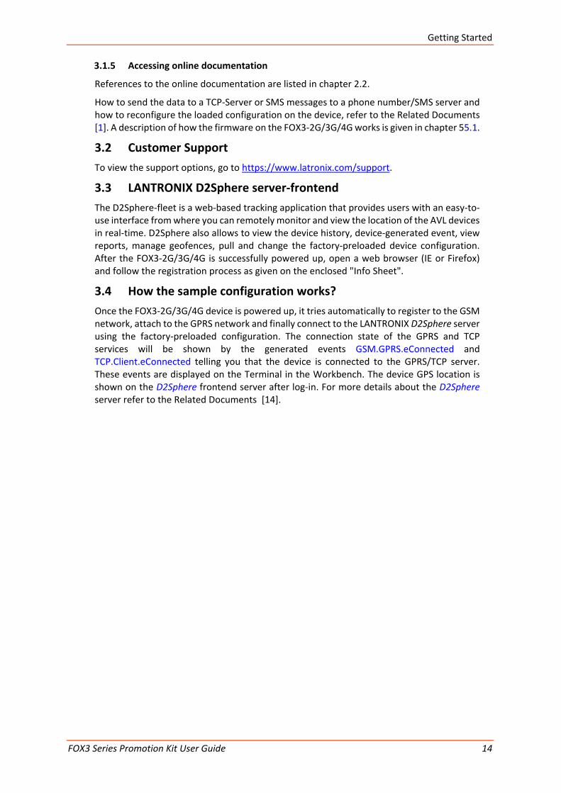
3.1.5 Accessing online documentation
References to the online documentation are listed in chapter 2.2.
How to send the data to a TCP-Server or SMS messages to a phone number/SMS server and how to reconfigure the loaded configuration on the device, refer to the Related Documents [1]. A description of how the firmware on the FOX3-2G/3G/4G works is given in chapter 55.1.
3.2 Customer Support To view the support options, go to https://www.latronix.com/support.
3.3 LANTRONIX D2Sphere server-frontend The D2Sphere-fleet is a web-based tracking application that provides users with an easy-to-use interface from where you can remotely monitor and view the location of the AVL devices in real-time. D2Sphere also allows to view the device history, device-generated event, view reports, manage geofences, pull and change the factory-preloaded device configuration. After the FOX3-2G/3G/4G is successfully powered up, open a web browser (IE or Firefox) and follow the registration process as given on the enclosed "Info Sheet".
3.4 How the sample configuration works? Once the FOX3-2G/3G/4G device is powered up, it tries automatically to register to the GSM network, attach to the GPRS network and finally connect to the LANTRONIX D2Sphere server using the factory-preloaded configuration. The connection state of the GPRS and TCP services will be shown by the generated events GSM.GPRS.eConnected and TCP.Client.eConnected telling you that the device is connected to the GPRS/TCP server. These events are displayed on the Terminal in the Workbench. The device GPS location is shown on the D2Sphere frontend server after log-in. For more details about the D2Sphere server refer to the Related Documents [14].

Control-Box - Hardware Description
FOX3 Series Promotion Kit User Guide 15
4 Control-Box - Hardware Description
This chapter gives you some information about the operation of the control box. It allows you to exercise the function of all inputs and outputs on the FOX3-2G/3G/4G device without the need to add any other external component to them.
The components on the control-box can be identified from the figures below showing the front, top, and the rear panels.
4.1 Front panel overview
Figure 10: Front panel of the control-box.
A description of each of the items on the front panel is provided in Table 4.
Item Description INPUT (12V – 32V) Input power supply for control-box and FOX3-2G/3G/4G device with 1.1 A fuse protected.
Table 4: Front panel overview.
4.2 Top panel overview
Figure 11: Top panel of the control-box.
A description of each of the items on the top panel is provided in Table 5.
Item Description LED (+IN) Lights when the +IN-switch is turned to ON. LED (IGN) Lights when the IGN-switch is turned to ON. +IN - switch This two-way-switch enables or disables power to the connected FOX3-2G/3G/4G unit. (To
enable power to the device, the Current- switch must be set to “ON“) IGN - switch This two-way-switch wakes up the FOX3-2G/3G/4G device from IGN-sleep mode and sets the
IGN-pin of the FOX3-2G/3G/4G to High or Low signal level for using the rising edge and falling edge events.
IO - switches These pins have dual functions. All are controlled by the internal firmware of FOX3-2G/3G/4G. Therefore, the user must define whether to use them as analog or digital pins. The configured digital pins can be inputs or outputs while the analog pins can only be inputs. Their function is controlled with commands with $PFAL,IO0[1,2].Config=DI,1,10 or $PFAL,IO0[1,2].Config=AI,1,10 by changing the electrical behaviour of the reference pin to digital or analogue input (DI = Digital input; AI = Analogue input). These three-way switches (from IO/1 to IO/3) allow operation of the IOs either as digital/analogue inputs or digital outputs. More details how to test these IOs, are given below. Please note that, due to the the PROMOTION-KIT comes with all PREMIUM-FEATURE activated, the IO2 and IO3 are activated for using the "CAN-INTERFACE". Only IO/1 remains

Control-Box - Hardware Description
FOX3 Series Promotion Kit User Guide 16
Item Description free and can be used as general purpose input/output pin. For more details please refer to the Related Documents [2].
Testing IOs as digital inputs:
When the reference IO (e.g: IO/1) is configured as digital input with "$PFAL,IO0.Config=DI,2,10", the FOX3-2G/3G/4G device will generate a rising edge event "IO.e0=redge" and set the state of the IO/1 to high "IO.s0=high", if:
• the position of the IO/1-Switch changes from "Digital IN - Low" to "Digital IN - High". and will generate a falling edge event "IO.e0=fedge" and sets its state to low "IO.s0=low", if:
• the position of the IO/1-Switch changes from "Digital IN - High" to "Digital IN -Low".
Testing IOs as analogue inputs:
When the reference IO (e.g: IO/1) is configured as analogue input with "$PFAL,IO0.Config=AI,2,10, you have to calibrate first this IO the low and high voltages. To do it, perform the following steps (e.g. IO/1):
1. Switch the IO/1-Switch (IO/1) to "Digital IN - Low" position. 2. Send the command “$PFAL,IO0.Calibrate,offset=0" from the Workbench Editor ➒
(see Fig. 8) to FOX3-2G/3G/4G. 3. Switch the IO/1-Switch (IO/1) to "Digital IN - High" position. 4. Send the command “$PFAL,IO0.Calibrate,gain=15" from the Workbench Editor ➒
(see Fig. 8) to FOX3-2G/3G/4G. 5. Switch the IO/1-Switch (IO/1) to "Digital OUT / analogue IN" position. This position
has a fixed voltage of approx. 6V. Now, you can configure an alarm (e.g. $PFAL,CNF.Set,AL31=Sys.Timer.e0&IO.s0>6.0:IO6.Set=high) to switch on an LED (e.g. IO/3) when the voltage on the IO/3 is higher than e.g. 5.0 V. To test it, perform the steps below:
6. Send the configuration "$PFAL,CNF.Set,AL31=Sys.Timer.e0&IO.s2>5.0:IO13.Set=hpulse,5000" from the Workbench Editor ➒ (see Fig. 8) to FOX3-2G/3G/4G.
7. Switch the IO/1-Switch (IO/1) to "Digital OUT / analogue IN" position. 8. Send the command "$PFAL,Sys.Timer0.Start=single,1000" from the Workbench
Editor ➒ (see Fig. 8) to FOX3-2G/3G/4G After the timer expires (1 second has passed), the red LED on the FOX3-2G/3G/4G (front side, next to the 6pin accessory port) goes ON for 5 seconds and then turns OFF. For more details about the LED on the FOX3-2G/3G/4G, refer to the Related Documents [2].
Testing IOs as digital outputs:
When the reference IO (e.g: IO/1) is supposed to be used as digital output, there is no configuration to be done in the firmware. To test it, perform the steps below:
1. Remove the available configuration for the IO/1 with "$PFAL,IO0.Config=" 2. Switch the IO/1-Switch to the "Digital OUT / analogue IN" position 3. Send the command "$PFAL,IO4.Set=high" to set it to High 4. Send the command "$PFAL,IO5.Set=low" to set it to Low
Table 5: Components on the top panel of the control-box and their functionality
4.3 Rear panel overview
Figure 12: Rear panel of the control-box.
A description of each of the items on the rear panel is provided in Table 6.
Item Description Serial port 0 Via your own RS-232 cable you can connect the PROMOTION-KIT to a PC and evaluate the connected
FOX3-2G/3G/4G device.

Explanation of the Sample Configuration
FOX3 Series Promotion Kit User Guide 17
5 Explanation of the Sample Configuration
In the table below you find a detailed description of the configuration preloaded in the device shipped with promotion kit. To call this configuration use either the command $PFAL,Cnf.Show or use the button “Read current device configuration” from the Editor of the Workbench software. See chapter 3.1.4, Fig. 9.
Functions Configuration alarms and their descriptions.
Tracking $PFAL,CNF.Set,AL0=SYS.Device.eStart:SYS.TIMER1.start=cyclic,20000&SYS.TIMER0.start=cyclic,5000&SYS.TIMER2.start=cyclic,2000
AL0: Every time the FOX3 turns on or wakes up, it starts three cyclic Timers: Timer0, Timer1 and Timer2 with repeat timer events that occur every time a 20000, 5000 and 2000 of milliseconds elapses. These timer events will be used later in other alarms to start or stop actions (PFAL commands). E.g. Timer0 event (Sys.Timer.e0) is used in AL9 to save GPS position data every 20 sec. in the history if other set conditions (like: displaced distance is > 50m and GPS fix is valid) are true.
$PFAL,CNF.Set,AL1=SYS.Device.eStart:GPS.Nav.Position0=load0&GPS.Nav.Position1=load0&Sys.Timer3.Start=single,10000
AL1: Every time the FOX3 turns on or wakes up, it loads the saved Position from memory slot zero to GPS.Nav.Position0 and starts a Timer3 with a single timer event that occurs once, after 100000 of milliseconds (10 sec.).
$PFAL,CNF.Set,AL2=SYS.Device.eShutdown:GPS.Nav.Position0=save0&GPS.Nav.SaveLastValid
AL2: Before the device goes in sleep mode, it saves both its position from GPS.Nav.Position0 to memory slot zero and the last valid position in the corresponding configuration parameter.
$PFAL,CNF.Set,AL3=SYS.Device.eShutdown:TCP.Client.Send,8,"<sfal.event text='shutdown'>"
AL3: Before the device goes in sleep mode, it sends a TCP packet to the server including the RMC GPS protocol and the user text <sfal.event text='shutdown'>, telling the server D2Sphere its current location with the text event ‘shutdown’.
$PFAL,CNF.Set,AL9=Sys.Timer.e0&GPS.Nav.Position.s1>50&GPS.Nav.sFix=correct&GPS.Nav.sSpeed>2:GPS.Nav.Position1=current&GPS.History.Write,0,""
AL9: Each time the cyclic Timer0 runs out, the displaced distance from the position 1 is greater than 50 meters, the GPS is corrected and the speed is > 2m/s, then the device sets the new position to current position and saves the position in the history (Data logging) inside the device.
$PFAL,CNF.Set,AL10=Sys.Timer.e1&GPS.Nav.Position.s0>200&GPS.Nav.sSpeed>2:GPS.Nav.Position0=current&TCP.Client.Send,8,"<sfal.pos>"
AL10: Each time the cyclic Timer1 runs out, the displaced distance is greater than 200 meters, the GPS is corrected and the speed is > 2m/s, then the device sets the new position to current position and sends a TCP packet to the server including the GPRMC protocol and the user text <sfal.pos>.
$PFAL,CNF.Set,AL11=GPS.Nav.eChangeHeading&GPS.Nav.sSpeed>2:GPS.Nav.Position1=current&GPS.Nav.Position0=current&GPS.History.Write,0,"HEAD"
AL11: Each time the predefined angle (course) is exceeded and the speed is > 2m/s, then the device sets the new position to current position AND it saves the position in the History (Data logging) with the user text "HEAD"
$PFAL,CNF.Set,AL12=GPS.Nav.eChangeHeading&GPS.Nav.sSpeed>2:TCP.Client.Send,8,"<sfal.pos>"

Explanation of the Sample Configuration
FOX3 Series Promotion Kit User Guide 18
Functions Configuration alarms and their descriptions.
AL12: Each time the predefined angle (course) is exceeded and the speed is > 2m/s, then the device sends a TCP packet to the server including the GPRMC protocol AND the user text ‘HEAD’.
$PFAL,CNF.Set,AL13=IO.e8=redge:Sys.Timer3.Start=single,2000&Sys.Timer4.Stop
AL13: Each time the Ignition is turned ON (IO.e8=redge), the device starts Timer3 with a single timer event that occurs once, after 2000 of milliseconds (2 sec.) and stops running the Timer4.
$PFAL,CNF.Set,AL14=Sys.Timer.e3&IO.s8=high:TCP.Client.Send,8,"<sfal.trip.start>"&GPS.History.Write,20,"<sfal.trip.start>"&GPS.Nav.Distance=0
AL14: When the single Timer3 runs out and the status of the Ignition is still high, then the device sends a TCP packet to the server including the GPRMC protocol, the user text <sfal.trip.start> and also it saves the user text in the history (data logging) with the user text <sfal.trip.start>.
$PFAL,CNF.Set,AL15=IO.e8=fedge:Sys.Timer4.Start=Single,2000&Sys.Timer3.Stop
AL15: When the Ignition is turned OFF (IO.e8=fedge), the device starts Timer4 with a single timer event that occurs once, after 2000 of milliseconds (2 sec.) and stops running the Timer3.
$PFAL,CNF.Set,AL16=Sys.Timer.e4&IO.s8=low:TCP.Client.Send,8,"<sfal.trip.stop dist='&(NavDist)'>"&GPS.History.Write,20,"<sfal.trip.stop dist='&(NavDist)'>"&Sys.Timer5.Start=single,60000
AL16: When the Timer4 runs out and the Ignition pin is still OFF, then the device sends a TCP packet to the server including the GPRMC protocol, the user text <sfal.trip.stop> and the driven distance in meters &(NavDist). It also saves the user text in the history (data logging) with the user text <sfal.trip.stop>, the driven distance in meters and starts Timer5 with a single timer event that occurs once, after 60000 of milliseconds (60 sec.). //If another unit of the driven distance is needed, then replace &(NavDist) with the corresponding dynamic variable: &(NavDist.km) or &(NavDist.miles)
$PFAL,CNF.Set,AL17=Sys.Timer.e5&IO.s8=low:Sys.Device.Sleep=IGN
AL17: When the Timer5 runs out and the status of the Ignition pin is still low, then the device goes in sleep mode with the wakeup parameter IGN. The wakeup parameter ‘IGN’ means, the device will wake up whenever the Ignition pin is switched to high.
LED status $PFAL,CNF.Set,AL4=SYS.Power.eDropped:IO13.Set=cyclic,200,200
AL4: When the external/main power drops and the FOX3 runs on its internal backup battery, the red LED (IO13) starts flashing 200msON/200ms OFF.
$PFAL,CNF.Set,AL5=SYS.Power.eDetected:IO13.Set=high
AL5: When the external/main power is applied and the FOX3 runs on its internal backup battery, the red LED (IO13) gets solid.
$PFAL,CNF.Set,AL6=Sys.Device.eStart&Sys.Power.sVoltage>=9:IO13.Set=high
AL6: When the FOX3 turns on or wakes up from Sleep and external/main power is applied, the red LED (IO13) gets solid.
$PFAL,CNF.Set,AL7=Sys.Device.eStart&Sys.Power.sVoltage<9:IO13.Set=cyclic,200,200
AL7: When the FOX3 turns on or wakes up on its internal backup battery and the external power is below 9VDC, the red LED (IO13) starts flashing 200msON/200msOFF.
$PFAL,CNF.Set,AL8=TCP.Client.ePacketSent:IO12.Set=lpulse,200
AL8: Each time the FOX3 sends a TCP message to the server, the green LED (IO12) initiates a low pulse of 200ms.
$PFAL,CNF.Set,AL18=Sys.device.eStart&GPS.Nav.sFix=invalid:IO11.Set=cyclic,200,200
$PFAL,CNF.Set,AL19=GPS.Nav.eFix=valid:IO11.Set=high
$PFAL,CNF.Set,AL20=GPS.Nav.eFix=invalid:IO11.Set=cyclic,200,200

Explanation of the Sample Configuration
FOX3 Series Promotion Kit User Guide 19
Functions Configuration alarms and their descriptions.
$PFAL,CNF.Set,AL27=Sys.device.eStart&GPS.Nav.sFix=valid:IO11.Set=high
AL18, 19, 20, 27: Every time the FOX3 turns on or wakes up, it checks all the time for GPS fix and sets the orange LED (IO11) either blinking (AL19, AL27) or turns it ON (AL18, AL27) depending if the device has a GPS fix (AL19, AL27) or not (AL18, AL20).
$PFAL,CNF.Set,AL21=GSM.eOpfound:IO12.Set=cyclic,200,200
$PFAL,CNF.Set,AL26=GSM.eOplost:IO12.Set=low
AL21, 26: Once the device has found a GSM operator, the green LED (IO12) will blink and when it has lost a GSM operator, the LED will turn OFF.
$PFAL,CNF.Set,AL22=GSM.GPRS.eConnected:IO12.Set=cyclic,400,400
$PFAL,CNF.Set,AL25=GSM.GPRS.eDisconnected&GSM.sOpValid:IO12.Set=cyclic,200,200
AL22, 25: Once the device is attached to GPRS services, the green LED (IO12) will blink and when it is detached from that services but it still has a valid GSM operator, the green LED (IO12) will blink fast.
$PFAL,CNF.Set,AL23=TCP.Client.eConnected:IO12.Set=high
$PFAL,CNF.Set,AL24=TCP.Client.eDisconnected&GSM.sOpValid:IO12.Set=cyclic,400,400
AL23, 24: Once the device is connected to TCP server, the green LED (IO12) goes ON and when it is disconnects from that server but it still has a valid GSM operator, the green LED (IO12) will blink slower than when it detaches from GPRS services.
Configuration parameters $PFAL,CNF.Set,DEVICE.BAT.CHARGEMODE=eco
Starts charging if the voltage of the internal battery drops to less than 3.9V and terminates charging when the battery is full-charged.
$PFAL,CNF.Set,DEVICE.BAT.MODE=auto
Automatically switching between external power and internal battery power source depending on the power source currently available. External DC power supply has priority, if it is higher than 8 V.
$PFAL,CNF.Set,DEVICE.COMM.SERIAL0=cmd,7F
The serial port 0 is set into the command operation mode with protocols and events output enabled.
$PFAL,CNF.Set,DEVICE.COMM.TCP.CLIENT=cmd,60
The serial port 0 is set into the command operation mode without protocols and events output enabled
$PFAL,CNF.Set,DEVICE.GPS.AUTOCORRECT=on,5.0,58,50,10,50
Enables filtering of GPS auto correction to calculate a valid GPS fix using maximal allowed PDO of 5.0, maximal speed limit of 58 m/s, maximal allowed distance error of 50, drop count incorrect position of 10 and maximal acceleration of 50 m/s.
$PFAL,CNF.Set,DEVICE.GPS.CFG=4
At least 4 satellites must be in use to consider a GPS fix as valid.
$PFAL,CNF.Set,DEVICE.GPS.HEADING=25
Heading tolerance is set to 25 degrees. Each time this angle is exceeded, the event GPS.Nav.eChangeHeading occurs, and the driving direction resets to zero.
$PFAL,CNF.Set,DEVICE.GPS.TIMEOUT=1,30
Restarts the GPS receiver to do a new search for visible GPS satellites, if within this time no valid fix is available.
$PFAL,CNF.Set,DEVICE.NAME=FOX3
Device name is defined to FOX3

Explanation of the Sample Configuration
FOX3 Series Promotion Kit User Guide 20
Functions Configuration alarms and their descriptions.
$PFAL,CNF.Set,DEVICE.PFAL.SEND.FORMAT="$",CKSUM,"","$<end>"
The syntax of the PFAL messages is defined to start each line with the character ‘$’, followed by the user text and terminated by a NMEA compatible checksum and <CRLF>. The complete message(s) end(s) with $<end>. These settings can be changed based on your server requirements.
$PFAL,CNF.Set,PPP.PASSWORD=blau
Required string (password) for the Chap and Pap authentication methods over PPPP to attach the device into the GPRS network. This setting is provider-dependant.
$PFAL,CNF.Set,PPP.USERNAME=blau
Required string (username) for the Chap and Pap authentication methods over PPPP to attach the device into the GPRS network. This setting is provider-dependant.
$PFAL,CNF.Set,GPRS.APN=Public4.m2minternet.com
APN (Access Point Name) name that your network operator has provided to you to connect the device to the GPRS/Internet. This setting is operator or provider dependant.
$PFAL,CNF.Set,GPRS.AUTOSTART=1
Enables automatic attachments to the GPRS network. If the GPRS network connection gets lost, it tries to reconnect automatically as soon as the network is available again.
$PFAL,CNF.Set,GPRS.DIAL=ATD*99***1#
The V.250 'D' (Dial) command causes the device to enter the V.250 online data state.
$PFAL,CNF.Set,GPRS.QOS=0,0,0,0,0
Quality of Service Profile used when the device sends an Activate PDP Context Request message to the GPRS network.
$PFAL,CNF.Set,GPRS.QOSMIN=0,0,0,0,0
Minimum acceptable profile checked by the device against the negotiated profile returned in the Activate PDP Context Accept message.
$PFAL,CNF.Set,GPRS.TIMEOUT=1,600000
Detaches the device from GPRS network if no TCP communication available within the timeout.
$PFAL,CNF.Set,GSM.BALANCE.DIAL=*100#
GSM dial number for retrieving balance information
$PFAL,CNF.Set,GSM.OPLOST.RESTART=1,1200000,8
Reinitializes the GSM engine periodically until a GSM operator is found.
$PFAL,CNF.Set,PROT.3DP=0
3DP protocol (motion sensor data) is deactivated
$PFAL,CNF.Set,PROT.AREA=0
AREA protocol (area states) is deactivated
$PFAL,CNF.Set,PROT.BIN=0
BIN protocol (FALCOM) is deactivated
$PFAL,CNF.Set,PROT.GGA=0
GGA protocol is deactivated
$PFAL,CNF.Set,PROT.GLL=0
GLL protocol is deactivated

Explanation of the Sample Configuration
FOX3 Series Promotion Kit User Guide 21
Functions Configuration alarms and their descriptions.
$PFAL,CNF.Set,PROT.GSA=0
GSA protocol is deactivated
$PFAL,CNF.Set,PROT.GSM=1
GSM protocol is activated
$PFAL,CNF.Set,PROT.GSV=0
GSV protocol is deactivated
$PFAL,CNF.Set,PROT.IOP=1
IOP protocol is activated
$PFAL,CNF.Set,PROT.RMC=1
RMC protocol is activated
$PFAL,CNF.Set,PROT.START.BIN=$!
BIN protocol starts with ‘$!’.
$PFAL,CNF.Set,PROT.VTG=0
VTG protocol is deactivated
$PFAL,CNF.Set,TCP.CLIENT.CONNECT=1,5.35.253.3,4444
Enables the connection to the remote server and specifies the IP address and the Port number of the TCP server to connect to.
$PFAL,CNF.Set,TCP.CLIENT.DNS.TIMEOUT=86400
The length of time (in seconds) to keep the DNS cache valid.
$PFAL,CNF.Set,TCP.CLIENT.LOGIN=1
Sends the login data automatically to the remote server after requesting the TCP server for establishing a connection.
$PFAL,CNF.Set,TCP.CLIENT.PING=1,240000
Activates sending of pings and specifies the amount of time, in milliseconds, on which a ping will be sent to the remote server.
$PFAL,CNF.Set,TCP.CLIENT.SENDMODE=2
Safe and non-volatile transmission mode.
$PFAL,CNF.Set,TCP.CLIENT.TIMEOUT=300000,30000
Period of time in milliseconds that the device will wait for a response and between two connection attempts when TCP connection fails.
$PFAL,CNF.Set,GSM.PIN=1111
Enters/saves the PIN code of the SIM card inserted into the device..
$PFAL,GSM.Band=auto
The GSM band to be used by the device is set to ‘auto’. The device registers to that frequency band currently available. Refer to the PFAL command set for the supported settings.
Factory settings It consists of configuration settings preloaded at the factory during the manufacturing of FOX3 series devices. The user has the possibility of personalizing this configuration and with the help of $PFAL,Sys.Device.FactoryReset command it is possible to overwrite the User Settings with the Factory Settings. After reseting the device to factory settings, the device must be configured in order to operate referring to your application (see chapter for more details
Add-ons* The Promotion Kit is shipped with some sample functions. To extend its functionality, you can refer to the setting file „AddOns.conf“ and modify it according to your needs. Please contact support (see chapter 3.2) for more details about the file „AddOns.conf“.

Explanation of the Sample Configuration
FOX3 Series Promotion Kit User Guide 22
Functions Configuration alarms and their descriptions.
eCodrive (This feature includes instant and results for driving activities and driver behaviors such as: TripStart / TripStop / Harsh-Brake / Harsh-Acceleration / Harsh-Turn) - refer to the Related documents [6]
Tampering Detection of GPS antenna (unplugged / plugged / cut) – Refer to the PFAL command set manual.
Waypoints (define reference GPS points along a specific route where the vehicle should track. Alerts when exiting/entering that route)
Tilting (> 45°) and crash detection (1 x Tilt alert every 15 sec.)
1Wire (iButton + Temp. Sensors)
Supported iButton: DS1402D-DR8+ Blue Dot Receptor iButton Reader Cable with DS1982 iButton and DS1921 iButton (MAXIM).
Supported 1Wire Temp.Sensor: DS18(B)20 (MAXIM). Refer to the Related documents [13]
CAN-OBDII (read out some of the supported OBDII raw values). Refer to the Related documents [4]
CAN-FMS (read out some of the supported FMS parameters). Refer to the Related documents [4]
HINT: The user text (in quotation marks “ ”) started with “sfal” indicates an event on our D2Sphere serve. This event text is only supported on our server, use other text formats for your own server.
Appendix
FOX3 Series Promotion Kit User Guide 23
6 Appendix
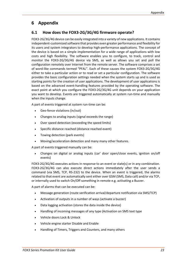
6.1 How does the FOX3-2G/3G/4G firmware operate? FOX3-2G/3G/4G device can be easily integrated into a variety of new applications. It contains independent-customized software that provides even greater performance and flexibility for its users and system integrators to develop high-performance applications. The concept of the device is based on a simple implementation for a wide range of applications with low costs and high flexibility. The software enables you to configure, to track, control and monitor the FOX3-2G/3G/4G device via SMS, as well as allows you set and poll the configuration remotely over Internet from the remote server. The software comprises a set of word-like commands termed “PFAL”. Each of these causes the system FOX3-2G/3G/4G either to take a particular action or to read or set a particular configuration. The software provides the basic configuration settings needed when the system starts up and is used as starting points for the creation of user applications. The development of user applications is based on the advanced event-handling features provided by the operating software. The exact point at which you configure the FOX3-2G/3G/4G unit depends on your application you want to develop. Events are triggered automatically at system run-time and manually when the inputs change.
A part of events triggered at system run-time can be:
• Geo-fence violations (in/out)
• Changes to analog inputs (signal exceeds the range)
• Over speed detection (exceeding the speed limits)
• Specific distance reached (distance reached event)
• Towing detection (park events)
• Moving/acceleration detection and many many other features.
A part of events triggered manually can be:
• Changes on digital or analog inputs (car' door open/close events, ignition on/off events)
FOX3-2G/3G/4G executes actions in response to an event or state(s) or in any combination. FOX3-2G/3G/4G can also execute direct actions immediately after the user sends a command (via SMS, TCP, RS-232) to the device. When an event is triggered, the alarms related to that event are automatically sent either over GSM (SMS, Data call) and/or via TCP, or internally used to switch On/Off something in remote e.g. activating a Buzzer.
A part of alarms that can be executed can be:
• Message generation (route verification arrival/departure notification via SMS/TCP)
• Activation of outputs in a number of ways (activate a buzzer)
• Data logging activation (stores the data inside the device)
• Handling of incoming messages of any type (Activation on SMS text type
• Vehicle doors Lock & Unlock
• Vehicle engine starter Disable and Enable
• Handling of Timers, Triggers and Counters, and many others

Appendix
FOX3 Series Promotion Kit User Guide 24
Above are listed just a few software features and for a full view of the set of events, states, alarms, configurations and their functionalities refer to the Related Documents [1].
6.2 Installation cables (CA27 & CA31 & CA69 & CA76 & CA123) There are two installation cables (CA31 and CA69) included in the PROMOTION-KIT. The CA31 is used to install your FOX3-2G/3G/4G device in a vehicle and additionally to interface Lantronix RFID reader or 3rd party products with RS-232 interface via the 4-pin UCOM connector. This cable has an 8pin double row connector that connects to the FOX3-2G/3G/4G and a 4pin double row connector that connects to one of the LANTRONIX accessories or 3rd party products.
The CA69 is used to test 1-wire interface using your own 1-wire temperature sensors and 3rd party products with RS-232 interface via the 4-pin UCOM connector. Table 7 and Table 8 provide a reference to the colour codes of these cables. More details about the in-vehicle installation refer to the Related Documents [11].
Note: When connecting the CA31 to the vehicle wiring, for safety reason firstly connect the ground pin to the negative pole of the vehicle battery and then the +IN pin to the positive pole. When using a switch between FOX3-2G/3G/4G and external power source, first turn OFF the switch during the installation and then turn ON after completing the installation.
The CA27 is used as service cable, which connects to the 8pin main port of one of the FOX3-2G/3G/4G series device, your PC/Laptop COM port and to the cigarette lighter socket of a vehicle to apply power to the device. To (re)configure the device install the Workbench software.
The CA76 is used as service cable if the 8pin main port or 1st serial port of one of the FOX3-2G/3G/4G series device can’t be accessed. It connects to the 6pin accessory port and your PC/Laptop COM port. To (re)configure the device install the Workbench software.
The CA123 is used to connect the device to the CAN OBDII connector of your vehicle and apply power to the device from this OBDII connector.This cable has also a separate wire which needs to be connected to the ignition sense of your vehicle for using the Ignition-Sleep mode and trip starts and stops.
Figure 13: Supplied cables (for colors and pinout see Table 7 and Table 8)
The pin function and the colour codes of the CA31 is listed in table below:

Appendix
FOX3 Series Promotion Kit User Guide 25
COLOUR NAME DIRECTION DESCRIPTION LEVEL
Open-end wires
RED +IN Input Power supply input. V+IN = + 10.8 ... + 32.0 V Imax ≤ 1.5 A
BROWN GND - Ground. 0 V
BLUE IGN Input It can be connected to the vehicle ignition
d for trip START and STOP reports and IGN- mode.
HIGH ≥+10.8 .. +32.0 V DC; LOW
ORANGE I/O1 Input/Output
Software configurable pins. They can e either as input or output. They have dual ns as analog or digital inputs.
OUT: 100 mA max. @ +0 .. DC
YELLOW I/O2 Input/Output IN: 0 V..+32.0V DC (High & Low free-
mmable)
GREEN I/O3 Input/Output Analog : < 32.0 V / 10 bits on
PURPLE RxA_0 Input Serial Port 0 - Receive data V24, ±12 V
BLACK TxA_0 Output Serial Port 0 - Transmit data V24, ±12 V
4pin UCOM Connector
PURPLE RxA_0 Input Serial Port 0 - Receive data V24, ±12 V
BLACK TxA_0 Output Serial Port 0 - Transmit data V24, ±12 V
RED +IN Input Power supply input. =+IN
BROWN GND - Ground. 0V
Table 7: PIN function of the CA31 cable
The pin function and the colour codes of the CA69 is listed in table below:
COLOUR NAME DIRECTION DESCRIPTION LEVEL
Open end wires
PINK 1-Wire Input /Output 1-Wire master interface for Driver ID, temperature and humidity sensors. VOUT = + 2.8 .. +5.0 V
BROWN GND - Ground Reference. 0 V
PURPLE RxA_1 Input Serial Port 1 - Receive data. V24, ±12 V
BLACK TxA_1 Output Serial Port 1- Transmit data V24, ±12 V
YELLOW SCL Output I2C bus interface - Serial Clock line -
GREEN SDA Input /Output I2C bus interface - Serial Data line -
4pin UCOM Connector
PURPLE RxA_1 Input Serial Port 1 - Receive data V24, ±12 V
BLACK TxA_1 Output Serial Port 1- Transmit data V24, ±12 V
RED +IN Input Power supply input. V+IN = + 10.8 ... + 32.0 V Imax ≤ 1.5 A
BROWN GND - Ground. 0V
Table 8: Pinout of the CA69 cable

Appendix
FOX3 Series Promotion Kit User Guide 26
The pinout of this cable CA76 is listed in table below:
2x3 MICROFIT DB9 female Description
RX RX Receive data TX TX Transmit data GND GND Ground
Table 9: Pinout of the CA76 cable
The pinout of this cable CA123 (OBDII 4Pin Cable) is listed in table below:
2x4 MICROFIT OBDII connector Description
2 5 GND 6 6 CAN_High 5 14 CAN_Low
1 16 V+
3 NC IGN as separate wire
Table 10: Pinout of the CA123 cable
6.3 Installing your own SIM card and replacing the internal battery
To insert your own SIM card into the FOX3-2G/3G/4G' SIM holder and replace the internal battery by a new one, follow the steps represented in figure below:
Figure 14: Inserting you SIM card and replacing the battery by a new one
For more details refer to the Related Documents [2].

Appendix
FOX3 Series Promotion Kit User Guide 27
When using your own SIM card and another TCP server, the following table shows the basic configuration settings that should be done in the FOX3 device to register the device in the GSM network and enable internet connection to your TCP-Server. These configuration settings should be done locally via serial port connection. After inserting your SIM card and powering up the device, send the following commands (marked in red) from Workbench Editor ➒ (see Fig. 8) to the FOX3-2G/3G/4G.
SETUP
$PFAL,Cnf.Set,GPRS.APN=internet.t-d1.de (enter your provider's APN) $PFAL,Cnf.Set,GPRS.QOS=3,4,3,0,0 $PFAL,Cnf.Set,GPRS.QOSMIN=0,0,0,0,0 $PFAL,Cnf.Set,PPP.USERNAME=t-d1 (if your provider requires) $PFAL,Cnf.Set,PPP.PASSWORD=gprs (if your provider requires) Settings required for a GPRS attachment
SETUP
$PFAL,Cnf.Set,TCP.CLIENT.CONNECT=1,2222.222.222.222,1111 (enter your IP and Port) Settings required for a TCP connection.
Where: 2222.222.222.222 - is the IP-address of the TCP server to be connected; 1111 - is the TCP port number of the TCP server to be connected; $PFAL,CNF.Set,TCP.CLIENT.LOGIN=1 Sends the login data automatically to the remote server after requesting the TCP server for establishing a connection.
SETUP $PFAL,Cnf.Set,GPRS.AUTOSTART=1 (default = 0) Activate GPRS autostart to reconnect automatically when GPRS network connection gets lost.
SETUP $PFAL,Cnf.Set,DEVICE.PIN=1111 (enter the PIN of the used SIM card) Enter the SIM PIN to register the FOX3 device into the GSM network:
Where: 1111 - is the PIN of the inserted SIM card.
Table 11: Adapt device configuration settings to your application conditions (mandatory settings).
FOX3-2G/3G/4G/-4G LOGIN DATA TO YOUR SERVER
After establishing TCP connection with your remote server, the following ServerLogin data is automatically sent to your remote server. For more details refer to the Related Documents [1]. $<MSG.Info.ServerLogin> $DeviceName=FOX3 $Security=0 $Software=avl_2.13.0 (BxBGT1gzIHJldjowMy1OVUNIAgEA) $Hardware=FOX3 rev:03-NUCH $LastValidPosition=$GPRMC,143445.000,A,5040.4096,N,01058.8542,E,0.01,0.00,040315,, $IMEI=353816054739497 $PhoneNumber=+491734567124564 $LocalIP=10.208.151.168 $CmdVersion=2 $SUCCESS $<end>
Table 12: Login data sent automatically from the FOX3-2G/3G/4G to your remote server when the device starts up.