Foreword - C.R. England ... Volvo,US10EmissionsSolution ......
456
Transcript of Foreword - C.R. England ... Volvo,US10EmissionsSolution ......

ForewordThis manual contains information concerning the operation andfunction of the Volvo Link System. The information in this manualapplies to vehicles built January 2010 and later. Please keep this manualin the vehicle at all times.
Note: Illustrations in this manual are used for reference only and maydiffer slightly from the actual vehicle. However, key componentsaddressed in this document are represented as accurately as possible.
The National Highway Traffic Safety Administration (NHTSA) andVolvo Trucks North America should be informed immediately if youbelieve that the vehicle has a defect that could cause a crash, injuryor death.
Contact NHTSA by calling the Auto Safety Hotline at 1 (888)327-4236, by writing to NHTSA, U.S. Department of Transportation,Washington, DC 20590, by TTY at 1 (800) 424-9153, or visit theirwebsite at www.nhtsa.dot.gov.
Volvo Trucks North America, a division ofVolvo Group North America, Inc.
Greensboro, NC USA
Order number: PV776-21232734
©2010 Volvo Group North America, Inc., Greensboro, NC USA
All rights reserved. No part of this publication may be reproduced,stored in retrieval system, or transmitted in any forms by any means,electronic, mechanical, photocopying, recording or otherwise, withoutthe prior written permission of Volvo Trucks North America, a divisionof Volvo Group North America, Inc.
ContentsINTRODUCTION............................................................................................................1
.......................................................................................................................................1ADVISORY LABEL DEFINITIONS (IN HANDBOOK)........................................1INFORMATION FOR THE OWNER.......................................................................2EMISSIONS CONTROL COMPLIANCE................................................................5Exhaust and Noise Emissions ....................................................................................5B5 Approval For Volvo US 10 Certified Products.....................................................6ENGINES OTHER THAN VOLVO: ........................................................................8VEHICLE DATA.....................................................................................................13Identification and Labels..........................................................................................13SERVICE LITERATURE........................................................................................19SERVICE ASSISTANCE ........................................................................................20REPORTING SAFETY DEFECTS.........................................................................21United States ...........................................................................................................21Canada......................................................................................................................21Mexico .....................................................................................................................21EVENT DATA RECORDING DEVICES...............................................................22
SAFETY INFORMATION ...........................................................................................23GENERAL SAFETY INFORMATION ......................................................................23Operating the Vehicle...............................................................................................23Operating in Bobtail Mode ......................................................................................24VORAD® COLLISION WARNING SYSTEM .....................................................26ADVISORY LABELS.............................................................................................27CAB ENTRY AND EXIT .......................................................................................28General.....................................................................................................................28General Entry Guidelines.........................................................................................31Driver Side Entry/Exit .............................................................................................33ENTERING SLEEPER FROM SEAT.....................................................................38Standard Gear Lever ................................................................................................38SAFETY EQUIPMENT ..........................................................................................40Warning Triangles, Day Cab....................................................................................41Sleeper Cab ..............................................................................................................42SAFETY BELT SYSTEM.......................................................................................43SRS AIRBAG..........................................................................................................44SRS System..............................................................................................................44
INSTRUMENTS AND CONTROLS ...........................................................................52CAB INTERIOR..........................................................................................................52INSTRUMENT PANEL ..............................................................................................53Tell-Tales..................................................................................................................53Colors.......................................................................................................................53Panel Arrangement...................................................................................................54INSTRUMENT PANEL GAUGE LAYOUT ..........................................................55Panel A.....................................................................................................................56Panel B.....................................................................................................................57Panel C ....................................................................................................................59
Panel D.....................................................................................................................60Panel E .....................................................................................................................61Tachometer...............................................................................................................64Upper Tell-Tales.......................................................................................................64Speedometer.............................................................................................................64Front and Rear Brake System Air Pressure Gauges ................................................64Oil Pressure Gauge ..................................................................................................65Coolant Temperature Gauge ....................................................................................67Middle and Lower Tell-Tales...................................................................................67Driver Information Display (DID)...........................................................................67Fuel Level Gauge.....................................................................................................67Intake Manifold Pressure Gauge (High Level Cluster Only) ..................................68Application Air Pressure Gauge (High Level Cluster Only) ...................................68Exhaust Pyrometer Gauge (High Level Cluster Only) ............................................69Exhaust Pyrometer Gauge (High Level Cluster Only) ............................................69DASH SWITCHES..................................................................................................91Power Take-Off (PTO).............................................................................................91CLIMATE CONTROL SYSTEMS .........................................................................98AIR CONDITIONING MANUAL CLIMATE CONTROL (MCC) .....................102SLEEPER CLIMATE UNIT..................................................................................106LIGHT CONTROL PANEL ..................................................................................107SLEEPER CONTROL PANEL (SLEEPER MODELS ONLY) ...........................110Sleeper Control Panel, High ..................................................................................112Sleeper Control Panel, Basic..................................................................................114MISCELLANEOUS CAB EQUIPMENT.............................................................122STEERING COLUMN..........................................................................................125ADJUSTABLE STEERING COLUMN................................................................127STEERING WHEEL CONTROLS .......................................................................128MISCELLANEOUS SWITCHES .........................................................................129INTERIOR LIGHTS..............................................................................................130Fresh Air Vent ........................................................................................................134CAB VENTILATION, SLEEPER.........................................................................135Inverter Switch 12 V DC to 120 V AC..................................................................140PARKING HEATER (OPTIONAL, SLEEPER MODELS ONLY) ......................149ANTENNAS..........................................................................................................151TELEVISION ........................................................................................................153TV Antenna............................................................................................................154COMMUNICATION EQUIPMENT.....................................................................155CB Radio................................................................................................................155STORAGE COMPARTMENTS............................................................................156SLEEPER BUNKS ................................................................................................169VN 780, VNL 730, VN 670 OFFICE....................................................................184SLEEPER COMPARTMENT SINK .....................................................................186
OPERATION................................................................................................................192PRE-TRIP INSPECTION AND DAILY MAINTENANCE.....................................192Pre-Trip Assistance ...............................................................................................192
Pre-Trip Inspection Quick List ..............................................................................199New Vehicle Break-In............................................................................................211HOOD OPERATION.............................................................................................213SAFETY BELTS....................................................................................................230Safety Restraint VN 430, VN 630, VN 670 ..........................................................238SEATS, GENERAL ...............................................................................................251NATIONAL STANDARD SEAT ..........................................................................252NATIONAL COMFORT SEAT.............................................................................253PASSENGER SEATS ............................................................................................255ENGINE OPERATION .........................................................................................259IMMOBILIZER FEATURE ..................................................................................260CONTROL AWARENESS FEATURE .................................................................262FUEL ECONOMY DRIVING ..............................................................................263CRUISE CONTROL .............................................................................................270Volvo Engine Brake (I-VEB).................................................................................272BRAKE OPERATION...........................................................................................273Parking Brake/Trailer Supply Valves.....................................................................282Trailer Brake Hand Control ...................................................................................288ANTI-LOCK BRAKING SYSTEM (ABS) ..........................................................290VOLVO ENHANCED STABILITY TECHNOLOGY .........................................292TRACTION CONTROL SYSTEM (TCS) (OPTIONAL) ....................................292Tire Pressure System (If Equipped) .......................................................................294Air Pressure Monitoring and Alert ........................................................................295Tire Temperature Monitoring and Alert.................................................................296VEHICLE SPEED RETARDING DEVICES .......................................................297STARTING THE ENGINE....................................................................................298COLD WEATHER OPERATION .........................................................................306FIFTH WHEEL INSTRUCTIONS........................................................................313Operating the Fifth Wheel Slider...........................................................................332PERFORMANCE BONUS FEATURE.................................................................336Performance Bonus Guide .....................................................................................338AXLES...................................................................................................................342
Volvo, US10 Emissions Solution .................................................................................345Exhaust Aftertreatment System .................................................................................345Safety Information .................................................................................................346Exhaust Aftertreatment System Components and Operation ................................347Selective Catalytic Reduction (SCR) ....................................................................347Diesel Exhaust Fluid (DEF)...................................................................................351Aftertreatment Diesel Particulate Filter (DPF) ......................................................354Aftertreatment Control Module (ACM).................................................................356Exhaust Aftertreatment System Operation ............................................................357Exhaust Aftertreatment System (ATS) Status........................................................367Driver Warnings and On Board Diagnostics (OBD) .............................................370On Board Diagnostics (OBD)................................................................................370Instrument Cluster..................................................................................................370Malfunction Indicator Lamp (MIL) .......................................................................372

Aftertreatment DEF Tank Level - Driver Warning & Inducement ........................373Aftertreatment DEF Quality - Driver Warning & Inducement ..............................374Misfilling Diesel or Aftertreatment DEF Tanks.....................................................375SCR Tampering - Driver Warning & Inducement .................................................376Warranty and Maintenance ....................................................................................377Exhaust Aftertreatment System Maintenance........................................................377Emissions Maintenance .........................................................................................377Engine Maintenance Intervals................................................................................378Engine Gaseous Emission Control Systems ..........................................................379Emissions Control System Warranty .....................................................................380Engine Gaseous Emissions Control System Warranty ..........................................381Federal Emission Requirements ............................................................................381Emission Control System Warranty — California.................................................382Emissions Control System Warranty .....................................................................385Oil Change Intervals ..............................................................................................387
MAINTENANCE AND LUBRICATION..................................................................388DAILY MAINTENANCE .........................................................................................388TOWING PROCEDURE...........................................................................................389Caging Spring Brake Chambers.............................................................................396ENGINE OIL LEVEL CHECK.............................................................................403Engine Maintenance Intervals................................................................................405POWER STEERING, GENERAL.........................................................................406COOLING SYSTEM.............................................................................................408CAB .......................................................................................................................409HEADLIGHTS ......................................................................................................410ROOF EXTENDER...............................................................................................412FRONT BUMPER/LICENSE PLATE MOUNTING............................................415MODIFICATIONS TO VEHICLE ........................................................................418WHEELS ...............................................................................................................420BATTERY..............................................................................................................424Battery Voltage Protection System ........................................................................433ELECTRICAL .......................................................................................................436
METRIC CONVERSIONS.........................................................................................444METRIC CONVERSIONS .......................................................................................444
Safety InformationIMPORTANT: Before driving thisvehicle, be certain that you have readand that you fully understand each andevery step of the driving and handlinginformation in this manual. Be certainthat you fully understand and follow allsafety warnings.
IT IS IMPORTANT THAT THEFOLLOWING INFORMATION BEREAD, UNDERSTOOD AND ALWAYSFOLLOWED.
The following types of advisories are usedthroughout this manual:
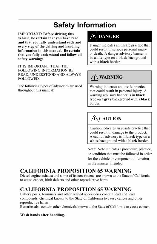
DANGER
Danger indicates an unsafe practice thatcould result in serious personal injuryor death. A danger advisory banner isin white type on a black backgroundwith a black border.
WARNING
Warning indicates an unsafe practicethat could result in personal injury. Awarning advisory banner is in blacktype on a gray background with a blackborder.
CAUTION
Caution indicates an unsafe practice thatcould result in damage to the product.A caution advisory is in black type on awhite background with a black border.
Note: Note indicates a procedure, practice,or condition that must be followed in orderfor the vehicle or component to functionin the manner intended.
CALIFORNIA PROPOSITION 65 WARNINGDiesel engine exhaust and some of its constituents are known to the State of Californiato cause cancer, birth defects and other reproductive harm.
CALIFORNIA PROPOSITION 65 WARNINGBattery posts, terminals and other related accessories contain lead and leadcompounds, chemical known to the State of California to cause cancer and otherreproductive harm.Batteries also contain other chemicals known to the State of California to cause cancer.
Wash hands after handling.

INTRODUCTION 1
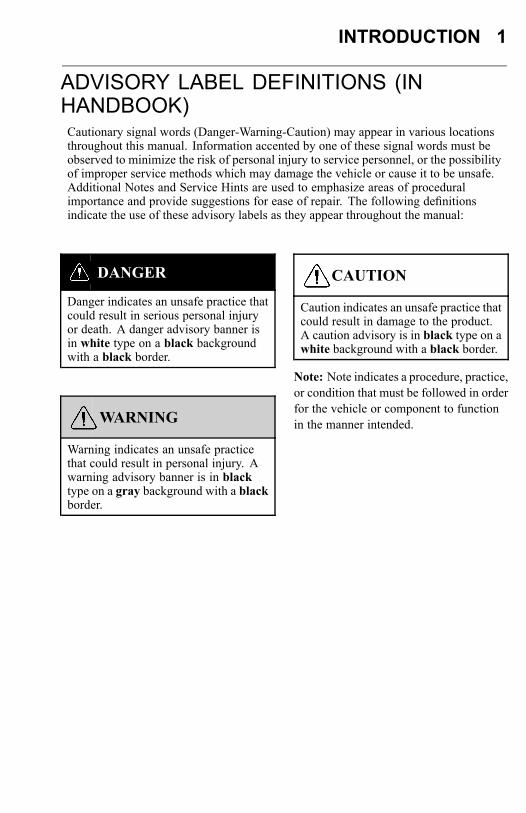
ADVISORY LABEL DEFINITIONS (INHANDBOOK)Cautionary signal words (Danger-Warning-Caution) may appear in various locationsthroughout this manual. Information accented by one of these signal words must beobserved to minimize the risk of personal injury to service personnel, or the possibilityof improper service methods which may damage the vehicle or cause it to be unsafe.Additional Notes and Service Hints are used to emphasize areas of proceduralimportance and provide suggestions for ease of repair. The following definitionsindicate the use of these advisory labels as they appear throughout the manual:
DANGER
Danger indicates an unsafe practice thatcould result in serious personal injuryor death. A danger advisory banner isin white type on a black backgroundwith a black border.
WARNING
Warning indicates an unsafe practicethat could result in personal injury. Awarning advisory banner is in blacktype on a gray background with a blackborder.
CAUTION
Caution indicates an unsafe practice thatcould result in damage to the product.A caution advisory is in black type on awhite background with a black border.
Note: Note indicates a procedure, practice,or condition that must be followed in orderfor the vehicle or component to functionin the manner intended.
2 INTRODUCTION
INFORMATION FOR THE OWNERIf there are questions on the maintenance and performance of your vehicle, pleasediscuss them with your Volvo Truck dealer. Your authorized dealer is required tohave trained mechanics, special tools and spare parts to fully service your vehicle. Ifnecessary, your dealer will contact the manufacturer for any assistance.In addition to this operators manual, there may be additional instruction/operatorsmanuals supplied by component manufacturers. These manuals are placed in theOwner’s Package and placed in the cab. Be sure to read all the manuals thoroughlybefore operating the vehicle.Various safety labels may be placed about the components by the componentmanufacturer. Be sure to read and follow these labels to prevent damage to thevehicle, personal injury or death.Information in this manual refers to Volvo components and Volvo drivetrain. There isalso certain information regarding the Cummins engine. For detailed information onthe Cummins engine or non-Volvo engines and/or drivetrains, contact the respectivemanufacturer.Establish a Preventive Maintenance Program with the help of your local Volvo Truckdealer. A Preventive Maintenance Program makes it possible to maximize the amountof time your vehicle is up and running, resulting in longer component life. This makesfor a safer vehicle by reducing any mechanical failures due to poor maintenancepractices.Various truck warranty coverage plans, contingent on application and weight class,are available. Please contact an authorized Volvo Truck dealer for complete details.Replacement warranty certificates for Volvo Trucks are available from authorizedVolvo dealers.For trucks placed in service after October, 2002 and operating in the USA, Mexico andCanada, Volvo dealers can order copies of the Standard Truck Warranty Certificateand the Premium (Purchased) Truck Coverage Certificate. Warranty Certificate copiesand Operator Manuals are available in either English, Spanish or French. Contact yourauthorized Volvo Truck dealer for more information.
Note: Federal law requires manufacturers to notify owners of its products in the eventof a non-compliance to a Federal Motor Vehicle Safety Standard or if a safety-relateddefect is discovered. If you are not the original owner of this vehicle, please notify usabout the change in ownership at the address below or through an authorized VolvoTruck dealer. This is the only way we will be able to contact you if necessary.Volvo Trucks North AmericaAttn: Vehicle Registration Dept.P.O. Box 26115Greensboro, NC 27402-6115United States of America
INTRODUCTION 3
DO NOT Remove this operators manual from the vehicle. It contains importantoperational and safety information that is needed by all drivers and owners of thisvehicle.
Note: Illustrations in this manual are used for reference only and may differ slightlyfrom the actual vehicle; however, key components addressed in the manual arerepresented as accurately as possible.
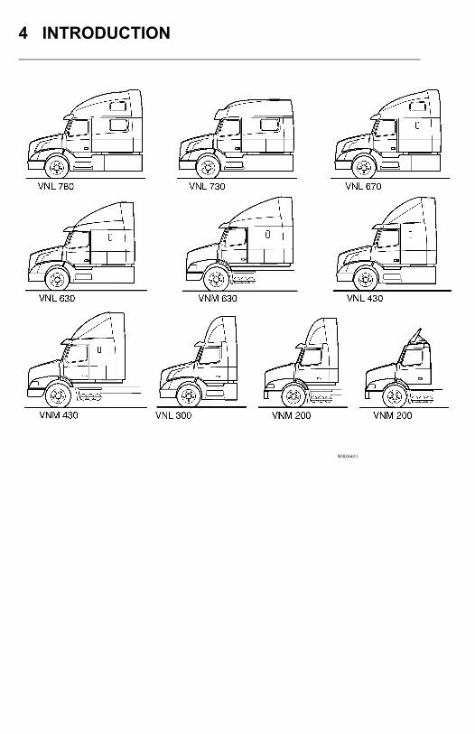
This manual covers Volvo VN series vehicles manufactured by Volvo Trucks NorthAmerica with any of the following designations:
• VNL 780• VNL 730• VNL 670• VNL 630• VNL 430• VNL 300 (Daycab)• VNM 630• VNM 430• VNM 200 (Daycab) Roof fairing choice is optional.
4 INTRODUCTION
W0036011
INTRODUCTION 5
EMISSIONS CONTROL COMPLIANCE
Exhaust and Noise Emissions
GeneralUSA
The Federal Clean Air Act, Section 203 (a) (3), states the following concerning theremoval of air pollution control devices or modification of a certified engine to anon-certified configuration:CAA, Section (a) (3) (A) prohibits any person to remove or render inoperative any(emission control) device or element of design installed on or in a motor vehicle ormotor vehicle engine in compliance with regulations under this part prior to its saleand delivery to the ultimate purchaser, and prohibits any person from knowinglyremoving or rendering inoperative any such device or element of design aftersuch sale and delivery to the ultimate purchaser.” Specifically, please note that noperson may make such changes prior to the sale and delivery of the vehicle to theultimate purchaser, and, in addition, no manufacturer, dealer, or individual may takesuch action after sale and delivery of the vehicle to the ultimate purchaser. For amanufacturer or dealer, the law provides a penalty of up to $37,500 for each engine orpiece of equipment in violation. For anyone else, the civil penalty is assessed up to$3,750 for each day an engine or piece of equipment is operated in violation.
Canada
The same conditions that apply in the USA apply to Canada, with one exception.After the vehicle is sold to a retail customer, that is, the end user, the jurisdictioncontrolling the emission control devices becomes the province in which the vehicle islicensed. No changes should be made that render any or all of the devices inoperative.If the owner/operator wishes to make changes to the emission control devices, checkwith the provincial authority before changes are made.
Mexico
The same conditions that apply in the USA apply to Mexico. Refer to the MexicanFederal Law for Emission Control which adheres to EPA regulations. No changesshould be made that render any or all of the emissions control devices inoperative.If the owner/operator wishes to make changes to the emission control devices, checkwith the state authority before changes are made.
6 INTRODUCTION
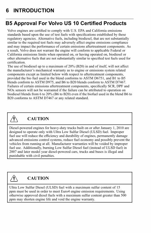
B5 Approval For Volvo US 10 Certified ProductsVolvo engines are certified to comply with U.S. EPA and California emissionsstandards based upon the use of test fuels with specifications established by theseregulatory agencies. Alternative fuels, including biodiesel, that are not substantiallysimilar to the required test fuels may adversely affect engine emissions complianceand may impact the performance of certain emissions aftertreatment components. Asa result, Volvo does not warrant the engine will conform to applicable Federal orCalifornia emissions limits when operated on, or having operated on, biodiesel orother alternative fuels that are not substantially similar to specified test fuels used forcertification.The use of biodiesel up to a maximum of 20% (B20) in and of itself, will not affectthe manufacturer’s mechanical warranty as to engine or emissions system relatedcomponents except as limited below with respect to aftertreatment components,provided the bio fuel used in the blend conforms to ASTM D6751, and B1 to B5blends conform to ASTM D975, and B6 to B20 blends conform to ASTM D7467.Failures of certain emissions aftertreatment components, specifically SCR, DPF andNOx sensors will not be warranted if the failure can be attributed to operation onbiodiesel blends from 6 to 20% (B6 to B20) even if the biofuel used in the blend B6 toB20 conforms to ASTM D7467 or any related standard.
CAUTION
Diesel-powered engines for heavy-duty trucks built on or after January 1, 2010 aredesigned to operate only with Ultra Low Sulfur Diesel (ULSD) fuel. Improperfuel use will reduce the efficiency and durability of engines, permanently damageadvanced emissions control systems, reduce fuel economy and possibly prevent thevehicles from running at all. Manufacturer warranties will be voided by improperfuel use. Additionally, burning Low Sulfur Diesel fuel (instead of ULSD fuel) in2007 and later model year diesel-powered cars, trucks and buses is illegal andpunishable with civil penalties.
CAUTION
Ultra Low Sulfur Diesel (ULSD) fuel with a maximum sulfur content of 15ppm must be used in order to meet Euro4 engine emission requirements. Usingotherwise approved diesel fuels with a maximum sulfur content greater than 500ppm may shorten engine life and void the engine warranty.
INTRODUCTION 7
Air is always present inside the fuel tanks, entering mainly through the tankventilation. With the air being heated and cooled, condensation is formed and wateris mixed in the fuel. To avoid condensation when the vehicle is parked for longerperiods, fill the tanks up to 95% of capacity. Do not fill more than that, as the fuelneeds to have room for expansion during the heat of the day.For additional information about fuel, refer to the Operator’s Manual VehicleMaintenance.
VN: An indicator will appear in the DID screen when there is approximately 3.875liters (0.9 gallons) remaining in the reservoir.
Note: This indicator is optional. It can be deleted.
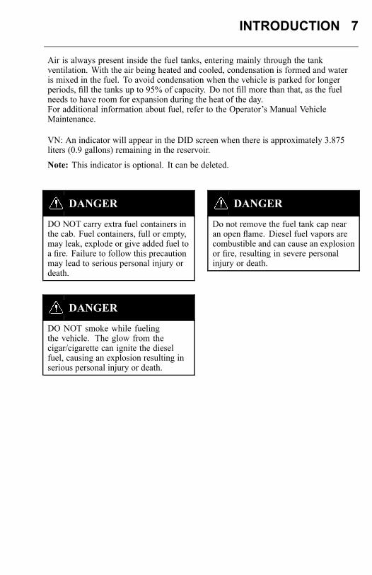
DANGER
DO NOT carry extra fuel containers inthe cab. Fuel containers, full or empty,may leak, explode or give added fuel toa fire. Failure to follow this precautionmay lead to serious personal injury ordeath.
DANGER
DO NOT smoke while fuelingthe vehicle. The glow from thecigar/cigarette can ignite the dieselfuel, causing an explosion resulting inserious personal injury or death.
DANGER
Do not remove the fuel tank cap nearan open flame. Diesel fuel vapors arecombustible and can cause an explosionor fire, resulting in severe personalinjury or death.
8 INTRODUCTION
ENGINES OTHER THAN VOLVO:For specific information on engines other than VOLVO, refer to the enginevendor’s publications.
Noise Emissions
Volvo Trucks North America warrants to the first person who purchases this vehiclefor purposes other than resale and to each subsequent purchaser, that this vehicle asmanufactured by Volvo Trucks North America was designed, built and equippedto conform, at the time it left the control of Volvo Trucks North America, with allapplicable U.S. EPA Noise Control Regulations.
This warranty covers this vehicle as designed, built and equipped by Volvo TrucksNorth America, and is not limited to any particular part, component or system of thevehicle manufactured by Volvo Trucks North America Defects in design, assembly orin any part, component or system of the vehicle as manufactured by Volvo TrucksNorth America, which, at the time it left the control of Volvo Trucks North Americacaused noise emissions to exceed Federal standards, are covered by this warranty forthe life of the vehicle.
Noise Control System, Operator Inspection and MaintenanceRequirements
A Noise Control System Maintenance Log is located in “Noise Control Log”, page 12. This log should be used to document all Noise Control System related maintenance,whether the maintenance results from a specific noise control system inspection, or adeficiency identified during another general maintenance event.
If additional log space is needed, further entries may be added on a separate sheet ofpaper. Store these additions with the main log to preserve a comprehensive record. Itis recommended that copies of all noise emissions related maintenance invoices beretained.
The following Noise Control System inspection and maintenance instructions containsuggested maintenance intervals. These intervals may need adjustment in order tobest accommodate the specific vehicle usage. The following instructions only concernNoise Emissions related items and do not address or modify any general vehiclemaintenance requirements.
The following elements make up the Noise Control System:• Noise Shielding and Insulation Devices• Cooling System• Exhaust System /Aftertreatment DPF System• Intake/Air System• Engine Control, EGR and Fuel Systems
INTRODUCTION 9
Tampering with Noise Control System
Federal law prohibits the following acts or the causing thereof:
(1) The removal or rendering inoperative by any person, other than for purposes ofmaintenance, repair, or replacement, of any device or element of design incorporatedinto any new vehicle for the purpose of noise control prior to its sale or delivery to theultimate purchaser or while it is in use;
or
(2) the use of the vehicle after such device or element of design has been removedor rendered inoperative by any person.
Among the acts that constitute tampering are the acts listed below:• Removal, or rendering inoperative, of any exhaust components, including mufflers,
heavy or double-wall exhaust tubing, flexible tubing or exhaust pipe clamping.• Removal, or rendering inoperative, of the temperature-modulated cooling fan
system.• Removal of the cooling fan shroud.• Removal, or rendering inoperative, of the air cleaner or air intake in-line silencer.• Removal of the sound deadening material from the hood or cab tunnel.• Removal, or rendering inoperative, of the engine speed governor so as to allow
engine speed to exceed the manufacturer’s specifications.• Removal of splash shields located inside the wheel housings.• Removal of engine block shields.• Removal of engine crankcase shields or insulation.• Removal of insulated rocker arm covers.
10 INTRODUCTION
• Removal of transmission noise shields.
Noise Shielding and Insulation DevicesMaintenance
Ensure sound shielding and insulating devices are intact. Inspect components fordamage. Primary system components requiring noise related inspection include thehood, engine compartment insulating materials (including hood insulation, bulkheadinsulation, doghouse insulation, etc.) splash shields, cab skirts, fender shields, andbody panels. Inspect all related fasteners, brackets, and clamps for damage andtightness.
Regulatory Compliance
Acts that constitute tampering with the Noise Shielding and Insulation Devices:
Removing or rendering inoperative the engine and/or transmission noise deadeningpanels, shields or insulating materials.
Removing or rendering inoperative any vehicle body mounted sound insulationcomponents and/or shields (cab or fender shields, skirts, wheel housing splash shields,etc.).
Cooling System
WARNING
DO NOT work near the fan with theengine running or the ignition in the ONposition. The engine fan can engageat any time without warning. Anyonenear the fan when it turns on could beseriously injured.
MaintenanceVisually inspect cooling system components for damage, and/or misalignment.Primary system components requiring noise related inspection include fan blades, fanclutch, fan shroud, fan ring, and recirculation shields. Check fan blades, fan ring, fanshroud, belt tensioner and recirculation shields for any damage. Verify that fan bladesclear the fan ring. Inspect all related fasteners, brackets, and clamps for damage andtightness. Confirm operation of temperature modulated fan clutch.Regulatory ComplianceActs that constitute tampering with the Cooling System:Removing or rendering inoperative cooling system components (such as thetemperature modulated fan clutch, fan shroud, fan ring, recirculation shields, etc.).
Exhaust System
INTRODUCTION 11
WARNING
Hot engine! Avoid all movable parts orhot engine parts, exhaust gases, and/orfluids. A hot engine, exhaust, and/orfluids can cause burns.
MaintenanceMake sure the exhaust system is intact. Inspect for damage, misalignment and/orleakage. Primary system components requiring noise related inspection includeexhaust manifold, turbocharger, and all exhaust system (rigid and flexible) piping.Closely check the system for exhaust leaks. Special attention should be given to allwelds, seams, gaskets, support points, clamps, couplings and connections.Inspect all exhaust system fasteners, brackets, and clamps for damage and tightness.
Regulatory ComplianceActs that constitute tampering with the Exhaust System:Removing or rendering inoperative exhaust system components (such as the pipes,clamps, etc.).
Air Intake/Air Induction System
MaintenanceMake sure the air intake system is intact. Inspect components for damage,misalignment and/or leakage. Primary system components requiring noise relatedinspection include the air cleaner housing, air cleaner element, turbocharger, chargeair cooler and intake manifold.
Also inspect all ducts, pipes, hoses, tubing and elbows used to interconnect thesystem. Special attention should be given to all welds, seams, gaskets, support points,clamps, couplings and connections.Inspect all intake system fasteners, brackets, and clamps for damage and tightness.
Regulatory ComplianceActs that constitute tampering with the Air Intake/Air Induction System:Removing or rendering inoperative air intake/induction system components (filter,filter housings, ducts, etc.).
12 INTRODUCTION
Engine Control, EGR and Fuel SystemsActs that constitute tampering with Engine Control, EGR and Fuel Systems:Removing rendering inoperative, or modifying the engine control system such as theECU, EGR system components, or fuel system components, in order to allow theengine to operate outside of the manufacturer’s specifications is not allowed andviolates both warranty and legislation.
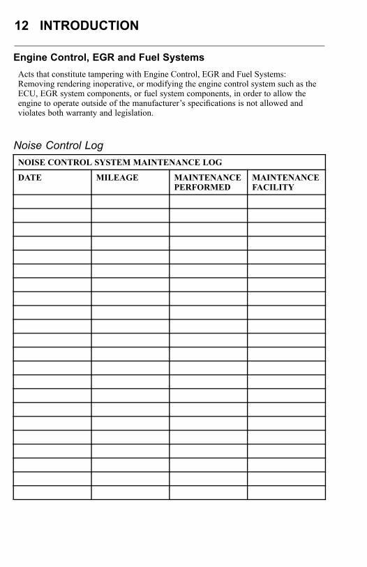
Noise Control LogNOISE CONTROL SYSTEM MAINTENANCE LOG
DATE MILEAGE MAINTENANCEPERFORMED
MAINTENANCEFACILITY

INTRODUCTION 13
VEHICLE DATA
Identification and LabelsIt is extremely important that the correct vehicle model and serial number are givenwhenever replacement parts or service literature are ordered. Using these numbers, aswell as giving the major component model and serial numbers, will prevent delay anderrors in obtaining the correct material. Space is given on the rear inside cover of thismanual for noting the main component model and serial numbers.The full 17-digit Vehicle Identification Number (VIN) is shown on the VehicleIdentification label located in the door opening on the driver’s side. Vehicles forexport, excluding Canadian vehicles, have the full 17-digit VIN on the frame.The 8-digit chassis number is embossed into the bottom flange right hand side of theframe rail and the top flange left hand side of the frame rail, 42 inches (1065 mm)back from the front edge of the frame rail. The use of this number is very helpfulwhen ordering parts for your vehicle.
W0001995

14 INTRODUCTION
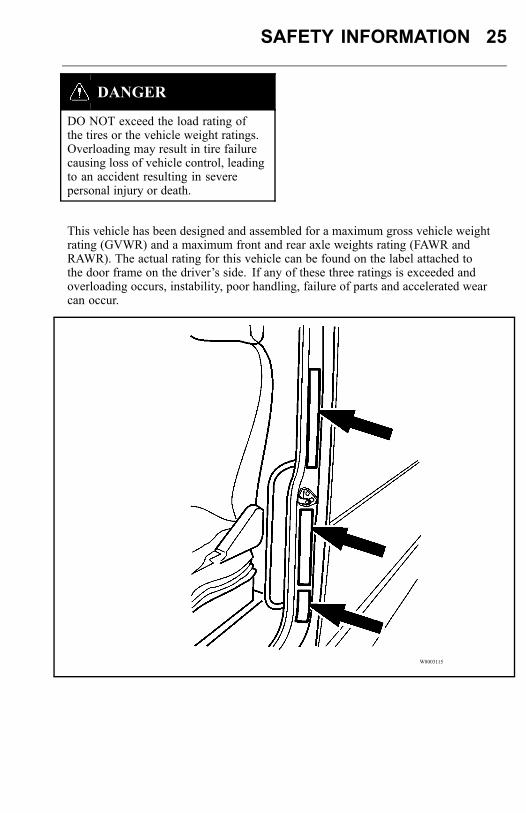
Three labels are located in the rear inside frame of the driver side door frame. Theselabels should not be removed.
W8003115
Note: To deter tampering with the original build information, the information on thelabel will be destroyed if the label is removed. If for any reason a label is damaged,contact your authorized Volvo Truck dealer for a replacement.
Vehicle OrderThe Vehicle Order is a complete and detailed record of all data pertaining to theassembly of the vehicle. It should be filed in the Owner’s office where it will bereadily available for reference. Any changes made to the vehicle must become a partof the Vehicle Order and must comply with all applicable Federal Motor VehicleSafety Standards.
Certification LabelOn the top part of the door frame is the Certification label showing the axle and loadratings for the vehicle as it is built. DO NOT exceed these ratings by overloading.
INTRODUCTION 15
Vehicle Identification LabelThe VIN is shown on the Vehicle Identification label. The VIN includes the vehiclemake, model series, weight class, engine model, where the vehicle was built and thevehicle serial number. This label also shows the truck model designation, majorcomponent model and serial number, cab model and serial number, cab and chassispaint colors, and color numbers.
Noise Emission Control LabelThe Noise Emission Control label is located at the bottom of the three labels on therear inside frame of the driver side door. It is the owner’s responsibility to maintainthe vehicle so that it conforms to EPA regulations.Refer to “Tampering with Noise Control System”, page 9 for a listing of whatconstitutes tampering with the Noise Emissions Control.
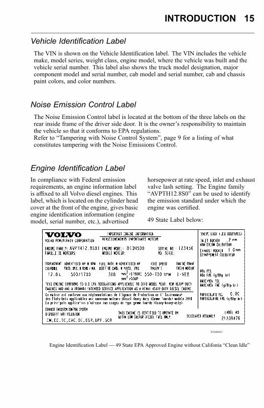
Engine Identification LabelIn compliance with Federal emissionrequirements, an engine information labelis affixed to all Volvo diesel engines. Thislabel, which is located on the cylinder headcover at the front of the engine, gives basicengine identification information (enginemodel, serial number, etc.), advertised
horsepower at rate speed, inlet and exhaustvalve lash setting. The Engine family“AVPTH12.8S0” can be used to identifythe emission standard under which theengine was certified.
49 State Label below:
W2040453
Engine Identification Label — 49 State EPA Approved Engine without Califonia “Clean Idle”
16 INTRODUCTION
CAUTION
To maintain compliance with emissionregulations, engine settings should notbe changed from those specified on theengine information label.
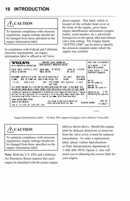
In compliance with Federal and Californiaemission requirements, an engineinformation label is affixed to all Volvo
diesel engines. This label, which islocated on the cylinder head cover atthe front of the engine, gives basicengine identification information (enginemodel, serial number, etc.), advertisedhorsepower at rate speed, inlet and exhaustvalve lash setting. The Engine family“AVPTH12.8S0” can be used to identifythe emission standard under which theengine was certified.
W2040454
Engine Identification Label — 50 State EPA Approved Engine with Califonia “Clean Idle”
CAUTION
To maintain compliance with emissionregulations, engine settings should notbe changed from those specified on theengine information label.
Note: Both the U.S. EPA and CaliforniaAir Resources Board requires that eachengine be identified with the proper engine
label as shown above. Should this enginelabel be defaced, destroyed, or removedfrom the valve cover, it must be replacedimmediately. To order a replacementlabel, please contact Specificationsor Parts Interpretations department at1–800–888–9878, Option 2, who willassist you in obtaining the correct label foryour engine.
INTRODUCTION 17
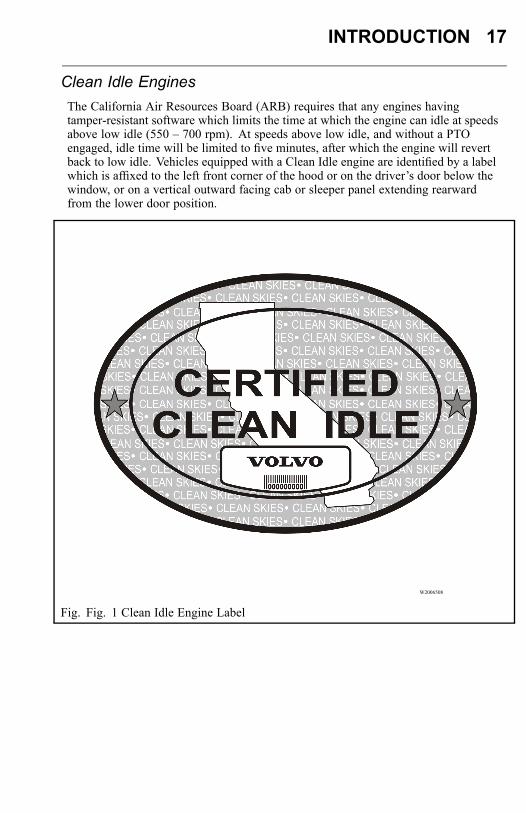
Clean Idle EnginesThe California Air Resources Board (ARB) requires that any engines havingtamper-resistant software which limits the time at which the engine can idle at speedsabove low idle (550 – 700 rpm). At speeds above low idle, and without a PTOengaged, idle time will be limited to five minutes, after which the engine will revertback to low idle. Vehicles equipped with a Clean Idle engine are identified by a labelwhich is affixed to the left front corner of the hood or on the driver’s door below thewindow, or on a vertical outward facing cab or sleeper panel extending rearwardfrom the lower door position.
W2006508
Fig. Fig. 1 Clean Idle Engine Label
18 INTRODUCTION
Component Labels
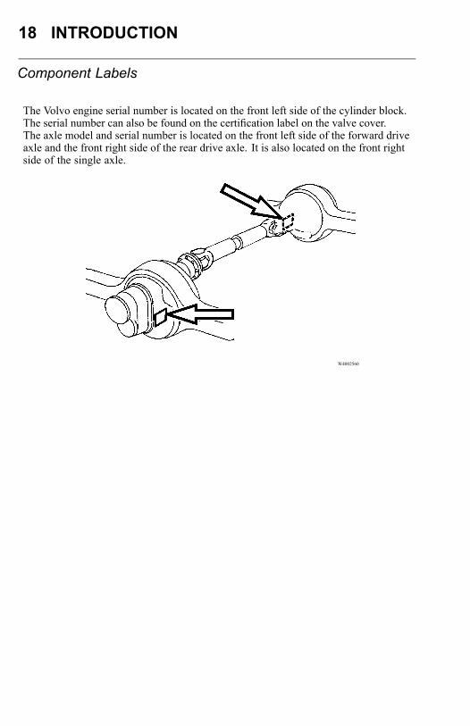
The Volvo engine serial number is located on the front left side of the cylinder block.The serial number can also be found on the certification label on the valve cover.The axle model and serial number is located on the front left side of the forward driveaxle and the front right side of the rear drive axle. It is also located on the front rightside of the single axle.
W4002560
INTRODUCTION 19
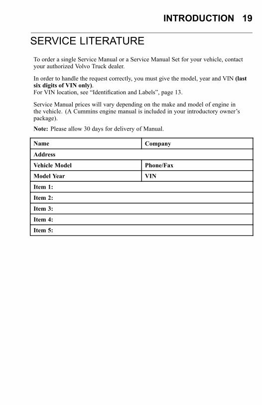
SERVICE LITERATURETo order a single Service Manual or a Service Manual Set for your vehicle, contactyour authorized Volvo Truck dealer.
In order to handle the request correctly, you must give the model, year and VIN (lastsix digits of VIN only).For VIN location, see “Identification and Labels”, page 13.
Service Manual prices will vary depending on the make and model of engine inthe vehicle. (A Cummins engine manual is included in your introductory owner’spackage).
Note: Please allow 30 days for delivery of Manual.
Name Company
Address
Vehicle Model Phone/Fax
Model Year VIN
Item 1:
Item 2:
Item 3:
Item 4:
Item 5:
20 INTRODUCTION
SERVICE ASSISTANCE
Your authorized Volvo Truck dealer is trained and equipped to perform expert serviceon your Volvo vehicle. Your dealer has direct access to Volvo Trucks North Americafor technical help, parts or service information.There is also a direct number to Volvo Action Service (VAS), staffed 24 hours a day, ifyou are in need of assistance. The number to the Customer Support Center is: 1 (800)528–6586 [or (800) 52–VOLVO]. Also on the internet: www.vas.volvo.comVAS offers:
Delivery Assurance— If you need roadside assistance, VAS can arrange for loadforwarding or equipment rental.Personal Assurance— Trained staff for handling any vehicle problems.Uptime Assurance— VAS will locate the nearest service provider and guaranteepayment so you can get on the road as soon as possible.Price Assurance— VAS audits service and parts billing to ensure guaranteed laborrates and preferred parts pricing for Volvo components.
INTRODUCTION 21
REPORTING SAFETY DEFECTS
United StatesIf you believe that your vehicle has a defect which could cause a crash, injury or death,you should immediately inform the National Highway Traffic Safety Administration(NHTSA), in addition to notifying Volvo Trucks North America.If NHTSA receives similar complaints, it may open an investigation and if it findsthat a safety defect exists in a group of vehicles, it may order a recall and remedycampaign. However, NHTSA cannot become involved in individual problemsbetween you, your distributor, or Volvo Trucks North America.To contact NHTSA, either call the U.S. Government’s Vehicle Safety Hotline toll-freeat 1-888-327-4236 (TTY: 1-800-424-9153); go to http://www.NHTSA.gov; or writeto: Administrator, National Highway Traffic Safety Administration, 400 SeventhStreet, S.W., Washington, DC 20590. You can also obtain other information aboutmotor vehicle safety from the Vehicle Safety Hotline.
CanadaCanadian customers who wish to report a safety-related defect to: TransportCanada Defect Investigations and Recalls, may telephone the toll free hotlineat 1-800-333-0510, or contact Transport Canada by mail at Transport Canada,ASFAD, Place de Ville Tower C, 330 Sparks Street, Ottawa ON K1A 0N5.For additional road safety information, please visit the Road Safety website athttp://www.tc.gc.ca/roadsafety/menu.htm.
MexicoVolvo Trucks de Mexico, S.A. de C.V. should be informed immediately if you believethe vehicle has a defect that could cause a vehicle accident, injury or death. ContactVolvo Trucks de Mexico by calling 011-52-55-50-81-68-50 or by writing to: VolvoTrucks de Mexico, S.A. de C.V., Prol. Paseo de la Reforma 600, 1er. Piso 121, Col.Santa Fe Pena Blanca, C.P. 01210, Mexico, D.F. Within Mexico, call 01 (800) 90 94900.

22 INTRODUCTION
EVENT DATA RECORDING DEVICESYour Volvo vehicle is equipped with a device generally referred to as an "event datarecorder" or "EDR." Please note that while the term "event data recorder" is typicallyused throughout the motor vehicle industry, not every EDR is the same; i.e., they donot all record the same data elements. The EDR on your Volvo vehicle records vehiclespeed, engine rpm, time and date, plus a variety of pedal and switch positions, bothbefore and after an "event." Sudden vehicle deceleration or the occurrence of certainother vehicle operational characteristics will define (trigger) an "event.”If you have a question about your EDR, please contact your Volvo dealer or regionalservice office.
SAFETY INFORMATION 23
GENERAL SAFETY INFORMATION
Operating the Vehicle
DANGER
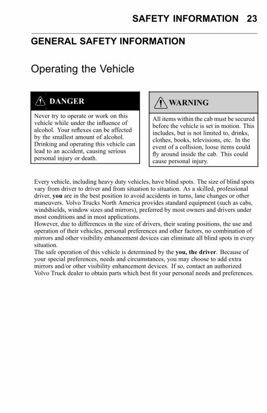
Never try to operate or work on thisvehicle while under the influence ofalcohol. Your reflexes can be affectedby the smallest amount of alcohol.Drinking and operating this vehicle canlead to an accident, causing seriouspersonal injury or death.
WARNING
All items within the cab must be securedbefore the vehicle is set in motion. Thisincludes, but is not limited to, drinks,clothes, books, televisions, etc. In theevent of a collision, loose items couldfly around inside the cab. This couldcause personal injury.
Every vehicle, including heavy duty vehicles, have blind spots. The size of blind spotsvary from driver to driver and from situation to situation. As a skilled, professionaldriver, you are in the best position to avoid accidents in turns, lane changes or othermaneuvers. Volvo Trucks North America provides standard equipment (such as cabs,windshields, window sizes and mirrors), preferred by most owners and drivers undermost conditions and in most applications.However, due to differences in the size of drivers, their seating positions, the use andoperation of their vehicles, personal preferences and other factors, no combination ofmirrors and other visibility enhancement devices can eliminate all blind spots in everysituation.The safe operation of this vehicle is determined by the you, the driver. Because ofyour special preferences, needs and circumstances, you may choose to add extramirrors and/or other visibility enhancement devices. If so, contact an authorizedVolvo Truck dealer to obtain parts which best fit your personal needs and preferences.

24 SAFETY INFORMATION
Operating in Bobtail Mode
CAUTION
When operating bobtail, be certain thatglad hands, trailer air hoses, electricalcable and connectors are properlystowed and secure. Do not allow themto rub or chafe on other components.
Depending on customer specification, some tractors may be equipped with a bobtailair brake proportioning valve which automatically redistributes the braking forcebetween front and rear axles when not hooked up to a semitrailer (bobtail operation).When operating in bobtail mode, the rear brake chambers receive reduced orproportional brake air pressure. When the tractor is towing a trailer, the rear brakechambers will receive full (normal) brake pressure. For tractors with no proportioningvalve, the ABS system automatically controls brake pressure.
DANGER
Under no circumstances should thepublished GVWR, FAWR, and/orRAWR be exceeded. Failure to observethese precautions can lead to the loss ofvehicle control, resulting in a vehicleaccident causing serious personal injuryor death.
SAFETY INFORMATION 25
DANGER
DO NOT exceed the load rating ofthe tires or the vehicle weight ratings.Overloading may result in tire failurecausing loss of vehicle control, leadingto an accident resulting in severepersonal injury or death.
This vehicle has been designed and assembled for a maximum gross vehicle weightrating (GVWR) and a maximum front and rear axle weights rating (FAWR andRAWR). The actual rating for this vehicle can be found on the label attached tothe door frame on the driver’s side. If any of these three ratings is exceeded andoverloading occurs, instability, poor handling, failure of parts and accelerated wearcan occur.
W8003115
26 SAFETY INFORMATION
VORAD® COLLISION WARNING SYSTEMThe Eaton® VORAD® computerized Collision Warning System constantly monitorsvehicles ahead with a front end-mounted radar and in a blind spot area with anoptional side-mounted radar. The Collision Warning System warns the driver ofpotentially dangerous situations by activating visual and audible alerts.
DANGER
The Eaton® VORAD® CollisionWarning System is intended solely asan aid for an alert and conscientiousprofessional driver. It is not to be usedor relied upon to operate the vehicle.Use this system together with rear viewmirrors and other instrumentation tomaintain safe operation of the vehicle.Operate a VORAD® equipped vehiclein the same safe manner as if VORAD®was not installed.The Eaton® VORAD® CollisionWarning System is not a substitutefor safe driving procedures nor will itcompensate for any driver impairment,such as drugs, alcohol or fatigue.The Eaton® VORAD® CollisionWarning System may provide little orno warning for some hazards like: alertsfor pedestrians, animals, oncomingvehicles and cross traffic. SmartCruisewill not react to stationary objects and itdoes not have the capability to stop thevehicle.Failure to follow these instructions maylead to a vehicle accident resulting insevere personal injury or death.
If your vehicle is equipped with the Eaton® VORAD® Collision Warning System,read the manufacturer’s Driver Reference Manual before taking the vehicle on theroad.

SAFETY INFORMATION 27
ADVISORY LABELSThroughout this book you will find paragraphs labeled Danger, Warning, Caution,Note and Service Hint. Danger, Caution and Warning labels are also found invarious locations on the vehicle to alert drivers, operators and service techniciansto situations which can cause personal injury or equipment damage. The labelsshown are applicable to the VN model chassis at the time of publication and arerepresentative of what can be typically found. (Your vehicle may not contain all ofthe labels illustrated in this handbook.) These labels are for your benefit. Please lookthrough this section and note the labels, their locations and what they explain. Besure to replace any label that is damaged.
28 SAFETY INFORMATION
CAB ENTRY AND EXIT
General
DANGER
DO NOT stand on the steps or any otherpart of the vehicle while it is in motion.The steps and the back of cab accessdeck plates are only for entering/exitingthe vehicle and not for riding on.Failure to heed this warning can resultin serious personal injury or death.
DANGER
Steps are designed to be slip resistantand to provide a stable surface forentering or exiting the cab. However,accumulation of ice, dirt, lubricants,etc. on the steps can make enteringor exiting hazardous. Always makesure the steps are free from slipperysubstances. Failure to follow thisguideline may result in a fall that cancause serious personal injury or death.
WARNING
To avoid personal injury due to a slipand/or fall, observe all the guidelinesexplained in this section.
WARNING
Wearing shoes with soles that are dirtyor wet increases the chance of injuryfrom slipping and falling. Be carefulwhen entering the cab with dirty or wetsoles.
WARNING
Both the operator and passenger shouldexercise caution when entering orexiting the cab. Use the steps and grabhandles to safely get in and out of thecab.
WARNING
Always check the security of cab panel,fairing and steps before use. Ensure thatthe cab panels or fairings are completelyclosed and the handles are in the lockedposition.
CAUTION
DO NOT open fairing while cab dooris open, this can result in paint damageon the fairing.
SAFETY INFORMATION 29
W8003120
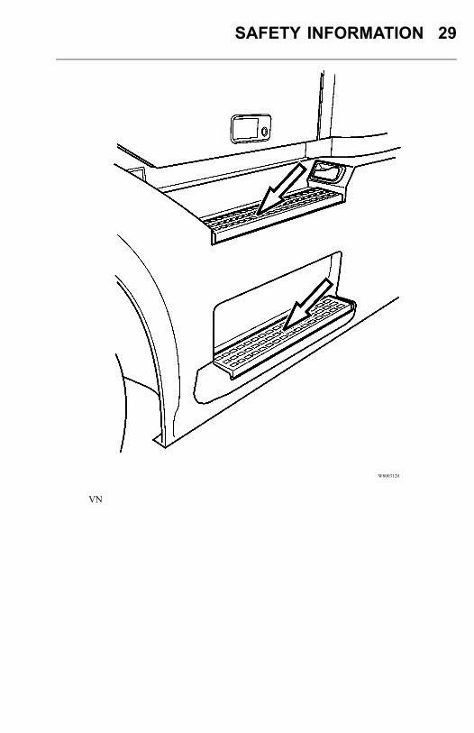
VN
30 SAFETY INFORMATION
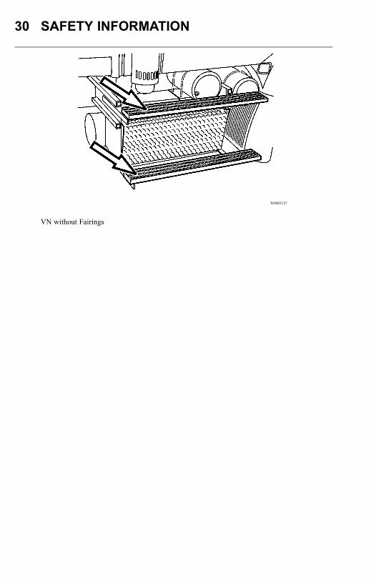
W8003127
VN without Fairings

SAFETY INFORMATION 31
General Entry Guidelines
WARNING
To avoid personal injury due to a slipand/or fall, observe the followingguidelines.
BE SURE TO FOLLOW ALL OF THESE INSTRUCTIONS BEFOREENTERING OR EXITING THE CAB OR THE AREA BEHIND THE CAB.1 Always have three limbs (one foot and two hands or two feet and one hand) in
contact with the vehicle at all times when entering or exiting the cab or the areabehind the cab.
2 Be certain you have a firm handhold and/or stable foot position before transferringweight to that position. For example, do not start to put weight on a foot until youare certain your foot is properly on the step and will not slip when you transferyour weight.
3 DO NOT climb on top of the frame, fuel tanks or storage boxes to make trailerhook-ups.
4 If the vehicle is equipped with air fairings, do not use the side mounted fairing(wind deflector) brackets and braces as steps or grab handles.
5 If the vehicle is equipped with air fairings, do not use the side mounted fairing(wind deflector) brackets and braces as steps or grab handles.
6 Be certain that all grab handles, steps and related parts are in good workingcondition. Any defects should be reported and repaired before using the grabhandles and steps.
7 Be certain that all grab handles, steps and related parts are in good workingcondition. Any defects should be reported and repaired before using the grabhandles and steps.
8 DO NOT step on the curved surface of the fuel tanks. They may be slippery fromsnow, mud, ice, water, spilled fuel or other slippery substances.
9 If a step is mounted to the top of the battery box, be certain that the battery boxcover is properly fastened before stepping.
10 If a vehicle is equipped with removable chassis fairings or cab panels, be certainthe fairing or cab panel is properly fastened before using steps.
11 DO NOT jump from the cab or from the steps to the ground.12 Always face the cab when entering or exiting.13 DO NOT hold anything in your hands when entering or exiting the cab or the area
behind the cab. Log books, cups, clipboards, jackets, luggage and the like can beplaced on the cab floor or rear deck plate before entering or exiting.

32 SAFETY INFORMATION
14. Make sure your safety belt is disconnected before exiting the cab.
15. Make sure the safety belt is fully retracted and out of the way prior to entering orexiting the cab.
16. DO NOT put your foot on any surface that does not have slip resistant, self-cleaning material. If there is no step material, the surface may be slippery and youmay fall.
17. Before entering or exiting, be certain that the soles of your shoes/boots are freefrom grease, mud or any other substance which could make them slippery.
18. Always put the foot flat on the top of the step. DO NOT place your foot on theside or edge of the step.
SAFETY INFORMATION 33
Driver Side Entry/Exit
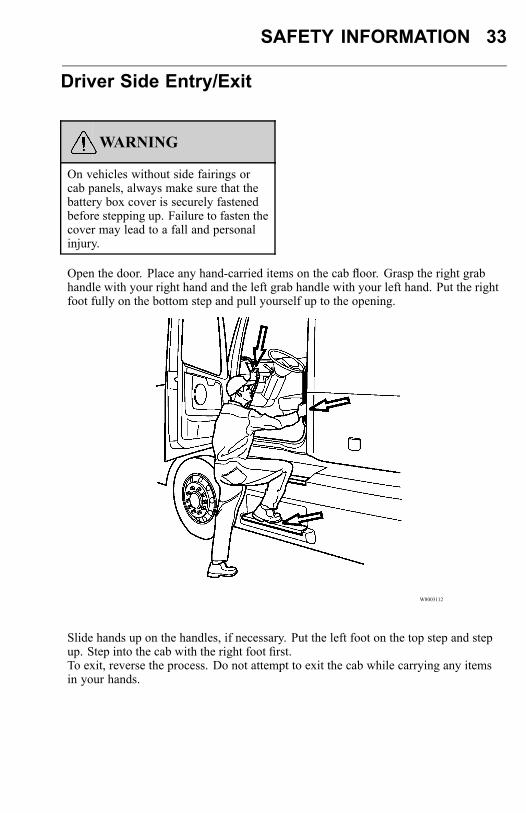
WARNING
On vehicles without side fairings orcab panels, always make sure that thebattery box cover is securely fastenedbefore stepping up. Failure to fasten thecover may lead to a fall and personalinjury.
Open the door. Place any hand-carried items on the cab floor. Grasp the right grabhandle with your right hand and the left grab handle with your left hand. Put the rightfoot fully on the bottom step and pull yourself up to the opening.
W8003112
Slide hands up on the handles, if necessary. Put the left foot on the top step and stepup. Step into the cab with the right foot first.To exit, reverse the process. Do not attempt to exit the cab while carrying any itemsin your hands.
34 SAFETY INFORMATION
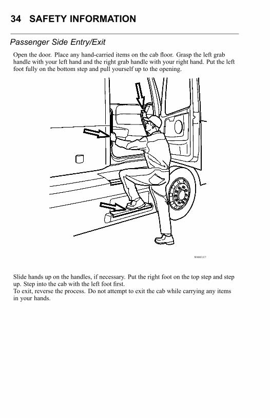
Passenger Side Entry/ExitOpen the door. Place any hand-carried items on the cab floor. Grasp the left grabhandle with your left hand and the right grab handle with your right hand. Put the leftfoot fully on the bottom step and pull yourself up to the opening.
W8003117
Slide hands up on the handles, if necessary. Put the right foot on the top step and stepup. Step into the cab with the left foot first.To exit, reverse the process. Do not attempt to exit the cab while carrying any itemsin your hands.
SAFETY INFORMATION 35
Behind the Cab Access
WARNING
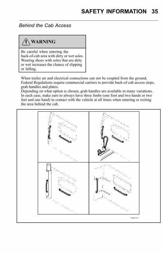
Be careful when entering theback-of-cab area with dirty or wet soles.Wearing shoes with soles that are dirtyor wet increases the chance of slippingor falling.
When trailer air and electrical connections can not be coupled from the ground,Federal Regulations require commercial carriers to provide back-of-cab access steps,grab handles and plates.Depending on what option is chosen, grab handles are available in many variations.In each case, make sure to always have three limbs (one foot and two hands or twofeet and one hand) in contact with the vehicle at all times when entering or exitingthe area behind the cab.
W8001363
36 SAFETY INFORMATION
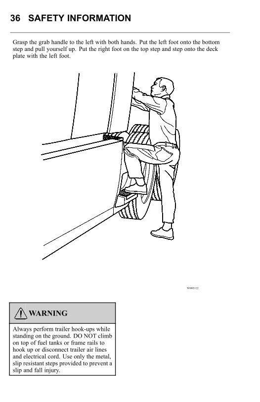
Grasp the grab handle to the left with both hands. Put the left foot onto the bottomstep and pull yourself up. Put the right foot on the top step and step onto the deckplate with the left foot.
W8003122
WARNING
Always perform trailer hook-ups whilestanding on the ground. DO NOT climbon top of fuel tanks or frame rails tohook up or disconnect trailer air linesand electrical cord. Use only the metal,slip resistant steps provided to prevent aslip and fall injury.
SAFETY INFORMATION 37
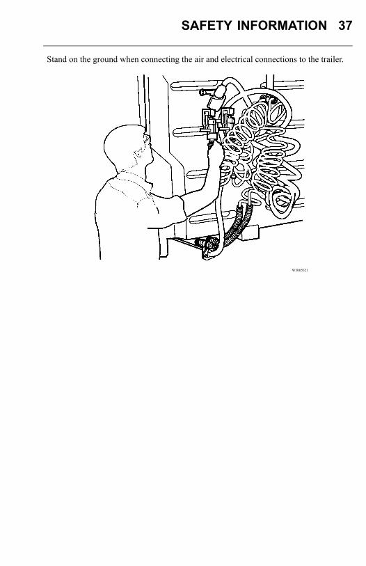
Stand on the ground when connecting the air and electrical connections to the trailer.
W3005321
38 SAFETY INFORMATION
ENTERING SLEEPER FROM SEAT
Standard Gear Lever
CAUTION
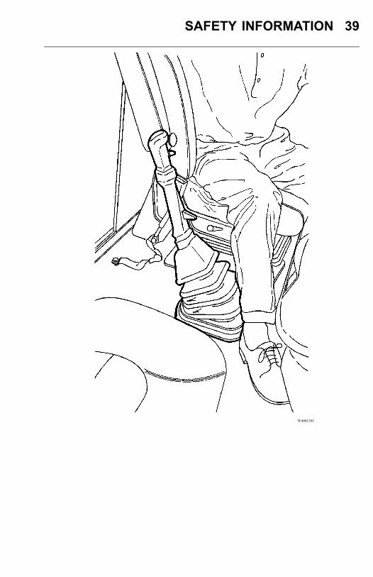
Be careful when standing to your feet inthe seat area, headroom is limiting.
When moving from the driver seat to thesleeper section, follow this procedure:
• Make sure the parking brakes are set.• Place the gear shift lever in a gear position toward the rear of the vehicle.• If equipped with an adjustable steering column, move the steering wheel up and
forward.• Place the left hand on the steering wheel and the right hand on the top of the gear
lever.• Move the right foot out to the middle of the floor.• Lift the upper body, supported by the hands on the steering wheel and the gear
lever and step out from the seat area.
SAFETY INFORMATION 39
W4001391
40 SAFETY INFORMATION
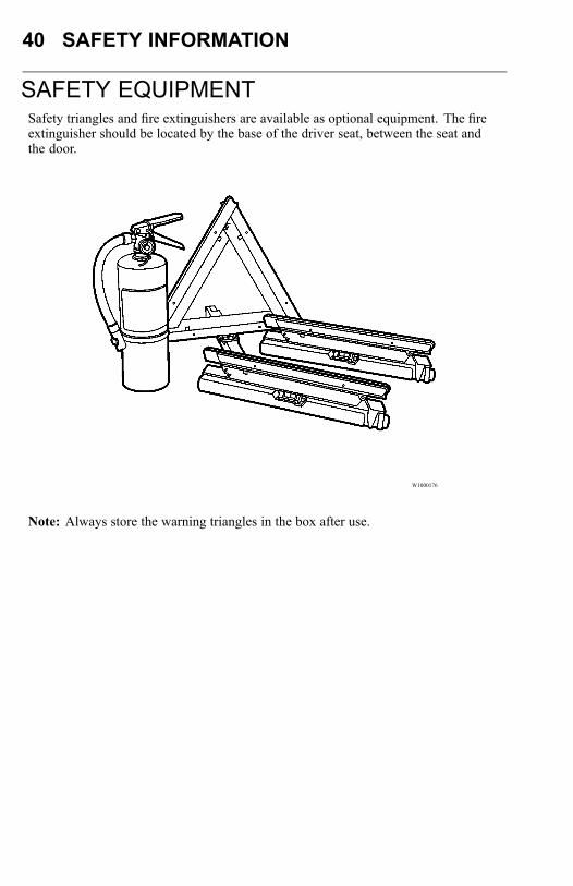
SAFETY EQUIPMENTSafety triangles and fire extinguishers are available as optional equipment. The fireextinguisher should be located by the base of the driver seat, between the seat andthe door.
W1000176
Note: Always store the warning triangles in the box after use.
SAFETY INFORMATION 41
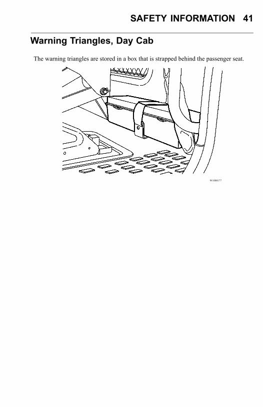
Warning Triangles, Day Cab
The warning triangles are stored in a box that is strapped behind the passenger seat.
W1000177
42 SAFETY INFORMATION
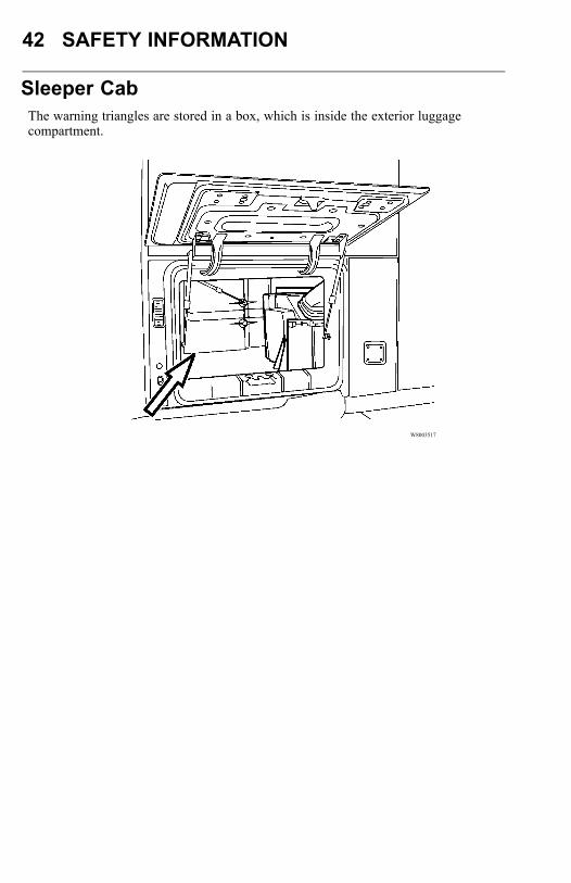
Sleeper CabThe warning triangles are stored in a box, which is inside the exterior luggagecompartment.
W8003517
SAFETY INFORMATION 43
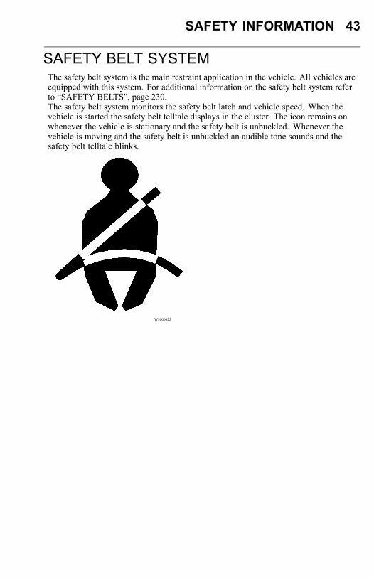
SAFETY BELT SYSTEMThe safety belt system is the main restraint application in the vehicle. All vehicles areequipped with this system. For additional information on the safety belt system referto “SAFETY BELTS”, page 230.The safety belt system monitors the safety belt latch and vehicle speed. When thevehicle is started the safety belt telltale displays in the cluster. The icon remains onwhenever the vehicle is stationary and the safety belt is unbuckled. Whenever thevehicle is moving and the safety belt is unbuckled an audible tone sounds and thesafety belt telltale blinks.
W3000625
44 SAFETY INFORMATION
SRS AIRBAGThe SRS airbag is intended to supplement — not replace — the standard safety belt.The airbag is not deployed when the truck is hit from behind, from the side or if it rollsover. For best protection, sit in a normal, upright position. Always wear the safety belt.For added safety, the vehicle may be equipped with an airbag or SRS (SupplementalRestraint System) as a supplement to the standard three-point anchored safety belt.The SRS is designed to reduce the risk of injury to the driver’s face and upper part ofthe body. Together with the safety belt, the airbag helps prevent the driver from beingthrown against the steering wheel, windshield or other hard surfaces in the cab.The Volvo SRS Airbag provides increased protection in frontal collisions, where thevehicle collides with a fixed or heavy object with enough force to activate the sensorswhich then activate the airbag. Damage to the vehicle is not always proportional towhether the SRS Airbag deploys or not.The SRS Airbag is not designed to be activated with:
• Collision from the sides• Collision from the rear• Rolling over• Head-on collisions at low speed or against soft objects such as bushes, snow
drifts, etc.
SRS System
WARNING
Never attempt to drive with a deployedairbag. With the bag hanging out of thehub of the steering wheel, the truck maybe more difficult to steer. In addition,other safety systems may be damaged.Continuous exposure to the smoke anddust created during the deployment ofthe airbag can cause irritation to theskin and eyes.
SAFETY INFORMATION 45
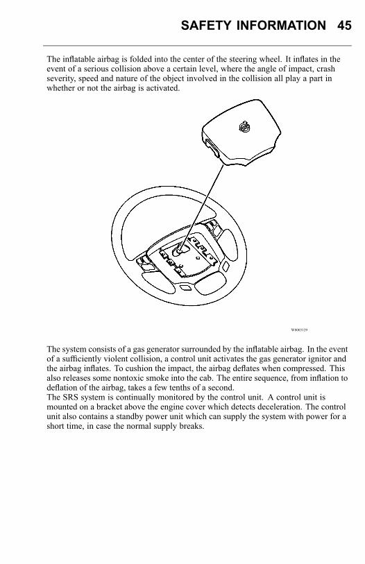
The inflatable airbag is folded into the center of the steering wheel. It inflates in theevent of a serious collision above a certain level, where the angle of impact, crashseverity, speed and nature of the object involved in the collision all play a part inwhether or not the airbag is activated.
W8003129
The system consists of a gas generator surrounded by the inflatable airbag. In the eventof a sufficiently violent collision, a control unit activates the gas generator ignitor andthe airbag inflates. To cushion the impact, the airbag deflates when compressed. Thisalso releases some nontoxic smoke into the cab. The entire sequence, from inflation todeflation of the airbag, takes a few tenths of a second.The SRS system is continually monitored by the control unit. A control unit ismounted on a bracket above the engine cover which detects deceleration. The controlunit also contains a standby power unit which can supply the system with power for ashort time, in case the normal supply breaks.
46 SAFETY INFORMATION
W8003119
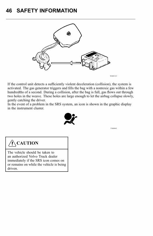
If the control unit detects a sufficiently violent deceleration (collision), the system isactivated. The gas generator triggers and fills the bag with a nontoxic gas within a fewhundredths of a second. During a collision, after the bag is full, gas flows out throughtwo holes in the weave. These holes are large enough to let the airbag collapse slowly,gently catching the driver.In the event of a problem in the SRS system, an icon is shown in the graphic displayin the instrument cluster.
T3008842
CAUTION
The vehicle should be taken toan authorized Volvo Truck dealerimmediately if the SRS icon comes onor remains on while the vehicle is beingdriven.
SAFETY INFORMATION 47
If a problem develops in the system, the CHECK tell-tale will come on togetherwith the SRS tell-tale.
W3005170
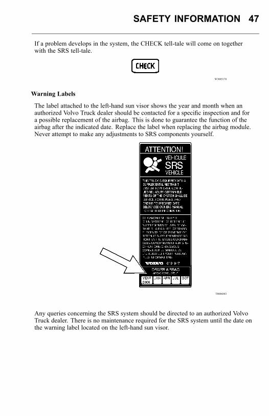
Warning Labels
The label attached to the left-hand sun visor shows the year and month when anauthorized Volvo Truck dealer should be contacted for a specific inspection and fora possible replacement of the airbag. This is done to guarantee the function of theairbag after the indicated date. Replace the label when replacing the airbag module.Never attempt to make any adjustments to SRS components yourself.
T8006843
Any queries concerning the SRS system should be directed to an authorized VolvoTruck dealer. There is no maintenance required for the SRS system until the date onthe warning label located on the left-hand sun visor.
48 SAFETY INFORMATION
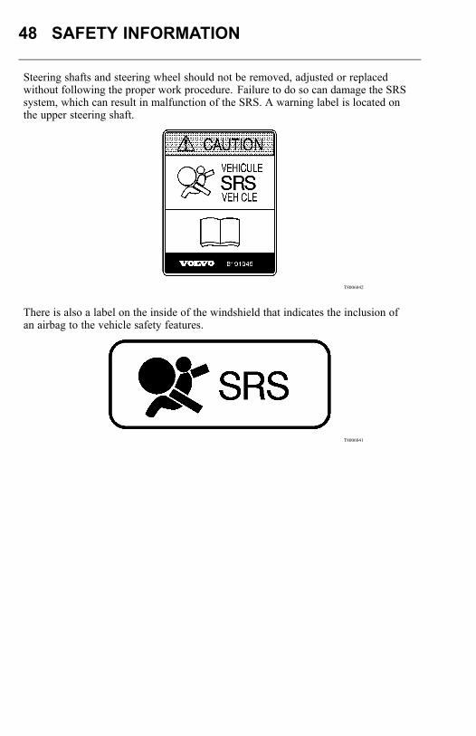
Steering shafts and steering wheel should not be removed, adjusted or replacedwithout following the proper work procedure. Failure to do so can damage the SRSsystem, which can result in malfunction of the SRS. A warning label is located onthe upper steering shaft.
T8006842
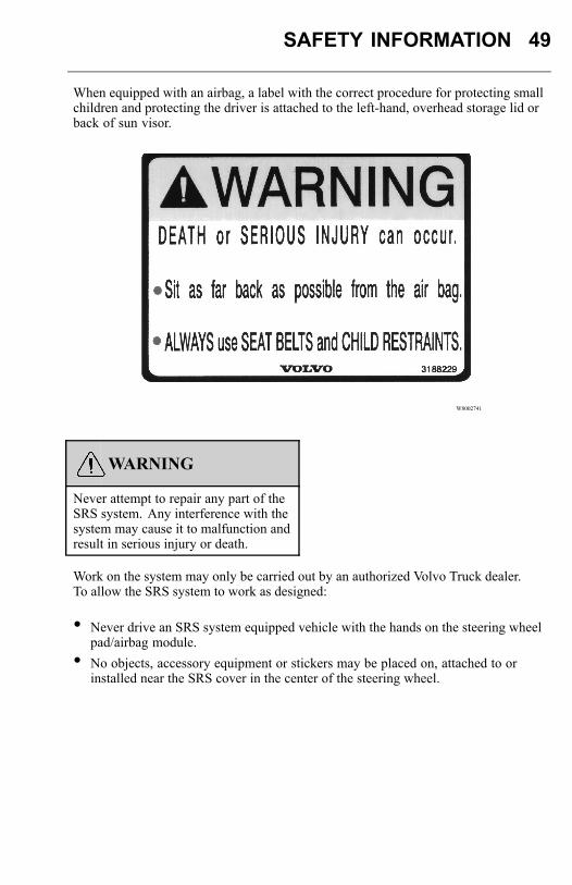
There is also a label on the inside of the windshield that indicates the inclusion ofan airbag to the vehicle safety features.
T8006841
SAFETY INFORMATION 49
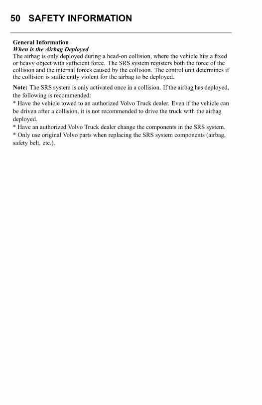
When equipped with an airbag, a label with the correct procedure for protecting smallchildren and protecting the driver is attached to the left-hand, overhead storage lid orback of sun visor.
W8002741
WARNING
Never attempt to repair any part of theSRS system. Any interference with thesystem may cause it to malfunction andresult in serious injury or death.
Work on the system may only be carried out by an authorized Volvo Truck dealer.To allow the SRS system to work as designed:
• Never drive an SRS system equipped vehicle with the hands on the steering wheelpad/airbag module.
• No objects, accessory equipment or stickers may be placed on, attached to orinstalled near the SRS cover in the center of the steering wheel.
50 SAFETY INFORMATION
General InformationWhen is the Airbag DeployedThe airbag is only deployed during a head-on collision, where the vehicle hits a fixedor heavy object with sufficient force. The SRS system registers both the force of thecollision and the internal forces caused by the collision. The control unit determines ifthe collision is sufficiently violent for the airbag to be deployed.
Note: The SRS system is only activated once in a collision. If the airbag has deployed,the following is recommended:* Have the vehicle towed to an authorized Volvo Truck dealer. Even if the vehicle canbe driven after a collision, it is not recommended to drive the truck with the airbagdeployed.* Have an authorized Volvo Truck dealer change the components in the SRS system.* Only use original Volvo parts when replacing the SRS system components (airbag,safety belt, etc.).
SAFETY INFORMATION 51
When is the Airbag not DeployedNot all frontal collisions activate the SRS system. In a collision with a soft object (asnow drift or bush for example, or a hard or fixed object at low speed), there is noneed for the SRS system to be activated. The airbag is usually not inflated in responseto side-on collisions, impacts from the rear or if the vehicle overturns. The extent ofdamage to the vehicle is no measure of how well the SRS system works.
Can the Airbag be Deployed AccidentallyThe complete SRS system is constructed so that the airbag only inflates in particularcollision conditions. The SRS system has its own diagnostic unit which continuouslymonitors the functioning of the system.
Heart of the Volvo Safety SystemThe three-point anchored safety belt is the heart of the Volvo safety system. Thebelt should be worn at all times. The SRS system is intended as a supplement to thethree-point anchored safety belt.
52 INSTRUMENTS AND CONTROLS
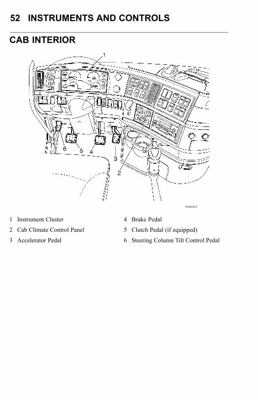
CAB INTERIOR
W8003838
1 Instrument Cluster
2 Cab Climate Control Panel
3 Accelerator Pedal
4 Brake Pedal
5 Clutch Pedal (if equipped)
6 Steering Column Tilt Control Pedal
INSTRUMENTS AND CONTROLS 53
INSTRUMENT PANEL
Tell-TalesA tell-tale is a display that indicates the actuation of a device, a correct or defectivecondition, or a failure to function.The operator should become familiar with these symbols in order to recognize andreact (if necessary) to the indicated condition. Tell-tale symbols are shown in theinstrument panel illustrations on the following pages.
ColorsTo promote visual recognition internationally, specific colors for tell-tales have beenestablished. Unless governmental regulations (in the area where the vehicle is to beused) or engineering directives specify otherwise, the standard colors are:• Blue— high-beam headlights/engine maintenance• Flashing Green — turn signals• Flashing Red— hazard condition involving the safety of personnel• Steady Green— system in operation• Steady Red— warning, immediate action required• Amber— early warning, such as low fuel or Anti-Lock Brake System (ABS)
malfunction
54 INSTRUMENTS AND CONTROLS
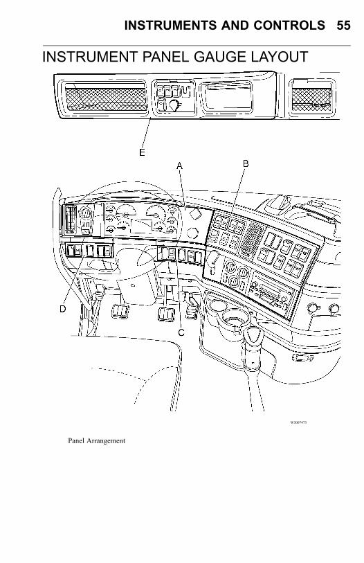
Panel ArrangementYour view from the driver seat should look something like the illustrations shown.The layout is designed to provide the operator with a good view of the gauges andcontrols (which are placed so they are within easy reach). The instrument panel, asshown in the following drawing, is broken down into several main sections. Foreasy identification we refer to them, from left to right, as Panels A, B, C, D, E and F(where necessary).
Note: This section shows the instruments and controls available for this vehicle at thetime of publication. However, depending on options, your vehicle may not have allthe instruments and controls shown here, and they may not be in the same position.
INSTRUMENTS AND CONTROLS 55
INSTRUMENT PANEL GAUGE LAYOUT
W3007473
Panel Arrangement
56 INSTRUMENTS AND CONTROLS
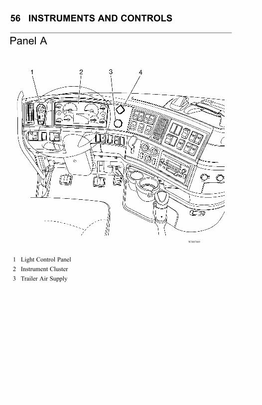
Panel A
W3007469
1 Light Control Panel2 Instrument Cluster3 Trailer Air Supply
INSTRUMENTS AND CONTROLS 57
4 Tractor Parking Brake
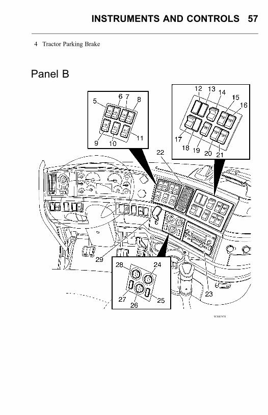
Panel B
W3007470
58 INSTRUMENTS AND CONTROLS
5. Inter-Wheel Differential Lock6. Inter-Axle Differential Lock7. VN: Idle Management IndicatorLamp (ISX ICON) or Optional Switchor Electronically Controlled Suspension(ECS) On/Off or Lift Axle #1 (Pusher)8. VN: Optional Switch or ElectronicallyControlled Suspension (ECS) Up/Down9. Auxiliary #110. VN: Auxiliary #2 or Temp-A-Start(TAS) Indicator Lamps11. VN: Auxiliary #3 or Temp-A-Start(TAS) On/Off12. Secondary Gauge Cluster13. Secondary Gauge Cluster14. Engine Brake or I-Shift Eco-Roll
15. VN: Engine Brake Mode Select (ISX)or I-Shift Hill Start Assist16. VN: 5th Wheel Touch Lock (Unlock)17. Marker Interrupt or Secondary GaugeCluster18. Optional Switch or Secondary GaugeCluster19. Traction Control20. Suspension Dump21. 5th Wheel Slide or EngineInside/Outside Air Control22. Air Vent23. Radio24. Fan Speed25. Recirculation26. Air Distribution27. AC ON/OFF28. Temperature Knob29. Trailer Hand Brake Control
INSTRUMENTS AND CONTROLS 59
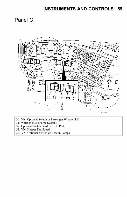
Panel C
W3007471
30. VN: Optional Switch or Passenger Window Lift31. Water in Fuel (Purge Switch)32. Optional Switch or AUX/USB Port33. VN: Sleeper Fan Speed34. VN: Optional Switch or Beacon Lamps
60 INSTRUMENTS AND CONTROLS
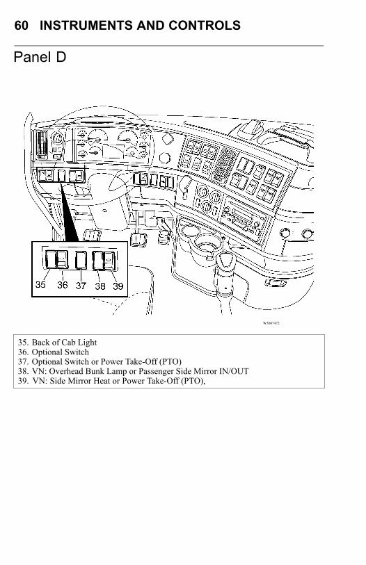
Panel D
W3007472
35. Back of Cab Light36. Optional Switch37. Optional Switch or Power Take-Off (PTO)38. VN: Overhead Bunk Lamp or Passenger Side Mirror IN/OUT39. VN: Side Mirror Heat or Power Take-Off (PTO),
INSTRUMENTS AND CONTROLS 61
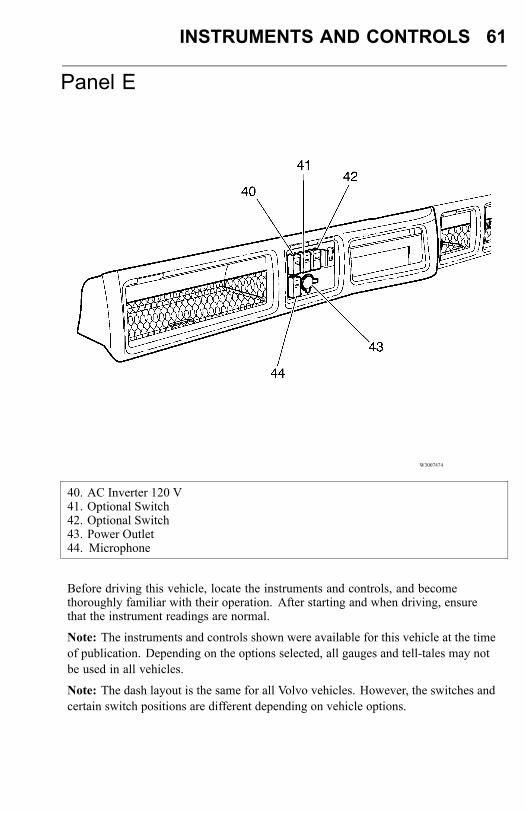
Panel E
W3007474
40. AC Inverter 120 V41. Optional Switch42. Optional Switch43. Power Outlet44. Microphone
Before driving this vehicle, locate the instruments and controls, and becomethoroughly familiar with their operation. After starting and when driving, ensurethat the instrument readings are normal.
Note: The instruments and controls shown were available for this vehicle at the timeof publication. Depending on the options selected, all gauges and tell-tales may notbe used in all vehicles.
Note: The dash layout is the same for all Volvo vehicles. However, the switches andcertain switch positions are different depending on vehicle options.
62 INSTRUMENTS AND CONTROLS
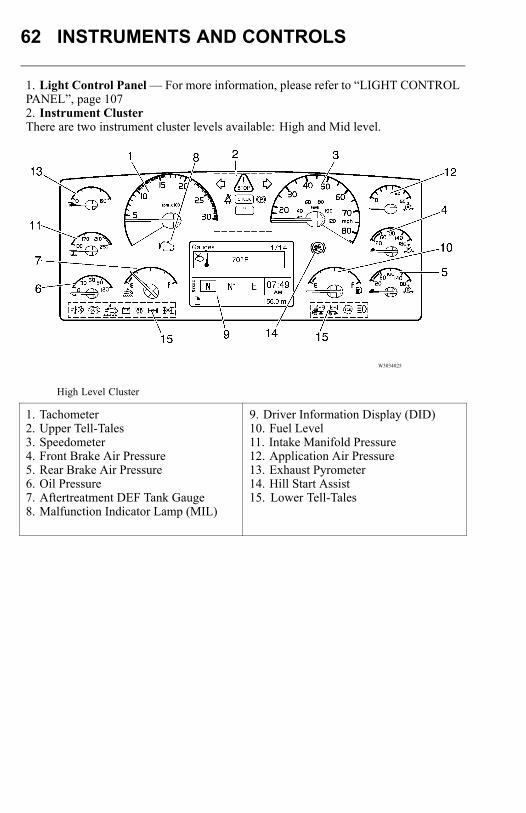
1. Light Control Panel— For more information, please refer to “LIGHT CONTROLPANEL”, page 1072. Instrument ClusterThere are two instrument cluster levels available: High and Mid level.
W3034025
High Level Cluster
1. Tachometer2. Upper Tell-Tales3. Speedometer4. Front Brake Air Pressure5. Rear Brake Air Pressure6. Oil Pressure7. Aftertreatment DEF Tank Gauge8. Malfunction Indicator Lamp (MIL)
9. Driver Information Display (DID)10. Fuel Level11. Intake Manifold Pressure12. Application Air Pressure13. Exhaust Pyrometer14. Hill Start Assist15. Lower Tell-Tales
INSTRUMENTS AND CONTROLS 63
W3034026
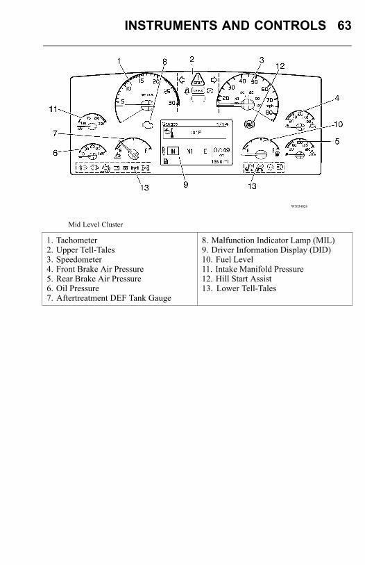
Mid Level Cluster
1. Tachometer2. Upper Tell-Tales3. Speedometer4. Front Brake Air Pressure5. Rear Brake Air Pressure6. Oil Pressure7. Aftertreatment DEF Tank Gauge
8. Malfunction Indicator Lamp (MIL)9. Driver Information Display (DID)10. Fuel Level11. Intake Manifold Pressure12. Hill Start Assist13. Lower Tell-Tales
64 INSTRUMENTS AND CONTROLS
TachometerThe tachometer has two colored fields: green and red. Use the green field for normaldriving (1000 to 1600 rpm). Use higher engine speeds for maximum engine brakeperformance. Never allow the engine to go into the red field (greater than 2200 rpm).To achieve maximum fuel economy, use the Performance Bonus Guide feature. Thisfeature helps the driver find the most efficient operating range for the engine. SeePerformance Bonus Guide for more information.
Upper Tell-TalesThe Stop, Check and Info message tell-tales are located in the upper tell-tales box onthe instrument cluster. The left and right turn signal indicators, seat belt tell-tale andparking brake tell-tale are also located in the upper tell-tales box. Refer to the DriverInformation Display manual for additional information about the message tell-tales.
SpeedometerThe speedometer is driven by the vehicle’s electronic system.
Front and Rear Brake System Air PressureGaugesThe system air gauges are connected to the front and rear circuit tanks via sensorsmounted on the pass-through wall. The two gauges should register equal air pressure.By observing the gauge pointers, the operator can detect a pressure drop if an air leakdevelops and can readily identify the circuit affected.
DANGER
Failure to observe these precautionscan result in the loss of brakingperformance. This can lead to a vehicleaccident, which can result in personalinjury or death.
INSTRUMENTS AND CONTROLS 65
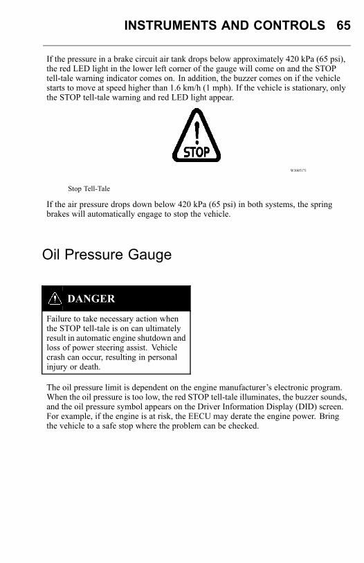
If the pressure in a brake circuit air tank drops below approximately 420 kPa (65 psi),the red LED light in the lower left corner of the gauge will come on and the STOPtell-tale warning indicator comes on. In addition, the buzzer comes on if the vehiclestarts to move at speed higher than 1.6 km/h (1 mph). If the vehicle is stationary, onlythe STOP tell-tale warning and red LED light appear.
W3005171
Stop Tell-Tale
If the air pressure drops down below 420 kPa (65 psi) in both systems, the springbrakes will automatically engage to stop the vehicle.
Oil Pressure Gauge
DANGER
Failure to take necessary action whenthe STOP tell-tale is on can ultimatelyresult in automatic engine shutdown andloss of power steering assist. Vehiclecrash can occur, resulting in personalinjury or death.
The oil pressure limit is dependent on the engine manufacturer’s electronic program.When the oil pressure is too low, the red STOP tell-tale illuminates, the buzzer sounds,and the oil pressure symbol appears on the Driver Information Display (DID) screen.For example, if the engine is at risk, the EECU may derate the engine power. Bringthe vehicle to a safe stop where the problem can be checked.

66 INSTRUMENTS AND CONTROLS
W3005171
Stop Tell-Tale
W3003613
Oil Pressure Symbol
Note: The engine will shut down within 30 seconds from when the red STOP tell-talecomes on. Pull off the road as soon as possible without creating a safety hazard.
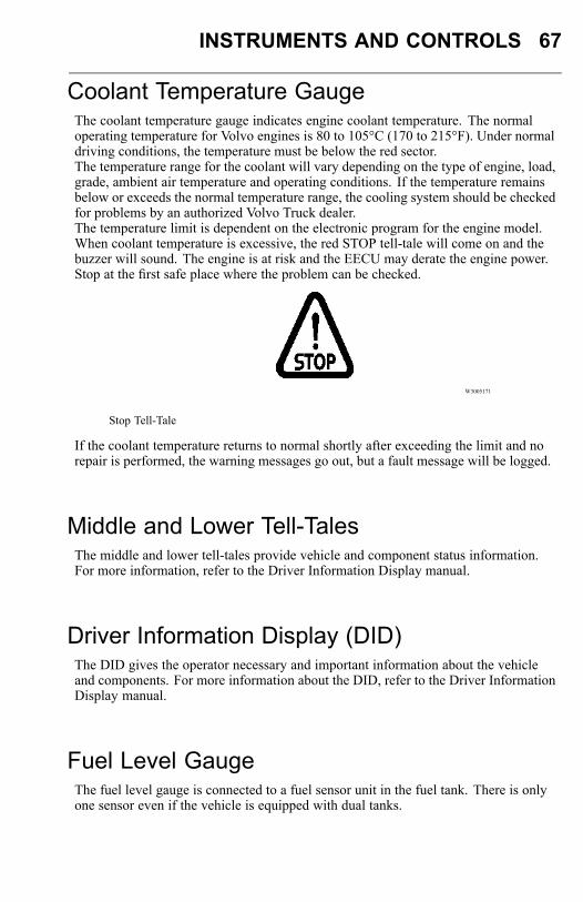
INSTRUMENTS AND CONTROLS 67
Coolant Temperature GaugeThe coolant temperature gauge indicates engine coolant temperature. The normaloperating temperature for Volvo engines is 80 to 105°C (170 to 215°F). Under normaldriving conditions, the temperature must be below the red sector.The temperature range for the coolant will vary depending on the type of engine, load,grade, ambient air temperature and operating conditions. If the temperature remainsbelow or exceeds the normal temperature range, the cooling system should be checkedfor problems by an authorized Volvo Truck dealer.The temperature limit is dependent on the electronic program for the engine model.When coolant temperature is excessive, the red STOP tell-tale will come on and thebuzzer will sound. The engine is at risk and the EECU may derate the engine power.Stop at the first safe place where the problem can be checked.
W3005171
Stop Tell-Tale
If the coolant temperature returns to normal shortly after exceeding the limit and norepair is performed, the warning messages go out, but a fault message will be logged.
Middle and Lower Tell-TalesThe middle and lower tell-tales provide vehicle and component status information.For more information, refer to the Driver Information Display manual.
Driver Information Display (DID)The DID gives the operator necessary and important information about the vehicleand components. For more information about the DID, refer to the Driver InformationDisplay manual.
Fuel Level GaugeThe fuel level gauge is connected to a fuel sensor unit in the fuel tank. There is onlyone sensor even if the vehicle is equipped with dual tanks.
68 INSTRUMENTS AND CONTROLS
Intake Manifold Pressure Gauge (High LevelCluster Only)The intake manifold pressure gauge indicates intake manifold pressure to the engine.The pressure generated by the intake manifold pressure should be the same at a givenengine temperature, speed and load. Intake manifold pressure will vary for differentengines and vehicle models. By monitoring the gauge, the operator can avoid engineproblems.
Application Air Pressure Gauge (High LevelCluster Only)Air gauges are connected to the air brake system via sensors. They will indicate thebrake application pressure from either the front, rear or trailer circuit pressure. Thegauge will not register air pressure until the foot brake pedal is depressed or the trailerhand brake is applied.
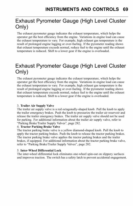
INSTRUMENTS AND CONTROLS 69
Exhaust Pyrometer Gauge (High Level ClusterOnly)The exhaust pyrometer gauge indicates the exhaust temperature, which helps theoperator get the best efficiency from the engine. Variations in engine load can causethe exhaust temperature to vary. For example, high exhaust gas temperature is theresult of prolonged engine lugging or over-fueling. If the pyrometer reading showsthat exhaust temperature exceeds normal, reduce fuel to the engine until the exhausttemperature is reduced. Shift to a lower gear if the engine is overloaded.
Exhaust Pyrometer Gauge (High Level ClusterOnly)The exhaust pyrometer gauge indicates the exhaust temperature, which helps theoperator get the best efficiency from the engine. Variations in engine load can causethe exhaust temperature to vary. For example, high exhaust gas temperature is theresult of prolonged engine lugging or over-fueling. If the pyrometer reading showsthat exhaust temperature exceeds normal, reduce fuel to the engine until the exhausttemperature is reduced. Shift to a lower gear if the engine is overloaded.
3. Trailer Air Supply ValveThe trailer air supply valve is a red octagonally-shaped knob. Pull the knob to applythe trailer emergency brakes. Push the knob to pressurize the trailer air reservoir andrelease the trailer emergency brakes. The trailer air supply valve should not be usedfor parking. For additional information about the trailer air supply valve, refer to“Parking Brake/Trailer Supply Valves”, page 282.4. Tractor Parking Brake ValveThe tractor parking brake valve is a yellow diamond-shaped knob. Pull the knob toapply the tractor parking brakes. Push the knob to release the tractor parking brakes.The tractor parking brake valve applies the tractor parking brakes and the trailerbrakes, if equipped. For additional information about the tractor parking brake valve,refer to “Parking Brake/Trailer Supply Valves”, page 282.
5. Inter-Wheel Differential LockThe inter-wheel differential lock eliminates one-wheel spin-out on slippery surfacesand improves traction. The switch has a safety latch to prevent accidental engagement.
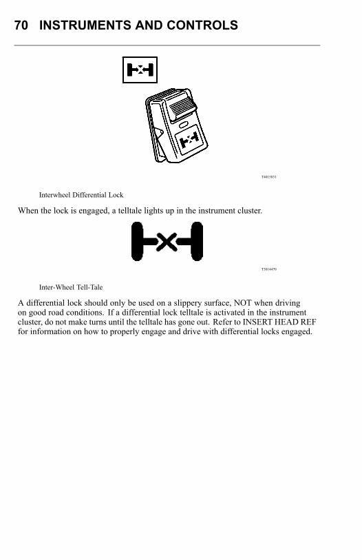
70 INSTRUMENTS AND CONTROLS
T4015831
Interwheel Differential Lock
When the lock is engaged, a telltale lights up in the instrument cluster.
T3014470
Inter-Wheel Tell-Tale
A differential lock should only be used on a slippery surface, NOT when drivingon good road conditions. If a differential lock telltale is activated in the instrumentcluster, do not make turns until the telltale has gone out. Refer to INSERT HEAD REFfor information on how to properly engage and drive with differential locks engaged.
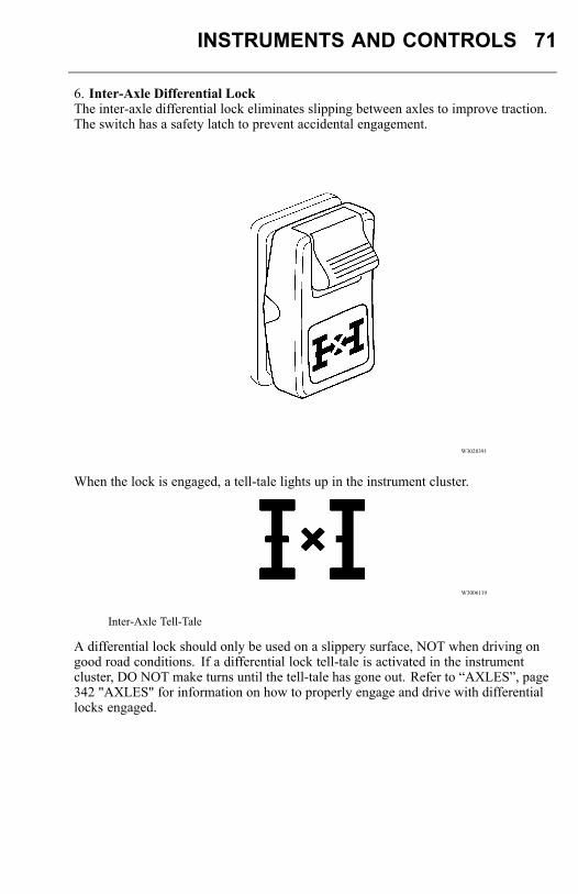
INSTRUMENTS AND CONTROLS 71
6. Inter-Axle Differential LockThe inter-axle differential lock eliminates slipping between axles to improve traction.The switch has a safety latch to prevent accidental engagement.
W3028391
When the lock is engaged, a tell-tale lights up in the instrument cluster.
W3006119
Inter-Axle Tell-Tale
A differential lock should only be used on a slippery surface, NOT when driving ongood road conditions. If a differential lock tell-tale is activated in the instrumentcluster, DO NOT make turns until the tell-tale has gone out. Refer to “AXLES”, page342 "AXLES" for information on how to properly engage and drive with differentiallocks engaged.
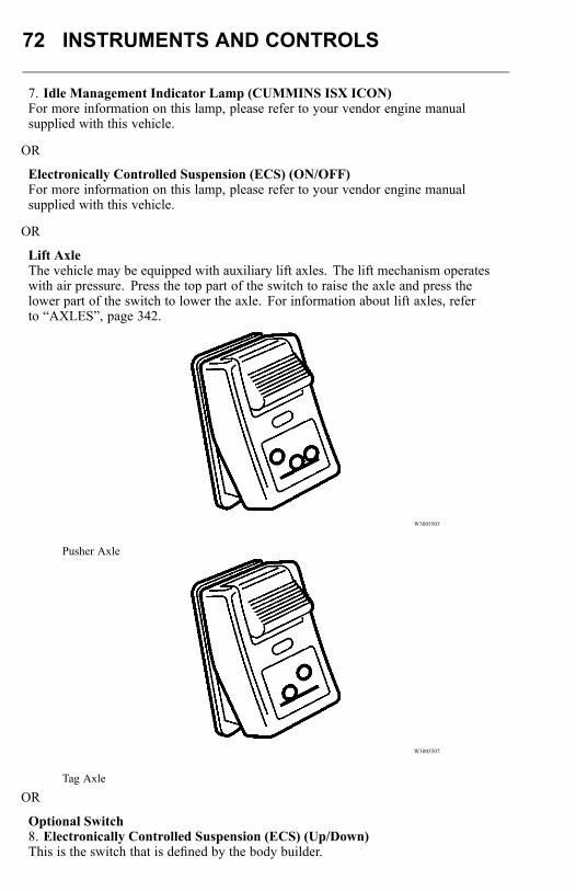
72 INSTRUMENTS AND CONTROLS
7. Idle Management Indicator Lamp (CUMMINS ISX ICON)For more information on this lamp, please refer to your vendor engine manualsupplied with this vehicle.
OR
Electronically Controlled Suspension (ECS) (ON/OFF)For more information on this lamp, please refer to your vendor engine manualsupplied with this vehicle.
OR
Lift AxleThe vehicle may be equipped with auxiliary lift axles. The lift mechanism operateswith air pressure. Press the top part of the switch to raise the axle and press thelower part of the switch to lower the axle. For information about lift axles, referto “AXLES”, page 342.
W3005503
Pusher Axle
W3005507
Tag Axle
OR
Optional Switch8. Electronically Controlled Suspension (ECS) (Up/Down)This is the switch that is defined by the body builder.

INSTRUMENTS AND CONTROLS 73
OR
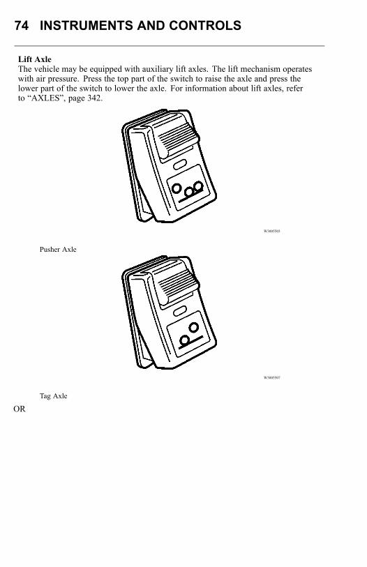
74 INSTRUMENTS AND CONTROLS
Lift AxleThe vehicle may be equipped with auxiliary lift axles. The lift mechanism operateswith air pressure. Press the top part of the switch to raise the axle and press thelower part of the switch to lower the axle. For information about lift axles, referto “AXLES”, page 342.
W3005503
Pusher Axle
W3005507
Tag Axle
OR
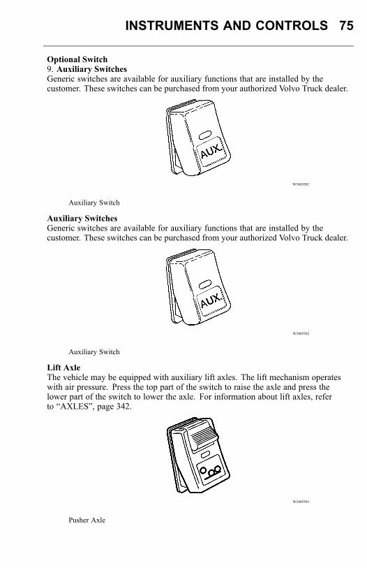
INSTRUMENTS AND CONTROLS 75
Optional Switch9. Auxiliary SwitchesGeneric switches are available for auxiliary functions that are installed by thecustomer. These switches can be purchased from your authorized Volvo Truck dealer.
W3005502
Auxiliary Switch
Auxiliary SwitchesGeneric switches are available for auxiliary functions that are installed by thecustomer. These switches can be purchased from your authorized Volvo Truck dealer.
W3005502
Auxiliary Switch
Lift AxleThe vehicle may be equipped with auxiliary lift axles. The lift mechanism operateswith air pressure. Press the top part of the switch to raise the axle and press thelower part of the switch to lower the axle. For information about lift axles, referto “AXLES”, page 342.
W3005503
Pusher Axle
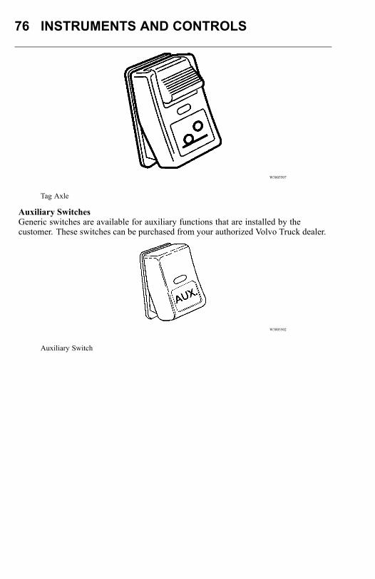
76 INSTRUMENTS AND CONTROLS
W3005507
Tag Axle
Auxiliary SwitchesGeneric switches are available for auxiliary functions that are installed by thecustomer. These switches can be purchased from your authorized Volvo Truck dealer.
W3005502
Auxiliary Switch
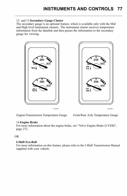
INSTRUMENTS AND CONTROLS 77
12. and 13.Secondary Gauge ClusterThe secondary gauge is an optional feature, which is available only with the Midand High level instrument clusters. The instrument cluster receives temperatureinformation from the datalink and then passes the information to the secondarygauge for viewing.
W3006081 W3006082
Engine/Transmission Temperature Gauge Front/Rear Axle Temperature Gauge
14.Engine BrakeFor more information about the engine brake, see “Volvo Engine Brake (I-VEB)”,page 272.
OR
I-Shift Eco-RollFor more information on this feature, please refer to the I-Shift Transmission Manualsupplied with your vehicle.
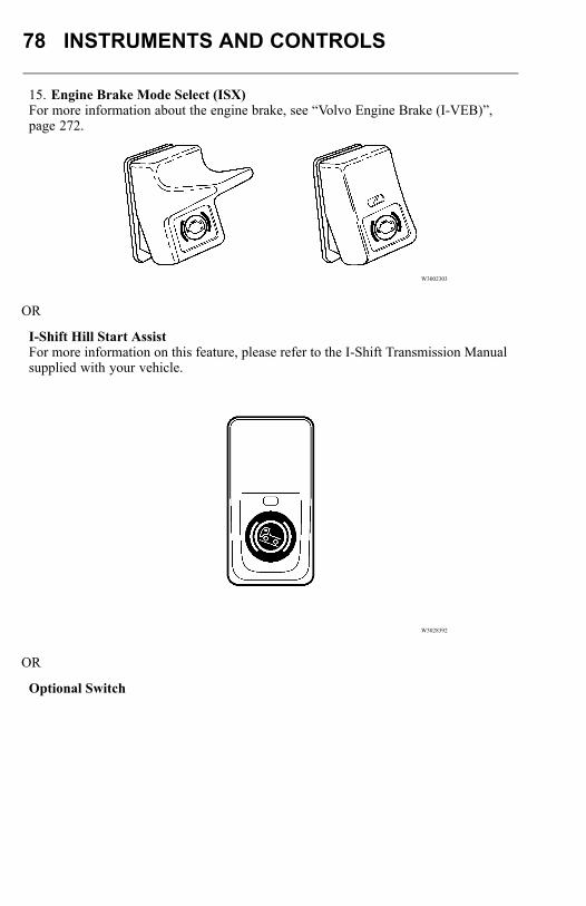
78 INSTRUMENTS AND CONTROLS
15. Engine Brake Mode Select (ISX)For more information about the engine brake, see “Volvo Engine Brake (I-VEB)”,page 272.
W3002303
OR
I-Shift Hill Start AssistFor more information on this feature, please refer to the I-Shift Transmission Manualsupplied with your vehicle.
W3028392
OR
Optional Switch
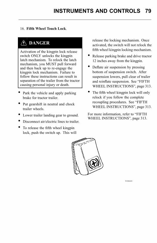
INSTRUMENTS AND CONTROLS 79
16. Fifth Wheel Touch Lock.
DANGER
Activation of the kingpin lock releaseswitch ONLY unlocks the kingpinlatch mechanism. To relock the latchmechanism, you MUST pull forwardand then back up to re-engage thekingpin lock mechanism. Failure tofollow these instructions can result inseparation of the trailer from the tractorcausing personal injury or death.
• Park the vehicle and apply parkingbrake for tractor trailer.
• Put gearshift in neutral and chocktrailer wheels.
• Lower trailer landing gear to ground.
• Disconnect air/electric lines to trailer.
• To release the fifth wheel kingpinlock, push the switch up. This will
release the locking mechanism. Onceactivated, the switch will not relock thefifth wheel kingpin locking mechanism.
• Release parking brake and drive tractor12 inches away from the kingpin.
• Deflate air suspension by pressingbottom of suspension switch. Aftersuspension lowers, pull clear of trailerand reinflate suspension. See “FIFTHWHEEL INSTRUCTIONS”, page 313.
• The fifth wheel kingpin lock will onlyrelock if you follow the completerecoupling procedures. See “FIFTHWHEEL INSTRUCTIONS”, page 313.
For more information, refer to “FIFTHWHEEL INSTRUCTIONS”, page 313.
W3004428

80 INSTRUMENTS AND CONTROLS
17. Marker Interrupt SwitchThis switch interrupts power to the marker lights when held down. When released, itsprings back to the ON position and returns power to the marker lights.
W3001352
Marker Interrupt Switch
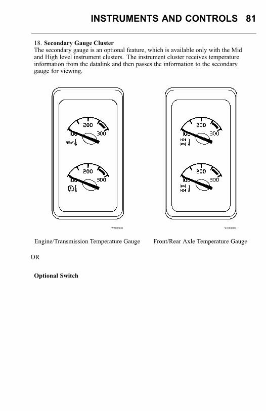
INSTRUMENTS AND CONTROLS 81
18. Secondary Gauge ClusterThe secondary gauge is an optional feature, which is available only with the Midand High level instrument clusters. The instrument cluster receives temperatureinformation from the datalink and then passes the information to the secondarygauge for viewing.
W3006081 W3006082
Engine/Transmission Temperature Gauge Front/Rear Axle Temperature Gauge
OR
Optional Switch
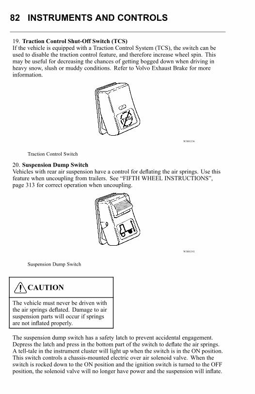
82 INSTRUMENTS AND CONTROLS
19. Traction Control Shut-Off Switch (TCS)If the vehicle is equipped with a Traction Control System (TCS), the switch can beused to disable the traction control feature, and therefore increase wheel spin. Thismay be useful for decreasing the chances of getting bogged down when driving inheavy snow, slush or muddy conditions. Refer to Volvo Exhaust Brake for moreinformation.
W3001336
Traction Control Switch
20. Suspension Dump SwitchVehicles with rear air suspension have a control for deflating the air springs. Use thisfeature when uncoupling from trailers. See “FIFTH WHEEL INSTRUCTIONS”,page 313 for correct operation when uncoupling.
W3001341
Suspension Dump Switch
CAUTION
The vehicle must never be driven withthe air springs deflated. Damage to airsuspension parts will occur if springsare not inflated properly.
The suspension dump switch has a safety latch to prevent accidental engagement.Depress the latch and press in the bottom part of the switch to deflate the air springs.A tell-tale in the instrument cluster will light up when the switch is in the ON position.This switch controls a chassis-mounted electric over air solenoid valve. When theswitch is rocked down to the ON position and the ignition switch is turned to the OFFposition, the solenoid valve will no longer have power and the suspension will inflate.
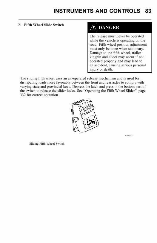
INSTRUMENTS AND CONTROLS 83
21. Fifth Wheel Slide SwitchDANGER
The release must never be operatedwhile the vehicle is operating on theroad. Fifth wheel position adjustmentmust only be done when stationary.Damage to the fifth wheel, trailerkingpin and slider may occur if notoperated properly and may lead toan accident, causing serious personalinjury or death.
The sliding fifth wheel uses an air-operated release mechanism and is used fordistributing loads more favorably between the front and rear axles to comply withvarying state and provincial laws. Depress the latch and press in the bottom part ofthe switch to release the slider locks. See “Operating the Fifth Wheel Slider”, page332 for correct operation.
W3001346
Sliding Fifth Wheel Switch
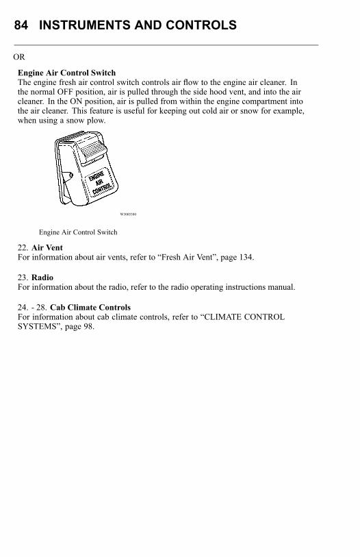
84 INSTRUMENTS AND CONTROLS
OR
Engine Air Control SwitchThe engine fresh air control switch controls air flow to the engine air cleaner. Inthe normal OFF position, air is pulled through the side hood vent, and into the aircleaner. In the ON position, air is pulled from within the engine compartment intothe air cleaner. This feature is useful for keeping out cold air or snow for example,when using a snow plow.
W3005380
Engine Air Control Switch
22. Air VentFor information about air vents, refer to “Fresh Air Vent”, page 134.
23. RadioFor information about the radio, refer to the radio operating instructions manual.
24. - 28. Cab Climate ControlsFor information about cab climate controls, refer to “CLIMATE CONTROLSYSTEMS”, page 98.
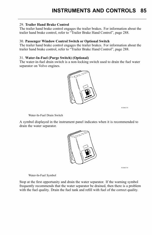
INSTRUMENTS AND CONTROLS 85
29. Trailer Hand Brake ControlThe trailer hand brake control engages the trailer brakes. For information about thetrailer hand brake control, refer to “Trailer Brake Hand Control”, page 288.
30. Passenger Window Control Switch or Optional SwitchThe trailer hand brake control engages the trailer brakes. For information about thetrailer hand brake control, refer to “Trailer Brake Hand Control”, page 288.
31. Water-In-Fuel (Purge Switch) (Optional)The water-in-fuel drain switch is a non-locking switch used to drain the fuel waterseparator on Volvo engines.
W3005378
Water-In-Fuel Drain Switch
A symbol displayed in the instrument panel indicates when it is recommended todrain the water separator.
W3005378
Water-In-Fuel Symbol
Stop at the first opportunity and drain the water separator. If the warning symbolfrequently recommends that the water separator be drained, then there is a problemwith the fuel quality. Drain the fuel tank and refill with fuel of the correct quality.
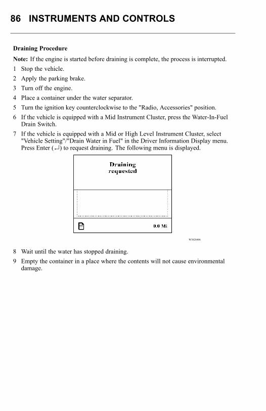
86 INSTRUMENTS AND CONTROLS
Draining Procedure
Note: If the engine is started before draining is complete, the process is interrupted.1 Stop the vehicle.2 Apply the parking brake.3 Turn off the engine.4 Place a container under the water separator.5 Turn the ignition key counterclockwise to the "Radio, Accessories" position.6 If the vehicle is equipped with a Mid Instrument Cluster, press the Water-In-Fuel
Drain Switch.7 If the vehicle is equipped with a Mid or High Level Instrument Cluster, select
"Vehicle Setting"/"Drain Water in Fuel" in the Driver Information Display menu.Press Enter (↵) to request draining. The following menu is displayed.
W3028406
8 Wait until the water has stopped draining.9 Empty the container in a place where the contents will not cause environmental
damage.
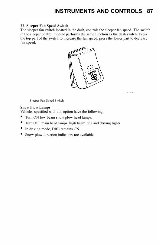
INSTRUMENTS AND CONTROLS 87
33. Sleeper Fan Speed SwitchThe sleeper fan switch located in the dash, controls the sleeper fan speed. The switchin the sleeper control module performs the same function as the dash switch. Pressthe top part of the switch to increase the fan speed, press the lower part to decreasefan speed.
W3005382
Sleeper Fan Speed Switch
Snow Plow LampsVehicles specified with this option have the following:• Turn ON low beam snow plow head lamps.• Turn OFF main head lamps, high beam, fog and driving lights.• In driving mode, DRL remains ON.• Snow plow direction indicators are available.
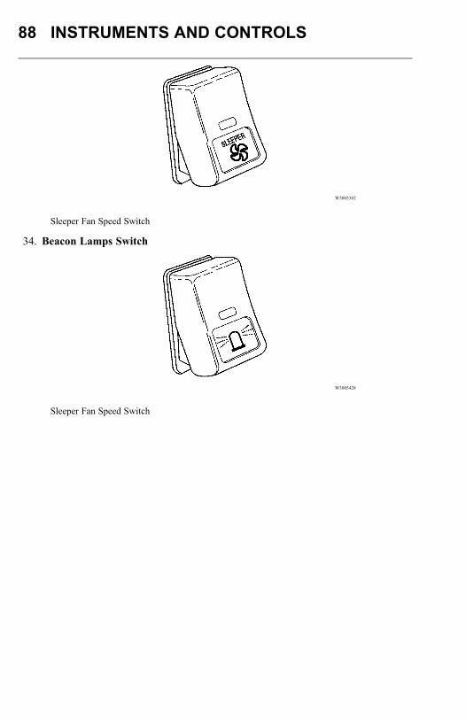
88 INSTRUMENTS AND CONTROLS
W3005382
Sleeper Fan Speed Switch
34. Beacon Lamps Switch
W3005428
Sleeper Fan Speed Switch
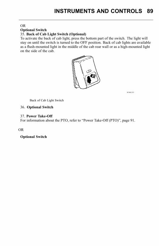
INSTRUMENTS AND CONTROLS 89
OROptional Switch35. Back of Cab Light Switch (Optional)To activate the back of cab light, press the bottom part of the switch. The light willstay on until the switch is turned to the OFF position. Back of cab lights are availableas a flush-mounted light in the middle of the cab rear wall or as a high-mounted lighton the side of the cab.
W3001355
Back of Cab Light Switch
36. Optional Switch
37. Power Take-OffFor information about the PTO, refer to “Power Take-Off (PTO)”, page 91.
OR
Optional Switch
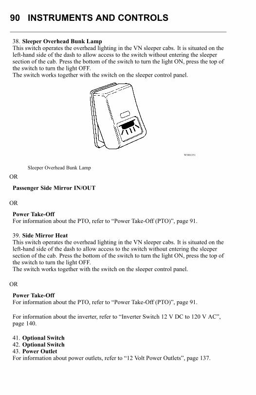
90 INSTRUMENTS AND CONTROLS
38. Sleeper Overhead Bunk LampThis switch operates the overhead lighting in the VN sleeper cabs. It is situated on theleft-hand side of the dash to allow access to the switch without entering the sleepersection of the cab. Press the bottom of the switch to turn the light ON, press the top ofthe switch to turn the light OFF.The switch works together with the switch on the sleeper control panel.
W3001351
Sleeper Overhead Bunk Lamp
OR
Passenger Side Mirror IN/OUT
OR
Power Take-OffFor information about the PTO, refer to “Power Take-Off (PTO)”, page 91.
39. Side Mirror HeatThis switch operates the overhead lighting in the VN sleeper cabs. It is situated on theleft-hand side of the dash to allow access to the switch without entering the sleepersection of the cab. Press the bottom of the switch to turn the light ON, press the top ofthe switch to turn the light OFF.The switch works together with the switch on the sleeper control panel.
OR
Power Take-OffFor information about the PTO, refer to “Power Take-Off (PTO)”, page 91.
For information about the inverter, refer to “Inverter Switch 12 V DC to 120 V AC”,page 140.
41. Optional Switch42. Optional Switch43. Power OutletFor information about power outlets, refer to “12 Volt Power Outlets”, page 137.
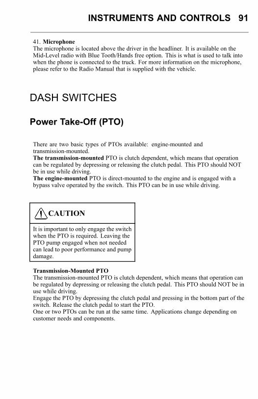
INSTRUMENTS AND CONTROLS 91
41. MicrophoneThe microphone is located above the driver in the headliner. It is available on theMid-Level radio with Blue Tooth/Hands free option. This is what is used to talk intowhen the phone is connected to the truck. For more information on the microphone,please refer to the Radio Manual that is supplied with the vehicle.
DASH SWITCHES
Power Take-Off (PTO)
There are two basic types of PTOs available: engine-mounted andtransmission-mounted.The transmission-mounted PTO is clutch dependent, which means that operationcan be regulated by depressing or releasing the clutch pedal. This PTO should NOTbe in use while driving.The engine-mounted PTO is direct-mounted to the engine and is engaged with abypass valve operated by the switch. This PTO can be in use while driving.
CAUTION
It is important to only engage the switchwhen the PTO is required. Leaving thePTO pump engaged when not neededcan lead to poor performance and pumpdamage.
Transmission-Mounted PTOThe transmission-mounted PTO is clutch dependent, which means that operation canbe regulated by depressing or releasing the clutch pedal. This PTO should NOT be inuse while driving.Engage the PTO by depressing the clutch pedal and pressing in the bottom part of theswitch. Release the clutch pedal to start the PTO.One or two PTOs can be run at the same time. Applications change depending oncustomer needs and components.
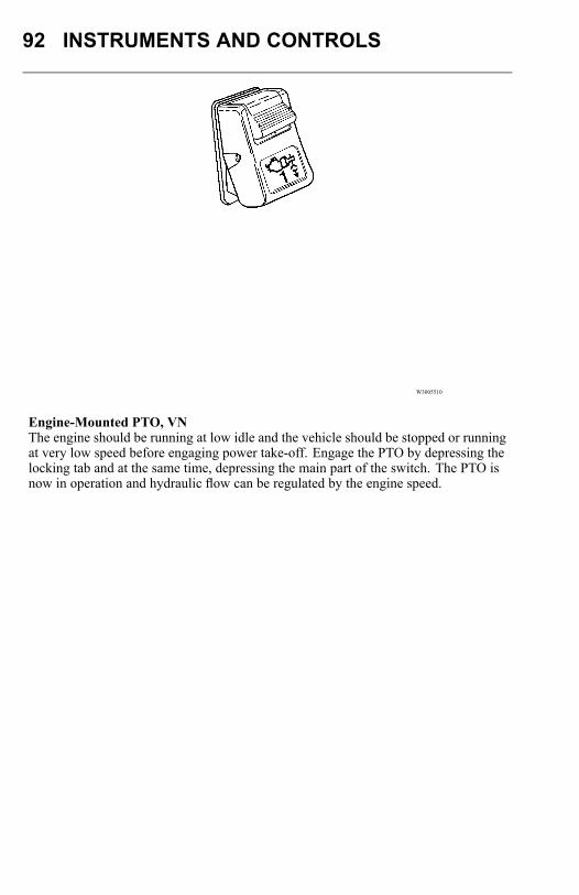
92 INSTRUMENTS AND CONTROLS
W3005510
Engine-Mounted PTO, VNThe engine should be running at low idle and the vehicle should be stopped or runningat very low speed before engaging power take-off. Engage the PTO by depressing thelocking tab and at the same time, depressing the main part of the switch. The PTO isnow in operation and hydraulic flow can be regulated by the engine speed.
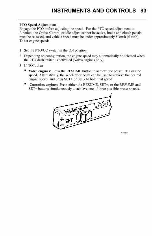
INSTRUMENTS AND CONTROLS 93
PTO Speed AdjustmentEngage the PTO before adjusting the speed. For the PTO speed adjustment tofunction, the Cruise Control or idle adjust cannot be active, brake and clutch pedalsmust be released, and vehicle speed must be under approximately 8 km/h (5 mph).To set engine speed:
1 Set the PTO/CC switch in the ON position.2 Depending on configuration, the engine speed may automatically be selected when
the PTO dash switch is activated (Volvo engines only).3 If NOT, then• Volvo engines: Press the RESUME button to achieve the preset PTO engine
speed. Alternatively, the accelerator pedal can be used to achieve the desiredengine speed, and press SET+ or SET- to hold that speed
• .Cummins engines: Press either the RESUME, SET+, or the RESUME andSET+ buttons simultaneously to achieve one of three possible preset speeds.
W3002499
94 INSTRUMENTS AND CONTROLS
To increase/decrease engine speed:
1 Volvo engines: Press and release the SET+ or SET- toggle switch toincrease/decrease speed in increments (increment size depends on programmedvalue).
2 Cummins engines: Press and hold the SET+ or SET- toggle switch toincrease/decrease speed. When the switch is released, the engine speed sets atcurrent speed.
To deactivate PTO speed function. Set the PTO/CC switch to the OFF position.or2. Depress the service brake pedal.or3. Depress the clutch pedal (Programmable).or4. Increase vehicle speed above PTO working range (typically 8 km/h [5 mph]).
Engine Brake
DANGER
When operating your tractor bobtail(without a trailer) or on slippery roads,the engine brake switch must be in theOFF position. Failure to follow theseinstructions can result in loss of vehiclecontrol, serious personal injury or death.
DANGER
A vehicle speed retarding device is notintended to replace the service brakesystem on your vehicle nor intended tobring your vehicle to a stop. A vehiclespeed retarding device is only intendedto retard the speed of your vehicle undercertain conditions.Using the retarding device as a brakecould result in loss of vehicle controland personal injury or death.
Note: It is normal for a slight delay to occur in the application of a vehicle speedretarding device. When using a device of this type, be sure to think ahead and analyzeconditions in order to use the device properly.Several types of engine brakes can be installed or are standard on certain engines. Allare used to reduce wear on the vehicle brake linings.
Several types of engine brakes can be installed or are standard on certain engines. Allare used to reduce wear on the vehicle brake linings.
Volvo Variable Geometry Turbo Brake VNThe variable geometry turbo brake is standard equipment on the Volvo 11F and 13Fengines. Software is used to close the variable geometry turbocharger, creatingretardation. The switch for exhaust brake has two positions: ON/OFF.
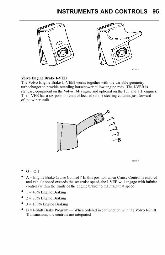
INSTRUMENTS AND CONTROLS 95
W3005433
Volvo Engine Brake I-VEBThe Volvo Engine Brake (I-VEB) works together with the variable geometryturbocharger to provide retarding horsepower at low engine rpm. The I-VEB isstandard equipment on the Volvo 16F engine and optional on the 13F and 11F engines.The I-VEB has a six position control located on the steering column, just forwardof the wiper stalk.
T5012243
• O = Off• A = Engine Brake Cruise Control ? In this position when Cruise Control is enabled
and vehicle speed exceeds the set cruise speed, the I-VEB will engage with infinitecontrol (within the limits of the engine brake) to maintain that speed
• 1 = 40% Engine Braking• 2 = 70% Engine Braking• 3 = 100% Engine Braking• B = I-Shift Brake Program —When ordered in conjunction with the Volvo I-Shift
Transmission, the controls are integrated
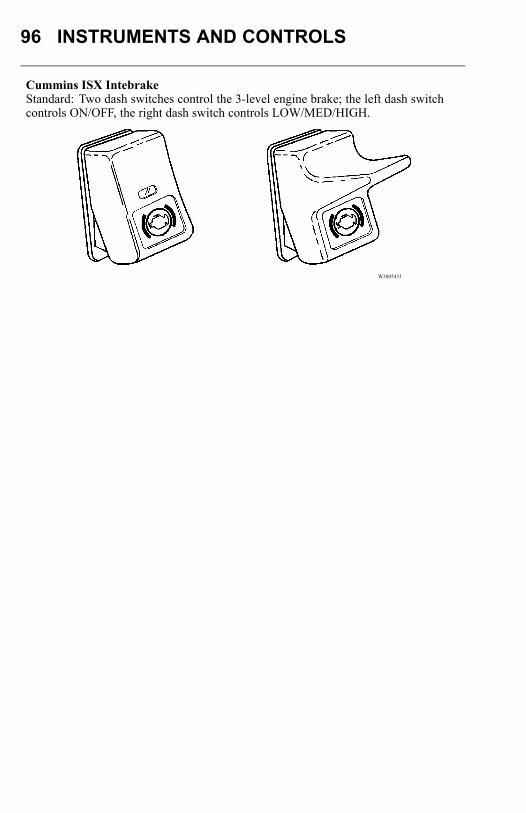
96 INSTRUMENTS AND CONTROLS
Cummins ISX IntebrakeStandard: Two dash switches control the 3-level engine brake; the left dash switchcontrols ON/OFF, the right dash switch controls LOW/MED/HIGH.
W3005433
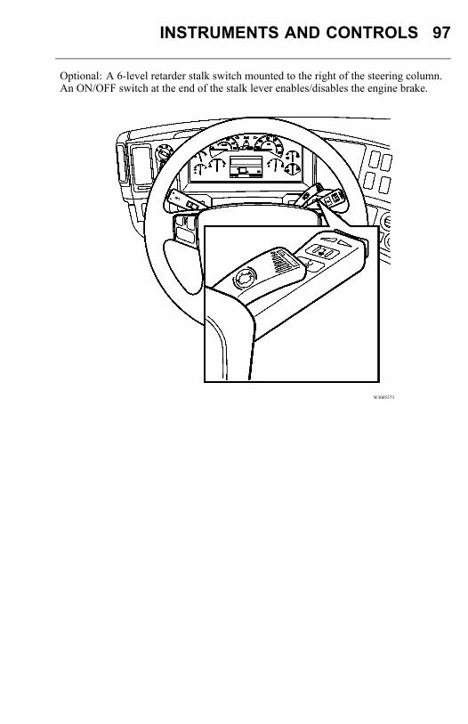
INSTRUMENTS AND CONTROLS 97
Optional: A 6-level retarder stalk switch mounted to the right of the steering column.An ON/OFF switch at the end of the stalk lever enables/disables the engine brake.
W3005373
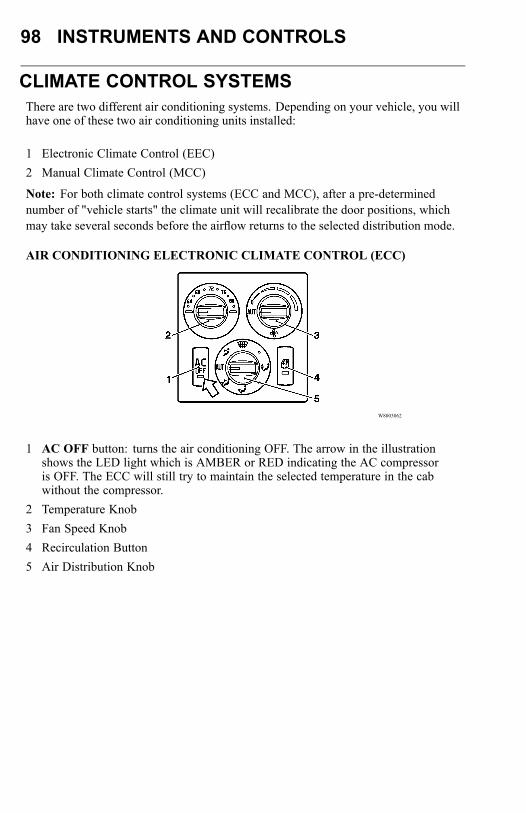
98 INSTRUMENTS AND CONTROLS
CLIMATE CONTROL SYSTEMSThere are two different air conditioning systems. Depending on your vehicle, you willhave one of these two air conditioning units installed:
1 Electronic Climate Control (EEC)2 Manual Climate Control (MCC)
Note: For both climate control systems (ECC and MCC), after a pre-determinednumber of "vehicle starts" the climate unit will recalibrate the door positions, whichmay take several seconds before the airflow returns to the selected distribution mode.
AIR CONDITIONING ELECTRONIC CLIMATE CONTROL (ECC)
W8003062
1 AC OFF button: turns the air conditioning OFF. The arrow in the illustrationshows the LED light which is AMBER or RED indicating the AC compressoris OFF. The ECC will still try to maintain the selected temperature in the cabwithout the compressor.
2 Temperature Knob3 Fan Speed Knob4 Recirculation Button5 Air Distribution Knob
INSTRUMENTS AND CONTROLS 99
RecirculationPress recirculation to circulate the air in the cab. Only a small amount of air is takendirectly from outside.The light in the button comes on when the button is pressed for air recirculation.
Temperature Control Settings ECCMaximum Cold SettingThe temperature knob should be set to the far left. The fan speed knob should be set toAUTO and the air distribution knob should be on AUTO.
Maximum Heat SettingThe temperature knob should be set to the far right. The fan speed knob should be setto AUTO and the air distribution knob should be on AUTO.
Normal SettingWhen the temperature control is set to any temperature between 18°C and 27°C (64°Fand 80°F), the ECC automatically adjusts itself close to the selected temperature,similar to a thermostat
Fan SpeedThe fan speeds are 1 through 4. The fan will not operate when "0" is selected, but airwill flow when set to fresh air mode due to ram air effect when the truck is moving.• The ECC automatically circulates air at fan speed 4 when there is a big difference
between the selected temperature and the temperature measured by the in-cabsensor. However, as the temperature in the cab gets closer to the selectedtemperature, the fan speed begins to slow down.
• If maximum cold or maximum heat are selected, the ECC automatically circulatesair at fan speed 4 when AUT is selected. At any other selected fan speed the systemadjusts and conforms to the chosen speed.
100 INSTRUMENTS AND CONTROLS
Mist and Ice RemovalDANGER
DO NOT attempt to drive with thewindshield covered by mist, or fog orfrost. The visibility is reduced, whichcould lead to an accident causing severepersonal injury or death.
1 Turn knob to defrost.2 Rotate the temperature knob to add heat as necessary.3 Set the fan speed knob to maximum (the extreme right).Use these instructions to keep the windshield clear at all times. Maximum heat outputfor fast defrosting can only happen after the engine has reached operating temperature.While driving in extreme cold, adding heat to the windshield may change driftingsnow to ice, in this case, setting the air distribution to floor and/or panel only mayallow the drifting snow to be brushed off by the windshield wiper. Clean the inside ofthe window using normal window cleaner in order to minimize the risk of misting.Clean more often if a passenger smokes in the cab.
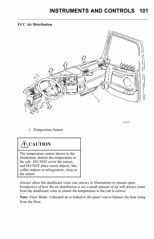
INSTRUMENTS AND CONTROLS 101
ECC Air Distribution
W8003067
1 Temperature Sensor
CAUTION
The temperature sensor shown in theillustration, detects the temperature inthe cab. DO NOT cover the sensor,and DO NOT place warm objects, likecoffee makers or refrigerators, close tothe sensor.
Always allow the dashboard vents (see arrows in illustration) to remain open.Irrespective of how the air distribution is set, a small amount of air will always comefrom the dashboard vents to ensure the temperature in the cab is correct.
Note: Floor Mode: Unheated air is leaked to the panel vent to balance the heat risingfrom the floor.
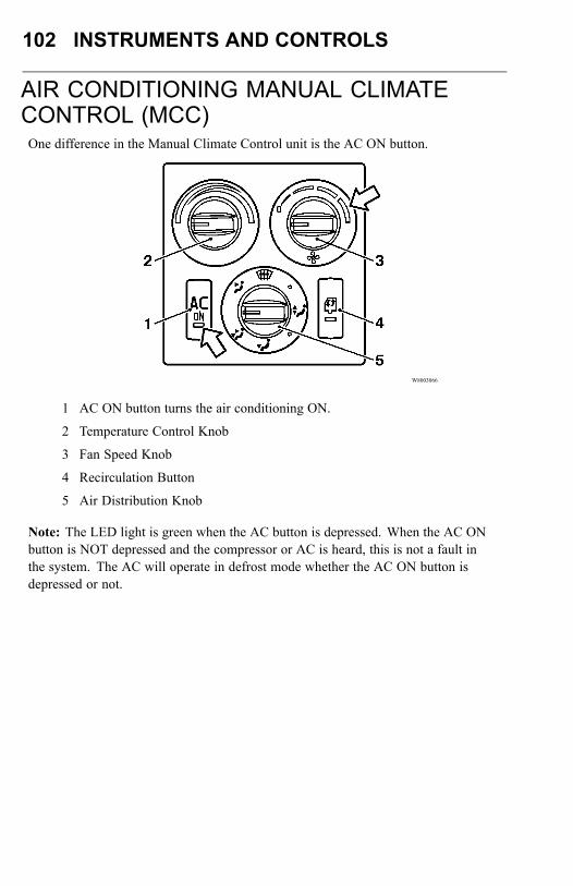
102 INSTRUMENTS AND CONTROLS
AIR CONDITIONING MANUAL CLIMATECONTROL (MCC)One difference in the Manual Climate Control unit is the AC ON button.
W8003066
1 AC ON button turns the air conditioning ON.
2 Temperature Control Knob
3 Fan Speed Knob
4 Recirculation Button
5 Air Distribution Knob
Note: The LED light is green when the AC button is depressed. When the AC ONbutton is NOT depressed and the compressor or AC is heard, this is not a fault inthe system. The AC will operate in defrost mode whether the AC ON button isdepressed or not.
INSTRUMENTS AND CONTROLS 103
Recirculation
Press recirculation to circulate the air in the cab. Only a small amount of air is takendirectly from outside.The light in the button comes on when the button is pressed for air recirculation.
Temperature Control Settings MCC
Move the knob to the blue bar for cool air to circulate in the cab, and to the red barfor warm to hot air to circulate in the cab. Select the desired fan speed starting from1 to 4. "0" is not a fan speed.
Mist and Ice Removal DANGER
DO NOT attempt to drive with thewindshield covered by mist, or fog orfrost. The visibility is reduced, whichcould lead to an accident causing severepersonal injury or death.
1 Turn knob to defrost.2 Rotate the temperature knob to add heat as necessary.3 Set the fan to maximum (the extreme right).
Use these instructions to keep the windshield clear at all times. Maximum heat outputfor fast defrosting can only happen after the engine has reached operating temperature.While driving in extreme cold, adding heat to the windshield may change driftingsnow to ice, in this case, setting the air distribution to floor and/or panel only mayallow the drifting snow to be brushed off by the windshield wiper.Clean the inside of the window using normal window cleaner in order to minimize therisk of misting. Clean more often if a passenger smokes in the cab.
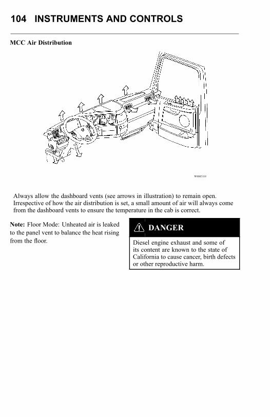
104 INSTRUMENTS AND CONTROLS
MCC Air Distribution
W8003110
Always allow the dashboard vents (see arrows in illustration) to remain open.Irrespective of how the air distribution is set, a small amount of air will always comefrom the dashboard vents to ensure the temperature in the cab is correct.
Note: Floor Mode: Unheated air is leakedto the panel vent to balance the heat risingfrom the floor.
DANGER
Diesel engine exhaust and some ofits content are known to the state ofCalifornia to cause cancer, birth defectsor other reproductive harm.
INSTRUMENTS AND CONTROLS 105
If at any time there is any question whether fumes are entering the cab, determine thecause of the fumes and have it corrected as soon as possible. If the vehicle must bedriven under these conditions, drive only with all windows open.Protect against carbon monoxide entry into the cab. Keep the engine exhaust system,cab and cab ventilation system properly maintained. It is recommended that theexhaust system and cab are inspected by a competent technician:
• At every engine oil change.• Whenever a change is noticed in the sound of the exhaust system.• Whenever the exhaust system, underbody or cab is damaged.To allow proper operation of the vehicle ventilation system, keep the inlet grille at thebase of the windshield clear of snow, ice, leaves and other obstructions at all times.DO NOT park the vehicle and let the engine run or idle for more than 10 minutes withthe ventilation system control switch in the OFF position. Even with the ventilationsystem ON, running the engine while parked or stopped for long periods of time isnot recommended. Entry of carbon monoxide into the cab is possible with a poorlyrepaired, damaged or corroded exhaust system or cab.DO NOT run the engine in confined areas, such as garages or next to a building, anymore than necessary. The area must be properly ventilated. When the vehicle must bestopped with the engine running for more than a few minutes:
• Adjust the heating or cooling system to force outside air into the cab. Do this bysetting the fan to medium or high speed and with the controls set in any positionexcept for recirculation of air inside of the cab.
• Keep the exhaust pipe area clear to help reduce the buildup of exhaust gas underthe vehicle.

106 INSTRUMENTS AND CONTROLS
SLEEPER CLIMATE UNITThe sleeper cabs have an A/C and heater unit that is located in the passenger sideluggage compartment. The sleeper unit operates from the same heater and airconditioning supply as the main unit. The heater can be operated independently fromthe main unit as long as the engine is running.For the air conditioning to operate, the engine must be running, the air conditioningbutton must be pressed in and the fan control must be set at least for speed 1 on themain control panel.Air is taken from the sleeper area through a filter in the lower bunk support wall andheated or cooled in the "underbunk" unit. Outlet air can be directed with the vents inthe side walls.For the best results when using the air conditioning, direct the air flow upward in thesleeper area.
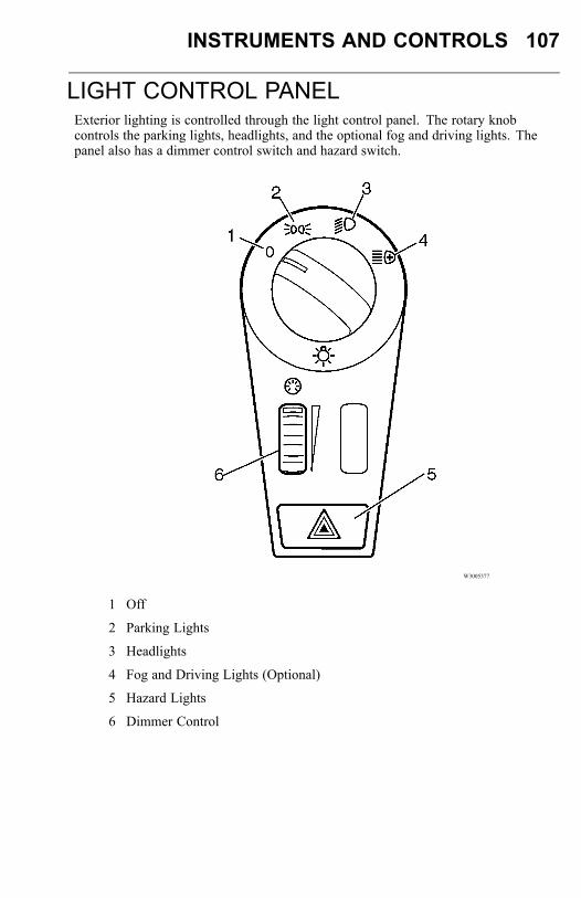
INSTRUMENTS AND CONTROLS 107
LIGHT CONTROL PANELExterior lighting is controlled through the light control panel. The rotary knobcontrols the parking lights, headlights, and the optional fog and driving lights. Thepanel also has a dimmer control switch and hazard switch.
W3005377
1 Off
2 Parking Lights
3 Headlights
4 Fog and Driving Lights (Optional)
5 Hazard Lights
6 Dimmer Control
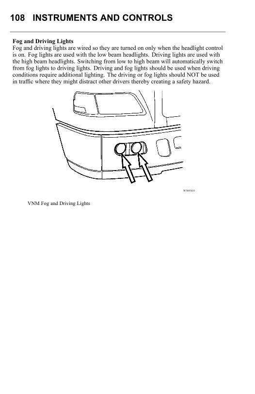
108 INSTRUMENTS AND CONTROLS
Fog and Driving LightsFog and driving lights are wired so they are turned on only when the headlight controlis on. Fog lights are used with the low beam headlights. Driving lights are used withthe high beam headlights. Switching from low to high beam will automatically switchfrom fog lights to driving lights. Driving and fog lights should be used when drivingconditions require additional lighting. The driving or fog lights should NOT be usedin traffic where they might distract other drivers thereby creating a safety hazard.
W3005410
VNM Fog and Driving Lights
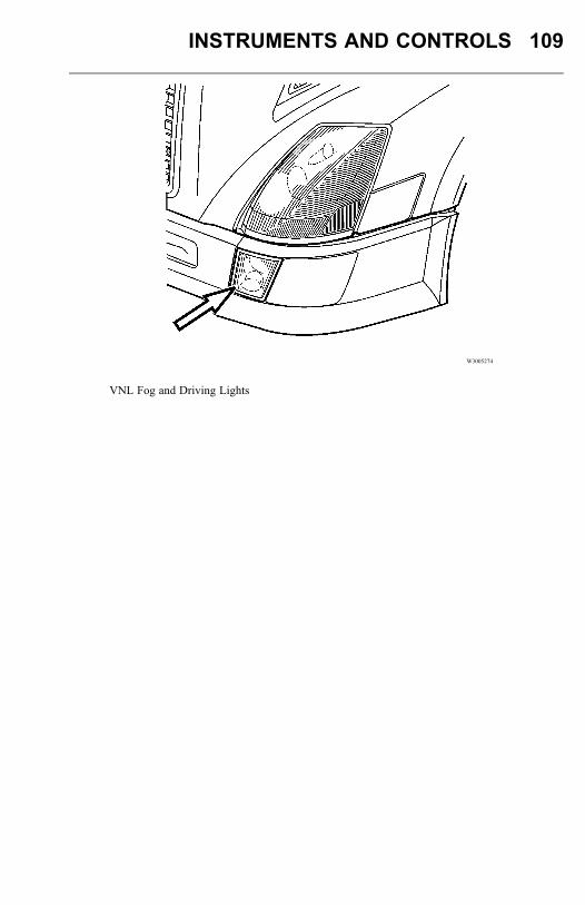
INSTRUMENTS AND CONTROLS 109
W3005274
VNL Fog and Driving Lights
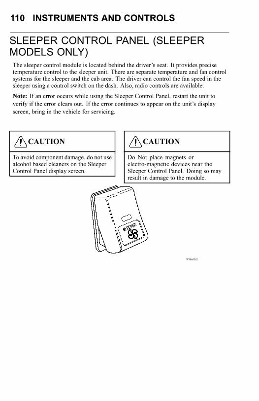
110 INSTRUMENTS AND CONTROLS
SLEEPER CONTROL PANEL (SLEEPERMODELS ONLY)The sleeper control module is located behind the driver’s seat. It provides precisetemperature control to the sleeper unit. There are separate temperature and fan controlsystems for the sleeper and the cab area. The driver can control the fan speed in thesleeper using a control switch on the dash. Also, radio controls are available.
Note: If an error occurs while using the Sleeper Control Panel, restart the unit toverify if the error clears out. If the error continues to appear on the unit’s displayscreen, bring in the vehicle for servicing.
CAUTION
To avoid component damage, do not usealcohol based cleaners on the SleeperControl Panel display screen.
CAUTION
Do Not place magnets orelectro-magnetic devices near theSleeper Control Panel. Doing so mayresult in damage to the module.
W3005382
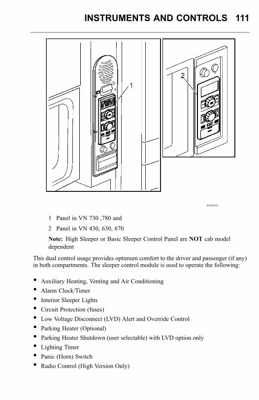
INSTRUMENTS AND CONTROLS 111
W3030107
1 Panel in VN 730 ,780 and
2 Panel in VN 430, 630, 670
Note: High Sleeper or Basic Sleeper Control Panel are NOT cab modeldependent
This dual control usage provides optimum comfort to the driver and passenger (if any)in both compartments. The sleeper control module is used to operate the following:
• Auxiliary Heating, Venting and Air Conditioning• Alarm Clock/Timer• Interior Sleeper Lights• Circuit Protection (fuses)• Low Voltage Disconnect (LVD) Alert and Override Control• Parking Heater (Optional)• Parking Heater Shutdown (user selectable) with LVD option only• Lighting Timer• Panic (Horn) Switch• Radio Control (High Version Only)
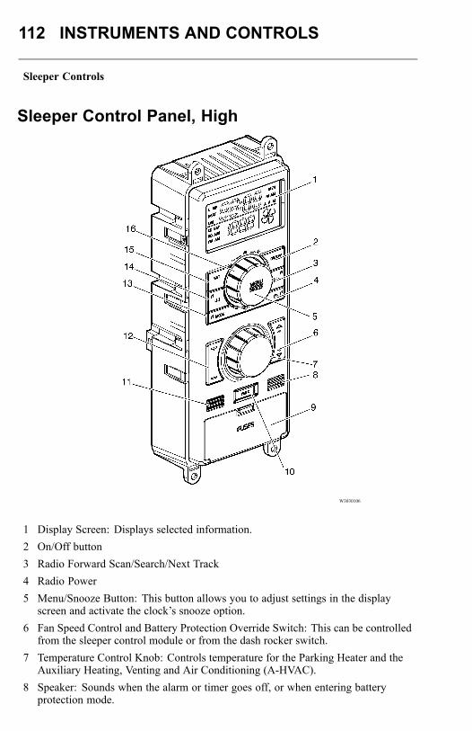
112 INSTRUMENTS AND CONTROLS
Sleeper Controls
Sleeper Control Panel, High
W3030106
1 Display Screen: Displays selected information.2 On/Off button3 Radio Forward Scan/Search/Next Track4 Radio Power5 Menu/Snooze Button: This button allows you to adjust settings in the display
screen and activate the clock’s snooze option.6 Fan Speed Control and Battery Protection Override Switch: This can be controlled
from the sleeper control module or from the dash rocker switch.7 Temperature Control Knob: Controls temperature for the Parking Heater and the
Auxiliary Heating, Venting and Air Conditioning (A-HVAC).8 Speaker: Sounds when the alarm or timer goes off, or when entering battery
protection mode.

INSTRUMENTS AND CONTROLS 113
9 Fuses10 Panic button11 LED: Only used for low voltage conditions.12 Overhead Lamp Switch: This can be controlled from the sleeper control module or
from the dash rocker switch.13 Mode Switch: Changes mode of radio14 Radio Reverse Scan/Search/Next Track15 Set button16 Increment/Decrement Knob: Use this knob to adjust the Volume level.

114 INSTRUMENTS AND CONTROLS
Sleeper Control Panel, Basic
W3030078
1 Overhead Lamp Switch: This can be controlled from the sleeper control module orfrom the dash rocker switch.
2 Speaker: Sounds when the alarm or timer goes off, or when entering batteryprotection mode.
3 Display Screen: Displays selected information.4 Menu/Snooze Button: This button allows you to adjust settings in the display
screen and activate the clock’s snooze option.5 On/Off6 Set button7 Temperature Control Knob: Controls temperature for the Parking Heater and the
Auxiliary Heating, Venting and Air Conditioning (A-HVAC).8 Fan Speed9 LED: Only used for low voltage conditions.10 Panic button11 Fuses12 Increment/Decrement Knob: Use this knob to adjust the Volume level.
INSTRUMENTS AND CONTROLS 115
Set ClockTo set the clock for the Sleeper Control Panel, perform the following:1 Press the SET button.2 To set the clock to either ’12’ or ’24’ hour increments, use the “+” or “-” knob.3 Press the SET button.4 To set the clock Hour, use the “+” or “-” knob.5 Press the SET button.6 To set the clock Minute, use the “+” or “-” knob.7 Press the SET button to confirm settings.
Once the clock is set to the desired time, the clock displays.
Note: After 7 seconds of inactivity the display returns to clock. Press the SET buttonto restart.
Note: On vehicles equipped with the High Sleeper Control Panel is connected to theInstrument Cluster and the Clock will automatically be updated by the time messagethe Instrument Cluster sends out.
Note: On vehicles equipped with the Basic Sleeper Control Panel it is NOT connectedto the Instrument Cluster so the clock will blink until the user sets the clock.
Note: The clockWill need to be set every time the battery disconnect switch is used.
Note: Only 12 hr format shows the AM/PM icon
Note: User settings will be stored in memory, Sleeper Control functions will not beactivated when the disconnect switch is turned back on. The user will need to turnthe functions back-on manually.
Note: The vehicle is equipped with a battery protection system. The vehicle detectswhen the batteries are excessively discharged. If this occurs, an indication light andaudible alarm are emitted. This indicates that some of the circuits will be disconnectedin order to maintain engine starting capacity. If a battery disconnect occurs thedefaults for the sleeper control panel are saved. These default settings are availableafter the battery disconnect is cancelled.
Note: The Panic button activates a 5 second horn audible. The Panic button mustbe held for 2.5 seconds for the horn to sound. This delay avoids an inadvertentactivation of the horn.
Note: After 5 minutes of inactivity the display will shut off.
116 INSTRUMENTS AND CONTROLS
DimmerTo adjust the backlighting brightness level, perform the following:1 Press the MENU button.2 Press the SET button.3 Use the “+” or “-” knob to adjust the brightness level.4 Press the SET button to confirm settings.
Once the backlighting brightness is set to the desired level, the display goes backto the clock.
Note: After 7 seconds of inactivity the display returns to clock. Press the MENUbutton to restart.
Turning Alarm On/OffTo turn the alarm On/Off, perform the following:1 Press the MENU button twice.2 Press ON/OFF.3 Press the SET button to confirm settings.
This process toggles the Alarm between the On/Off position and returns to the clockdisplay. The Alarm icon is toggled on or off accordingly.
Note: After 7 seconds of inactivity the display returns to clock. Press the MENUbutton to restart.
INSTRUMENTS AND CONTROLS 117
Setting Alarm TimeTo set the alarm time, perform the following:1 Press the MENU button twice.2 Press SET button.3 Use the “+” or “-” knob to adjust the hour value.4 Press SET to accept the set hour.5 Use the “+” or “-” knob to adjust the minute value.6 Press the SET button to confirm settings.
Once the alarm time is set the display returns to the clock and the Alarm icon isilluminated.
Note: After 7 seconds of inactivity the display returns to clock. Press the MENUbutton to restart.
Turning Heater On/OffTo turn the heater On/Off , perform the following:1 Press theMENU button three times.
The Heat icon blinks. The heat control value displays either as OFF, Auto orCycle depending on the previous setting.
2 Press ON/OFF button to toggle between the On/Off position.3 After selecting the desired setting, press the SET button to confirm settings.
The Parking Heater is turned On/Off. The Sleeper Control Panel display returns tothe clock. The Heat icon is tuned On/Off accordingly. The LVD icon is also turnedON/OFF depending on the LVD control of the Parking Heater setting, explainedbelow in this section.
Note: After 7 seconds of inactivity the display returns to clock. Press the MENUbutton to restart.
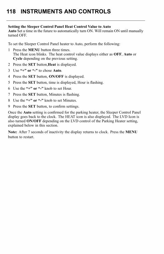
118 INSTRUMENTS AND CONTROLS
Setting the Sleeper Control Panel Heat Control Value to AutoAuto Set a time in the future to automatically turn ON. Will remain ON until manuallyturned OFF.
To set the Sleeper Control Panel heater to Auto, perform the following:1 Press theMENU button three times.
The Heat icon blinks. The heat control value displays either as OFF, Auto orCycle depending on the previous setting.
2 Press the SET button,Heat is displayed.3 Use “+” or “-” to chose Auto.4 Press the SET button, ON/OFF is displayed.5 Press the SET button, time is displayed, Hour is flashing.6 Use the “+” or “-” knob to set Hour.7 Press the SET button, Minutes is flashing.8 Use the “+” or “-” knob to set Minutes.9 Press the SET button, to confirm settings.Once the Auto setting is confirmed for the parking heater, the Sleeper Control Paneldisplay goes back to the clock. The HEAT icon is also displayed. The LVD Icon isalso turned ON/OFF depending on the LVD control of the Parking Heater setting,explained below in this section.
Note: After 7 seconds of inactivity the display returns to clock. Press theMENUbutton to restart.

INSTRUMENTS AND CONTROLS 119
Setting the Sleeper Control Panel Heat Control Value to CycleCycle Set a cycle time to continuously cycle between ON/OFF
To set the Sleeper Control Panel heater to Cycle, perform the following:1 Press theMENU button three times.
The Heat icon blinks. The heat control value displays either as OFF, Auto orCycle depending on the previous setting.
2 Press the SET button,Heat is displayed.3 Use “+” or “-” to chose Cycle.4 Press the SET button, ON/OFF is displayed.5 Press the SET button, time is displayed, Hour is flashing.6 Use the “+” or “-” knob to set Hour.7 Press the SET button, Minutes is flashing.8 Use the “+” or “-” knob to set Minutes.9 Press the SET button, to confirm settings.
Once the Cycle setting is confirmed for the parking heater, the Sleeper Control Paneldisplay goes back to the clock. The HEAT icon is also displayed. The LVD Icon isalso turned ON/OFF depending on the LVD control of the Parking Heater setting,explained below in this section.
Note: After 7 seconds of inactivity the display returns to clock. Press theMENUbutton to restart.
Turning Sleeper Control Panel Timer On/OffTo turn the Sleeper Control Panel Timer on or off, perform the following:1 Press theMENU button four times.
The Timer icon blinks on or off.2 Press the ON/OFF button until ON or OFF is displayed.3 Press the SET button to confirm settings.
Once the Timer setting is confirmed, the Sleeper Control Panel display goes back tothe clock. The TIMER icon is also displayed.
Note: After 7 seconds of inactivity the display returns to clock. Press theMENUbutton to restart.

120 INSTRUMENTS AND CONTROLS
Setting Sleeper Control Panel TimerTo set the Sleeper Control Panel Timer, perform the following:1 Press theMENU button four times.
The TIMER icon blinks.2 Press the SET button.3 To set the Timer minutes, use the “+” or “-” knob.4 Press the SET button.5 To set the Timer seconds, use the “+” or “-” knob.6 Press the SET button to confirm settings.
Once the Timer is set to the desired time, the display goes back to the clock and theTIMER icon is shown.
Note: Alarm will sound when the Timer counter reaches 00:00. Press the ON/OFFbutton, to turn alarm OFF .
Note: After 7 seconds of inactivity the display returns to clock. Press theMENUbutton to restart.
Turning the LVD Audible ON/OFFTo turn the LVD On/Off for the Sleeper Control Panel, perform the following:1 Press theMENU button five times.2 Press the ON/OFF button.3 Press the SET button to confirm settings.
The LVD audible alarm toggles between On/Off and the display goes back to theclock.
Setting the LVD Control of the Parking HeaterTo set whether the LVD will turn off the parking heater, perform the following:1 Press theMENU button five times.
The LVD icon blinks and the display shows ON.2 To set the Parking Heater shutdown to ON/OFF, press the SET button (Heat and
LVD icon will blink).3 Use the “+” or “-” knob to chose ON/OFF.4 Press the SET button to confirm settings.
The LVD is set to shut down the parking heater. The display returns to the clock andthe LVD icon is illuminated The setting is active only if the LVD is set in the Onposition and the Heater is active.
Note: After 7 seconds of inactivity the display returns to clock. Press theMENUbutton to restart.
INSTRUMENTS AND CONTROLS 121
Turning the Lamp Timer ON/OFFLamp Timer Turns interior lamps off after a set time.To turn the Lamp Timer On/Off for the Sleeper Control Panel, perform the following:1 Press theMENU button six times.
The Lamp Icon flashes.2 Press ON/OFF.3 Press the SET button to confirm settings.
The Lamp Timer is turned On/Off, and the display returns to the clock. The Lampicon toggles between On/Off accordingly.
Note: After 7 seconds of inactivity the display returns to clock. Press theMENUbutton to restart.
Setting the Lamp TimerTo set the Lamp Timer, perform the following:1 Press theMENU button six times.
The Lamp Icon flashes.2 Press the SET button.3 To set the timer minutes, use the “+” or “-” knob.4 Press the SET button.5 To set the timer seconds, use the “+” or “-” knob.6 Press the SET button to confirm settings..
The Lamp timer is set to the desired time. The display returns to the clock and theLamp Icon is illuminated.
Note: After 7 seconds of inactivity the display returns to clock. Press theMENUbutton to restart.
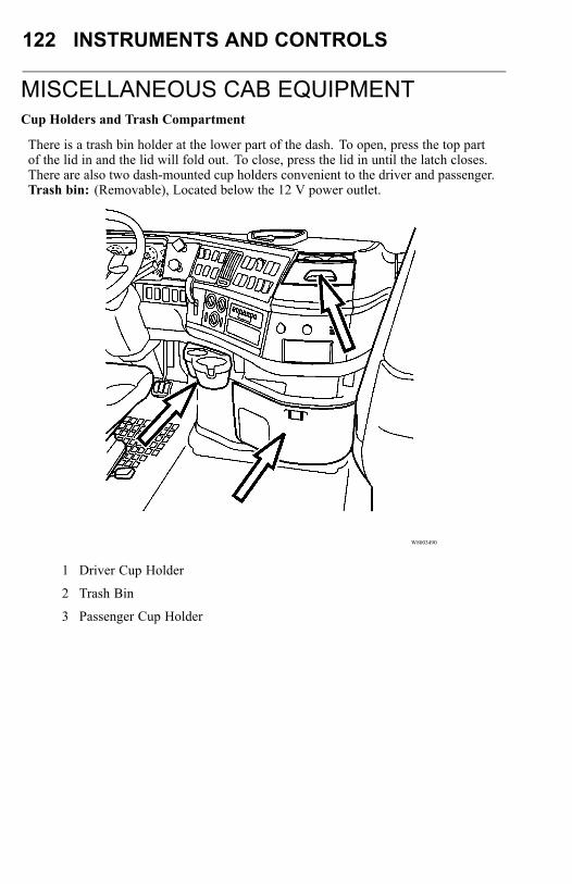
122 INSTRUMENTS AND CONTROLS
MISCELLANEOUS CAB EQUIPMENTCup Holders and Trash Compartment
There is a trash bin holder at the lower part of the dash. To open, press the top partof the lid in and the lid will fold out. To close, press the lid in until the latch closes.There are also two dash-mounted cup holders convenient to the driver and passenger.Trash bin: (Removable), Located below the 12 V power outlet.
W8003490
1 Driver Cup Holder
2 Trash Bin
3 Passenger Cup Holder
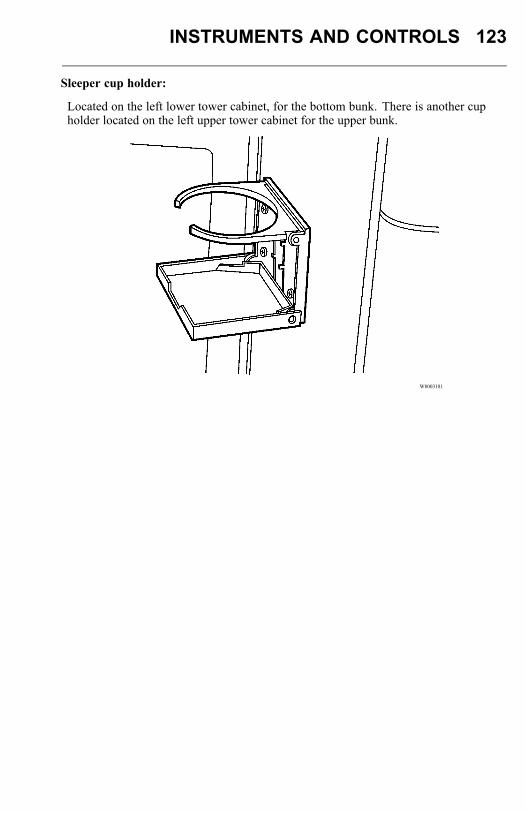
INSTRUMENTS AND CONTROLS 123
Sleeper cup holder:
Located on the left lower tower cabinet, for the bottom bunk. There is another cupholder located on the left upper tower cabinet for the upper bunk.
W8003181
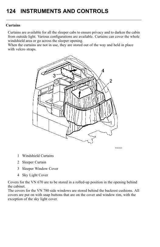
124 INSTRUMENTS AND CONTROLS
Curtains
Curtains are available for all the sleeper cabs to ensure privacy and to darken the cabinfrom outside light. Various configurations are available. Curtains can cover the wholewindshield area or go across the sleeper opening.When the curtains are not in use, they are stored out of the way and held in placewith velcro straps.
W8028428
1 Windshield Curtains
2 Sleeper Curtain
3 Sleeper Window Cover
4 Sky Light Cover
Covers for the VN 670 are to be stored in a rolled-up position in the opening behindthe cabinet.The covers for the VN 780 side windows are stored behind the backrest cushions. Allcovers are put on with snap buttons that are on the cover and window rim, with theexception of the sky light cover.
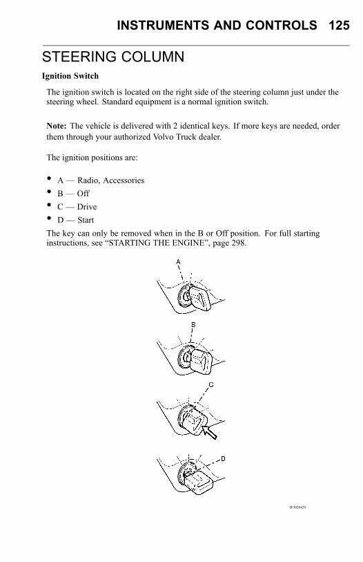
INSTRUMENTS AND CONTROLS 125
STEERING COLUMNIgnition Switch
The ignition switch is located on the right side of the steering column just under thesteering wheel. Standard equipment is a normal ignition switch.
Note: The vehicle is delivered with 2 identical keys. If more keys are needed, orderthem through your authorized Volvo Truck dealer.
The ignition positions are:
• A — Radio, Accessories• B — Off• C — Drive• D — StartThe key can only be removed when in the B or Off position. For full startinginstructions, see “STARTING THE ENGINE”, page 298.
W3028429
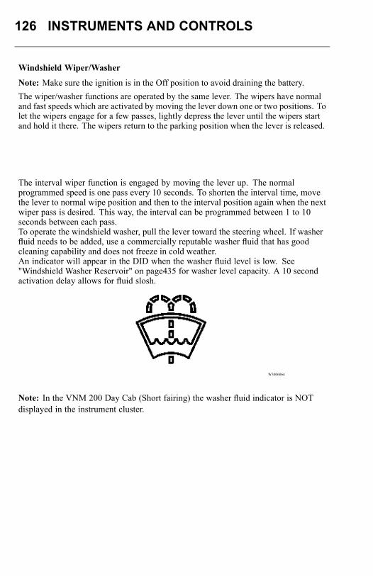
126 INSTRUMENTS AND CONTROLS
Windshield Wiper/Washer
Note: Make sure the ignition is in the Off position to avoid draining the battery.The wiper/washer functions are operated by the same lever. The wipers have normaland fast speeds which are activated by moving the lever down one or two positions. Tolet the wipers engage for a few passes, lightly depress the lever until the wipers startand hold it there. The wipers return to the parking position when the lever is released.
The interval wiper function is engaged by moving the lever up. The normalprogrammed speed is one pass every 10 seconds. To shorten the interval time, movethe lever to normal wipe position and then to the interval position again when the nextwiper pass is desired. This way, the interval can be programmed between 1 to 10seconds between each pass.To operate the windshield washer, pull the lever toward the steering wheel. If washerfluid needs to be added, use a commercially reputable washer fluid that has goodcleaning capability and does not freeze in cold weather.An indicator will appear in the DID when the washer fluid level is low. See"Windshield Washer Reservoir" on page435 for washer level capacity. A 10 secondactivation delay allows for fluid slosh.
W3006064
Note: In the VNM 200 Day Cab (Short fairing) the washer fluid indicator is NOTdisplayed in the instrument cluster.
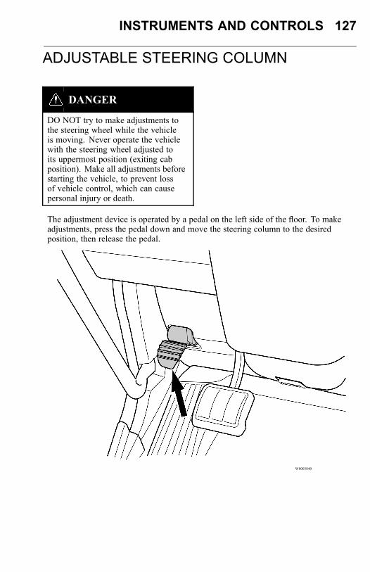
INSTRUMENTS AND CONTROLS 127
ADJUSTABLE STEERING COLUMN
DANGER
DO NOT try to make adjustments tothe steering wheel while the vehicleis moving. Never operate the vehiclewith the steering wheel adjusted toits uppermost position (exiting cabposition). Make all adjustments beforestarting the vehicle, to prevent lossof vehicle control, which can causepersonal injury or death.
The adjustment device is operated by a pedal on the left side of the floor. To makeadjustments, press the pedal down and move the steering column to the desiredposition, then release the pedal.
W8003840
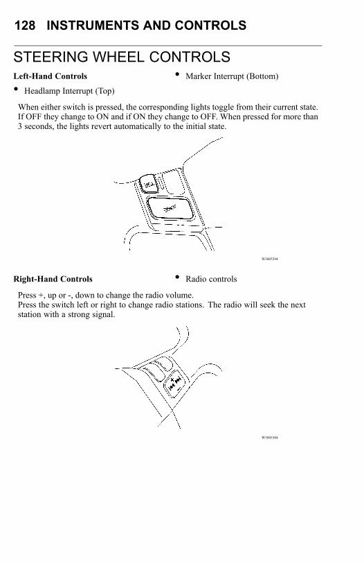
128 INSTRUMENTS AND CONTROLS
STEERING WHEEL CONTROLSLeft-Hand Controls
• Headlamp Interrupt (Top)
• Marker Interrupt (Bottom)
When either switch is pressed, the corresponding lights toggle from their current state.If OFF they change to ON and if ON they change to OFF. When pressed for more than3 seconds, the lights revert automatically to the initial state.
W3005294
Right-Hand Controls • Radio controls
Press +, up or -, down to change the radio volume.Press the switch left or right to change radio stations. The radio will seek the nextstation with a strong signal.
W3005304
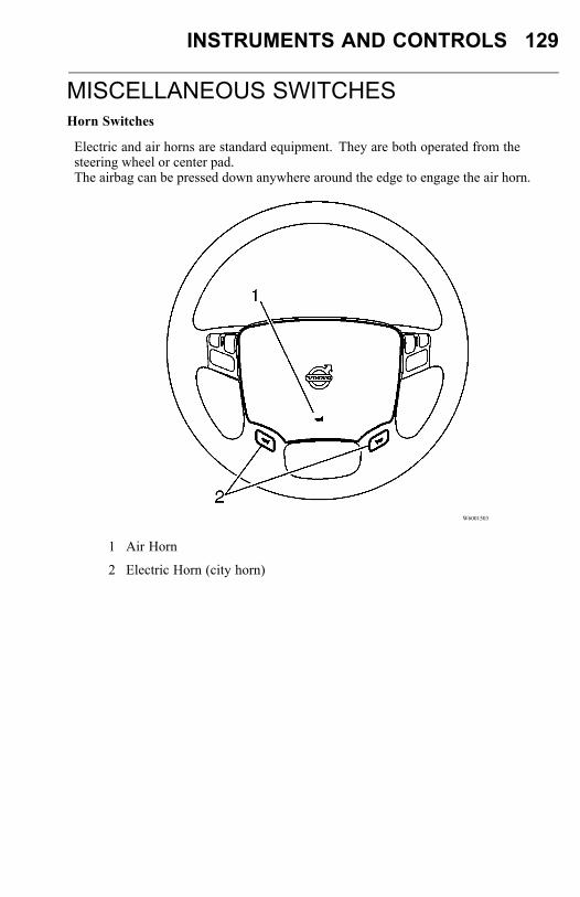
INSTRUMENTS AND CONTROLS 129
MISCELLANEOUS SWITCHESHorn Switches
Electric and air horns are standard equipment. They are both operated from thesteering wheel or center pad.The airbag can be pressed down anywhere around the edge to engage the air horn.
W6001503
1 Air Horn
2 Electric Horn (city horn)
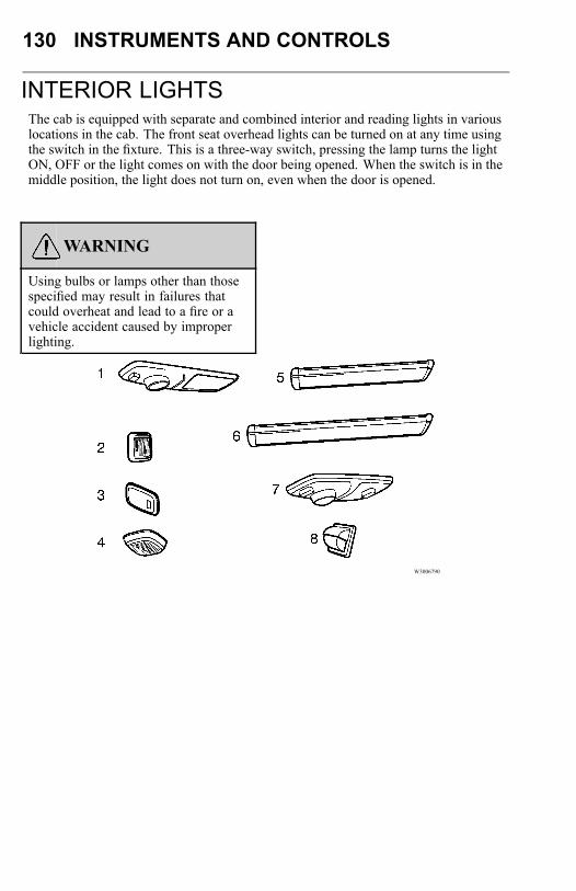
130 INSTRUMENTS AND CONTROLS
INTERIOR LIGHTSThe cab is equipped with separate and combined interior and reading lights in variouslocations in the cab. The front seat overhead lights can be turned on at any time usingthe switch in the fixture. This is a three-way switch, pressing the lamp turns the lightON, OFF or the light comes on with the door being opened. When the switch is in themiddle position, the light does not turn on, even when the door is opened.
WARNING
Using bulbs or lamps other than thosespecified may result in failures thatcould overheat and lead to a fire or avehicle accident caused by improperlighting.
W3006790

INSTRUMENTS AND CONTROLS 131
Interior Lights
Chart Number Description
1 Overhead Dome Lamp
1 Overhead Dome/Spot Lamp connected to door
2 Door Courtesy Lamp
3 Dome Lamp — Sleeper
4 Reading Lamp under bunk storage
5 Reading Lamp
6 Overhead Lamp — Short
7 Overhead Lamp — Long
8 Overhead Dome/Spot Lamp
Note: To prevent short service lift, DO NOT touch the glass surface of thereplacement bulb.
WARNING
The lamp assemblies may get warm tothe touch. DO NOT cover the lampswith any object.
Most of the vehicle interior lights are activated by pressing on a push button on thelower end of the lamp. There are two external switches for the interior lights, onelocated on the dash panel, to the immediate left of the steering column, and the otheris on the sleeper area control panel.
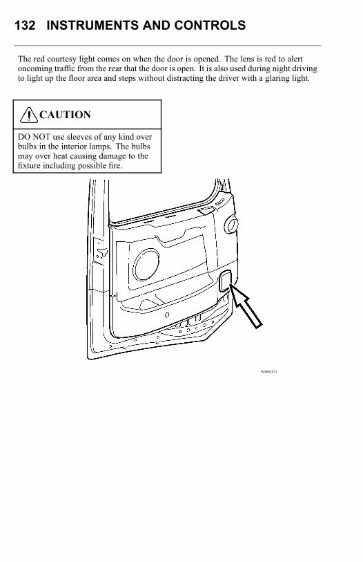
132 INSTRUMENTS AND CONTROLS
The red courtesy light comes on when the door is opened. The lens is red to alertoncoming traffic from the rear that the door is open. It is also used during night drivingto light up the floor area and steps without distracting the driver with a glaring light.
CAUTION
DO NOT use sleeves of any kind overbulbs in the interior lamps. The bulbsmay over heat causing damage to thefixture including possible fire.
W8003521

INSTRUMENTS AND CONTROLS 133
The door latch has an internal switch that operates all door-activated lights.
W8003522
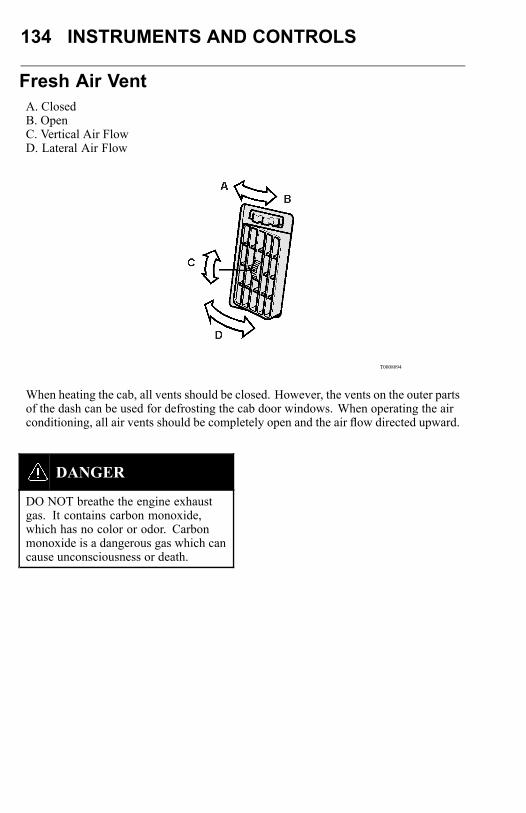
134 INSTRUMENTS AND CONTROLS
Fresh Air VentA. ClosedB. OpenC. Vertical Air FlowD. Lateral Air Flow
T0008094
When heating the cab, all vents should be closed. However, the vents on the outer partsof the dash can be used for defrosting the cab door windows. When operating the airconditioning, all air vents should be completely open and the air flow directed upward.
DANGER
DO NOT breathe the engine exhaustgas. It contains carbon monoxide,which has no color or odor. Carbonmonoxide is a dangerous gas which cancause unconsciousness or death.

INSTRUMENTS AND CONTROLS 135
CAB VENTILATION, SLEEPERIn sleeper versions (except the VN 780 and VN 730) there is a fresh air vent locatedon each cab side wall. It opens to two positions so the air flow can be regulated.
W8003135
The vent also opens toward the front or toward the rear. This can be used for forcingair into the cab (open toward the front) or for venting air out of the cab (open towardthe rear).
CAUTION
The vent should not be used duringrain, while washing the vehicle or othercircumstances where water may enterthe cab while the vent is open. Toprevent leaks, make sure the handlerollers are on the top center part of thecams.
Earlier production versions of the VN 780 are equipped with four hinged sidewindows in the sleeper area. Later production versions have two hinged side windowsin the sleeper area and two upper vent windows.Earlier production versions of the VN 670 have only the two upper windows. Laterproduction versions have two upper vent windows.
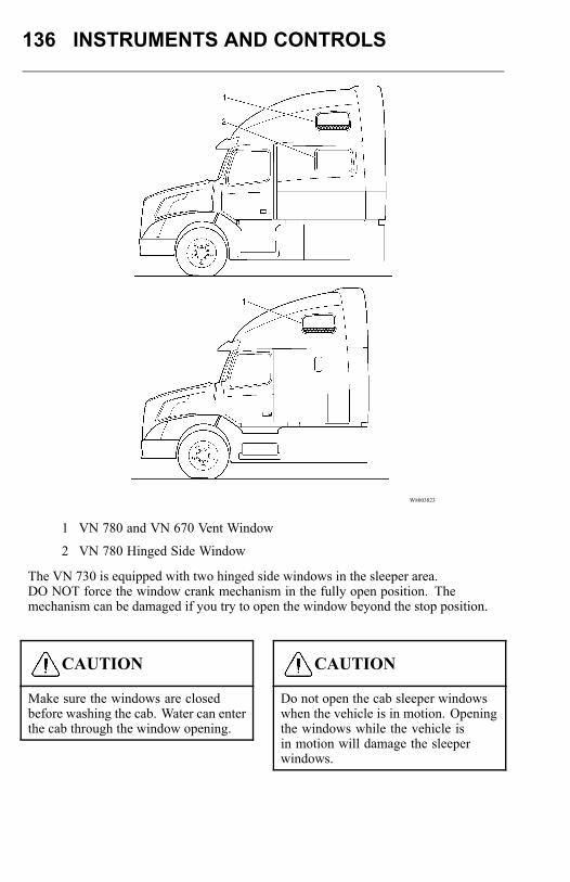
136 INSTRUMENTS AND CONTROLS
W8003823
1 VN 780 and VN 670 Vent Window
2 VN 780 Hinged Side Window
The VN 730 is equipped with two hinged side windows in the sleeper area.DO NOT force the window crank mechanism in the fully open position. Themechanism can be damaged if you try to open the window beyond the stop position.
CAUTION
Make sure the windows are closedbefore washing the cab. Water can enterthe cab through the window opening.
CAUTION
Do not open the cab sleeper windowswhen the vehicle is in motion. Openingthe windows while the vehicle isin motion will damage the sleeperwindows.
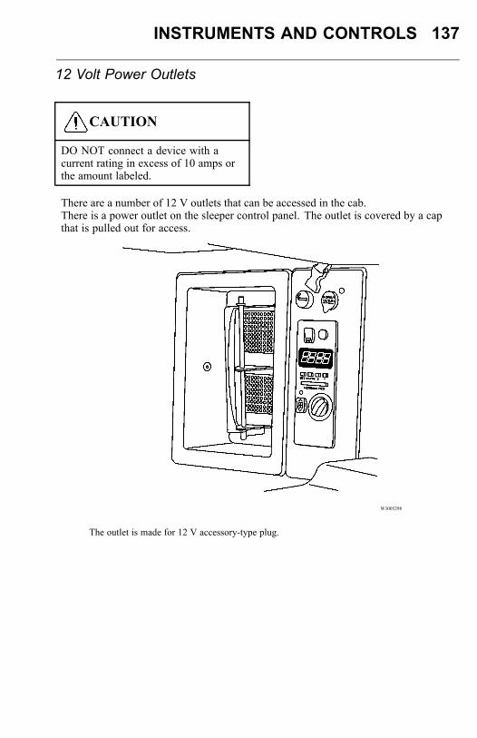
INSTRUMENTS AND CONTROLS 137
12 Volt Power Outlets
CAUTION
DO NOT connect a device with acurrent rating in excess of 10 amps orthe amount labeled.
There are a number of 12 V outlets that can be accessed in the cab.There is a power outlet on the sleeper control panel. The outlet is covered by a capthat is pulled out for access.
W3005298
The outlet is made for 12 V accessory-type plug.
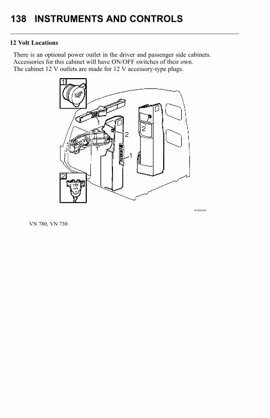
138 INSTRUMENTS AND CONTROLS
12 Volt Locations
There is an optional power outlet in the driver and passenger side cabinets.Accessories for this cabinet will have ON/OFF switches of their own.The cabinet 12 V outlets are made for 12 V accessory-type plugs.
W3005508
VN 780, VN 730

INSTRUMENTS AND CONTROLS 139
W3005500
VN 780, VN 730

140 INSTRUMENTS AND CONTROLS
Inverter Switch 12 V DC to 120 V AC
DANGER
When parked on wet ground, avoidusing an external power source toconnect the cab power plug. Wateris a conductor of electricity. In wetconditions, electrical shock can occurwhich can result in personal injury ordeath.
This switch turns ON the optional power inverter, located near the batterycompartment.The power inverter takes the DC voltage from the batteries and changes it to ACvoltage, which is then fed to the 120 V shore power electrical system within the cabarea.The power inverter option can be ordered only if the 120 V shore power electricalsystem is specified.
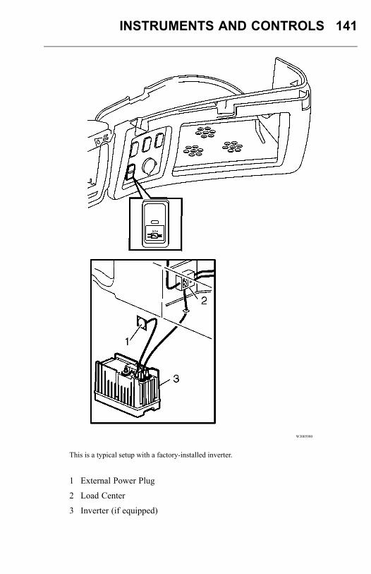
INSTRUMENTS AND CONTROLS 141
W3005980
This is a typical setup with a factory-installed inverter.
1 External Power Plug
2 Load Center
3 Inverter (if equipped)
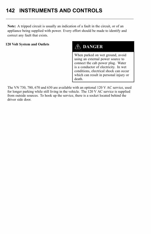
142 INSTRUMENTS AND CONTROLS
Note: A tripped circuit is usually an indication of a fault in the circuit, or of anappliance being supplied with power. Every effort should be made to identify andcorrect any fault that exists.
120 Volt System and Outlets DANGER
When parked on wet ground, avoidusing an external power source toconnect the cab power plug. Wateris a conductor of electricity. In wetconditions, electrical shock can occurwhich can result in personal injury ordeath.
The VN 730, 780, 670 and 630 are available with an optional 120 V AC service, usedfor longer parking while still living in the vehicle. The 120 V AC service is suppliedfrom outside sources. To hook up the service, there is a socket located behind thedriver side door.
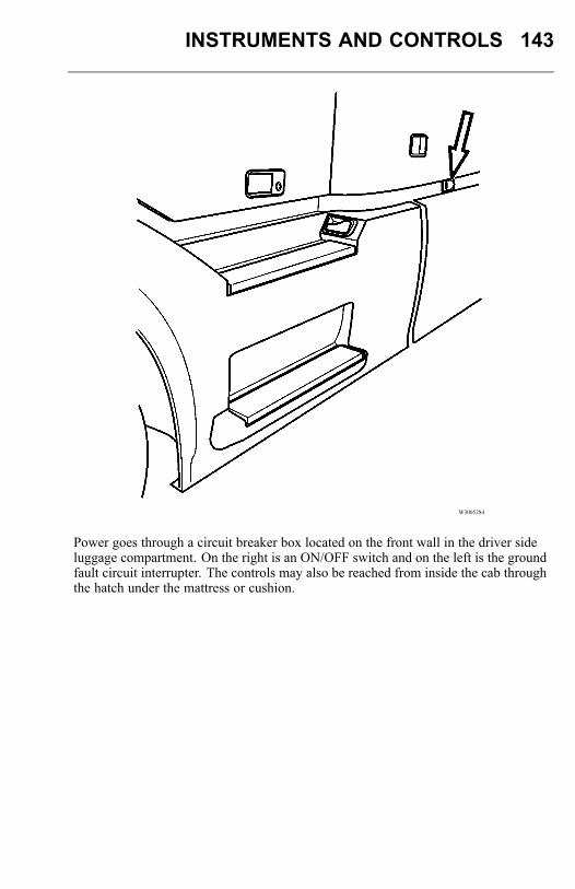
INSTRUMENTS AND CONTROLS 143
W3005284
Power goes through a circuit breaker box located on the front wall in the driver sideluggage compartment. On the right is an ON/OFF switch and on the left is the groundfault circuit interrupter. The controls may also be reached from inside the cab throughthe hatch under the mattress or cushion.
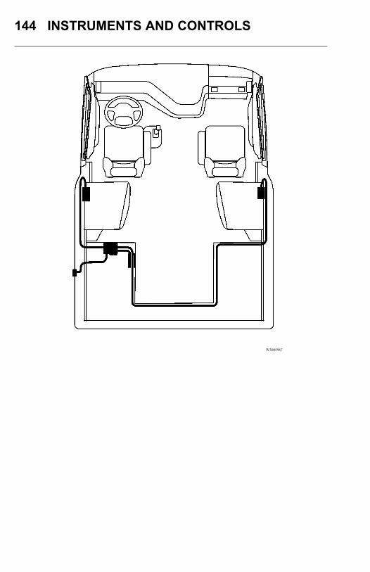
144 INSTRUMENTS AND CONTROLS
W3005967
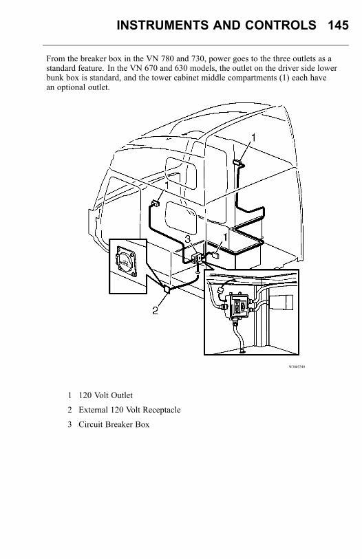
INSTRUMENTS AND CONTROLS 145
From the breaker box in the VN 780 and 730, power goes to the three outlets as astandard feature. In the VN 670 and 630 models, the outlet on the driver side lowerbunk box is standard, and the tower cabinet middle compartments (1) each havean optional outlet.
W3005340
1 120 Volt Outlet
2 External 120 Volt Receptacle
3 Circuit Breaker Box
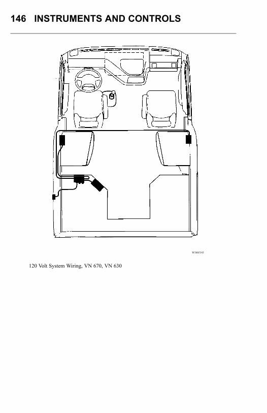
146 INSTRUMENTS AND CONTROLS
W3005343
120 Volt System Wiring, VN 670, VN 630
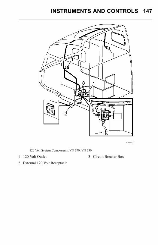
INSTRUMENTS AND CONTROLS 147
W3005342
120 Volt System Components, VN 670, VN 630
1 120 Volt Outlet
2 External 120 Volt Receptacle
3 Circuit Breaker Box
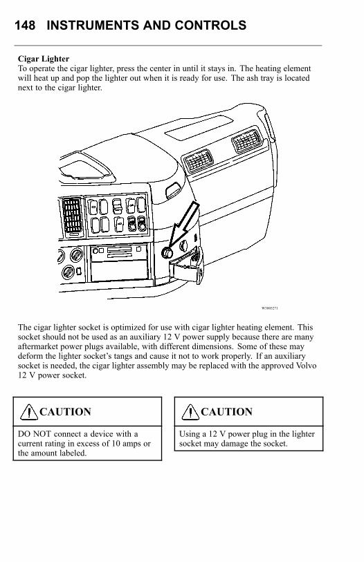
148 INSTRUMENTS AND CONTROLS
Cigar LighterTo operate the cigar lighter, press the center in until it stays in. The heating elementwill heat up and pop the lighter out when it is ready for use. The ash tray is locatednext to the cigar lighter.
W3005271
The cigar lighter socket is optimized for use with cigar lighter heating element. Thissocket should not be used as an auxiliary 12 V power supply because there are manyaftermarket power plugs available, with different dimensions. Some of these maydeform the lighter socket’s tangs and cause it not to work properly. If an auxiliarysocket is needed, the cigar lighter assembly may be replaced with the approved Volvo12 V power socket.
CAUTION
DO NOT connect a device with acurrent rating in excess of 10 amps orthe amount labeled.
CAUTION
Using a 12 V power plug in the lightersocket may damage the socket.
INSTRUMENTS AND CONTROLS 149
PARKING HEATER (OPTIONAL, SLEEPERMODELS ONLY)
DANGER
DO NOT fuel the vehicle or handleflammable liquids in the vicinity ofan operating parking heater. The fuelvapors can be ignited, causing anexplosion or fire resulting in severepersonal injury or death.
DANGER
DO NOT store flammable items closeto the parking heater or put items on topof it. Flammable items should not becloser than 50 mm (2 inches). The itemmay ignite and cause a fire resulting insevere personal injury or death.
DANGER
DO NOT run heater while vehicle is inan enclosed area. The exhaust gassescontain carbon monoxide (CO). If notvented to the atmosphere, there couldbe a buildup of dangerous levels of COwhich may lead to unconsciousness andlater death.
WARNING
The parking heater is a very hot object.DO NOT touch the heater when itis in operation or shortly thereafter.Touching a heater may cause burns toexposed skin.
CAUTION
The heater air inlet is located in thebunk wall in front of the heater. DONOT attempt to put small items or storeflat items between the bunk and thecabinet/refrigerator. The air intake canbe blocked which causes the heater tooverheat and shut down.
The parking heater is a diesel fuel burner that heats the air in the cab. Air is taken fromthe cab and returned heated. Combustion air and exhaust is taken from, and releasedto the outside air.To safeguard from the heater operating after a turnover accident, there is a fuelshut-off valve in the fuel delivery system.
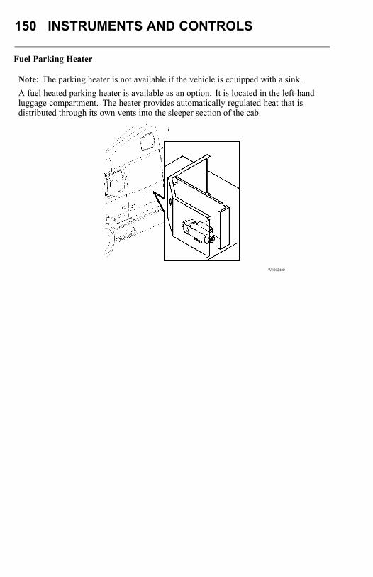
150 INSTRUMENTS AND CONTROLS
Fuel Parking Heater
Note: The parking heater is not available if the vehicle is equipped with a sink.A fuel heated parking heater is available as an option. It is located in the left-handluggage compartment. The heater provides automatically regulated heat that isdistributed through its own vents into the sleeper section of the cab.
W8002480
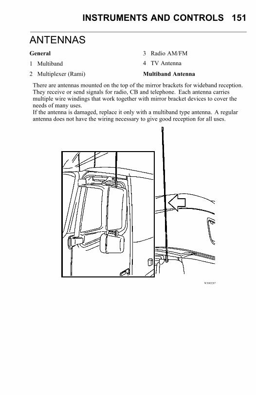
INSTRUMENTS AND CONTROLS 151
ANTENNASGeneral
1 Multiband
2 Multiplexer (Rami)
3 Radio AM/FM
4 TV Antenna
Multiband Antenna
There are antennas mounted on the top of the mirror brackets for wideband reception.They receive or send signals for radio, CB and telephone. Each antenna carriesmultiple wire windings that work together with mirror bracket devices to cover theneeds of many uses.If the antenna is damaged, replace it only with a multiband type antenna. A regularantenna does not have the wiring necessary to give good reception for all uses.
W3005287
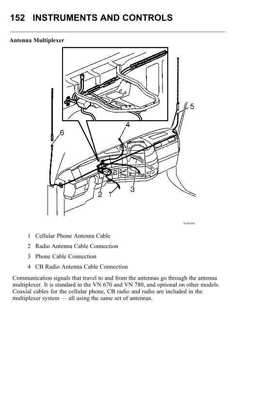
152 INSTRUMENTS AND CONTROLS
Antenna Multiplexer
W3005509
1 Cellular Phone Antenna Cable
2 Radio Antenna Cable Connection
3 Phone Cable Connection
4 CB Radio Antenna Cable Connection
Communication signals that travel to and from the antennas go through the antennamultiplexer. It is standard in the VN 670 and VN 780, and optional on other models.Coaxial cables for the cellular phone, CB radio and radio are included in themultiplexer system — all using the same set of antennas.
INSTRUMENTS AND CONTROLS 153
The multiplexer is accessed through the lower dash panels. Cable routing is asshown in the illustration above. Use only genuine Volvo replacement parts for thismultiplexer system; standard antennas will give unsatisfactory performance. Thewindings in the antennas are specific to this system: different sections of the antennaare used for the cellular phone, radio and CB.
Note: The location of the CB may vary. CB connections can be locatedeither in the dash or overhead storage area, depending on vehicle options. See"COMMUNICATION EQUIPMENT" “COMMUNICATION EQUIPMENT”, page155.
TELEVISION
WARNING
All items within the cab must be securedbefore the vehicle is set in motion. Thisincludes, but is not limited to, drinks,clothes, books, televisions, etc. In theevent of a sudden stop or collision,loose items could fly around inside thecab. This could cause personal injury.
The VN 780, VN 730, VN 670 and VN 630 are already equipped for TV with apre-installed antenna. The TV should be installed in the passenger side cabinet wherethere is a standard 12 V connection or an optional 120 V connection.To prevent the TV set from moving when the vehicle is driven, the strap in the TVstorage area should be tight around the set. Position the strap across the front cornersof the TV.
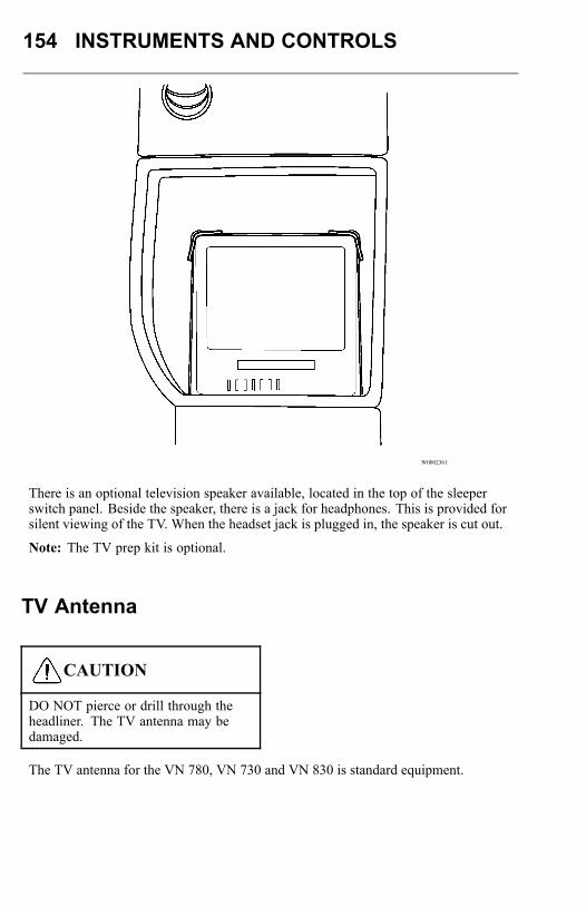
154 INSTRUMENTS AND CONTROLS
W0002361
There is an optional television speaker available, located in the top of the sleeperswitch panel. Beside the speaker, there is a jack for headphones. This is provided forsilent viewing of the TV. When the headset jack is plugged in, the speaker is cut out.
Note: The TV prep kit is optional.
TV Antenna
CAUTION
DO NOT pierce or drill through theheadliner. The TV antenna may bedamaged.
The TV antenna for the VN 780, VN 730 and VN 830 is standard equipment.
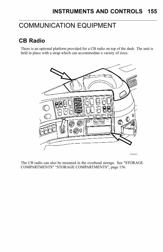
INSTRUMENTS AND CONTROLS 155
COMMUNICATION EQUIPMENT
CB RadioThere is an optional platform provided for a CB radio on top of the dash. The unit isheld in place with a strap which can accommodate a variety of sizes.
W3006382
The CB radio can also be mounted in the overhead storage. See "STORAGECOMPARTMENTS" “STORAGE COMPARTMENTS”, page 156.
156 INSTRUMENTS AND CONTROLS
Telephone
There is room on the dash for a mobile telephone. This can be hooked up to themultiplex box.If the vehicle is delivered with a multiplex box, the connecting end of the telephonecoaxial cable should be located at the lower dash cover.
Note: The panel must be removed to access the cable.
Road Relay (Optional)
The Road Relay is an engine communication tool that allows the driver to have fuelconsumption, time and mileage readouts and also programmed reminders for serviceintervals. The Road Relay should be permanently mounted directly below the radio.Collected data can be downloaded for use in a stationary computer where the data canbe collected and compared over time.
STORAGE COMPARTMENTS
DANGER
Heavy objects must be stored only inthe outside storage areas or securedon the floor. Cabinets and storagecompartments are designed for clothingand lighter personal effects only. In theevent of a collision, heavy, unsecuredobjects in overhead storage can comeloose and cause severe personal injuryor death to the driver or passengers.
WARNING
All items within the cab must be securedbefore the vehicle is set in motion. Thisincludes, but is not limited to, drinks,clothes, books, televisions, etc. In theevent of a collision, loose items couldfly around inside the cab. This couldcause personal injury.
CAUTION
DO NOT overload the cab suspension.Make sure the weight distribution isequal in the cab. Overloading thesuspension leads to poor ride andlowered driving comfort.

INSTRUMENTS AND CONTROLS 157
To prevent the television and microwave oven from moving when the vehicle isdriven, the strap in the storage area should be tight around the unit. Position the strapacross the front corners of the unit. Periodically, check that the strap is tight andretighten as necessary.
W0002361
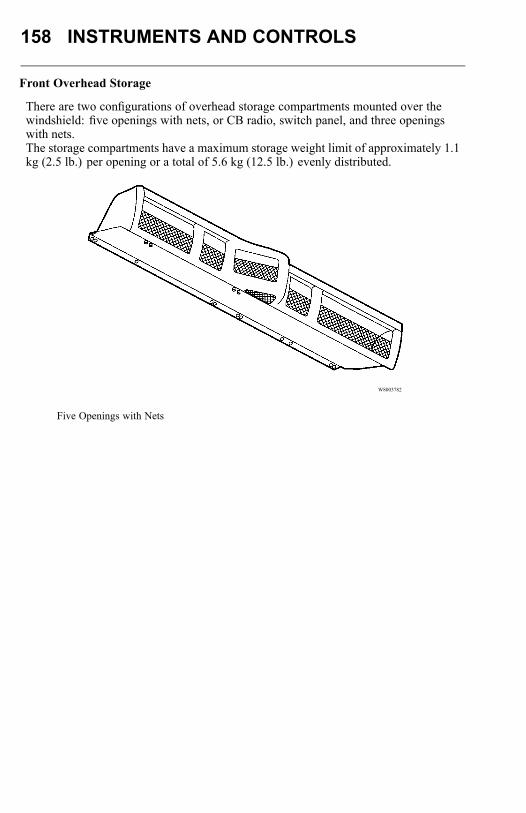
158 INSTRUMENTS AND CONTROLS
Front Overhead Storage
There are two configurations of overhead storage compartments mounted over thewindshield: five openings with nets, or CB radio, switch panel, and three openingswith nets.The storage compartments have a maximum storage weight limit of approximately 1.1kg (2.5 lb.) per opening or a total of 5.6 kg (12.5 lb.) evenly distributed.
W8003782
Five Openings with Nets
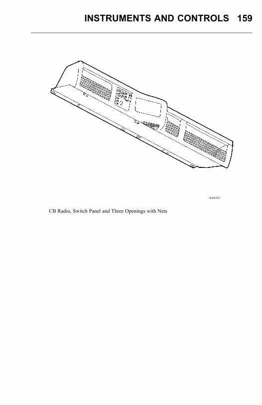
INSTRUMENTS AND CONTROLS 159
W8003821
CB Radio, Switch Panel and Three Openings with Nets

160 INSTRUMENTS AND CONTROLS
There are two configurations of forward overhead shelves at the front of the sleeper:without cabinets or with cabinets. The storage compartments have a maximum storageweight limit of approximately 3.6 kg (8 lb.) per section.
W8003794
Forward Overhead Shelf without Cabinets
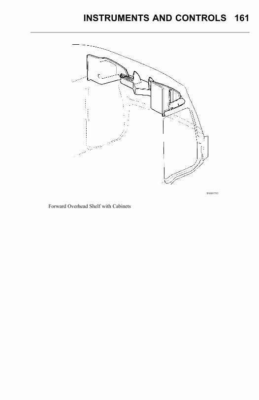
INSTRUMENTS AND CONTROLS 161
W8003793
Forward Overhead Shelf with Cabinets
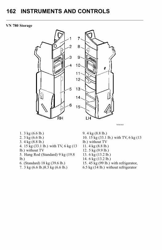
162 INSTRUMENTS AND CONTROLS
VN 780 Storage
W8003805
1. 3 kg (6.6 lb.)2. 3 kg (6.6 lb.)3. 4 kg (8.8 lb.)4. 15 kg (33.1 lb.) with TV, 6 kg (13lb.) without TV5. Hang Rod (Standard) 9 kg (19.8lb.)6. (Standard) 18 kg (39.6 lb.)7. 3 kg (6.6 lb.)8.3 kg (6.6 lb.)
9. 4 kg (8.8 lb.)10. 15 kg (33.1 lb.) with TV, 6 kg (13lb.) without TV11. 4 kg (8.8 lb.)12. 5 kg (9.9 lb.)13. 6 kg (13.2 lb.)14. 6 kg (13.2 lb.)15. 45 kg (99 lb.) with refrigerator,6.5 kg (14 lb.) without refrigerator
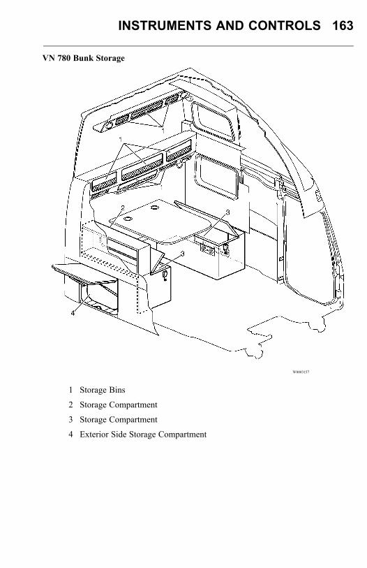
INSTRUMENTS AND CONTROLS 163
VN 780 Bunk Storage
W8003157
1 Storage Bins
2 Storage Compartment
3 Storage Compartment
4 Exterior Side Storage Compartment
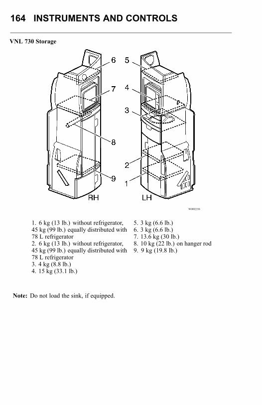
164 INSTRUMENTS AND CONTROLS
VNL 730 Storage
W0002358
1. 6 kg (13 lb.) without refrigerator,45 kg (99 lb.) equally distributed with78 L refrigerator2. 6 kg (13 lb.) without refrigerator,45 kg (99 lb.) equally distributed with78 L refrigerator3. 4 kg (8.8 lb.)4. 15 kg (33.1 lb.)
5. 3 kg (6.6 lb.)6. 3 kg (6.6 lb.)7. 13.6 kg (30 lb.)8. 10 kg (22 lb.) on hanger rod9. 9 kg (19.8 lb.)
Note: Do not load the sink, if equipped.
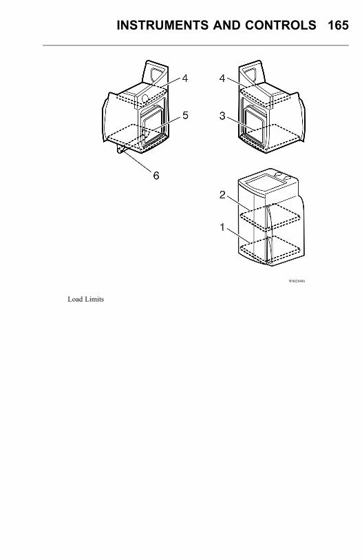
INSTRUMENTS AND CONTROLS 165
W8028486
Load Limits
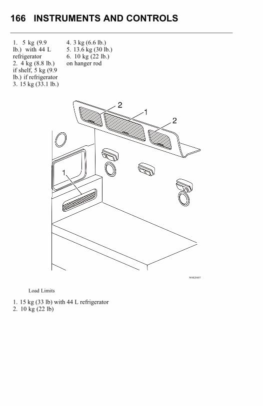
166 INSTRUMENTS AND CONTROLS
1. 5 kg (9.9lb.) with 44 Lrefrigerator2. 4 kg (8.8 lb.)if shelf, 5 kg (9.9lb.) if refrigerator3. 15 kg (33.1 lb.)
4. 3 kg (6.6 lb.)5. 13.6 kg (30 lb.)6. 10 kg (22 lb.)on hanger rod
W8028487
Load Limits
1. 15 kg (33 lb) with 44 L refrigerator2. 10 kg (22 lb)
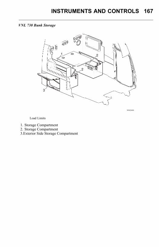
INSTRUMENTS AND CONTROLS 167
VNL 730 Bunk Storage
W8028488
Load Limits
1. Storage Compartment2. Storage Compartment3.Exterior Side Storage Compartment
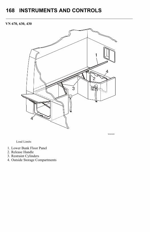
168 INSTRUMENTS AND CONTROLS
VN 670, 630, 430
W8028489
Load Limits
1. Lower Bunk Floor Panel2. Release Handle3. Restraint Cylinders4. Outside Storage Compartments
INSTRUMENTS AND CONTROLS 169
SLEEPER BUNKSGeneral
Upper and lower bunks are available in the VN 780, 730, 670 and 630 models. Thelower bunk is standard while the upper bunk is optional. The VN 430 are equippedwith one lower bunk.The bunks for the VN 670, 630, 430 cover the luggage compartment. They are hingedfor access to luggage from inside of the cab.To gain access, release the latch mechanism and lift by the edge of the bunk platform.Gas springs aid in opening and closing the platform in some models.The upper bunks for the VN 780, 670 and 630 may also be hinged (optional), and canbe raised out of the way. The VN 670 and VN 630 use the safety bunk harness latchto hold up the bunk. The VN 780 has latches on both sides of the wall that hold thebunk in position. To release the latches, pull the latch strap in the middle of the bunkunderside.When the bunk is raised and latched, make sure that the latches on both sides close
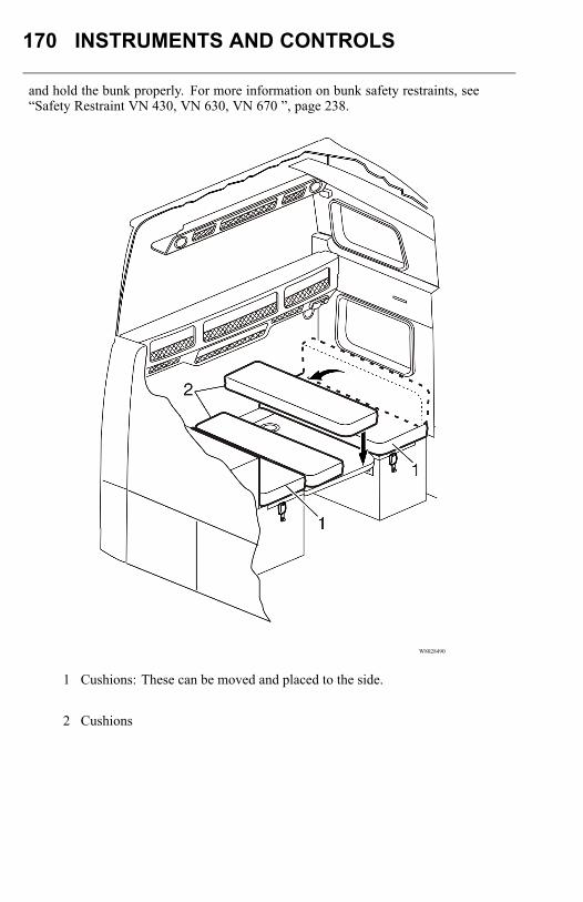
170 INSTRUMENTS AND CONTROLS
and hold the bunk properly. For more information on bunk safety restraints, see“Safety Restraint VN 430, VN 630, VN 670 ”, page 238.
W8028490
1 Cushions: These can be moved and placed to the side.
2 Cushions

INSTRUMENTS AND CONTROLS 171
VN 780 Sleeper Upper Bunk
DANGER
Always have three limbs (one foot andtwo hands or two feet and one hand)in contact with the floor, bunk or stepat all times when entering or exitingthe upper bunk. Failure to follow thisprocedure can lead to a fall and causesevere personal injury or death.
WARNING
Support the bunk with one hand whilereleasing the latches. Failure to supportthe bunk may lead to the bunk fallingwithout control, causing personal injury.
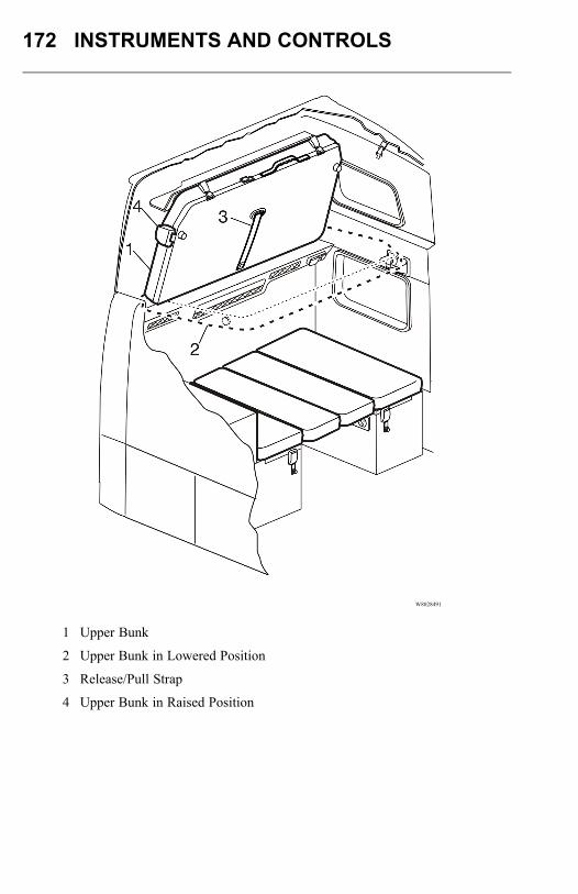
172 INSTRUMENTS AND CONTROLS
W8028491
1 Upper Bunk
2 Upper Bunk in Lowered Position
3 Release/Pull Strap
4 Upper Bunk in Raised Position
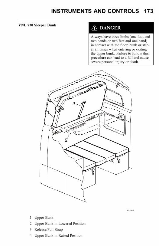
INSTRUMENTS AND CONTROLS 173
VNL 730 Sleeper BunkDANGER
Always have three limbs (one foot andtwo hands or two feet and one hand)in contact with the floor, bunk or stepat all times when entering or exitingthe upper bunk. Failure to follow thisprocedure can lead to a fall and causesevere personal injury or death.
W8028491
1 Upper Bunk2 Upper Bunk in Lowered Position3 Release/Pull Strap4 Upper Bunk in Raised Position
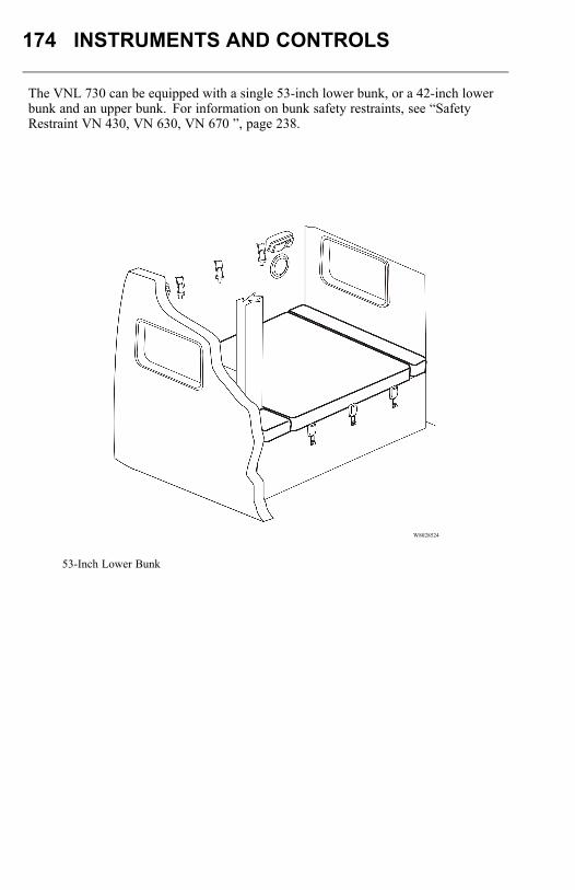
174 INSTRUMENTS AND CONTROLS
The VNL 730 can be equipped with a single 53-inch lower bunk, or a 42-inch lowerbunk and an upper bunk. For information on bunk safety restraints, see “SafetyRestraint VN 430, VN 630, VN 670 ”, page 238.
W8028524
53-Inch Lower Bunk
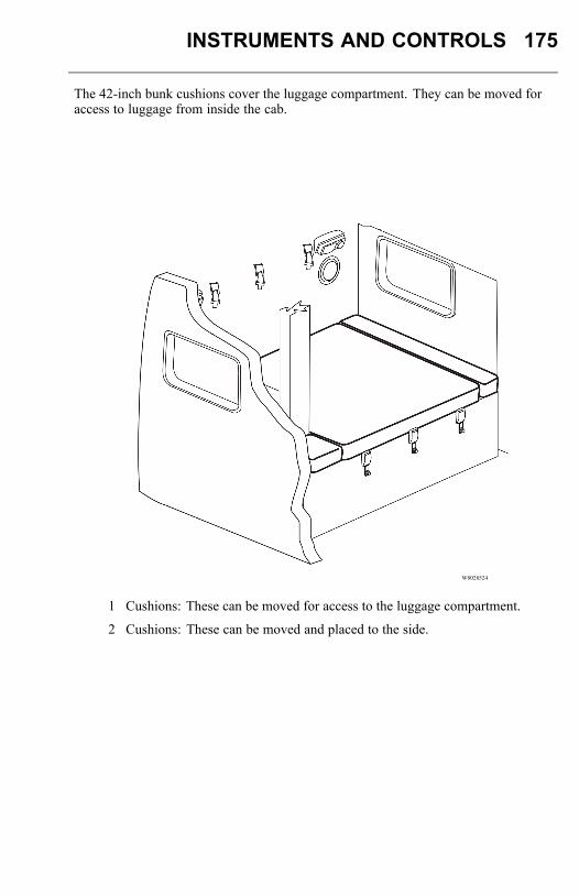
INSTRUMENTS AND CONTROLS 175
The 42-inch bunk cushions cover the luggage compartment. They can be moved foraccess to luggage from inside the cab.
W8028524
1 Cushions: These can be moved for access to the luggage compartment.
2 Cushions: These can be moved and placed to the side.
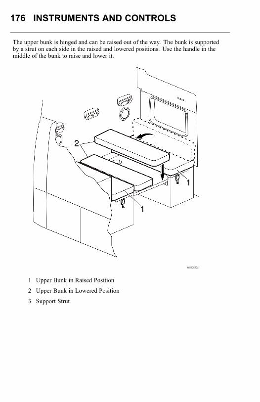
176 INSTRUMENTS AND CONTROLS
The upper bunk is hinged and can be raised out of the way. The bunk is supportedby a strut on each side in the raised and lowered positions. Use the handle in themiddle of the bunk to raise and lower it.
W8028525
1 Upper Bunk in Raised Position
2 Upper Bunk in Lowered Position
3 Support Strut
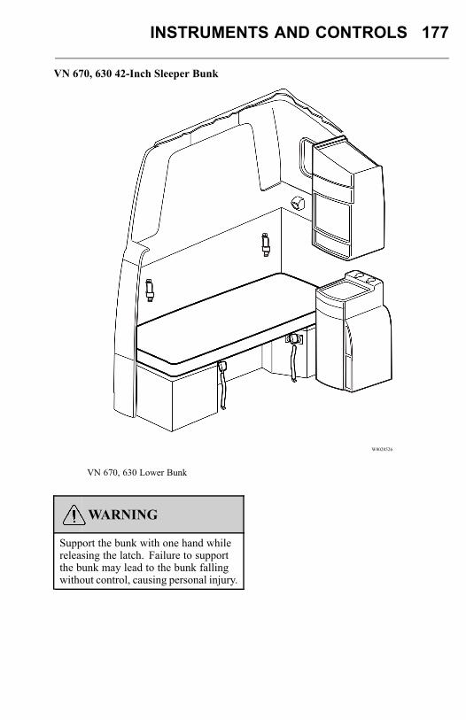
INSTRUMENTS AND CONTROLS 177
VN 670, 630 42-Inch Sleeper Bunk
W8028526
VN 670, 630 Lower Bunk
WARNING
Support the bunk with one hand whilereleasing the latch. Failure to supportthe bunk may lead to the bunk fallingwithout control, causing personal injury.
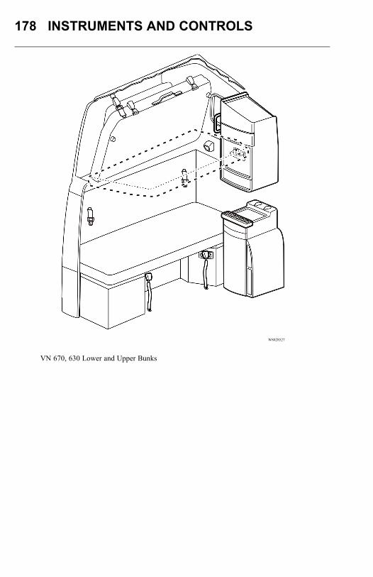
178 INSTRUMENTS AND CONTROLS
W8028527
VN 670, 630 Lower and Upper Bunks
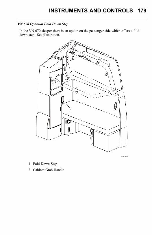
INSTRUMENTS AND CONTROLS 179
VN 670 Optional Fold Down Step
In the VN 670 sleeper there is an option on the passenger side which offers a folddown step. See illustration.
W8028528
1 Fold Down Step
2 Cabinet Grab Handle
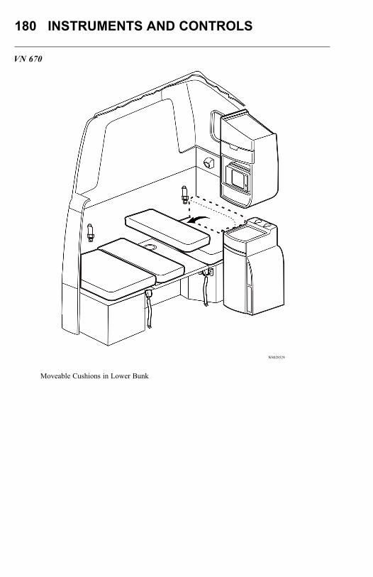
180 INSTRUMENTS AND CONTROLS
VN 670
W8028529
Moveable Cushions in Lower Bunk
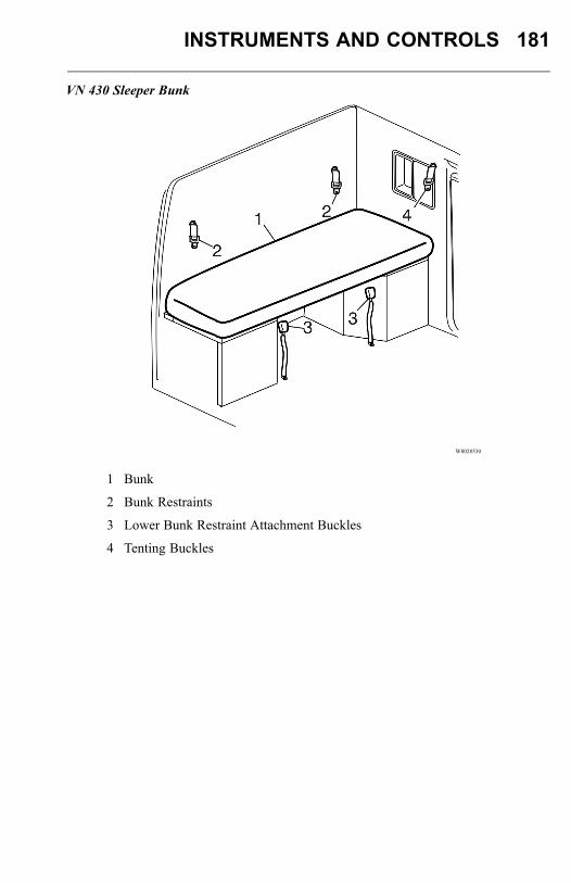
INSTRUMENTS AND CONTROLS 181
VN 430 Sleeper Bunk
W8028530
1 Bunk
2 Bunk Restraints
3 Lower Bunk Restraint Attachment Buckles
4 Tenting Buckles
182 INSTRUMENTS AND CONTROLS
Upper Bunk Access VN 780
DANGER
Always have three limbs (one foot andtwo hands or two feet and one hand)in contact with the floor, bunk or stepat all times when entering or exitingthe upper bunk. Failure to follow thisprocedure can lead to a fall and causesevere personal injury or death.
WARNING
Support the ladder with one hand whilereleasing the lock straps. Failure tosupport the ladder may lead to theladder falling out, causing injury to legor foot.
Access to the upper bunk is provided by lowering foldable ladder and securing theladder into the floor locator (6) and retainer bracket (2) in the upper bunk.The ladder stored in its collapsed position behind the passenger side cabinet. Torelease the ladder, unsnap the lock straps. Support the ladder so it does not fall outunaided.To access the upper bunk, start the climb by grabbing the grab handles with bothhands. Place the right foot on the bunk bottom to the right of the cabinet and the leftfoot on the upper step. Put both feet on the upper step and move the right hand to theupper bunk for support. Swing the upper body into the bunk and sit down.The grab handle for upper bunk access is located on the cabinet.
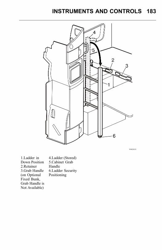
INSTRUMENTS AND CONTROLS 183
W8028531
1.Ladder inDown Position2.Retainer3.Grab Handle(on OptionalFixed Bunk,Grab Handle isNot Available)
4.Ladder (Stored)5.Cabinet GrabHandle6.Ladder SecurityPositioning
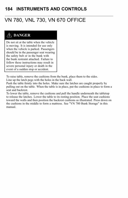
184 INSTRUMENTS AND CONTROLS
VN 780, VNL 730, VN 670 OFFICE
DANGER
Do not sit at the table when the vehicleis moving. It is intended for use onlywhen the vehicle is parked. Passengersshould be in the passenger seat wearingthe safety belt or in the bunk withthe bunk restraint attached. Failure tofollow these instructions may result insevere personal injury or death in theevent of a sudden stop or accident.
To raise table, remove the cushions from the bunk, place them to the sides.Line up the latch pegs with the holes in the back wall.Push the table firmly into the holes. Make sure the latches are caught properly bypulling out on the table. When the table is in place, put the cushions in place to form aseat and backrest.To lower the table, remove the cushions and pull the handle underneath the tabletopto release the latches. Lower the table to its resting position. Place the seat cushionstoward the walls and then position the backrest cushions as illustrated. Press down onthe cushions in the middle to form a mattress. See "VN 780 Bunk Storage" in thismanual.
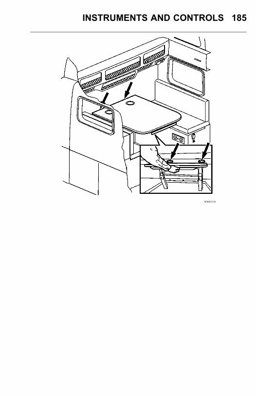
INSTRUMENTS AND CONTROLS 185
W8003158
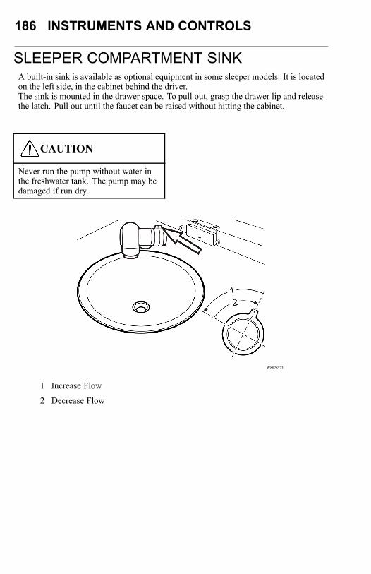
186 INSTRUMENTS AND CONTROLS
SLEEPER COMPARTMENT SINKA built-in sink is available as optional equipment in some sleeper models. It is locatedon the left side, in the cabinet behind the driver.The sink is mounted in the drawer space. To pull out, grasp the drawer lip and releasethe latch. Pull out until the faucet can be raised without hitting the cabinet.
CAUTION
Never run the pump without water inthe freshwater tank. The pump may bedamaged if run dry.
W8028573
1 Increase Flow
2 Decrease Flow
INSTRUMENTS AND CONTROLS 187
To operate the water pump, there is a combined valve and switch in the knob (seearrow in illustration) on the base. Turn the knob slightly toward you to start the pump;see arrow in illustration. Turn the knob further to increase water flow. When the knobis turned fully back to rest position, the pump will stop.
CAUTION
Make sure the pump is turned off beforepushing the drawer in. If the pumpcontinues to deliver water, overflowingwater can flood the cab floor.
In the bottom of the sink there is a spring-loaded drain plug that is sealed bypressing down and twisting clockwise. To release for letting water drain off, turncounterclockwise and the spring will lift the plug and open the drain.
Fresh Water Tank
Water is drawn from the fresh water tank (1) located beside the waste water tank (2) inthe left-hand side luggage compartment. Refill fresh water tank with potable drinkingwater only. Tank volume is 9 gallons (34 liters). On top of the tank is a hose (3) thatserves as a filler and a vent tube. In the bottom of the tank is a drain valve (4), with ahose attached, for draining the tank to the outside.
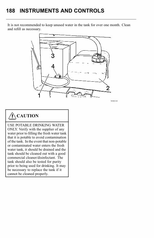
188 INSTRUMENTS AND CONTROLS
It is not recommended to keep unused water in the tank for over one month. Cleanand refill as necessary.
W8002168
CAUTION
USE POTABLE DRINKING WATERONLY. Verify with the supplier of anywater prior to filling the fresh water tankthat it is potable to avoid contaminationof the tank. In the event that non-potableor contaminated water enters the freshwater tank, it should be drained and thetank should be cleaned out with a goodcommercial cleaner/disinfectant. Thetank should also be tested for purityprior to being used for drinking. It maybe necessary to replace the tank if itcannot be cleaned properly.

INSTRUMENTS AND CONTROLS 189
CAUTION
Fresh water and waste water tanksmust be drained if the vehicle is notbeing used and the outside temperatureis below freezing. Also drain thehose from the pump to the faucet.Failure to drain the system may resultin component damage due to waterforming ice.
To fill the fresh water tank, unscrew the fill hose from the elbow fitting and removethe fill cap (5) from the tank. The fill hose is connected to a hose with a gardenhose-type fitting. Before turning the water on, turn the valve handle (6) to close thevalve (see lower illustration). When the end of the fill hose is inserted in the waterreservoir, open the valve slowly to fill. The valve is fully open when the handle isparallel with the hose.
W8028577
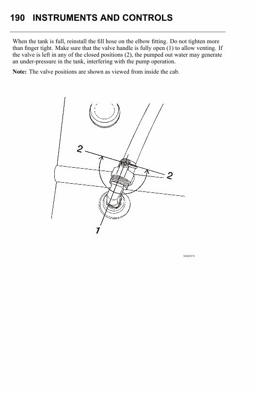
190 INSTRUMENTS AND CONTROLS
When the tank is full, reinstall the fill hose on the elbow fitting. Do not tighten morethan finger tight. Make sure that the valve handle is fully open (1) to allow venting. Ifthe valve is left in any of the closed positions (2), the pumped out water may generatean under-pressure in the tank, interfering with the pump operation.
Note: The valve positions are shown as viewed from inside the cab.
W8028578
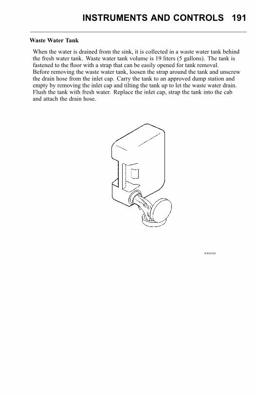
INSTRUMENTS AND CONTROLS 191
Waste Water Tank
When the water is drained from the sink, it is collected in a waste water tank behindthe fresh water tank. Waste water tank volume is 19 liters (5 gallons). The tank isfastened to the floor with a strap that can be easily opened for tank removal.Before removing the waste water tank, loosen the strap around the tank and unscrewthe drain hose from the inlet cap. Carry the tank to an approved dump station andempty by removing the inlet cap and tilting the tank up to let the waste water drain.Flush the tank with fresh water. Replace the inlet cap, strap the tank into the caband attach the drain hose.
W8028580
192 OPERATION
PRE-TRIP INSPECTION AND DAILYMAINTENANCE
DANGER
Before working on or inspecting avehicle, set the parking brakes, placethe transmission in neutral and blockthe wheels. Failure to do so can result inunexpected vehicle movement and cancause serious personal injury or death.
Safety is the most important and obvious reason for doing a pre-trip inspection.Federal and state laws require inspection performed by the driver. Federal and stateinspectors also inspect commercial vehicles. An unsafe vehicle can be placed "outof service" until the driver or owner corrects the deficiency. Owners and operatorsshould familiarize themselves with sections 49 CFR 396.11 and 396.13 concerningFederal requirements for vehicle inspection. Certain other laws may also apply.Section 49 CFR 396.13 states that all motor carrier drivers must complete a writtenreport at the end of each work day for each vehicle operated, covering most of what iscovered in the pre-trip list. The report should list all defects or deficiencies discoveredby the driver. A pre-trip inspection prepares for the end-of-work report.Starting on the next page are suggested guidelines to be used in performing truck,tractor and trailer pre-trip inspections. Depending on the application of the vehiclebeing used, these guidelines should be modified to include other necessary inspectionpoints. For example, steps and grab handles should be checked daily on refuse trucksbecause the operator is getting in and out of the cab more frequently.If any component or system does not pass this inspection, it must be corrected beforeoperating the vehicle. Whenever equipment requires adjustment, replacement, repairor lubrication, refer to the Service Manuals or contact an authorized Volvo Truckdealer for the correct procedures, specifications and intervals.Also, available through the vehicles driver information display (DID) is a pre-tripinspection system that will assist in performing the manual pre-trip inspection.
Pre-Trip AssistanceThe Pre-Trip Assistance option is a tool to assist the driver in completing the pre-tripinspection of the vehicle. This option is not a substitute for a complete pre-tripinspection. If any system of the vehicle does not pass inspection, the error must becorrected before operating the vehicle.The available pre-trip tests include a Switch/Circuit Status check, Exterior LightInspection check, and a Air Leakage check.
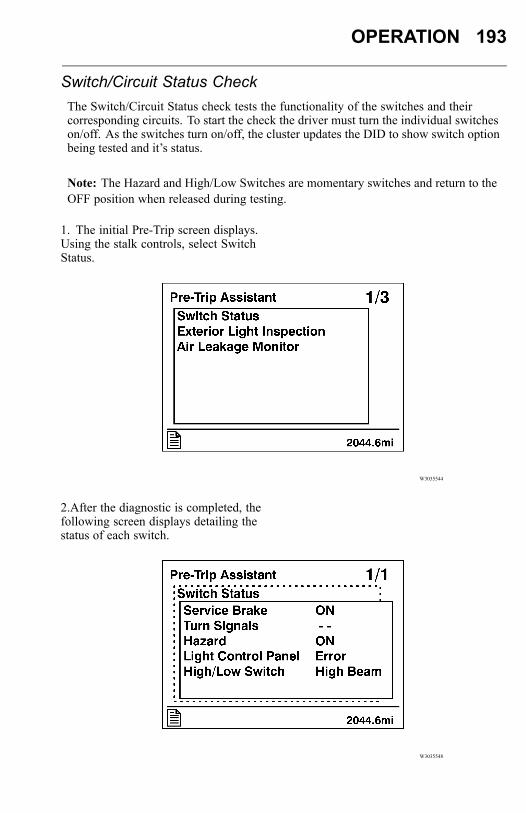
OPERATION 193
Switch/Circuit Status CheckThe Switch/Circuit Status check tests the functionality of the switches and theircorresponding circuits. To start the check the driver must turn the individual switcheson/off. As the switches turn on/off, the cluster updates the DID to show switch optionbeing tested and it’s status.
Note: The Hazard and High/Low Switches are momentary switches and return to theOFF position when released during testing.
1. The initial Pre-Trip screen displays.Using the stalk controls, select SwitchStatus.
W3035544
2.After the diagnostic is completed, thefollowing screen displays detailing thestatus of each switch.
W3035548
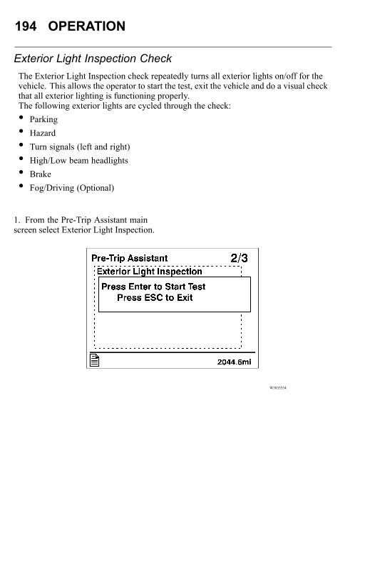
194 OPERATION
Exterior Light Inspection CheckThe Exterior Light Inspection check repeatedly turns all exterior lights on/off for thevehicle. This allows the operator to start the test, exit the vehicle and do a visual checkthat all exterior lighting is functioning properly.The following exterior lights are cycled through the check:• Parking• Hazard• Turn signals (left and right)• High/Low beam headlights• Brake• Fog/Driving (Optional)
1. From the Pre-Trip Assistant mainscreen select Exterior Light Inspection.
W3035554

OPERATION 195
2. The Test Started screen displays. Youcan stop the test by pressing ’ESC’ on thestalk or by starting the ignition.
W3035557
Once the test is started all exterior lightsflash on and off so that you can performa visual check.
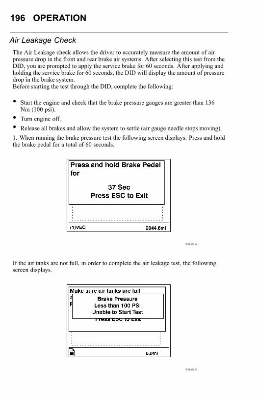
196 OPERATION
Air Leakage CheckThe Air Leakage check allows the driver to accurately measure the amount of airpressure drop in the front and rear brake air systems. After selecting this test from theDID, you are prompted to apply the service brake for 60 seconds. After applying andholding the service brake for 60 seconds, the DID will display the amount of pressuredrop in the brake system.Before starting the test through the DID, complete the following:
• Start the engine and check that the brake pressure gauges are greater than 136Nm (100 psi).
• Turn engine off.• Release all brakes and allow the system to settle (air gauge needle stops moving).1. When running the brake pressure test the following screen displays. Press and holdthe brake pedal for a total of 60 seconds.
W3035558
If the air tanks are not full, in order to complete the air leakage test, the followingscreen displays.
W3035559
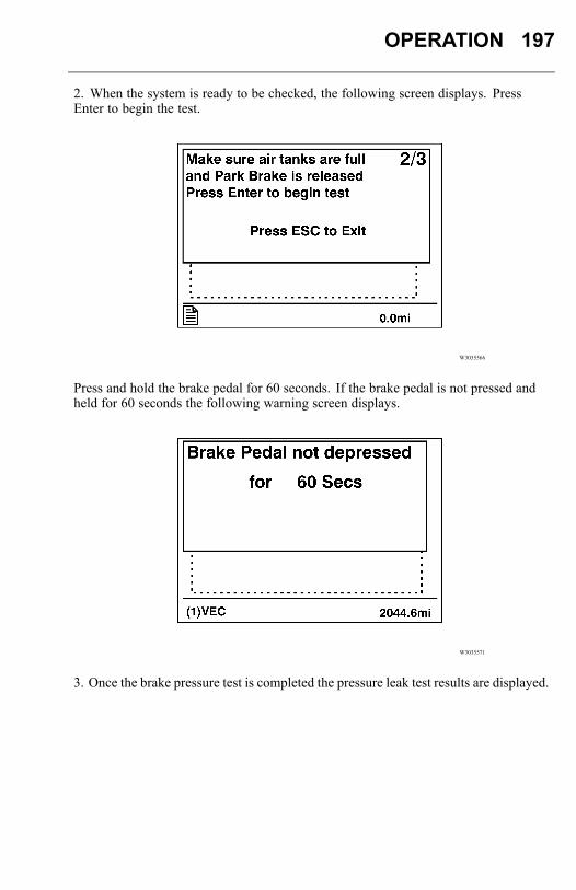
OPERATION 197
2. When the system is ready to be checked, the following screen displays. PressEnter to begin the test.
W3035566
Press and hold the brake pedal for 60 seconds. If the brake pedal is not pressed andheld for 60 seconds the following warning screen displays.
W3035571
3. Once the brake pressure test is completed the pressure leak test results are displayed.
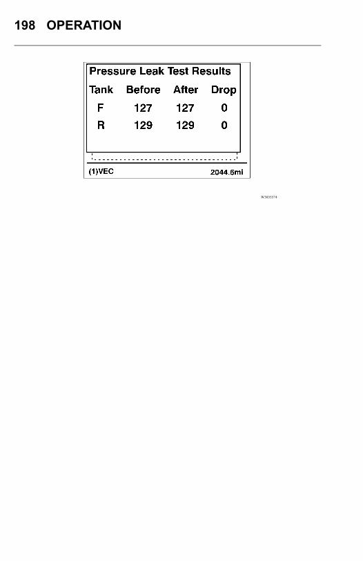
198 OPERATION
W3035574

OPERATION 199
Take your time going through the pre-trip inspection. Remember that a careful pre-tripinspection saves time by eliminating unscheduled stops for correcting a faulty item.The following information has been provided by the American Trucking Associationas developed by the D.O.T. Office of Motor Carriers (BMCS).
Pre-Trip Inspection Quick List
W0001230
VN
Pre-Trip Inspection Quick ListInspect the vehicle in a circular manner.
Approaching the Vehicle
• Check under the vehicle for oil, fuel, coolant leaks or other signs of damage.
• Check body surfaces for signs of breaks or damage.
Preparation
• Open drain cocks on air tanks to let the tanks drain.
• Chock wheels on vehicle and, if hooked up, trailer.
• Close air tank drain cocks.
• Start the engine and let the air pressure build up to normal. Stop enginecheck for air leaks.
• Switch on parking lights and hazard lights.
• Apply parking brakes. Listen for air leaks
200 OPERATION
• Raise cab so belts can be checked
Step 1: Left Side of the Cab
Left Front Wheel
• Check condition of wheel rim. Especially look for cracks, missing lockrings,bent or broken studs, missing clamps or lug nuts.
• Check condition of tire: properly inflated, no serious cuts, bulges, treadwear or any signs of misalignment; valve stem not touching wheel, rim orbrake drum; valve cap in place.
• Check wheel bearing and hub: no obvious leaking on outside or insidewheel. Verify correct oil level in hub.
Left Front Suspension
• Check condition of spring, spring hangers, shackles, U-bolts: no cracks,breaks or shifting.
• Check shock absorber condition.
Left Front Brake
• Condition of brake drum. With brakes released, look for a noticeable gapbetween lining and drum. (This check cannot be made if dust covers arein place.)
• Condition of brake air hose.
• Check brake chamber mounting bolts and bracket.
• Check slack adjuster and chamber pushrod travel for proper brakeadjustment.
Condition of Front Axle and Steering System, Left Side
• No loose, worn, bent, damaged or missing parts.
Engine Compartment, Left Side
• Check coolant hose condition.
• Check condition of fan drive belts.
• Check engine and surrounding areas for coolant, oil and fuel leaks.
• Check wiring harnesses for signs of damage.
OPERATION 201
Engine Compartment, Right Side
• Check condition of coolant and heater hoses.
• Check condition of fan drive belts.
• Check engine and surrounding areas for coolant, oil and fuel leaks.
• Check fuel separator sight glass and drain if necessary. Check for leaks.
• Check wiring harnesses for signs of damage.
• Check air filter with brackets and hoses for loose connections or damage.Check filter gauge, if mounted on the filter.
Step 2: Front of Cab Area
Condition of Windshield
• Check for damage and clean if dirty.
• Check windshield wiper arms for proper spring tension.
• Check wiper blades for any damage, "dead" rubber and attachment to arm.
Lights and Reflectors
• Lower cab and inspect parking, clearance and identification lights on cab.They should be clean, operating and of the proper color.
• Reflectors clean and proper color.
• Turn on headlights. High and low beams should be operating and lensesclean. If equipped, check daytime running lights.
• Left and right front turn signal lights clean, operating and proper color.
Grille
• Check that charge air cooler and radiator or bugscreens are clean andundamaged.
Step 3: Right Side of Cab Area
Right Front Wheel
• Check condition of wheel rim. Especially look for cracks, missing lockrings,bent or broken studs, missing clamps or lug nuts.
202 OPERATION
• Check condition of tire: properly inflated, no serious cuts, bulges, treadwear or any signs of misalignment; valve stem not touching wheel, rim orbrake drum; valve cap in place.
• Check wheel bearing and hub: no obvious leaking on outside or insidewheel. Verify correct oil level in hub.
Right Front Suspension
• Check condition of spring, spring hangers, shackles, U-bolts: no cracks,breaks or shifting.
• Shock absorber condition.
Right Front Brake
• Condition of brake drum. With brakes released, look for a noticeable gapbetween lining and drum. (This check cannot be made if dust covers arein place.)
• Condition of brake air hose: check for any chafing.
• Check brake chamber mounting bolts and bracket.
• Check slack adjuster and chamber pushrod travel. With brakes appliedor released, look for conspicuously different positions of the slack adjustersfor proper brake adjustment..
Condition of Front Axle and Steering System, Right Side
• No loose, worn, bent, damaged or missing parts.
Step 4: Right Saddle Tank Area
Right Fuel Tank(s)
• Securely mounted Diesel and Diesel Exhaust Fluid are not damaged orleaking.
• Fuel lines secure and not leaking. Check that shut-off valves are open.
• Tank(s) full of fuel. Cap on and secure.
Condition of Visible Components
• Rear of engine: not leaking.
• Transmission: not leaking. If equipped with oil cooler, check cooler, hosesand fittings for leaks.
OPERATION 203
• Check drive shaft.
• Exhaust system: secure, not leaking, not touching wires, fuel or air tubing.
• Frame and cross members: no bends, cracks or breaks.
DPF/SCR check hoses and fittings for leaks.
• Air tubing and electrical wiring: secured against snagging and chafing.
Step 5: Right Rear Vehicle Area
Dual Wheels, One or Two Axles
• Check condition of wheels and rims. Especially look for cracks, missinglockrings, bent or broken spacers, studs, missing clamps or lug nuts.
• Check condition of tires: properly inflated, no serious cuts, bulges, treadwear or any signs of misalignment; valve stems not touching wheels, rims orbrake drums; valve caps in place and no objects stuck between the wheels.
• Check that both tires are of same type, for example, not mixed radial andbias type and that their circumferences are matched.
• Check wheel bearing and hub: no obvious leaking on outside or inside wheel.
Suspension
• Check condition of springs (leaf), spring hangers, shackles and U-bolts.
• Axle alignment.
Brakes
• Condition of brake drums. With brakes released, look for a noticeable gapbetween lining and drum. (This check cannot be made if dust covers arein place.)
• Condition of brake hoses: check for any chafing.
• Check brake chamber mounting bolts and brackets.
• Check slack adjusters and chamber push rod travel. With brakes appliedor released, look for conspicuously different positions of the slack adjustersfor proper adjustment.
• Check spring brakes.
Step 6: Rear of Vehicle Area
Frame Area
• Frame or cross members not bent, cracked or otherwise damaged or missing.
204 OPERATION
• Check that air tubing and electrical lines are properly secured to the framewith no damage or chafing.
Lights and Reflectors
• Tail lights, brake lights and turn signal lights: operating, clean and propercolor.
Step 7: Coupling System Area
Fifth Wheel
• Securely mounted to the frame.
• No missing or damaged parts.
• Check that trunnion and plate are properly lubricated.
Sliding Fifth Wheel
• Mechanism not worn, bent, damaged or parts missing.
• Properly lubricated.
• All locking pins present and locked in place.
• If air operated: no air leaks.
Air Tubing and Electric Lines Visible From This Point
• Should be secure from dangling.
• Both air lines and electric line should be free from damage, oil and grease.
Step 8: Left Saddle Tank and Left Rear Vehicle Wheels Area
Dual Wheels, One or Two Axles
• Check condition of wheels and rims. Especially look for cracks, missinglockrings, bent or broken spacers, studs, missing clamps or lug nuts.
• Check condition of tires: properly inflated, no serious cuts, bulges, treadwear or any signs of misalignment; valve stems not touching wheels, rims orbrake drums; valve caps in place and no objects stuck between the wheels.
• Check that both tires are of same type, for example, not mixed radial andbias type and that their circumferences are matched.
• Check wheel bearing and hub: no obvious leaking on outside or inside wheel.
OPERATION 205
Suspension
• Check condition of springs (leaf or air), spring hangers, shackles and U-bolts,no cracks, breaks or shifting.
Brakes
• Condition of brake drums. With brakes released, look for a noticeable gapbetween lining and drum. (This check cannot be made if dust covers arein place.)
• Condition of brake hoses: check for any chafing.
• Check brake chamber mounting bolts and brackets.
• Check slack adjusters and chamber push rod travel. With brakes appliedor released, look for conspicuously different positions of the slack adjustersfor proper brake adjustment..
• Check spring brakes.
Condition of Visible Components
• Transmission: not leaking.
• Drive shaft: looks OK.
• Exhaust system: secure, not leaking, not touching wires, fuel or air tubing.
• Frame and cross members: no bends, cracks or breaks.
• Air tubing and electrical wiring: secured against snagging and chafing.
Left Fuel Tank(s)
• Securely mounted and not damaged or leaking.
• Fuel lines secure and not leaking. Check that shut-off valves are open.
• Tank(s) full of fuel. Cap on and secure.
Battery Area
• Open the battery box. Battery box securely mounted to vehicle.
• Batteries secured against movement.
• Battery cases not broken or leaking. Battery cables free from damage.
• Tops of batteries and terminals clean and free from foreign material.
• If equipped, replace battery lid and make sure it is securely fastened.
206 OPERATION
In the Cab
• Check steps and grab handles for looseness or breakage. Also, cleanthem if there is any substance that makes them slippery, which makes cabentry/exit hazardous.
• Start the engine. If equipped, check that exhaust rain cap opens whenaccelerating engine.
• Check gauges and tell-tale light function. See the Instruments and Controlssection.
• Check function of low air warning.
• Check clutch function. If equipped, check for clutch brake function.
• Check windshield wipers and washers and horns, including back-up alarm,if equipped.
• Clean inside windshield, door windows and instruments. Clean mirrors.
• Check temperature control and defroster. If equipped, check mirror heater.
• Check condition of warning triangles, fire extinguisher and flares.
• Adjust the seat. Check mirror adjustment.
• Check safety belts for function and damage.
• Apply service brakes. After initial drop, pressure should hold steady, orincrease slightly, with engine at idle.
• Check steering wheel for excessive free play.
• Check for loose items in the cab. Secure them if necessary.
Hooking Up To Trailer
Hook-Up Preparation
• Check kingpin and mounting plate on trailer, free from wear, bends ordamage.
• Chock trailer wheels.
Fifth Wheel or Trailer Hitch
• No visible space between fifth wheel and trailer.
• Locking jaws around the shank and not the head of kingpin.
• Release lever properly seated and safety latch/lock engaged.
• Check all connections to dolly or trailer hitch and safety chains are secured.
• Check function of trailer air supply valve and trailer brakes.
OPERATION 207
Sliding Fifth Wheel
• Check that fifth wheel is not so far forward that the tractor frame will strikethe landing gear during turns.
Note: Refer to the trailer manufacturer’s manual for specific information on thetrailer checks.
Step 9: Trailer Front Area
Air and Electrical Connections
• Glad hands properly mounted, free from damage and not leaking.
• Trailer cord receptacle properly mounted, free of damage; plug properlyseated and safety catch engaged to prevent accidental disconnect.
• Air and electrical lines properly secured against tangling, snagging andchafing with sufficient slack for turns.
Step 10: Right Side of Trailer Area
Landing Gear or Dolly Area
• Fully raised; no missing or damaged parts.
• Crank handle present and secured.
• If power operated, no air/hydraulic leaks.
Spare Wheel(s)
• Carrier or rack not damaged.
• Spare wheel securely mounted in rack.
• Tire and wheel condition adequate for a spare: proper size, properly inflated.
Lights and Reflectors
• Trailer side clearance lights: clean, operating and proper color.
• Reflectors clean and proper color.
Frame and Body
• Frame and crossmembers not bent, cracked, damaged or missing.
• Proper placarding.
208 OPERATION
• Body parts not damaged or missing.
Step 11: Right Rear Trailer Wheel
Dual Wheels, One or Two Axles
• Check condition of wheels and rims. Especially look for cracks, missinglockrings, bent or broken spacers, studs, missing clamps or lug nuts.
• Check condition of tires: properly inflated, no serious cuts, bulges, treadwear or any signs of misalignment; valve stems not touching wheels, rims orbrake drums; valve caps in place and no objects stuck between the wheels.
• Check that both tires are of same type, for example, not mixed radial andbias type and that their circumferences are matched.
• Check wheel bearing and hub: no obvious leaking on outside or inside wheel.
Suspension
• Condition of springs (leaf or air), spring hangers, shackles and U-bolts.
• Axle alignment.
• Condition of torque rod arms.
• If equipped with sliding axles, check position and alignment. Look fordamaged, worn or missing parts, all locks present, fully in place and locked.
• Flexible air tubing not cracked, cut, crimped or otherwise damaged. Securedagainst tangling, dragging and chafing.
Brakes
• Condition of brake drums. With brakes released, look for a noticeable gapbetween lining and drum. (This check cannot be made if dust covers arein place.)
• Condition of brake hoses: check for any chafing.
• Check brake chamber mounting bolts and brackets.
• Check slack adjusters and chamber push rod travel. With brakes appliedor released, look for conspicuously different positions of the slack adjustersfor proper brake adjustment..
• Check spring brakes.
Step 12: Rear of Trailer Area
Lights and Reflectors
OPERATION 209
• Rear clearance, identification and tail lights clean, operating and proper color.
• Reflectors clean and proper color.
Cargo Securement
• Cargo properly blocked, braced, tied, chained, etc.
• Tailboard up and properly secured. End gates free from damage, properlysecured in stake pockets.
• Canvas or tarp (if required) properly latched down to prevent water damage,tearing, billowing or blockage of either mirrors or tail lights.
• Rear doors securely closed, latched or locked; required security seals inplace.
• Underside guard in place: not cracked, bent or broken.
Step 13: Left Rear Trailer Wheels Area
Dual Wheels, One or Two Axles
• Check condition of wheels and rims. Especially look for cracks, lockringsmissing, bent or broken spacers, studs, missing clamps or lug nuts.
• Check condition of tires: properly inflated, no serious cuts, bulges, treadwear or any signs of misalignment; valve stems not touching wheels, rims orbrake drums; valve caps in place and no objects stuck between the wheels.
• Check that both tires are of same type, for example, not mixed radial andbias type and that their circumferences are matched.
• Check wheel bearing and hub: no obvious leaking on outside or inside wheel.
Suspension
• Condition of springs (leaf or air), spring hangers, shackles and U-bolts.
• Axle alignment.
• Condition of torque rod arms.
• If equipped with sliding axles, check position and alignment. Look fordamaged, worn or missing parts, all locks present, fully in place and locked.
• Flexible air tubing not cracked, cut, crimped or otherwise damaged. It shouldbe secured against tangling, dragging and chafing.
Brakes
210 OPERATION
• Condition of brake drums. With brakes released, look for a noticeable gapbetween lining and drum. (This check can not be made if dust covers arein place.)
• Condition of brake hoses: check for any chafing.
• Check brake chamber mounting bolts and brackets.
• Check slack adjusters and chamber push rod travel. With brakes applied orreleased, look for conspicuously different positions of the slack adjusters.
• Check spring brakes.
Step 14: Left Side of Trailer Area
Landing Gear or Dolly Area
• Fully raised; no missing or damaged parts.
• Crank handle present and secured.
• If power operated, no air/hydraulic leaks.
Spare Wheel(s)
• Spare wheel securely mounted in rack with no damage to rack.
• Tire and wheel condition adequate for a spare: proper size, properly inflated.
Lights and Reflectors
• Trailer side clearance lights: clean, operating and proper color.
• Reflectors clean and proper color.
Frame and Body
• Frame and crossmembers not bent, cracked, damaged or missing.
• Proper placarding.
• Body parts not damaged or missing.
Before Leaving the Parking Area
• Remove chocks from the wheels.
• Test trailer hook-up by slowly pulling while applying the trailer brakes withthe trailer brake hand control valve.
OPERATION 211
• Test the service brakes before leaving the parking area.
• Test parking brakes by stopping on a 20% grade and applying the parkingbrakes. The parking brakes shall hold the combined vehicle and trailer withoutmoving.
New Vehicle Break-InTo ensure many years of reliable, trouble-free operation, the following break-inprocedures are recommended:
Note: Oil change, filter change and chassis lubrication are no longer required atthe 3,000-mile vehicle break-in interval.
Refer to the preventive maintenance schedules outlined in the Maintenanceand Lubrication Manual (21394653) for recommended lubrication changeintervals for the following items:
• Gear oils (transmission, rear axle carrier[s], front drive axle carrier, transfercase, flywheel PTO)
• Engine oil
• Oil filters
• Fuel filters
• Coolant conditioner
Note: It is important that components be filled with lubricants meeting thespecifications as given in the Maintenance and Lubrication Manual (21394653)
Note: When checking oil levels, the vehicle must be parked on level ground, andthe units at normal operating temperature. Components must be filled to the correctlevel. DO NOT OVERFILL.
Note: Oil and filter change intervals in this manual pertain to components built byVolvo Truck. For information concerning oil and oil filter change intervals for vendorcomponents, refer to the specific vendor component service literature.
During the First 5000 Kilometers (3000 Miles)
• After the first 200 km (125 miles), retorque the wheel nuts using an accuratelycalibrated torque wrench. Recheck this torque again after 800 km (500 miles).
• Check oil and coolant levels frequently.
• Check brake and clutch adjustments per recommended maintenanceschedule, and adjust as needed.
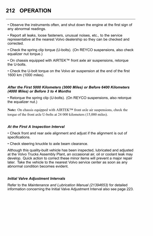
212 OPERATION
• Observe the instruments often, and shut down the engine at the first sign ofany abnormal readings.
• Report all leaks, loose fasteners, unusual noises, etc., to the servicerepresentative at the nearest Volvo dealership so they can be checked andcorrected.
• Check the spring clip torque (U-bolts). (On REYCO suspensions, also checkequalizer nut torque.)
• On chassis equipped with AIRTEK™ front axle air suspensions, retorquethe U-bolts.
• Check the U-bolt torque on the Volvo air suspension at the end of the first1600 km (1000 miles).
After the First 5000 Kilometers (3000 Miles) or Before 6400 Kilometers(4000 Miles) or Before 3 to 4 Months
• Retorque the spring clip (U-bolts). (On REYCO suspensions, also retorquethe equalizer nut.)
Note: On chassis equipped with AIRTEK™ front axle air suspensions, check thetorque of the front axle U-bolts at 24 000 kilometers (15,000 miles).
At the First A Inspection Interval
• Check front and rear axle alignment and adjust if the alignment is out ofspecifications.
• Check steering knuckle to axle beam clearance.
Although this quality-built vehicle has been inspected, lubricated and adjustedat the Volvo Trucks Assembly Plant, an occasional air, oil or coolant leak maydevelop. Quick action to correct these minor items will prevent a major repairlater. Take the vehicle to the nearest Volvo service center as soon as anyabnormal condition becomes evident.
Initial Valve Adjustment Intervals
Refer to the Maintenance and Lubrication Manual (21394653) for detailedinformation concerning the Initial Valve Adjustment Interval also see page 223.
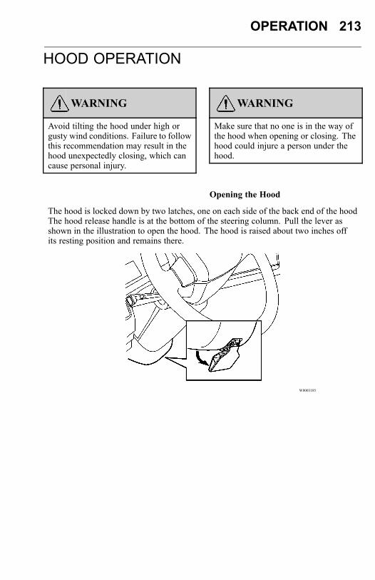
OPERATION 213
HOOD OPERATION
WARNING
Avoid tilting the hood under high orgusty wind conditions. Failure to followthis recommendation may result in thehood unexpectedly closing, which cancause personal injury.
WARNING
Make sure that no one is in the way ofthe hood when opening or closing. Thehood could injure a person under thehood.
Opening the Hood
The hood is locked down by two latches, one on each side of the back end of the hoodThe hood release handle is at the bottom of the steering column. Pull the lever asshown in the illustration to open the hood. The hood is raised about two inches offits resting position and remains there.
W8003185

214 OPERATION
Make sure the hood can be opened fully without hitting anything. There are twomethods for opening the hood.1. Stand in front of the hood with feet in line with the vehicle. Place feet well apartand grasp the recessed handle in the front part of the hood. Transfer the body weightby leaning away from the hood. Lift the hood until it is past the balance point. Releasethe hood and let it complete the opening movement unaided.
W8003113
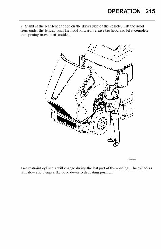
OPERATION 215
2. Stand at the rear fender edge on the driver side of the vehicle. Lift the hoodfrom under the fender, push the hood forward, release the hood and let it completethe opening movement unaided.
W8003546
Two restraint cylinders will engage during the last part of the opening. The cylinderswill slow and dampen the hood down to its resting position.
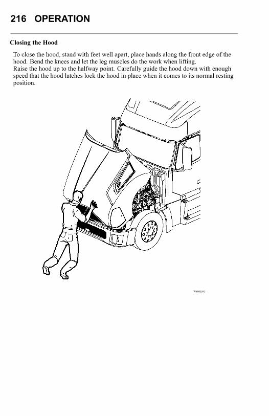
216 OPERATION
Closing the Hood
To close the hood, stand with feet well apart, place hands along the front edge of thehood. Bend the knees and let the leg muscles do the work when lifting.Raise the hood up to the halfway point. Carefully guide the hood down with enoughspeed that the hood latches lock the hood in place when it comes to its normal restingposition.
W8003543
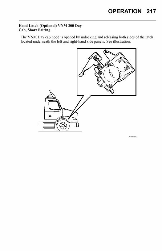
OPERATION 217
Hood Latch (Optional) VNM 200 DayCab, Short Fairing
The VNM Day cab hood is opened by unlocking and releasing both sides of the latchlocated underneath the left and right-hand side panels. See illustration.
W8003446
218 OPERATION
CHASSIS FAIRING/STEPS OPEN AND LOCKED POSITIONS
WARNING
Always check security of fairing andsteps before use. Ensure that the fairingis completely closed and the handles arein the locked position to prevent injuryfrom slip and fall.
The chassis fairing on the VN vehicle folds up and down for battery and air tankaccess.
CAUTION
DO NOT open fairing while the cabdoor is open. This can result in paintdamage on the fairing.
To open fairing: Rotate both handles to unlocked position, and pull fairing open.
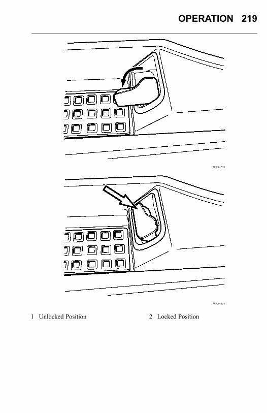
OPERATION 219
W5001359
W5001358
1 Unlocked Position 2 Locked Position
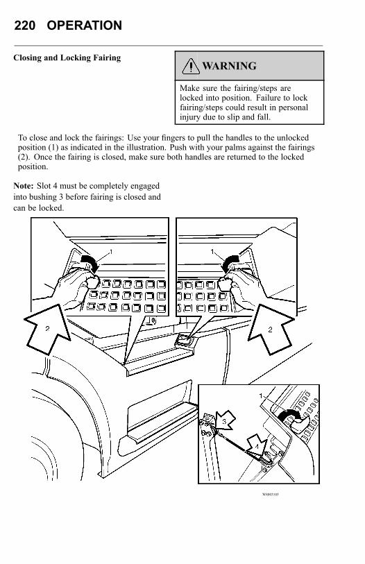
220 OPERATION
Closing and Locking FairingWARNING
Make sure the fairing/steps arelocked into position. Failure to lockfairing/steps could result in personalinjury due to slip and fall.
To close and lock the fairings: Use your fingers to pull the handles to the unlockedposition (1) as indicated in the illustration. Push with your palms against the fairings(2). Once the fairing is closed, make sure both handles are returned to the lockedposition.
Note: Slot 4 must be completely engagedinto bushing 3 before fairing is closed andcan be locked.
W8003105
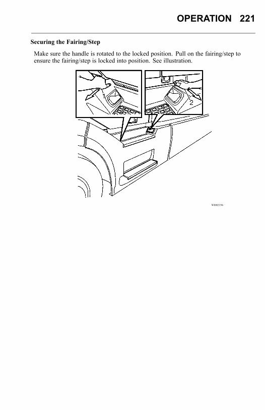
OPERATION 221
Securing the Fairing/Step
Make sure the handle is rotated to the locked position. Pull on the fairing/step toensure the fairing/step is locked into position. See illustration.
W8003196
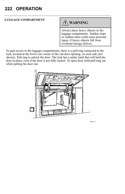
222 OPERATION
LUGGAGE COMPARTMENTWARNING
Always place heavy objects in theluggage compartment. Sudden stopsor sudden turns could cause personalinjury if heavy objects fall fromoverhead storage shelves.
To gain access to the luggage compartments, there is a pull-ring connected to thelock, located at the lower rear corner of the cab door opening, on each side (notshown). Pull ring to unlock the door. The lock has a safety latch that will hold thedoor in place, even if the door is not fully locked. To open door, hold pull-ring outwhile pulling the door out.
W8003124
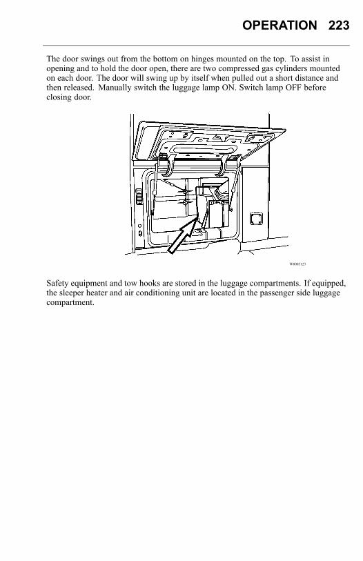
OPERATION 223
The door swings out from the bottom on hinges mounted on the top. To assist inopening and to hold the door open, there are two compressed gas cylinders mountedon each door. The door will swing up by itself when pulled out a short distance andthen released. Manually switch the luggage lamp ON. Switch lamp OFF beforeclosing door.
W8003123
Safety equipment and tow hooks are stored in the luggage compartments. If equipped,the sleeper heater and air conditioning unit are located in the passenger side luggagecompartment.
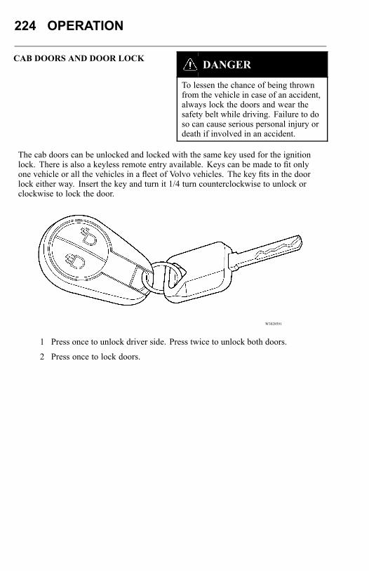
224 OPERATION
CAB DOORS AND DOOR LOCKDANGER
To lessen the chance of being thrownfrom the vehicle in case of an accident,always lock the doors and wear thesafety belt while driving. Failure to doso can cause serious personal injury ordeath if involved in an accident.
The cab doors can be unlocked and locked with the same key used for the ignitionlock. There is also a keyless remote entry available. Keys can be made to fit onlyone vehicle or all the vehicles in a fleet of Volvo vehicles. The key fits in the doorlock either way. Insert the key and turn it 1/4 turn counterclockwise to unlock orclockwise to lock the door.
W3028591
1 Press once to unlock driver side. Press twice to unlock both doors.
2 Press once to lock doors.
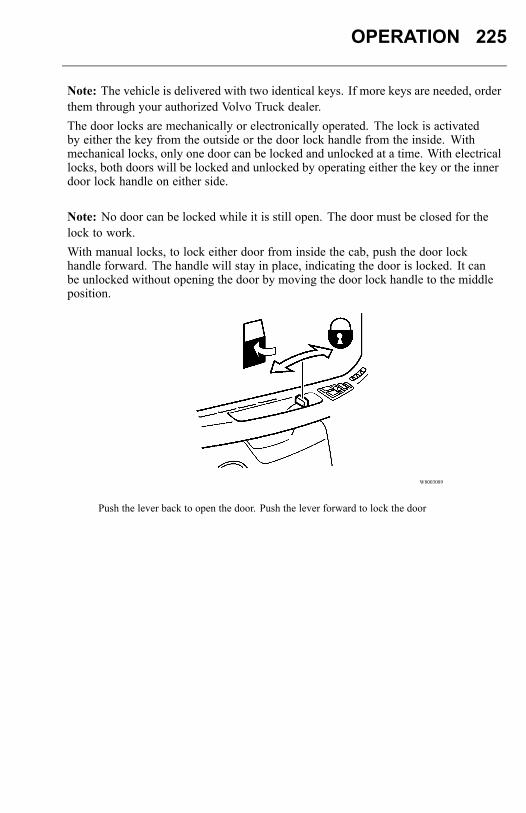
OPERATION 225
Note: The vehicle is delivered with two identical keys. If more keys are needed, orderthem through your authorized Volvo Truck dealer.The door locks are mechanically or electronically operated. The lock is activatedby either the key from the outside or the door lock handle from the inside. Withmechanical locks, only one door can be locked and unlocked at a time. With electricallocks, both doors will be locked and unlocked by operating either the key or the innerdoor lock handle on either side.
Note: No door can be locked while it is still open. The door must be closed for thelock to work.With manual locks, to lock either door from inside the cab, push the door lockhandle forward. The handle will stay in place, indicating the door is locked. It canbe unlocked without opening the door by moving the door lock handle to the middleposition.
W8003089
Push the lever back to open the door. Push the lever forward to lock the door
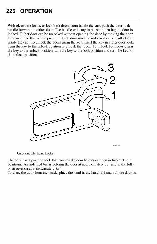
226 OPERATION
With electronic locks, to lock both doors from inside the cab, push the door lockhandle forward on either door. The handle will stay in place, indicating the door islocked. Either door can be unlocked without opening the door by moving the doorlock handle to the middle position. Each door must be unlocked individually frominside the cab. To unlock the doors using the key, insert the key in either door look.Turn the key to the unlock position to unlock that door. To unlock both doors, turnthe key to the unlock position, turn the key to the lock position and turn the key tothe unlock position.
W8028592
Unlocking Electronic Locks
The door has a position lock that enables the door to remain open in two differentpositions. An indented bar is holding the door at approximately 30° and in the fullyopen position at approximately 85°.To close the door from the inside, place the hand in the handhold and pull the door in.
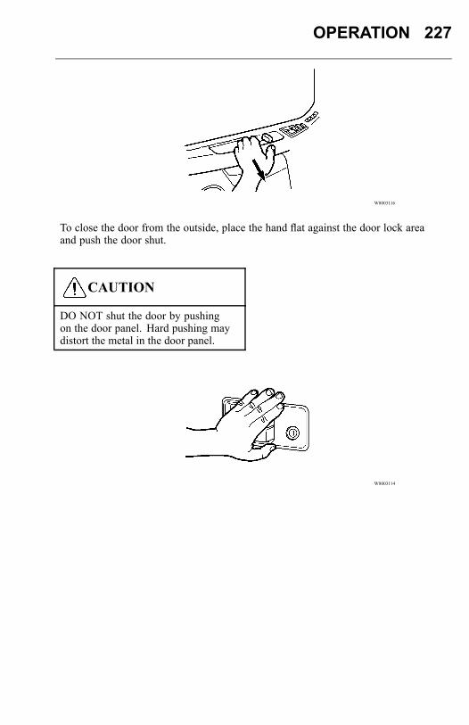
OPERATION 227
W8003116
To close the door from the outside, place the hand flat against the door lock areaand push the door shut.
CAUTION
DO NOT shut the door by pushingon the door panel. Hard pushing maydistort the metal in the door panel.
W8003114
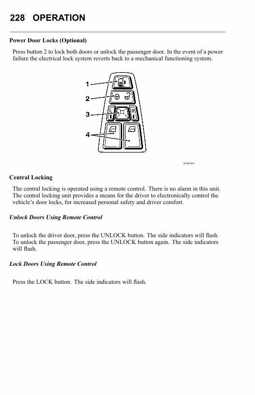
228 OPERATION
Power Door Locks (Optional)
Press button 2 to lock both doors or unlock the passenger door. In the event of a powerfailure the electrical lock system reverts back to a mechanical functioning system.
W8003087
Central Locking
The central locking is operated using a remote control. There is no alarm in this unit.The central locking unit provides a means for the driver to electronically control thevehicle’s door locks, for increased personal safety and driver comfort.
Unlock Doors Using Remote Control
To unlock the driver door, press the UNLOCK button. The side indicators will flash.To unlock the passenger door, press the UNLOCK button again. The side indicatorswill flash.
Lock Doors Using Remote Control
Press the LOCK button. The side indicators will flash.
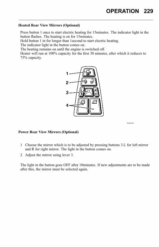
OPERATION 229
Heated Rear View Mirrors (Optional)
Press button 1 once to start electric heating for 15minutes. The indicator light in thebutton flashes. The heating is on for 15minutes.Hold button 1 in for longer than 1second to start electric heating.The indicator light in the button comes on.The heating remains on until the engine is switched off.Heater will run at 100% capacity for the first 30 minutes, after which it reduces to75% capacity.
W8003087
Power Rear View Mirrors (Optional)
1 Choose the mirror which is to be adjusted by pressing buttons 3.L for left mirrorand R for right mirror. The light in the button comes on.
2 Adjust the mirror using lever 3.
The light in the button goes OFF after 10minutes. If new adjustments are to be madeafter this, the mirror must be selected again.
230 OPERATION
Power Windows (Optional)Open Window (Auto-Down)
1 Depress the down position (2) on the button for 1second.2 Release the button.3 The window opens.
The window stops when it is completely open, when the down position (2) on thebutton is depressed again or when the up position (1) on the button is depressed.Make small adjustments with short pushes on the button.
Close Window
Depress the up position (1) on the button until the window is completely closed.
SAFETY BELTSGeneral
DANGER
Safety belts must be properly worn at alltimes by the driver and all passengerswhile the vehicle is in motion even if thevehicle is equipped with a SupplementalRestraint System (SRS or air bag).Failure to do so can result in seriouspersonal injury or death in the event ofa collision.
DANGER
Fasten the safety belt before starting todrive. Trying to fasten the safety beltwhile the vehicle is moving may leadto an accident, causing serious personalinjury or death.
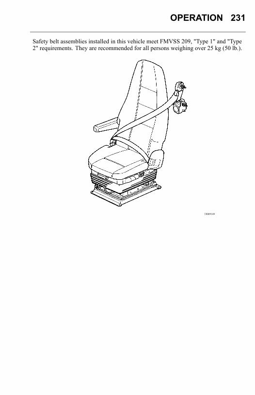
OPERATION 231
Safety belt assemblies installed in this vehicle meet FMVSS 209, "Type 1" and "Type2" requirements. They are recommended for all persons weighing over 25 kg (50 lb.).
T8009149
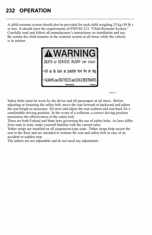
232 OPERATION
A child restraint system should also be provided for each child weighing 25 kg (50 lb.)or less. It should meet the requirements of FMVSS 213, "Child Restraint System."Carefully read and follow all manufacturer’s instructions on installation and use.Be certain the child remains in the restraint system at all times while the vehicleis in motion.
W8002741
Safety belts must be worn by the driver and all passengers at all times. Beforeadjusting or fastening the safety belt, move the seat forward or backward and adjustthe seat height as necessary. Sit erect and adjust the seat cushion and seat back for acomfortable driving position. In the event of a collision, a correct driving positionmaximizes the effectiveness of the safety belt.There are both Federal and State laws governing the use of safety belts. As laws differfrom state to state, make yourself familiar with the current rules.Tether straps are installed on all suspension-type seats. Tether straps help secure theseat to the floor and are intended to restrain the seat and safety belt in case of anaccident or sudden stop.The tethers are not adjustable and do not need any adjustment.
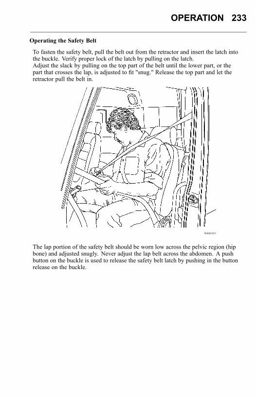
OPERATION 233
Operating the Safety Belt
To fasten the safety belt, pull the belt out from the retractor and insert the latch intothe buckle. Verify proper lock of the latch by pulling on the latch.Adjust the slack by pulling on the top part of the belt until the lower part, or thepart that crosses the lap, is adjusted to fit "snug." Release the top part and let theretractor pull the belt in.
W8001835
The lap portion of the safety belt should be worn low across the pelvic region (hipbone) and adjusted snugly. Never adjust the lap belt across the abdomen. A pushbutton on the buckle is used to release the safety belt latch by pushing in the buttonrelease on the buckle.
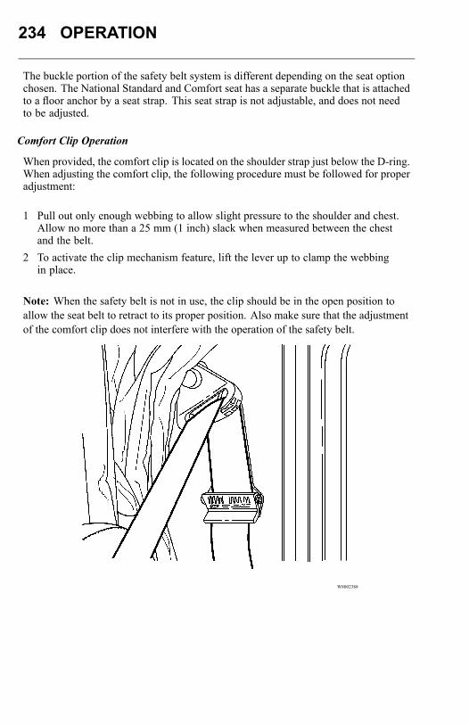
234 OPERATION
The buckle portion of the safety belt system is different depending on the seat optionchosen. The National Standard and Comfort seat has a separate buckle that is attachedto a floor anchor by a seat strap. This seat strap is not adjustable, and does not needto be adjusted.
Comfort Clip Operation
When provided, the comfort clip is located on the shoulder strap just below the D-ring.When adjusting the comfort clip, the following procedure must be followed for properadjustment:
1 Pull out only enough webbing to allow slight pressure to the shoulder and chest.Allow no more than a 25 mm (1 inch) slack when measured between the chestand the belt.
2 To activate the clip mechanism feature, lift the lever up to clamp the webbingin place.
Note: When the safety belt is not in use, the clip should be in the open position toallow the seat belt to retract to its proper position. Also make sure that the adjustmentof the comfort clip does not interfere with the operation of the safety belt.
W8002388
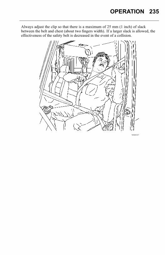
OPERATION 235
Always adjust the clip so that there is a maximum of 25 mm (1 inch) of slackbetween the belt and chest (about two fingers width). If a larger slack is allowed, theeffectiveness of the safety belt is decreased in the event of a collision.
W8001837
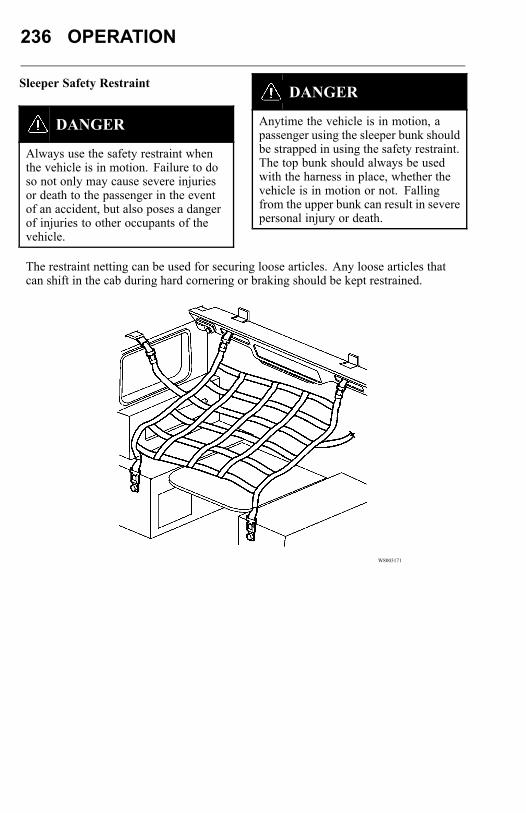
236 OPERATION
Sleeper Safety Restraint
DANGER
Always use the safety restraint whenthe vehicle is in motion. Failure to doso not only may cause severe injuriesor death to the passenger in the eventof an accident, but also poses a dangerof injuries to other occupants of thevehicle.
DANGER
Anytime the vehicle is in motion, apassenger using the sleeper bunk shouldbe strapped in using the safety restraint.The top bunk should always be usedwith the harness in place, whether thevehicle is in motion or not. Fallingfrom the upper bunk can result in severepersonal injury or death.
The restraint netting can be used for securing loose articles. Any loose articles thatcan shift in the cab during hard cornering or braking should be kept restrained.
W8003171
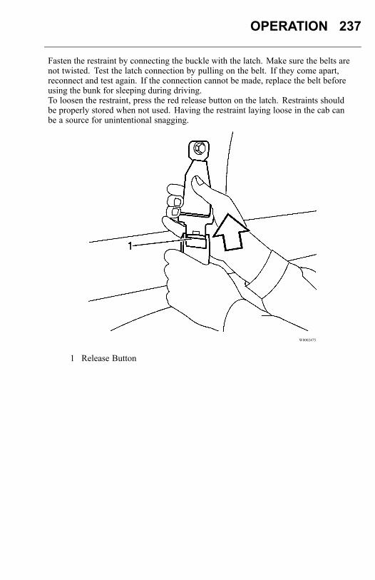
OPERATION 237
Fasten the restraint by connecting the buckle with the latch. Make sure the belts arenot twisted. Test the latch connection by pulling on the belt. If they come apart,reconnect and test again. If the connection cannot be made, replace the belt beforeusing the bunk for sleeping during driving.To loosen the restraint, press the red release button on the latch. Restraints shouldbe properly stored when not used. Having the restraint laying loose in the cab canbe a source for unintentional snagging.
W8002475
1 Release Button
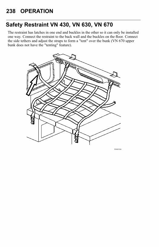
238 OPERATION
Safety Restraint VN 430, VN 630, VN 670The restraint has latches in one end and buckles in the other so it can only be installedone way. Connect the restraint to the back wall and the buckles on the floor. Connectthe side tethers and adjust the straps to form a "tent" over the bunk (VN 670 upperbunk does not have the "tenting" feature).
W8003206
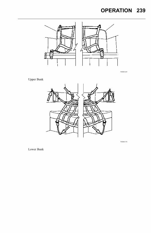
OPERATION 239
W8003169
Upper Bunk
W8003170
Lower Bunk
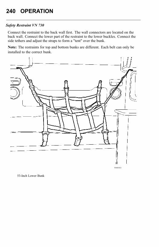
240 OPERATION
Safety Restraint VN 730
Connect the restraint to the back wall first. The wall connectors are located on theback wall. Connect the lower part of the restraint to the lower buckles. Connect theside tethers and adjust the straps to form a "tent" over the bunk.
Note: The restraints for top and bottom bunks are different. Each belt can only beinstalled to the correct bunk.
W8003822
53-Inch Lower Bunk
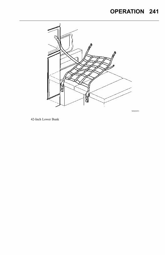
OPERATION 241
W8028593
42-Inch Lower Bunk
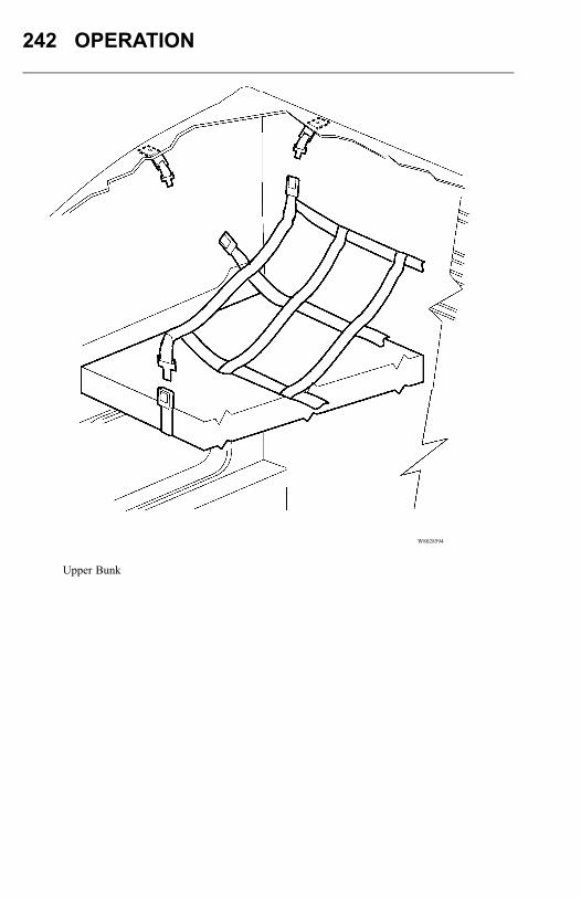
242 OPERATION
W8028594
Upper Bunk

OPERATION 243
Safety Restraint VN 780
Connect the restraint to the back wall first. The wall connectors are located in thestorage units. Connect the lower part of the restraint to the lower buckles. Connect theside tethers and adjust the straps to form a "tent" over the bunk.
Note: The restraints for top and bottom bunks are different. Each belt can only beinstalled to the correct bunk.
W8003217
Lower Bunk
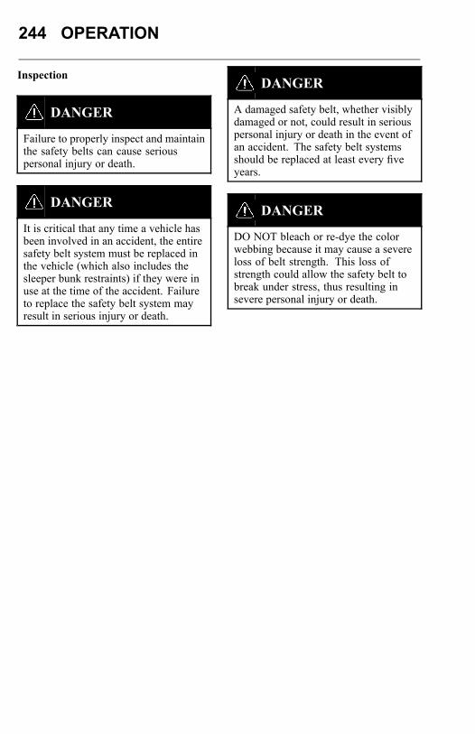
244 OPERATION
Inspection
DANGER
Failure to properly inspect and maintainthe safety belts can cause seriouspersonal injury or death.
DANGER
It is critical that any time a vehicle hasbeen involved in an accident, the entiresafety belt system must be replaced inthe vehicle (which also includes thesleeper bunk restraints) if they were inuse at the time of the accident. Failureto replace the safety belt system mayresult in serious injury or death.
DANGER
A damaged safety belt, whether visiblydamaged or not, could result in seriouspersonal injury or death in the event ofan accident. The safety belt systemsshould be replaced at least every fiveyears.
DANGER
DO NOT bleach or re-dye the colorwebbing because it may cause a severeloss of belt strength. This loss ofstrength could allow the safety belt tobreak under stress, thus resulting insevere personal injury or death.
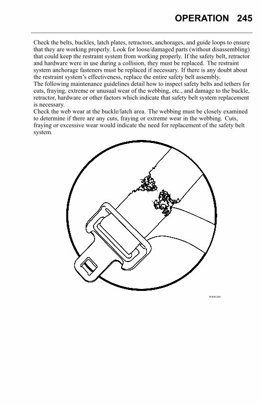
OPERATION 245
Check the belts, buckles, latch plates, retractors, anchorages, and guide loops to ensurethat they are working properly. Look for loose/damaged parts (without disassembling)that could keep the restraint system from working properly. If the safety belt, retractorand hardware were in use during a collision, they must be replaced. The restraintsystem anchorage fasteners must be replaced if necessary. If there is any doubt aboutthe restraint system’s effectiveness, replace the entire safety belt assembly.The following maintenance guidelines detail how to inspect safety belts and tethers forcuts, fraying, extreme or unusual wear of the webbing, etc., and damage to the buckle,retractor, hardware or other factors which indicate that safety belt system replacementis necessary.Check the web wear at the buckle/latch area. The webbing must be closely examinedto determine if there are any cuts, fraying or extreme wear in the webbing. Cuts,fraying or excessive wear would indicate the need for replacement of the safety beltsystem.
W8001406
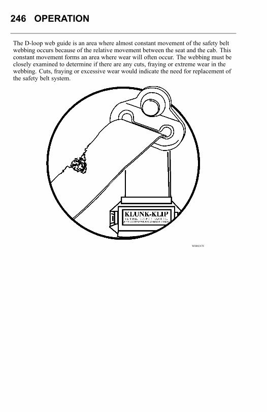
246 OPERATION
The D-loop web guide is an area where almost constant movement of the safety beltwebbing occurs because of the relative movement between the seat and the cab. Thisconstant movement forms an area where wear will often occur. The webbing must beclosely examined to determine if there are any cuts, fraying or extreme wear in thewebbing. Cuts, fraying or excessive wear would indicate the need for replacement ofthe safety belt system.
W8002478
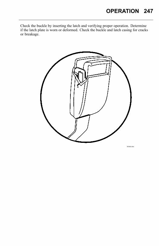
OPERATION 247
Check the buckle by inserting the latch and verifying proper operation. Determineif the latch plate is worn or deformed. Check the buckle and latch casing for cracksor breakage.
W8001404
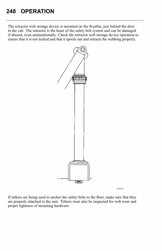
248 OPERATION
The retractor web storage device is mounted on the B-pillar, just behind the doorin the cab. The retractor is the heart of the safety belt system and can be damagedif abused, even unintentionally. Check the retractor web storage device operation toensure that it is not locked and that it spools out and retracts the webbing properly.
W8002481
If tethers are being used to anchor the safety belts to the floor, make sure that theyare properly attached to the seat. Tethers must also be inspected for web wear andproper tightness of mounting hardware.
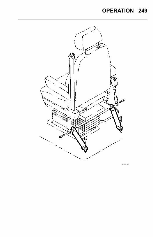
OPERATION 249
W8001387
250 OPERATION
All hardware for safety belt mounting points should be evaluated for corrosion. Allattachment points of the system should be checked for tightness of mounting hardware.Check the web in areas exposed to ultraviolet rays from the sun or extreme dust ordirt. If the original color of the web in these areas is extremely faded, the physicalstrength of this web may have deteriorated. If this condition exists, replace the safetybelt system.Important Facts About Safety Belts in Heavy TrucksThe high mileage associated with heavy trucks, the continual relative movement ofthe seat with the cab, the possible contact with the vehicle seat or other parts of thecab structure, and the potential exposure of this safety belt to severe environmentalconditions make it crucial to inspect the seat belt system regularly. It is recommendedthat the system is inspected every 24,000 km (15,000 miles) or more often if thevehicle is exposed to severe environmental or vocational conditions. Any safety beltsystem that shows cuts, fraying, extreme or unusual wear, significant discolorationsdue to ultraviolet ray exposure, dusty-dirty conditions, abrasion to the safety beltwebbing or damage to the buckle, latch plate, retractor, hardware or any other obviousproblem should be replaced immediately, regardless of the mileage.Once replacement of the safety belt has been determined necessary, be certain that it isreplaced only with a Volvo original replacement safety belt. See your authorized VolvoTruck dealer for replacement. Your Volvo safety belt system has been developed andtested specifically for heavy trucks. Replace it only with the exact same design thatthe vehicle was equipped with.If the inspection indicates that any other part of the safety belt system requiresreplacement, the entire belt system must be replaced. An installation guide is attachedto every replacement system, entitled "Three-Point Safety Belt Installation Guide."There are separate safety belt instruction guides for suspension and stationary seats.Use the proper guide for your type of seat and follow the instructions very closely. Itis vitally important that all components are mounted back in the same positions as theoriginal components that were removed. This will maintain the design integrity of themounting points for the safety belt assembly.
OPERATION 251
SEATS, GENERALSeveral seats can be used in the vehicles. If the seat installed in the vehicle is notexplained in this section, see your authorized Volvo dealer.Before adjusting or fastening the seat belt, move the seat forward or rearward andadjust the seat height as necessary. Sit erect and adjust the seat cushion and seat backto obtain a comfortable driving position.
DANGER
All adjustments are to be made whilethe operator is seated and the vehicleis stationary. DO NOT adjust the seatposition while driving the vehicle.Failure to follow this warning can resultin loss of vehicle control, which canresult in serious personal injury or deathin the event of a vehicle accident.
Driver Seats Passenger Seats
• NationalStandard Seat
• NationalComfort Seat
• BostromStandard Seat
• BostromComfort Seat
• NationalStandard Seat
• NationalComfort Seat
• NationalToolbox Seat
• BostromStandard Seat
• BostromComfort Seat
• BostromToolbox Seat
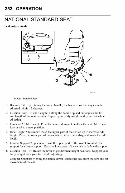
252 OPERATION
NATIONAL STANDARD SEATSeat Adjustments
W8002745
National Standard Seat
1 Backrest Tilt: By rotating the round handle, the backrest recline angle can beadjusted within 12 degrees.
2 Cushion Front Tilt and Length: Pulling the handle up and out adjusts the tiltand length of the seat cushion. Support your body weight with your feet whileadjusting.
3 Fore and Aft Movement: Press the lever sideways to unlock the seat. Move seatfore or aft to a new position.
4 Ride Height Adjustment: Push the upper part of the switch up to increase rideheight. Push the lower part of the switch to deflate the airbag and lower the rideheight.
5 Lumbar Support Adjustment: Push the upper part of the switch to inflate thesupport for a firmer support. Push the lower part of the switch to deflate the support.
6 Cushion Rear Tilt: Rotate the lever to get different height positions. Support yourbody weight with your feet while adjusting.
7 Chugger Snubber: Moving the handle down isolates the seat from the fore and aftmovement of the cab.
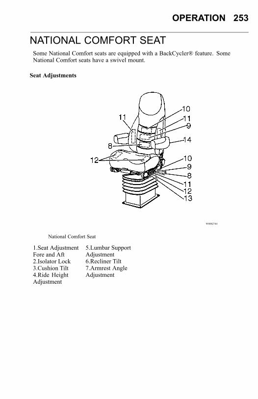
OPERATION 253
NATIONAL COMFORT SEATSome National Comfort seats are equipped with a BackCycler® feature. SomeNational Comfort seats have a swivel mount.
Seat Adjustments
W8002744
National Comfort Seat
1.Seat AdjustmentFore and Aft2.Isolator Lock3.Cushion Tilt4.Ride HeightAdjustment
5.Lumbar SupportAdjustment6.Recliner Tilt7.Armrest AngleAdjustment
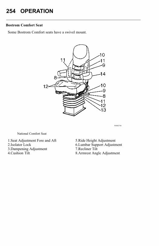
254 OPERATION
Bostrom Comfort Seat
Some Bostrom Comfort seats have a swivel mount.
W8002744
National Comfort Seat
1.Seat Adjustment Fore and Aft2.Isolator Lock3.Dampening Adjustment4.Cushion Tilt
5.Ride Height Adjustment6.Lumbar Support Adjustment7.Recliner Tilt8.Armrest Angle Adjustment
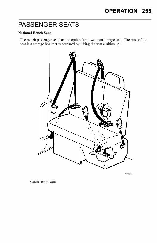
OPERATION 255
PASSENGER SEATSNational Bench Seat
The bench passenger seat has the option for a two-man storage seat. The base of theseat is a storage box that is accessed by lifting the seat cushion up.
W8003482
National Bench Seat
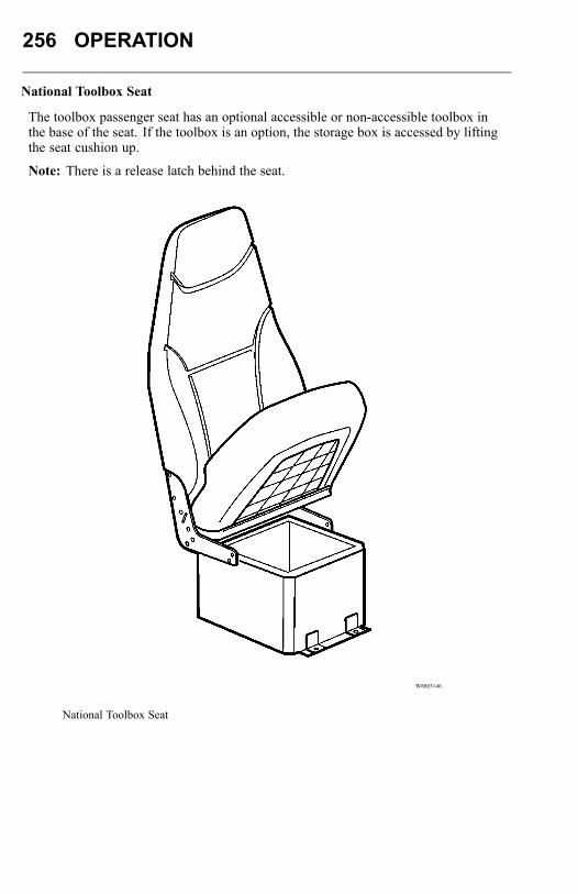
256 OPERATION
National Toolbox Seat
The toolbox passenger seat has an optional accessible or non-accessible toolbox inthe base of the seat. If the toolbox is an option, the storage box is accessed by liftingthe seat cushion up.
Note: There is a release latch behind the seat.
W8003146
National Toolbox Seat
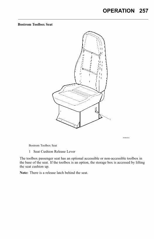
OPERATION 257
Bostrom Toolbox Seat
W8003851
Bostrom Toolbox Seat
1 Seat Cushion Release Lever
The toolbox passenger seat has an optional accessible or non-accessible toolbox inthe base of the seat. If the toolbox is an option, the storage box is accessed by liftingthe seat cushion up.
Note: There is a release latch behind the seat.
258 OPERATION
No Passenger Seat (Optional)WARNING
Using a temporary passenger seatingwithout the benefit of proper seatmounting and safety belt can, in theevent of a loss of control of the vehicle,cause serious personal injury or death.
In vehicles with no passenger seat installed, DO NOT let a passenger ride ontemporary seating. This is against the law and can be very dangerous.
OPERATION 259
ENGINE OPERATIONGeneral
Proper operation, driving techniques and maintenance are key factors in obtaining themaximum life and economy from a modern turbocharged diesel engine. This sectionhas operational information about the components that make up the engine.When changing gears, avoid lugging to extend engine life. When the engine isoperating at full throttle and maximum governed speed cannot be reached ormaintained, the engine is lugging. When approaching a hill requiring more power,it is necessary to downshift the transmission as the vehicle goes into the grade.Accelerating to the governed engine speed will give additional power at approximatelythe same road speed. For shifting instructions, see the transmission manufacturer’soperator’s manual.Always start moving the load in a gear low enough so that the engine can beaccelerated to the governed speed. Then shift to the next gear as the enginedecelerates. For loaded vehicles, do not skip a gear or lug the engine while getting upto cruising speed. For empty or light loads, it is permissible to skip gears.When operating on a level highway or at cruising speed, hold the engine speed atapproximately 1400 to 1600 rpm for large displacement engines to achieve power andeconomical fuel consumption.The operator should understand the operating characteristics of the engine the vehicleis equipped with. Modern diesel engines have maximum torques at much lowerengine speeds than in the past. As such, these engines are designed to performsatisfactorily at a lower speed. New transmissions with wide ratio steps betweengears demand the use of these engines.

260 OPERATION
This vehicle is equipped with an exhaust aftertreatment system which virtuallyeliminates exhaust smoke. Exhaust vapor may be visible during a cold start. Ifexhaust smoke is visible during engine operation, this indicates a problem with theexhaust aftertreatment system. Take the vehicle to an authorized Volvo Truck dealerimmediately.
IMMOBILIZER FEATUREVolvo Engines Only
The Immobilizer Feature is used to prevent the engine from starting. If your vehiclewas not ordered with this feature, it may be available from your dealer as an optionusing VCADS Pro.To secure the vehicle, the driver needs to enter the correct 3-digit code (PIN code) intothe Driver Information Display (DID) via the stalk switch.
W3006348
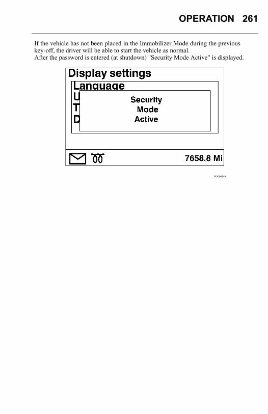
OPERATION 261
If the vehicle has not been placed in the Immobilizer Mode during the previouskey-off, the driver will be able to start the vehicle as normal.After the password is entered (at shutdown) "Security Mode Active" is displayed.
W3006349
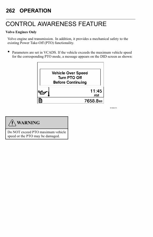
262 OPERATION
CONTROL AWARENESS FEATUREVolvo Engines Only
Volvo engine and transmission. In addition, it provides a mechanical safety to theexisting Power Take-Off (PTO) functionality.
• Parameters are set in VCADS. If the vehicle exceeds the maximum vehicle speedfor the corresponding PTO mode, a message appears on the DID screen as shown:
W3006376
WARNING
Do NOT exceed PTO maximum vehiclespeed or the PTO may be damaged.
OPERATION 263
FUEL ECONOMY DRIVINGGeneral
The absolute fuel consumption (counted in liters per 100 kilometers or miles per USgallon) is determined by a large number of circumstances which can be related to oneof the following main areas:
• Build specification and equipment• Service and maintenance• External environment• Driving habits
Due to these factors, fuel consumption can vary considerably within what is called"normal fuel consumption." Fuel consumption can vary from over 24 L/100 km (10mpg) when driving empty on a nice and dry summer road to 67 L/100 km (3.5 mpg)while driving with maximum permitted GVW, with vehicle and trailer, on a hillyand slushy winter road.
Build Specification and Equipment
Whenever a vehicle is used for transportation, its build specification, equipment andgross vehicle weight have a decisive effect on both fuel consumption and performance.The factors which have the greatest influence on fuel consumption are primarily:driveline combination, height of trailer or superstructure, use of air fairings, tire type,number of wheels, gross vehicle weight, and accessories.
Driveline Combination
Engine, transmission and final drive must be selected in such a way that the enginecan operate within the economic speed range at normal driving speed. This range isdefined as where the engine makes the best use of the energy content of the diesel fuel.A poorly selected rear axle ratio, which results in the engine speed being constantlyabove the optimum speed, will increase fuel consumption.
264 OPERATION
Tires
Heavy duty threaded tires increase rolling resistance considerably. For long haul,choose a smoother, ribbed type tire. Choose a lugged type tire only when the addedtraction in mud and snow is needed.The number of wheels (axles) has a direct effect on the rolling resistance and, thereby,the fuel consumption. For volume and/or low weight transports, the use of a 4x2instead of a 6x4 should be considered.If the tire pressure is too low, the rolling resistance increases and, thereby, increasesthe fuel consumption. The overall economy is also affected as tire wear increasesconsiderably.Gross Vehicle WeightThe gross vehicle weight of a vehicle combination has a large impact on the rollingresistance.AccessoriesAs a rule, accessories such as roof rack, advertising signs, bug screens, exposed airhorns, etc., have a negative effect on fuel consumption.Service and MaintenanceA modern heavy-duty vehicle requires regular and preventive maintenance to ensurethat all its components function as they should. Use the recommended preventivemaintenance (PM) program that Volvo Trucks North America has developed forthe vehicles. This ensures optimal energy efficiency from all components that areimportant to fuel consumption.

OPERATION 265
BrakesDragging brakes increase fuel consumption. They should be checked regularly. It isimportant that the release action of the air valves is fast and that the moving parts ofthe wheel brakes are checked for good adjustment and operation.AxlesAn axle out of alignment increases rolling resistance. Regularly check the front wheelalignment and axles on both the tractor and trailer/semi-trailer. If they are correct,there will be less rolling resistance and, therefore, lower fuel consumption.A good sign of an axle or wheel out of alignment is uneven tire wear. Check the tiresoften.EngineFaulty or incorrectly adjusted engine components increase fuel consumption. The listbelow gives some typical components that can influence fuel consumption:
• Blocked (on the outside) charge air cooler/radiator package• Faulty thermostat• Blocked fuel filters• Blocked air intake filter• Faulty injectors• Dirty turbocharger• Air in fuel system• Faulty fuel supply pump• Faulty fuel relief valve• Faulty fan thermostat/clutch
266 OPERATION
External EnvironmentUnder unfavorable conditions, the external environment can have a negative effect onfuel consumption. This can be broken down into two main groups: weather and wind,and the nature of the roads. Rain, snow, icy conditions and headwinds have a largenegative impact on fuel economy, as do hilly roads and uneven road surfaces.HeadwindsHeadwinds have a large negative impact on fuel consumption. With tailwinds, fuelsaving is only marginal.A good sign of an axle or wheel out of alignment is uneven tire wear. Check the tiresoften.Air TemperatureLow ambient temperature contributes to increased fuel consumption.Rain, Snow and Road SurfaceA wet road surface increases rolling resistance and, thereby, fuel consumption. Slushwill increase consumption even more. In certain cases, the surface structure of theroad can also have a negative effect on fuel consumption.GradientsA hilly road with many bends demands a higher output from the engine. Thedifference between flat, straight roads and hilly, winding roads can amount to as muchas a 50 percent increase in fuel consumption.When choosing your route, avoid hills, rough roads and frequent stops.
OPERATION 267
Driving HabitsThe way in which a vehicle is being driven is the one factor which has the greatestinfluence on fuel consumption. Correct driving saves fuel and reduces vehicle wear.To achieve optimal running economy, the driver should always remember to:
• Start the engine correctly (especially important in winter season).• Maintain an even and correct speed.• Keep the engine at its optimum speed range.• Use the correct uphill and downhill driving technique.
Starting the EngineStart the engine according to the instructions in the operator’s manual of the enginemanufacturer (for a Volvo engine, see "STARTING THE ENGINE" “STARTINGTHE ENGINE”, page 298). A proper start, especially during the cold season, savesfuel and reduces engine wear.Sluggish lube oil in the engine makes cold starting more difficult. Therefore, it isimportant to always use engine oil with the correct viscosity. (For the sake of theoverall fuel economy, it is also important to have the right viscosity of transmissionand rear axle oils.)A good sign of an axle or wheel out of alignment is uneven tire wear. Check the tiresoften.Avoid High Engine SpeedsHigh engine speeds mean high fuel consumption. "Jerky" driving also increases fuelconsumption when the vehicle is constantly accelerated and slowed down. Avoid ahigher consumption by steady, even driving.Refer to each engine manufacturer’s operator’s manual for information on the engine’soptimum operating range.Rain, Snow and Road SurfaceA wet road surface increases rolling resistance and, thereby, fuel consumption. Slushwill increase consumption even more. In certain cases, the surface structure of theroad can also have a negative effect on fuel consumption.Hill Driving TechniqueUse the inertia of the vehicle to go over the crest of a hill under reduced power. Usegravity to help with acceleration when going down the hill. Build up speed beforereaching the next uphill.
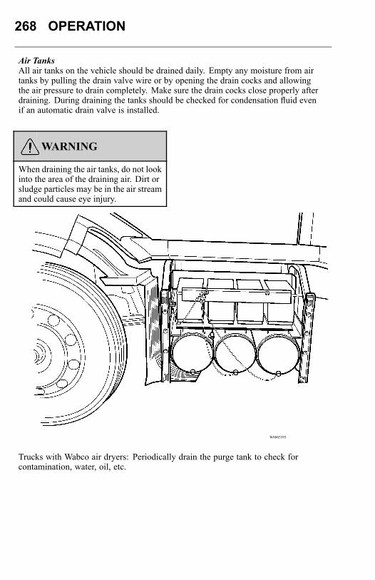
268 OPERATION
Air TanksAll air tanks on the vehicle should be drained daily. Empty any moisture from airtanks by pulling the drain valve wire or by opening the drain cocks and allowingthe air pressure to drain completely. Make sure the drain cocks close properly afterdraining. During draining the tanks should be checked for condensation fluid evenif an automatic drain valve is installed.
WARNING
When draining the air tanks, do not lookinto the area of the draining air. Dirt orsludge particles may be in the air streamand could cause eye injury.
W8003393
Trucks with Wabco air dryers: Periodically drain the purge tank to check forcontamination, water, oil, etc.
OPERATION 269
Trucks with automated Meritor Transmission: Drain the transmission air supply tanklocated on the right-hand rail daily to check for contamination, water, oil, etc.
Charging Air to Another Vehicle DANGER
Before working on a vehicle, set theparking brakes, place the transmissionin neutral, and block the wheels. Failureto do so can result in unexpected vehiclemovement and can cause seriouspersonal injury or death.
There are many methods which may be used to charge the air system of anothervehicle. Vehicles equipped with the standard two-valve system (trailer supply andparking brake) must use the following procedure when using the emergency trailer airline as an auxiliary air source, other than to charge the trailer air reservoirs.1 Connect the emergency trailer air line to the auxiliary source.2 Start the engine.
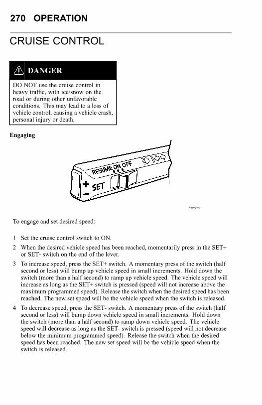
270 OPERATION
CRUISE CONTROL
DANGER
DO NOT use the cruise control inheavy traffic, with ice/snow on theroad or during other unfavorableconditions. This may lead to a loss ofvehicle control, causing a vehicle crash,personal injury or death.
Engaging
W3002499
To engage and set desired speed:
1 Set the cruise control switch to ON.2 When the desired vehicle speed has been reached, momentarily press in the SET+
or SET- switch on the end of the lever.3 To increase speed, press the SET+ switch. A momentary press of the switch (half
second or less) will bump up vehicle speed in small increments. Hold down theswitch (more than a half second) to ramp up vehicle speed. The vehicle speed willincrease as long as the SET+ switch is pressed (speed will not increase above themaximum programmed speed). Release the switch when the desired speed has beenreached. The new set speed will be the vehicle speed when the switch is released.
4 To decrease speed, press the SET- switch. A momentary press of the switch (halfsecond or less) will bump down vehicle speed in small increments. Hold downthe switch (more than a half second) to ramp down vehicle speed. The vehiclespeed will decrease as long as the SET- switch is pressed (speed will not decreasebelow the minimum programmed speed). Release the switch when the desiredspeed has been reached. The new set speed will be the vehicle speed when theswitch is released.
OPERATION 271
Note: The cruise control cannot be engaged at speeds below approximately 30 km/h(18 mph).DisengagingThe cruise control is disengaged if the brake is depressed, or if the cruise controlswitch is set to OFF. If the ignition key is turned back to the accessories position (I),the cruise control system will automatically be disengaged.If configured, the cruise control will remain engaged if the clutch pedal is depressedfor short durations (to allow shifting while in cruise control). However, if the clutchpedal is depressed for an extended period (typically greater than 5 seconds), cruisecontrol will be disengaged.Resuming Vehicle SpeedThe previously selected cruise speed is retained in the memory. When the cruisecontrol switch is pushed to the RESUME position, the vehicle resumes the previouslyset speed (provided vehicle speed exceeds approximately 15 km/h [10 mph] when theswitch is pressed and the speed is not above the maximum programmed speed).
272 OPERATION
Note: Read the Eaton VORAD Collision Warning System Driver Reference Manualbefore taking a vehicle equipped with VORAD out on the road.
CAUTION
On vehicles equipped with EatonVORAD SmartCruise, cruise control isdisengaged in the event the SmartCruisesystem fails to operate. You must stopthe truck, turn the ignition off and on,and activate the control twice in orderfor the cruise control to operate.
AccelerationMomentary acceleration (such as for passing another vehicle) does not interrupt cruisecontrol operation. After passing, release accelerator and let the vehicle slow to cruisecontrol speed. The previously set speed will then be maintained without having to setthe switch to RESUME.
Volvo Engine Brake (I-VEB)
The Volvo Engine Brake (I-VEB) is standard on the Volvo 16F engine and optional onthe 13F engine. It has a higher braking effect than the variable geometry turbo brake.When the engine brake is in the A position and cruise control is engaged, the enginebrake automatically engages if vehicle speed exceeds the set cruise control speed.The I-VEB will engage with infinite control (within the limits of the engine brake)to maintain that speed.
The Volvo Engine Brake (I-VEB) is standard on the Volvo 16F engine and optional onthe 13F engine. It has a higher braking effect than the variable geometry turbo brake.When the engine brake is in the A position and cruise control is engaged, the enginebrake automatically engages if vehicle speed exceeds the set cruise control speed.The I-VEB will engage with infinite control (within the limits of the engine brake)to maintain that speed.

OPERATION 273
BRAKE OPERATIONBrake Safety Information
DANGER
DO NOT inspect or adjust parts orcomponents in the brake system withoutsetting the parking brake, placing thetransmission in neutral and securelychocking the wheels. If the vehicle isnot secured to prevent uncontrolledvehicle movement, it could roll andcause severe personal injury or death.
DANGER
DO NOT use replacement partsanywhere in the brake system unlessit conforms exactly to originalspecifications. A nonconforming partin your vehicle’s brake system couldcause a malfunction, leading to loss ofcontrol of the vehicle resulting in severepersonal injury or death.
DANGER
DO NOT ride the brakes going downsteep hills. The brakes could overheatand lose their effectiveness. Alwayschoose a low gear before going downthe grade and reduce speed to helpcontrol vehicle speed. Losing thebrakes going downhill can lead to anaccident causing serious personal injuryor death.
274 OPERATION
DANGER
DONOT operate the vehicle when thereis a malfunction in the compressed airsystem. An air brake system with leaksor other malfunctions may prevent thebrake system from operating properly.The vehicle should not be operated untilthe system is repaired and all brakecircuits are working properly. Failureto repair the system can lead to loss ofcontrol of the vehicle resulting in severepersonal injury or death.
DANGER
The brake system is a critical vehiclesafety system. For your safety andfor those around you, follow therecommended preventive maintenancechecks. If any problems occur, havethem investigated immediately by anauthorized service facility. Failure toproperly maintain the brake system canresult in compromised brake efficiencyand may lead to loss of control of thevehicle resulting in severe personalinjury or death.
DANGER
DO NOT drive through deep water.The brake system can be affected so thebraking efficiency is less or the brakespull the vehicle to one side. This couldlead to an accident, personal injury ordeath.
OPERATION 275
DANGER
Automatic slack adjusters MUSTNOT be manually adjusted in aneffort to correct excessive push rodstroke, as this condition indicates thata problem exists with the automaticadjuster, installation of the automaticslack adjuster or problems related tocomponents of the foundation brakes.These conditions will not be correctedby manually adjusting the automaticslack adjusters.Manual adjustment of the automaticslack adjusters is a dangerouspractice that could result in seriousconsequences. This practice gives thevehicle operator a false sense of securityabout the effectiveness of the brakes,and the brakes will likely soon be out ofadjustment again.
General
All Volvo vehicles are designed to meet or exceed all applicable federal brakestandards and regulations. They use a dual circuit, compressed air system. It consistsof two independent brake systems that use a single set of brake controls. Each circuitis supplied by its own compressed air tank. Both air tanks receive compressed airfrom the same supply tank (wet tank) and are charged with equal pressure. The twocircuits are interconnected for the parking brake system.
DANGER
DO NOT release the parking brake orattempt to move the vehicle until brakeair pressure in both circuits is at least690 kPa (100 psi). Failure to followthis procedure may lead to uncontrolledvehicle movement and cause severepersonal injury or death.
276 OPERATION
DANGER
Never release or drive a truck that hasa brake discrepancy — no matter howminor — until it has been repairedor corrected. Failure to repair brakediscrepancies can result in compromisedbrake efficiency and may lead to loss ofcontrol of the vehicle resulting in severepersonal injury or death.
Air pressures in the two circuits are monitored by two pressure gauges on the rightside of the instrument cluster. The primary (rear) brake circuit gauge is marked withan "R" within a symbol and the secondary (front) brake circuit gauge is marked withan "F" within a symbol. The two pointers should register equal or nearly equalpressure. By observing the gauge pointers, the operator is forewarned in the event of apressure drop in either or both of the circuits.
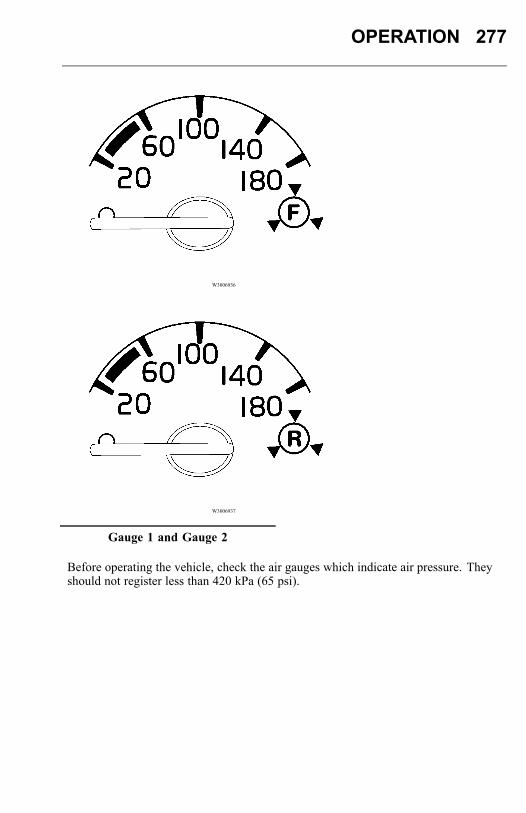
OPERATION 277
W3006936
W3006937
Gauge 1 and Gauge 2
Before operating the vehicle, check the air gauges which indicate air pressure. Theyshould not register less than 420 kPa (65 psi).
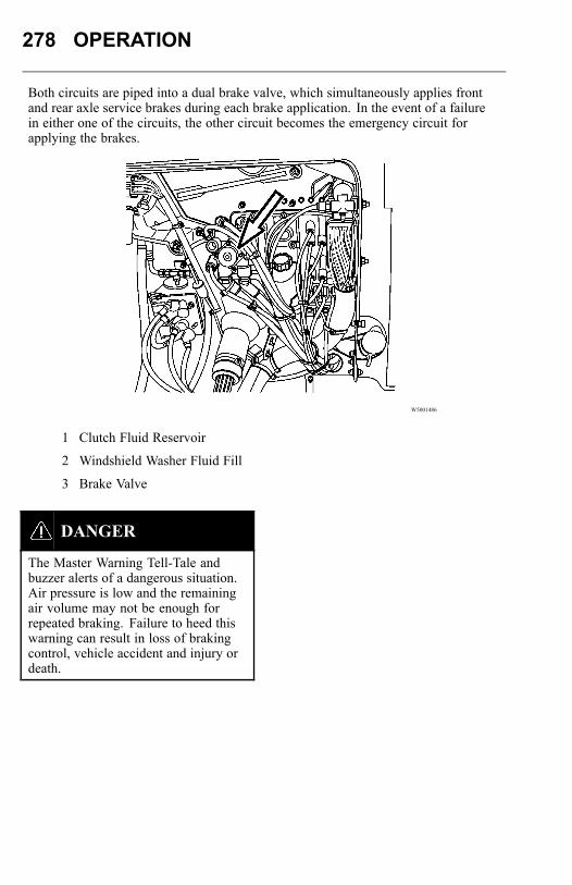
278 OPERATION
Both circuits are piped into a dual brake valve, which simultaneously applies frontand rear axle service brakes during each brake application. In the event of a failurein either one of the circuits, the other circuit becomes the emergency circuit forapplying the brakes.
W5001486
1 Clutch Fluid Reservoir
2 Windshield Washer Fluid Fill
3 Brake Valve
DANGER
The Master Warning Tell-Tale andbuzzer alerts of a dangerous situation.Air pressure is low and the remainingair volume may not be enough forrepeated braking. Failure to heed thiswarning can result in loss of brakingcontrol, vehicle accident and injury ordeath.
OPERATION 279
W3005171
Master Warning Tell-Tale
An important feature of the brake system is that an automatic spring brake applicationdoes not take place as a result of an air loss in only one of the two circuits. In thiscase, brake control remains in the foot brake valve. In each air pressure gauge, thereis a warning light connected to a low pressure switch that comes on if air pressuregoes below 420 kPa (60 psi). At the same time, the buzzer will sound and the mainwarning tell-tale will come on. This pressure drop warns the operator to make amanual emergency stop before an automatic emergency stop takes place.Brake System ControlsThe air compressor, governor, pressure regulator valve and reservoirs are controldevices. Their function is to build up, maintain and control air pressure in thereservoirs. This is so that pressure is held constant between the minimum andmaximum range established for air brake operation.The brake valve, quick release valve, brake chambers and slack adjusters areapplication devices. They distribute the air pressure and convert its energy into themechanical force necessary to apply or release the brakes.
280 OPERATION
Foot Brake ValveThe foot brake valve is directly connected to the brake pedal. The valve gives aprogressive output against the pedal travel. This allows better control of the pressurein the first half of the pedal travel. In the last half of the pedal travel, the pressureoutput increase is faster.The foot brake valve applies the service brakes, incorporating both the primaryand secondary air systems. The primary system controls the rear brakes and thesecondary system controls the front brakes. The foot brake valve receives air fromthe compressed air tanks. Air pressure is then delivered to the wheel brake chambersas required by the amount of pressure exerted on the foot brake pedal. The brakechamber force then applies the wheel brakes.From the operator’s viewpoint, operating the foot brake valve of a vehicle equippedwith air brakes differs very little from the operation of a conventionally brakedvehicle. Because the operation of the brake pedal requires scarcely more effort thandepressing the average throttle pedal, air brakes are naturally much easier to control.If the driver gives full attention to the following suggestions, a little experience willmake him/her thoroughly familiar with the air-controlled braking of this vehicle.
DANGER
Failure to observe these precautionscan result in loss of vehicle control andserious personal injury or death.
OPERATION 281
1 The best possible stop will be made when the first brake application is as firm asthe speed and road condition permit. Then, ease off as the speed is reduced. Neverapply the brakes lightly at first and increase the pressure as the speed diminishes.
2 DO NOT fan the brake pedal. Fanning gives poor brake performance and wastesair.
3 The air brake is designed so that when the brake pedal is fully depressed, anemergency application results. This application should be made only in anemergency situation.
4 In making a stop or a slow-down, allow the transmission to remain in gear with thethrottle closed, disengaging the clutch only when engine idling speed is reached.
5 When parking the vehicle, place the transmission in neutral and set the parkingbrake before shutting down the engine.
6 When descending a long grade, do not use the service brakes too long or too often.The brakes may overheat and lose their effectiveness.
7 Before descending a steep grade, the transmission should be shifted into a lowergear and the vehicle speed reduced. Other speed retarding devices should also beused if available (engine brakes, retarders or trailer hand control valves).
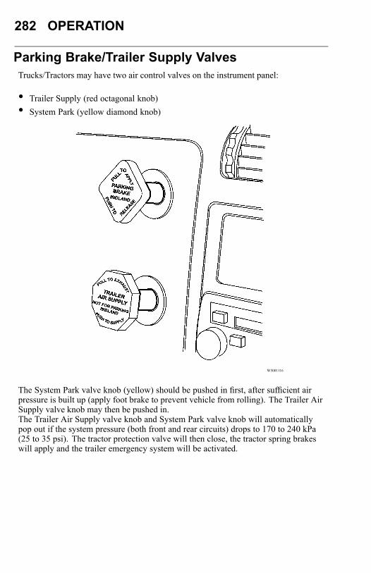
282 OPERATION
Parking Brake/Trailer Supply ValvesTrucks/Tractors may have two air control valves on the instrument panel:
• Trailer Supply (red octagonal knob)• System Park (yellow diamond knob)
W5001116
The System Park valve knob (yellow) should be pushed in first, after sufficient airpressure is built up (apply foot brake to prevent vehicle from rolling). The Trailer AirSupply valve knob may then be pushed in.The Trailer Air Supply valve knob and System Park valve knob will automaticallypop out if the system pressure (both front and rear circuits) drops to 170 to 240 kPa(25 to 35 psi). The tractor protection valve will then close, the tractor spring brakeswill apply and the trailer emergency system will be activated.
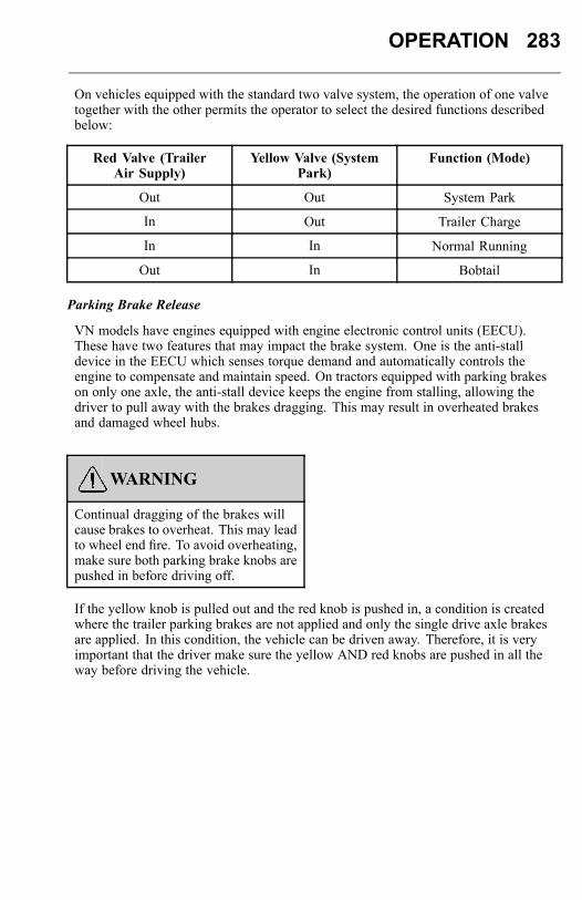
OPERATION 283
On vehicles equipped with the standard two valve system, the operation of one valvetogether with the other permits the operator to select the desired functions describedbelow:
Red Valve (TrailerAir Supply)
Yellow Valve (SystemPark)
Function (Mode)
Out Out System Park
In Out Trailer Charge
In In Normal Running
Out In Bobtail
Parking Brake Release
VN models have engines equipped with engine electronic control units (EECU).These have two features that may impact the brake system. One is the anti-stalldevice in the EECU which senses torque demand and automatically controls theengine to compensate and maintain speed. On tractors equipped with parking brakeson only one axle, the anti-stall device keeps the engine from stalling, allowing thedriver to pull away with the brakes dragging. This may result in overheated brakesand damaged wheel hubs.
WARNING
Continual dragging of the brakes willcause brakes to overheat. This may leadto wheel end fire. To avoid overheating,make sure both parking brake knobs arepushed in before driving off.
If the yellow knob is pulled out and the red knob is pushed in, a condition is createdwhere the trailer parking brakes are not applied and only the single drive axle brakesare applied. In this condition, the vehicle can be driven away. Therefore, it is veryimportant that the driver make sure the yellow AND red knobs are pushed in all theway before driving the vehicle.
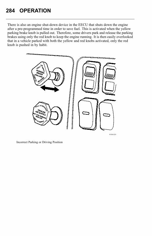
284 OPERATION
There is also an engine shut-down device in the EECU that shuts down the engineafter a pre-programmed time in order to save fuel. This is activated when the yellowparking brake knob is pulled out. Therefore, some drivers park and release the parkingbrakes using only the red knob to keep the engine running. It is then easily overlookedthat in a vehicle parked with both the yellow and red knobs activated, only the redknob is pushed in by habit.
W5001429
Incorrect Parking or Driving Position
OPERATION 285
Spring Brake for Parking
DANGER
Never leave the vehicle without beingcertain the parking brakes are set or thatother precautions are taken to preventthe vehicle from rolling. Failure to doso can result in serious personal injuryor death.
DANGER
Before working on or inspecting avehicle, set the parking brakes, placethe transmission in neutral and blockthe wheels. Failure to do so can result inunexpected vehicle movement and cancause serious personal injury or death.
The parking brake mechanism uses spring pressure as a separate power medium toapply the service brakes on the driving axles. The parking brake is released by thesame compressed air source used to apply the service brakes. Since this brake isreleased by air pressure, the system must be charged to at least 420 kPa (60 psi)before the parking brake may be released.
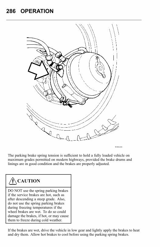
286 OPERATION
W5001430
The parking brake spring tension is sufficient to hold a fully loaded vehicle onmaximum grades permitted on modern highways, provided the brake drums andlinings are in good condition and the brakes are properly adjusted.
CAUTION
DO NOT use the spring parking brakesif the service brakes are hot, such asafter descending a steep grade. Also,do not use the spring parking brakesduring freezing temperatures if thewheel brakes are wet. To do so coulddamage the brakes, if hot, or may causethem to freeze during cold weather.
If the brakes are wet, drive the vehicle in low gear and lightly apply the brakes to heatand dry them. Allow hot brakes to cool before using the parking spring brakes.

OPERATION 287
There are several ways to determine if the parking brakes have been set. By pullingout the yellow knob:• An audible rush of air will be heard when the parking brake knob is pulled. The
air exhausts from the park brake valve itself and from the spring brake chamberson the rear axle(s).
• A black ring around the base of the yellow control knob will be seen.• The engine will stall if an attempt is made to set the vehicle in motion.• There will be a fluctuation in the air pressure gauge needles.• The knob cannot be pulled out any further.
DANGER
DO NOT attempt in any way todisassemble or tamper with the springbrake chamber. The force stored in thespring, if suddenly released, can causeserious personal injury or death.
DANGER
DO NOT apply the parking brake whilethe vehicle is moving. The rear wheelsmay lock up causing loss of vehiclecontrol leading to an accident, personalinjury or death.
288 OPERATION
Trailer Brake Hand Control
DANGER
The trailer hand brake control is not aparking brake valve and must not beused as one. This brake is not designedto hold the vehicle stationary. Failureto follow these instructions can resultin the unintentional movement of thevehicle and may cause personal injuryor death.
DANGER
DO NOT use the trailer brake handcontrol as a parking brake. The brakescould release and the vehicle could roll,causing a vehicle accident, personalinjury or death.
The hand control valve for the trailer brakes engages the trailer brakes independentlyfrom the vehicle brakes. The valve can be fully or partially engaged but in any partialposition it will be overridden by a full application of the foot brake valve.To supply air to the trailer brakes to slow the trailer down, pull the valve handle down.The farther the handle is pulled down, the more air pressure is applied to the trailerbrakes. Releasing the self-returning handle releases the trailer brakes.
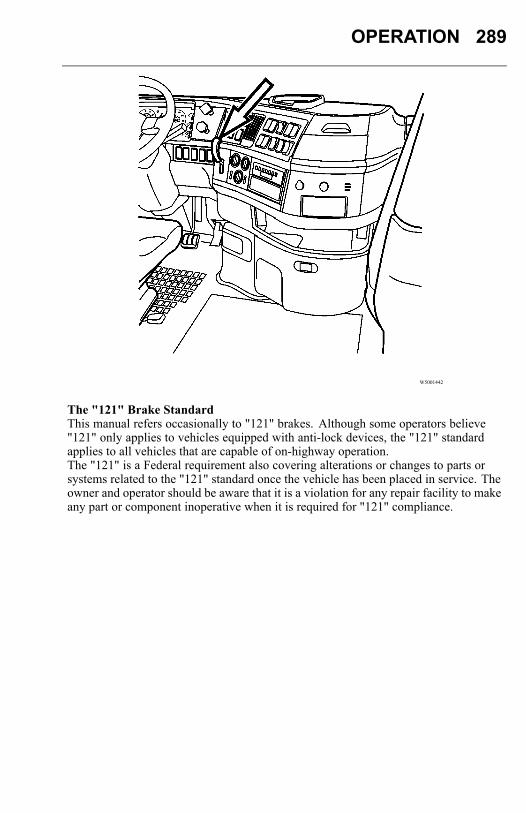
OPERATION 289
W5001442
The "121" Brake StandardThis manual refers occasionally to "121" brakes. Although some operators believe"121" only applies to vehicles equipped with anti-lock devices, the "121" standardapplies to all vehicles that are capable of on-highway operation.The "121" is a Federal requirement also covering alterations or changes to parts orsystems related to the "121" standard once the vehicle has been placed in service. Theowner and operator should be aware that it is a violation for any repair facility to makeany part or component inoperative when it is required for "121" compliance.
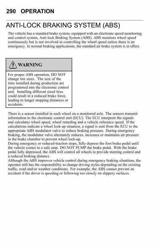
290 OPERATION
ANTI-LOCK BRAKING SYSTEM (ABS)The vehicle has a standard brake system, equipped with an electronic speed monitoringand control system, Anti-lock Braking System (ABS). ABS monitors wheel speedcontinuously but is not involved in controlling the wheel speed unless there is anemergency. In normal braking applications, the standard air brake system is in effect.
WARNING
For proper ABS operation, DO NOTchange tire sizes. The size of thetires installed during production areprogrammed into the electronic controlunit. Installing different sized tirescould result in a reduced brake force,leading to longer stopping distances oraccidents.
There is a sensor installed in each wheel on a monitored axle. The sensors transmitinformation to the electronic control unit (ECU). The ECU interprets the signalsand calculates wheel speed, wheel retarding and a vehicle reference speed. If thecalculations indicate a wheel lock-up situation, a signal is sent from the ECU to theappropriate ABS modulator valve to reduce braking pressure. During emergencybraking, the modulator valve alternately reduces, increases or maintains air pressurein the brake chamber to prevent wheel lock-up.During emergency or reduced-traction stops, fully depress the foot brake pedal untilthe vehicle comes to a safe stop. DO NOT PUMP the brake pedal. With the brakepedal fully depressed, the ABS will control all wheels to provide steering control anda reduced braking distance.Although the ABS improves vehicle control during emergency braking situations, theoperator still has the responsibility to change driving styles depending on the existingtraffic, road and/or weather conditions. For example, the ABS cannot prevent anaccident if the driver is speeding or following too closely on slippery surfaces.
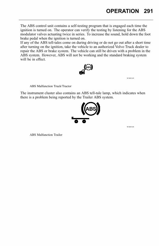
OPERATION 291
The ABS control unit contains a self-testing program that is engaged each time theignition is turned on. The operator can verify the testing by listening for the ABSmodulator valves actuating twice in series. To increase the sound, hold down the footbrake pedal when the ignition is turned on.If any of the ABS tell-tales come on during driving or do not go out after a short timeafter turning on the ignition, take the vehicle to an authorized Volvo Truck dealer torepair the ABS or brake system. The vehicle can still be driven with a problem in theABS system. However, ABS will not be working and the standard braking systemwill be in effect.
W3005149
ABS Malfunction Truck/Tractor
The instrument cluster also contains an ABS tell-tale lamp, which indicates whenthere is a problem being reported by the Trailer ABS system.
W3005148
ABS Malfunction Trailer
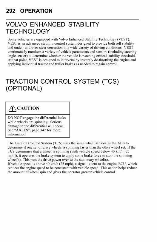
292 OPERATION
VOLVO ENHANCED STABILITYTECHNOLOGYSome vehicles are equipped with Volvo Enhanced Stability Technology (VEST).VEST is an advanced stability control system designed to provide both roll stabilityand under- and over-steer correction in a wide variety of driving conditions. VESTcontinuously monitors a variety of vehicle parameters and sensors (including steeringangle sensor) to determine whether the vehicle is reaching critical stability threshold.At that point, VEST is designed to intervene by instantly de-throttling the engine andapplying individual tractor and trailer brakes as needed to regain control.
TRACTION CONTROL SYSTEM (TCS)(OPTIONAL)
CAUTION
DO NOT engage the differential lockswhile wheels are spinning. Seriousdamage to the differential will occur.See “AXLES”, page 342 for moreinformation.
The Traction Control System (TCS) uses the same wheel sensors as the ABS todetermine if one set of drive wheels is spinning faster than the other wheel set. If theTCS determines that a wheel is spinning (with vehicle speed below 40 km/h [25mph]), it operates the brake system to apply some brake force to stop the spinningwheel(s). This puts the drive power over to the stationary wheel(s).If vehicle speed is above 40 km/h (25 mph), a signal is sent to the engine ECU, whichreduces the engine speed to be consistent with vehicle speed. This action helps reducethe amount of wheel spin and gives the operator greater vehicle control.
OPERATION 293
W3000962
The TCS includes a switch to turn off the function. When the switch is in the OFFposition, the TCS operates normally to increase traction if the drive wheels beginspinning. When the switch is pressed once, the TCS tell-tale in the instrument clusterblinks continuously, indicating that the TCS is in mud/snow mode.
W3001336
The mud/snow mode increases available traction on soft surfaces like snow, slush ormud by slightly increasing the allowable wheel spin. This prevents the wheels fromgetting bogged down. The TCS will resume normal operation when the TCS switch ispressed again and the TCS tell-tale goes out or when the ignition is turned off.

294 OPERATION
Tire Pressure System (If Equipped)The tire pressure/temperature sensor is attached to each wheel with a stainless steeltire strap and is located in line with the wheels valve stem. This self powered sensor isresponsible for transmitting the tire cavity pressure and temperature to the system viaa radio frequency sign that is received by the system antenna.
1. Tire Pressure
W3035597
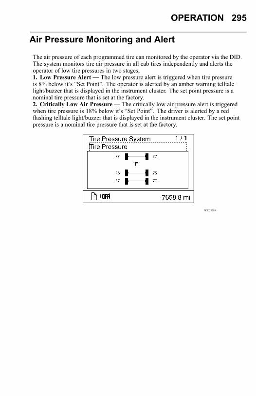
OPERATION 295
Air Pressure Monitoring and Alert
The air pressure of each programmed tire can monitored by the operator via the DID.The system monitors tire air pressure in all cab tires independently and alerts theoperator of low tire pressures in two stages;1. Low Pressure Alert — The low pressure alert is triggered when tire pressureis 8% below it’s “Set Point”. The operator is alerted by an amber warning telltalelight/buzzer that is displayed in the instrument cluster. The set point pressure is anominal tire pressure that is set at the factory.2. Critically Low Air Pressure — The critically low air pressure alert is triggeredwhen tire pressure is 18% below it’s “Set Point”. The driver is alerted by a redflashing telltale light/buzzer that is displayed in the instrument cluster. The set pointpressure is a nominal tire pressure that is set at the factory.
W3035599
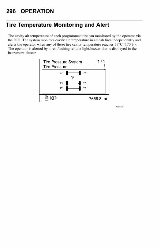
296 OPERATION
Tire Temperature Monitoring and Alert
The cavity air temperature of each programmed tire can monitored by the operator viathe DID. The system monitors cavity air temperature in all cab tires independently andalerts the operator when any of these tire cavity temperature reaches 77°C (170°F).The operator is alerted by a red flashing telltale light/buzzer that is displayed in theinstrument cluster.
W3035599
OPERATION 297
VEHICLE SPEED RETARDING DEVICES
DANGER
When operating a tractor bobtail(without a trailer) or on slippery roads,the engine brake switch must be in the"OFF" position. Failure to follow thisinstruction can result in loss of vehiclecontrol and serious personal injury ordeath.
Note: The vehicle ABS will automatically turn off the vehicle speed retardingdevice, IF one of the sensed rear wheels is locking up as a result of vehicle speedretarding device operation. The vehicle speed retarding device will be turned backon automatically when the wheels become unlocked. Consider switching to a lowerbraking level if this occurs frequently.A vehicle speed retarding device is not intended to bring the vehicle to a stop. Avehicle speed retarding device is only intended to retard the vehicle speed undercertain conditions.
Note: It is normal for there to be a slight delay in the application of a vehicle speedretarding device. When using devices of this type, be sure to think ahead and analyzeconditions in order to use the device properly.
Volvo Variable Geometry Turbo Brake
The variable geometry turbo brake is standard with the Volvo 11F and 13F engine. Ituses software to close the variable geometry turbocharger to create retardation.
Note: For both variable geometry turbocharger and engine brakes, use a "one gear"driving strategy when going downhill to keep engine speed up for effective braking(for example: uphill in 7th gear and downhill in 6th).
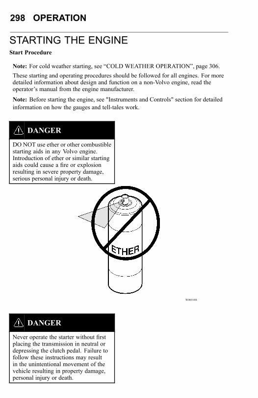
298 OPERATION
STARTING THE ENGINEStart Procedure
Note: For cold weather starting, see “COLD WEATHER OPERATION”, page 306.These starting and operating procedures should be followed for all engines. For moredetailed information about design and function on a non-Volvo engine, read theoperator’s manual from the engine manufacturer.
Note: Before starting the engine, see "Instruments and Controls" section for detailedinformation on how the gauges and tell-tales work.
DANGER
DO NOT use ether or other combustiblestarting aids in any Volvo engine.Introduction of ether or similar startingaids could cause a fire or explosionresulting in severe property damage,serious personal injury or death.
W0001484
DANGER
Never operate the starter without firstplacing the transmission in neutral ordepressing the clutch pedal. Failure tofollow these instructions may resultin the unintentional movement of thevehicle resulting in property damage,personal injury or death.
OPERATION 299
1. Before starting the engine, perform the engine pre-trip inspection anddaily maintenance checks in on “PRE-TRIP INSPECTION AND DAILYMAINTENANCE”, page 192.
2. Make sure the parking brakes are engaged.
3. Place the transmission in neutral or depress the clutch pedal.
CAUTION
DO NOT crank the engine for morethan 30 seconds at a time; wait twominutes after each try to allow thestarter to cool. Failure to follow theseinstructions could cause starter damage.
Note: Some starters are equipped with starter protection. If the engine is running, thestarter temperature is too high, the transmission is not in neutral or the clutch pedal isnot depressed, starter engagement is inhibited. Also, when the key is turned to thestart position, there is a one second delay before the starter is engaged.
Note: The starter will not operator if the PTO is engaged.
4. Turn on the ignition with the switch key. Some tell-tales will come on in a routinecheck that shows the bulbs and systems are OK If any of the tell-tales stay lit, thatfunction of the vehicle may not be operable. DO NOT operate the vehicle untilthe problem is repaired. For an explanation of the tell-tales, Refer to the DriverInformation Display Manual.
5. Turn the key to the start position. Release key as soon as the engine has started. Forthe Volvo engine, the preheater can be engaged to help starting in cold temperatures.
CAUTION
If at start-up, or thereafter, the oilpressure gauge indicates any drop in oilpressure, the engine must be shut downimmediately. Failure to stop the enginemay cause major engine damage.
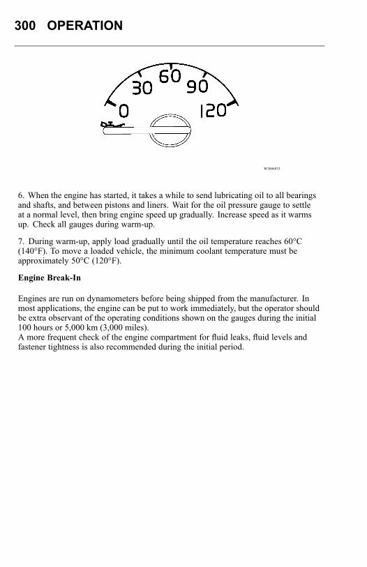
300 OPERATION
W3006933
6. When the engine has started, it takes a while to send lubricating oil to all bearingsand shafts, and between pistons and liners. Wait for the oil pressure gauge to settleat a normal level, then bring engine speed up gradually. Increase speed as it warmsup. Check all gauges during warm-up.
7. During warm-up, apply load gradually until the oil temperature reaches 60°C(140°F). To move a loaded vehicle, the minimum coolant temperature must beapproximately 50°C (120°F).
Engine Break-In
Engines are run on dynamometers before being shipped from the manufacturer. Inmost applications, the engine can be put to work immediately, but the operator shouldbe extra observant of the operating conditions shown on the gauges during the initial100 hours or 5,000 km (3,000 miles).A more frequent check of the engine compartment for fluid leaks, fluid levels andfastener tightness is also recommended during the initial period.
OPERATION 301
Engine Overspeed
This vehicle is equipped with a diesel engine and should not be operated in an areawith a concentration of hydrocarbon vapors (for example gasoline or diesel fuelfumes). Be especially cautious of low-lying or closed-in areas. The vapors may bedrawn into the engine through the air intake and cause the engine to overspeed. Hotcarbon and other sparks may come from the exhaust system, and cause an explosionand fire.If the vehicle is in an area where hydrocarbon vapors may be present, shut the engineoff immediately if any abnormalities are experienced. DO NOT leave it unattended.
DANGER
The diesel engine will operate on anyfuel which enters the cylinder, whetherit is from the injectors or from the airintake system. Therefore, if any solventis used to flush out the air cleanerelement, the engine may overspeedduring start-up. Engine damage andsevere injury and/or death from burnsor explosion can occur.
Idling
Diesel engines are electronically governed. The idle speed is pre-programmed fromthe manufacturer. Low idle speed is adjustable within certain limits (for most enginesbetween 600 to 750 rpm).The common belief that idling a diesel engine causes no engine damage is wrong.Idling produces sulfuric acid, which breaks down the oil and eats into bearings, rings,valve stems and engine surfaces.
Note: Avoid excessive idling. If the vehicle is parked for more than 5 minutes, stopthe engine. An engine can burn from 3 to 5.5 liters (0.75 to 1.5 gallons) of fuel perhour while idling. During long engine idling periods, the engine coolant temperaturemay fall below the normal operating range. Incomplete combustion of fuel during thewarm-up period can cause dilution of the oil in the crankcase, formation of lacquer orgummy deposits on the valves, pistons and rings, and rapid accumulation of sludgein the engine.
Low Idle Adjustment DANGER
Before setting the idle, apply the parkingbrakes and place the transmission inneutral. Failure to do so can result inunexpected vehicle movement and cancause serious personal injury or death.
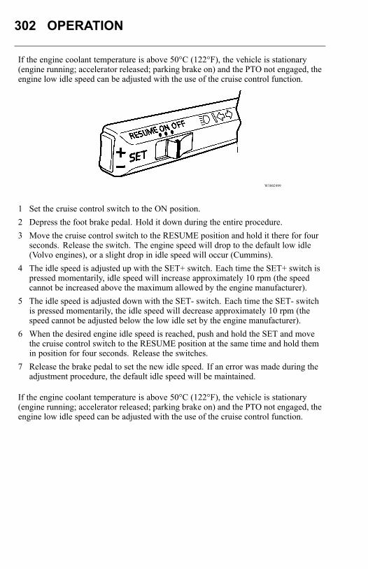
302 OPERATION
If the engine coolant temperature is above 50°C (122°F), the vehicle is stationary(engine running; accelerator released; parking brake on) and the PTO not engaged, theengine low idle speed can be adjusted with the use of the cruise control function.
W3002499
1 Set the cruise control switch to the ON position.2 Depress the foot brake pedal. Hold it down during the entire procedure.3 Move the cruise control switch to the RESUME position and hold it there for four
seconds. Release the switch. The engine speed will drop to the default low idle(Volvo engines), or a slight drop in idle speed will occur (Cummins).
4 The idle speed is adjusted up with the SET+ switch. Each time the SET+ switch ispressed momentarily, idle speed will increase approximately 10 rpm (the speedcannot be increased above the maximum allowed by the engine manufacturer).
5 The idle speed is adjusted down with the SET- switch. Each time the SET- switchis pressed momentarily, the idle speed will decrease approximately 10 rpm (thespeed cannot be adjusted below the low idle set by the engine manufacturer).
6 When the desired engine idle speed is reached, push and hold the SET and movethe cruise control switch to the RESUME position at the same time and hold themin position for four seconds. Release the switches.
7 Release the brake pedal to set the new idle speed. If an error was made during theadjustment procedure, the default idle speed will be maintained.
If the engine coolant temperature is above 50°C (122°F), the vehicle is stationary(engine running; accelerator released; parking brake on) and the PTO not engaged, theengine low idle speed can be adjusted with the use of the cruise control function.
OPERATION 303
Idle Shutdown Timer
The idle shutdown timer can be programmed to shut the engine down after a specificengine idling time. This programming cannot be changed by the operator, but can bedone using special tools. Contact your authorized Volvo Truck dealer for details.The permitted idle time can be set to the following time intervals:
Volvo – 1 to 40 minutesCummins – 1 to 100 minutes
When the idle shutdown feature is enabled, the engine will typically shut down at theset time under the following conditions:Vehicle speed is 0.Engine is running at idle speed.Coolant temperature is above 45°C (113°F).Parking brake is applied (Volvo engines only).These are standard choices when the vehicle is delivered. For more information aboutother customer adaptation choices, contact your authorized Volvo Truck dealer.
Uphill Operation
For best performance, allow engine speed to reach the bottom of the rated torque rangebefore downshifting. Continue to downshift in this manner until a gear is reached thatwill maintain the desired speed. Continue to operate at the rated torque if the vehiclewill make it to the top without a downshift. Begin upshifting as the grade of the hilldecreases and the engine begins to accelerate above 1600 rpm. Driving this way willgive the best fuel economy and performance.
Note: Allowing the engine to lug down to the end of maximum torque range ispermissible if the vehicle is cresting the top of a hill. However, extended operation atengine speeds below the maximum torque range (usually 1000 to 1200 rpm) will raiseexhaust temperature and cylinder pressure. This can lead to reduced engine life.
304 OPERATION
Downhill OperationCAUTION
DO NOT exceed engine manufacturer’srecommended maximum engine speed.Engine damage can occur. If equippedwith an engine or exhaust brake, DONOT exceed 2300 rpm.
On a downgrade, do not coast with the clutch pedal depressed or the transmissionin neutral. Select a gear that does not allow the engine speed to exceed the enginemanufacturer’s maximum engine speed recommendation. Use the engine or exhaustbrake and/or the service brakes to control the vehicle speed. A simple rule is to selectthe same gear used to go up the grade.
High Altitude Operation
Engines lose power when operated at high altitude because the air is too thin to allowburning as much fuel as at sea level. Closely monitor the gauges during high altitudeoperation. The thinner ambient air reduces the efficiency of the engine cooling system.Engine overheat or cylinder damage could occur if the engine is operated at full loadfor extended periods at high altitudes in hot weather. Downshift and reduce vehiclespeed to reduce engine load when driving on long grades in these conditions. Thiswill help keep engine air intake manifold and coolant temperatures within safe limits.

OPERATION 305
Stopping the Engine
Allow the engine to slow down and idle for 3 to 5 minutes before shutting it off. Thisallows the turbo to slow down and the cooling system to dissipate the engine heat.Switch the engine off by turning the ignition key to the B, or OFF, position.
CAUTION
Shutting off an engine immediatelyafter high speed or full load operationcan damage the turbo and cause heatstress in the engine. Always let theengine idle for 3 to 5 minutes beforeshutting it off.
Engine Shut-Down System
DANGER
Failure to take the necessary precautionswhen the CHECK or STOP tell-tales areon, can ultimately result in automaticengine shut-down and the loss of powersteering. Vehicle crash can occur.
W3005170
W3005171
The engine shut-down system will automatically derate or stop the engine when oneor more of the systems listed below reaches a critical stage:
• High Coolant Temperature• Low Oil Pressure• Low Coolant Level• High Crankcase Pressure• High Diesel Particulate Filter Soot LevelDerate and shut-down functions may be applied differently, or added to, depending onthe engine manufacturer. See the engine operator’s manual for more information.When the shut-down is activated, the tell-tales come on and the buzzer is alsoactivated. From that time it will take 30 seconds before the engine shuts down. In thistime period, find a safe place to pull off of the road.After the engine has been shut down by the system, the override will allow a restartof the engine for 30 seconds. This is so the vehicle may be pulled off the road, ifnecessary. The alarm will remain activated until repairs have been made to correct theproblem.The operator should not continually override the system as this can cause seriousdamage to the vehicle’s engine.
306 OPERATION
COLD WEATHER OPERATIONVolvo Engine Cold Start
Note: These cold start instructions are for Volvo engines only. For other enginemakes, see the manufacturer’s handbook.
DANGER
DO NOT use ether or other combustiblestarting aids on any Volvo engine.Introduction of ether or similar startingaids could cause a fire or explosionresulting in severe property damage,serious personal injury or death.
Note: Volvo engines have a unique cold start feature. Depending on the ambienttemperature, the engine cranks two to four turns without injecting fuel. This providescleaner combustion at start-up and promotes longer engine life.When starting a cold engine, the intake air should be warmed up by using thepreheater. Turn the ignition key to the drive position and push the key in to requestpreheater engagement. The preheater does not engage at coolant temperatures above12°C (54°F). If the coolant temperature is below 12°C (54°F), the preheater willengage and will light the preheater tell-tale between 0 and 50 seconds, depending onthe engine coolant temperature.
OPERATION 307
T3008841
If necessary, once the engine has started, the preheater will reengage (post heating) forthe same length of time as the preheat time.Engines Without PreheaterEngines not equipped with a preheater may, depending on coolant temperature, takelonger to start. If this should happen, DO NOT release the ignition key until theengine has started (while still observing the 30 second maximum cranking time).Ether Start
DANGER
DO NOT use ether or other combustiblestarting aids on any Volvo engine.Introduction of ether or similar startingaids could cause a fire or explosionresulting in severe property damage,serious personal injury or death.
W0001484
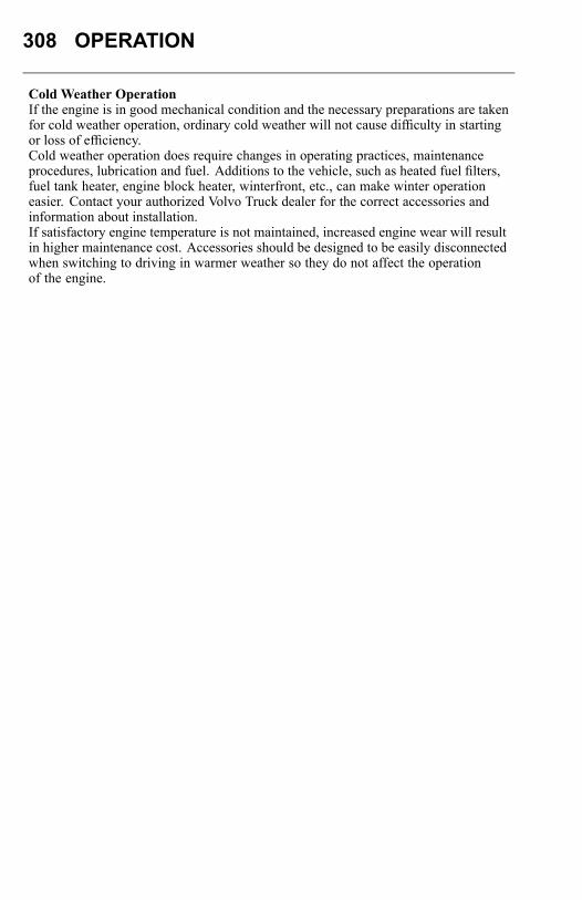
308 OPERATION
Cold Weather OperationIf the engine is in good mechanical condition and the necessary preparations are takenfor cold weather operation, ordinary cold weather will not cause difficulty in startingor loss of efficiency.Cold weather operation does require changes in operating practices, maintenanceprocedures, lubrication and fuel. Additions to the vehicle, such as heated fuel filters,fuel tank heater, engine block heater, winterfront, etc., can make winter operationeasier. Contact your authorized Volvo Truck dealer for the correct accessories andinformation about installation.If satisfactory engine temperature is not maintained, increased engine wear will resultin higher maintenance cost. Accessories should be designed to be easily disconnectedwhen switching to driving in warmer weather so they do not affect the operationof the engine.
OPERATION 309
For cold weather operation, follow these recommendations:
• When starting the engine in temperatures below 15°C (5°F), use engine lubricantsof lower viscosity. See the Operator’s Manual Vehicle Maintenance for additionalinformation.
• When the temperature is below freezing, make sure the concentration of antifreezein the coolant is sufficient to prevent freezing. Refer to the Operator’s ManualVehicle Maintenance for additional information.
• During cold weather, pay more attention to the condition of the batteries. Test themfrequently to ensure sufficient power for starting. A dead battery may freeze.
• Fuel cloud point is the temperature at which wax crystals become visible, which isgenerally above the pour point of the fuel. To keep the fuel filter elements fromplugging with wax crystals, the cloud point should be no higher than the lowestambient temperature at which the engine must start
To prevent wear and possible damage to the engine when it is cold, gradually bringit up to operating temperature before operating at high engine speeds or full load.After starting and before moving the vehicle, run the engine at 800 to 1000 rpm for3 to 5 minutes. Operate at partial engine load until the coolant temperature reaches75°C (165°F).
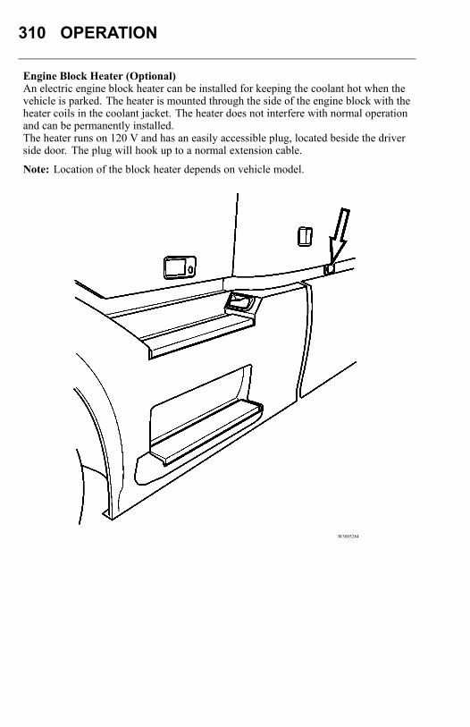
310 OPERATION
Engine Block Heater (Optional)An electric engine block heater can be installed for keeping the coolant hot when thevehicle is parked. The heater is mounted through the side of the engine block with theheater coils in the coolant jacket. The heater does not interfere with normal operationand can be permanently installed.The heater runs on 120 V and has an easily accessible plug, located beside the driverside door. The plug will hook up to a normal extension cable.
Note: Location of the block heater depends on vehicle model.
W3005284
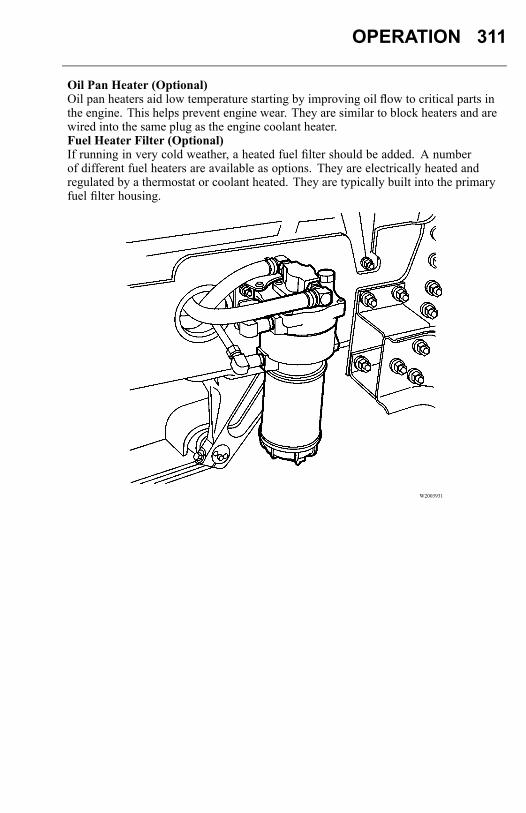
OPERATION 311
Oil Pan Heater (Optional)Oil pan heaters aid low temperature starting by improving oil flow to critical parts inthe engine. This helps prevent engine wear. They are similar to block heaters and arewired into the same plug as the engine coolant heater.Fuel Heater Filter (Optional)If running in very cold weather, a heated fuel filter should be added. A numberof different fuel heaters are available as options. They are electrically heated andregulated by a thermostat or coolant heated. They are typically built into the primaryfuel filter housing.
W2003931
312 OPERATION
Fuel Tank Heater (Optional)An in-tank fuel heater is also available. In-tank heaters use hot engine coolant towarm the fuel. This prevents wax formation in the fuel during cold season operation.These heaters are thermostatically controlled and will automatically raise the fueltemperature to an optimum level.WinterfrontVolvo Trucks North America does not recommend the use of winterfronts,shutters or any other shield in front of the grille or radiator package undernormal circumstances.Today’s electronically controlled engines are designed to operate in cold temperatureswithout a winterfront. These devices, if not used properly, can cause higher exhausttemperatures, power loss, excessive fan usage, failure of the charge-air-cooler and areduction in fuel economy.Winterfronts are properly used in the wintertime during very cold weather. In thesecases, coolant and inlet manifold temperatures must also be carefully monitored andcontrolled.
CAUTION
Failure to remove the winterfrontwhen temperatures go above severelycold temperatures could cause severedamage to engine, charge-air-coolerand/or loss of fuel economy.
If a winterfront is used, it must conform to these specifications:
• The grille coverage should be such that airflow through to the charge-air-cooler isat a uniform rate over the entire area. This means that a single, small opening inthe winterfront is not acceptable.
• Air passage must be distributed evenly across the grille and no more than 85%can be covered.
Please see your authorized Volvo Truck dealer for Volvo recommended winterfronts.
Note: If there is engine or related damage that can be traced to an improperly usedwinterfront, the warranty is no longer valid for those parts.
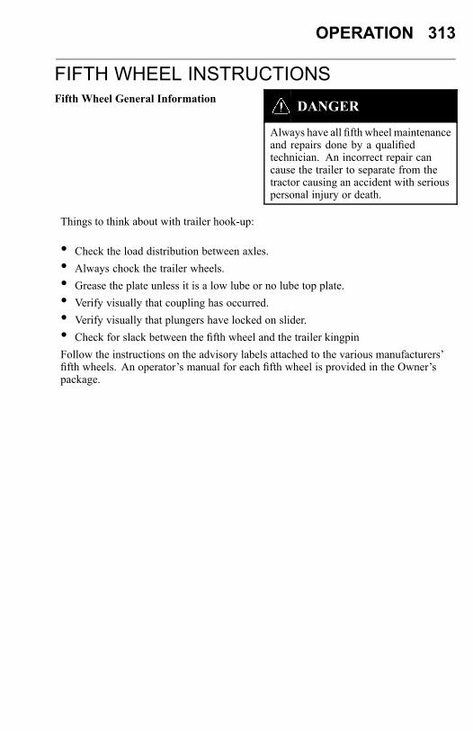
OPERATION 313
FIFTH WHEEL INSTRUCTIONSFifth Wheel General Information DANGER
Always have all fifth wheel maintenanceand repairs done by a qualifiedtechnician. An incorrect repair cancause the trailer to separate from thetractor causing an accident with seriouspersonal injury or death.
Things to think about with trailer hook-up:
• Check the load distribution between axles.• Always chock the trailer wheels.• Grease the plate unless it is a low lube or no lube top plate.• Verify visually that coupling has occurred.• Verify visually that plungers have locked on slider.• Check for slack between the fifth wheel and the trailer kingpinFollow the instructions on the advisory labels attached to the various manufacturers’fifth wheels. An operator’s manual for each fifth wheel is provided in the Owner’spackage.
314 OPERATION
If the fifth wheel is equipped with a sliding mounting, follow the advisory labelsattached to the component. Also, read the literature provided by the manufacturer.
DANGER
Always keep the fifth wheel plate welllubricated to prevent binding betweenthe tractor and trailer. A binding fifthwheel could cause erratic steering andloss of vehicle control that may result inserious personal injury or death.
There are three operating positions for the fifth wheel locking mechanism (ASF fifthwheel is shown as a typical fifth wheel):Locked— This is the position that the fifth wheel will be in with a trailer hookedup. In the locked position, the operating rod is retracted and the safety latch willfreely swing back and forth.
W9000180
Lockset— This is the position the fifth wheel is in when uncoupling the trailer. Toachieve the lockset position, the operating rod is pulled out with a slight upwardmotion. The operating rod shoulder will catch on the plate casting. The safety latch isrotated toward the rear of the fifth wheel.

OPERATION 315
W9000242
Open—This is the position the fifth wheel is in after the trailer is uncoupled. The jawis open and the operating rod is now dropped down and can be freely moved around.The safety latch is rotated toward the rear of the fifth wheel. This is the position thefifth wheel must be in when being coupled to a trailer.
W9000203
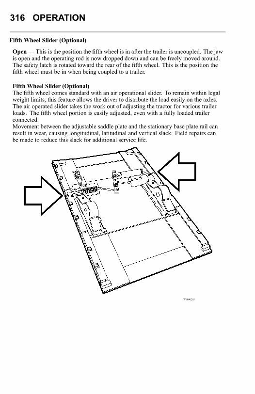
316 OPERATION
Fifth Wheel Slider (Optional)
Open—This is the position the fifth wheel is in after the trailer is uncoupled. The jawis open and the operating rod is now dropped down and can be freely moved around.The safety latch is rotated toward the rear of the fifth wheel. This is the position thefifth wheel must be in when being coupled to a trailer.
Fifth Wheel Slider (Optional)The fifth wheel comes standard with an air operational slider. To remain within legalweight limits, this feature allows the driver to distribute the load easily on the axles.The air operated slider takes the work out of adjusting the tractor for various trailerloads. The fifth wheel portion is easily adjusted, even with a fully loaded trailerconnected.Movement between the adjustable saddle plate and the stationary base plate rail canresult in wear, causing longitudinal, latitudinal and vertical slack. Field repairs canbe made to reduce this slack for additional service life.
W9000205
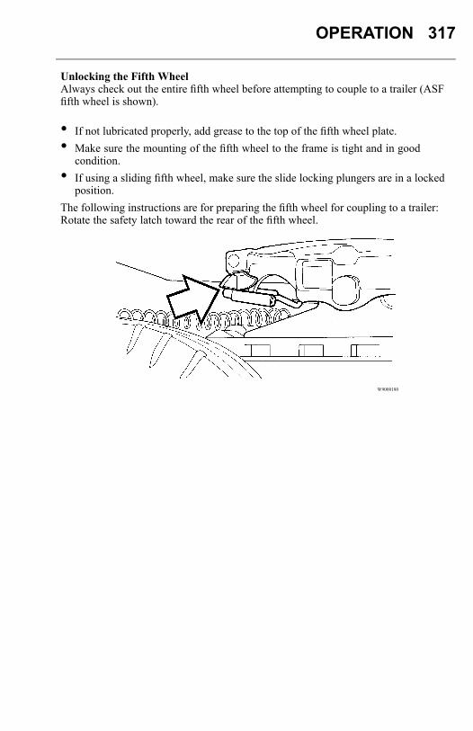
OPERATION 317
Unlocking the Fifth WheelAlways check out the entire fifth wheel before attempting to couple to a trailer (ASFfifth wheel is shown).
• If not lubricated properly, add grease to the top of the fifth wheel plate.• Make sure the mounting of the fifth wheel to the frame is tight and in good
condition.• If using a sliding fifth wheel, make sure the slide locking plungers are in a locked
position.The following instructions are for preparing the fifth wheel for coupling to a trailer:Rotate the safety latch toward the rear of the fifth wheel.
W9000180
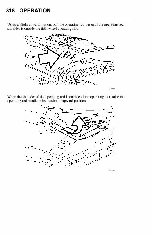
318 OPERATION
Using a slight upward motion, pull the operating rod out until the operating rodshoulder is outside the fifth wheel operating slot.
W9000202
When the shoulder of the operating rod is outside of the operating slot, raise theoperating rod handle to its maximum upward position.
W9000242
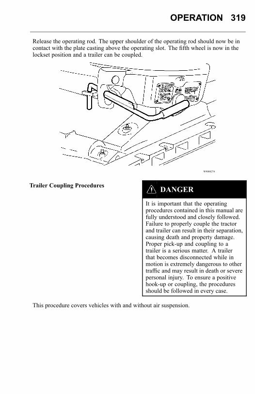
OPERATION 319
Release the operating rod. The upper shoulder of the operating rod should now be incontact with the plate casting above the operating slot. The fifth wheel is now in thelockset position and a trailer can be coupled.
W9000274
Trailer Coupling Procedures DANGER
It is important that the operatingprocedures contained in this manual arefully understood and closely followed.Failure to properly couple the tractorand trailer can result in their separation,causing death and property damage.Proper pick-up and coupling to atrailer is a serious matter. A trailerthat becomes disconnected while inmotion is extremely dangerous to othertraffic and may result in death or severepersonal injury. To ensure a positivehook-up or coupling, the proceduresshould be followed in every case.
This procedure covers vehicles with and without air suspension.
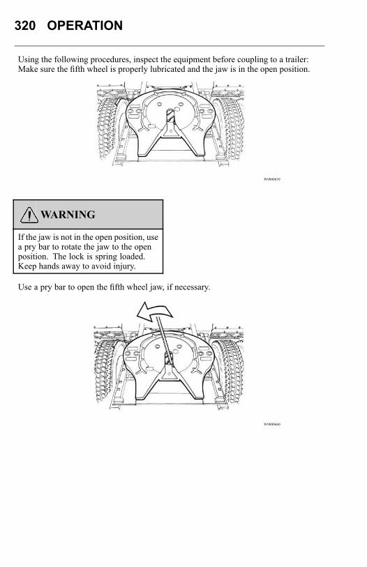
320 OPERATION
Using the following procedures, inspect the equipment before coupling to a trailer:Make sure the fifth wheel is properly lubricated and the jaw is in the open position.
W9000659
WARNING
If the jaw is not in the open position, usea pry bar to rotate the jaw to the openposition. The lock is spring loaded.Keep hands away to avoid injury.
Use a pry bar to open the fifth wheel jaw, if necessary.
W9000660
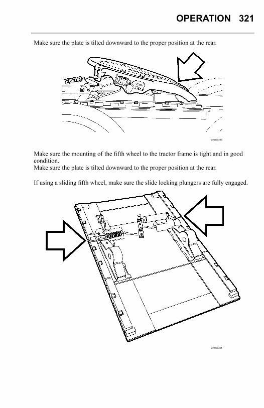
OPERATION 321
Make sure the plate is tilted downward to the proper position at the rear.
W9000236
Make sure the mounting of the fifth wheel to the tractor frame is tight and in goodcondition.Make sure the plate is tilted downward to the proper position at the rear.
If using a sliding fifth wheel, make sure the slide locking plungers are fully engaged.
W9000205
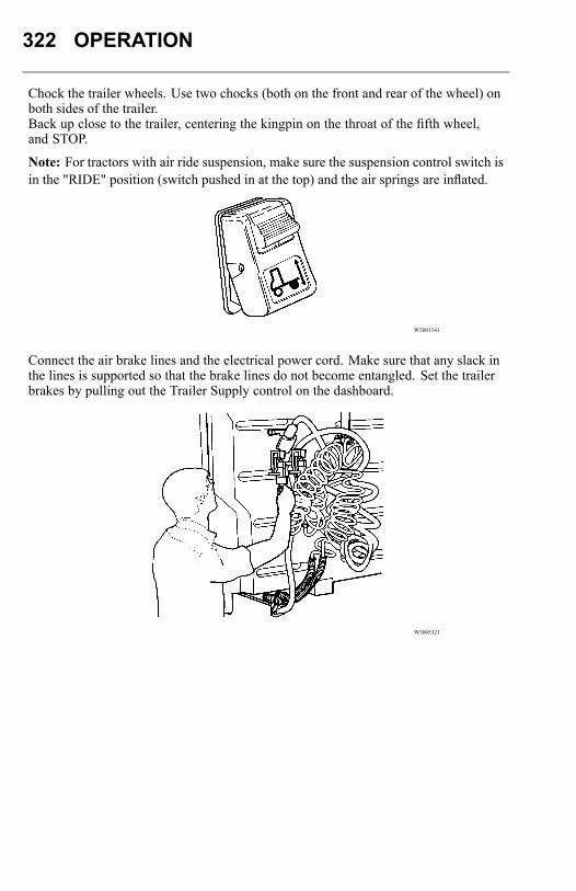
322 OPERATION
Chock the trailer wheels. Use two chocks (both on the front and rear of the wheel) onboth sides of the trailer.Back up close to the trailer, centering the kingpin on the throat of the fifth wheel,and STOP.
Note: For tractors with air ride suspension, make sure the suspension control switch isin the "RIDE" position (switch pushed in at the top) and the air springs are inflated.
W3001341
Connect the air brake lines and the electrical power cord. Make sure that any slack inthe lines is supported so that the brake lines do not become entangled. Set the trailerbrakes by pulling out the Trailer Supply control on the dashboard.
W3005321
OPERATION 323
CAUTION
Attempting to couple with the trailerat an improper height could result ina false or improper couple and causedamage to the tractor, fifth wheel andtrailer.
Check to see that the trailer is at the proper height for coupling. The leading edge ofthe trailer plate should initially contact the fifth wheel top plate surface about 200 mm(8 in.) behind the pivot point as the tractor backs under the trailer. Raise or lower thetrailer landing gear as required to obtain this position.Back under the trailer, keep the trailer kingpin centered in the throat of the fifth wheel.After picking up the trailer — STOP — then continue backing until the fifth wheellocks firmly on the kingpin. Stopping helps prevent hitting the kingpin too hard.
DANGER
To ensure a positive hook-up orcoupling, these procedures should befollowed in every case. A trailer that isnot connected correctly may disconnectfrom the tractor while in motion,resulting in an accident, personal injuryor death.
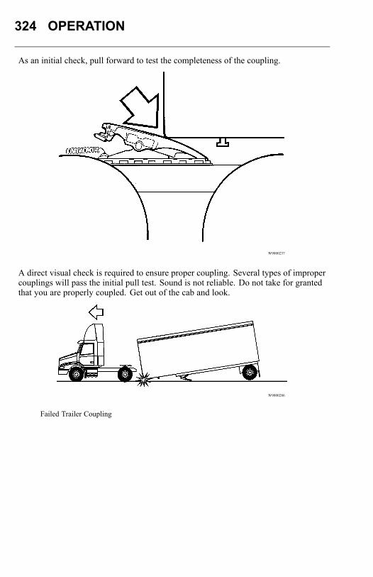
324 OPERATION
As an initial check, pull forward to test the completeness of the coupling.
W9000237
A direct visual check is required to ensure proper coupling. Several types of impropercouplings will pass the initial pull test. Sound is not reliable. Do not take for grantedthat you are properly coupled. Get out of the cab and look.
W9000286
Failed Trailer Coupling

OPERATION 325
Make sure the trailer kingpin is in the jaw slot and that the jaw is closed behind the pin.The kingpin should not overhang the fifth wheel or be caught in the grease groove.To verify that the kingpin is actually in the fifth wheel slot and the jaw is closed, thepin must be visually inspected from the rear. Use a flashlight if necessary.
W9000181
Make sure the trailer bed is resting on the top surface of the fifth wheel plate, and thatthere is no visible gap between the fifth wheel and the trailer bed plate.
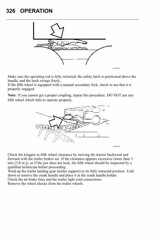
326 OPERATION
W9000240
Make sure the operating rod is fully retracted, the safety latch is positioned above thehandle, and the latch swings freely.If the fifth wheel is equipped with a manual secondary lock, check to see that it isproperly engaged.
Note: If you cannot get a proper coupling, repeat this procedure. DO NOT use anyfifth wheel which fails to operate properly.
W9000180
Check the kingpin to fifth wheel clearance by moving the tractor backward andforward with the trailer brakes set. If the clearance appears excessive (more than 3mm [1/8 in.]), or if the jaw does not lock, the fifth wheel should be inspected by aqualified technician before proceeding.Wind up the trailer landing gear (trailer support) to its fully retracted position. Folddown or remove the crank handle and place it in the crank handle holder.Check the air brake lines and the trailer light cord connections.Remove the wheel chocks from the trailer wheels.
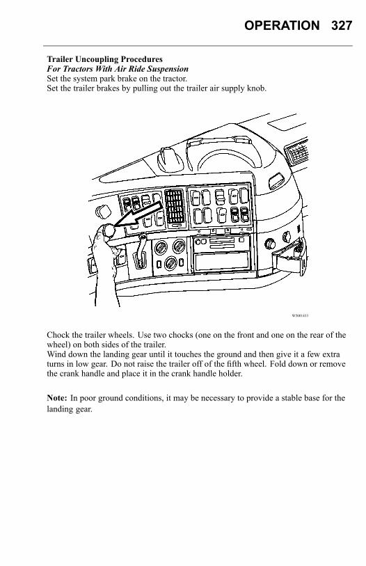
OPERATION 327
Trailer Uncoupling ProceduresFor Tractors With Air Ride SuspensionSet the system park brake on the tractor.Set the trailer brakes by pulling out the trailer air supply knob.
W5001433
Chock the trailer wheels. Use two chocks (one on the front and one on the rear of thewheel) on both sides of the trailer.Wind down the landing gear until it touches the ground and then give it a few extraturns in low gear. Do not raise the trailer off of the fifth wheel. Fold down or removethe crank handle and place it in the crank handle holder.
Note: In poor ground conditions, it may be necessary to provide a stable base for thelanding gear.
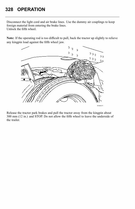
328 OPERATION
Disconnect the light cord and air brake lines. Use the dummy air couplings to keepforeign material from entering the brake lines.Unlock the fifth wheel.
Note: If the operating rod is too difficult to pull, back the tractor up slightly to relieveany kingpin load against the fifth wheel jaw.
W9000275
Release the tractor park brakes and pull the tractor away from the kingpin about300 mm (12 in.) and STOP. Do not allow the fifth wheel to leave the underside ofthe trailer.
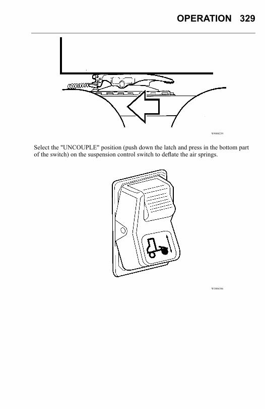
OPERATION 329
W9000239
Select the "UNCOUPLE" position (push down the latch and press in the bottom partof the switch) on the suspension control switch to deflate the air springs.
W3006386
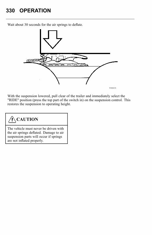
330 OPERATION
Wait about 30 seconds for the air springs to deflate.
W9000238
With the suspension lowered, pull clear of the trailer and immediately select the"RIDE" position (press the top part of the switch in) on the suspension control. Thisrestores the suspension to operating height.
CAUTION
The vehicle must never be driven withthe air springs deflated. Damage to airsuspension parts will occur if springsare not inflated properly.
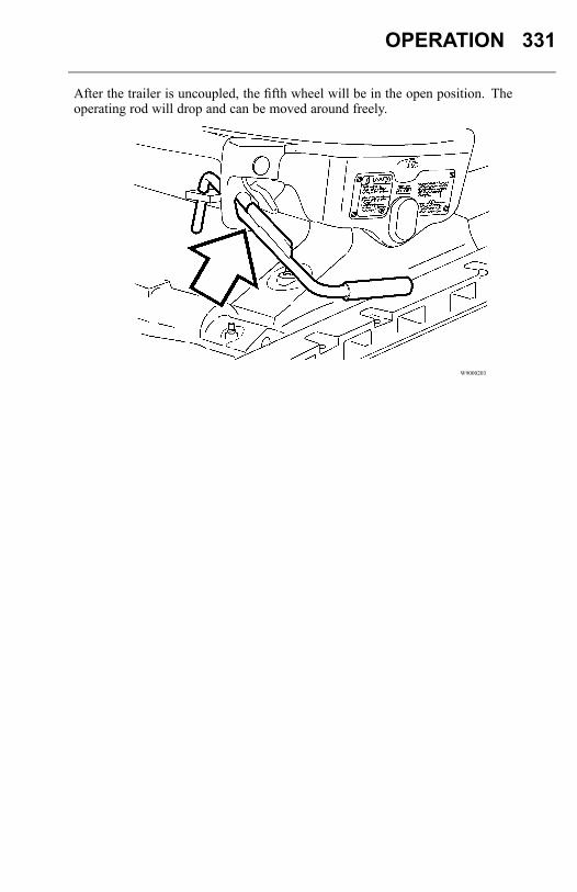
OPERATION 331
After the trailer is uncoupled, the fifth wheel will be in the open position. Theoperating rod will drop and can be moved around freely.
W9000203
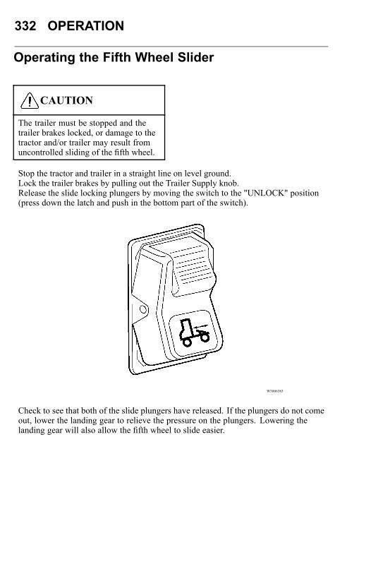
332 OPERATION
Operating the Fifth Wheel Slider
CAUTION
The trailer must be stopped and thetrailer brakes locked, or damage to thetractor and/or trailer may result fromuncontrolled sliding of the fifth wheel.
Stop the tractor and trailer in a straight line on level ground.Lock the trailer brakes by pulling out the Trailer Supply knob.Release the slide locking plungers by moving the switch to the "UNLOCK" position(press down the latch and push in the bottom part of the switch).
W3006383
Check to see that both of the slide plungers have released. If the plungers do not comeout, lower the landing gear to relieve the pressure on the plungers. Lowering thelanding gear will also allow the fifth wheel to slide easier.
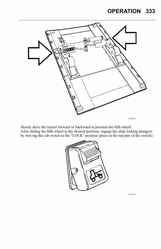
OPERATION 333
W9000205
Slowly drive the tractor forward or backward to position the fifth wheel.After sliding the fifth wheel to the desired position, engage the slide locking plungersby moving the cab switch to the "LOCK" position (press in the top part of the switch).
W3001346
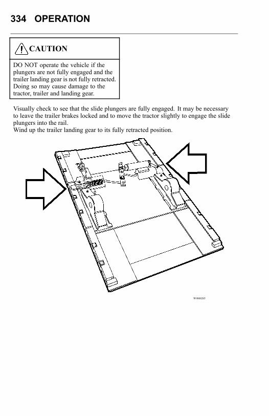
334 OPERATION
CAUTION
DO NOT operate the vehicle if theplungers are not fully engaged and thetrailer landing gear is not fully retracted.Doing so may cause damage to thetractor, trailer and landing gear.
Visually check to see that the slide plungers are fully engaged. It may be necessaryto leave the trailer brakes locked and to move the tractor slightly to engage the slideplungers into the rail.Wind up the trailer landing gear to its fully retracted position.
W9000205
OPERATION 335
Clutch
GeneralDANGER
Before starting the engine, setthe parking brakes and place thetransmission in neutral. Failure to doso can result in unexpected vehiclemovement and can cause seriouspersonal injury and death.
DO NOT allow the clutch to slip excessively. This would cause excessive heat tobe generated and the clutch will be damaged and bring on premature failure. Assoon as the vehicle is moving, remove the foot from the pedal for complete clutchengagement. Once the clutch is fully engaged, heat and wear does not affect it.DO NOT shock load the drive line through rapid engagement of the clutch. Extremecare should be taken when driving heavy loads up hills. Always use the lowest gearwhen starting out under adverse conditions.When operating a vehicle equipped with a clutch brake, the clutch pedal should not bedepressed more than halfway to the floor while shifting, except when the vehicle isat a stop. To re-enter the low gear from neutral or reverse, or to enter reverse gearfrom neutral or low, the clutch should be depressed all the way to engage the clutchbrake. This stops the rotation of the transmission input shaft and provides an easy,quiet gear engagement.
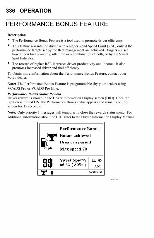
336 OPERATION
PERFORMANCE BONUS FEATUREDescription• The Performance Bonus Feature is a tool used to promote driver efficiency.• This feature rewards the driver with a higher Road Speed Limit (RSL) only if the
performance targets set by the fleet management are achieved. Targets are setbased upon fuel economy, idle time or a combination of both, or by the SweetSpot Indicator.
• The reward of higher RSL increases driver productivity and income. It alsopromotes increased driver and fuel efficiency.
To obtain more information about the Performance Bonus Feature, contact yourVolvo dealer.
Note: The Performance Bonus Feature is programmable (by your dealer) usingVCADS Pro or VCADS Pro Elite.Performance Bonus Status RewardDriver reward is shown in the Driver Information Display screen (DID). Once theignition is turned ON, the Performance Bonus status appears and remains on thescreen for 15 seconds.
Note: Only priority 1 messages will temporarily close the rewards status menu. Foradditional information about the DID, refer to the Driver Information Display Manual.
W3028719
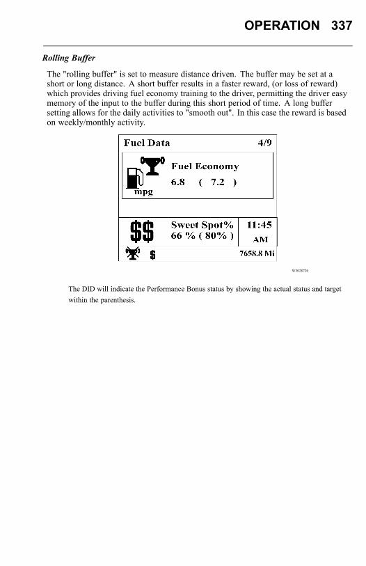
OPERATION 337
Rolling Buffer
The "rolling buffer" is set to measure distance driven. The buffer may be set at ashort or long distance. A short buffer results in a faster reward, (or loss of reward)which provides driving fuel economy training to the driver, permitting the driver easymemory of the input to the buffer during this short period of time. A long buffersetting allows for the daily activities to "smooth out". In this case the reward is basedon weekly/monthly activity.
W3028720
The DID will indicate the Performance Bonus status by showing the actual status and targetwithin the parenthesis.
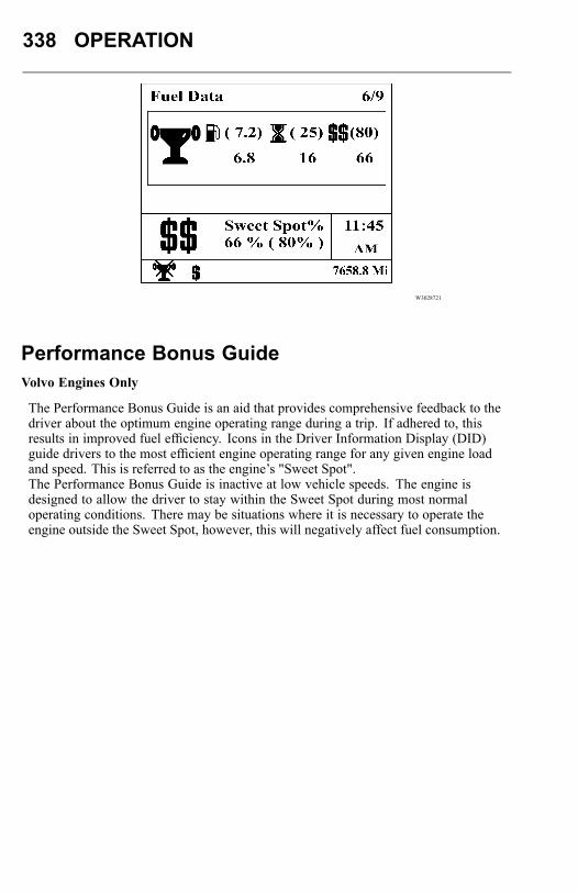
338 OPERATION
W3028721
Performance Bonus GuideVolvo Engines Only
The Performance Bonus Guide is an aid that provides comprehensive feedback to thedriver about the optimum engine operating range during a trip. If adhered to, thisresults in improved fuel efficiency. Icons in the Driver Information Display (DID)guide drivers to the most efficient engine operating range for any given engine loadand speed. This is referred to as the engine’s "Sweet Spot".The Performance Bonus Guide is inactive at low vehicle speeds. The engine isdesigned to allow the driver to stay within the Sweet Spot during most normaloperating conditions. There may be situations where it is necessary to operate theengine outside the Sweet Spot, however, this will negatively affect fuel consumption.
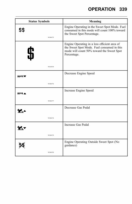
OPERATION 339
Status Symbols Meaning
W3006755
Engine Operating in the Sweet Spot Mode. Fuelconsumed in this mode will count 100% towardthe Sweet Spot Percentage.
W3028749
Engine Operating in a less efficient area ofthe Sweet Spot Mode. Fuel consumed in thismode will count 50% toward the Sweet SpotPercentage.
W3006756
Decrease Engine Speed
W3006757
Increase Engine Speed
W3006758
Decrease Gas Pedal
W3006759
Increase Gas Pedal
W3006760
Engine Operating Outside Sweet Spot (Noguidance)
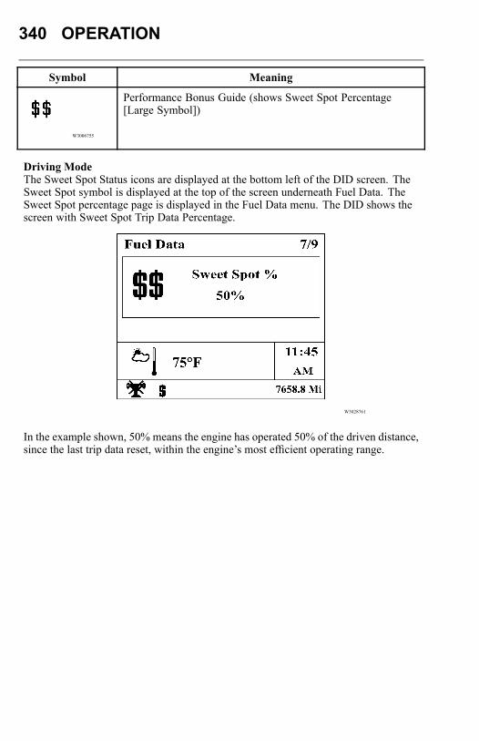
340 OPERATION
Symbol Meaning
W3006755
Performance Bonus Guide (shows Sweet Spot Percentage[Large Symbol])
Driving ModeThe Sweet Spot Status icons are displayed at the bottom left of the DID screen. TheSweet Spot symbol is displayed at the top of the screen underneath Fuel Data. TheSweet Spot percentage page is displayed in the Fuel Data menu. The DID shows thescreen with Sweet Spot Trip Data Percentage.
W3028761
In the example shown, 50% means the engine has operated 50% of the driven distance,since the last trip data reset, within the engine’s most efficient operating range.
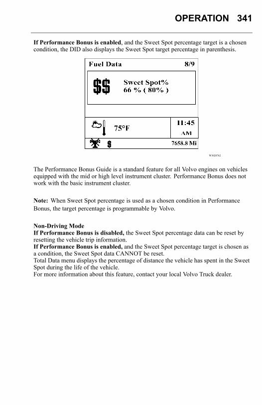
OPERATION 341
If Performance Bonus is enabled, and the Sweet Spot percentage target is a chosencondition, the DID also displays the Sweet Spot target percentage in parenthesis.
W3028762
The Performance Bonus Guide is a standard feature for all Volvo engines on vehiclesequipped with the mid or high level instrument cluster. Performance Bonus does notwork with the basic instrument cluster.
Note: When Sweet Spot percentage is used as a chosen condition in PerformanceBonus, the target percentage is programmable by Volvo.
Non-Driving ModeIf Performance Bonus is disabled, the Sweet Spot percentage data can be reset byresetting the vehicle trip information.If Performance Bonus is enabled, and the Sweet Spot percentage target is chosen asa condition, the Sweet Spot data CANNOT be reset.Total Data menu displays the percentage of distance the vehicle has spent in the SweetSpot during the life of the vehicle.For more information about this feature, contact your local Volvo Truck dealer.
342 OPERATION
AXLESDifferential Locks
DANGER
DO NOT drive on dry, paved surfacewith the differential locks engaged.The vehicle will strive to maintain astraight line. Taking a curve with thedifferential locks engaged may causean accident, leading to serious personalinjury or death.
CAUTION
Never operate the vehicle with thedifferentials locked any longer than isnecessary, as this places a great strain onthe axles and may cause rapid tire wear.
Under normal traction conditions, do not engage the differential locks. If at allpossible, do not use the differential locks while taking a curve. With good tractionand the differential locks engaged, the vehicle will be understeered and therefore willtend to drive straight in a curve. When using locks on good traction surface, drivecautiously and do not exceed 40 km/h (25 mph). Disengage the locks as soon aspossible.When the differential locks are disengaged, the couplings may be under tension.Disengage the locks by returning the switch to the OFF position. Help with thedisengagement by briefly letting up on the accelerator to relieve the torque on thecouplings.The drive axle(s) may be equipped with differential locks. The single drive axle willonly have a wheel differential lock. With tandem drive axles, there could be bothwheel differential locks and an inter-axle differential lock.
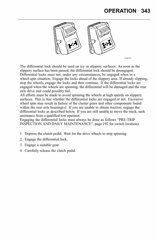
OPERATION 343
W3001991
The differential lock should be used on icy or slippery surfaces. As soon as theslippery surface has been passed, the differential lock should be disengaged.Differential locks must not, under any circumstances, be engaged when in awheel-spin situation. Engage the locks ahead of the slippery area. If already slipping,stop the wheels, engage the locks and then continue. If the differential locks areengaged when the wheels are spinning, the differential will be damaged and the rearaxle drive unit could possibly fail.All efforts must be made to avoid spinning the wheels at high speeds on slipperysurfaces. This is true whether the differential locks are engaged or not. Excessivewheel spin may result in failure of the cluster gears and other components foundwithin the rear axle housing(s). If you are unable to obtain traction, engage thedifferential locks as described below. If you are still unable to move the truck, seekassistance from a qualified tow operator.Engaging the differential locks must always be done as follows “PRE-TRIPINSPECTION AND DAILY MAINTENANCE”, page 192 for switch location):
1 Depress the clutch pedal. Wait for the drive wheels to stop spinning.2 Engage the differential lock.3 Engage a suitable gear.4 Carefully release the clutch pedal.
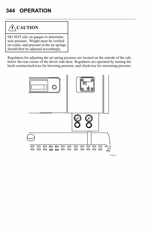
344 OPERATION
CAUTION
DO NOT rely on gauges to determineaxle pressure. Weight must be verifiedon scales, and pressure in the air springsshould then be adjusted accordingly.
Regulators for adjusting the air spring pressure are located on the outside of the cab,below the rear corner of the driver side door. Regulators are operated by turning theknob counterclockwise for lowering pressure, and clockwise for increasing pressure.
W7001173
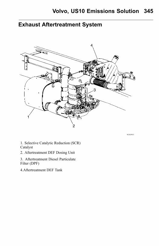
Volvo, US10 Emissions Solution 345
Exhaust Aftertreatment System
W2029933
1. Selective Catalytic Reduction (SCR)Catalyst2. Aftertreatment DEF Dosing Unit
3. Aftertreatment Diesel ParticulateFilter (DPF)
4.Aftertreatment DEF Tank
346 Volvo, US10 Emissions Solution
Safety InformationVolvo utilizes the use of a Diesel Particulate Filter (DPF) and Selective CatalyticReduction (SCR) to meet EPA2010 emissions. The system is designed to require verylittle driver interface to maintain correct operation. The technology utilizes a passiveregeneration; requiring no fuel to be injected to clean the DPF. In EPA2007 an activeregeneration (fuel was injected) was required to clean out the DPF producing veryhigh exhaust outlet temperatures. Certain vocational duty cycles will require the useof fuel and/or a parked regeneration to clean out built-up soot in the particulate filter.Exhaust temperature will increase during a parked regeneration. When parking thevehicle to perform a parked regeneration keep away from any flammable material,vapors or structures.
DANGER
Exhaust gases and components canbe at extremely high temperaturesduring regeneration. When parking thevehicle, keep away from any flammablematerials, vapors, or structures.
DANGER
The temperature of the exhaust systemcomponents during the regenerationprocess can exceed 350 degrees C(660 F). The exhaust gas leavingthe system can reach 420 degrees C(788 F). Various factors (includingambient temperature and duration of theregeneration process) determine whenthese components will return to normaloperating temperature after regenerationhas completed. Be extremely carefularound these hot components. Contactwith these components can result inserious personal injury.
Volvo, US10 Emissions Solution 347
Exhaust Aftertreatment System Componentsand Operation
Selective Catalytic Reduction (SCR)
Selective Catalytic Reduction (SCR) is an emissions-reduction technology with theability to deliver near-zero emissions of nitrogen oxides (NOx), a smog-causingpollutant and greenhouse gas. SCR’s performance has been proved in millions ofmiles of real-world truck operations in other countries, as well as in long-term fieldtests in the U.S.
SCR reduces NOx emissions to very low levels, while at the same time deliveringexcellent fuel economy and reliability. The system doesn’t change the design oroperation of the basic engine. Rather, SCR is an Aftertreatment system whichconverts NOx in the exhaust stream into harmless gases. Modern diesels already useexhaust Aftertreatment systems, called diesel particulate filters, to control emissionsof another pollutant, soot (also known as particulate matter or PM).
SCR works by injecting Diesel Exhaust Fluid (DEF) into the exhaust. DEF is asolution of ultra- pure water and urea. DEF works with the heat of the exhaust anda catalyst to convert NOx into nitrogen and water vapor - two harmless and naturalcomponents of the air we breathe. The end result is cleaner air, excellent fuelefficiency and a reliable emissions control system for today’s modern diesel engine.

348 Volvo, US10 Emissions Solution
W2031651
1. Diesel Engine
2. Aftertreatment DEF Tank
3. Aftertreatment DEF Pump
4. Aftertreatment DEF Dosing Unit
5. Aftertreatment Diesel Particulate Filter (DPF)
6. Selective Catalytic Reduction (SCR) Catalyst
7. Aftertreatment DEF Tank Gauge
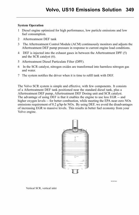
Volvo, US10 Emissions Solution 349
System Operation1 Diesel engine optimized for high performance, low particle emissions and low
fuel consumption.2 Aftertreatment DEF tank3 The Aftertreatment Control Module (ACM) continuously monitors and adjusts the
Aftertreatment DEF pump pressure in response to current engine load conditions.4 DEF is injected into the exhaust gases in between the Aftertreatment DPF (5)
and the SCR catalyst (6).5 Aftertreatment Diesel Particulate Filter (DPF).6 In the SCR catalyst, nitrogen oxides are transformed into harmless nitrogen gas
and water.7 The system notifies the driver when it is time to refill tank with DEF.
The Volvo SCR system is simple and effective, with few components. It consistsof a Aftertreatment DEF tank positioned near the standard diesel tank, plus aAftertreatment DEF pump, Aftertreatment DEF Dosing unit and SCR catalyst.The advantage of using DEF is that it enables the engine to use less EGR -- andhigher oxygen levels -- for better combustion, while meeting the EPA near-zero NOxemissions requirement of 0.2 g/hp-hr NOx. By using DEF, we avoid the disadvantagesof increasing EGR to massive levels. This results in better fuel economy from yourVolvo engine.
W2055491
Vertical SCR, vertical inlet

350 Volvo, US10 Emissions Solution
W2055492
Horizontal SCR, full sive
W2055493
Horizontal SCR, compact sive
CAUTION
Do not put diesel fuel in theAftertreatment DEF tank. Dieselfuel, if sprayed into the hot exhaustalong with the DEF, could igniteexplosively causing a fire resultingin personal injury or damage to theexhaust system.
Volvo, US10 Emissions Solution 351
W3036787
Diesel Exhaust Fluid (DEF)
Diesel Exhaust Fluid (DEF) is a reactant that’s key to the SCR process. It’s a nontoxic,aqueous solution of urea and ultra-pure water. Urea is a compound of nitrogen thatturns to ammonia when heated. The fluid is non flammable, and is not dangerous whenhandled as recommended. However, it is highly corrosive to certain metals, espicallycopper and brass. Read the separate section concerning the handling of DEF solution.Use only Diesel Exhaust Fluid that is clearly labeled as meeting ISO-22241standards, and certified by the American Petroleum Institute. The container mustdisplay the API certification seal. Never use agricultural or industrial gradeurea. Use of fluids other than API certified Diesel Exhaust Fluid will compromiseaftertreatment system performance, increase emissions, and may impact your productwarranties. Never dilute DEF with water or any other fluid.It is recommended that DEF not be stored in extreme hot or cold conditions, orfor prolonged periods. Follow the instructions for proper storage and handling asindicated on the container or provided with the purchase.
Note: Agriculture mixtures are not pure enough for use in the SCR system andimpurities in the solution will comprise the SCR system.
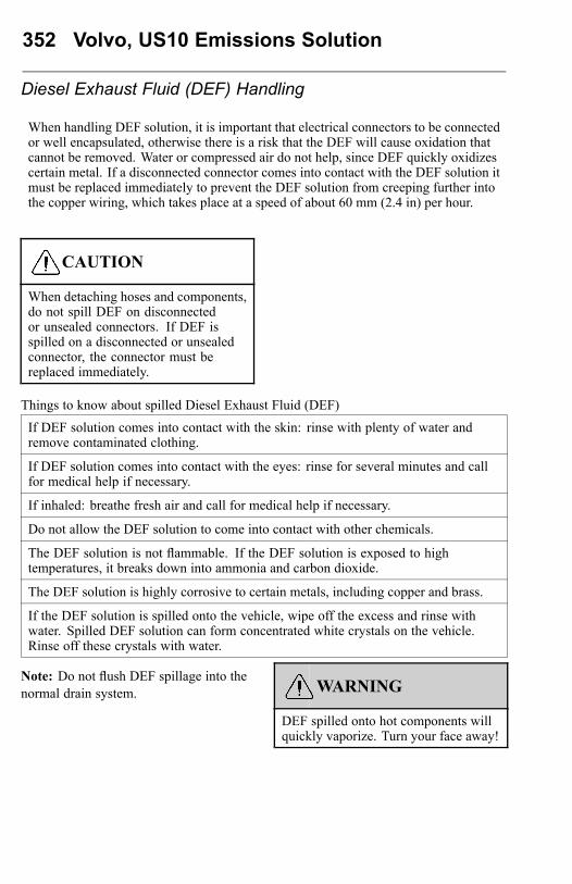
352 Volvo, US10 Emissions Solution
Diesel Exhaust Fluid (DEF) Handling
When handling DEF solution, it is important that electrical connectors to be connectedor well encapsulated, otherwise there is a risk that the DEF will cause oxidation thatcannot be removed. Water or compressed air do not help, since DEF quickly oxidizescertain metal. If a disconnected connector comes into contact with the DEF solution itmust be replaced immediately to prevent the DEF solution from creeping further intothe copper wiring, which takes place at a speed of about 60 mm (2.4 in) per hour.
CAUTION
When detaching hoses and components,do not spill DEF on disconnectedor unsealed connectors. If DEF isspilled on a disconnected or unsealedconnector, the connector must bereplaced immediately.
Things to know about spilled Diesel Exhaust Fluid (DEF)
If DEF solution comes into contact with the skin: rinse with plenty of water andremove contaminated clothing.
If DEF solution comes into contact with the eyes: rinse for several minutes and callfor medical help if necessary.
If inhaled: breathe fresh air and call for medical help if necessary.
Do not allow the DEF solution to come into contact with other chemicals.
The DEF solution is not flammable. If the DEF solution is exposed to hightemperatures, it breaks down into ammonia and carbon dioxide.
The DEF solution is highly corrosive to certain metals, including copper and brass.
If the DEF solution is spilled onto the vehicle, wipe off the excess and rinse withwater. Spilled DEF solution can form concentrated white crystals on the vehicle.Rinse off these crystals with water.
Note: Do not flush DEF spillage into thenormal drain system. WARNING
DEF spilled onto hot components willquickly vaporize. Turn your face away!

Volvo, US10 Emissions Solution 353
Diesel Exhaust Fluid (DEF) Availability
DEF will be available in 2.5-gallon containers, 55-gallon drums, 275 gallon IBC andin bulk storage for fleet locations, truck stops and dealerships. All major truck stops,dealers and distributors will carry DEF.DEF will freezes to a "slush" type consistency at –11 degrees C (12 F), but not to asolid, so just as with diesel fuel, stored DEF needs to be protected from extendedperiods of severe cold. For more information on DEF and availability please visit thewebsite www.Volvoscr.com or call 1–800–52VOLVO.
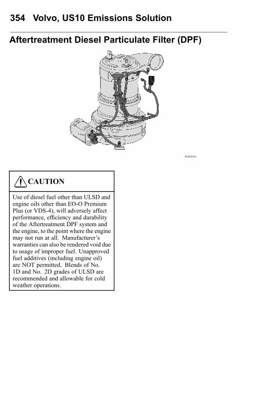
354 Volvo, US10 Emissions Solution
Aftertreatment Diesel Particulate Filter (DPF)
W2030326
CAUTION
Use of diesel fuel other than ULSD andengine oils other than EO-O PremiumPlus (or VDS-4), will adversely affectperformance, efficiency and durabilityof the Aftertreatment DPF system andthe engine, to the point where the enginemay not run at all. Manufacturer’swarranties can also be rendered void dueto usage of improper fuel. Unapprovedfuel additives (including engine oil)are NOT permitted. Blends of No.1D and No. 2D grades of ULSD arerecommended and allowable for coldweather operations.
Volvo, US10 Emissions Solution 355
The exhaust Aftertreatment system virtually eliminates exhaust smoke. WhiteExhaust vapor (water condensation) may be visible during a cold start. If blackexhaust smoke is visible during engine operation, this indicates a problem with theexhaust Aftertreatment system. Take the vehicle to an authorized Volvo Truck dealerimmediately.
Vehicles equipped with a 2010 emission compliant engine have an exhaustAftertreatment system which includes a Selective Catalytic Reduction (SCR) systemand a Catalyzed Aftertreatment Diesel Particulate Filter (DPF). The AftertreatmentDPF takes the place of the standard muffler, and it reduces soot and particulateemissions into the atmosphere. Soot and other particulate matter are collected by afilter where it is eventually oxidized. Vehicles equipped with a Aftertreatment DPFrequire the use of EO-O Premium Plus (or VDS-4) specification high performancediesel engine oil and Ultra Low Sulfur Diesel (ULSD) fuel.
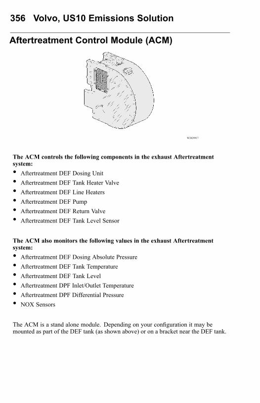
356 Volvo, US10 Emissions Solution
Aftertreatment Control Module (ACM)
W2029917
The ACM controls the following components in the exhaust Aftertreatmentsystem:• Aftertreatment DEF Dosing Unit• Aftertreatment DEF Tank Heater Valve• Aftertreatment DEF Line Heaters• Aftertreatment DEF Pump• Aftertreatment DEF Return Valve• Aftertreatment DEF Tank Level Sensor
The ACM also monitors the following values in the exhaust Aftertreatmentsystem:• Aftertreatment DEF Dosing Absolute Pressure• Aftertreatment DEF Tank Temperature• Aftertreatment DEF Tank Level• Aftertreatment DPF Inlet/Outlet Temperature• Aftertreatment DPF Differential Pressure• NOX Sensors
The ACM is a stand alone module. Depending on your configuration it may bemounted as part of the DEF tank (as shown above) or on a bracket near the DEF tank.

Volvo, US10 Emissions Solution 357
Exhaust Aftertreatment System Operation
The stalk switch control lever is used to interact with the Driver Information Display(DID) in the center of the instrument cluster. The lever is located on the right-handside of the steering wheel.
W3005262
1 Esc or Escape button is used to return to the previous menu or display.2 ↵↵↵ or Enter button is used to display a list of menus, open a menu, and select the
highlighted area.3 Up arrow button is used to scroll up through a menu.4 Down arrow button is used to scroll down through a menu.
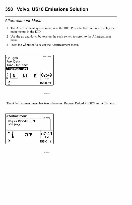
358 Volvo, US10 Emissions Solution
Aftertreatment Menu
1 The Aftertreatment system menu is in the DID. Press the Esc button to display themain menus in the DID.
2 Use the up and down buttons on the stalk switch to scroll to the Aftertreatmentmenu.
3 Press the↵↵↵ button to select the Aftertreatment menu.
W3007527
The Aftertreatment menu has two submenus: Request Parked REGEN and ATS status.
W3054903
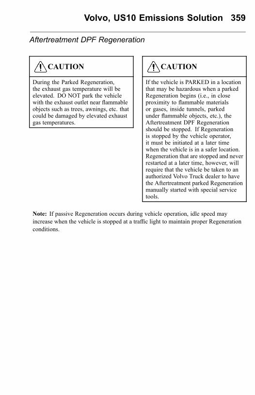
Volvo, US10 Emissions Solution 359
Aftertreatment DPF Regeneration
CAUTION
During the Parked Regeneration,the exhaust gas temperature will beelevated. DO NOT park the vehiclewith the exhaust outlet near flammableobjects such as trees, awnings, etc. thatcould be damaged by elevated exhaustgas temperatures.
CAUTION
If the vehicle is PARKED in a locationthat may be hazardous when a parkedRegeneration begins (i.e., in closeproximity to flammable materialsor gases, inside tunnels, parkedunder flammable objects, etc.), theAftertreatment DPF Regenerationshould be stopped. If Regenerationis stopped by the vehicle operator,it must be initiated at a later timewhen the vehicle is in a safer location.Regeneration that are stopped and neverrestarted at a later time, however, willrequire that the vehicle be taken to anauthorized Volvo Truck dealer to havethe Aftertreatment parked Regenerationmanually started with special servicetools.
Note: If passive Regeneration occurs during vehicle operation, idle speed mayincrease when the vehicle is stopped at a traffic light to maintain proper Regenerationconditions.
360 Volvo, US10 Emissions Solution
There are two types of Aftertreatment DPF Regeneration: Passive regeneration andParked regeneration.Passive Regeneration occurs when the exhaust gas within the aftertreatment systemis hot enough to burn soot without injecting additional fuel into the DPF system.On chassis equipped with a US07 aftertreatment system, DPF”s needed an activeregeneration, that includes this injection of fuel. With the addition of the SCR systemactive regenerations are no longer needed in US10.Parked regeneration is initated manually by the driver when alerted by the dash.The vehicle must be stationary to begin the regeneration, and remain stationary tocomplete.The Aftertreatment DPF Regeneration system is self-monitoring. Under certain dutycycles driver action is needed to perform a parked regeneration. When driver action isneeded to perform a parked regeneration the Aftertreatment DPF Regeneration Neededicon on the instrument cluster flashes and the message “Parked REGEN Needed” isdisplayed. Initiate a parked Aftertreatment DPF regeneration at the next stop.
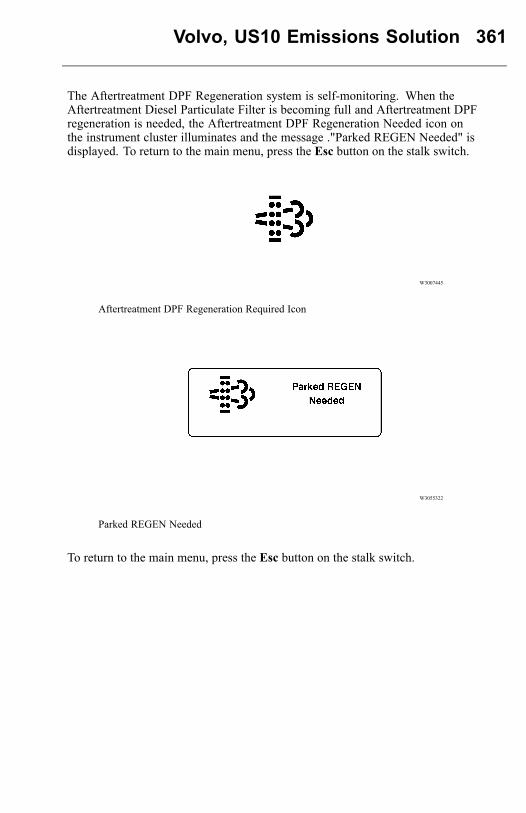
Volvo, US10 Emissions Solution 361
The Aftertreatment DPF Regeneration system is self-monitoring. When theAftertreatment Diesel Particulate Filter is becoming full and Aftertreatment DPFregeneration is needed, the Aftertreatment DPF Regeneration Needed icon onthe instrument cluster illuminates and the message ."Parked REGEN Needed" isdisplayed. To return to the main menu, press the Esc button on the stalk switch.
W3007445
Aftertreatment DPF Regeneration Required Icon
W3055322
Parked REGEN Needed
To return to the main menu, press the Esc button on the stalk switch.
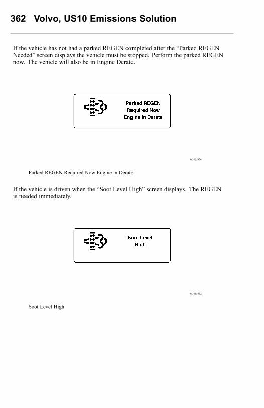
362 Volvo, US10 Emissions Solution
If the vehicle has not had a parked REGEN completed after the “Parked REGENNeeded” screen displays the vehicle must be stopped. Perform the parked REGENnow. The vehicle will also be in Engine Derate.
W3055326
Parked REGEN Required Now Engine in Derate
If the vehicle is driven when the “Soot Level High” screen displays. The REGENis needed immediately.
W3055332
Soot Level High
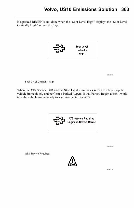
Volvo, US10 Emissions Solution 363
If a parked REGEN is not done when the” Soot Level High” displays the “Soot LevelCritically High” screen displays.
W3055333
Soot Level Critically High
When the ATS Service DID and the Stop Light illuminates screen displays stop thevehicle immediately and perform a Parked Regen. If that Parked Regen doesn’t worktake the vehicle immediately to a service center for ATS.
W3055405
ATS Service Required
W3005171
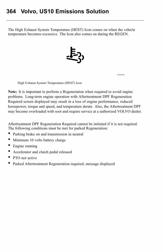
364 Volvo, US10 Emissions Solution
The High Exhaust System Temperature (HEST) Icon comes on when the vehicletemperature becomes excessive. The Icon also comes on during the REGEN.
W3007444
High Exhaust System Temperature (HEST) Icon
Note: It is important to perform a Regeneration when required to avoid engineproblems. Long-term engine operation with Aftertreatment DPF RegenerationRequired screen displayed may result in a loss of engine performance, reducedhorsepower, torque and speed, and temperature derate. Also, the Aftertreatment DPFmay become overloaded with soot and require service at a authorized VOLVO dealer.
Aftertreatment DPF Regeneration Required cannot be initiated if it is not required.The following conditions must be met for parked Regeneration:• Parking brake on and transmission in neutral• Minimum 10 volts battery charge• Engine running• Accelerator and clutch pedal released• PTO not active• Parked Aftertreatment Regeneration required, message displayed
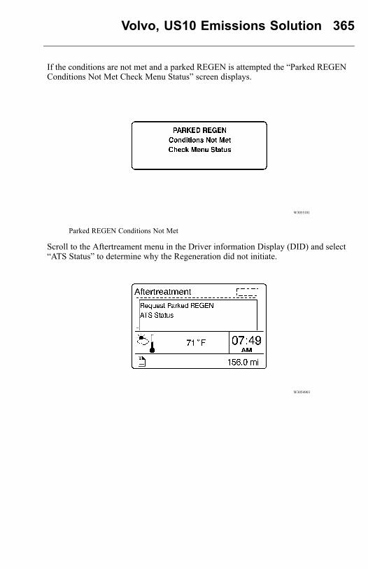
Volvo, US10 Emissions Solution 365
If the conditions are not met and a parked REGEN is attempted the “Parked REGENConditions Not Met Check Menu Status” screen displays.
W3055181
Parked REGEN Conditions Not Met
Scroll to the Aftertreament menu in the Driver information Display (DID) and select“ATS Status” to determine why the Regeneration did not initiate.
W3054903
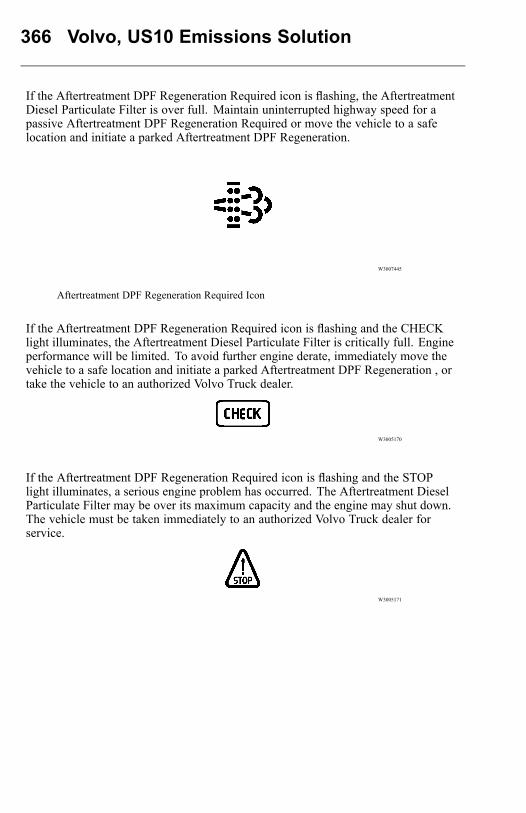
366 Volvo, US10 Emissions Solution
If the Aftertreatment DPF Regeneration Required icon is flashing, the AftertreatmentDiesel Particulate Filter is over full. Maintain uninterrupted highway speed for apassive Aftertreatment DPF Regeneration Required or move the vehicle to a safelocation and initiate a parked Aftertreatment DPF Regeneration.
W3007445
Aftertreatment DPF Regeneration Required Icon
If the Aftertreatment DPF Regeneration Required icon is flashing and the CHECKlight illuminates, the Aftertreatment Diesel Particulate Filter is critically full. Engineperformance will be limited. To avoid further engine derate, immediately move thevehicle to a safe location and initiate a parked Aftertreatment DPF Regeneration , ortake the vehicle to an authorized Volvo Truck dealer.
W3005170
If the Aftertreatment DPF Regeneration Required icon is flashing and the STOPlight illuminates, a serious engine problem has occurred. The Aftertreatment DieselParticulate Filter may be over its maximum capacity and the engine may shut down.The vehicle must be taken immediately to an authorized Volvo Truck dealer forservice.
W3005171
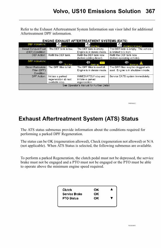
Volvo, US10 Emissions Solution 367
Refer to the Exhaust Aftertreatment System Information sun visor label for additionalAftertreatment DPF information.
W8056652
Exhaust Aftertreatment System (ATS) Status
The ATS status submenus provide information about the conditions required forperforming a parked DPF Regeneration.
The status can be OK (regeneration allowed), Check (regeneration not allowed) or N/A(not applicable). When ATS Status is selected, the following submenus are available.
To perform a parked Regeneration, the clutch pedal must not be depressed, the servicebrake must not be engaged and a PTO must not be engaged or the PTO must be ableto operate above the minimum engine speed required.
W3054893
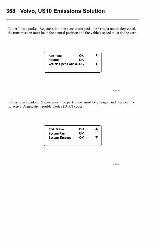
368 Volvo, US10 Emissions Solution
To perform a parked Regeneration, the accelerator pedal (AP) must not be depressed,the transmission must be in the neutral position and the vehicle speed must not be zero.
W3054889
To perform a parked Regeneration, the park brake must be engaged and there can beno active Diagnostic Trouble Codes (DTC) codes.
W3054886
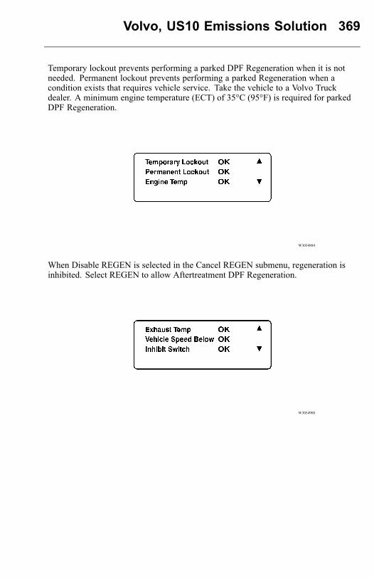
Volvo, US10 Emissions Solution 369
Temporary lockout prevents performing a parked DPF Regeneration when it is notneeded. Permanent lockout prevents performing a parked Regeneration when acondition exists that requires vehicle service. Take the vehicle to a Volvo Truckdealer. A minimum engine temperature (ECT) of 35°C (95°F) is required for parkedDPF Regeneration.
W3054884
When Disable REGEN is selected in the Cancel REGEN submenu, regeneration isinhibited. Select REGEN to allow Aftertreatment DPF Regeneration.
W3054900
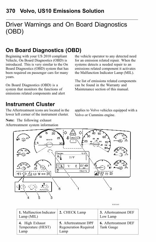
370 Volvo, US10 Emissions Solution
Driver Warnings and On Board Diagnostics(OBD)
On Board Diagnostics (OBD)Beginning with your US 2010 compliantVehicle, On Board Diagnostics (OBD) isintroduced. This is very similar to the OnBoard Diagnostics (OBD) system that hasbeen required on passenger cars for manyyears.
On Board Diagnostics (OBD) is asystem that monitors the functions ofemissions related components and alert
the vehicle operator to any detected needfor an emission related repair. When thesystems detects a needed repair to anemissions related component it activatesthe Malfunction Indicator Lamp (MIL).
The list of emissions related componentscan be found in the Warranty andMaintenance section of this manual.
Instrument ClusterThe Aftertreatment icons are located in thelower left corner of the instrument cluster.Note: The following exhaustAftertreatment system information
applies to Volvo vehicles equipped with aVolvo or Cummins engine.
W3031645
1. Malfunction IndicatorLamp (MIL)
2. CHECK Lamp 3. Aftertreatment DEFLow Lamp
4. High ExhaustTemperature (HEST)Lamp
5. Aftertreatment DPFRegeneration RequiredLamp
6. Aftertreatment DEFTank Gauge
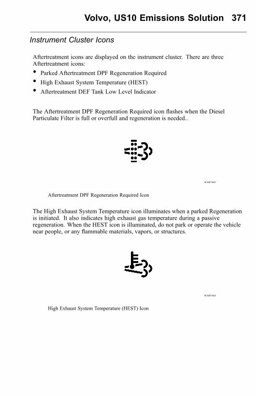
Volvo, US10 Emissions Solution 371
Instrument Cluster Icons
Aftertreatment icons are displayed on the instrument cluster. There are threeAftertreatment icons:• Parked Aftertreatment DPF Regeneration Required• High Exhaust System Temperature (HEST)• Aftertreatment DEF Tank Low Level Indicator
The Aftertreatment DPF Regeneration Required icon flashes when the DieselParticulate Filter is full or overfull and regeneration is needed..
W3007445
Aftertreatment DPF Regeneration Required Icon
The High Exhaust System Temperature icon illuminates when a parked Regenerationis initiated. It also indicates high exhaust gas temperature during a passiveregeneration. When the HEST icon is illuminated, do not park or operate the vehiclenear people, or any flammable materials, vapors, or structures.
W3007444
High Exhaust System Temperature (HEST) Icon
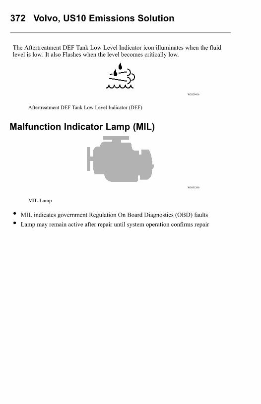
372 Volvo, US10 Emissions Solution
The Aftertreatment DEF Tank Low Level Indicator icon illuminates when the fluidlevel is low. It also Flashes when the level becomes critically low.
W2029416
Aftertreatment DEF Tank Low Level Indicator (DEF)
Malfunction Indicator Lamp (MIL)
W3031200
MIL Lamp
• MIL indicates government Regulation On Board Diagnostics (OBD) faults• Lamp may remain active after repair until system operation confirms repair
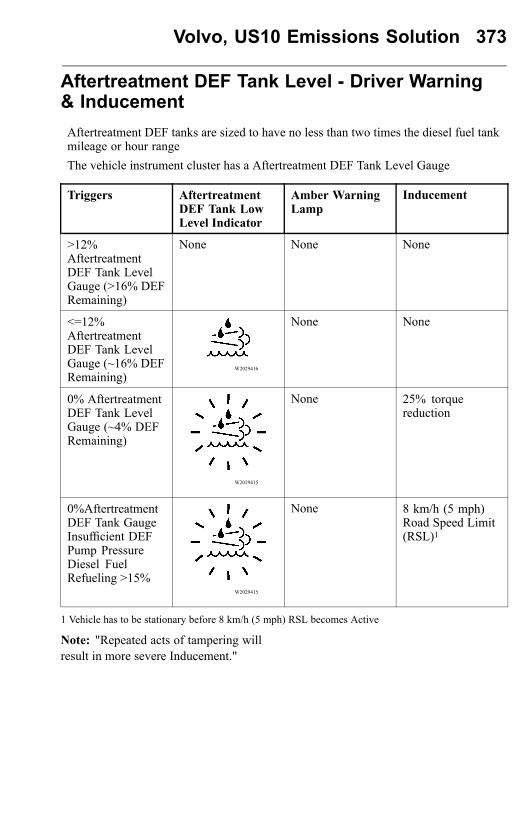
Volvo, US10 Emissions Solution 373
Aftertreatment DEF Tank Level - Driver Warning& InducementAftertreatment DEF tanks are sized to have no less than two times the diesel fuel tankmileage or hour rangeThe vehicle instrument cluster has a Aftertreatment DEF Tank Level Gauge
Triggers AftertreatmentDEF Tank LowLevel Indicator
Amber WarningLamp
Inducement
>12%AftertreatmentDEF Tank LevelGauge (>16% DEFRemaining)
None None None
<=12%AftertreatmentDEF Tank LevelGauge (~16% DEFRemaining)
W2029416
None None
0% AftertreatmentDEF Tank LevelGauge (~4% DEFRemaining)
W2029415
None 25% torquereduction
0%AftertreatmentDEF Tank GaugeInsufficient DEFPump PressureDiesel FuelRefueling >15%
W2029415
None 8 km/h (5 mph)Road Speed Limit(RSL)1
1 Vehicle has to be stationary before 8 km/h (5 mph) RSL becomes Active
Note: "Repeated acts of tampering willresult in more severe Inducement."
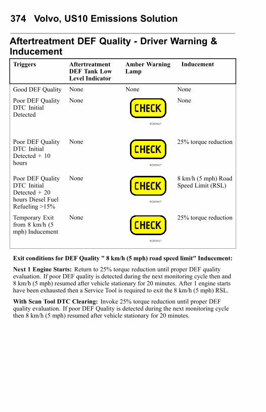
374 Volvo, US10 Emissions Solution
Aftertreatment DEF Quality - Driver Warning &InducementTriggers Aftertreatment
DEF Tank LowLevel Indicator
Amber WarningLamp
Inducement
Good DEF Quality None None None
Poor DEF QualityDTC InitialDetected
None
W2029417
None
Poor DEF QualityDTC InitialDetected + 10hours
None
W2029417
25% torque reduction
Poor DEF QualityDTC InitialDetected + 20hours Diesel FuelRefueling >15%
None
W2029417
8 km/h (5 mph) RoadSpeed Limit (RSL)
Temporary Exitfrom 8 km/h (5mph) Inducement
None
W2029417
25% torque reduction
Exit conditions for DEF Quality " 8 km/h (5 mph) road speed limit" Inducement:
Next 1 Engine Starts: Return to 25% torque reduction until proper DEF qualityevaluation. If poor DEF quality is detected during the next monitoring cycle then and8 km/h (5 mph) resumed after vehicle stationary for 20 minutes. After 1 engine startshave been exhausted then a Service Tool is required to exit the 8 km/h (5 mph) RSL.
With Scan Tool DTC Clearing: Invoke 25% torque reduction until proper DEFquality evaluation. If poor DEF Quality is detected during the next monitoring cyclethen 8 km/h (5 mph) resumed after vehicle stationary for 20 minutes.
Volvo, US10 Emissions Solution 375
Misfilling Diesel or Aftertreatment DEF Tanks
Although diesel fuel and Aftertreatment DEF caps are clearly labeled and filler necksand nozzles are different accidents can happen.
Contamination of fluids by- misfilling of diesel or DEF in the wrong tank may resultin vehicle malfunction.
Results of misfilling DEF in Diesel Tank• Engine may run poorly or not at all• Injectors may be damaged• Exhaust system corrosion may occur between turbocharger and Aftertreatment DPF• On Board Diagnostic (OBD) Diagnostic Trouble Codes (DTC)• Costly repairs
Results of misfilling diesel in Aftertreatment DEF Tank• Aftertreatment SCR system may be damaged by Diesel• SCR Catalyst may be damaged by diesel (chemical damage)• Emissions may be non-compliant• On Board Diagnostic (OBD)Diagnostic Trouble Codes (DTC)• Costly repairs
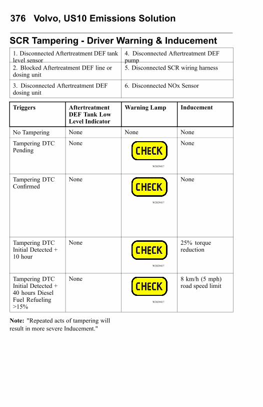
376 Volvo, US10 Emissions Solution
SCR Tampering - Driver Warning & Inducement1. Disconnected Aftertreatment DEF tanklevel sensor
4. Disconnected Aftertreatment DEFpump
2. Blocked Aftertreatment DEF line ordosing unit
5. Disconnected SCR wiring harness
3. Disconnected Aftertreatment DEFdosing unit
6. Disconnected NOx Sensor
Triggers AftertreatmentDEF Tank LowLevel Indicator
Warning Lamp Inducement
No Tampering None None None
Tampering DTCPending
None
W2029417
None
Tampering DTCConfirmed
None
W2029417
None
Tampering DTCInitial Detected +10 hour
None
W2029417
25% torquereduction
Tampering DTCInitial Detected +40 hours DieselFuel Refueling>15%
None
W2029417
8 km/h (5 mph)road speed limit
Note: "Repeated acts of tampering willresult in more severe Inducement."
Volvo, US10 Emissions Solution 377
Warranty and Maintenance
Exhaust Aftertreatment System Maintenance
The vehicle must be taken to an authorized Volvo Truck dealer to remove the ash fromthe Aftertreatment Diesel Particulate Filter and clean the Aftertreatment Doser.
Emissions Maintenance
1. If owner’s manual recommends Aftertreatment DPF replacement within useful life,the manufacturer must pay for the replacement; however, a random failure within theuseful life is covered only per the above warranty provisions.
2. First maintenance interval in life of the engine is allowed at 100,000 miles, 3000hours.

378 Volvo, US10 Emissions Solution
Engine Maintenance Intervals
Component Operation Interval
Fuel Filter Change
Every oil change. Under certainconditions (for example, irregularfuel quality), the fuel/water separatorfilters may require more frequentreplacement.
Air Cleaner Change Control lamp indication or 24months, whichever comes first
Valves/Injectors Lashadjustment,D13H
Initial Adjust 200 000 km (125,000 miles) or 12months, whichever comes first
Injectors Lash Adjustment,D13H Adjust Every 400 000 km (250,000 miles) or
24 months, whichever comes first
Aftertreatment DPF AshCleaning Clean 400 000 km (250,000 miles) or 4,500
hours, whichever occurs first
Aftertreatment Doser Clean 240 000 km (150,000 miles) or 4,500hours, whichever occurs first
Aftertreatment DieselExhaust Fluid (DEF)Pump Filter
Change
First change at 161 000 km (100,000miles) 3200 hours or 3 yearswhichever occurs first, 241,000 km(150,000 miles) 4800 hours or 3years there after
Aftertreatment DieselExhaust Fluid (DEF) FillerNeck Filter
Clean 280 000km (175,000 miles) or 12months, whichever comes first

Volvo, US10 Emissions Solution 379
Engine Gaseous Emission Control Systems
WARRANTY MAINTENANCE
Note: For emission control systems information on engines other than Volvo, refer tothe engine vendor’s publication
GASEOUS EMISSION CONTROL SYSTEMS WARRANTY
Volvo Trucks North America. warrants the Emission Control Systems on each newVolvo diesel engine in a new Volvo truck to comply with all United States Federaland Canadian emissions regulations applicable at the time of manufacture of theengine, and to be free from defects in material and workmanship under normal useand service up to 60 months, or 100,000 miles, whichever occurs first, provided allVolvo Trucks North America, maintenance requirements are followed as describedin this manual. All warranty periods are calculated from the date-in-service of thenew vehicle. The repair or replacement of defective parts will be made without chargefor the cost of parts and, if repairs are made at an authorized Volvo Trucks NorthAmerica dealership, there will be no charge for labor. Volvo Trucks North America’sobligation under this warranty is limited to the repair or replacement, at Volvo TrucksNorth America’s option, of any part(s) of the Emission Control Systems of suchengine and/or vehicle found to be defective upon examination by Volvo Trucks NorthAmerica and provided that such part(s) were returned to Volvo Trucks North Americaor its nearest authorized Dealer within a reasonable period of time.
Qualifications and Limitations:
Note: Not covered by the Emissions Control Systems Warranty:• Malfunctions caused by misuse, improper adjustments, modification, alteration,
tampering, disconnection, improper or inadequate maintenance and use ofimproper diesel fuel or DEF.
• Damage resulting from accident, acts of nature or other events beyond the controlof Volvo Trucks North America.
• Inconvenience, loss of use of the vehicle, commercial loss of any kind including,but not limited to, consequential or incidental damages
• Any vehicle in which the odometer has been altered or damaged so that mileagecannot be readily determined.
THISWARRANTY IS EXPRESSLY IN LIEU OF ALL OTHERWARRANTIESAND REPRESENTATIONS OR CONDITIONS, STATUTORY OROTHERWISE, EXPRESSEDOR IMPLIED INCLUDING, BUT NOT LIMITEDTO, IMPLIED WARRANTY OF MERCHANTABILITY OR FITNESS FOR APARTICULAR PURPOSE.
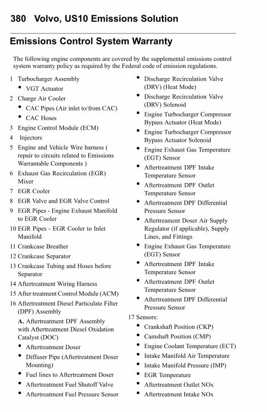
380 Volvo, US10 Emissions Solution
Emissions Control System Warranty
The following engine components are covered by the supplemental emissions controlsystem warranty policy as required by the Federal code of emission regulations.
1 Turbocharger Assembly• VGT Actuator
2 Charge Air Cooler• CAC Pipes (Air inlet to/from CAC)• CAC Hoses
3 Engine Control Module (ECM)4 Injectors5 Engine and Vehicle Wire harness (
repair to circuits related to EmissionsWarrantable Components )
6 Exhaust Gas Recirculation (EGR)Mixer
7 EGR Cooler8 EGR Valve and EGR Valve Control9 EGR Pipes - Engine Exhaust Manifold
to EGR Cooler10 EGR Pipes - EGR Cooler to Inlet
Manifold11 Crankcase Breather12 Crankcase Separator13 Crankcase Tubing and Hoses before
Separator14 Aftertreatment Wiring Harness15 After treatment Control Module (ACM)16 Aftertreatment Diesel Particulate Filter
(DPF) AssemblyA. Aftertreatment DPF Assemblywith Aftertreatment Diesel OxidationCatalyst (DOC)• Aftertreatment Doser• Diffuser Pipe (Aftertreatment Doser
Mounting)• Fuel lines to Aftertreatment Doser• Aftertreatment Fuel Shutoff Valve• Aftertreatment Fuel Pressure Sensor
• Discharge Recirculation Valve(DRV) (Heat Mode)
• Discharge Recirculation Valve(DRV) Solenoid
• Engine Turbocharger CompressorBypass Actuator (Heat Mode)
• Engine Turbocharger CompressorBypass Actuator Solenoid
• Engine Exhaust Gas Temperature(EGT) Sensor
• Aftertreatment DPF IntakeTemperature Sensor
• Aftertreatment DPF OutletTemperature Sensor
• Aftertreatment DPF DifferentialPressure Sensor
• Aftertreament Doser Air SupplyRegulator (if applicable), SupplyLines, and Fittings
• Engine Exhaust Gas Temperature(EGT) Sensor
• Aftertreatment DPF IntakeTemperature Sensor
• Aftertreatment DPF OutletTemperature Sensor
• Aftertreatment DPF DifferentialPressure Sensor
17 Sensors:• Crankshaft Position (CKP)• Camshaft Position (CMP)• Engine Coolant Temperature (ECT)• Intake Manifold Air Temperature• Intake Manifold Pressure (IMP)• EGR Temperature• Aftertreatment Outlet NOx• Aftertreatment Intake NOx

Volvo, US10 Emissions Solution 381
• EGR Differential Pressure• Ambient Air Temperature (AAT)
18 SCR• Aftertreatment Selective Catalytic
Reduction (SCR) Catalyst• Aftertreatment Diesel Exhaust Fluid
(DEF) Pump• Aftertreatment DEF Dosing
Absolute Pressure Sensor• Aftertreatment DEF Return
Valve• Aftertreatment DEF Dosing Valve• Aftertreatment DEF Tank• Aftertreatment DEF Tank
Heater/Sender
• Aftertreatment DEF Tank Heater
• Aftertreatment DEF Tank HeaterValve
• Aftertreatment DEF TankTemperature Sensor
• Aftertreatment DEF Level Sensor
• Aftertreatment DEF Heated Lines
19. Instrument Cluster (Repair ofmicroprocessor , OBD MIL, Real TimeClock, Aftertreatment DEF Tank Gaugeand, Aftertreatment DEF Tank Low LevelIndicator)
20. Exhaust Gas Piping (fromTurbocharger to Aftertreatment System )
21. Data Link Connector (DLC)
Engine Gaseous Emissions Control SystemWarranty
The emission warranty for the diesel particulate filter and SCR Systems covers defectsin workmanship only. Normal maintenance, such as cleaning ash from the filter atregular maintenance intervals and cleaning the Aftertreatment fuel injector on DieselOxidation Catalyst (DOC) DPF systems, is not covered by the emission warranty.With the Thermal Regeneration DPF system, cleaning the ignition electrodes andfuel injection nozzle at the regular maintenance intervals is considered normalmaintenance and not covered by the emission warranty.
Note: In response to customer requests, Volvo Trucks North America, may buildvehicles with engines supplied by other manufacturers. In these cases, each enginemanufacturer through its service organization, is responsible for emission controlsystems warranty on all parts of the engine assembly, as furnished.
Federal Emission Requirements
This section covers the requirement of the United States Clean Air Act which states:“The manufacturer shall furnish with each new motor vehicle or motor vehicle enginesuch written instructions for the maintenance and use of the vehicle or engine bythe ultimate purchaser as may be reasonable and necessary to assure the properfunctioning of emission control devices and systems. ”This section also covers therequirements of the emissions regulations promulgated under the Motor VehicleSafety Act in Canada.
382 Volvo, US10 Emissions Solution
TAMPERING WITH GASEOUS EMISSION CONTROL SYSTEMSPROHIBITED
The Federal Clean Air Act prohibits the removal or rendering inoperative of anydevice or element of design installed on or in a motor vehicle or motor vehicle enginein compliance with Federal Emission Regulations by:1 Any person prior to its sale and delivery to the ultimate purchaser, or2 Any manufacturer or distributor after its sale and delivery to the ultimate purchaser,
or3 Any person engaged in the business of repairing, servicing, selling, leasing, or
trading motor vehicles or motor vehicle engines following its sale and deliveryto the ultimate purchaser, or
4 Any person who operates a fleet of motor vehicles following its sale and deliveryto the ultimate purchaser.
Note: For specifics of the prohibited vehicle/engine modifications refer to the VolvoBody Builders documentation .
Emission Control System Warranty — California
The California Air Resources Board and Volvo Trucks North America. are pleased toexplain the California emission control system warranty on your new motor vehicleengine. In California, new motor vehicle engines must be designed, built and equippedto meet the State’s stringent anti-smog standards. Volvo Trucks North America. mustwarrant the emission control system on your engine for the period of time listed belowprovided there has been no abuse, neglect, or improper maintenance of your engine.Your emission control system may include parts such as the fuel-injection system,turbocharger assembly, electronic control module and other emission-relatedassemblies.
Where a warrantable condition exists, Volvo Trucks North America. will repair yourengine at no cost to you including diagnosis, parts, and labor.MANUFACTURER’S WARRANTY COVERAGE:If an emission-related part of your engine is defective, the part will be repairedor replaced by Volvo Trucks North America. This is your emission control systemDEFECTS WARRANTY.
Volvo, US10 Emissions Solution 383
OWNER’S WARRANTY RESPONSIBILITIES:
As the motor vehicle engine owner, you are responsible for the performance ofthe required maintenance listed in this manual. Volvo Trucks North America.recommends that you retain all receipts covering maintenance of your vehicle, butVolvo Trucks North America. cannot deny warranty solely for the lack of receipts orfor your failure to ensure the performance of all scheduled maintenance listed in othermanuals which were supplied with your vehicle.You are responsible for presenting your motor vehicle engine to a Volvo dealer assoon as a problem exists. The warranty repairs should be completed in a reasonableamount of time, not to exceed 30 days. As the motor vehicle engine owner, you shouldalso be aware that Volvo Trucks North America. may deny you warranty coverageif your vehicle or a part has failed due to abuse, neglect, improper maintenance, orunapproved modifications.If you have any questions regarding your warranty rights and responsibilities, youshould contact the Volvo Trucks North America. Warranty Activities P.O.Box 26259,Greensboro, NC 27402, or the California Air Resources Board at 9480 Telstar Avenue,El Monte, California 91731.(Applicable only to vehicles and/or engines certified for sale and registered in theState of California) Volvo Trucks North America. warrants the Emission ControlSystems on each new Volvo diesel engine in a new Volvo truck to comply with allState of California emissions regulations applicable at the time of manufacture of theengine, and to be free from defects in material and workmanship under normal use andservice up to 60 months, or 100,000 miles, or 3,000 engine operating hours, whicheveroccurs first, provided all Volvo Trucks North America. maintenance requirements arefollowed as described in this manual. All warranty periods are calculated from thedate-in-service of the new vehicle. The repair or replacement of defective parts willbe made without charge for the cost of parts and, if repairs are made at an authorizedVolvo Trucks North America. dealership, there will be no charge for labor.Volvo Trucks North America.’s obligation under this warranty is limited to therepair or replacement, at Volvo Trucks North America.’s option, of any part(s) ofEmission Control Systems of such engine and/or vehicle found to be defective uponexamination by Volvo Trucks North America. and provided that such part(s) werereturned to Volvo Trucks North America. or its nearest authorized Dealer within areasonable period of time.

384 Volvo, US10 Emissions Solution
Qualifications and Limitations:
Not covered by the Emissions Control Systems Warranty:• Malfunctions caused by misuse, improper adjustments, modification, alteration,
tampering, disconnection, improper or inadequate maintenance and use ofimproper diesel fuel or DEF.
• Damage resulting from accident, acts of nature or other events beyond the controlof Volvo Trucks North America.
• Inconvenience, loss of use of the vehicle, commercial loss of any kind including,but not limited to, consequential or incidental damages.
• Any vehicle in which the odometer has been altered or damaged so that mileagecannot be readily determined.
THISWARRANTY IS EXPRESSLY IN LIEU OF ALL OTHERWARRANTIESAND REPRESENTATIONS OR CONDITIONS, STATUTORY OROTHERWISE, EXPRESSEDOR IMPLIED INCLUDING, BUT NOT LIMITEDTO, IMPLIED WARRANTY OF MERCHANTABILITY OR FITNESS FOR APARTICULAR PURPOSE.

Volvo, US10 Emissions Solution 385
Emissions Control System Warranty
The following engine components are covered by the supplemental emissions controlsystem warranty policy as required by the California code of regulations.
1 Turbocharger Assembly
• VGT Actuator
2 Charge Air Cooler
• CAC Pipes (Air inlet to/from CAC)
• CAC Hoses
3 Engine Control Module (ECM)
4 Injectors
5 Engine and Vehicle Wire harness (repair to circuits related to EmissionsWarrantable Components )
6 Exhaust Gas Recirculation (EGR)Mixer
7 EGR Cooler
8 EGR Valve and EGR Valve Control
9 EGR Pipes - Engine Exhaust Manifoldto EGR Cooler
10 EGR Pipes - EGR Cooler to InletManifold
11 Crankcase Breather
12 Crankcase Separator
13 Crankcase Tubing and Hoses beforeSeparator
14 Aftertreatment Wiring Harness
15 After treatment Control Module (ACM)
16 Aftertreatment Diesel Particulate Filter(DPF) Assembly
A. Aftertreatment DPF Assemblywith Aftertreatment Diesel OxidationCatalyst (DOC)
• Aftertreatment Doser
• Diffuser Pipe (Aftertreatment DoserMounting)
• Fuel lines to Aftertreatment Doser
• Aftertreatment Fuel Shutoff Valve
• Aftertreatment Fuel Pressure Sensor
• Discharge Recirculation Valve(DRV) (Heat Mode)
• Discharge Recirculation Valve(DRV) Solenoid
• Engine Turbocharger CompressorBypass Actuator (Heat Mode)
• Engine Turbocharger CompressorBypass Actuator Solenoid
• Engine Exhaust Gas Temperature(EGT) Sensor
• Aftertreatment DPF IntakeTemperature Sensor
• Aftertreatment DPF OutletTemperature Sensor
• Aftertreatment DPF DifferentialPressure Sensor
• Aftertreament Doser Air SupplyRegulator (if applicable), SupplyLines and Fittings
• Engine Exhaust Gas Temperature(EGT) Sensor
• Aftertreatment DPF IntakeTemperature Sensor
• Aftertreatment DPF OutletTemperature Sensor
• Aftertreatment DPF DifferentialPressure Sensor
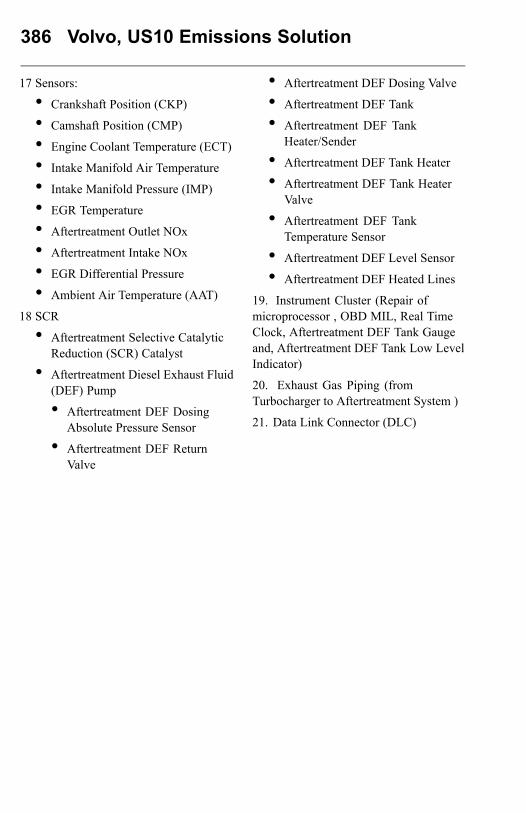
386 Volvo, US10 Emissions Solution
17 Sensors:
• Crankshaft Position (CKP)
• Camshaft Position (CMP)
• Engine Coolant Temperature (ECT)
• Intake Manifold Air Temperature
• Intake Manifold Pressure (IMP)
• EGR Temperature
• Aftertreatment Outlet NOx
• Aftertreatment Intake NOx
• EGR Differential Pressure
• Ambient Air Temperature (AAT)
18 SCR
• Aftertreatment Selective CatalyticReduction (SCR) Catalyst
• Aftertreatment Diesel Exhaust Fluid(DEF) Pump
• Aftertreatment DEF DosingAbsolute Pressure Sensor
• Aftertreatment DEF ReturnValve
• Aftertreatment DEF Dosing Valve
• Aftertreatment DEF Tank
• Aftertreatment DEF TankHeater/Sender
• Aftertreatment DEF Tank Heater
• Aftertreatment DEF Tank HeaterValve
• Aftertreatment DEF TankTemperature Sensor
• Aftertreatment DEF Level Sensor
• Aftertreatment DEF Heated Lines
19. Instrument Cluster (Repair ofmicroprocessor , OBD MIL, Real TimeClock, Aftertreatment DEF Tank Gaugeand, Aftertreatment DEF Tank Low LevelIndicator)
20. Exhaust Gas Piping (fromTurbocharger to Aftertreatment System )
21. Data Link Connector (DLC)
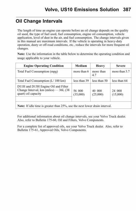
Volvo, US10 Emissions Solution 387
Oil Change Intervals
The length of time an engine can operate before an oil change depends on the qualityoil used, the type of fuel used, fuel consumption, engine oil consumption, vehicleapplication, level of dust in the air, and fuel consumption. The change intervals givenin this manual are maximum intervals. If the vehicle is operating in heavy-dutyoperation, dusty or off-road conditions, etc., reduce the intervals for more frequent oilchanges.
Note: Use the information in the table below to determine the operating condition andusage applicable to your vehicle.
Engine Operating Condition Medium Heavy Severe
Total Fuel Consumption (mpg) more than 6 more than4.7
more than 3.7
Total Fuel Consumption (L/ 100 km) less than 39 less than 50 less than 64
D11H and D13H Engine Oil and FilterChange Interval, km (miles) — 36L (38quart) oil capacity
56 000(35,000)
40 000(25,000)
24 000(15,000)
Note: If idle time is greater than 25%, use the next lower drain interval.
For additional information about oil change intervals, see your Volvo Truck dealer.Also, refer to Bulletin 175-60, Oil and Filters, Volvo Components.
For a complete list of approved oils, see your Volvo Truck dealer. Also, refer toBulletin 175-61, Approved Oils, Volvo Components.

388 MAINTENANCE AND LUBRICATION
DAILY MAINTENANCE
DANGER
Before working on or inspecting avehicle, set the parking brakes, placethe transmission in neutral and blockthe wheels. Failure to do so can result inunexpected vehicle movement and cancause serious personal injury or death.
CAUTION
Engines equipped with automatic startsystems can start automatically. Analarm sounds before automatic start.Failure to turn off ignition beforeworking on fan or belts can result inpersonal injury.
Note: Make sure that all fluid levels are at their proper levels. If the fluids are notat their proper levels, add as necessary. Refer to the Operator’s Manual VehicleMaintenance for information on what types of fluids are recommended for your Volvovehicle.
WARNING
Keep yourself clear of all moving or hotengine parts. A hot engine can causeserious burns.
While checking the fluid levels, visually inspect hoses, pipes and their connections forsigns of leakage. Inspect the ground under the engine, transmission and rear axle(s)for signs of leakage.
MAINTENANCE AND LUBRICATION 389
TOWING PROCEDUREGeneral
WARNING
If a vehicle with air suspension is liftedby the rear frame member, there is arisk that the air springs will separatefrom the spring plates. When towinghas been completed, DO NOT underany circumstances use your hands toreposition the air springs. There is agreat risk that your hand will be caughtbetween spring and plate causingpersonal injury.
WARNING
DO NOT tow a vehicle backwardswhen equipped with roof air fairings.The fairings act as an air scoop andmay break off. Failure to follow thiswarning may lead to personal injuryand vehicle damage.
WARNING
Vehicles with air fairings are tall. Makesure that the total height of the vehicle,when it is raised up behind the wrecker,does not exceed the maximum allowedheight for local underpasses. Failureto follow this instruction may lead topersonal injury and vehicle damage.
CAUTION
Failure to disconnect the driveshaft,remove the drive axle shaft(s) or liftthe drive wheels off the ground beforetowing or pushing the vehicle, cancause serious transmission damage.
Remove the driveshaft from the rear axle before moving the vehicle, unless it onlyneeds to be moved a small distance for safety reasons. When the transmission isdriven from the rear wheels without the engine running, there is no lubrication in thetransmission.Axle shafts must be removed if the vehicle is to be towed at speeds over 40 km/h (25mph) or for a long distance. Openings should be covered to prevent loss of oil andentry of dirt and grit. Where oil-lubricated bearings are used, openings should bethoroughly sealed with metal discs and new gaskets before towing.If the vehicle is towed with the drive wheels still in contact with the road surface, thevehicle axle shafts or driveline must be removed or disconnected.
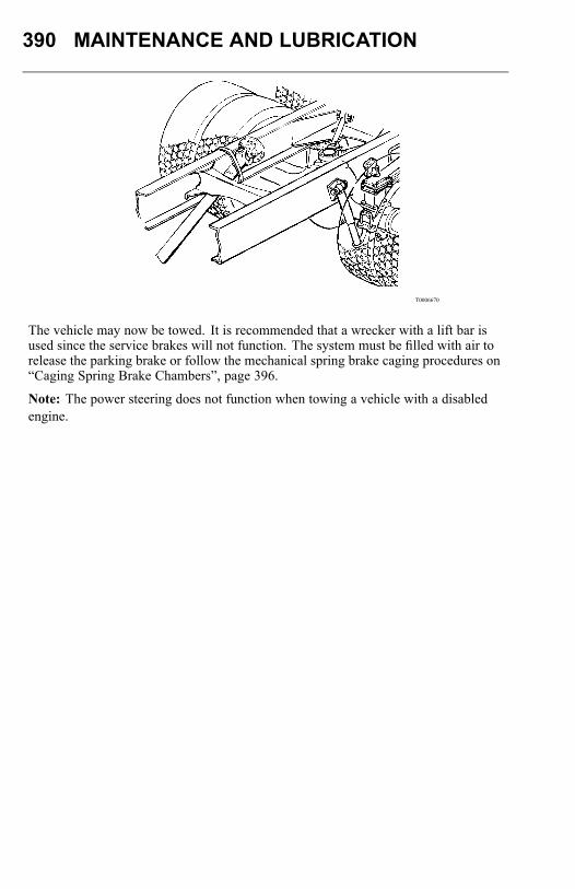
390 MAINTENANCE AND LUBRICATION
T0006670
The vehicle may now be towed. It is recommended that a wrecker with a lift bar isused since the service brakes will not function. The system must be filled with air torelease the parking brake or follow the mechanical spring brake caging procedures on“Caging Spring Brake Chambers”, page 396.
Note: The power steering does not function when towing a vehicle with a disabledengine.
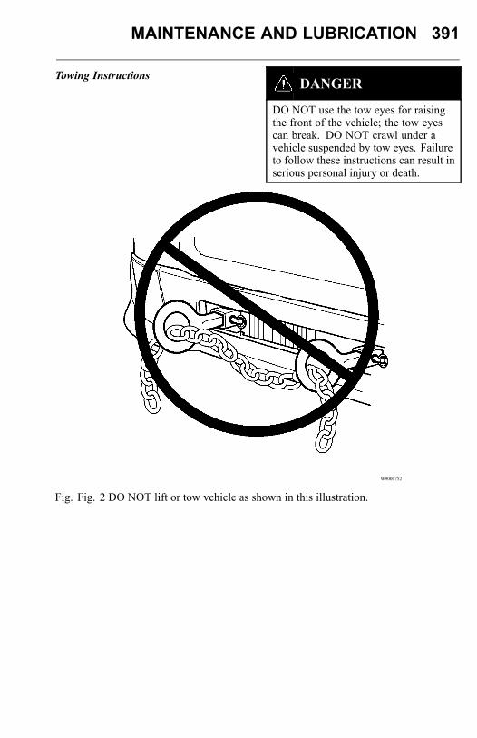
MAINTENANCE AND LUBRICATION 391
Towing InstructionsDANGER
DO NOT use the tow eyes for raisingthe front of the vehicle; the tow eyescan break. DO NOT crawl under avehicle suspended by tow eyes. Failureto follow these instructions can result inserious personal injury or death.
W9000752
Fig. Fig. 2 DO NOT lift or tow vehicle as shown in this illustration.

392 MAINTENANCE AND LUBRICATION
CAUTION
If the vehicle becomes disabled, itis very important to tow it properly.Failure to do so can cause damage tothe frame and body parts. Follow theinstructions below to avoid damage.
In the event that the vehicle cannot be reached to place the wrecker lift bar under thefront axle, use the optional tow eyes. The front tow eyes are used as a point at thefront of the vehicle where the vehicle can be pulled.On day cab models, the tow eyes are stored bolted to the back of the cab wall.On sleeper cab models, the tow eyes are stored bolted to the back wall of the luggagecompartment wall.
W8003124
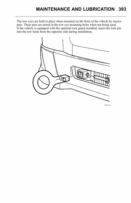
MAINTENANCE AND LUBRICATION 393
The tow eyes are held in place when mounted on the front of the vehicle by tractorpins. These pins are stored in the tow eye mounting holes when not being used.If the vehicle is equipped with the optional rock guard installed, insert the lock pininto the tow hook from the opposite side during installation.
W8003186
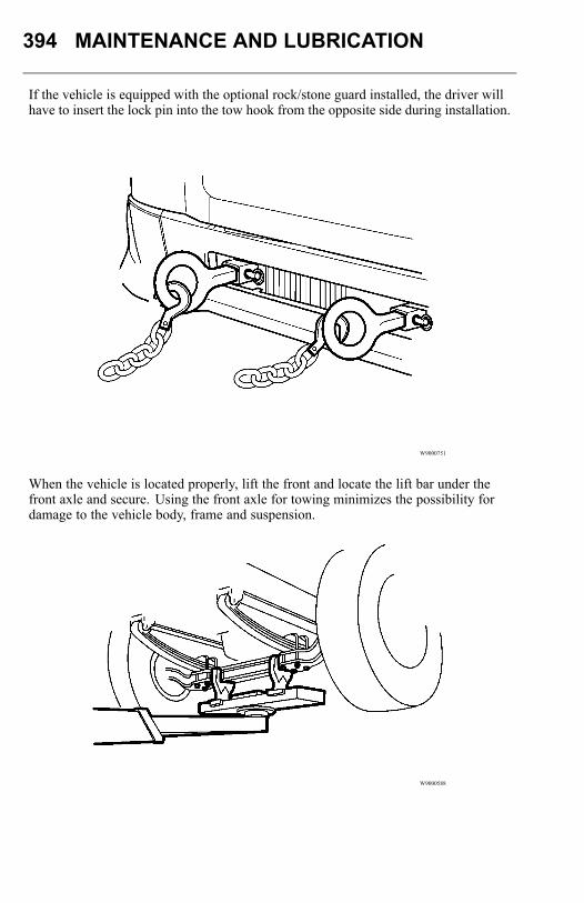
394 MAINTENANCE AND LUBRICATION
If the vehicle is equipped with the optional rock/stone guard installed, the driver willhave to insert the lock pin into the tow hook from the opposite side during installation.
W9000751
When the vehicle is located properly, lift the front and locate the lift bar under thefront axle and secure. Using the front axle for towing minimizes the possibility fordamage to the vehicle body, frame and suspension.
W9000588
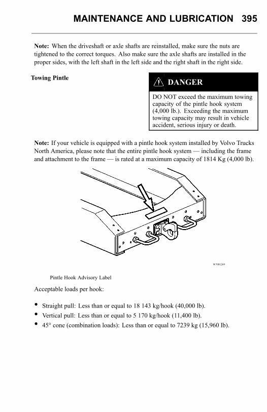
MAINTENANCE AND LUBRICATION 395
Note: When the driveshaft or axle shafts are reinstalled, make sure the nuts aretightened to the correct torques. Also make sure the axle shafts are installed in theproper sides, with the left shaft in the left side and the right shaft in the right side.
Towing Pintle DANGER
DO NOT exceed the maximum towingcapacity of the pintle hook system(4,000 lb.). Exceeding the maximumtowing capacity may result in vehicleaccident, serious injury or death.
Note: If your vehicle is equipped with a pintle hook system installed by Volvo TrucksNorth America, please note that the entire pintle hook system — including the frameand attachment to the frame — is rated at a maximum capacity of 1814 Kg (4,000 lb).
W7001269
Pintle Hook Advisory Label
Acceptable loads per hook:
• Straight pull: Less than or equal to 18 143 kg/hook (40,000 lb).• Vertical pull: Less than or equal to 5 170 kg/hook (11,400 lb).• 45° cone (combination loads): Less than or equal to 7239 kg (15,960 lb).
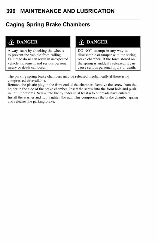
396 MAINTENANCE AND LUBRICATION
Caging Spring Brake Chambers
DANGER
Always start by chocking the wheelsto prevent the vehicle from rolling.Failure to do so can result in unexpectedvehicle movement and serious personalinjury or death can occur.
DANGER
DO NOT attempt in any way todisassemble or tamper with the springbrake chamber. If the force stored onthe spring is suddenly released, it cancause serious personal injury or death.
The parking spring brake chambers may be released mechanically if there is nocompressed air available.Remove the plastic plug in the front end of the chamber. Remove the screw from theholder in the side of the brake chamber. Insert the screw into the front hole and pushin until it bottoms. Screw into the cylinder so at least 4 to 6 threads have entered.Install the washer and nut. Tighten the nut. This compresses the brake chamber springand releases the parking brake.
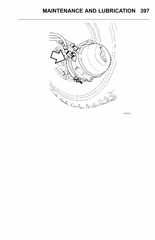
MAINTENANCE AND LUBRICATION 397
W5001430
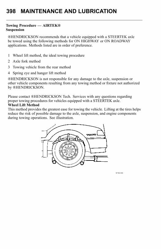
398 MAINTENANCE AND LUBRICATION
Towing Procedure — AIRTEK®Suspension
®HENDRICKSON recommends that a vehicle equipped with a STEERTEK axlebe towed using the following methods for ON HIGHWAY or ON ROADWAYapplications. Methods listed are in order of preference.
1 Wheel lift method, the ideal towing procedure2 Axle fork method3 Towing vehicle from the rear method4 Spring eye and hanger lift method®HENDRICKSON is not responsible for any damage to the axle, suspension orother vehicle components resulting from any towing method or fixture not authorizedby ®HENDRICKSON.
Please contact ®HENDRICKSON Tech. Services with any questions regardingproper towing procedures for vehicles equipped with a STEERTEK axle.Wheel Lift MethodThis method provides the greatest ease for towing the vehicle. Lifting at the tires helpsreduce the risk of possible damage to the axle, suspension, and engine componentsduring towing operations. See illustration.
W7001300
MAINTENANCE AND LUBRICATION 399
CAUTION
DO NOT tow the vehicle from the axle.Towing the vehicle by the axle willcause scarring and resultant damage tothe axle and void warranty.
When lifting a vehicle with an under lift boom, care must be taken not to damage theengine’s oil pan. It may also be necessary to remove the front fairing.This is an alternative method for towing the vehicle, but it requires SPECIAL forks(see illustration showing designated lift points). The following procedure must beused:
• Place a block of wood on top of the boom and lift the vehicle in order to placespacers under tires. This will provide sufficient room under the axle to locate forksin the proper position.
• Install the fork in the boom properly with the angled arm of the fork facing forward.• Position the forks directly under the center of the bottom axle wraps, and lift
vehicle. The indentions in the center of the wrap will locate the forks and maintaintheir position.
• When securing the vehicle to the boom, use (preferably) nylon safety straps.Chains have a tendency to bind and may cause damage to the axle.
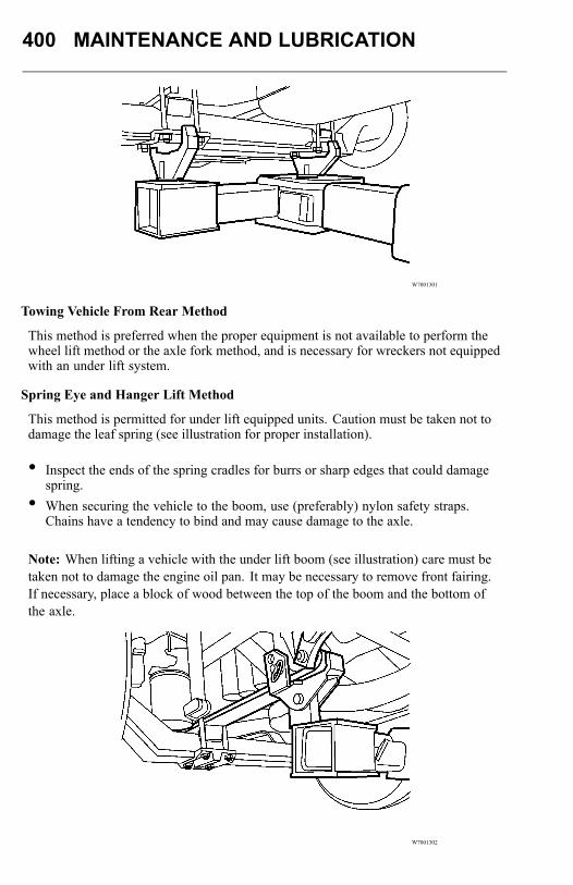
400 MAINTENANCE AND LUBRICATION
W7001301
Towing Vehicle From Rear Method
This method is preferred when the proper equipment is not available to perform thewheel lift method or the axle fork method, and is necessary for wreckers not equippedwith an under lift system.
Spring Eye and Hanger Lift Method
This method is permitted for under lift equipped units. Caution must be taken not todamage the leaf spring (see illustration for proper installation).
• Inspect the ends of the spring cradles for burrs or sharp edges that could damagespring.
• When securing the vehicle to the boom, use (preferably) nylon safety straps.Chains have a tendency to bind and may cause damage to the axle.
Note: When lifting a vehicle with the under lift boom (see illustration) care must betaken not to damage the engine oil pan. It may be necessary to remove front fairing.If necessary, place a block of wood between the top of the boom and the bottom ofthe axle.
W7001302

MAINTENANCE AND LUBRICATION 401
Off Roadway Towing Method
WARNING
When a truck is disabled and equippedwith a STEERTEK axle, care must betaken to ensure there is no damage tothe suspension when towing the vehicle.The use of a tow strap is necessaryto tow a disabled truck into a repairfacility. The tow straps should beconnected to the tow hooks providedby the manufacturer at the front of thebumper. If the use of tow hooks isnot an option, then a tow strap maybe wrapped around the front axle(see illustration) in a manner that isacceptable for towing the vehicle intothe shop.DO NOT use a tow chain around thefront axle to tow the vehicle. Doing sowill damage the axle and void warranty.See illustration.
THE FOLLOWING METHODS IN THESE ILLUSTRATIONS ARE NOTRECOMMENDED FOR ON HIGHWAY TOWING
W7001303
Nylon straps are acceptable for only Off roadway towing.
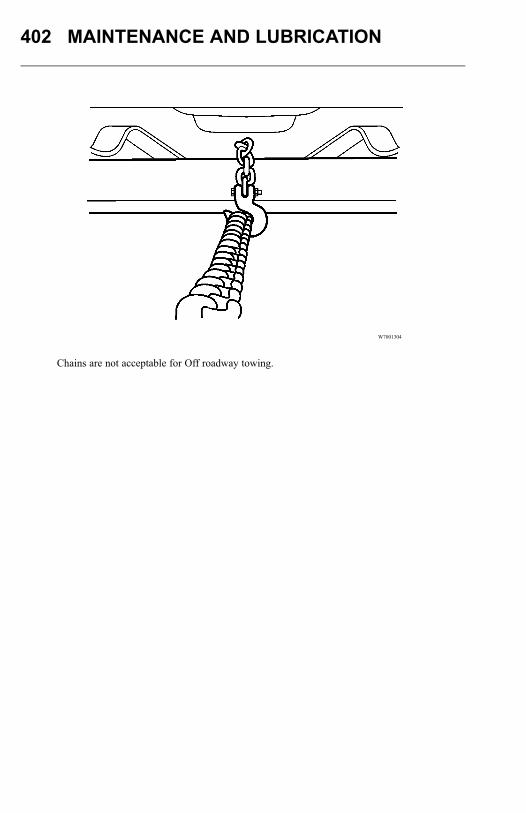
402 MAINTENANCE AND LUBRICATION
W7001304
Chains are not acceptable for Off roadway towing.
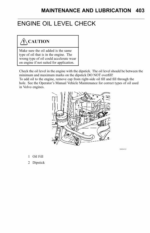
MAINTENANCE AND LUBRICATION 403
ENGINE OIL LEVEL CHECK
CAUTION
Make sure the oil added is the sametype of oil that is in the engine. Thewrong type of oil could accelerate wearon engine if not suited for application.
Check the oil level in the engine with the dipstick. The oil level should be between theminimum and maximum marks on the dipstick DO NOT overfill!To add oil to the engine, remove cap from right-side oil fill and fill through thehole. See the Operator’s Manual Vehicle Maintenance for correct types of oil usedin Volvo engines.
W0056532
1 Oil Fill
2 Dipstick

404 MAINTENANCE AND LUBRICATION
Clutch Fluid Check
Check the fluid level in the clutch fluid reservoir. The fluid level should be betweenthe level marks on the reservoir. If fluid needs to be added, use brake fluid, DOT 4.
W4056530
1 Clutch Fluid Reservoir
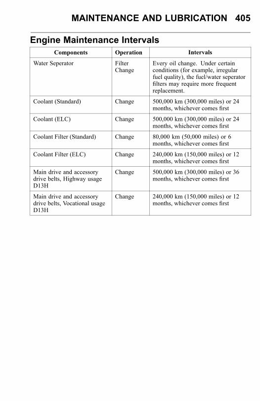
MAINTENANCE AND LUBRICATION 405
Engine Maintenance IntervalsComponents Operation Intervals
Water Seperator FilterChange
Every oil change. Under certainconditions (for example, irregularfuel quality), the fuel/water seperatorfilters may require more frequentreplacement.
Coolant (Standard) Change 500,000 km (300,000 miles) or 24months, whichever comes first
Coolant (ELC) Change 500,000 km (300,000 miles) or 24months, whichever comes first
Coolant Filter (Standard) Change 80,000 km (50,000 miles) or 6months, whichever comes first
Coolant Filter (ELC) Change 240,000 km (150,000 miles) or 12months, whichever comes first
Main drive and accessorydrive belts, Highway usageD13H
Change 500,000 km (300,000 miles) or 36months, whichever comes first
Main drive and accessorydrive belts, Vocational usageD13H
Change 240,000 km (150,000 miles) or 12months, whichever comes first
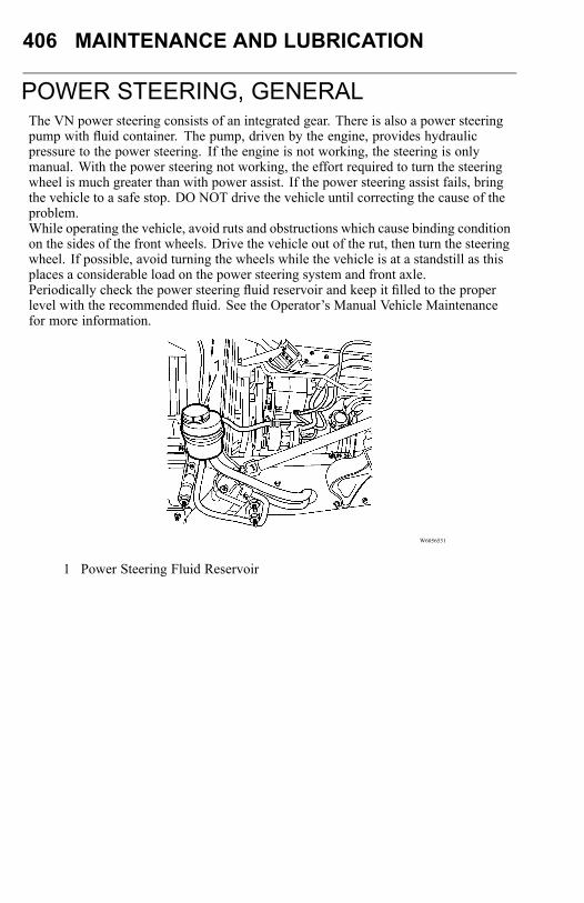
406 MAINTENANCE AND LUBRICATION
POWER STEERING, GENERALThe VN power steering consists of an integrated gear. There is also a power steeringpump with fluid container. The pump, driven by the engine, provides hydraulicpressure to the power steering. If the engine is not working, the steering is onlymanual. With the power steering not working, the effort required to turn the steeringwheel is much greater than with power assist. If the power steering assist fails, bringthe vehicle to a safe stop. DO NOT drive the vehicle until correcting the cause of theproblem.While operating the vehicle, avoid ruts and obstructions which cause binding conditionon the sides of the front wheels. Drive the vehicle out of the rut, then turn the steeringwheel. If possible, avoid turning the wheels while the vehicle is at a standstill as thisplaces a considerable load on the power steering system and front axle.Periodically check the power steering fluid reservoir and keep it filled to the properlevel with the recommended fluid. See the Operator’s Manual Vehicle Maintenancefor more information.
W6056531
1 Power Steering Fluid Reservoir
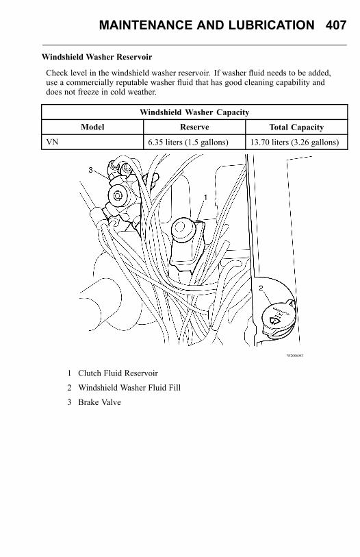
MAINTENANCE AND LUBRICATION 407
Windshield Washer Reservoir
Check level in the windshield washer reservoir. If washer fluid needs to be added,use a commercially reputable washer fluid that has good cleaning capability anddoes not freeze in cold weather.
Windshield Washer Capacity
Model Reserve Total Capacity
VN 6.35 liters (1.5 gallons) 13.70 liters (3.26 gallons)
W2006043
1 Clutch Fluid Reservoir
2 Windshield Washer Fluid Fill
3 Brake Valve
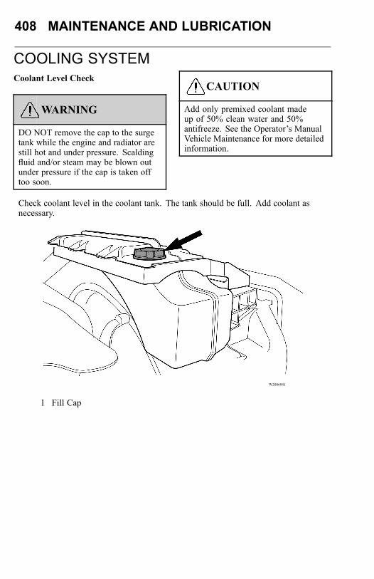
408 MAINTENANCE AND LUBRICATION
COOLING SYSTEMCoolant Level Check
WARNING
DO NOT remove the cap to the surgetank while the engine and radiator arestill hot and under pressure. Scaldingfluid and/or steam may be blown outunder pressure if the cap is taken offtoo soon.
CAUTION
Add only premixed coolant madeup of 50% clean water and 50%antifreeze. See the Operator’s ManualVehicle Maintenance for more detailedinformation.
Check coolant level in the coolant tank. The tank should be full. Add coolant asnecessary.
W2006041
1 Fill Cap
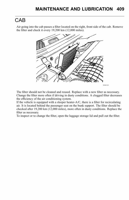
MAINTENANCE AND LUBRICATION 409
CABAir going into the cab passes a filter located on the right, front side of the cab. Removethe filter and check it every 19,200 km (12,000 miles).
W8003189
The filter should not be cleaned and reused. Replace with a new filter as necessary.Change the filter more often if driving in dusty conditions. A clogged filter decreasesthe efficiency of the air conditioning system.If the vehicle is equipped with a sleeper heater-A/C, there is a filter for recirculatingair. It is located behind the passenger seat on the bunk support. The filter should bechecked after 19,200 km (12,000 miles), more often in dusty conditions. Replace thefilter as necessary.To inspect or to change the filter, open the luggage storage lid and pull out the filter.
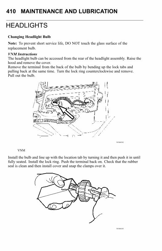
410 MAINTENANCE AND LUBRICATION
HEADLIGHTSChanging Headlight Bulb
Note: To prevent short service life, DO NOT touch the glass surface of thereplacement bulb.VNM InstructionsThe headlight bulb can be accessed from the rear of the headlight assembly. Raise thehood and remove the cover.Remove the terminal from the back of the bulb by bending up the lock tabs andpulling back at the same time. Turn the lock ring counterclockwise and remove.Pull out the bulb.
W3004382
VNM
Install the bulb and line up with the location tab by turning it and then push it in untilfully seated. Install the lock ring. Push the terminal back on. Check that the rubberseal is clean and then install cover and snap the clamps over it.
W3004383

MAINTENANCE AND LUBRICATION 411
VNL Instructions
The headlight bulb can be accessed from the rear of the headlight assembly. Raise thehood. In early production vehicles, remove the bulb cover by turning clockwise.In later production vehicles, the cover can be removed in the normal counterclockwisedirection.
Note: In some cases, the cover seal may stick to the housing, which makes removaldifficult. Use special tool 85104355 to assist in removal. Contact your authorizedVolvo dealer for the tool.
With the cover removed, grasp the bulb assembly and turn counterclockwise toremove. Disengage the wiring connector and remove the bulb from the vehicle.Engage the wiring harness connector to the replacement bulb assembly. Install intothe headlamp housing. Check the bulb cover seal and install the bulb cover. Lowerthe hood and check for proper headlamp operation.
W3005350
1 Low Beam Headlight (Cover Installed)
2 High Beam Headlight (Cover Removed)
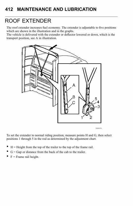
412 MAINTENANCE AND LUBRICATION
ROOF EXTENDERThe roof extender increases fuel economy. The extender is adjustable to five positionswhich are shown in the illustration and in the graphs.The vehicle is delivered with the extender or deflector lowered or down, which is thetransport position, see A in illustration.
W8003470
To set the extender to normal riding position, measure points H and G, then selectpositions 1 through 5 in the rod as determined by the adjustment chart.
• H = Height from the top of the trailer to the top of the frame rail.• G = Gap or distance from the back of the cab to the trailer.• F = Frame rail height.
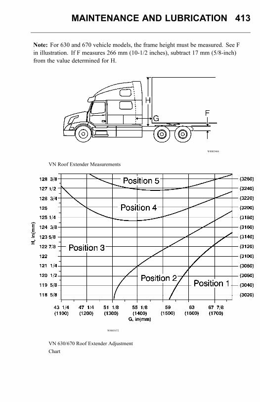
MAINTENANCE AND LUBRICATION 413
Note: For 630 and 670 vehicle models, the frame height must be measured. See Fin illustration. If F measures 266 mm (10-1/2 inches), subtract 17 mm (5/8-inch)from the value determined for H.
W8003466
VN Roof Extender Measurements
W8003472
VN 630/670 Roof Extender AdjustmentChart

414 MAINTENANCE AND LUBRICATION
W8003473
VN 630/670 Roof Extender AdjustmentChart

MAINTENANCE AND LUBRICATION 415
FRONT BUMPER/LICENSE PLATEMOUNTING
CAUTION
DO NOT cover the opening in the frontbumper with a license plate. Coveringthis hole will restrict airflow to thelower portion of the radiator. This cancause the engine to overheat, which candamage the engine.
When placing the license plate on the vehicle, make sure the opening in the bumper isnot covered.
W8003518
VN
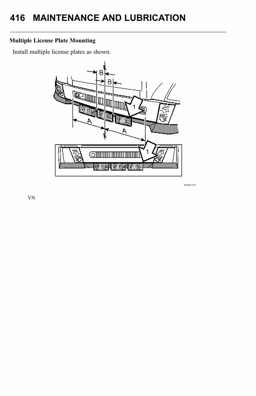
416 MAINTENANCE AND LUBRICATION
Multiple License Plate Mounting
Install multiple license plates as shown.
W8003370
VN
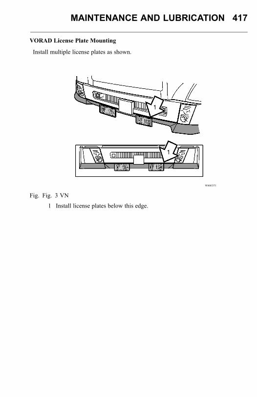
MAINTENANCE AND LUBRICATION 417
VORAD License Plate Mounting
Install multiple license plates as shown.
W8003371
Fig. Fig. 3 VN
1 Install license plates below this edge.

418 MAINTENANCE AND LUBRICATION
MODIFICATIONS TO VEHICLEChassis Frame
WARNING
DO NOT weld on any part of the frameor drill holes in the top or bottomflanges. Serious structural damagecould occur.
Frame side rails are heat treated. No welding is permitted because this can result instructural failure. DO NOT drill through either top or bottom flanges. A warning labelis also attached to the frame for information.
W7001277
Drilling is permitted in the frame web in accordance with a specified hole spacingpattern. Consult an authorized Volvo Truck dealer to obtain approved hole spacingdimensions or refer to the Frame Rail and Cross Member Service Manual.
MAINTENANCE AND LUBRICATION 419
Frame rail and cross member nuts and bolts should be checked periodically andtightened to the specified torque if necessary.Frame AlterationsUnder no circumstances can the frame be cut and an extension piece added to increasethe wheelbase. The only alteration allowed is wheel base shortening, where the onlychange in the frame rail is a new hole pattern drilled for the new location of the rearsuspension.Welding in Vehicle
CAUTION
Use only electric welders due to thecoating on material used to build cabs.Oxygen and Acetylene welding will notbond properly due to coating.
Do not weld anywhere in or on the vehicle before disconnecting batteries, allelectronic control units (ECUs) and instrument cluster.DO NOT use oxy/acetylene welding to repair cab panels.
420 MAINTENANCE AND LUBRICATION
WHEELSGeneralDue to the size, equipment needed and the procedures used to change wheels, thisshould be done through the Volvo Truck dealer. By having an expert technicianperform this procedure, personal injury and property damage may be avoided.
Note: When replacing the wheel equipment or tires, use the same size wheels ortires as originally manufactured. Changing the tire or wheel size will affect brakeperformance. If changing tire size, ABS and speedometer must be recalibrated.
Check Wheel Nuts Torque
DANGER
Failure to properly tighten the wheelnuts can result in the breakage of wheelstuds and the subsequent loss of wheels.Loss of vehicle control and seriouspersonal injury or death can occur.
Check all wheel nuts torque after the first 80 to 160 km (50 to 100 miles) and the first80 to 160 km (50 to 100 miles) after each tire service. This applies to both single anddual wheels in connection with normal service but should be performed at least everysix months.The torque check is particularly important when rims or brake drums are newlypainted. Paint can flake off from these surfaces, causing the nuts to lose their grip andthe wheel to loosen.See the Operator’s Manual Vehicle Maintenance for correct procedures on tighteningthe wheel nuts.
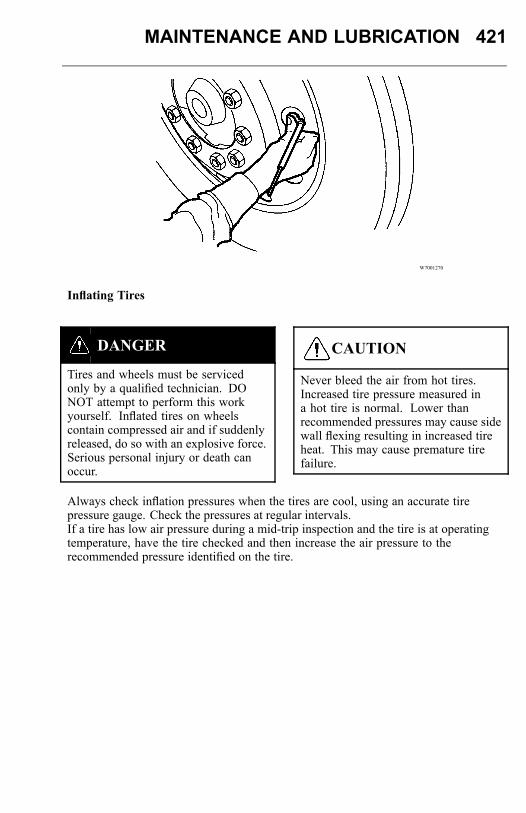
MAINTENANCE AND LUBRICATION 421
W7001270
Inflating Tires
DANGER
Tires and wheels must be servicedonly by a qualified technician. DONOT attempt to perform this workyourself. Inflated tires on wheelscontain compressed air and if suddenlyreleased, do so with an explosive force.Serious personal injury or death canoccur.
CAUTION
Never bleed the air from hot tires.Increased tire pressure measured ina hot tire is normal. Lower thanrecommended pressures may cause sidewall flexing resulting in increased tireheat. This may cause premature tirefailure.
Always check inflation pressures when the tires are cool, using an accurate tirepressure gauge. Check the pressures at regular intervals.If a tire has low air pressure during a mid-trip inspection and the tire is at operatingtemperature, have the tire checked and then increase the air pressure to therecommended pressure identified on the tire.
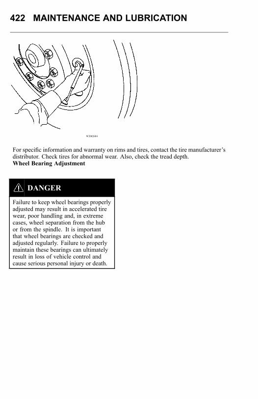
422 MAINTENANCE AND LUBRICATION
W2002684
For specific information and warranty on rims and tires, contact the tire manufacturer’sdistributor. Check tires for abnormal wear. Also, check the tread depth.Wheel Bearing Adjustment
DANGER
Failure to keep wheel bearings properlyadjusted may result in accelerated tirewear, poor handling and, in extremecases, wheel separation from the hubor from the spindle. It is importantthat wheel bearings are checked andadjusted regularly. Failure to properlymaintain these bearings can ultimatelyresult in loss of vehicle control andcause serious personal injury or death.
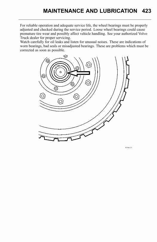
MAINTENANCE AND LUBRICATION 423
For reliable operation and adequate service life, the wheel bearings must be properlyadjusted and checked during the service period. Loose wheel bearings could causepremature tire wear and possibly affect vehicle handling. See your authorized VolvoTruck dealer for proper servicing.Watch carefully for oil leaks and listen for unusual noises. These are indications ofworn bearings, bad seals or misadjusted bearings. These are problems which must becorrected as soon as possible.
W7001271
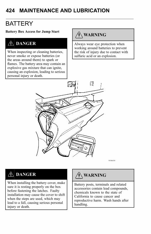
424 MAINTENANCE AND LUBRICATION
BATTERYBattery Box Access for Jump Start
DANGER
When inspecting or cleaning batteries,never smoke or expose batteries (orthe areas around them) to spark orflames. The battery area may contain anexplosive gas mixture that can ignite,causing an explosion, leading to seriouspersonal injury or death.
WARNING
Always wear eye protection whenworking around batteries to preventthe risk of injury due to contact withsulfuric acid or an explosion.
W3006385
DANGER
When installing the battery cover, makesure it is resting properly on the boxbefore fastening the latches. Faultyinstallation may cause the cover to shiftwhen the steps are used, which maylead to a fall, causing serious personalinjury or death.
WARNING
Battery posts, terminals and relatedaccessories contain lead compounds,chemicals known to the state ofCalifornia to cause cancer andreproductive harm. Wash hands afterhandling.
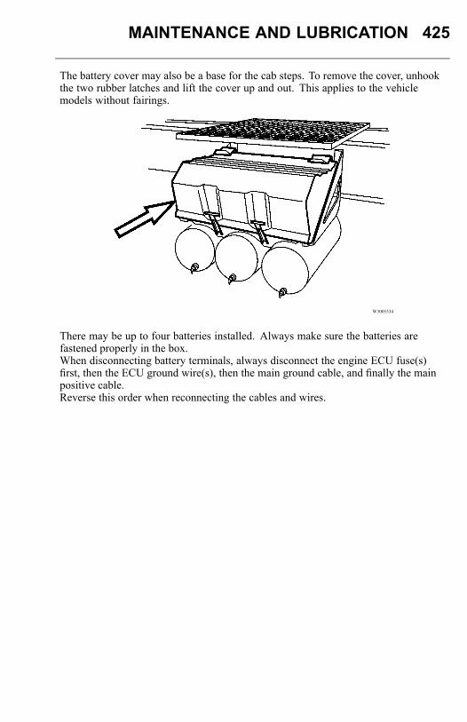
MAINTENANCE AND LUBRICATION 425
The battery cover may also be a base for the cab steps. To remove the cover, unhookthe two rubber latches and lift the cover up and out. This applies to the vehiclemodels without fairings.
W3005334
There may be up to four batteries installed. Always make sure the batteries arefastened properly in the box.When disconnecting battery terminals, always disconnect the engine ECU fuse(s)first, then the ECU ground wire(s), then the main ground cable, and finally the mainpositive cable.Reverse this order when reconnecting the cables and wires.
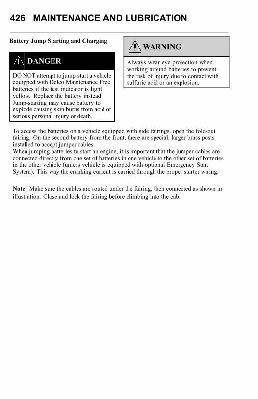
426 MAINTENANCE AND LUBRICATION
Battery Jump Starting and Charging
DANGER
DONOT attempt to jump-start a vehicleequipped with Delco Maintenance Freebatteries if the test indicator is lightyellow. Replace the battery instead.Jump-starting may cause battery toexplode causing skin burns from acid orserious personal injury or death.
WARNING
Always wear eye protection whenworking around batteries to preventthe risk of injury due to contact withsulfuric acid or an explosion.
To access the batteries on a vehicle equipped with side fairings, open the fold-outfairing. On the second battery from the front, there are special, larger brass postsinstalled to accept jumper cables.When jumping batteries to start an engine, it is important that the jumper cables areconnected directly from one set of batteries in one vehicle to the other set of batteriesin the other vehicle (unless vehicle is equipped with optional Emergency StartSystem). This way the cranking current is carried through the proper starter wiring.
Note: Make sure the cables are routed under the fairing, then connected as shown inillustration. Close and lock the fairing before climbing into the cab.
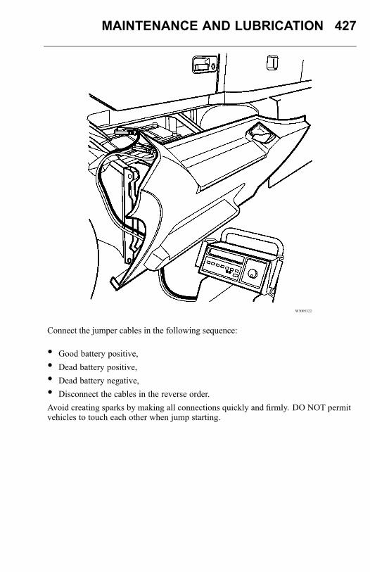
MAINTENANCE AND LUBRICATION 427
W3005322
Connect the jumper cables in the following sequence:
• Good battery positive,• Dead battery positive,• Dead battery negative,• Disconnect the cables in the reverse order.Avoid creating sparks by making all connections quickly and firmly. DO NOT permitvehicles to touch each other when jump starting.
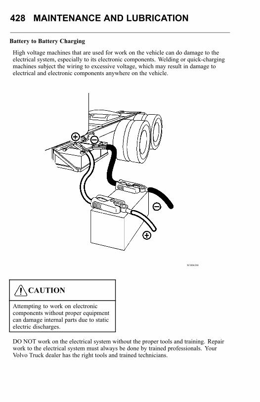
428 MAINTENANCE AND LUBRICATION
Battery to Battery Charging
High voltage machines that are used for work on the vehicle can do damage to theelectrical system, especially to its electronic components. Welding or quick-chargingmachines subject the wiring to excessive voltage, which may result in damage toelectrical and electronic components anywhere on the vehicle.
W3006384
CAUTION
Attempting to work on electroniccomponents without proper equipmentcan damage internal parts due to staticelectric discharges.
DO NOT work on the electrical system without the proper tools and training. Repairwork to the electrical system must always be done by trained professionals. YourVolvo Truck dealer has the right tools and trained technicians.
MAINTENANCE AND LUBRICATION 429
Battery, Low State of Charge
If the batteries are discharged to the point where they do not have enough storedenergy to start the engine, they should be recharged using a low charge current, not toexceed 14.5 to 15.0 volts.If the vehicle needs to be started immediately, use a starting batteries charger.
Note: If the voltage power is exceeded, this can cause damage to the lighting systemand bulbs.
DO NOT use battery chargers with very high "boosting" capability. These producea high voltage that may cause damage to the vehicle electrical and electroniccomponents.Welding
CAUTION
Welding on the vehicle can damage theelectrical system or components dueto the high voltage and current spikesthat normally occur when welding. Itis preferable to avoid welding on anassembled vehicle. However, if anystructure on or in contact with thevehicle must be welded, follow therecommendations below.
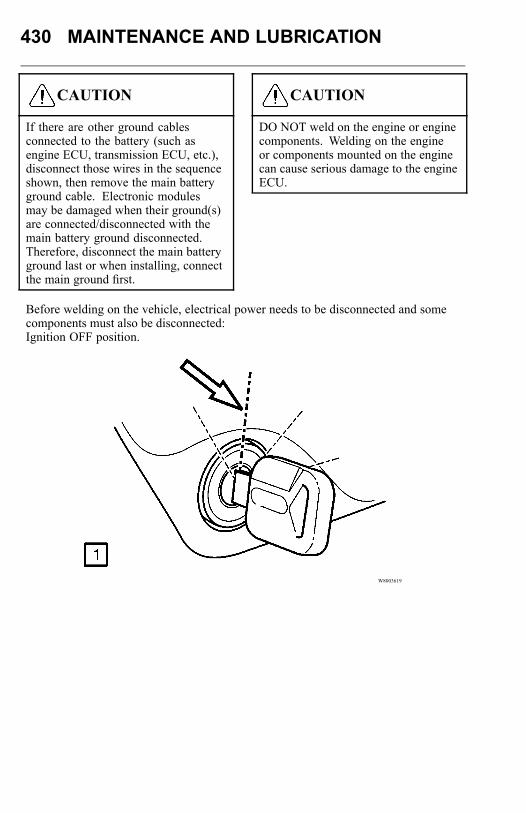
430 MAINTENANCE AND LUBRICATION
CAUTION
If there are other ground cablesconnected to the battery (such asengine ECU, transmission ECU, etc.),disconnect those wires in the sequenceshown, then remove the main batteryground cable. Electronic modulesmay be damaged when their ground(s)are connected/disconnected with themain battery ground disconnected.Therefore, disconnect the main batteryground last or when installing, connectthe main ground first.
CAUTION
DO NOT weld on the engine or enginecomponents. Welding on the engineor components mounted on the enginecan cause serious damage to the engineECU.
Before welding on the vehicle, electrical power needs to be disconnected and somecomponents must also be disconnected:Ignition OFF position.
W8003619
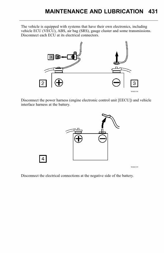
MAINTENANCE AND LUBRICATION 431
The vehicle is equipped with systems that have their own electronics, includingvehicle ECU (VECU), ABS, air bag (SRS), gauge cluster and some transmissions.Disconnect each ECU at its electrical connectors.
W8003198
Disconnect the power harness (engine electronic control unit [EECU]) and vehicleinterface harness at the battery.
W8003199
Disconnect the electrical connections at the negative side of the battery.
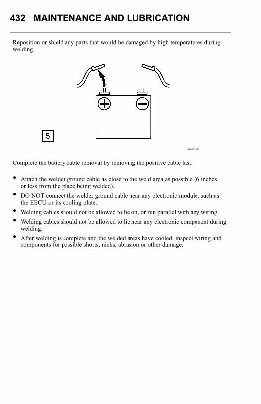
432 MAINTENANCE AND LUBRICATION
Reposition or shield any parts that would be damaged by high temperatures duringwelding.
W8003200
Complete the battery cable removal by removing the positive cable last.
• Attach the welder ground cable as close to the weld area as possible (6 inchesor less from the place being welded).
• DO NOT connect the welder ground cable near any electronic module, such asthe EECU or its cooling plate.
• Welding cables should not be allowed to lie on, or run parallel with any wiring.• Welding cables should not be allowed to lie near any electronic component during
welding.• After welding is complete and the welded areas have cooled, inspect wiring and
components for possible shorts, nicks, abrasion or other damage.
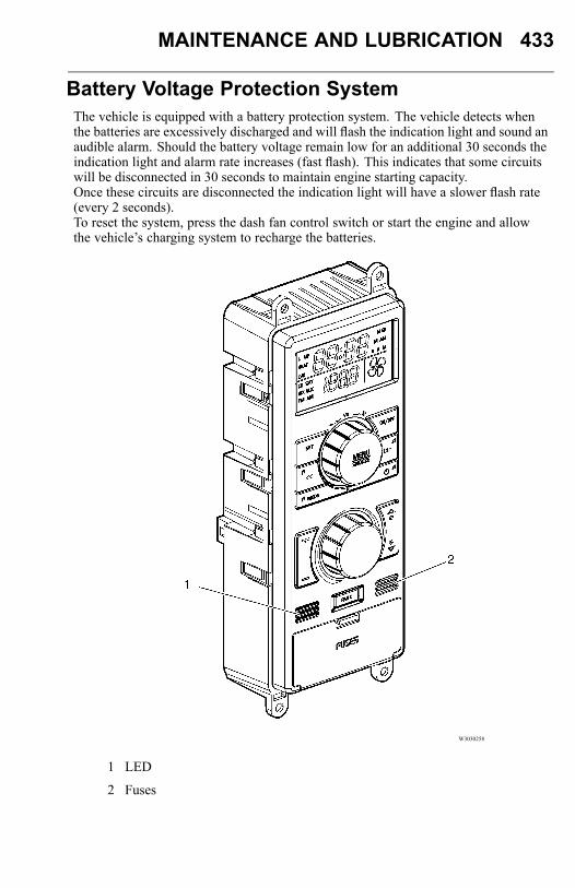
MAINTENANCE AND LUBRICATION 433
Battery Voltage Protection SystemThe vehicle is equipped with a battery protection system. The vehicle detects whenthe batteries are excessively discharged and will flash the indication light and sound anaudible alarm. Should the battery voltage remain low for an additional 30 seconds theindication light and alarm rate increases (fast flash). This indicates that some circuitswill be disconnected in 30 seconds to maintain engine starting capacity.Once these circuits are disconnected the indication light will have a slower flash rate(every 2 seconds).To reset the system, press the dash fan control switch or start the engine and allowthe vehicle’s charging system to recharge the batteries.
W3030258
1 LED
2 Fuses
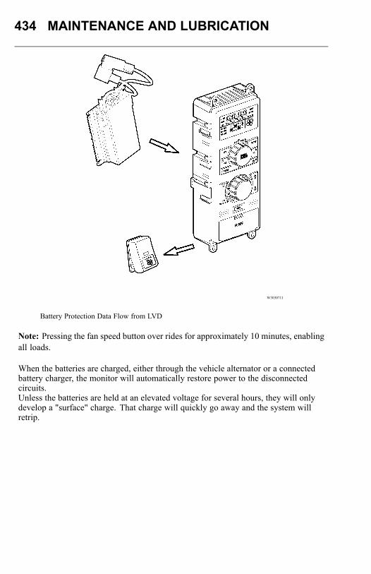
434 MAINTENANCE AND LUBRICATION
W3030711
Battery Protection Data Flow from LVD
Note: Pressing the fan speed button over rides for approximately 10 minutes, enablingall loads.
When the batteries are charged, either through the vehicle alternator or a connectedbattery charger, the monitor will automatically restore power to the disconnectedcircuits.Unless the batteries are held at an elevated voltage for several hours, they will onlydevelop a "surface" charge. That charge will quickly go away and the system willretrip.
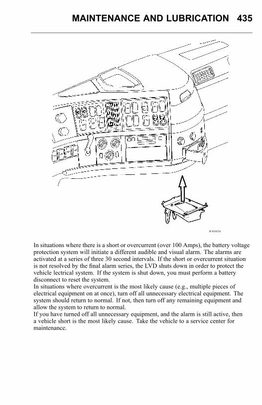
MAINTENANCE AND LUBRICATION 435
W3030520
In situations where there is a short or overcurrent (over 100 Amps), the battery voltageprotection system will initiate a different audible and visual alarm. The alarms areactivated at a series of three 30 second intervals. If the short or overcurrent situationis not resolved by the final alarm series, the LVD shuts down in order to protect thevehicle lectrical system. If the system is shut down, you must perform a batterydisconnect to reset the system.In situations where overcurrent is the most likely cause (e.g., multiple pieces ofelectrical equipment on at once), turn off all unnecessary electrical equipment. Thesystem should return to normal. If not, then turn off any remaining equipment andallow the system to return to normal.If you have turned off all unnecessary equipment, and the alarm is still active, thena vehicle short is the most likely cause. Take the vehicle to a service center formaintenance.
436 MAINTENANCE AND LUBRICATION
ELECTRICALGeneral Safety Guidelines
WARNING
Failure to repair a malfunction in theelectrical system can result in seriousdamage due to vehicle fire. Alwayslet an experienced electrical technicianperform repairs. Always determine thesource of the fault; do not just treat thesymptoms.
WARNING
Always wear eye protection whenworking around batteries to preventthe risk of injury due to contact withsulfuric acid or an explosion.
WARNING
Before replacing a damaged fuse, turnoff all functions for that circuit. Damageto the circuit can happen. Alwaysreplace fuses and circuit breakers withthe same current/amperage rating.Never substitute a fuse with foil, wire ornails. Increasing fuse or circuit breakerratings or substituting a fuse with foil,wire or nails may result in electricalcircuit overheating and possibly fire.
WARNING
Over-charging a poorly charged batterycan cause an explosion, which can leadto serious personal injury.
MAINTENANCE AND LUBRICATION 437
CAUTION
Attempting to work on electroniccomponents without proper equipmentcan damage internal parts with staticelectricity.
CAUTION
Today’s vehicles contain a high numberof electronic devices. It is veryimportant to exercise caution whenworking on a modern electrical system,charging batteries or jump starting theengine. To minimize the risk of anydamage to the electronic components,follow the procedures below when workis being done to the electrical system.
CAUTION
Welding on the vehicle can damage theelectrical system or components dueto the high voltage and current spikesthat normally occur when welding. Itis preferable to avoid welding on anassembled vehicle. However, if anystructure on or in contact with thevehicle must be welded, follow therecommendations below.
CAUTION
If there are other ground cablesconnected to the battery (such asengine ECU, transmission ECU,etc.), disconnect those wires first,then remove the main battery groundcable. Electronic modules may bedamaged when their ground(s) areconnected/disconnected with the mainbattery ground disconnected. Therefore,disconnect the main battery ground lastor when installing, connect the mainground first.
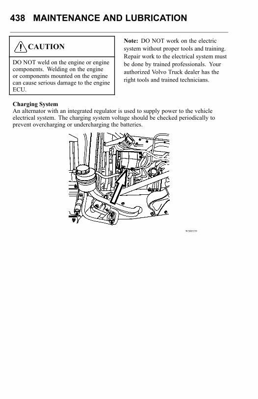
438 MAINTENANCE AND LUBRICATION
CAUTION
DO NOT weld on the engine or enginecomponents. Welding on the engineor components mounted on the enginecan cause serious damage to the engineECU.
Note: DO NOT work on the electricsystem without proper tools and training.Repair work to the electrical system mustbe done by trained professionals. Yourauthorized Volvo Truck dealer has theright tools and trained technicians.
Charging SystemAn alternator with an integrated regulator is used to supply power to the vehicleelectrical system. The charging system voltage should be checked periodically toprevent overcharging or undercharging the batteries.
W3005339
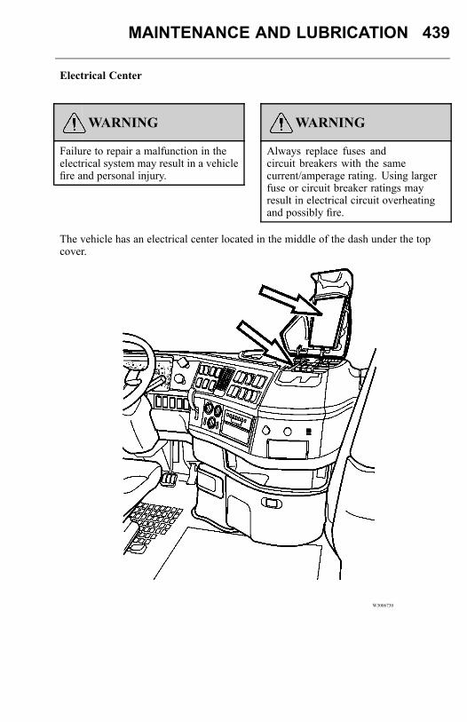
MAINTENANCE AND LUBRICATION 439
Electrical Center
WARNING
Failure to repair a malfunction in theelectrical system may result in a vehiclefire and personal injury.
WARNING
Always replace fuses andcircuit breakers with the samecurrent/amperage rating. Using largerfuse or circuit breaker ratings mayresult in electrical circuit overheatingand possibly fire.
The vehicle has an electrical center located in the middle of the dash under the topcover.
W3006730
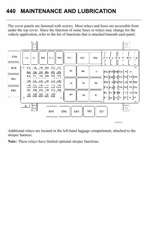
440 MAINTENANCE AND LUBRICATION
The cover panels are fastened with screws. Most relays and fuses are accessible fromunder the top cover. Since the function of some fuses or relays may change for thevehicle application, refer to the list of functions that is attached beneath each panel.
W3007220
Additional relays are located in the left-hand luggage compartment, attached to thesleeper harness.
Note: These relays have limited optional sleeper functions.
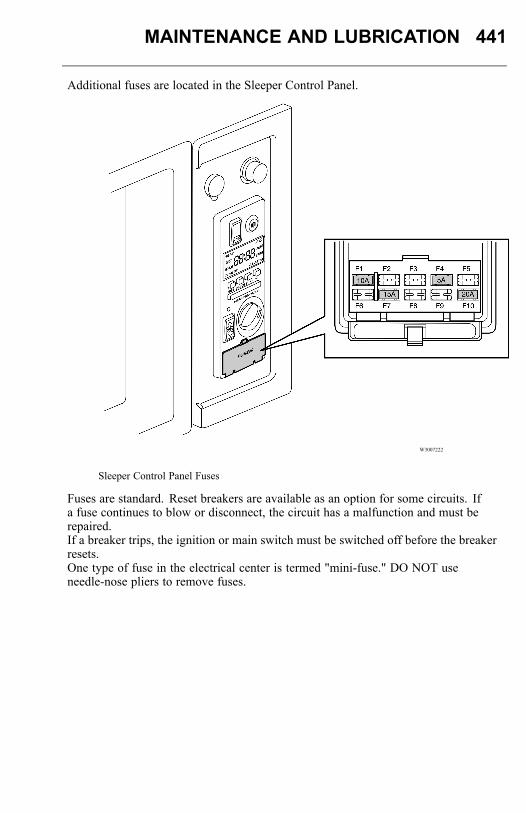
MAINTENANCE AND LUBRICATION 441
Additional fuses are located in the Sleeper Control Panel.
W3007222
Sleeper Control Panel Fuses
Fuses are standard. Reset breakers are available as an option for some circuits. Ifa fuse continues to blow or disconnect, the circuit has a malfunction and must berepaired.If a breaker trips, the ignition or main switch must be switched off before the breakerresets.One type of fuse in the electrical center is termed "mini-fuse." DO NOT useneedle-nose pliers to remove fuses.
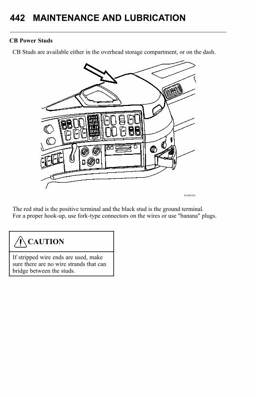
442 MAINTENANCE AND LUBRICATION
CB Power Studs
CB Studs are available either in the overhead storage compartment, or on the dash.
W3005282
The red stud is the positive terminal and the black stud is the ground terminal.For a proper hook-up, use fork-type connectors on the wires or use "banana" plugs.
CAUTION
If stripped wire ends are used, makesure there are no wire strands that canbridge between the studs.

MAINTENANCE AND LUBRICATION 443
Before connecting any electrical accessory, make sure it is made for 12 V operation.This circuit is fused at 20 A maximum, or optional circuits are fused at higher amps(30 A). DO NOT overload this circuit.
CAUTION
DO NOT connect a device with acurrent rating in excess of the amountspecified on the fuse and relay panels.
The dash top tray or the overhead radio shelf is available with an optional CB mountpower strap to hold different size radios securely in place.
444 METRIC CONVERSIONS
METRIC CONVERSIONSNote: Use all tools on the fasteners they were made to be used on. Use metric toolson Sl metric units only. Never try to use metric tools on U.S. standard fasteners orU.S. standard tools on Sl metric units.
CAUTION
Potential external/internal thread mismatch condition(s) may occur with certainmetric thread-inch thread fastener combinations, and with fastener combinationsinvolving incompatible metric fastener systems. A given thread mismatch conditioncan result in thread stripping and/or assembly weakness leading to potential servicefailure, thereby rendering a vehicle non-operational and/or unsafe for operation.The specific external/internal thread combinations from which such problems canresult are identified and set forth in Maintenance and Lubrication Manual (TS494).
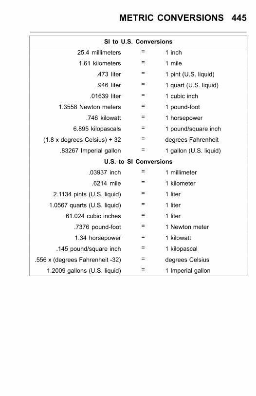
METRIC CONVERSIONS 445
SI to U.S. Conversions
25.4 millimeters = 1 inch
1.61 kilometers = 1 mile
.473 liter = 1 pint (U.S. liquid)
.946 liter = 1 quart (U.S. liquid)
.01639 liter = 1 cubic inch
1.3558 Newton meters = 1 pound-foot
.746 kilowatt = 1 horsepower
6.895 kilopascals = 1 pound/square inch
(1.8 x degrees Celsius) + 32 = degrees Fahrenheit
.83267 Imperial gallon = 1 gallon (U.S. liquid)
U.S. to SI Conversions
.03937 inch = 1 millimeter
.6214 mile = 1 kilometer
2.1134 pints (U.S. liquid) = 1 liter
1.0567 quarts (U.S. liquid) = 1 liter
61.024 cubic inches = 1 liter
.7376 pound-foot = 1 Newton meter
1.34 horsepower = 1 kilowatt
.145 pound/square inch = 1 kilopascal
.556 x (degrees Fahrenheit -32) = degrees Celsius
1.2009 gallons (U.S. liquid) = 1 Imperial gallon


Last page
Volvo Trucks North AmericaP.O. Box 26115, Greensboro, NC 27402-6115
Volvo Trucks Canada, Ltd.5600A Cancross Court, Missisauga, Ontario L5R 3E9
http://www.volvotrucks.com
PV776-21232734 English 4.2010© Volvo Group North America, Inc., 2010