Ford 6.7L Dual Remote Bypass System - Amsoil. OIL SUPPLY 1. Using an oil drain pan to capture lost...
4
IMPORTANT NOTICE • Read ALL instructions completely. • Improper installation can result in serious system and/or equipment damage. If you are uncomfortable with the instructions or have questions, do not attempt installation. Consult a mechanic or contact AMSOIL Technical Services at (715) 399-TECH for assistance. • WARNING: Extreme care should be taken to avoid bodily harm during installation. Before beginning, ensure engine is cool to avoid burns. Never work in the engine compartment with the engine running. It is advised that you perform a full oil change with installation of this system. A. BEFORE YOU BEGIN 1. Confirm all items on the Parts List are included in the Kit. 2. Ensure you have the required tools for the job. PARTS LIST Ford 6.7L Dual Remote Bypass System (BMK28) Item Description Qty. Part No. 1. Filter Mount Assembly 1 BK309 2. 1/4”-20 x 1” Hex Bolt Zinc 4 BP23 3. 1/4” Flat Washer Zinc SAE 6 BP21 4. 1/4”-20 Self Locking Nut Zinc 8 BP22 5. Fitting, 90˚, 7/8”-14 to 5/8” JIC 1 BP331 6. Fitting, Adapter, 7/8”-14 x 5/8” JIC 3 BP289 7. Fitting, 1/2” Hose, 7/8”-14 JIC 4 BP360 8. Hose, 1/2” ID 12’ BP350 9. Adapter, Filter, 3.24” OD 1 BP402 10. Thread Adapter, 1”-16 1 BP408 11. Gasket, 2.80” OD, 2.50” ID, 0.20” Thk. 1 BP196 12. O-ring, 1 3/16” ID x 0.10 Thk. 1 BP346 13. Bracket, Filter Mount Assembly, Top 1 BP194 14. Bracket, Filter Mount Assembly, Bottom 1 BP195 15. Hex Head Cap Screw Zinc Plate - 1/4”-20 x 1 1/2” 4 BP185 16. Fender Washer, SS 9/32” ID 4 BP186 17. Ea ® Oil Filter 1 EaO26 18. Ea ® Bypass Oil Filter 1 EaBP100 6” Nylon Cable Tie 4 BP46 Thread Sealant 1 BP198 BMK Mounting Template-BMK22, 23, 26, 27, 28 1 BP502 Instruction Sheet 1 BP28 OPTIONAL PARTS (Not Included)* Description Qty. Part No. Assembly, Oil Sample Petcock 1 BK13 Elbow, 90˚, 7/8”-14 JIC to 7/8”-14 JIC 1 BK21 Fitting, 45˚, 7/8”-14 JIC to 7/8”-14 JIC 1 BK22 *Not required, but available to ease installation. See www.amsoil.com or contact your AMSOIL Dealer. B. ATTACHING FILTER MOUNT 1. Survey the engine compartment for possible mounting locations. The mount should be located as close to the existing full-flow filter as possible. Select an area where the filtration system will not be damaged by road debris or off-road travel, and make sure the mounting structure is adequate to carry the weight of the filtration system. Reference Diagram A for an approximation of space required for mounting the system and removing filters. Reference Diagram B for appropriate mounting angles. 2. When the mounting location has been determined, put the provided mounting template sticker in place. Using a center punch and hammer, mark the centers of the drilling locations. 3. Using a 1/4” drill bit, drill the center-punched holes on the template, remove the sticker and attach the BP194 and BP195. Use the four 1” long 1⁄4” bolts, nuts, small washer and fender washers provided. See assembly Diagram D for details. Use a wrench to hold either the nut or bolt in place; use the socket and torque wrench on the opposite end to tighten to 8 ft-lbs. 4. In the same manner, attach the BK309 to the mounting brackets using four 1 1⁄2” long 1⁄4” bolts, nuts and washers provided. Warning: The bolts must be installed so the nuts are on the side opposite the filter nipples. Failure to do this will result in the bolts hitting the oil filters. Note: All fittings on the BK309 have been installed to the proper torque. There is no need to make any adjustment to these fittings unless installing a BK13. Ford 6.7L Dual Remote Bypass System Installation and Servicing Instructions BMK28 RECOMMENDED TOOL LIST • 1/4” drill bit • 7/16” wrench • 7/16” socket • 1” socket • 1” wrench (2) • 1” crow foot adapter • Center punch • Hammer • Adjustable filter wrench • Torque wrench • Drain oil pan • Vice • Drill • Utility knife • Hose cutter • Proper socket for thread adapter
Transcript of Ford 6.7L Dual Remote Bypass System - Amsoil. OIL SUPPLY 1. Using an oil drain pan to capture lost...

IMPORTANT NOTICE• Read ALL instructions completely.• Improper installation can result in serious system and/or equipment
damage. If you are uncomfortable with the instructions or have questions, do not attempt installation. Consult a mechanic or contact AMSOIL Technical Services at (715) 399-TECH for assistance.
• WARNING: Extreme care should be taken to avoid bodily harm during installation. Before beginning, ensure engine is cool to avoid burns. Never work in the engine compartment with the engine running. It is advised that you perform a full oil change with installation of this system.
A. BEFORE YOU BEGIN1. ConfirmallitemsonthePartsListareincludedintheKit.2. Ensure you have the required tools for the job.
PARTS LISTFord 6.7L Dual Remote Bypass System (BMK28)Item Description Qty. Part No.1. FilterMountAssembly 1 BK3092. 1/4”-20x1”HexBoltZinc 4 BP233. 1/4”FlatWasherZincSAE 6 BP214. 1/4”-20SelfLockingNutZinc 8 BP225. Fitting,90˚,7/8”-14to5/8”JIC 1 BP3316. Fitting,Adapter,7/8”-14x5/8”JIC 3 BP2897. Fitting,1/2”Hose,7/8”-14JIC 4 BP3608. Hose,1/2”ID 12’ BP3509. Adapter,Filter,3.24”OD 1 BP40210. ThreadAdapter,1”-16 1 BP40811. Gasket,2.80”OD,2.50”ID,0.20”Thk. 1 BP19612. O-ring,13/16”IDx0.10Thk. 1 BP34613. Bracket,FilterMountAssembly,Top 1 BP19414. Bracket,FilterMountAssembly,Bottom 1 BP19515. HexHeadCapScrewZincPlate-
1/4”-20x11/2” 4 BP18516. FenderWasher,SS9/32”ID 4 BP18617. Ea®OilFilter 1 EaO2618. Ea®BypassOilFilter 1 EaBP100 6”NylonCableTie 4 BP46 ThreadSealant 1 BP198 BMKMountingTemplate-BMK22,23, 26,27,28 1 BP502 InstructionSheet 1 BP28
OPTIONAL PARTS (Not Included)*Description Qty. Part No.Assembly,OilSamplePetcock 1 BK13Elbow,90˚,7/8”-14JICto7/8”-14JIC 1 BK21Fitting,45˚,7/8”-14JICto7/8”-14JIC 1 BK22
* Not required, but available to ease installation. Seewww.amsoil.comorcontactyourAMSOILDealer.
B. ATTACHING FILTER MOUNT1. Survey the engine compartment for possible mounting locations. Themountshouldbelocatedasclosetotheexistingfull-flowfilteraspossible.Selectanareawherethefiltrationsystemwillnotbe damaged by road debris or off-road travel, and make sure the mountingstructureisadequatetocarrytheweightofthefiltrationsystem.ReferenceDiagramAforanapproximationofspacerequiredformountingthesystemandremovingfilters.ReferenceDiagramBforappropriatemountingangles.
2. When the mounting location has been determined, put the provided mounting template sticker in place. Using a center punch and hammer, mark the centers of the drilling locations.
3. Using a 1/4” drill bit, drill the center-punched holes on the template,removethestickerandattachtheBP194andBP195.Usethefour1”long1⁄4”bolts,nuts,smallwasherandfenderwashersprovided.SeeassemblyDiagramDfordetails.Useawrenchtohold either the nut or bolt in place; use the socket and torque wrenchontheoppositeendtotightento8ft-lbs.
4.Inthesamemanner,attachtheBK309tothemountingbracketsusingfour11⁄2”long1⁄4”bolts,nutsandwashersprovided.
Warning: The bolts must be installed so the nuts are on the side oppositethefilternipples.Failuretodothiswillresultintheboltshittingtheoilfilters.
Note:AllfittingsontheBK309havebeeninstalledtothepropertorque.ThereisnoneedtomakeanyadjustmenttothesefittingsunlessinstallingaBK13.
Ford 6.7L Dual Remote Bypass SystemInstallation and Servicing Instructions
BMK28
RECOMMENDED TOOL LIST• 1/4” drill bit• 7/16” wrench• 7/16” socket• 1” socket• 1” wrench (2)• 1” crow foot adapter
• Center punch• Hammer• Adjustable filter
wrench• Torque wrench• Drain oil pan
• Vice• Drill• Utility knife• Hose cutter• Proper socket for
thread adapter

C. OIL SUPPLY1. Usinganoildrainpantocapturelostoil,removetheexistingfull-flowenginefilter.Cleanthegasketseatingareaontheenginewithalint-freecloth.
2.TemporarilythreadtheBP402andBP408ontotheengineanddetermine the direction in which you would like the hoses to intersecttheadapterassemby.InstallationoftheBP289andBP331fittingscanbeperformedoneoftwowaysasshownbelow.Choosethe best method to ensure a smooth hose transition to and from the engine. Remove the assembly from the engine.
3.ApplythreadsealantasnotedinDiagramContheBP289andBP331.ThesealantshouldbeplacedontheO-ring-sidethreadonly.
4. Lubricate the O-ring oftheBP289andinstall in the adapter assembly. If installing intotheBP408(asinOption2),tightento85ft-lbs. If installing into thesideoftheBP402(as in Option 1), tightento56ft-lbs.
5.LubricatetheO-ringontheBP331andinstallintheadapterassembly, turning until the washer contacts the face. Unscrew up toonefullturntopointthefittinginthedesireddirection.Usingawrenchtoholdthefittingbody,usea1”crowfootwrenchtotightenthelockingnutto85ft-lbsifinstallingintheBP408(asinOption1),or56ft-lbsifinstallinginthesideoftheBP402(asinOption2).
6.Applyathincoatofoilonthespin-onadaptergasketandtheadapter nut O-ring.
7.Reassembleadapterandinstallonengine.Makesurefittingsarecorrectly positioned and tighten the adapter assembly onto the engine,firsttighteningtheBP408tofinger-tight,thentighteninganadditional3/4turnpastfinger-tight.
D. OIL FEED AND RETURN LINES
• NOTE:Thehoseandhosefittingssuppliedwiththiskitarematched to provide maximum performance and life expectancy. Interchanging with other types or brands is not recommended and should be avoided. Should additional hose be required, it may beobtainedfromAMSOILbyorderingpartnumberBP350bythefoot.
• DO NOT install oil hoses near hot exhaust parts or near sharp metal components that could cause abrasive wear.
• DO NOT create sharp bends in oil hoses when installing.
• NOTE:Paycloseattentiontothehoseroutingandconnections.Improperly connecting the feed and return lines could result in oil starvation and potential engine failure.
1. OIL SUPPLY HOSE, • Measure the amountofhose(BP350)neededto route from the side port on the spin-on adapter (labeled A) to the port with arrow pointing IN on the filtermount.• Ensure a minimum bend radius of 2 1⁄49 is maintained at all corners. Also, bends in hose shouldnotbeginathosefittings.
Note:Ensurehosehassignificantadditionallengthtoaccommodate movement of engine.
2. HOSE FITTING ASSEMBLY INSTRUCTIONSa. Using a utility knife or hose cutter, squarely cut the hose to the
proper length (Step 2a).b.InstallBP360onbothendsofthecuthose.Screwnutportionofthefittingcounter-clockwise onto hose until it bottoms. Back hose out 1/2 turn (Step 2b).
Note:Donotuseanyformofthreadsealantanywhereonthehosefittings(BP360).
c. Oil tapered nipple thread areas liberally with oil. You may also oil insideofhose.Donotoilhosecover(Step2c).
d. Screw nipple thread into socket using wrench on nipple hex until nipple hex shoulders against socket (Steps 2d, 2e, 2f).
3. Route and connect the hose assembly for the oil supply. Run the hose fromthesideportontheBP402labeledA to the port with the arrow pointing INontheBK309.(BK21orBK22maybeinstalledatthistimebetweenthehosefittingandmountorspin-on adapter.)
4.Onbothendstightenthenutfinger-tight.Placeamarkonthemiddleofoneflatofthenut.Startingfromthisposition, tighten the nut further by 1.5flatsusingonewrenchtoholdtheBP289andtheothertoturnthenutontheBP360.(Aflatisreferredtoasone side of the hexagonal tube nut and equatesto1/6ofaturn.)
A
2a. 2b.
2c. 2d.
2e. 2f.
NO SEALANTON FIRST 1-2 THREADS
SEALANT AREA
SEALANT AREA
NO SEALANTON FIRST 1-2 THREADS
Diagram C
BP289BP331
OPTION 1 OPTION 2
FinishFinishStartStart
Start
1/ 21 Flat
Rotate
5. OIL RETURN HOSE, Repeat Steps D.1throughD.4.Connecthoseat the thread adapter port labeled B and the port with the arrow pointing OUTontheBK309.
6.Useplasticties(BP46)tosecurehose in position and away from potential damage. Trim ties with side cutter. Note: Over tightening the plastic ties may cause the hose to
collapseandrestrictoilflow.7.Fillthefull-flowfilterandbypassfilterwiththesameengineoilbeingusedinthevehicle.Lubricatethefiltergasketswithoilandspinfiltersontomount.Tightenperinstructionsonthefilter.
E. STARTUP PROCEDURES1.Checkthatallfittingsandhoses
are securely attached, and that the hoses are routed properly.
2. Check engine oil level. Fill to full mark on the engine dipstick if necessary.
3. With the equipment secured start the engine and immediately check oil pressure. Note:Pressuremayinitiallytakeamomentor two to rise.
Caution:Carefullycheckforleaksatfittings,hosesandmount.If leaks are observed, STOP ENGINE IMMEDIATELY, repair leaks and continue.
Caution: If no oil pressure registers on the gauge, STOP ENGINE IMMEDIATELY, check hose connections and oil level, and review StartupProcedures.
4. After engine has warmed, shut off and re-check engine oil level. Top off as necessary.
5. Record date of installation and equipment operating hours or mileage.
F. PERIODIC MAINTENANCE1.Duringthewarrantyperiod,annuallyinspectfittingsandhoses.
Check for leaks, hose deterioration and cuts. Repair and/or replace as necessary. See the AMSOIL Limited Warranty – Bypass Filter Systems at www.amsoil.com for complete information.
2.Tochangethefilterelements: a. Ensure engine is off and use caution as the engine, oil and
filtermaybehotandcouldresultininjury. b.Usingafilterwrench,removethefilterelements.Disposeof
properly. c.Cleanthefiltergasketcontactareasonthemountwithaclean,
lint-free rag. d.Lubricatethenewfiltergasketswithcleanoil. e.Fillfiltersasfullaspossiblewithengineoil. f.Screwonnewfilters,tightenperinstructionsonthefilter. g. Start engine and check for leaks. h.Checkengineoillevel,fillasneeded.3. Record date of installation and equipment operating hours or
mileage for future reference.
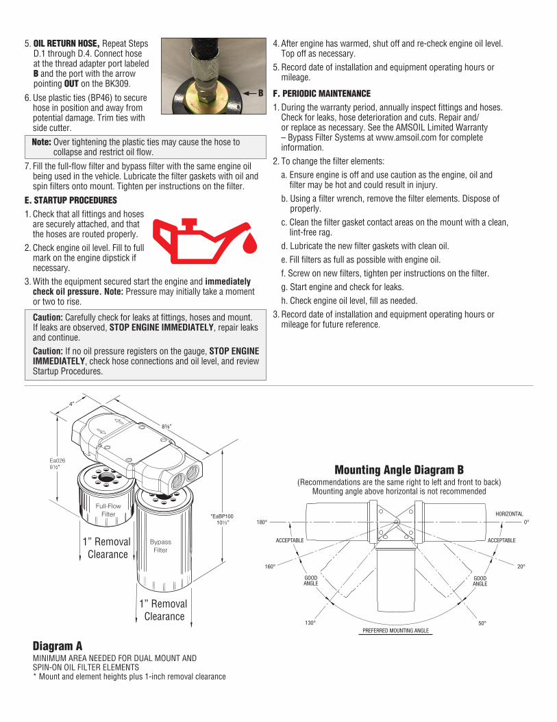
Mounting Angle Diagram B(Recommendations are the same right to left and front to back)
Mounting angle above horizontal is not recommended
GOODANGLE
ACCEPTABLE ACCEPTABLE
GOODANGLE
PREFERRED MOUNTING ANGLE
HORIZONTAL0°
20°
50°130°
160°
180°
Ea0268
1” Removal Clearance
1” Removal Clearance
BypassFilter
Full-Flow Filter
Diagram AMINIMUMAREANEEDEDFORDUALMOUNTANDSPIN-ONOILFILTERELEMENTS* Mount and element heights plus 1-inch removal clearance
B

AMSOIL INC., 925 Tower Ave., Superior, WI 54880 • 715-392-7101 • Printed in the USA. © 2017, AMSOIL INC. All rights reserved. The AMSOIL logo is a registered trademark of AMSOIL INC. BP28 12/17
13
16
4
14
3 15
15
15
2
15
2
2
3
4
Diagram D
INSTALLING AN OIL SAMPLING PETCOCK ON THE SPIN-ON BYPASS:Getting a clean and uncontaminated oil sample is easy and simple when an oil sampling petcock is installed intothefiltermountassembly.OrderkitBK13.
Oil Analysis:Visit www.oaitesting.com for specifickits.
8
7
9
10
6
6
7
5
6
7
8
7
1
12
11
17
18
Optional BK13SamplingKit
AMSOILFull-Flow Filter
AMSOIL Bypass Filter