(for TEMPpoint, VOLTpoint, and MEASURpoint Instruments)
190
SCPI Programmer’s UM-23650-L Manual for LXI MEASURpoint Instruments) (for TEMPpoint, VOLTpoint, and Measurement Instruments Title Page
Transcript of (for TEMPpoint, VOLTpoint, and MEASURpoint Instruments)

SCPI Programmer’s
UM-23650-L
Manual for LXI
MEASURpoint Instruments)
(for TEMPpoint, VOLTpoint, and
Measurement Instruments
Title Page

Copyright Page
Trademark and Copyright Information
Measurement Computing Corporation, InstaCal, Universal Library, and the Measurement Computing logo are either trademarks or registered trademarks of Measurement Computing Corporation. Refer to the Copyrights & Trademarks section on mccdaq.com/legal for more information about Measurement Computing trademarks.
Other product and company names mentioned herein are trademarks or trade names of their respective companies.
© 2018 Measurement Computing Corporation. All rights reserved. No part of this publication may be reproduced, stored in a retrieval system, or transmitted, in any form by any means, electronic, mechanical, by photocopying, recording, or otherwise without the prior written permission of Measurement Computing Corporation.
Notice
Measurement Computing Corporation does not authorize any Measurement Computing Corporation product for use in life support systems and/or devices without prior written consent from Measurement Computing Corporation. Life support devices/systems are devices or systems that, a) are intended for surgical implantation into the body, or b) support or sustain life and whose failure to perform can be reasonably expected to result in injury. Measurement Computing Corporation products are not designed with the components required, and are not subject to the testing required to ensure a level of reliability suitable for the treatment and diagnosis of people.

Table of Contents
Table of Contents
About this Manual . . . . . . . . . . . . . . . . . . . . . . . . . . . . . . . . . . . . . . . . . . . . . . . . . . . . . . 9
Intended Audience. . . . . . . . . . . . . . . . . . . . . . . . . . . . . . . . . . . . . . . . . . . . . . . . . . . . . . . . . . . . . 9
What You Should Learn from this Manual. . . . . . . . . . . . . . . . . . . . . . . . . . . . . . . . . . . . . . . . . 9
Conventions Used in this Manual . . . . . . . . . . . . . . . . . . . . . . . . . . . . . . . . . . . . . . . . . . . . . . . 10
Related Documents . . . . . . . . . . . . . . . . . . . . . . . . . . . . . . . . . . . . . . . . . . . . . . . . . . . . . . . . . . . 10
Where to Get Help . . . . . . . . . . . . . . . . . . . . . . . . . . . . . . . . . . . . . . . . . . . . . . . . . . . . . . . . . . . . 10
Chapter 1: Syntax Conventions . . . . . . . . . . . . . . . . . . . . . . . . . . . . . . . . . . . . . . . . . . 11
Introduction. . . . . . . . . . . . . . . . . . . . . . . . . . . . . . . . . . . . . . . . . . . . . . . . . . . . . . . . . . . . . . . . . . 12
Types of SCPI Messages . . . . . . . . . . . . . . . . . . . . . . . . . . . . . . . . . . . . . . . . . . . . . . . . . . . . 12
Types of SCPI Commands . . . . . . . . . . . . . . . . . . . . . . . . . . . . . . . . . . . . . . . . . . . . . . . . . . 12
Common SCPI Commands . . . . . . . . . . . . . . . . . . . . . . . . . . . . . . . . . . . . . . . . . . . . . 12
SCPI Subsystem Commands . . . . . . . . . . . . . . . . . . . . . . . . . . . . . . . . . . . . . . . . . . . . 14
Syntax of Program Messages . . . . . . . . . . . . . . . . . . . . . . . . . . . . . . . . . . . . . . . . . . . . . . . . . . . 19
Syntax of Common SCPI Commands . . . . . . . . . . . . . . . . . . . . . . . . . . . . . . . . . . . . . . . . 20
Syntax of SCPI Subsystem Commands . . . . . . . . . . . . . . . . . . . . . . . . . . . . . . . . . . . . . . . 20
About Short- and Long-Form Mnemonics . . . . . . . . . . . . . . . . . . . . . . . . . . . . . . . . 21
About Brackets, Braces, and Vertical Bars . . . . . . . . . . . . . . . . . . . . . . . . . . . . . . . . . 21
Syntax of Response Messages. . . . . . . . . . . . . . . . . . . . . . . . . . . . . . . . . . . . . . . . . . . . . . . . . . . 22
SCPI Data Types . . . . . . . . . . . . . . . . . . . . . . . . . . . . . . . . . . . . . . . . . . . . . . . . . . . . . . . . . . . . . . 23
Character Data Types . . . . . . . . . . . . . . . . . . . . . . . . . . . . . . . . . . . . . . . . . . . . . . . . . . . . . . 23
String Data Types . . . . . . . . . . . . . . . . . . . . . . . . . . . . . . . . . . . . . . . . . . . . . . . . . . . . . . . . . 23
<NR1>Value Data Type . . . . . . . . . . . . . . . . . . . . . . . . . . . . . . . . . . . . . . . . . . . . . . . . . . . . 24
<NR2> Value Data Type. . . . . . . . . . . . . . . . . . . . . . . . . . . . . . . . . . . . . . . . . . . . . . . . . . . . 24
<NRr>Value Data Type . . . . . . . . . . . . . . . . . . . . . . . . . . . . . . . . . . . . . . . . . . . . . . . . . . . . 24
<NRf>Value Data Type . . . . . . . . . . . . . . . . . . . . . . . . . . . . . . . . . . . . . . . . . . . . . . . . . . . . 25
<Boolean> Data Type . . . . . . . . . . . . . . . . . . . . . . . . . . . . . . . . . . . . . . . . . . . . . . . . . . . . . . 26
<Block> Data Type . . . . . . . . . . . . . . . . . . . . . . . . . . . . . . . . . . . . . . . . . . . . . . . . . . . . . . . . 26
SCPI Expression Types . . . . . . . . . . . . . . . . . . . . . . . . . . . . . . . . . . . . . . . . . . . . . . . . . . . . . . . . 27
Numeric Expressions . . . . . . . . . . . . . . . . . . . . . . . . . . . . . . . . . . . . . . . . . . . . . . . . . . . . . . 27
Channel Lists . . . . . . . . . . . . . . . . . . . . . . . . . . . . . . . . . . . . . . . . . . . . . . . . . . . . . . . . . . . . . 28
Numeric Lists. . . . . . . . . . . . . . . . . . . . . . . . . . . . . . . . . . . . . . . . . . . . . . . . . . . . . . . . . . . . . 29
Data Interchange Format (DIF) Expressions . . . . . . . . . . . . . . . . . . . . . . . . . . . . . . . . . . . 30
Instrument-Specifier Expressions . . . . . . . . . . . . . . . . . . . . . . . . . . . . . . . . . . . . . . . . . . . . 31
Chapter 2: Using SCPI Commands with LXI Measurement Instruments . . . . . . . . . 33
Installing SCPI Support Files . . . . . . . . . . . . . . . . . . . . . . . . . . . . . . . . . . . . . . . . . . . . . . . . . . . 34
Determining the LAN Settings of Your Instrument . . . . . . . . . . . . . . . . . . . . . . . . . . . . . . . . 35
Using Password-Protected Commands . . . . . . . . . . . . . . . . . . . . . . . . . . . . . . . . . . . . . . . . . . 36
3

Contents
4
Determining the System Configuration . . . . . . . . . . . . . . . . . . . . . . . . . . . . . . . . . . . . . . . . . . 40
Performing Analog Input Operations . . . . . . . . . . . . . . . . . . . . . . . . . . . . . . . . . . . . . . . . . . . . 41
Analog Input Channels . . . . . . . . . . . . . . . . . . . . . . . . . . . . . . . . . . . . . . . . . . . . . . . . . . . . 41
Input Ranges . . . . . . . . . . . . . . . . . . . . . . . . . . . . . . . . . . . . . . . . . . . . . . . . . . . . . . . . . . . . . 41
Filtering. . . . . . . . . . . . . . . . . . . . . . . . . . . . . . . . . . . . . . . . . . . . . . . . . . . . . . . . . . . . . . . . . . 42
Conversion Modes . . . . . . . . . . . . . . . . . . . . . . . . . . . . . . . . . . . . . . . . . . . . . . . . . . . . . . . . 43
Simultaneous Single-Value Operations . . . . . . . . . . . . . . . . . . . . . . . . . . . . . . . . . . . 43
Continuous Scan Mode . . . . . . . . . . . . . . . . . . . . . . . . . . . . . . . . . . . . . . . . . . . . . . . . 44
Configuring Channels for a Continuous Scan Operation. . . . . . . . . . . . . . . . . 44
Returning CJC Values in the Data Stream. . . . . . . . . . . . . . . . . . . . . . . . . . . . . . 45
Specifying a Channel List for a Continuous Scan Operation . . . . . . . . . . . . . . 45
Specifying the Scan Rate . . . . . . . . . . . . . . . . . . . . . . . . . . . . . . . . . . . . . . . . . . . . 46
Specifying the Trigger Source . . . . . . . . . . . . . . . . . . . . . . . . . . . . . . . . . . . . . . . . 46
Initiating and Aborting a Continuous Scan Operation . . . . . . . . . . . . . . . . . . . 46
Storing Data in the Circular Buffer. . . . . . . . . . . . . . . . . . . . . . . . . . . . . . . . . . . . 47
Retrieving Scan Data from the Circular Buffer. . . . . . . . . . . . . . . . . . . . . . . . . . 48
Auto-Calibration . . . . . . . . . . . . . . . . . . . . . . . . . . . . . . . . . . . . . . . . . . . . . . . . . . . . . . . . . . 52
Performing Digital Input Operations . . . . . . . . . . . . . . . . . . . . . . . . . . . . . . . . . . . . . . . . . . . . 53
Performing Digital Output Operations. . . . . . . . . . . . . . . . . . . . . . . . . . . . . . . . . . . . . . . . . . . 54
Chapter 3: Common SCPI Commands . . . . . . . . . . . . . . . . . . . . . . . . . . . . . . . . . . . . 55
Clear Status (*CLS) . . . . . . . . . . . . . . . . . . . . . . . . . . . . . . . . . . . . . . . . . . . . . . . . . . . . . . . . . . . . 56Standard Event Status Enable Register (*ESE) . . . . . . . . . . . . . . . . . . . . . . . . . . . . . . . . . . . . . 56Standard Event Status Enable Register Query (*ESE?). . . . . . . . . . . . . . . . . . . . . . . . . . . . . . 57Standard Event Status Register Query (*ESR?) . . . . . . . . . . . . . . . . . . . . . . . . . . . . . . . . . . . . 57Identification Query (*IDN?) . . . . . . . . . . . . . . . . . . . . . . . . . . . . . . . . . . . . . . . . . . . . . . . . . . . 59Operation Complete (*OPC) . . . . . . . . . . . . . . . . . . . . . . . . . . . . . . . . . . . . . . . . . . . . . . . . . . . . 60Operation Complete Query (*OPC?) . . . . . . . . . . . . . . . . . . . . . . . . . . . . . . . . . . . . . . . . . . . . . 60Reset (*RST) . . . . . . . . . . . . . . . . . . . . . . . . . . . . . . . . . . . . . . . . . . . . . . . . . . . . . . . . . . . . . . . . . . 60Self-Test Query (*TST?) . . . . . . . . . . . . . . . . . . . . . . . . . . . . . . . . . . . . . . . . . . . . . . . . . . . . . . . . 61Service Request Enable (*SRE) . . . . . . . . . . . . . . . . . . . . . . . . . . . . . . . . . . . . . . . . . . . . . . . . . . 61Service Request Enable Query (*SRE?) . . . . . . . . . . . . . . . . . . . . . . . . . . . . . . . . . . . . . . . . . . . 62Read Status Byte Query (*STB?). . . . . . . . . . . . . . . . . . . . . . . . . . . . . . . . . . . . . . . . . . . . . . . . . 62Wait-to-Continue (*WAI). . . . . . . . . . . . . . . . . . . . . . . . . . . . . . . . . . . . . . . . . . . . . . . . . . . . . . . 63
Chapter 4: SCPI Subsystem Commands. . . . . . . . . . . . . . . . . . . . . . . . . . . . . . . . . . . 65
SCPI Subsystem Command Hierarchy . . . . . . . . . . . . . . . . . . . . . . . . . . . . . . . . . . . . . . . . . . . 66
STATus Subsystem Commands . . . . . . . . . . . . . . . . . . . . . . . . . . . . . . . . . . . . . . . . . . . . . . . . . 68
Operation Condition Query . . . . . . . . . . . . . . . . . . . . . . . . . . . . . . . . . . . . . . . . . . . . . . . . 69
Operation Event Register Enable . . . . . . . . . . . . . . . . . . . . . . . . . . . . . . . . . . . . . . . . . . . . 70
Operation Enable Register Query . . . . . . . . . . . . . . . . . . . . . . . . . . . . . . . . . . . . . . . . . . . 70
Operation Event Register Query . . . . . . . . . . . . . . . . . . . . . . . . . . . . . . . . . . . . . . . . . . . . 71
Presetting Registers . . . . . . . . . . . . . . . . . . . . . . . . . . . . . . . . . . . . . . . . . . . . . . . . . . . . . . . 71

Contents
Questionable Condition Register Query . . . . . . . . . . . . . . . . . . . . . . . . . . . . . . . . . . . . . . 72
Questionable Enable Register . . . . . . . . . . . . . . . . . . . . . . . . . . . . . . . . . . . . . . . . . . . . . . . 72
Questionable Enable Register Query . . . . . . . . . . . . . . . . . . . . . . . . . . . . . . . . . . . . . . . . 73
Questionable Event Register Query . . . . . . . . . . . . . . . . . . . . . . . . . . . . . . . . . . . . . . . . . 73
Scan Record Status Query . . . . . . . . . . . . . . . . . . . . . . . . . . . . . . . . . . . . . . . . . . . . . . . . . . 74
SYSTem Subsystem Commands. . . . . . . . . . . . . . . . . . . . . . . . . . . . . . . . . . . . . . . . . . . . . . . . . 75
Auto-Calibrate . . . . . . . . . . . . . . . . . . . . . . . . . . . . . . . . . . . . . . . . . . . . . . . . . . . . . . . . . . . 77
DATE Query . . . . . . . . . . . . . . . . . . . . . . . . . . . . . . . . . . . . . . . . . . . . . . . . . . . . . . . . . . . . . 77
ERRor Query . . . . . . . . . . . . . . . . . . . . . . . . . . . . . . . . . . . . . . . . . . . . . . . . . . . . . . . . . . . . . 78
ERRor Count Query . . . . . . . . . . . . . . . . . . . . . . . . . . . . . . . . . . . . . . . . . . . . . . . . . . . . . . . 79
LAN Configuration Reset . . . . . . . . . . . . . . . . . . . . . . . . . . . . . . . . . . . . . . . . . . . . . . . . . . 80
LAN IP Address Query . . . . . . . . . . . . . . . . . . . . . . . . . . . . . . . . . . . . . . . . . . . . . . . . . . . . 80
LAN IP Subnet Mask Query . . . . . . . . . . . . . . . . . . . . . . . . . . . . . . . . . . . . . . . . . . . . . . . . 80
Password - Disable Password-Protected Commands . . . . . . . . . . . . . . . . . . . . . . . . . . . 81
Password - Enable Password-Protected Commands . . . . . . . . . . . . . . . . . . . . . . . . . . . 83
Password - Query Password Enable State . . . . . . . . . . . . . . . . . . . . . . . . . . . . . . . . . . . . 85
Password - Set New Password . . . . . . . . . . . . . . . . . . . . . . . . . . . . . . . . . . . . . . . . . . . . . . 86
SCPI Version Query . . . . . . . . . . . . . . . . . . . . . . . . . . . . . . . . . . . . . . . . . . . . . . . . . . . . . . . 88
Supported Board Number Query . . . . . . . . . . . . . . . . . . . . . . . . . . . . . . . . . . . . . . . . . . . 88
Supported Board Model Query . . . . . . . . . . . . . . . . . . . . . . . . . . . . . . . . . . . . . . . . . . . . . 89
Supported Board Model Name Query . . . . . . . . . . . . . . . . . . . . . . . . . . . . . . . . . . . . . . . 90
Supported Board Voltage Range Query . . . . . . . . . . . . . . . . . . . . . . . . . . . . . . . . . . . . . . 91
Supported Channels Query . . . . . . . . . . . . . . . . . . . . . . . . . . . . . . . . . . . . . . . . . . . . . . . . 92
Supported RTD Channels Query . . . . . . . . . . . . . . . . . . . . . . . . . . . . . . . . . . . . . . . . . . . . 93
Supported Thermocouple Channels Query . . . . . . . . . . . . . . . . . . . . . . . . . . . . . . . . . . . 94
Supported Voltage Range Query . . . . . . . . . . . . . . . . . . . . . . . . . . . . . . . . . . . . . . . . . . . . 95
Supported Digital Input Lines Query . . . . . . . . . . . . . . . . . . . . . . . . . . . . . . . . . . . . . . . . 96
Supported Digital Output Lines Query . . . . . . . . . . . . . . . . . . . . . . . . . . . . . . . . . . . . . . 96
Supported Maximum Scan Rate Query . . . . . . . . . . . . . . . . . . . . . . . . . . . . . . . . . . . . . . 97
Supported Minimum Scan Rate Query . . . . . . . . . . . . . . . . . . . . . . . . . . . . . . . . . . . . . . . 98
TIME Query . . . . . . . . . . . . . . . . . . . . . . . . . . . . . . . . . . . . . . . . . . . . . . . . . . . . . . . . . . . . . 99
Time Zone Query . . . . . . . . . . . . . . . . . . . . . . . . . . . . . . . . . . . . . . . . . . . . . . . . . . . . . . . . 100
Time Zone Set . . . . . . . . . . . . . . . . . . . . . . . . . . . . . . . . . . . . . . . . . . . . . . . . . . . . . . . . . . . 100
CONFigure Subsystem Commands . . . . . . . . . . . . . . . . . . . . . . . . . . . . . . . . . . . . . . . . . . . . 102
Channel Configuration for Resistance . . . . . . . . . . . . . . . . . . . . . . . . . . . . . . . . . . . . . . 103
Channel Configuration for RTD Temperatures . . . . . . . . . . . . . . . . . . . . . . . . . . . . . . . 104
Channel Configuration for Thermocouple Temperatures . . . . . . . . . . . . . . . . . . . . . . 106
Channel Configuration for Voltage . . . . . . . . . . . . . . . . . . . . . . . . . . . . . . . . . . . . . . . . . 109
Channel Configuration for Programmable Voltage Ranges . . . . . . . . . . . . . . . . . . . . 111
Channel Configuration Query . . . . . . . . . . . . . . . . . . . . . . . . . . . . . . . . . . . . . . . . . . . . . 113
Filter Configuration . . . . . . . . . . . . . . . . . . . . . . . . . . . . . . . . . . . . . . . . . . . . . . . . . . . . . . 115
Filter Query . . . . . . . . . . . . . . . . . . . . . . . . . . . . . . . . . . . . . . . . . . . . . . . . . . . . . . . . . . . . . 116
5

Contents
6
Scan Circular Buffer Query . . . . . . . . . . . . . . . . . . . . . . . . . . . . . . . . . . . . . . . . . . . . . . . . 117
Scan CJC Configuration . . . . . . . . . . . . . . . . . . . . . . . . . . . . . . . . . . . . . . . . . . . . . . . . . . 118
Scan CJC Query . . . . . . . . . . . . . . . . . . . . . . . . . . . . . . . . . . . . . . . . . . . . . . . . . . . . . . . . . 119
Scan List Configuration . . . . . . . . . . . . . . . . . . . . . . . . . . . . . . . . . . . . . . . . . . . . . . . . . . . 120
Scan List Query . . . . . . . . . . . . . . . . . . . . . . . . . . . . . . . . . . . . . . . . . . . . . . . . . . . . . . . . . . 122
Scan Rate Configuration . . . . . . . . . . . . . . . . . . . . . . . . . . . . . . . . . . . . . . . . . . . . . . . . . . 123
Scan Rate Query . . . . . . . . . . . . . . . . . . . . . . . . . . . . . . . . . . . . . . . . . . . . . . . . . . . . . . . . . 125
Trigger Source Configuration . . . . . . . . . . . . . . . . . . . . . . . . . . . . . . . . . . . . . . . . . . . . . . 127
Trigger Source Query . . . . . . . . . . . . . . . . . . . . . . . . . . . . . . . . . . . . . . . . . . . . . . . . . . . . . 128
MEASure Subsystem Commands . . . . . . . . . . . . . . . . . . . . . . . . . . . . . . . . . . . . . . . . . . . . . . 129
Measure Single Resistance Values . . . . . . . . . . . . . . . . . . . . . . . . . . . . . . . . . . . . . . . . . . 130
Measure Single RTD Temperature Values . . . . . . . . . . . . . . . . . . . . . . . . . . . . . . . . . . . 131
Measure Single Thermocouple Temperature Values . . . . . . . . . . . . . . . . . . . . . . . . . . 134
Measure Single Voltage Values . . . . . . . . . . . . . . . . . . . . . . . . . . . . . . . . . . . . . . . . . . . . . 137
INITiate Subsystem Command . . . . . . . . . . . . . . . . . . . . . . . . . . . . . . . . . . . . . . . . . . . . . . . . 140
INITiate Scan . . . . . . . . . . . . . . . . . . . . . . . . . . . . . . . . . . . . . . . . . . . . . . . . . . . . . . . . . . . . 140
ABORt Subsystem Command . . . . . . . . . . . . . . . . . . . . . . . . . . . . . . . . . . . . . . . . . . . . . . . . . 143
ABORt Scan . . . . . . . . . . . . . . . . . . . . . . . . . . . . . . . . . . . . . . . . . . . . . . . . . . . . . . . . . . . . . 143
FETCh Subsystem Command. . . . . . . . . . . . . . . . . . . . . . . . . . . . . . . . . . . . . . . . . . . . . . . . . . 145
FETCh Data . . . . . . . . . . . . . . . . . . . . . . . . . . . . . . . . . . . . . . . . . . . . . . . . . . . . . . . . . . . . . 145
Digital INPut Subsystem Command . . . . . . . . . . . . . . . . . . . . . . . . . . . . . . . . . . . . . . . . . . . . 149
Digital INPut Query State . . . . . . . . . . . . . . . . . . . . . . . . . . . . . . . . . . . . . . . . . . . . . . . . . 149
Digital OUTPut Subsystem Commands . . . . . . . . . . . . . . . . . . . . . . . . . . . . . . . . . . . . . . . . . 150
Digital OUTPut Query State . . . . . . . . . . . . . . . . . . . . . . . . . . . . . . . . . . . . . . . . . . . . . . . 151
Digital OUTPut Set State . . . . . . . . . . . . . . . . . . . . . . . . . . . . . . . . . . . . . . . . . . . . . . . . . . 151
Chapter 5: Programming Flowcharts. . . . . . . . . . . . . . . . . . . . . . . . . . . . . . . . . . . . . 153
Using Password Protected Command . . . . . . . . . . . . . . . . . . . . . . . . . . . . . . . . . . . . . . . . . . 154
Analog Input - Single Value Operations . . . . . . . . . . . . . . . . . . . . . . . . . . . . . . . . . . . . . . . . . 155
Analog Input - Continuous Scan Operations . . . . . . . . . . . . . . . . . . . . . . . . . . . . . . . . . . . . . 156
Digital Input Operations . . . . . . . . . . . . . . . . . . . . . . . . . . . . . . . . . . . . . . . . . . . . . . . . . . . . . . 158
Digital Output Operations . . . . . . . . . . . . . . . . . . . . . . . . . . . . . . . . . . . . . . . . . . . . . . . . . . . . 159
Chapter 6: Product Support . . . . . . . . . . . . . . . . . . . . . . . . . . . . . . . . . . . . . . . . . . . . 161
Appendix A: Errors . . . . . . . . . . . . . . . . . . . . . . . . . . . . . . . . . . . . . . . . . . . . . . . . . . . 163
Error Codes . . . . . . . . . . . . . . . . . . . . . . . . . . . . . . . . . . . . . . . . . . . . . . . . . . . . . . . . . . . . . . . . . 164
Troubleshooting Errors . . . . . . . . . . . . . . . . . . . . . . . . . . . . . . . . . . . . . . . . . . . . . . . . . . . . . . . 166
Error –110 Command Header Error . . . . . . . . . . . . . . . . . . . . . . . . . . . . . . . . . . . . . . . . . 166
Error –410 Query Interrupted . . . . . . . . . . . . . . . . . . . . . . . . . . . . . . . . . . . . . . . . . . . . . . 167

Contents
Appendix B: Registers . . . . . . . . . . . . . . . . . . . . . . . . . . . . . . . . . . . . . . . . . . . . . . . . 169
Status Byte Register (STB) . . . . . . . . . . . . . . . . . . . . . . . . . . . . . . . . . . . . . . . . . . . . . . . . . . . . . 170
Standard Event Status Enable Register (ESE) . . . . . . . . . . . . . . . . . . . . . . . . . . . . . . . . . . . . 171
Standard Event Status Register (ESR) . . . . . . . . . . . . . . . . . . . . . . . . . . . . . . . . . . . . . . . . . . . 173
Operation Status Register . . . . . . . . . . . . . . . . . . . . . . . . . . . . . . . . . . . . . . . . . . . . . . . . . . . . . 174
Appendix C: Structures . . . . . . . . . . . . . . . . . . . . . . . . . . . . . . . . . . . . . . . . . . . . . . . 175
SCAN_RECORD Structure . . . . . . . . . . . . . . . . . . . . . . . . . . . . . . . . . . . . . . . . . . . . . . . . . . . . 176
Appendix D: Examples . . . . . . . . . . . . . . . . . . . . . . . . . . . . . . . . . . . . . . . . . . . . . . . . 177
Appendix E: Using HyperTerminal to Send and Receive SCPI Commands . . . . . 179
Index . . . . . . . . . . . . . . . . . . . . . . . . . . . . . . . . . . . . . . . . . . . . . . . . . . . . . . . . . . . . . . . 185
7

Contents
8
About this ManualThis manual describes how to use (Standard Commands for Programmable Instruments (SCPI) to communicate with TEMPpoint, VOLTpoint, and MEASURpoint LXI (LAN eXtensions for Instrumentation) instruments.
Intended Audience
This document is intended for instrument programmers who are responsible for writing SCPI-based programs for TEMPpoint, VOLTpoint, and MEASURpoint LXI instruments.
What You Should Learn from this Manual
This manual provides detailed information about the SCPI commands that are available for communicating with TEMPpoint, VOLTpoint, and MEASURpoint LXI instruments. This manual is organized as follows:
• Chapter 1, “Syntax Conventions,” describes the syntax conventions used.
• Chapter 2, “Using SCPI Commands with LXI Measurement Instruments,” provides an introduction to SCPI commands.
• Chapter 3, “Common SCPI Commands,” describes the common SCPI commands that are available for TEMPpoint, VOLTpoint, and MEASURpoint LXI instruments. The command syntax, functional description, examples, and so on, are provided.
• Chapter 4, “SCPI Subsystem Commands,” describes the device-specific SCPI commands that available for TEMPpoint, VOLTpoint, and MEASURpoint LXI instruments. The command syntax, functional description, examples, and so on, are provided.
• Chapter 5, “Programming Flowcharts,” provides flow diagrams that show how to use the SCPI commands together to write a program that communicates with TEMPpoint, VOLTpoint, and MEASURpoint LXI instruments.
• Appendix A, “Errors,” lists the errors that can be returned and describes how to troubleshoot frequently occurring errors.
• Appendix B, “Registers,” describes the registers that are used by SCPI commands.
• Appendix C, “Structures,” describes the data structures that are used by SCPI commands.
• Appendix D, “Examples,” describes example applications that illustrate how to use SCPI commands to program TEMPpoint, VOLTpoint, and MEASURpoint LXI instruments.
• Appendix E, “Using HyperTerminal to Send and Receive SCPI Commands,” describes how to use HyperTerminal to send and receive SCPI commands.
• An index completes this manual.
9

About this Manual
10
Conventions Used in this Manual
The following conventions are used in this manual:
• Notes provide useful information or information that requires special emphasis, cautions provide information to help you avoid losing data or damaging your equipment, and warnings provide information to help you avoid catastrophic damage to yourself or your equipment.
• Items that you select or type are shown in bold.
Related Documents
Refer to the following documents for more information:
• User’s Manual for Standard TEMPpoint, VOLTpoint, and MEASURpoint LXI Instruments (UM-23652). This manual describes the operation of the DT8871, DT8871U, DT8872, DT8873, and DT8874 LXI instruments.
• Standard Commands for Programmable Instruments (SCPI), Volume 1-4, Version 1999.0 May 1999, SCPI Consortium, 2515 Camino del Rio South, Suite 340, San Diego, CA 92108.
• IEEE Std 488.2-1992, The Institute of Electrical and Electronics Engineers, Inc., 345 East 47th Street, New York, NY 10017-2394, USA (ISBN 1-55937-238-9)
Where to Get Help
Should you run into problems installing or using SCPI commands to communicate with TEMPpoint, VOLTpoint, and/or MEASURpoint instruments, the Data Translation Technical Support Department is available to provide technical assistance. Refer to Chapter 6 for more information. If you are outside the United States or Canada, call your local distributor, whose number is listed on our web site (www.mccdaq.com).

1Syntax Conventions
Introduction. . . . . . . . . . . . . . . . . . . . . . . . . . . . . . . . . . . . . . . . . . . . . . . . . . . . . . . . . . . . . . . . . . 12
Syntax of Program Messages . . . . . . . . . . . . . . . . . . . . . . . . . . . . . . . . . . . . . . . . . . . . . . . . . . . 19
Syntax of Response Messages. . . . . . . . . . . . . . . . . . . . . . . . . . . . . . . . . . . . . . . . . . . . . . . . . . . 22
SCPI Data Types . . . . . . . . . . . . . . . . . . . . . . . . . . . . . . . . . . . . . . . . . . . . . . . . . . . . . . . . . . . . . . 23
SCPI Expression Types . . . . . . . . . . . . . . . . . . . . . . . . . . . . . . . . . . . . . . . . . . . . . . . . . . . . . . . . 27
11

Chapter 1
12
IntroductionSCPI (Standard Commands for Programmable Instruments) is a universal programming language for electronic test and measurement instruments, based on the IEEE 488.1 and IEEE 488.2 standards. TEMPpoint, VOLTpoint, and MEASURpoint LXI instruments comply with the SCPI language and implement the IEEE-488.2 STD status structure.
You can issue these commands over VISA or sockets using TCP port 5025. Refer toAppendix E starting on page 179 for information on using HyperTerminal to send and receive SCPI commands over TCP port 5025.
Types of SCPI Messages
To program a TEMPpoint, VOLTpoint, or MEASURpoint LXI instrument, you create program messages. A program message consists of one or more properly formatted SCPI commands sent from the controller to the instrument. The program message, which may be sent at any time, requests that the instrument perform some action or send back data or status information; these requests are also called queries.
When queried, the instrument sends a response message back to the controller. The response message consists of data in a specific SCPI format.
Refer to page 19 for more information on the syntax of program messages and to page 22 for more information on the syntax of response messages.
The following documents provide more information about SCPI programming:
• Standard Commands for Programmable Instruments (SCPI), Volume 1-4, Version 1999.0 May 1999, SCPI Consortium, 2515 Camino del Rio South, Suite 340, San Diego, CA 92108.
• IEEE Std 488.2-1992, The Institute of Electrical and Electronics Engineers, Inc., 345 East 47th Street, New York, NY 10017-2394, USA (ISBN 1-55937-238-9)
Types of SCPI Commands
Two types of SCPI commands are available: common commands, described below, and device-specific subsystem commands, described on page 14. TEMPpoint, VOLTpoint, and MEASURpoint LXI instruments respond to all of the required IEEE-488.2 common commands and support subsystem commands for measuring data and performing other device-specific functions.
Common SCPI Commands
Common SCPI commands, defined by IEEE488.2, control and manage generic system functions such as reset, self-test, configuration storage, and device identification. Table 1 summarizes the common SCPI commands that are available for programming TEMPpoint, VOLTpoint, and MEASURpoint LXI instruments. Refer to Chapter 3 starting on page 55 for a detailed description of these commands.

Syntax Conventions
Table 1: Common SCPI Commands for Programming TEMPpoint, VOLTpoint, and MEASURpoint LXI Instruments
Type Mnemonic Description
Clear Status *CLS Clears all event registers summarized in the Status Byte (STB) register, described on page 170.
Event Status Enable Register *ESE Enables specified bits in the Standard Event Status Enable register, described on page 171.
Event Status Enable Register Query
*ESE? Returns the current value of the Standard Event Status Enable register, described on page 171.
Event Status Register Query *ESR? Returns the current value of the Standard Event Status register, described on page 173, and then clears the register.
Identification Query *IDN? Returns the unique identity of the instrument.
Operation Complete *OPC The Operation Complete bit (bit 0) of the Standard Event Status register, described on page 171, is always enabled. Therefore, this command has no effect when used with TEMPpoint, VOLTpoint, or MEASURpoint LXI instruments.
Operation Complete Query *OPC? The Operation Complete bit (bit 0) of the Standard Event Status register, described on page 171, is always enabled. Therefore, this command always places the ASCII character 1 into the device’s Output Queue.
Reset *RST Clears the Standard Event Status register, message queue, error queue, and Status Byte register, and stop any scans that are in progress.
Self-Test Query *TST? Always returns 0 for TEMPpoint, VOLTpoint, and MEASURpoint LXI instruments.
Service Request Enable *SRE The Service Request Enable register is not used on these instruments. Therefore, this command has no effect when used with TEMPpoint, VOLTpoint, and MEASURpoint LXI instruments.
Service Request Enable Query *SRE? The Service Request Enable register is not used on these instruments. Therefore, this command has no effect when used with TEMPpoint, VOLTpoint, and MEASURpoint instruments.
Status Byte Query *STB? Returns the current value of the Status Byte register, described on page 170.
Wait *WAI Has no effect on TEMPpoint, VOLTpoint, and MEASURpoint LXI instruments.
13

Chapter 1
14
SCPI Subsystem Commands
SCPI subsystem commands are either measurement-related or other device-specific commands for programming TEMPpoint, VOLTpoint, or MEASURpoint LXI instruments.
The following SCPI subsystem commands are available on TEMPpoint, VOLTpoint, and MEASURpoint LXI instruments:
• STATus – The STATus subsystem includes commands that are related to the operational status of the instrument. This subsystem is mandatory for SCPI-compliant devices.
• SYSTem – The SYSTem subsystem includes commands for returning the number of analog input channels, digital input lines, and digital output lines supported by the instrument, returning the minimum and maximum scan rate supported by the instrument, calibrating instruments, querying the status of scan records on the instrument, querying the errors returned by the instruments, and configuring and querying global system settings, including the time, date, time zone, and network address of the instrument.
• MEASure – The MEASure subsystem includes commands that configure specified analog input channels on the instrument for temperature, voltage, or resistance, and then return the measurement values from these channels.
• CONFigure – The CONFigure subsystem includes commands for setting the filter type, configuring analog input channels for voltage, resistance, or temperature measurements, enabling the channels to be scanned, and querying the configuration of the analog input channels.
• INITiate – The INITiate subsystem includes a command that starts a timed scan operation using the configured scan frequency, channel configuration, and channel scan list.
• ABORt – The ABORt subsystem includes a command that stops a scan if it is in progress.
• FETCh – The FETCh subsystem includes a query that returns scan records from the circular buffer on the instrument. A scan record contains time stamped values that correspond to a list of specific analog input channels that were configured for a specific type of measurement and scanned at a specific frequency.
• INPut – The INPut subsystem includes a query that returns the state of the digital input port.
• OUTput – The OUTput subsystem includes a command that sets the state of the digital output port and a query that returns the state of the digital output port.
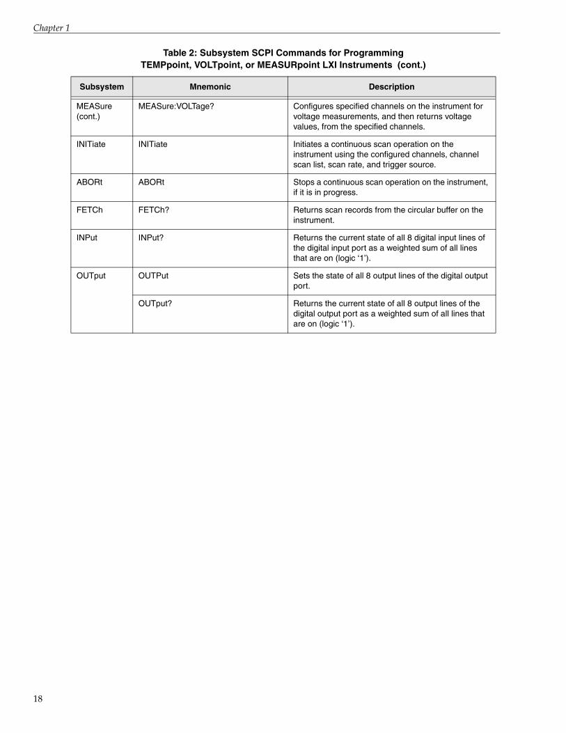
Table 2 summarizes the SCPI commands and queries available for programming each subsystem of a TEMPpoint, VOLTpoint, or MEASURpoint LXI instrument. Refer to Chapter 4 starting on page 65 for a detailed description of these commands.

Syntax Conventions
Table 2: Subsystem SCPI Commands for Programming TEMPpoint, VOLTpoint, or MEASURpoint LXI Instruments
Subsystem Mnemonic Description
STATus STATus:OPERation[:EVENt]? Has no effect on TEMPpoint, VOLTpoint, and MEASURpoint LXI instruments.
STATus:OPERation:CONDition? Returns the current value of the Operation Status register, described on page 174.
STATus:OPERation:ENABle Has no effect on TEMPpoint, VOLTpoint, and MEASURpoint LXI instruments.
STATus:OPERation: ENABle? Always returns 0 for TEMPpoint, VOLTpoint, and MEASURpoint LXI instruments.
STATus:PRESet Has no effect on TEMPpoint, VOLTpoint, and MEASURpoint LXI instruments.
STATus:QUEStionable[:EVENt]? Always returns 0 for TEMPpoint, VOLTpoint, and MEASURpoint LXI instruments.
STATus:QUEStionable:CONDition? Always returns 0 for TEMPpoint, VOLTpoint, and MEASURpoint LXI instruments.
STATus:QUEStionable:ENABle Has no effect on TEMPpoint, VOLTpoint, and MEASURpoint LXI instruments.
STATus:QUEStionable:ENABle? Always returns 0 for TEMPpoint, VOLTpoint, and MEASURpoint LXI instruments.
STATus:SCAn? Returns the indices of the chronologically oldest and most recent scan records in the circular buffer on the instrument.
SYSTem SYSTem:BOArd[:NUMber]? Returns the number of boards currently installed in the instrument.
SYSTem:BOArd:MODel? Returns the model number corresponding to a specific board in the instrument.
SYSTem:BOArd:MODel:NAMe? Returns the model name of a specific board in the instrument.
SYSTem:BOArd:RANGe? Returns the minimum and maximum voltages that are supported by a specific board in the instrument.
SYSTem:CHANnel? Returns a list of analog input channels that are supported by the instrument.
SYSTem:CHANnel:RTD? Returns a list of analog input channels on the instrument that support RTD measurements.
15

Chapter 1
16
SYSTem (cont.)
SYSTem:CHANnel:TC? Returns a list of analog input channels on the instrument that support thermocouple measurements.
SYSTem:CHANnel:VOLTage:RANGe?
Returns a list of analog input channels on the instrument that support programmable voltage ranges.
SYSTem:DINput? Returns the number of digital input lines that are supported by the instrument.
SYSTem:DOUTput? Returns the number of digital output lines that are supported by the instrument.
SYSTem:SCAn:RATe:MAX? Returns the maximum scan rate or scan frequency that is supported by the instrument.
SYSTem:SCAn:RATe:MIN? Returns the minimum scan rate or scan frequency that is supported by the instrument.
SYSTem:CALibrate Auto-calibrates (auto-zeros) all input channels on the instrument.
SYSTem:DATE? Returns the current date of the instrument.
SYSTem:TIME? Returns the current time of the instrument.
SYSTem:TZONe Sets the time zone currently used by the instrument, as an offset from GMT.
SYSTem:ERRor? Reads error message from the error queue and then removes it from the queue.
SYSTem:ERRor:COUNt? Queries the error queue for the number of unread items and returns the count.
SYSTem:VERSion? Returns the SCPI version number to which the instrument complies.
SYSTem:PRESet Sets the LAN configuration to default values.
SYSTem:COMMunicate:NETwork:IPADdress?
Returns the static IP address currently used by the instrument on the network.
SYSTem:COMMunicate:NETwork:MASk?
Returns the static subnet mask currently used by the instrument on the network.
CONFigure CONFigure:RESistance Configures specified analog input channels on the instrument for resistance measurements.
CONFigure:TEMPerature:RTD Configures specified analog input channels on the instrument for RTD temperature measurements.
CONFigure:TEMPerature:TCouple Configures specified analog input channels on the instrument for thermocouple temperature measurements using the specified thermocouple type.
CONFigure:VOLTage Configures specified analog input channels on the instrument for voltage measurements.
Table 2: Subsystem SCPI Commands for Programming TEMPpoint, VOLTpoint, or MEASURpoint LXI Instruments (cont.)
Subsystem Mnemonic Description

Syntax Conventions
CONFigure (cont.)
CONFigure:VOLTage:RANGe Configures the voltage range for specified analog input channels on the instrument.
CONFigure? Returns the configuration of specified analog input channels on the instrument.
CONFigure:FILTer Configures the filter type used for analog input operations on the instrument.
CONFigure:FILTer? Returns the currently configured filter type used for analog input operations on the instrument.
CONFigure:SCAn:BUFfer Returns the size of the circular buffer, in bytes, that is used to store scan data.
CONFigure:SCAn:CJC Enables the capability of returning CJC data in the analog input data stream.
CONFigure:SCAn:CJC? Returns whether the capability of returning CJC data in the analog input data stream has been enabled or disabled.
CONFigure:SCAn:LISt Enables a list of channels to scan on the instrument.
CONFigure:SCAn:LISt? Returns the list of channels that are enabled for scanning on the instrument.
CONFigure:SCAn:RATe Configures either the time period of each scan, in the number of seconds per scan, or the scan frequency, in Hertz.
CONFigure:SCAn:RATe? Returns either the time period of each scan, in the number of seconds per scan, or the scan frequency, in Hertz.
CONFigure:TRIGger[:SOURce] Configures the trigger source that starts the analog input operation on the instrument once the INITiate command is executed.
CONFigure:TRIGger[:SOURce]? Returns the currently configured trigger source that starts the analog input operation on the instrument once the INITiate command is executed.
MEASure MEASureRESistance? Configures specified channels on the instrument for resistance measurements, and then returns resistance values, in ohms, from the specified channels.
MEASure:TEMPerature:RTD? Configures specified channels on the instrument for RTD measurements, and returns temperature values, in degrees C, from the specified channels.
MEASure:TEMPerature:TCouple? Configures specified channels on the instrument for thermocouple measurements, and returns temperature values, in degrees C, from the specified channels.
Table 2: Subsystem SCPI Commands for Programming TEMPpoint, VOLTpoint, or MEASURpoint LXI Instruments (cont.)
Subsystem Mnemonic Description
17
Chapter 1
18
MEASure (cont.)
MEASure:VOLTage? Configures specified channels on the instrument for voltage measurements, and then returns voltage values, from the specified channels.
INITiate INITiate Initiates a continuous scan operation on the instrument using the configured channels, channel scan list, scan rate, and trigger source.
ABORt ABORt Stops a continuous scan operation on the instrument, if it is in progress.
FETCh FETCh? Returns scan records from the circular buffer on the instrument.
INPut INPut? Returns the current state of all 8 digital input lines of the digital input port as a weighted sum of all lines that are on (logic ‘1’).
OUTput OUTPut Sets the state of all 8 output lines of the digital output port.
OUTput? Returns the current state of all 8 output lines of the digital output port as a weighted sum of all lines that are on (logic ‘1’).
Table 2: Subsystem SCPI Commands for Programming TEMPpoint, VOLTpoint, or MEASURpoint LXI Instruments (cont.)
Subsystem Mnemonic Description

Syntax Conventions
Syntax of Program MessagesA program message consists of one or more properly formatted SCPI commands sent from the controller to the instrument to request some action or to query the instrument for a response.
Figure 1 shows the syntax of a program message:
Figure 1: Syntax of Program Messages
A semicolon ( ; ) is used to separate commands within the same command group, and can also minimize typing. For example, you could send the following program message to set the state of the digital output port (all 8 digital output lines) and read the status of the digital output lines:
:OUTPut:255; :OUTput?
Use a semicolon and a colon to link commands from different groups. For example, this program message returns the contents of the Operation Status register, and then sets the state of the digital output port:
:STATus:OPERation:CONDition? ;:OUTPut:255
To terminate a program message, use one of the following program message terminators:
• <newline> or the <NL> character
• <^END>
<^END> means that the IEEE-488 EOI (End-Or-Identify) message was asserted at the same time that the last data byte was sent. <^END> is interpreted as a <NL> character and can be used to terminate a command string in place of a <NL> character.
• <newline><^END>
Terminating the program message always resets the current SCPI command path to the root level.
The following subsections describe the syntax of both the common SCPI commands and the subsystem SCPI commands.
19

Chapter 1
20
Syntax of Common SCPI Commands
Figure 2 shows the syntax of common SCPI commands.
Figure 2: Syntax of Common SCPI Commands
Common SCPI commands begin with an asterisk (*). The command mnemonic is case-insensitive. For example, the following commands have the same effect:
*RST*rst*Rst
Queries requires a question mark (?) at the end of the command header, as follows:
*IDN?
Syntax of SCPI Subsystem Commands
Figure 3 shows the syntax of SCPI subsystem commands.
Figure 3: Syntax of SCPI Subsystem Commands

Syntax Conventions
Use a colon ( : ) to separate command keywords or mnemonics, as shown below:
:STATus:OPERation:ENABle
Queries require a question mark (?) at the end of the command header, as follows:
:STATus:OPERation:CONDition?
About Short- and Long-Form Mnemonics
Note that the command syntax shows most command mnemonics (and some parameters) as a mixture of upper- and lower-case letters. The upper-case letters indicate the abbreviated spelling for the command. For shorter program lines, use the abbreviated form; for better program readability, use the long form.
You can use either upper- or lower-case letters to specify the command, as the mnemonic is case-insensitive. For example, here is the long form of a command:
SYSTem:COMMunicate:NETwork:MASk?
And, here is the short-form of this command:
Syst:Comm:NET:Mas?
About Brackets, Braces, and Vertical Bars
Some parameters are enclosed in square brackets ( [ ] ), indicating that the parameter is optional and can be omitted. The brackets are not sent with the command. If you do not specify a value for an optional parameter, the instrument uses a default value.
Triangle brackets ( < > ) indicate that you must specify a value for the enclosed parameter. The brackets are not sent with the command.
Braces ( { } ) enclose the parameter choices for a given command. The braces are not sent with the command.
A vertical bar ( | ) separates multiple parameter choices for a given command.
21

Chapter 1
22
Syntax of Response MessagesA response message consists of data in a specific SCPI format that was requested from the instrument by the controller.
Figure 4 shows the syntax of a response message from the instrument:
Figure 4: Response Message Syntax
Response messages may contain both commas (,) and semicolons (;) as separators. When a single query command returns multiple values, a comma is used to separate each data item. When multiple queries are sent in the same message, the groups of data items corresponding to each query are separated by semicolons.
The terminator for a response message is always <newline><^END>.
Note: For character data types in response messages, only the short-form of the mnemonic is returned in all uppercase letters.

Syntax Conventions
SCPI Data TypesSCPI defines several different data types for use in program messages sent to an instrument and in response messages received from an instrument.
TEMPpoint, VOLTpoint, and MEASURpoint LXI instruments use the following subset of SCPI data types:
• Character
• String
• <NR1>
• <NR2>
• <NRr>
• <NRf>
• <Boolean>
• <Block>
This section summarizes these data types. Refer to the SCPI standards document for more information about these data types.
Character Data Types
If a command parameter takes a character data type, a specific number of settings are allowed for the parameter. For example, in the following command, you can specify one of the following character data types: TCouple for thermocouple measurements, RTD for RTD measurements, or DEFault for the default configuration for the instrument type:
:CONFigure:TEMP {TCouple|RTD|DEFault}
Character data types have the following characteristics:
• Can have either the short or long form in program messages and are returned in short-form only in response messages
• Are case insensitive in program messages and are in uppercase only in response messages
• Must have a specific length
String Data Types
Strings used in command parameters and responses follow these rules:
• Strings are enclosed in double quotes " "For example,
"This is an example"
specifies the following string: This is an example
23

Chapter 1
24
• Use double quotes within double quotes to indicate the part of the string that should appear in quotes; note that double and single quotes used inside the string must be duplicated. For example,
"This is the ""example""
specifies the following string: This is the “example”
• ? Strings are case sensitive
<NR1>Value Data Type
The <NR1> value data type is used to specify zero, and positive and negative integer decimal values, including optional signs. If you need to indicate decimal points, use the <NR2> value data type, instead.
The following values are examples of the <NR1> data type:
0 255 –2
<NR2> Value Data Type
The <NR2> value data type is used to specify zero, and positive and negative decimal values, including optional signs and decimal points.
The difference between <NR1> and <NR2> is the explicit decimal point. Note that 0 is a special case and redundant decimal points are ignored.
The following values are examples of the <NR2> data type:
–1.234 1.0 0.0
<NRr>Value Data Type
The <NRr> data type is used to specify a non-decimal numeric value, such a hexadecimal, octal, or binary numeric value.
Figure 5 shows the format of the <NRr> data type:

Syntax Conventions
Figure 5: <NRr>Value Data Type
The following examples show how the number 16384 in decimal format is represented as a <NRr> data type:
• Hexadecimal <NRr> value: #H4000
• Octal <NRr> value: #Q40000
• Binary <NRr> value: #B100000000000000
<NRf>Value Data Type
The <NRf> data type is used to specify a floating-point value. These values include digits with an implied decimal point, an explicit decimal point, or an explicit decimal point and an exponent.
The following values are examples of the <NRf> data type:
6553 1.525e-4 0.100000
Octal
Hexadecimal
Binary
25

Chapter 1
26
<Boolean> Data Type
A Boolean data type for a parameter and response represents a single binary condition that is either True or False. Boolean values are defined as follows:
• 0 or OFF – indicates that the condition is False
• 1 or ON – indicates that the condition is True
Note that the characters OFF and ON are not case sensitive. While a TEMPpoint, VOLTpoint, or MEASURpoint LXI instrument accepts the characters OFF and ON instead of 0 and 1, if queried, these instruments return Boolean responses as either 0 or 1.
<Block> Data Type
The <Block> data type is used to transfer array and system-defined blocks of data between the controller and the instrument. This is the most efficient data format for transferring data.
Figure 6 shows the format of the <Block> data type:
Figure 6: Block Data Type
where:
• # is the starting character of the block
• <non-zero digit> is a single decimal value that specifies how many digits will follow in the next field
• <digit> is a value in <NR1> format that specifies how many <8-bit data byte>s follow. In effect, this field specifies the length, in bytes, of the remainder of the block.
• <8-bit data byte> specifies each 8-bit byte of the block. (The number of 8-bit data bytes is specified in the preceding field. ) The contents of this block of bytes is dependent on the specific command.
Note: Prior to interpreting multi-byte values, such as floats, integers, unsigned integers, and so on, you must convert values from network-byte-order (where the highest bytes are sent first; i.e., big-endian) to host-byte-order (where the lowest bytes are read first, i.e., little endian).
The following example shows how a block of five data bytes is formatted:
#1<5><b0><b1><b2><b3><b4>
Syntax Conventions
SCPI Expression TypesSCPI defines five types of expressions:
• Numeric expressions
• Channel lists
• Numeric lists
• Data Interchange Format (DIF) expressions
• Instrument-specifier expressions
The following subsections summarize these expressions. Refer to the SCPI standard document for more information about these expressions.
Numeric Expressions
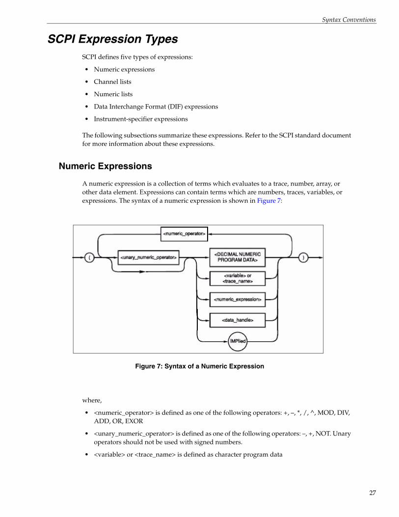
A numeric expression is a collection of terms which evaluates to a trace, number, array, or other data element. Expressions can contain terms which are numbers, traces, variables, or expressions. The syntax of a numeric expression is shown in Figure 7:
Figure 7: Syntax of a Numeric Expression
where,
• <numeric_operator> is defined as one of the following operators: +, –, *, /, ^, MOD, DIV, ADD, OR, EXOR
• <unary_numeric_operator> is defined as one of the following operators: –, +, NOT. Unary operators should not be used with signed numbers.
• <variable> or <trace_name> is defined as character program data
27

Chapter 1
28
Expressions are evaluated according to the following precedence rules:
1. Enclosed by parentheses
2. Unary operators (+ and -)
3. ^(exponentiation)
4. * (multiplication), / (division), MOD and DIV
5. + (addition) and - (subtraction)
6. NOT
7. AND
8. OR and EXOR
9. Left to right
Elements in a numeric expression are promoted to the size and type of the most complex element, and the result of the expression is of that type. For example, an expression containing a <trace_name>is evaluated according to the rules for arithmetic on traces, and the result is a trace. If an expression contains both a <trace_name> and scalar data, a trace is created with all elements set to the value of the scalar data before arithmetic is performed. For example, if TREF is a trace_name, the expression (TREF-3) results in a trace that is the same size as TREF, with each data element lower by three.
Channel Lists
TEMPpoint, VOLTpoint, and MEASURpoint LXI instruments use channel lists as parameters in certain commands and in responses to certain queries.
Channel lists are used to specify the analog input channels that are used to measure a combination of either thermocouple, voltage, or RTD inputs. A channel list may appear in a measurement, configuration, or command. By design, all analog input channels that are specified in the channel list are measured simultaneously.
The syntax of a channel list expression is shown in Figure 8:
Figure 8: Syntax of a Channel List Expression

Syntax Conventions
where:
• ( is the starting character of the channel list
• @ is the next character of the channel list
• <channel range> consists of two channels in <NR1> format separated by a colon.
For TEMPpoint, VOLTpoint, and MEASURpoint instruments, the number of channels ranges from 0 up to 48, depending on the configuration of your instrument. The first channel in the range must be lower than the second in the range.
Separate multiple <channel_range> elements with commas.
• <channel> consists of one channel number in < NR1> format. For TEMPpoint, VOLTpoint, and MEASURpoint instruments, this is a number from 0 to 48, depending on the configuration of your instrument. Separate multiple <channel> elements with commas.
• ) terminates the channel list expression
For example, to measure the voltage on analog input channels 4 through 6, use one of the following commands:
MEAS:VOLT? (@4:6)
MEAS:VOLT? (@4,5,6)
To measure the voltage of analog input channel 4 only, use this command:
MEAS:VOLT? (@4)
Numeric Lists
A numeric list is a an expression format for compactly expressing numbers and ranges of numbers in a single parameter. The syntax of a numeric list expression is shown in Figure 9:
Figure 9: Syntax of Numeric List Expressions
where:
• <NRf> is an extended format, described on page 25.
• <numeric_range> is defined as two <NRf> data types separated by colons. The range is inclusive of the specified numbers.
29

Chapter 1
30
Data Interchange Format (DIF) Expressions
The data interchange format is block-structured and lets software packages and instruments share waveform and other data.
The following block types are available in DIF expressions:
• DATA block – Contains the data.
• IDENtify block – Describes the manner and environment in which the data was obtained.
• DIMension, ORDer, and ENCode blocks – Describe how the data is physically represented and logically organized.
• TRACe and VIEW blocks – Provide semantic information about the data.
• REMark block – Contains textual comments regarding the data.
• DIF block – Identifies the block as a <dif_expression> and describes the version of SCPI that is used.
In a DIF expression, each hierarchical level of a block is introduced by a block name with its subordinate elements enclosed in parentheses. A block may have a modifier and may contain subordinate blocks and keyword units, or both. Keyword units consist of a keyword followed by one or more values. If a keyword has more than one value, the values are separated by commas. The following example shows a simple data set. All blocks and keywords are indented to show their hierarchical relationship:
(DIF (VERSion 1993.0)IDENtify (
NAME "Data Format Example"TEST (
NUMBer "7D4", "2.4"))ENCode (
HRANge 75RANge 25)
DIMension=X (TYPE IMPLicitSCALe 0.01SIZE 7UNITs "S")
DIMension=Y (TYPE EXPLicitSCALe 0.02OFFSet 0.1UNITs "V")
DATA ( CURVe(
VALues 49.0, 48.0, 50.2, 61.3, 68.5, 38.6, 48.0)))
The data interchange format overall is formatted as an IEEE 488.2 <EXPRESSION PROGRAM DATA> element. Within this element, the various blocks, modifiers, keywords, and value types are composed of syntactic elements that, for the most part, are identical to the corresponding types specified in IEEE 488.2 or a subset of them. Refer to the IEEE 488.2 standard for more information.

Syntax Conventions
Instrument-Specifier Expressions
An <instrument_specifier> is a combination of one or more base functionality keywords along with optional additional functionality keywords that define an instrument class. The syntax of an instrument-specifier expression is shown in Figure 10.
Figure 10: Syntax of an Instrument-Specifier Expression
where:
• ( is the starting character of the instrument-specifier expression
• <and_or_operator> is either ‘&’ (ASCII hexadecimal 26) or ‘|’ (ASCII hexadecimal 7C)
• <bf_keyword> is a base functionality keyword
• <af_expression> includes additional <and_or_operator>s and additional functionality keywords
• ) terminates the instrument-specifier expression
31

Chapter 1
32

2Using SCPI Commands with LXI
Measurement InstrumentsInstalling SCPI Support Files . . . . . . . . . . . . . . . . . . . . . . . . . . . . . . . . . . . . . . . . . . . . . . . . . . . 34
Performing Analog Input Operations . . . . . . . . . . . . . . . . . . . . . . . . . . . . . . . . . . . . . . . . . . . . 41
Performing Digital Input Operations . . . . . . . . . . . . . . . . . . . . . . . . . . . . . . . . . . . . . . . . . . . . 53
Performing Digital Output Operations. . . . . . . . . . . . . . . . . . . . . . . . . . . . . . . . . . . . . . . . . . . 54
33

Chapter 2
34
Installing SCPI Support FilesInstall the SCPI support files and the rest of the software for your instrument from the web at http://mccdaq.com/downloads/DTSoftware/MEASURpoint.
The installation program guides you through the installation process.
To access the SCPI documentation and examples, from the Windows Start menu, click Programs -> Data Translation, Inc -> Measurement SCPI Support -> SCPI Programmer’s Manual for Measurement

Using SCPI Commands with LXI Measurement Instruments
Determining the LAN Settings of Your InstrumentThe Ethernet address of a TEMPpoint, VOLTpoint, or MEASURpoint instrument consists of three parts:
• The IP address – The “Internet Protocol” numeric address that identifies where messages are sent or received on the LAN (Local Area Network).
• Subnet mask – A 32-bit value that enables the recipient of IP packets to distinguish the network ID and host ID portions of the IP address.
• Gateway address –The address of the network router that allows the instrument to communicate outside of the local subnet.
The instrument can acquire an Ethernet address in one of the following ways:
• DHCP (Dynamic Host Configuration Protocol server) – The address is set by the network server automatically when the instrument is powered on. The address is different each time the instrument is powered on.
By default, DHCP is enabled for TEMPpoint, VOLTpoint, and MEASURpoint instruments.
• Auto-IP – If the DHCP server is not available, the instrument configures its own IP address in the range of 169.254.0.0 to 169.254.255.255 with a subnet mask of 255.255.0.0. Like with DHCP, the address is different each time the instrument is powered on.
By default, Auto-IP is enabled for TEMPpoint, VOLTpoint, and MEASURpoint instruments.
• Static IP – Using the web interface provided with the instrument, you can specify the static IP address of the instrument. The static IP address does not change when the instrument is powered on. Refer to the documentation for your instrument for more information about configuring a static IP address.
Using SCPI queries, you can return the following information about each TEMPpoint, VOLTpoint, and MEASURpoint instrument on the LAN:
• IP address – Use the SYSTem:COMMunicate:NETwork:IPADdress? query, described on page 80, to return the IP address of the instrument, regardless of the method (DHCP, Auto-IP, static IP) used to acquire the address.
• Subnet mask – Use the SYSTem:COMMunicate:NETwork:MASk? query, described on page 80, to return the subnet mask of the instrument, regardless of the method (DHCP, Auto-IP, static IP) used to acquire the subnet mask.
To restore the default LAN settings to their factory default values, use the SYSTem:PRESet command, described on page 80. The factory default configuration enables both DHCP and Auto-IP and disables static IP.
35

Chapter 2
36
Using Password-Protected CommandsTEMPpoint, VOLTpoint, and MEASURpoint instruments implement authentication using a single, user-configurable password. The password is saved in permanent memory in the instrument.
Note: The instrument’s web interface, IVI-COM driver, and SCPI interface use the same password.
On power up, all SCPI commands and queries that either change the configuration of the instrument or operate it are disabled. This is to prevent unauthorized access to an instrument by some client on the network.
By using the SYSTem:PASSword[:CENable] command, described on page 83, you can enable password-protection. When password protection is enabled, the correct password must be issued to use the following SCPI commands:
• OUTPut[:STATe], described on page 151
• CONFigure:VOLTage, described on page 109
• CONFigure:RESistance, described on page 103
• CONFigure:TEMPerature:TCouple, described on page 106
• CONFigure:TEMPerature:RTD, described on page 104
• CONFigure:VOLTage:RANGe, described on page 111
• CONFigure:SCAn:LISt, described on page 120
• CONFigure:SCAn:CJC, described on page 118
• CONFigure:SCAn:RATe[:SEC|HZ], described on page 123
• CONFigure:FILTer, described on page 115
• CONFigure:TRIGger[:SOURce], described on page 127
• INITiate, described on page 140
• ABORt, described on page 143
• MEASure:VOLTage?, described on page 137
• MEASure:RESistance?, described on page 130
• MEASure:TEMPerature:TCouple?, described on page 134
• MEASure:TEMPeratuer:RTD?, described on page 131
• SYSTem:TZONe, described on page 100
• SYSTem:CALibrate, described on page 77
To disable the use of password-protected commands, use the SYSTem:PASSword:CDISable command, described on page 81.

Using SCPI Commands with LXI Measurement Instruments
You can determine whether password-protected commands are disabled or enabled using the SYSTem:PASSword:CENable:STATe? command, described on page 85.
The default password is admin for all TEMPpoint, VOLTpoint, and MEASURpoint instruments.
Note: The DT8871, DT8871U, DT8872, DT8873, and DT8874 instruments with firmware version 2.2.3.1 or greater use the default user name "admin" and the default password "admin". Firmware version 2.2.3.1 and greater support password-protected commands. Therefore, you must enter the appropriate password to change the instrument’s configuration or to start and stop a scan.
Firmware versions less than 2.2.3.1 do not support password-protected commands. Therefore, you are not prompted to enter a password to change the instrument’s configuration or to start or stop a scan.
You change the password from the current password that is stored in permanent memory in the instrument to a new password using the LAN configuration page of the web interface for the instrument, through the IVI-COM driver, or through the SCPI command SYSTem:PASSword:NEW, described on page 86.
A SCPI client that wishes to configure and/or operate a TEMPpoint, VOLTpoint, or MEASURpoint instrument should use these commands as follows:
1. Use the query :SYSTem:PASSword:CENable:STATe? to determine if password-protected commands are enabled.
The following example shows that password-protected commands are disabled:
-> *IDN?<- Data Translation, DT8874-08T-00R-08V,201129241,2.2.2.0-> :SYSTem:PASSword:CENable:STATe?<- 0
2. If password-protected commands are disabled, enable password-protected commands by using SYSTem:PASSword:CENable. If this command is successful, the client can configure the instrument and operate it. An example follows:
-> :SYST:PASS:CEN admin-> :SYSTem:PASSword:CENable:STATe?<- 1-> :CONF?<- PT1000,PT1000,PT1000,PT1000-> :CONF:TEMP:RTD PT100-> :CONF?<- PT100,PT100,PT100,PT100
3. If this command is successful, the client can configure the instrument and start scans.
4. To prevent some other SCPI client, locally or on the LAN, from stopping the scan and modifying the configuration, the client that enabled password-protected commands should issue SYSTem:PASSword:CDISable.
37

Chapter 2
38
The following example shows an attempt to disable protected commands using an erroneous password:
-> :SYSTem:PASSword:CDISable bogus-> :SYST:ERR?<- -221,"Settings conflict;:SYST:PASS:CDIS"
The following is an example in which the correct password is used to disable protected commands:
-> :SYSTem:PASSword:CDISable admin-> :SYST:ERR?<- 0,"No error"-> :SYSTem:PASSword:CENable:STATe?<- 0
Since protected commands are disabled, any attempt to use them will fail, as shown in the following example:
-> :CONF?<- PT1000,PT1000,PT1000,PT1000-> :CONF:TEMP:RTD PT1000-> :SYST:ERR?<- -203,"Command protected"-> :CONF?<- PT1000,PT1000,PT1000,PT1000-> *STB?<- 0-> :INIT-> :SYST:ERR?<- -203,"Command protected"-> *STB?<- 0
In this scenario, one “master” SCPI client can configure the instrument, start scans, and disable SCPI commands. Since all queries are permitted regardless of the state of password protection, any client can perform FETCh? and other queries. The "master" can eventually enable password-protected commands and stop scans. The password should not be shared and should only be known by the master SCPI client.
5. At any time, the password can be changed using SYSTem:PASSword:NEW. Note that this command is never disabled.
The following example shows an attempt to change the password using a wrong password:
-> :SYST:PASS:NEW bogus, admin1-> :SYST:ERR?<- -221,"Settings conflict;:SYST:PASS:NEW"
In the following example, the existing password admin is successfully changed to admin1:
-> :SYST:PASS:NEW admin, admin1-> :SYST:ERR?<- 0,"No error"

Using SCPI Commands with LXI Measurement Instruments
The following example shows that the old password admin is no longer in use and the new password admin1 is in effect:
-> :SYSTem:PASSword:CDISable admin-> :SYST:ERR?<- -221,"Settings conflict;:SYST:PASS:CDIS"-> :SYSTem:PASSword:CDISable admin1-> :SYST:ERR?<- 0,"No error"-> :SYSTem:PASSword:CENable:STATe?<- 0
39

Chapter 2
40
Determining the System ConfigurationEach of the standard TEMPpoint, VOLTpoint, and MEASURpoint products consists of up to eight boards, each with eight channels, for a total of up to 48 channels.
Instruments may be composed of multiple board types/models. For example, a DT8874-24T-08R-16V, contains thermocouple boards, RTD boards, and voltage input boards. To determine programmatically which boards comprise your TEMPpoint, VOLTpoint, or MEASURpoint instrument, use the following SCPI queries:
• SYSTem:BOArd? – Returns the number of boards installed in the instrument.
• SYSTem:BOArd:MODel? – Returns a number that corresponds to a particular board in the instrument. The following values are supported:
− 0 – DT8771 (This is a thermocouple board.)
− 1 – DT8871U (This is a thermocouple board.)
− 2 – DT8873-100V (This is a voltage board with a fixed range of ±100 V; this is an olderboard model that has been replaced by the DT8873-MULTI board type.)
− 3 – DT8873-10V (This is a voltage board with a fixed range of ±10 V. This is an olderboard model that has been replaced by the DT8873-MULTI board type.)
− 4 – DT8873-400V (This is a voltage board with a fixed range of ±400 V. This is an olderboard model that has been replaced by the DT8873-MULTI board type.)
− 5 – DT8872 (This is an RTD board.)
− 7 – DT8873-MULTI (This is a voltage board that supports programmable voltageranges of ±10 V and ±60 V.)
• SYSTem:BOArd:MODel:NAMe? – Returns the name that corresponds to a particular board in the instrument. The following names are supported:
− DT8771 (This is a thermocouple board.)
− DT8871U (This is a thermocouple board.)
− DT8873-100V (This is a voltage board with a fixed range of ±100 V. This is an older board type that has been replaced by the DT8873-MULTI board type.)
− DT8873-10V (This is a voltage board with a fixed range of ±10 V. This is an older board type that has been replaced by the DT8873-MULTI board type.)
− DT8873-400V (This is a voltage board with a fixed range of ±400 V. This is an olderboard type that has been replaced by the DT8873-MULTI board type.)
− DT8872 (This is an RTD board.)
− DT8873-MULTI (This is a voltage board that supports programmable voltage ranges of ±10 V and ±60 V.)
You can also return the minimum and maximum voltage range that is supported by each board using the SYSTem:BOArd:RANGe? command.
Using SCPI Commands with LXI Measurement Instruments
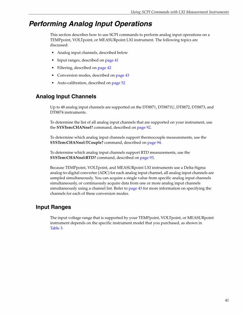
Performing Analog Input OperationsThis section describes how to use SCPI commands to perform analog input operations on a TEMPpoint, VOLTpoint, or MEASURpoint LXI instrument. The following topics are discussed:
• Analog input channels, described below
• Input ranges, described on page 41
• Filtering, described on page 42
• Conversion modes, described on page 43
• Auto-calibration, described on page 52
Analog Input Channels
Up to 48 analog input channels are supported on the DT8871, DT8871U, DT8872, DT8873, and DT8874 instruments.
To determine the list of all analog input channels that are supported on your instrument, use the SYSTem:CHANnel? command, described on page 92.
To determine which analog input channels support thermocouple measurements, use the SYSTem:CHANnel:TCouple? command, described on page 94.
To determine which analog input channels support RTD measurements, use the SYSTem:CHANnel:RTD? command, described on page 93.
Because TEMPpoint, VOLTpoint, and MEASURpoint LXI instruments use a Delta-Sigma analog-to-digital converter (ADC) for each analog input channel, all analog input channels are sampled simultaneously. You can acquire a single value from specific analog input channels simultaneously, or continuously acquire data from one or more analog input channels simultaneously using a channel list. Refer to page 43 for more information on specifying the channels for each of these conversion modes.
Input Ranges
The input voltage range that is supported by your TEMPpoint, VOLTpoint, or MEASURpoint instrument depends on the specific instrument model that you purchased, as shown in Table 3.
41

Chapter 2
42
VOLTpoint and MEASURpoint instruments provide channels with software-selectable voltage ranges. To determine which channels support programmable voltage ranges, use the SYSTem:CHANnel:VOLTage:RANGe? query.
You can set the input voltage range for these channels using the CONFigure:VOLTage:RANGe command. By default, these channels are configured to use ±10 V range.
Use the CONFigure? command to determine the current configuration of each channel.
Filtering
Each Delta-Sigma A/D converter provided for analog input operations on the TEMPpoint, VOLTpoint, or MEASURpoint LXI instrument provides a filter that rejects noise at 50 Hz and 60 Hz and removes aliasing, a condition where high frequency input components erroneously appear as lower frequencies after sampling.
In addition to this filter, you can further reduce noise by selecting one of the following software filters using the CONFigure:FILTer command:
• RAW – No filter. Provides fast response times, but the data may be difficult to interpret. Use when you want to filter the data yourself.
The RAW filter type returns the data exactly as it comes out of the Delta-Sigma A/D converters. Note that Delta-Sigma converters provide substantial digital filtering above the Nyquist frequency.
Generally, the only time it is desirable to turn off the software filter is if you are using fast responding thermocouples/RTDs, sampling them at higher speeds (> 1 Hz), and need as much response speed as possible.
Table 3: Supported Input Ranges
Instrument Type Models Input Range
TEMPpoint DT8871Ua
a. Instruments with firmware version 2.2.3.1 or greater are identified in firmware as DT8874-xxT-xxR-xx-V, where xxT specifies the number of thermocouple channels, xxR specifies the number of RTD channels, and xxV specifies the number of voltage input channels.
±0.75 V for all channels
DT8871a ±1.25 V for all channels
DT8872a ±1.25 V for all channels
VOLTpoint DT8873a ±10 V or ±60 V (software-selectable for each channel)b
b. Older versions of this instrument had fixed input ranges of ±10 V, ±100 V, or ±400 V, depending on the model purchased.
MEASURpoint DT8874-xxT-xxR-xxV ±0.75 V for thermocouple channels;±1.25 V for RTD channels; ±10 V or ±60 V for voltage channels (software-selectable for each channel)b
Using SCPI Commands with LXI Measurement Instruments
• AVG – The Moving Average filter provides a compromise of filter functionality and response time. This filter can be used in any application.
This low-pass filter takes the previous 16 samples, adds them together, and divides by 16.
You can query the current filter configuration using the CONFigure:FILTer? query.
Conversion Modes
TEMPpoint, VOLTpoint, and MEASURpoint LXI instruments support simultaneous single-value and continuous scan conversion modes for acquiring data from analog input channels.
In addition, these instrument allows you to read the digital input port (all 8 digital input lines) as part of the analog input data stream. This feature is particularly useful when you want to correlate the timing of analog and digital events.
This section describes each of these conversion modes.
Simultaneous Single-Value Operations
If you want a snapshot of specific analog input channels on a TEMPpoint, VOLTpoint, or MEASURpoint LXI instrument at one point in time, perform a simultaneous single-value operation. The following single-value commands configure particular analog input channels, and then simultaneously acquire a single value from each of these channels:
• MEASure:TEMPerature:TCouple? – Configures specified analog input channels for thermocouple measurements, and then returns temperature values, in degrees Celsius, from the specified channels.
• MEASure:TEMPerature:RTD? – Configures specified analog input channels for RTD measurements, and then returns temperature values, in degrees Celsius, from the specified channels.
• MEASure:RESistance? – Configures the specified analog input channels for resistance measurements, and then returns resistance values, in ohms, from the specified channels.
• MEASure:VOLTage? – Configures specified analog input channels for voltage measurements, and then returns voltage values from the specified channels.
Note: If your instrument supports programmable voltage ranges, first configure the voltage ranges using the CONFigure:VOLTage:RANGe command before calling MEASure:VOLTage?
A single-value operation stops automatically when finished; you cannot stop a single-value operation.
43

Chapter 2
44
Note: Values returned from single-value operations are based on the configured filter type, described on page 42.
In a mix-and-match configuration, it is easy to accidentally mismatch the software and hardware configuration for a channel. Therefore, it is recommended that you pay particular attention when configuring channels, since the resultant errors may be not large enough to notice initially, but may be significantly larger than the accuracy specification for the instrument.
Continuous Scan Mode
Continuous scan mode takes full advantage of the capabilities of a TEMPpoint, VOLTpoint, or MEASURpoint LXI instrument. Use continuous scan mode if you want to continuously scan a list of channels, including the analog input channels and the digital input port.
To perform a continuous scan operation, perform the following steps:
1. Configure the analog input channels that you want to sample.
2. For thermocouple measurements, optionally enable the capability of returning CJC data in the analog input data stream.
3. Specify a list of channels to scan.
4. Specify the frequency at which to scan the channel list.
5. Specify the trigger source that starts the operation once the scan is initiated.
6. Initiate the scan.
7. Retrieve scan data from the circular buffer on the instrument.
The following sections describe these steps in more detail.
Note: Values returned from continuous scan operations are based on the configured filter type, described on page 42.
Configuring Channels for a Continuous Scan Operation
Using software, configure the analog input channels that you want to sample using one of the following commands:
• CONFigure:VOLTage – For channels that do not support programmable voltage ranges, configures specific analog input channels for voltage measurements.
• CONFigure:VOLTage:RANGe – For channels that support programmable voltage ranges, configures the channel for voltage measurements and sets the input voltage range. Refer to page 41 for more information.
• CONFigure:TEMPerature:TCouple – Configures specific analog input channels for thermocouple measurements based on the specified thermocouple type.

Using SCPI Commands with LXI Measurement Instruments
• CONFigure:TEMPerature:RTD – Configures specific analog input channels for RTD measurements based on the specified RTD type.
• CONFigure:RESistance – For RTD measurements, configures specific analog input channels for resistance measurements.
Note: In a mix-and-match configuration, it is easy to accidentally mismatch the software and hardware configuration for a channel. Therefore, it is recommended that you pay particular attention when configuring channels, since the resultant errors may be not large enough to notice initially, but may be significantly larger than the accuracy specification for the instrument.
You can query the current configuration of specified analog input channels using the CONFigure? query.
Returning CJC Values in the Data Stream
Each analog input channel that supports thermocouple inputs has its own cold-junction compensation (CJC) circuit at the input. Using the CONFigure:SCAn:CJC command, you can enable the capability of returning the CJC values in the data stream.
This option is seldom used, but is provided if you want to implement your own temperature conversion algorithms in software when using continuous operations. The software takes care of correlating the CJC measurements with the analog input measurements.
Specifying a Channel List for a Continuous Scan Operation
Use the CONFigure:SCAn:LISt command to specify a channel list that contains the analog input channels that you want to scan. You can also read the value of the digital input port through the analog input data stream by specifying the digital input channel in the channel list; the number of the digital input channel depends on the configuration of your instrument, as shown in Table 4.
Table 4: Supported Channels for Continuous Operations
Instrument TypeTotal Number of
Analog Input ChannelsChannel for Reading the Digital Input Port
Standard TEMPpoint,VOLTpoint,
MEASURpoint (DT8871, DT8871U,DT8872,DT8873, DT8874)
0 to 7 8
0 to 15 16
0 to 23 24
0 to 31 32
0 to 39 40
0 to 47 48
45

Chapter 2
46
Note: You cannot specify the same channel more than once in the channel list.
If a channel is included in the channel list, the sampled data is placed in the circular buffer on the instrument (described on page 47). If the channel is not included in the channel list, the data for that channel is discarded.
Specifying the Scan Rate
Due to the simultaneous nature of TEMPpoint, VOLTpoint, and MEASURpoint LXI instruments, all channels in the list are sampled simultaneously. You specify the scan rate or frequency using the CONFigure:SCAn:RATe command.
Note: The scan rate or frequency that you specify is rounded to the closest "correct" value that the instrument can accept without error. Internally, the 10 Hz clock is divided by an integer in the range of 1 to 65535 (the internal clock divider) to determine the closest value. Using software, you can query this setting to determine the actual scan rate or frequency that is used.
To determine the minimum scan rate or frequency that is supported by your instrument use the SYSTem:SCAn:RATe:MINimum? command, described on page 98.
To determine the maximum scan rate or frequency that is supported by your instrument use the SYSTem:SCAn:RATe:MAXimum? command, described on page 97.
Specifying the Trigger Source
A trigger is an event that occurs based on a specified set of conditions. Using the CONFigure:TRIGger[:SOURce] command, you can configure one of the following trigger sources:
• IMMediate – Specifies a software trigger. When the INITiate command (described below) is executed, acquisition starts immediately. This is the default trigger source.
• DIN0 – Specifies an external, digital trigger on digital input line 0. When the INITiate command (described in the next section) is executed, acquisition does not start until the instrument detects a 3 to 28 V DC signal on digital input line 0 for at least 100 ms.
To determine the currently configured trigger source use the CONFigure:TRIGger[:SOURce]? query.
Initiating and Aborting a Continuous Scan Operation
To initiate a continuous scan operation, issue the INITiate command. When the specified trigger occurs, the instrument simultaneously samples all the analog input channels, optional CJC inputs (for thermocouple measurement channels), and the digital input port, and converts the analog inputs to temperature, resistance, or voltage based on channel
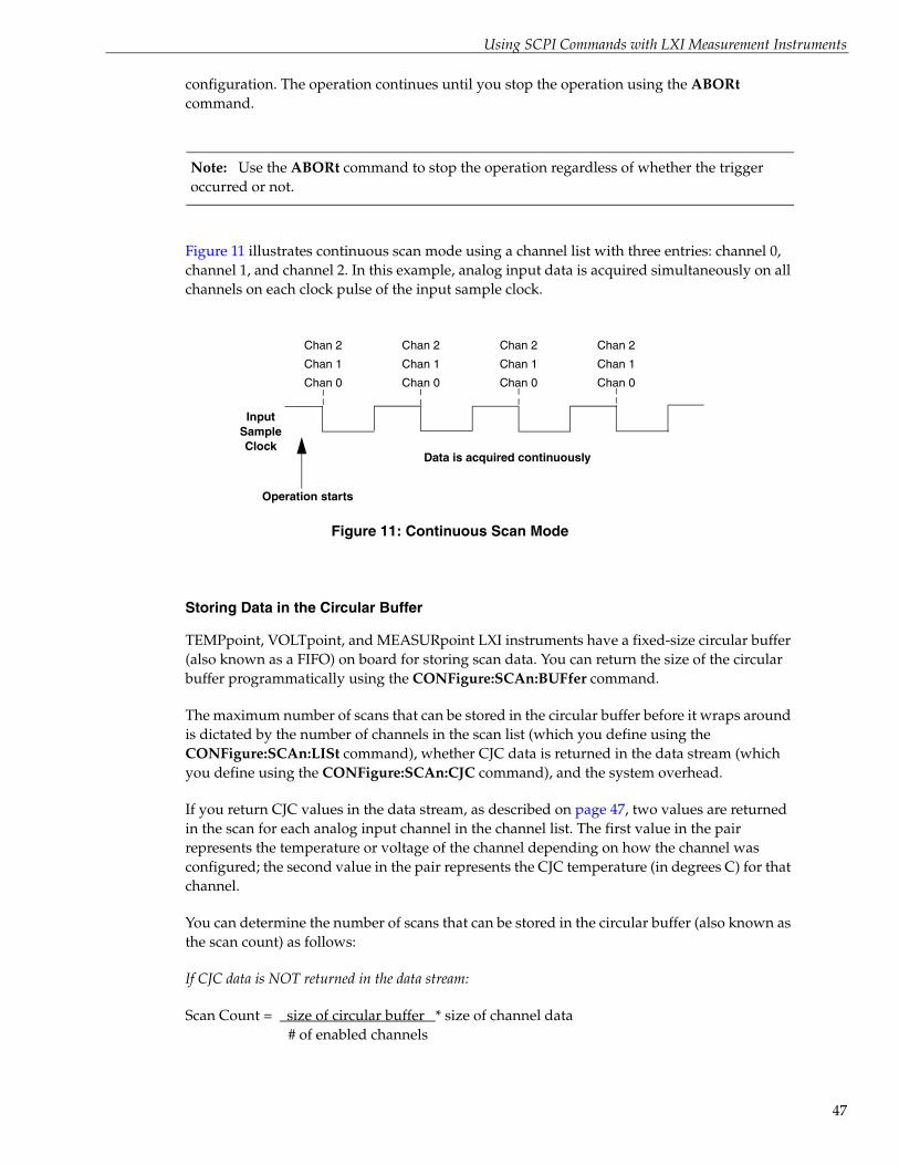
Using SCPI Commands with LXI Measurement Instruments
configuration. The operation continues until you stop the operation using the ABORt command.
Note: Use the ABORt command to stop the operation regardless of whether the trigger occurred or not.
Figure 11 illustrates continuous scan mode using a channel list with three entries: channel 0, channel 1, and channel 2. In this example, analog input data is acquired simultaneously on all channels on each clock pulse of the input sample clock.
Figure 11: Continuous Scan Mode
Storing Data in the Circular Buffer
TEMPpoint, VOLTpoint, and MEASURpoint LXI instruments have a fixed-size circular buffer (also known as a FIFO) on board for storing scan data. You can return the size of the circular buffer programmatically using the CONFigure:SCAn:BUFfer command.
The maximum number of scans that can be stored in the circular buffer before it wraps around is dictated by the number of channels in the scan list (which you define using the CONFigure:SCAn:LISt command), whether CJC data is returned in the data stream (which you define using the CONFigure:SCAn:CJC command), and the system overhead.
If you return CJC values in the data stream, as described on page 47, two values are returned in the scan for each analog input channel in the channel list. The first value in the pair represents the temperature or voltage of the channel depending on how the channel was configured; the second value in the pair represents the CJC temperature (in degrees C) for that channel.
You can determine the number of scans that can be stored in the circular buffer (also known as the scan count) as follows:
If CJC data is NOT returned in the data stream:
Scan Count = size of circular buffer * size of channel data# of enabled channels
Operation starts
Chan 0
Chan 1
Chan 2
Input Sample Clock
Data is acquired continuously
Chan 0
Chan 1
Chan 2
Chan 0
Chan 1
Chan 2
Chan 0
Chan 1
Chan 2
47

Chapter 2
48
If CJC data is returned in the data stream:
Scan Count = size of circular buffer * size of channel data* 2# of enabled channels
Figure 12 shows an example of storing 1000 scans in the circular buffer at a scan frequency of 1 Hz. A scan counter on the instrument is incremented as each scan completes.
Figure 12: Example of Storing Data in the Circular Buffer
Retrieving Scan Data from the Circular Buffer
At any instant, up to 12 SCPI clients can retrieve a client-specific number of scans concurrently from the circular buffer using the FETCh? command.
Note: Of the 12 SCPI clients, 4 can be VXI-11 clients, which use the VISA::INSTR resource to access the instrument.
Up to 8 additional clients can access the instrument concurrently using the web interface provided with the instrument. Refer to the user’s manual for your instrument for more information.
At this time, the SCPI and web interfaces cannot be "locked;" therefore, one client can change the configuration of the instrument that another client is accessing. However, you can optionally lock the VXI-11 interface using the VISA APIs viLock/viUnlock; this prevents other VXI-11 clients (including VXI-11 discovery) from accessing the instrument.
T = 0 sStart Index = 0
T = 500 sEnd Index = 500
Starting time at 0 s; buffer part full
T = 0 sStart Index = 0
Starting time at 0 s; buffer full at 1000 s
T = 1000 sEnd Index = 1000
Buffer state at time 1001 s Buffer state at time 1500 s
T = 1 sStart Index = 1
T = 1001 sEnd Index = 1001
T = 500 sStart Index = 500
T = 1500 sEnd Index = 1500

Using SCPI Commands with LXI Measurement Instruments
The FETCh? command takes two parameters:
• RequestedScansIndex – a required parameter that specifies where in the circular buffer to begin reading the scan data
• RequestedScansToRead – an optional parameter that specifies the number of scans to retrieve from the circular buffer
By using RequestedScansIndex and RequestedScansToRead, any client can request data at arbitrary intervals. To request all the data from the circular buffer, set the RequestedScansIndex to 0 and omit the RequestedScansToRead parameter.
Note that the amount of data that is return is limited by the packet size of the network. A client can repeatedly issue a FETCh? request; however, be aware that the network traffic is high and that the client has to determine if there is any chronological overlap between responses.
If you want to read only a specified number of scans (instead of all the scans available), specify the number of scans that you want to retrieve in the RequestedScansToRead parameter. If more than the requested number scans has been acquired, the instrument returns only the scans that you requested between the starting index (RequestedScansIndex) and the ending index (RequestedScansIndex + RequestedScansToRead). Conversely, if fewer than the requested number of scans has been acquired, the instrument returns the subset of the requested scans that are available between the starting index (RequestedScansIndex) and the ending index (RequestedScansIndex + RequestedScansToRead).
Scan data is stored in the circular buffer in a structure called a SCAN_RECORD. Each SCAN_RECORD structure contains time stamp information about the acquired data in millisecond granularity, the scan record number (scanNumber), the number of values in the record, and the actual samples that were acquired. Refer to page 176 for more information on the SCAN_RECORD structure.
Note: If no scan records exist between the starting index and the ending index, an empty SCAN_RECORD structure is returned.
Samples in SCAN_RECORD are ordered from the lowest channel number to the highest channel number in the scan. Reading data from the circular buffer with FETCh? does not destroy the data; therefore, you can read the same data multiple times, if desired, providing that the circular buffer has not been overwritten.
If the client wants to read a number of scans that chronologically follow a previous response, get the scanNumber of the last SCAN_RECORD, returned from the last Fetch? command, or get the EndingIndex returned by the STATus:SCAn command, described on page 74, add one to this value, and set the RequestedScansIndex parameter of the next Fetch? command to this value. For example, if EndingIndex returned by STATus:SCAn is 2050 and you want to continue reading data from the location where you left off, set RequestedScansIndex in the next Fetch? command to 2051.
Table 5 illustrates a few scenarios of retrieving scan data from the circular buffer.
49

Chapter 2
50
Table 5: Scenarios when Retrieving Data from the Circular Buffer
Description
Tim
e, in
sec
on
ds,
for
Clie
nt’s
Req
ues
t
Req
ues
ted
Sca
nsI
nd
exS
pec
ifie
d in
FE
TC
h?
Req
ues
ted
Sca
nsT
oR
ead
Sp
ecif
ied
in F
ET
Ch
?
Sta
rtin
g In
dex
Ret
urn
edby
STA
Tus:
SC
An
?
En
din
gIn
dex
Ret
urn
edby
STA
Tus:
SC
An
?
Case 1 - Buffer not fullThe client requests scans at intervals (periodic or non-periodic) faster than the rate at which the buffer wraps around. The returned StartingIndex equals the RequestedScansIndex. The EndingIndex equals the RequestedScansToRead.
Returns 100 most recent scans from 1 to 100 s 100 1 100 1 100
Returns 100 most recent scans from 101 to 200 s; measurements chronologically follow the earlier request (RequestedScansIndex = 1 + EndingIndex of previous scan)
200 101 200 101 200
Returns 400 most recent scans from 201 to 600 s; measurements chronologically follow the earlier request
600 201 400 201 600
Returns 400 most recent scans from 601 to 1000 s; measurements chronologically follow the earlier request
1000 601 400 601 1000
Case 2 - Buffer not fullThe client requests measurements that do not chronologically follow the previous measurement.
Returns 200 most recent scans from 1 to 200 s 200 1 200 1 200
Returns 200 most recent scans from 601 to 800 s; measurements do not chronologically follow the earlier request (RequestedScanIndex > 1 + EndingIndex of previous scan)
800 601 200 601 800
Case 3 - Buffer not fullThe client requests more measurements than are available. The instrument returns the actual number of scans acquired, which is less than the requested number of scans.
Returns 200 most recent scans from 1 to 200 s (EndingIndex is less than RequestedScansToRead)
200 1 >200 1 200
Returns 600 most recent scans from 201 to 800 s; measurements chronologically follow the earlier request (RequestedScansIndex = 1 + EndingIndex of previous scan)
800 201 >600 201 800
Case 4 - Buffer not fullThe client requests more, and then fewer measurements than are available.
The client requests more scans than are available. The instrument returns 200 most recent scans from 1 to 200 s.
200 1 >200 1 200
The client requests fewer scans than are available. The instrument returns 500 s of data from 201 s to 700 s, rather than the 600 s of data that is available (800s - 201s); the most recent 100 s of data is still in the buffer. Measurements chronologically follow the earlier request (RequestedScanIndex > 1 + EndingIndex of previous scan)
800 201 500 201 700

Using SCPI Commands with LXI Measurement Instruments
Case 5 - Buffer not fullThe client requests more measurements than are available and that chronologically overlap between 101 and 200 s.
Returns 200 most recent scans from 1 to 200 s 200 1 >200 1 200
Returns 700 most recent scans from 101 to 800 s; measurements chronologically overlap the earlier request by 100 s at t = 200 (RequestedScanIndex < 1 + EndingIndex of previous scan)
800 101 >700 101 700
Case 6 - Buffer not fullThe client requests more scans than are available and at intervals slower than the rate at which the buffer wraps around.
Returns 1000 most recent scans from 1001 to 2000 s; the starting index is 1001, not 0 as requested, indicating that the first 1000 samples in the buffer were overwritten before the request was made.
2000 1 >1000 1001 2000
Returns 1000 most recent scans from 2001 to 3000 s; measurements chronologically follow (RequestedScanIndex > 1 + EndingIndex of previous scan)
3000 2001 >1000 2001 3000
Case 7 - Buffer not full The client first requests more scans than are available and at intervals slower than the rate at which the buffer wraps around. The client then requests measurements that do not chronologically follow the previous measurement, followed by a request for more data than is available. The final request is for more data than is available at a RequestedScanIndex that is no longer available.
Returns 1000 most recent scans from 1001 to 2000 s; the starting index is 1001, not less than 1000 as requested, indicating that the first 1000 samples in the buffer were overwritten before the request was made.
2000 1001 >1000 1001 2000
The client requests less data than is available (RequestedScansToRead = 100, not 500); data from 100 scans between 2501 and 2600 s is returned. The most recent 400 s of data is still in the buffer.
3000 2501 100 2501 2600
The client requests more data than is available; data from 900 scans between 2601 to 3500 s is returned.
3500 2601 >900 2601 3500
The client requests more data than is available; data from 1000 scans between 4001 and 5000 s is returned. The returned starting index is 4001, not 3500 as requested, indicating that the data in the buffer was overwritten before the request was made.
5000 3501 >1000 4001 5000
Table 5: Scenarios when Retrieving Data from the Circular Buffer (cont.)
Description
Tim
e, in
sec
on
ds,
for
Clie
nt’s
Req
ues
t
Req
ues
ted
Sca
nsI
nd
exS
pec
ifie
d in
FE
TC
h?
Req
ues
ted
Sca
nsT
oR
ead
Sp
ecif
ied
in F
ET
Ch
?
Sta
rtin
g In
dex
Ret
urn
edby
STA
Tus:
SC
An
?
En
din
gIn
dex
Ret
urn
edby
STA
Tus:
SC
An
?
51

Chapter 2
52
Auto-Calibration
TEMPpoint, VOLTpoint, and MEASURpoint instruments are factory-calibrated to meet or exceed their published specifications using standards traceable to NIST.
The A/D on each channel is calibrated for gain and offset; these values (including the zero point) are stored in ROM. Then, for thermocouple measurement instruments, each CJC circuit is calibrated, and for RTD measurement instruments, the reference circuit is characterized.
In addition, these instruments are auto-calibrated on each power-up cycle to guarantee high-accuracy measurements. This process, also known as auto-zeroing, resets the zero point of each A/D. You can also auto-calibrate the instrument at any time (as long as acquisition is not in progress) using the SYSTem:CALibrate command.

Using SCPI Commands with LXI Measurement Instruments
Performing Digital Input OperationsTEMPpoint, VOLTpoint, and MEASURpoint LXI instruments feature eight, isolated, digital input lines. You can use the SYSTem:DINput? query, described on page 96, to return the number of digital input lines that are supported by your instrument.
Digital inputs operate from +3 to +28 V DC, with a switching time of 2 ms maximum. A digital line is high if its value is 1; a digital line is low if its value is 0.
Use the INPut? query to return the current state of the digital input port. The value returned represents the weighted bit value of the digital input port, where the value of bit 0 (digital input line 0) corresponds to a decimal value of 1 (20) if the bit is set, and the value of bit 7 (digital input line 7) corresponds to a decimal value of 128 (27) if the bit is set.
If you want to correlate data from the digital input port with analog input values, use a continuous scan operation, described on page 44, instead.
53

Chapter 2
54
Performing Digital Output OperationsTEMPpoint, VOLTpoint, and MEASURpoint LXI instruments feature eight, latched and isolated digital output lines. You can use the SYSTem:DOUTput? query, described on page 96, to return the number of digital output lines that are supported by your instrument.
The digital outputs are solid-state relays that operate at ±30 V and 400 mA peak (AC or DC). Switching time is 2 ms maximum.
Digital outputs resemble a switch; the switch is closed if the state of the digital output line is 1, and the switch is open if the state of the digital output line is 0. On power up or reset, the digital outputs are disabled.
Use the OUTPut command to set the state of the digital output port. The value you specify represents the weighted bit value of the digital output port, where the value of bit 0 (digital output line 0) corresponds to a decimal value of 1 (20) if the bit is set, and the value of bit 7 (digital input line 7) corresponds to a decimal value of 128 (27) if the bit is set.
You can query the current configuration of the digital output port by using the OUTPut[:STATe]? query.

3Common SCPI Commands
Clear Status (*CLS) . . . . . . . . . . . . . . . . . . . . . . . . . . . . . . . . . . . . . . . . . . . . . . . . . . . . . . . . . . . . 56
Standard Event Status Enable Register (*ESE). . . . . . . . . . . . . . . . . . . . . . . . . . . . . . . . . . . . . 56
Standard Event Status Enable Register Query (*ESE?). . . . . . . . . . . . . . . . . . . . . . . . . . . . . . 57
Standard Event Status Register Query (*ESR?) . . . . . . . . . . . . . . . . . . . . . . . . . . . . . . . . . . . . 57
Identification Query (*IDN?) . . . . . . . . . . . . . . . . . . . . . . . . . . . . . . . . . . . . . . . . . . . . . . . . . . . 59
Operation Complete (*OPC) . . . . . . . . . . . . . . . . . . . . . . . . . . . . . . . . . . . . . . . . . . . . . . . . . . . . 60
Operation Complete Query (*OPC?) . . . . . . . . . . . . . . . . . . . . . . . . . . . . . . . . . . . . . . . . . . . . . 60
Reset (*RST). . . . . . . . . . . . . . . . . . . . . . . . . . . . . . . . . . . . . . . . . . . . . . . . . . . . . . . . . . . . . . . . . . 60
Self-Test Query (*TST?) . . . . . . . . . . . . . . . . . . . . . . . . . . . . . . . . . . . . . . . . . . . . . . . . . . . . . . . . 61
Service Request Enable (*SRE) . . . . . . . . . . . . . . . . . . . . . . . . . . . . . . . . . . . . . . . . . . . . . . . . . . 61
Service Request Enable Query (*SRE?) . . . . . . . . . . . . . . . . . . . . . . . . . . . . . . . . . . . . . . . . . . . 62
Read Status Byte Query (*STB?). . . . . . . . . . . . . . . . . . . . . . . . . . . . . . . . . . . . . . . . . . . . . . . . . 62
Wait-to-Continue (*WAI). . . . . . . . . . . . . . . . . . . . . . . . . . . . . . . . . . . . . . . . . . . . . . . . . . . . . . . 63
Note: In the examples in this section, the symbols > and < represent communication to and from the device, respectively. Users do not explicitly send or receive these symbols.
55

Chapter 3
56
Clear Status (*CLS)
Standard Event Status Enable Register (*ESE)
Description Clears all event registers summarized in the Status Byte (STB) register, described on page 170.
Syntax *CLS
Parameters None
Response Data None
Notes All queues that are summarized in the Status Byte (STB) register, except the output queue, are emptied. The device is forced into the operation complete idle state.
Example > *CLS
Description Enables specified bits in the Standard Event Status Enable register, described on page 171.
Syntax *ESE <DECIMAL NUMERIC PROGRAM DATA>
Required Parameters
Name:
Data Format:
Description:
DECIMAL NUMERIC PROGRAM DATA
<0+NR1>
An integer value expressed in base 2 (binary) that represents the weighted bit value of the Standard Event Status Enable register. Values range from 0 to 255.
Response Data None
Notes The following table shows the bits of the Standard Event Status Enable Register and the binary-weighted decimal value for each bit; see page 171 for more information on each of these bits:
Binary Bit Weight Description
0 1 OPC (Operation Complete)
1 2 RQC (Request Control)
2 4 QYE (Query ERROR)
3 8 DDE (Device-Dependent ERROR)
4 16 E (Execution ERROR)
5 32 CME (Command ERROR)
6 64 NU (Not Used)
7 128 PON (Power on)
Refer to IEEE Std 488.2-1992, section 11.5.1.3, for more information.

Common SCPI Commands
Standard Event Status Enable Register Query (*ESE?)
Standard Event Status Register Query (*ESR?)
Notes This is a password-protected command. To enable this command to function, use the SYSTem:PASSword[:CENable] command, described on page 83.
Example The following command enables bits 0, 2, 3, 4, 5, and 7 of the Standard Event Status Enable register:
> *ESE 189
See Also *ESE?, described next
*ESR?, described on page 57
Description Returns the current value of the Standard Event Status Enable register, described on page 171.
Syntax *ESE?
Parameters None
Response Data <NUMERIC RESPONSE DATA>
Name:
Data Format:
Description:
NUMERIC RESPONSE DATA
<0+NR1>
An integer value expressed in base 2 (binary) that represents the weighted bit value of the Standard Event Status Enable register. Values range from 0 to 255.
Notes Refer to IEEE Std 488.2-1992, section 11.4.2.3.2, and IEEE Std 488.2, section 8.7.1, for more information.
Example The following command queries the Standard Event Status Enable register:
> *ESE?< 189
This value indicates that bits 0, 2, 3, 4, 5, and 7 of the Standard Event Status Enable register are enabled.
See Also *ESE, described on page 56
*ESR?, described on page 57
Description Returns the current value of the Standard Event Status register, described on page 173, and then clears the register.
Syntax *ESR?
Parameters None
Response Data <NUMERIC RESPONSE DATA>
57

Chapter 3
58
Name:
Data Format:
Description:
NUMERIC RESPONSE DATA
<0+NR1>
An integer value expressed in base 2 (binary) that represents the weighted bit value of the Standard Event Status register.
The bits of the Standard Event Status Register are listed below along with the binary-weighted decimal value for each bit; refer to page 173 for more information on each of these bits:
Binary Bit Weight Description
0 1 OPC (Operation Complete)
1 2 RQC (Request Control)
2 4 QYE (Query ERROR)
3 8 DDE (Device-Dependent ERROR)
4 16 E (Execution ERROR)
5 32 CME (Command ERROR)
6 64 NU (Not Used)
7 128 PON (Power on)
Notes Bits in the Standard Event Status register should be unmasked by setting the corresponding bit in the Standard Event Status Enable register. On power up, the Standard Event Status Enable register is '0'; therefore, all bits in the Standard Event Status register are masked. The summary of the Standard Event Status register is reflected in the Standard Event Status Bit Summary (ESB) of the Status Byte register, described on page 170.
Example The following example unmasks all error bits in the Standard Event Status register:
> *ESE?;*ESE 255;*ESE?< 0;;255
Then, an illegal command is sent and the Standard Event Status register is queried; a value of 32 is returned, indicating that bit 5 (Command Error) of the Standard Event Status register was set:
> *bad> *ESR?< 32
In the following example, the scan rate is set to an illegal value; a value of 16 is returned, indicating that bit 4 (Execution Error) of the Standard Event Status register was set:
> :CONF:SCAN:RATe:HZ 50> *ESR?< 16
Common SCPI Commands
Identification Query (*IDN?)
See Also *ESE, described on page 56
*ESE?, described on page 57
*STB?, described on page 62
Description This command returns the unique identity of your TEMPpoint, VOLTpoint, or MEASURpoint LXI instrument.
Syntax *IDN?
Parameters None
Response Data Manufacturer,Model,Serial number,Firmware revision
Data Format <ARBITRARY ASCII RESPONSE DATA>
Name:
Description:
Manufacturer
Defines the manufacturer of the instrument. For TEMPpoint, VOLTpoint, and MEASURpoint LXI instruments, this response is Data Translation.
Name:
Description:
Model
Identifies the model of the instrument.
Name:
Description:
Serial number
Identifies the serial number of the instrument.
Name:
Description:
Firmware revision
Identifies the version of firmware that is loaded on the instrument.
Notes Since the data format of the response is <ARBITRARY ASCII RESPONSE DATA>, the *IDN? query should be the last <QUERY MESSAGE UNIT> in a <TERMINATED PROGRAM MESSAGE>.
Refer to IEEE 488.2-1992, sections 6.5.7.5, 8.7.1, and 10.14, for more information.
Example > *IDN?< Data Translation,DT8874-08T-00R-08V,201129241,
2.2.0.0
This response indicates that Data Translation is the manufacturer of the device, DT8874-08T-00R-08V is the model of the instrument (where 08T indicates that the instrument contains 8 thermocouple channels , 00R indicates that the instruments contains 0 RTD channels, and 08V indicates that the instrument contains 8 voltage channels), 201129241 is the serial number of the instrument, and 2.2.0.0 is the version of the firmware.
59

Chapter 3
60
Operation Complete (*OPC)
Operation Complete Query (*OPC?)
Reset (*RST)
Description The Operation Complete bit (bit 0) of the Standard Event Status register, described on page 173, is always enabled. Therefore, this command has no effect when used with TEMPpoint, VOLTpoint, or MEASURpoint LXI instruments.
Syntax *OPC
Parameters None
Response Data None
Notes This command is implemented for SCPI compliance to avoid error messages when it is sent by the controller to the instrument.
Example > *OPC
See Also *OPC?, described below
Description The Operation Complete bit (bit 0) of the Standard Event Status register, described on page 173, is always enabled. Therefore, this command always places the ASCII character 1 into the device’s Output Queue.
Syntax *OPC?
Parameters None
Response Data <NUMERIC RESPONSE DATA>
Name:
Data Format:
Description:
NUMERIC RESPONSE DATA
<NR1>
A single ASCII-encoded byte for 1 (31, 49 decimal).
Example > *OPC?< 31
Description Clears the Standard Event Status register, message queue, error queue, and Status Byte register, and stop any scans that are in progress.
Syntax *RST
Parameters None
Response Data None

Common SCPI Commands
Self-Test Query (*TST?)
Service Request Enable (*SRE)
Notes This command has no effect on the instrument’s password or password enable/disable state.
Refer to IEEE 488.2-1992, section 10.32, for more information.
Example > *RST
Description Always returns 0 for TEMPpoint, VOLTpoint, and MEASURpoint LXI instruments.
Syntax *TST?
Parameters None
Response Data <NUMERIC RESPONSE DATA>
Name:
Data Format:
Description:
NUMERIC RESPONSE DATA
<NR1>
This value is always 0.
Notes This query has no effect. This command is implemented for SCPI compliance to avoid error messages when it is sent by the controller to the instrument.
Example > *TST?< 0
Description The Service Request Enable register is not used on these instruments. Therefore, this command has no effect when used with TEMPpoint, VOLTpoint, or MEASURpoint LXI instruments.
Syntax *SRE <value>
Required Parameters
Name:
Data Format:
Description:
value
<0+NR1>
A positive decimal value; this value is ignored.
Response Data None
Notes This command is implemented for SCPI compliance to avoid error messages when it is sent by the controller to the instrument.
Example > *SRE 255
See Also *SRE?, described on page 62
61

Chapter 3
62
Service Request Enable Query (*SRE?)
Read Status Byte Query (*STB?)
Description The Service Request Enable register is not used on these instruments. Therefore, this command places the ASCII character 0 into the device’s Output Queue.
Syntax *SRE?
Parameters None
Response Data <NUMERIC RESPONSE DATA>
Name:
Data Format:
Description:
NUMERIC RESPONSE DATA
<NR1>
A single ASCII-encoded byte for 0.
Notes This command is implemented for SCPI compliance to avoid error messages when it is sent by the controller to the instrument.
Example > *SRE?< 0
Description Returns the current value of the Status Byte register, described on page 170.
Syntax *STB?
Parameters None
Response Data <NUMERIC RESPONSE DATA>
Name:
Data Format:
Description:
:
NUMERIC RESPONSE DATA
<NR1>
The weighted sum of the bit values of the Status Byte register, ranging from 0 to 255. The following bits, described in 1999 SCPI Syntax & Style, section 9, are supported:
• Bit 7 (weighted bit value = 128) – Summary of device dependent Operation Status register
• Bit 5 (weighted bit value = 32) – Event Status Bit Summary (ESB), '1'= ESR is non-zero, '0' otherwise
• Bit 4 (weighted bit value = 16) – Message Available Queue Summary (MAV), '1'=message queue not empty
• Bit 4 (weighted bit value = 16) – Message Available Queue Summary (MAV), '1'=message queue not empty
• Bit 2 (weighted bit value = 4) – Error/Event Queue Summary, '1'=Error queue not empty
Notes Refer to IEEE 488.2-1992, section 10.36, for more information.
Common SCPI Commands
Wait-to-Continue (*WAI)
Example The following example shows a query that is correct and causes no errors:
> *IDN?;*ESR?;*STB?< Data Translation,DT8874-08T-00R-08V,-1, 1.2;0;16
This example shows an illegal command being sent and the status of the Status Byte register and the error queue:
> bad> *STB?< 36
A value of 36 indicates that bits 5 (Standard Event Status Bit Summary) and 2 (Error / Event Queue Summary) of the Status Byte register are set.
The following example shows the status of the Event Status register:
> *ESR?< 32
A value of 32 indicates that bit 5 (Command Error) of the Event Status register is set. The following updates the status of the Status Byte register:
> *STB?< 4
A value of 4 indicates that bit 2 (Error / Event Queue Summary) of the Status Byte register is set. The following shows the error codes that are returned, and updates the status of the Status Byte register:
> :SYST:ERR?< -110,"Command header error;bad"> :SYST:ERR?< 0,"No error"> *STB?< 0
Description This command has no effect when used with TEMPpoint, VOLTpoint, or MEASURpoint LXI instruments.
Syntax *WAI
Parameters None
Response Data None
Notes This command is implemented for SCPI compliance to avoid any error message when it is sent by the controller to the instrument.
Example > *WAI
63

Chapter 3
64
4SCPI Subsystem Commands
SCPI Subsystem Command Hierarchy . . . . . . . . . . . . . . . . . . . . . . . . . . . . . . . . . . . . . . . . . . . 66
STATus Subsystem Commands . . . . . . . . . . . . . . . . . . . . . . . . . . . . . . . . . . . . . . . . . . . . . . . . . 68
SYSTem Subsystem Commands. . . . . . . . . . . . . . . . . . . . . . . . . . . . . . . . . . . . . . . . . . . . . . . . . 75
CONFigure Subsystem Commands . . . . . . . . . . . . . . . . . . . . . . . . . . . . . . . . . . . . . . . . . . . . 102
MEASure Subsystem Commands . . . . . . . . . . . . . . . . . . . . . . . . . . . . . . . . . . . . . . . . . . . . . . 129
INITiate Subsystem Command . . . . . . . . . . . . . . . . . . . . . . . . . . . . . . . . . . . . . . . . . . . . . . . . 140
ABORt Subsystem Command . . . . . . . . . . . . . . . . . . . . . . . . . . . . . . . . . . . . . . . . . . . . . . . . . 143
FETCh Subsystem Command. . . . . . . . . . . . . . . . . . . . . . . . . . . . . . . . . . . . . . . . . . . . . . . . . . 145
Digital INPut Subsystem Command . . . . . . . . . . . . . . . . . . . . . . . . . . . . . . . . . . . . . . . . . . . . 149
Digital OUTPut Subsystem Commands . . . . . . . . . . . . . . . . . . . . . . . . . . . . . . . . . . . . . . . . . 150
Note: In the examples in this section, the symbols > and < represent communication to and from the device, respectively. Users do not explicitly send or receive these symbols.
65

Chapter 4
66
SCPI Subsystem Command HierarchySCPI subsystem commands are hierarchical and are organized as an inverted tree structure with the "root" at the top. Table 6 shows the hierarchy of SCPI subsystem commands for TEMPpoint, VOLTpoint, and MEASURpoint LXI instruments.
Table 6: Hierarchy of SCPI Subsystem Commands for TEMPpoint, VOLTpoint, and MEASURpoint LXI instruments
STATus :OPERation [:EVENt]?
:CONDition?
:ENABle[?]
:PRESet
:QUEStionable [:EVENt]?
: CONDition?
:ENABle[?]
:SCAn?
SYSTem :BOArd [:NUMber]?
:MODel?
:MODel :NAMe?
:RANGe?
:CALibrate
:CHANnel?
:CHANnel :RTD?
:TCouple?
:CHANnel :VOLTage :RANGe?
:COMMunicate :NETwork :IPADdress?
:MASk?
:DATE?
:DINput?
:DOUTput?
:ERRor?
:ERRor? :COUNt?
:PASSword :NEW
:CDISable
[:CENable]
:CENable :STATe?

SCPI Subsystem Commands
Looking at the STATus subsystem, for example, STATus is the root keyword of the command, OPERation is a second-level keyword, and CONDition is a third-level keyword.
The next section describes the syntax of program messages and SCPI commands from the controller to the instrument.
SYSTem (cont.)
:PRESet
:SCAn :RATe :MAX?
:MIN?
:TIME?
:TZONe[?]
:VERSion?
CONFigure :RESistance
:TEMPerature :RTD
:TCouple
:VOLTage
:VOLTage :RANGe
?
:FILTer[?]
:SCAn :BUFfer?
:CJC[?]
:LISt[?]
:RATe[?]
:TRIGger [:SOURce][?]
MEASure :RESistance?
:TEMPerature :RTD?
:TCouple?
:VOLTage?
INITiate
ABORt
FETCh ?
INPut [:STATe]?
OUTPut [:STATe][?]
Table 6: Hierarchy of SCPI Subsystem Commands for TEMPpoint, VOLTpoint, and MEASURpoint LXI instruments (cont.)
67

Chapter 4
68
STATus Subsystem CommandsThe STATus subsystem includes the commands listed in Table 7 for determining the operational status of the TEMPpoint, VOLTpoint, or MEASURpoint LXI instrument. This section describes each of these commands in detail.
Table 7: STATus Subsystem Commands
Type Mnemonic See
Operation Condition Query STATus:OPERation:CONDition? page 69
Operation Enable Register STATus:OPERation:ENABle page 70
Operation Enable Register Query STATus:OPERation:ENABle? page 70
Operation Event Register Query STATus:OPERation[:EVENt]? page 71
Presetting Registers STATus:PRESet page 71
Questionable Condition Register Query STATus:QUEStionable:CONDition? page 72
Questionable Enable Register STATus:QUEStionable:ENABle page 72
Questionable Enable Register Query STATus:QUEStionable:ENABle? page 73
Questionable Event Register Query STATus:QUEStionable[:EVENt]? page 73
Scan Record Status Query STATus:SCAn? page 74

SCPI Subsystem Commands
Operation Condition Query
Description Returns the current value of the Operation Status register, described on page 174.
Syntax :STATus:OPERation:CONDition?
Parameters None
Response Data <NUMERIC RESPONSE DATA>
Name:
Data Format:
Description:
NUMERIC RESPONSE DATA
<0+NR1>
The weighted bit value of the Operation Status register, where bit 0 corresponds to a decimal value of 1 (20) if the bit is set and bit 14 corresponds to a decimal value of 16384 (214) if the bit is set. Values for the response range from 0 to 32767.
Notes Currently, only bit 4 (Scan Status) with a weighted binary value of 16 and bit 5 (Trigger Status) with a weighted binary value of 32 are implemented in this register.
Example The following example shows the status of the Operation Status register and the Status Byte register when a scan is in progress and a software trigger is used:
> :STAT:OPER:COND?< 16> *STB?< 128
A value of 16 indicates that bit 4 (Scan Status) of the Operation Status register is set to 1. A value of 128 indicates that bit 7 (Operation Status Register Summary) of the Status Byte register is set to 1.
The following example shows the status of the Operation Status register and the Status Byte register when a scan is in progress and the instrument is waiting for an external digital trigger:
> :STAT:OPER:COND?< 48> *STB?< 128
A value of 48 indicates that bit 4 (Scan Status) and bit 5 (Trigger Status) of the Operation Status register are set to 1. A value of 128 indicates that bit 7 (Operation Status Register Summary) of the Status Byte register is set to 1.
The following example shows the status of the Operation Status register and the Status Byte register when the instrument is idle:
> :STAT:OPER:COND?< 0> *STB?< 0
69

Chapter 4
70
Operation Event Register Enable
Operation Enable Register Query
Description The Operation Event register is not used on TEMPpoint, VOLTpoint, or MEASURpoint LXI instruments; therefore, this command has no effect.
Syntax :STATus:OPERation:ENABle <bitmask>
Required Parameters
Name:
Data Format:
Description:
bitmask
<NRr>
A non-decimal numeric value; this value is ignored by TEMPpoint, VOLTpoint, and MEASURpoint LXI instruments.
Response Data None
Notes This command is implemented for SCPI compliance to avoid error messages when it is sent by the controller to the instrument.
Example > :STAT:OPER:ENAB #B00000000
See Also STATus:OPERation:CONDition?, described on page 68
Description The Operation Enable register is not used on TEMPpoint, VOLTpoint, and MEASURpoint LXI instruments; therefore, this query always returns 0.
Syntax :STATus:OPERation:ENABle?
Parameters None
Response Data <bitmask>
Name:
Data Format:
Description:
bitmask
<0+NR1>
The Operation Enable register is not used. Therefore, this value is always 0.
Notes This command is implemented for SCPI compliance to avoid error messages when it is sent by the controller to the instrument.
Example > :STAT:OPER:ENAB?
See Also STATus:OPERation:CONDition?, described on page 68

SCPI Subsystem Commands
Operation Event Register Query
Presetting Registers
Description The Operation Event register is not used on TEMPpoint, VOLTpoint, and MEASURpoint LXI instruments; therefore, this query always returns 0.
Syntax :STATus:OPERation[:EVENt]?
Parameters None
Response Data <NUMERIC RESPONSE DATA>
Name:
Data Format:
Description:
NUMERIC RESPONSE DATA
<0+NR1>
The Operation Event register is not used. Therefore, the value of this response is always 0.
Notes This command is implemented for SCPI compliance to avoid error messages when it is sent by the controller to the instrument.
Example > :STAT:OPER:EVEN? < 0
See Also STATus:OPERation:CONDition?, described on page 68
Description This command has no effect when used with a TEMPpoint, VOLTpoint, or MEASURpoint LXI instrument.
Syntax :STATus:PRESet <value>
Required Parameters
Name:
Data Format:
Description:
value
<NR1>
For TEMPpoint, VOLTpoint, and MEASURpoint LXI instruments, this value is ignored.
Response Data None
Notes This command is implemented for SCPI compliance.
Example > :STAT:PRES 1
71
Chapter 4
72
Questionable Condition Register Query
Questionable Enable Register
Description The Questionable Condition register is not used on TEMPpoint, VOLTpoint, and MEASURpoint LXI instruments; therefore, this query always returns 0.
Syntax :STATus:QUEStionable:CONDition?
Parameters None
Response Data <regvalue>
Name:
Data Format:
Description:
regvalue
<0+NR1>
The Questionable Condition register is not used. Therefore, the value of this response is always 0.
Notes This command is implemented for SCPI compliance to avoid error messages when it is sent by the controller to the instrument.
Example > :STAT:QUES:COND?< 0
See Also STATus:OPERation:CONDition?, described on page 68
Description The Questionable Enable register is not used on TEMPpoint, VOLTpoint, and MEASURpoint LXI instruments. Therefore, this command has no effect.
Syntax :STATus:QUEStionable:ENABle <bitmask>
Required Parameters
Name:
Data Format:
Description:
bitmask
<NRr>
A non-decimal numeric value; this value is ignored by TEMPpoint, VOLTpoint, and MEASURpoint LXI instruments.
Response Data None
Notes This command is implemented for SCPI compliance to avoid error messages when it is sent by the controller to the instrument.
Example > :STAT:QUES:ENAB #B00000000

SCPI Subsystem Commands
Questionable Enable Register Query
Questionable Event Register Query
Description The Questionable Enable register is not used on TEMPpoint, VOLTpoint, and MEASURpoint LXI instruments; therefore, this query always returns 0.
Syntax :STATus:QUEStionable:ENABle?
Parameters None
Response Data <bitmask>
Name:
Data Format:
Description:
bitmask
<NR1>
The Questionable Enable register is not used. Therefore, the value of this response is always 0.
Notes This command is implemented for SCPI compliance to avoid error messages when it is sent by the controller to the instrument.
Example > :STAT:QUES:ENAB?< 0
Description The Questionable Event register is not used on TEMPpoint, VOLTpoint, and MEASURpoint LXI instruments; therefore, this query always returns 0.
Syntax :STATus:QUEStionable[:EVENt]?
Parameters None
Response Data <regvalue>
Name:
Data Format:
Description:
regvalue
<0+NR1>
The Questionable Event register is not implemented. Therefore, the value of this response is always 0.
Notes This command is implemented for SCPI compliance to avoid error messages when it is sent by the controller to the instrument.
Example > :STAT:QUES:EVEN?< 0
See Also STATus:OPERation:CONDition?, described on page 68
73

Chapter 4
74
Scan Record Status Query
Description Returns the indices of the chronologically oldest and most recent scan records in the circular buffer on the instrument.
Syntax :STATus:SCAn?
Parameters None
Response Data <StartingIndex>,<EndingIndex>
Name:
Data Format:
Description:
StartingIndex
<0+NR1>
A decimal number that represents the index of the chronologically oldest scan record available in the circular buffer on the instrument.
Name:
Data Format:
Description:
EndingIndex
<0+NR1>
A decimal number that represents the index of the most recent scan record available in the circular buffer on the instrument.
Notes If the circular buffer is empty (because a scan has not been started or started and stopped), both StartingIndex and EndingIndex will be 0. Otherwise, these values will be non-zero.
Refer to page 176 for information on the structure of a scan record.
Example The follow example shows the StartingIndex (1001) and EndingIndex (1050) when the circular buffer consists of scan records 1001 to 1050:
> :STAT:SCA?< 1001,1050
See Also FETCh?, described on page 145
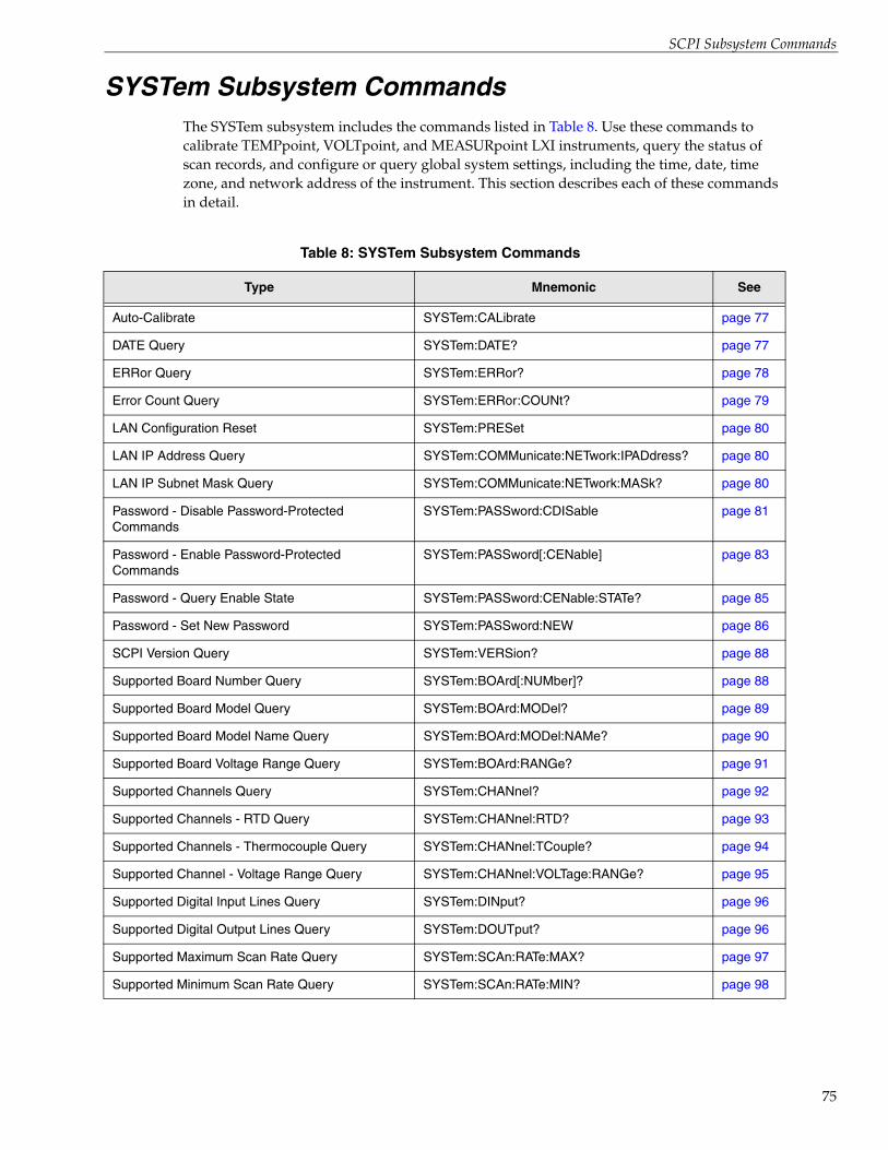
SCPI Subsystem Commands
SYSTem Subsystem CommandsThe SYSTem subsystem includes the commands listed in Table 8. Use these commands to calibrate TEMPpoint, VOLTpoint, and MEASURpoint LXI instruments, query the status of scan records, and configure or query global system settings, including the time, date, time zone, and network address of the instrument. This section describes each of these commands in detail.
Table 8: SYSTem Subsystem Commands
Type Mnemonic See
Auto-Calibrate SYSTem:CALibrate page 77
DATE Query SYSTem:DATE? page 77
ERRor Query SYSTem:ERRor? page 78
Error Count Query SYSTem:ERRor:COUNt? page 79
LAN Configuration Reset SYSTem:PRESet page 80
LAN IP Address Query SYSTem:COMMunicate:NETwork:IPADdress? page 80
LAN IP Subnet Mask Query SYSTem:COMMunicate:NETwork:MASk? page 80
Password - Disable Password-Protected Commands
SYSTem:PASSword:CDISable page 81
Password - Enable Password-Protected Commands
SYSTem:PASSword[:CENable] page 83
Password - Query Enable State SYSTem:PASSword:CENable:STATe? page 85
Password - Set New Password SYSTem:PASSword:NEW page 86
SCPI Version Query SYSTem:VERSion? page 88
Supported Board Number Query SYSTem:BOArd[:NUMber]? page 88
Supported Board Model Query SYSTem:BOArd:MODel? page 89
Supported Board Model Name Query SYSTem:BOArd:MODel:NAMe? page 90
Supported Board Voltage Range Query SYSTem:BOArd:RANGe? page 91
Supported Channels Query SYSTem:CHANnel? page 92
Supported Channels - RTD Query SYSTem:CHANnel:RTD? page 93
Supported Channels - Thermocouple Query SYSTem:CHANnel:TCouple? page 94
Supported Channel - Voltage Range Query SYSTem:CHANnel:VOLTage:RANGe? page 95
Supported Digital Input Lines Query SYSTem:DINput? page 96
Supported Digital Output Lines Query SYSTem:DOUTput? page 96
Supported Maximum Scan Rate Query SYSTem:SCAn:RATe:MAX? page 97
Supported Minimum Scan Rate Query SYSTem:SCAn:RATe:MIN? page 98
75

Chapter 4
76
TIME Query SYSTem:TIME? page 99
Time Zone Query SYSTem:TZONe? page 100
Time Zone Set SYSTem:TZONe page 100
Table 8: SYSTem Subsystem Commands (cont.)
Type Mnemonic See

SCPI Subsystem Commands
Auto-Calibrate
DATE Query
Description Auto-calibrates (auto-zeros) all analog input channels on the instrument.
Syntax :SYSTem:CALibrate
Parameters None
Response Data None
Notes This is a password-protected command. To enable this command to function, use the SYSTem:PASSword[:CENable] command, described on page 83.
Ensure that the instrument is not performing a scan when you execute this command to avoid returning an error.
Example > :SYST:CAL
This command auto-zeros all analog input channels on the instrument.
Description Returns the current date of the instrument. This date is updated automatically by an SNTP (Simple Network Time Protocol) server.
Syntax :SYSTem:DATE?
Parameters None
Response Data <year>,<month>,<day>
Name:
Data Format:
Description:
year
<NR1>
A number representing the year, such as 2008.
Name:
Data Format:
Description:
month
<NR1>
A number from 1 to 12 representing the month.
Name:
Data Format:
Description:
day
<NR1>
A number from 1 to 31 representing the day.
Example > :SYST:DATE?< 2008,1,15
This response indicates that the date of the instrument is January 15th, 2008.
77

Chapter 4
78
ERRor Query
Description This command, which is mandatory for SCPI-compliant devices, reads an error message from the error queue and then removes it from the queue.
Syntax :SYSTem:ERRor[:NEXT]?
Parameters None
Response Data <Error/event_number>,<Error/event_description>, <Device-dependent info>
Data Format <CHARACTER RESPONSE DATA>
Name:
Description:
Error/event_number
A unique integer in the range of –32768 to 32767. A value of 0 indicates that no error or event has occurred. Refer to Appendix A starting on page 163 for a list of errors that can be returned.
Name:
Description:
Error/event_description
A quoted string that contains a description of the error that was read from the Error/Event Queue. Refer to Appendix A starting on page 163 for a list of errors that can be returned.
Name:
Description:
Device-dependent info
Optional text that provides device-dependent information about the error that was read from the Error/Event Queue. Refer to Appendix A starting on page 163 for a list of errors that can be returned.
Notes The maximum string length of <Error/event_description> plus <Device-dependent info> is 255 characters.
The error queue is a first-in, first-out (FIFO) with a capacity of 32 error messages. By querying the error count before and after a SCPI command (in a single command string), you can unambiguously determine whether the command that you issued caused an error. Use the SYSTem:ERRor:COUNt? command, described on page 79, to return the number of unread items in the error queue.
When the queue is full, the message "–350,’Queue overflow’" is returned and subsequent errors can not be added to the queue. Use the *CLS command, described on page 56, to clear the error queue as well as the Status Byte register.
Refer to 1999 SCPI Command Reference, section 21.8, for more information.

SCPI Subsystem Commands
ERRor Count Query
Example The following shows the responses to this query after an invalid command is sent to the instrument:
>:BADc>:SYST:ERR?< -110,"Command header error;:BADc"> :SYST:ERR?< 0,"No error"
Description Queries the error queue for the number of unread items and returns the count.
Syntax :SYSTem:ERRor:COUNt?
Parameters None
Response Data <Count>
Name:
Data Format:
Description:
Count
<0+NR1>
A unique integer that indicates the number of unread errors in the error queue. A value of 0 indicates that the queue is empty.
Since errors may occur at any time, more items may be present in the error queue at the time that it is actually read.
Notes The error queue is a first-in, first-out (FIFO) with a capacity of 32 error messages. The error queue accumulates errors from all clients. By querying the error count before and after a SCPI command (in a single program message), you can unambiguously determine whether the command that you issued caused an error.
When the queue is full, the message "–350,’Queue overflow’" is returned and subsequent errors can not be added to the queue. Use the SYSTem:ERRor command, described on page 78, to read the error and remove if from the queue. Use the *CLS command, described on page 56, to clear the error queue as well as the Status Byte register.
Example The following shows how to query the number of errors in the error queue both before and after the INITialize command.
> :SYST:ERR:COUN?;:INIT;:SYST:ERR:COUN?< 0, 0
79

Chapter 4
80
LAN Configuration Reset
LAN IP Address Query
LAN IP Subnet Mask Query
Description Sets the LAN configuration to default values. The effect of this command is the same as pushing the LAN reset switch on the rear panel of the instrument.
Syntax :SYSTem:PRESet
Parameters None
Response Data None
Notes This command resets the instrument to use the default password. Refer to page 36 for more information on the default password.
Example > :SYST:PRES
Description Returns the static IP address that is currently used by the instrument on the network.
Syntax :SYSTem:COMMunicate:NETwork:IPADdress?
Parameters None
Response Data <ipaddress>
Name:
Data Format:
Description:
ipaddress
String
String of four fields, separated by periods, that contains a maximum of 15 characters, such as "192.43.218.41".
Notes The instrument is configured to use the DHCP server, by default.
Example > :SYST:COMM:NET:IPAD? < 192.43.218.85
This string represents the IP address of the instrument.
Description Returns the static IP subnet mask that is currently used by the instrument on the network.
Syntax :SYSTem:COMMunicate:NETwork:MASk?
Parameters None
Response Data <mask>
Name:
Data Format:
Description:
mask
String
String of four fields, separated by periods, that contains a maximum of 15 characters, such as "255.255.255.0".

SCPI Subsystem Commands
Password - Disable Password-Protected Commands
Notes TEMPpoint, VOLTpoint, and MEASURpoint LXI instruments are configured to use the DHCP server, by default.
Example > :SYST:COMM:NET:MAS? < 255.255.255.0
This string represents the IP subnet mask of the instrument.
Description Disables use of the following commands and queries, which are password protected:
• OUTPut[:STATe], described on page 151
• CONFigure:VOLTage, described on page 109
• CONFigure:RESistance, described on page 103
• CONFigure:TEMPerature:TCouple, described on page 106
• CONFigure:TEMPerature:RTD, described on page 104
• CONFigure:VOLTage:RANGe, described on page 111
• CONFigure:SCAn:LISt, described on page 120
• CONFigure:SCAn:CJC, described on page 118
• CONFigure:SCAn:RATe[:SEC|HZ], described on page 123
• CONFigure:FILTer, described on page 115
• CONFigure:TRIGger[:SOURce], described on page 127
• INITiate, described on page 140
• ABORt, described on page 143
• MEASure:VOLTage?, described on page 137
• MEASure:RESistance?, described on page 130
• MEASure:TEMPerature:TCouple?, described on page 134
• MEASure:TEMPeratuer:RTD?, described on page 131
• SYSTem:TZONe, described on page 100
• SYSTem:CALibrate, described on page 77
Syntax :SYSTem:PASSword:CDISable <password>
Parameters
Name:
Data Format:
Description:
password
<CHARACTER PROGRAM DATA>
Specifies the password that is stored in permanent memory on the instrument. This string is case-sensitive.
Response Data None
81
Chapter 4
82
Notes On power up, all SCPI password-protected commands and queries are disabled. If the instrument is powered down, you must enable the password-protected commands when the instrument is powered back up if you want to configure or operate the instrument.
Once the password-protected commands are disabled, issuing any of the password-protected commands will result in error –203, Command protected.
By default, the password is admin. You can change the password using the SYSTem:PASSword:NEW command, described on page 86.
Note: The DT8871, DT8871U, DT8872, DT8873, and DT8874 instruments with firmware version 2.2.3.1 or greater use the default user name "admin" and the default password "admin". Firmware version 2.2.3.1 and greater support password-protected commands. Therefore, you must enter the appropriate password to change the instrument’s configuration or to start and stop a scan.
Firmware versions less than 2.2.3.1 do not support password-protected commands. Therefore, you are not prompted to enter a password to change the instrument’s configuration or to start or stop a scan.
You can re-enable password-protected commands using the SYSTem:PASSword[:CENable] command, described on page 83.
Example The following example shows an attempt to disable protected commands using an erroneous password:
> :SYSTem:PASSword:CDISable bogus> :SYST:ERR?< -221,"Settings conflict;:SYST:PASS:CDIS"
The following is an example in which the correct password is used to disable protected commands:
> :SYSTem:PASSword:CDISable admin> :SYST:ERR?< 0,"No error"> :SYSTem:PASSword:CENable:STATe?< 0
Since protected commands are disabled, any attempt to use them will fail, as shown in the following example:
> :CONF?< PT1000,PT1000,PT1000,PT1000> :CONF:TEMP:RTD PT1000> :SYST:ERR?< -203,"Command protected"
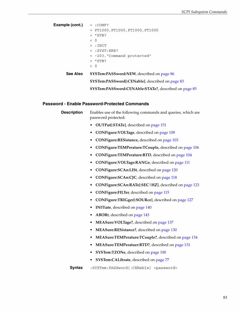
SCPI Subsystem Commands
Password - Enable Password-Protected Commands
Example (cont.) > :CONF?< PT1000,PT1000,PT1000,PT1000> *STB?< 0> :INIT> :SYST:ERR?< -203,"Command protected"> *STB?< 0
See Also SYSTem:PASSword:NEW, described on page 86
SYSTem:PASSword[:CENable], described on page 83
SYSTem:PASSword:CENAble:STATe?, described on page 85
Description Enables use of the following commands and queries, which are password protected:
• OUTPut[:STATe], described on page 151
• CONFigure:VOLTage, described on page 109
• CONFigure:RESistance, described on page 103
• CONFigure:TEMPerature:TCouple, described on page 106
• CONFigure:TEMPerature:RTD, described on page 104
• CONFigure:VOLTage:RANGe, described on page 111
• CONFigure:SCAn:LISt, described on page 120
• CONFigure:SCAn:CJC, described on page 118
• CONFigure:SCAn:RATe[:SEC|HZ], described on page 123
• CONFigure:FILTer, described on page 115
• CONFigure:TRIGger[:SOURce], described on page 127
• INITiate, described on page 140
• ABORt, described on page 143
• MEASure:VOLTage?, described on page 137
• MEASure:RESistance?, described on page 130
• MEASure:TEMPerature:TCouple?, described on page 134
• MEASure:TEMPeratuer:RTD?, described on page 131
• SYSTem:TZONe, described on page 100
• SYSTem:CALibrate, described on page 77
Syntax :SYSTem:PASSword[:CENable] <password>
83

Chapter 4
84
Parameters
Name:
Data Format:
Description:
password
<CHARACTER PROGRAM DATA>
Specifies the password that is stored in permanent memory in the instrument. This string is case-sensitive.
Response Data None
Notes On power up, the SCPI password-protected commands and queries are disabled. If the instrument is powered down, you must enable the password-protected commands when the instrument is powered back up if you want to configure or operate the instrument.
Once the password-protected commands are disabled, issuing any of the password-protected commands will result in error –203, Command protected.
By default, the password is admin. You can change the password using the SYSTem:PASSword:NEW command, described on page 86.
Note: The DT8871, DT8871U, DT8872, DT8873, and DT8874 instruments with firmware version 2.2.3.1 or greater use the default user name "admin" and the default password "admin". Firmware version 2.2.3.1 and greater support password-protected commands. Therefore, you must enter the appropriate password to change the instrument’s configuration or to start and stop a scan.
Firmware versions less than 2.2.3.1 do not support password-protected commands. Therefore, you are not prompted to enter a password to change the instrument’s configuration or to start or stop a scan.
Example In the following example, the command to enable password-protected commands is successful; therefore, the client can configure the instrument and operate it.:
> :SYST:PASS:CEN admin> :SYSTem:PASSword:CENable:STATe?< 1> :CONF?< PT1000,PT1000,PT1000,PT1000> :CONF:TEMP:RTD PT100> :CONF?< PT100,PT100,PT100,PT100
See Also SYSTem:PASSword:NEW, described on page 86
SYSTem:PASSword:CDISable, described on page 81
SYSTem:PASSword:CENAble:STATe?, described on page 85
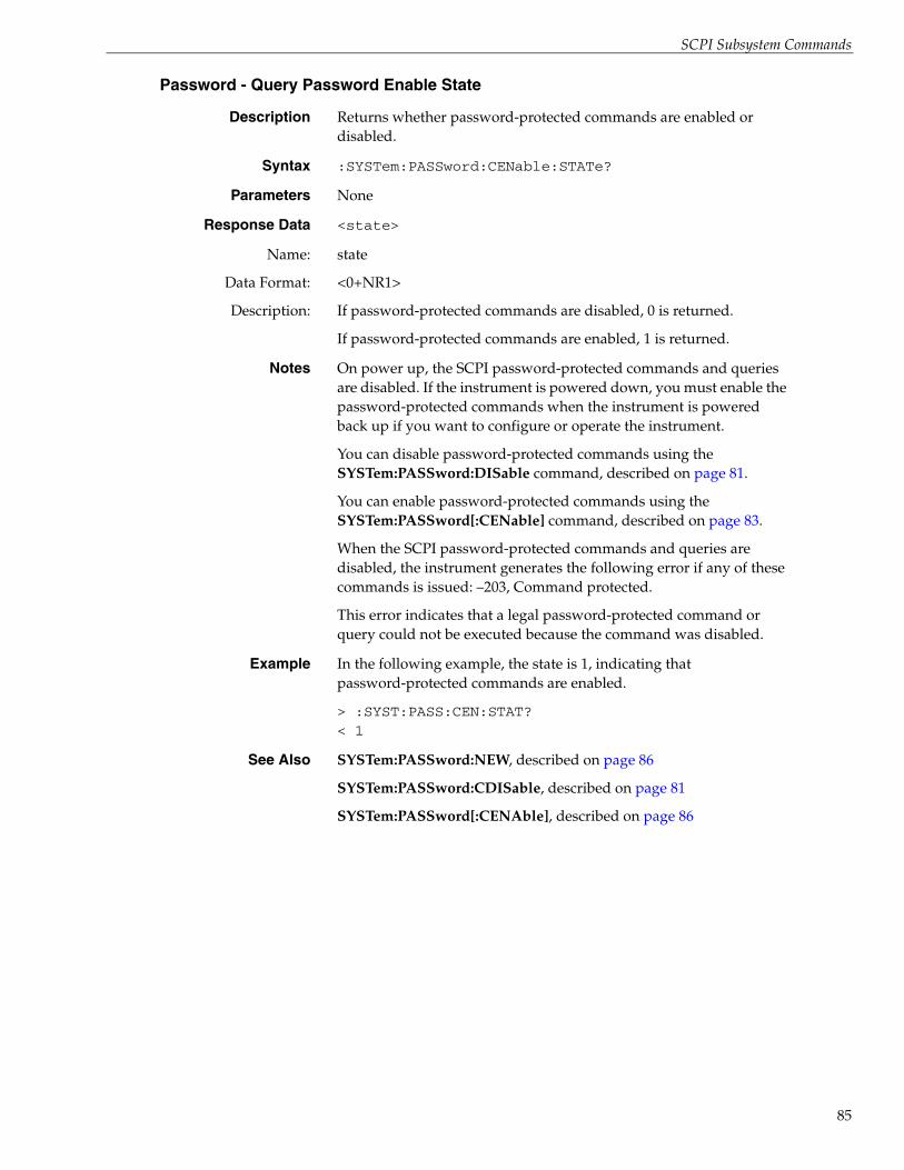
SCPI Subsystem Commands
Password - Query Password Enable State
Description Returns whether password-protected commands are enabled or disabled.
Syntax :SYSTem:PASSword:CENable:STATe?
Parameters None
Response Data <state>
Name:
Data Format:
Description:
state
<0+NR1>
If password-protected commands are disabled, 0 is returned.
If password-protected commands are enabled, 1 is returned.
Notes On power up, the SCPI password-protected commands and queries are disabled. If the instrument is powered down, you must enable the password-protected commands when the instrument is powered back up if you want to configure or operate the instrument.
You can disable password-protected commands using the SYSTem:PASSword:DISable command, described on page 81.
You can enable password-protected commands using the SYSTem:PASSword[:CENable] command, described on page 83.
When the SCPI password-protected commands and queries are disabled, the instrument generates the following error if any of these commands is issued: –203, Command protected.
This error indicates that a legal password-protected command or query could not be executed because the command was disabled.
Example In the following example, the state is 1, indicating that password-protected commands are enabled.
> :SYST:PASS:CEN:STAT?< 1
See Also SYSTem:PASSword:NEW, described on page 86
SYSTem:PASSword:CDISable, described on page 81
SYSTem:PASSword[:CENAble], described on page 86
85
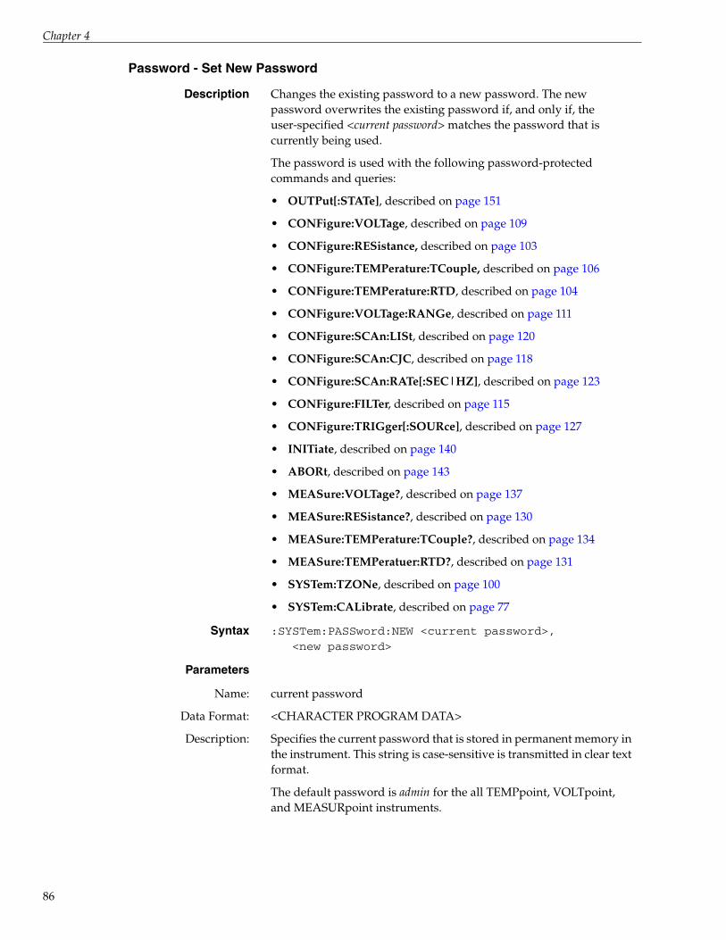
Chapter 4
86
Password - Set New Password
Description Changes the existing password to a new password. The new password overwrites the existing password if, and only if, the user-specified <current password> matches the password that is currently being used.
The password is used with the following password-protected commands and queries:
• OUTPut[:STATe], described on page 151
• CONFigure:VOLTage, described on page 109
• CONFigure:RESistance, described on page 103
• CONFigure:TEMPerature:TCouple, described on page 106
• CONFigure:TEMPerature:RTD, described on page 104
• CONFigure:VOLTage:RANGe, described on page 111
• CONFigure:SCAn:LISt, described on page 120
• CONFigure:SCAn:CJC, described on page 118
• CONFigure:SCAn:RATe[:SEC|HZ], described on page 123
• CONFigure:FILTer, described on page 115
• CONFigure:TRIGger[:SOURce], described on page 127
• INITiate, described on page 140
• ABORt, described on page 143
• MEASure:VOLTage?, described on page 137
• MEASure:RESistance?, described on page 130
• MEASure:TEMPerature:TCouple?, described on page 134
• MEASure:TEMPeratuer:RTD?, described on page 131
• SYSTem:TZONe, described on page 100
• SYSTem:CALibrate, described on page 77
Syntax :SYSTem:PASSword:NEW <current password>,<new password>
Parameters
Name:
Data Format:
Description:
current password
<CHARACTER PROGRAM DATA>
Specifies the current password that is stored in permanent memory in the instrument. This string is case-sensitive is transmitted in clear text format.
The default password is admin for the all TEMPpoint, VOLTpoint, and MEASURpoint instruments.

SCPI Subsystem Commands
Description (cont.):
Note: The DT8871, DT8871U, DT8872, DT8873, and DT8874 instruments with firmware version 2.2.3.1 or greater use the default user name "admin" and the default password "admin". Firmware version 2.2.3.1 and greater support password-protected commands. Therefore, you must enter the appropriate password to change the instrument’s configuration or to start and stop a scan.
Firmware versions less than 2.2.3.1 do not support password-protected commands. Therefore, you are not prompted to enter a password to change the instrument’s configuration or to start or stop a scan.
Name:
Data Format:
Description:
new password
<CHARACTER PROGRAM DATA>
Specifies the new password that will overwrite the current password and be saved in permanent memory in the instrument. This string is case-sensitive and is transmitted in clear text format.
Response Data None
Notes The new password becomes effective immediately. The instrument does not need to be rebooted. The new password is reflected in the LAN configuration web page for the instrument (see the user’s manual for your instrument for more information on this web page).
The new password is enforced when any attempt is made to configure the instrument using SCPI commands, the instrument’s web pages, or the IVI-COM driver.
Since the <current password> and <new password> are strings that are transmitted in clear text format, they can be determined easily by snooping LAN traffic.
Example The following example shows an attempt to change the password using a wrong password:
> :SYST:PASS:NEW bogus, admin1> :SYST:ERR?< -221,"Settings conflict;:SYST:PASS:NEW"
In the following example, the existing password admin is successfully changed to admin1:
> :SYST:PASS:NEW admin, admin1> :SYST:ERR?< 0,"No error"
See Also SYSTem:PASSword[:CENable], described on page 83
SYSTem:PASSword:CDISable, described on page 81
SYSTem:PASSword:CENAble:STATe?, described on page 85
87

Chapter 4
88
SCPI Version Query
Supported Board Number Query
Description This command, which is mandatory for SCPI-compliant devices, returns the SCPI version number to which the instrument complies.
Syntax :SYSTem:VERSion?
Parameters None
Response Data <YYYY>.<V>
Name:
Data Format:
Description:
YYYY
<NR2>
The year of the version, such as 2008.
Name:
Data Format:
Description:
V
<NR2>
The approved SCPI revision number for that year, such as 0.
Notes Refer to 1999 SCPI Command Reference, section 21.21 for more information.
Example > :SYST:VERS?< 1999.0
In this example, the version is year 1999 and the SCPI revision is 0.
Description Returns the number of boards installed in the instrument.
Syntax :SYSTem:BOArd[:NUMber]?
Parameters None
Response Data <board number>
Name:
Data Format:
Description:
board number
<0+NR1>
The number of boards that are installed in the instrument. This value can range from 0 to 6.
Example The following example returns the number of boards installed in a MEASURpoint instrument; in this case, 6 boards are installed:
> :SYST:BOA?< 6
See Also SYSTem:BOArd:MODel?, described on page 89
SYSTem:BOArd:MODel:NAMe?, described on page 90

SCPI Subsystem Commands
Supported Board Model Query
Description Returns the model of a specific board installed in the instrument.
Syntax :SYSTem:BOArd:MODel? <board number>
Parameters
Name:
Data Format:
Description:
board number
<0+NR1>
Specifies the board number to query. This value can range from 1 to 8.
Response Data <model>
Name:
Data Format:
Description:
model
<0+NR1>
The model of the specified board in the instrument. The following values are supported:
• 0 – DT8771 (This is a thermocouple board.)
• 1 – DT8871U (This is a thermocouple board.)
• 2 – DT8873-100V (This is a voltage board with a fixed range of±100 V. This is an older board model that has been replaced
by the DT8873-MULTI board type.)
• 3 – DT8873-10V (This is a voltage board with a fixed range of±10 V. This is an older board model that has been replaced
by the DT8873-MULTI board type.)
• 4 – DT8873-400V (This is a voltage board with a fixed range of ±400 V. This is an older board model that has been replaced
by the DT8873-MULTI board type.)
• 5 – DT8872 (This is an RTD board.)
• 7 – DT8873-MULTI (This is a voltage board that supportsprogrammable voltage ranges of ±10 V and ±60 V.)
Notes DT8871, DT8871U, DT8872, and DT8873 instruments with firmware version 2.2.3.1 or greater are identified in firmware as DT8874-xxT-xxR-xx-V, where xxT specifies the number of thermocouple channels, xxR specifies the number of RTD channels, and xxV specifies the number of voltage input channels.
Instruments may contain multiple board names/models. For example, a DT8874-24T-08R-16V, contains thermocouple boards, RTD boards, and voltage input boards. By querying the board name/model, you can determine which boards comprise your instrument.
89

Chapter 4
90
Supported Board Model Name Query
Example The following example returns the model of board number 3 in a MEASURpoint instrument; in this case, the model is 5, representing the DT8872 RTD board:
> :SYST:BOA:MOD? 3< 5
See Also SYSTem:BOArd:MODel?, described on page 89
SYSTem:BOArd:MODel:NAMe?, described on page 90
SYSTem:BOArd:RANGe?, described on page 91
Description Returns the name of the board that is installed in the instrument.
Syntax :SYSTem:BOArd:MODel:NAMe? <board number>
Parameters
Name:
Data Format:
Description:
board number
<0+NR1>
Specifies the board number to query. This value can range from 1 to 8.
Response Data <name>
Name:
Data Format:
Description:
name
<CHARACTER RESPONSE DATA>
The name of the specified board in the instrument. The following names are supported:
• DT8771 (This is a thermocouple board.)
• DT8871U (This is a thermocouple board.)
• DT8873-100V (This is a voltage board with a fixed range of ±100 V. This is an older board model that has been replaced by the DT8873-MULTI board type)
• DT8873-10V (This is a voltage board with a fixed range of ±10 V. This is an older board model that has been replaced by the DT8873-MULTI board type)
• DT8873-400V (This is a voltage board with a fixed range of ±400 V.) This is an older board model that has been replaced by the DT8873-MULTI board type
• DT8872 (This is an RTD board.)
• DT8873-MULTI (This is a voltage board that supports programmable voltage ranges of ±10 V and ±60 V.)
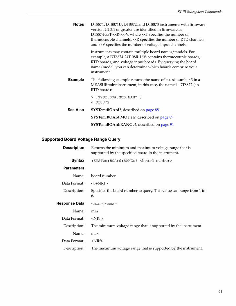
SCPI Subsystem Commands
Supported Board Voltage Range Query
Notes DT8871, DT8871U, DT8872, and DT8873 instruments with firmware version 2.2.3.1 or greater are identified in firmware as DT8874-xxT-xxR-xx-V, where xxT specifies the number of thermocouple channels, xxR specifies the number of RTD channels, and xxV specifies the number of voltage input channels.
Instruments may contain multiple board names/models. For example, a DT8874-24T-08R-16V, contains thermocouple boards, RTD boards, and voltage input boards. By querying the board name/model, you can determine which boards comprise your instrument.
Example The following example returns the name of board number 3 in a MEASURpoint instrument; in this case, the name is DT8872 (an RTD board):
> :SYST:BOA:MOD:NAM? 3< DT8872
See Also SYSTem:BOArd?, described on page 88
SYSTem:BOArd:MODel?, described on page 89
SYSTem:BOArd:RANGe?, described on page 91
Description Returns the minimum and maximum voltage range that is supported by the specified board in the instrument.
Syntax :SYSTem:BOArd:RANGe? <board number>
Parameters
Name:
Data Format:
Description:
board number
<0+NR1>
Specifies the board number to query. This value can range from 1 to 6.
Response Data <min>,<max>
Name:
Data Format:
Description:
min
<NRf>
The minimum voltage range that is supported by the instrument.
Name:
Data Format:
Description:
max
<NRf>
The maximum voltage range that is supported by the instrument.
91

Chapter 4
92
Supported Channels Query
Example The following example returns the minimum and maximum voltage range that is supported by a DT8873-MULTI board (board 0, in this case) in a MEASURpoint instrument:
> :SYST:BOA:RANG? 0< -60.000,60.000
This example returns the minimum and maximum voltage range that is supported by a DT8872 board (board 1, in this case) in a MEASURpoint instrument:
> :SYST:BOA:RANG? 1< -1.250,1.250
See Also SYSTem:BOArd?, described on page 88
SYSTem:BOArd:MODel?, described on page 89
SYSTem:BOArd:MODel:NAMe?, described on page 90
Description Returns a list of all the analog input channels that are supported on the instrument.
Syntax :SYSTem:CHANnel?
Parameters None
Response Data <channel_list>
Name:
Data Format:
Description:
channel_list
<0+NR1><CHARACTER PROGRAM DATA>
The list of all the analog input channels that are supported on the instrument.
If no analog input channels are supported on the instrument, an empty list (@) is returned.
Notes Depending on the model of the instrument, you can configure the channel to measure temperature, voltage, or resistance using the following commands:
• CONFigure:TEMPerature:TCouple, described on page 106
• CONFigure:TEMPerature:RTD, described on page 104
• CONFigure:RESistance, described on page 103
• CONFigure:VOLTage, described on page 109
• CONFigure:VOLTage:RANGe, described on page 111

SCPI Subsystem Commands
Supported RTD Channels Query
Example The following example returns the list of supported analog input channels on an instrument; in this case, 24 channels (0 to 23) are supported:
> :SYST:CHAN?< @0:23
See Also CONFigure:VOLTage, described on page 109
CONFigure:VOLTage:RANGe, described on page 111
CONFigure:TEMPerature:TCouple, described on page 106
CONFigure:TEMPerature:RTD, described on page 104
CONFigure:RESistance, described on page 103
SYSTem:DINput?, described on page 96
SYSTem:DOUTput?, described on page 96
Description Returns a list of analog input channels that support RTDs on the instrument.
Syntax :SYSTem:CHANnel:RTD?
Parameters None
Response Data <channel_list>
Name:
Data Format:
Description:
channel_list
<0+NR1><CHARACTER PROGRAM DATA>
The list of analog input channels that support RTDs on the instrument.
If no channels support RTDs on the instrument, an empty list (@) is returned.
Notes If a channel supports an RTD, you can configure the channel to measure temperature, voltage, or resistance using the following commands:
• CONFigure:TEMPerature:RTD, described on page 104
• CONFigure:RESistance, described on page 103
• CONFigure:VOLTage, described on page 109
Example The following example returns the list of analog input channels that are supported on the instrument as well as the channels that support RTDs; in this case, all 48 channels (0 to 47) support RTDs:
> :SYST:CHAN?< @0:47> :SYST:CHAN:RTD?< @0:47
93

Chapter 4
94
Supported Thermocouple Channels Query
Example (cont.) In the following example, only channels 8 to 15 of the available 48 channels support RTDs:
> :SYST:CHAN?< @0:47> :SYST:CHAN:RTD?< @8:15
See Also CONFigure:TEMPerature:RTD, described on page 104
CONFigure:RESistance, described on page 103
CONFigure:VOLTage, described on page 109
SYSTem:CHANnel?, described on page 92
SYSTem:CHANnel:TCouple?, described on page 94
SYSTem:CHANnel:VOLTage:RANGe?, described on page 95
Description Returns a list of analog input channels that support thermocouples on the instrument.
Syntax :SYSTem:CHANnel:TCouple?
Parameters None
Response Data <channel_list>
Name:
Data Format:
Description:
channel_list
<0+NR1><CHARACTER PROGRAM DATA>
The list of analog input channels that support thermocouples on the instrument.
If no channels support thermocouples on the instrument, an empty list (@) is returned.
If a channel supports a thermocouple, you can configure the channel to measure temperature or voltage using the following commands:
• CONFigure:TEMPerature:TCouple, described on page 106
• CONFigure:VOLTage, described on page 109
Example The following example returns the list of analog input channels that are supported on the instrument as well as those that support thermocouples; in this case, all 48 channels (0 to 47) support thermocouples:
> :SYST:CHAN?< @0:47> :SYST:CHAN:TC?< @0:47

SCPI Subsystem Commands
Supported Voltage Range Query
Example (cont.) In the following example, only channels 0 to 15 of the available 48 channels support thermocouples:
> :SYST:CHAN?< @0:47> :SYST:CHAN:TC?< @0:15
See Also CONFigure:TEMPerature:TCouple, described on page 106
CONFigure:VOLTage, described on page 109
SYSTem:CHANnel?, described on page 92
SYSTem:CHANnel:RTD?, described on page 93
SYSTem:CHANnel:VOLTage:RANGe?, described on page 95
Description Returns a list of channels that support programmable voltage ranges on the specified instrument.
Syntax :SYSTem:CHANnel:VOLTage:RANGe?
Parameters None
Response Data <channel_list>
Name:
Data Format:
Description:
channel_list
<0+NR1><CHARACTER PROGRAM DATA>
The list of analog input channels that support programmable voltage ranges on the instrument.
If no channels support programmable voltage ranges on the instrument, an empty list (@) is returned.
Notes If a channel supports programmable voltage ranges, you can configure the channel for the range using the CONFigure:VOLTage:RANGe command, described on page 111.
Example The following example returns which channels support programmable voltage ranges; in this case, channels 0 to 7 support thermocouples, while channels 8 to 15 support RTDs, and channels 16 through 23 support programmable voltage ranges:
> *IDN?< Data Translation,DT8874-08T,08R,08V,-1,1.8,0.0>:SYSTem:CHANnel?< (@0:23)>:SYSTem:CHANnel:RTD?< (@8:15)>:SYSTem:CHANnel:TC?< (@0:7)>:SYST:CHAN:VOLT:RANG?< (@16:23)
95
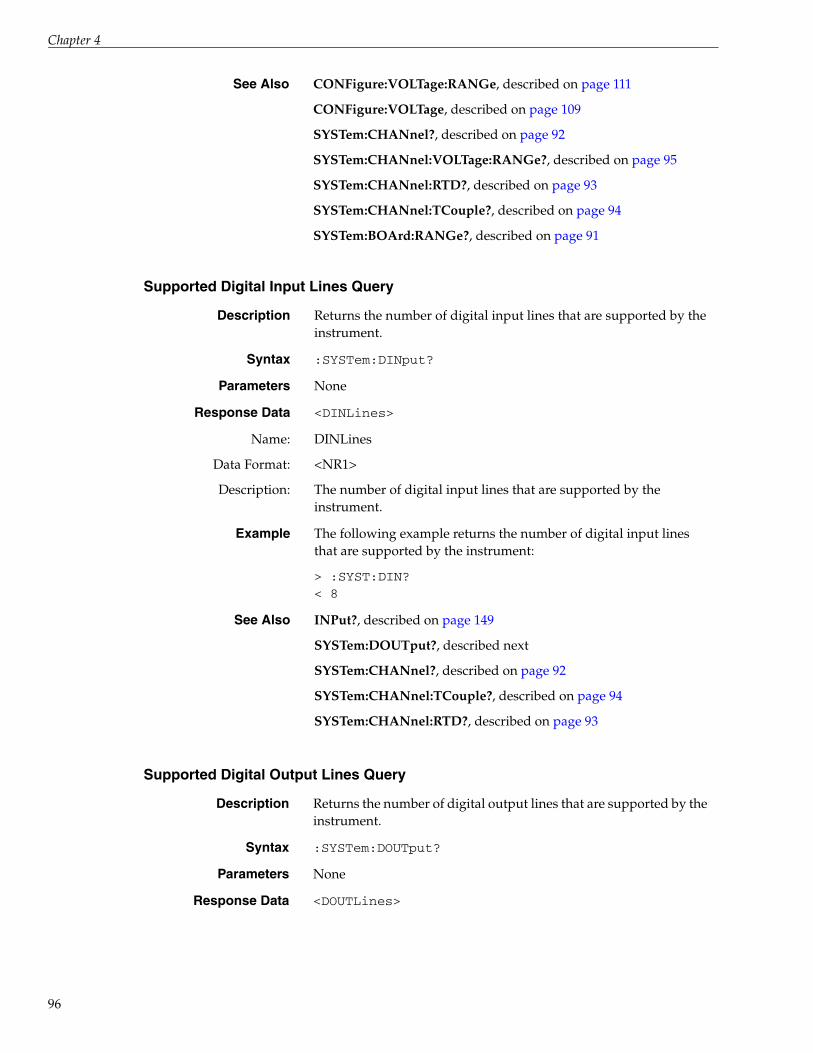
Chapter 4
96
Supported Digital Input Lines Query
Supported Digital Output Lines Query
See Also CONFigure:VOLTage:RANGe, described on page 111
CONFigure:VOLTage, described on page 109
SYSTem:CHANnel?, described on page 92
SYSTem:CHANnel:VOLTage:RANGe?, described on page 95
SYSTem:CHANnel:RTD?, described on page 93
SYSTem:CHANnel:TCouple?, described on page 94
SYSTem:BOArd:RANGe?, described on page 91
Description Returns the number of digital input lines that are supported by the instrument.
Syntax :SYSTem:DINput?
Parameters None
Response Data <DINLines>
Name:
Data Format:
Description:
DINLines
<NR1>
The number of digital input lines that are supported by the instrument.
Example The following example returns the number of digital input lines that are supported by the instrument:
> :SYST:DIN?< 8
See Also INPut?, described on page 149
SYSTem:DOUTput?, described next
SYSTem:CHANnel?, described on page 92
SYSTem:CHANnel:TCouple?, described on page 94
SYSTem:CHANnel:RTD?, described on page 93
Description Returns the number of digital output lines that are supported by the instrument.
Syntax :SYSTem:DOUTput?
Parameters None
Response Data <DOUTLines>

SCPI Subsystem Commands
Supported Maximum Scan Rate Query
Name:
Data Format:
Description:
DOUTLines
<NR1>
The number of digital output lines that are supported by the instrument.
Example The following example returns the number of digital output lines that are supported by the instrument:
> :SYST:DOUT?< 8
See Also OUTPut, described on page 151
SYSTem:DINput?, described on page 96
SYSTem:CHANnel?, described on page 92
SYSTem:CHANnel:TCouple?, described on page 94
SYSTem:CHANnel:RTD?, described on page 93
Description Returns the maximum scan rate or scan frequency that is supported by the instrument.
Syntax :SYSTem:SCAn:RATe:MAXimum[:SEC|HZ]?
Optional Keywords
Name:
Data Format:
Description:
SEC|HZ
<CHARACTER PROGRAM DATA>
Optional enumerated type that specifies whether to return the maximum scan rate in seconds (SEC) or the maximum scan frequency, in Hertz (HZ).
If this keyword is omitted, SEC is used by default.
Parameters None
Response Data <MaxRate>
Name:
Data Format:
Description:
MaxRate
<NRf>
If SEC is specified or if neither SEC nor HZ is specified for the SEC|HZ keyword, returns a floating-point value that represents the maximum time period of each scan, in seconds.
If HZ is specified for the SEC|HZ keyword, returns a floating-point value that represents the maximum scan frequency, in Hertz.
Currently, all TEMPpoint, VOLTpoint, and MEASURpoint LXI instruments support a maximum scan rate of 0.1 s and a maximum scan frequency of 10 Hz.
97

Chapter 4
98
Supported Minimum Scan Rate Query
Notes You can configure the scan rate or scan frequency of the instrument using the CONFigure:SCAn:RATe command, described on page 123.
Example The following example returns the maximum scan rate that is supported by the instrument, in seconds:
> :SYST:SCA:RAT:MIN:SEC?< 0.100000
This example returns the minimum scan frequency that is supported by the instrument, in Hertz:
> :SYST:SCA:RAT:MIN:HZ?< 10.000000
See Also SYSTem:SCAn:RATe:MIN?, described on page 98
CONFigure:SCAn:RATe command, described on page 123
Description Returns the minimum scan rate or scan frequency that is supported by the instrument.
Syntax :SYSTem:SCAn:RATe:MINimum[:SEC|HZ]?
Optional Keywords
Name:
Data Format:
Description:
SEC|HZ
<CHARACTER PROGRAM DATA>
Optional enumerated type that specifies whether to return the minimum scan rate in seconds (SEC) or the minimum scan frequency, in Hertz (HZ).
If this keyword is omitted, SEC is used by default.
Parameters None
Response Data <MinRate>
Name:
Data Format:
Description:
MinRate
<NRf>
If SEC is specified or if neither SEC nor HZ is specified for the SEC|HZ keyword, returns a floating-point value that represents the minimum time period of each scan, in seconds.
If HZ is specified for the SEC|HZ keyword, returns a floating-point value that represents the minimum scan frequency, in Hertz.
Currently, all TEMPpoint, VOLTpoint, and MEASURpoint LXI instruments support a minimum scan rate of 6553.5 s and a minimum scan frequency of 1.525e-4 Hz (10 Hz/65535).
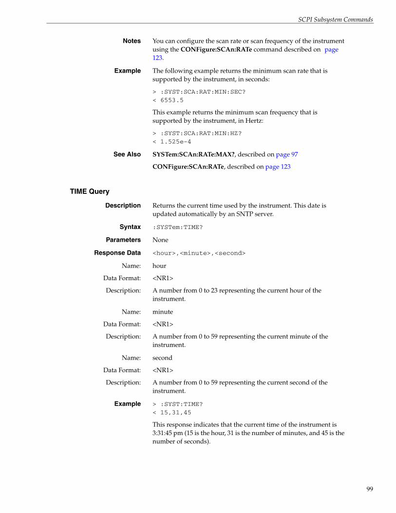
SCPI Subsystem Commands
TIME Query
Notes You can configure the scan rate or scan frequency of the instrument using the CONFigure:SCAn:RATe command described on page 123.
Example The following example returns the minimum scan rate that is supported by the instrument, in seconds:
> :SYST:SCA:RAT:MIN:SEC?< 6553.5
This example returns the minimum scan frequency that is supported by the instrument, in Hertz:
> :SYST:SCA:RAT:MIN:HZ?< 1.525e-4
See Also SYSTem:SCAn:RATe:MAX?, described on page 97
CONFigure:SCAn:RATe, described on page 123
Description Returns the current time used by the instrument. This date is updated automatically by an SNTP server.
Syntax :SYSTem:TIME?
Parameters None
Response Data <hour>,<minute>,<second>
Name:
Data Format:
Description:
hour
<NR1>
A number from 0 to 23 representing the current hour of the instrument.
Name:
Data Format:
Description:
minute
<NR1>
A number from 0 to 59 representing the current minute of the instrument.
Name:
Data Format:
Description:
second
<NR1>
A number from 0 to 59 representing the current second of the instrument.
Example > :SYST:TIME?< 15,31,45
This response indicates that the current time of the instrument is 3:31:45 pm (15 is the hour, 31 is the number of minutes, and 45 is the number of seconds).
99

Chapter 4
100
Time Zone Query
Time Zone Set
Description Returns the time zone that is currently used by the instrument, as an offset from GMT (Greenwich Mean Time).
Syntax :SYSTem:TZONe?
Required Parameters None
Response Data
Name:
Data Format:
Description:
hour
<NR1>
A number from –12 to +12 representing the current hour relative to GMT.
Name:
Data Format:
Description:
minute
<NR1>
A number from –59 to +59 representing the current minute relative to GMT. Minutes are rounded up to 30.
Response Data None
Example > :SYST:TZON< +5,-45
This response indicates that the current time zone of the instrument is four hours and 30 minutes ahead of GMT. Minutes are rounded up to 30.
Description Sets the time zone currently used by the instrument, as an offset from GMT (Greenwich Mean Time). The specified hour and minute is added to the UTC (Coordinated Universal Time) time that is maintained by the instrument.
Syntax :SYSTem:TZONe <hour>[,minute]
Required Parameters
Name:
Data Format:
Description:
hour
<NR1>
A number from –12 to +12 representing the current hour relative to GMT. The default value is 0.

SCPI Subsystem Commands
Optional Parameters
Name:
Data Format:
Description:
minute
<NR1>
A number from –59 to +59 representing the current minute relative to GMT. The default value is 0.
Minutes are rounded up to 30.
Response Data None
Notes This is a password-protected command. To enable this command to function, use the SYSTem:PASSword[:CENable] command, described on page 83.
Example > :SYST:TZON +5,-45
This commands sets the current time zone used by the instrument to four hours and 30 minutes ahead of GMT. Minutes are rounded up to 30.
101

Chapter 4
102
CONFigure Subsystem CommandsThe CONFigure subsystem is used to configure and query settings of a TEMPpoint, VOLTpoint, or MEASURpoint LXI instrument. Table 9 lists the commands in the CONFigure subsystem. This section describes each of these commands in detail.
Table 9: CONFigure Subsystem Commands
Type Mnemonic See
Channel Configuration for Resistance CONFigure: RESistance page 103
Channel Configuration for RTD Temperature Measurements
CONFigure:TEMPerature:RTD page 103
Channel Configuration for Thermocouple Temperature Measurements
CONFigure:TEMPerature:TCouple page 106
Channel Configuration for Voltage CONFigure:VOLTage page 109
Channel Configuration for Programmable Voltage Ranges
CONFigure:VOLTage:RANGe page 111
Channel Configuration Query CONFigure? page 113
Filter Configuration CONFigure:FILTer page 115
Filter Query CONFigure:FILTer? page 116
Scan Circular Buffer Query CONFigure:SCAn:BUFfer? page 117
Scan CJC Configuration CONFigure:SCAn:CJC page 118
Scan CJC Query CONFigure:SCAn:CJC? page 119
Scan List Configuration CONFigure:SCAn:LISt page 120
Scan List Query CONFigure:SCAn:LISt? page 122
Scan Rate Configuration CONFigure:SCAn:RATe page 123
Scan Rate Query CONFigure:SCAn:RATe? page 125
Trigger Source Configuration CONFigure:TRIgger[:SOURce] page 127
Trigger Source Query CONFigure:TRIgger[:SOURce]? page 128

SCPI Subsystem Commands
Channel Configuration for Resistance
Description For channels that support RTDs, configures specified channels for resistance measurements. This command affects the configuration of the specified channels only.
Syntax :CONFigure:RESistance [channel_list]
Required Parameters None
Optional Parameters
Name:
Data Format:
Description:
channel_list
<0+NR1><CHARACTER PROGRAM DATA>
Specifies the channels to configure for resistance measurements.
The number of channels that you can specify depends on the configuration of your instrument.
To determine the list of all analog input channels that are supported on your instrument, use the SYSTem:CHANnel? command, described on page 92.
Use the SYSTem:CHANnel:RTD? command, described on page 93, to determine which channels support RTDs; if a channel supports RTDs, you can configure it for temperature, voltage, or resistance measurements.
If this parameter is omitted, all analog input channels are configured for resistance measurements, by default.
Response Data None
Notes This is a password-protected command. To enable this command to function, use the SYSTem:PASSword[:CENable] command, described on page 83.
A Command Error is generated if the specified channel list includes a channel number less than 0 or greater than the maximum number of supported channels. If bit 5 (CME) of the Standard Event Status Enable register is enabled, a Command Error sets bit 5 (CME) of the Standard Event Status register.
An Execution Error is generated if the instrument is scanning, that is an INITiate command was issued and was not aborted, prior to issuing this command. If bit 4 (E) of the Standard Event Status Enable register is enabled, an Execution Error sets bit 4 (E) of the Standard Event Status register.
The summary of the Standard Event Status register is available in bit 5 (ESB) of the Status Byte register.
When an error is encountered, an error string is appended to the error queue, and bit 2 (EAV) of the Status Byte register is set.
Refer to 1999 SCPI Command Reference, section 3.1 and 3.7.2, and 1999 SCPI Syntax & Style, section 8.3.2 for more information.
103

Chapter 4
104
Channel Configuration for RTD Temperatures
Example The following command configures analog input channels 0, 3 through 7, and 47 on the instrument for resistance measurements:
> :CONF:RES (@0,3:7,47)
This command configures all analog input channels on the instrument for resistance measurements:
> :CONF:RES
This command configures analog input channels 1, 2, and 8 through 46 on the instrument for resistance measurements:
> :CONF:RES (@1,2,8:46)
See Also SYSTem:CHANnel?, described on page 92
SYSTem:CHANnel:RTD?, described on page 93
CONFigure?, described on page 113
CONFigure:TEMPerature:RTD, described on page 104
CONFigure:VOLTage, described on page 109
Description Configures specified channels on the instrument for RTD temperature measurements. This command affects the configuration of the specified channels only.
Syntax :CONFigure:TEMPerature:RTD {PT100|PT500|PT1000| A_PT100|A_PT500|A_PT1000|PT100_3|PT500_3|PT1000_3|A_PT100_3|A_PT500_3|A_PT1000_3|DEFault} [,channel_list]
Required Parameters
Name:
Data Format:
Description:
{PT100|PT500|PT1000|A_PT100|A_PT500|A_PT1000|PT100_3|PT500_3|PT1000_3|A_PT100_3|A_PT500_3|A_PT1000_3|DEFault}
<CHARACTER PROGRAM DATA>
Enumerated type that specifies one of the following RTD types: PT100, PT500, or PT1000 for 2- or 4- wire European RTDs, A_PT100, A_PT500, or A_PT1000 for 2- or 4-wire American RTDs, PT100_3, PT500_3, or PT1000_3 for 3-wire European RTDs, or A_PT100_3, A_PT500_3, or A_PT1000_3 for 3-wire American RTDs.
If DEFault is specified, the PT100 RTD type is used by default.
Optional Parameters
Name:
Data Format:
Description:
channel_list
<0+NR1><CHARACTER PROGRAM DATA>
Specifies the channels to configure for RTD temperature measurements.

SCPI Subsystem Commands
Description (cont.): The number of supported channels depends on the configuration of your instrument.
To determine the list of all analog input channels that are supported, use the SYSTem:CHANnel? command, described on page 92.
Use the SYSTem:CHANnel:RTD? command, described on page 93, to determine which channels on your instrument support RTDs; if a channel supports RTDs, you can configure it for temperature, voltage, or resistance measurements.
If channel list is omitted, all channels are configured for RTD temperature measurement, by default. If a channel does not support RTDs, error −221, "Settings conflict" is generated.
Response Data None
Notes This is a password-protected command. To enable this command to function, use the SYSTem:PASSword[:CENable] command, described on page 83.
A Command Error is generated if one of the following conditions is detected:
• A TCouple transducer type was specified for an RTD measurement instrument or an RTD transducer type was specified for a thermocouple measurement instrument
• The specified transducer type is not one of the enumerated types
• The specified channel list includes a channel number less than 0 or greater than the maximum number of supported channels
If bit 5 (CME) is enabled in the Standard Event Status Enable register, a Command Error sets bit 5 (CME) of the Standard Event Status register.
An Execution Error is generated if one of the following conditions is detected:
• The specified sensor type is one of the following for a thermocouple measurement instrument: PT100, PT500, PT1000, A_PT100, A_PT500, A_PT1000, PT100_3, PT500_3, PT1000_3, A_PT100_3, A_PT500_3, or A_PT1000_3.
• The specified sensor type is one of the following for an RTD measurement instrument: J|K|B|E|N|R|S|T
• A scan is in progress
If bit 4 (E) is enabled in the Standard Event Status Enable register, an Execution Error sets bit 4 (E) of the Standard Event Status register.
105

Chapter 4
106
Channel Configuration for Thermocouple Temperatures
Notes (cont.) A summary of the Standard Event Status register is available in bit 5 (Standard Event Status Bit Summary) of the Status Byte register.Whenever an error is encountered, an error string is appended to the error queue, and bit 2 (Error / Event Queue Summary) of the Status Byte register is set.
For more information, refer to 1999 SCPI Command Reference, section 3.1 and 3.7.7, and 1999 SCPI Syntax & Style, section 8.3.2.
Example This example configures analog input channel 8 to use a PT1000 2- or 4-wire European RTD:
> :CONF:TEMP:RTD PT1000,(@8)> *STB?< 0
The following example tries to configure all analog input channels on the instrument to use a PT100 2- or 4-wire European RTD. However, in this example, no channels support RTD inputs; therefore, an Execution Error occurs. If bit 4 (E) of the Standard Event Status Enable register is enabled, an Execution Error sets bit 4 (E) of the Standard Event Status register. This, in turn, sets bits 2 and 5 of the Status Byte register:
> *ESE 189> *ESR?< 0> :CONF:TEMP:RTD PT100> *STB?< 36> *ESR?< 16> :SYST:ERR?< -200,"Execution error;CONF:TEMP:RTD invalid"> *STB?< 0
See Also SYSTem:CHANnel?, described on page 92
SYSTem:CHANnel:RTD?, described on page 93
CONFigure?, described on page 113
CONFigure:RESistance, described on page 103
CONFigure:VOLTage, described on page 109
Description Configures specified channels on the instrument for temperature measurements. This command affects the configuration of the specified channels only.
Syntax :CONFigure:TEMPerature:TCouple {J|K|B|E|N|R|S|T|DEFault} [,channel_list]

SCPI Subsystem Commands
Required Parameters
Name:
Data Format:
Description:
{J|K|B|E|N|R|S|T|DEFault}
<CHARACTER PROGRAM DATA>
Enumerated type that specifies one of the following thermocouple types: J, K, B, E, N, R, S, T.
If DEFault is specified, a type J thermocouple is used.
Optional Parameters
Name:
Data Format:
Description:
channel_list
<0+NR1><CHARACTER PROGRAM DATA>
Specifies the channels to configure for thermocouple temperature measurements.
The number of supported channels depends on the configuration of your instrument.
To determine the list of all analog input channels that are supported on your instrument, use the SYSTem:CHANnel? command, described on page 92.
Use the SYSTem:CHANnel:TC? command, described on page 94, to determine which channels on your instrument support thermocouples. If a channel supports thermocouples, you can configure it for temperature or voltage measurements.
If channel list is omitted, all channels are configured for thermocouples, by default. If a channel does not support thermocouples, error −221, "Settings conflict" is generated.
Response Data None
Notes This is a password-protected command. To enable this command to function, use the SYSTem:PASSword[:CENable] command, described on page 83.
A Command Error is generated if one of the following conditions is detected:
• A TCouple transducer type was specified for an RTD measurement instrument or an RTD transducer type was specified for a thermocouple measurement instrument
• The specified transducer type is not one of the enumerated types
• The specified channel list includes a channel number less than 0 or greater than the maximum number of supported channels
If bit 5 (CME) is enabled in the Standard Event Status Enable register, a Command Error sets bit 5 (CME) of the Standard Event Status register.
107

Chapter 4
108
Notes (cont.) An Execution Error is generated if one of the following conditions is detected:
• The specified sensor type is one of the following for a thermocouple measurement instrument: PT100, PT500, PT1000, A_PT100, A_PT500, A_PT1000, PT100_3, PT500_3, PT1000_3, A_PT100_3, A_PT500_3, or A_PT1000_3.
• The specified sensor type is one of the following for an RTD measurement instrument: J|K|B|E|N|R|S|T
• A scan is in progress
If bit 4 (E) is enabled in the Standard Event Status Enable register, an Execution Error sets bit 4 (E) of the Standard Event Status register.
A summary of the Standard Event Status register is available in bit 5 (Standard Event Status Bit Summary) of the Status Byte register.
Whenever an error is encountered, an error string is appended to the error queue, and bit 2 (Error / Event Queue Summary) of the Status Byte register is set.
For more information, refer to 1999 SCPI Command Reference, section 3.1 and 3.7.7, and 1999 SCPI Syntax & Style, section 8.3.2.
Example This example configures analog input channel 3 to use a type K thermocouple:
> :CONF:TEMP:TCouple K,(@3)> *STB?< 0
The following example tries to configure the analog input channels to use a type S thermocouple. In this example, the instrument does not support thermocouple channels; therefore, an Execution Error occurs. If bit 4 (E) of the Standard Event Status Enable register is enabled, an Execution Error sets bit 4 (E) of the Standard Event Status register. This, in turn, sets bits 2 and 5 of the Status Byte register:
> *ESE 189> *ESR?< 0> :CONF:TEMP:TCouple S> *STB?< 36> *ESR?< 16> :SYST:ERR?< -200,"Execution error;CONF:TEMP:TC invalid"> *STB?< 0
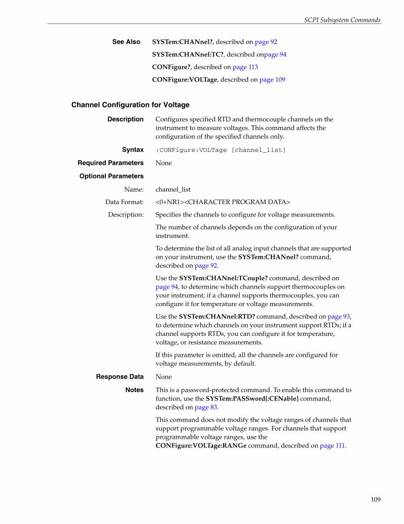
SCPI Subsystem Commands
Channel Configuration for Voltage
See Also SYSTem:CHANnel?, described on page 92
SYSTem:CHANnel:TC?, described onpage 94
CONFigure?, described on page 113
CONFigure:VOLTage, described on page 109
Description Configures specified RTD and thermocouple channels on the instrument to measure voltages. This command affects the configuration of the specified channels only.
Syntax :CONFigure:VOLTage [channel_list]
Required Parameters None
Optional Parameters
Name:
Data Format:
Description:
channel_list
<0+NR1><CHARACTER PROGRAM DATA>
Specifies the channels to configure for voltage measurements.
The number of channels depends on the configuration of your instrument.
To determine the list of all analog input channels that are supported on your instrument, use the SYSTem:CHANnel? command, described on page 92.
Use the SYSTem:CHANnel:TCouple? command, described on page 94, to determine which channels support thermocouples on your instrument; if a channel supports thermocouples, you can configure it for temperature or voltage measurements.
Use the SYSTem:CHANnel:RTD? command, described on page 93, to determine which channels on your instrument support RTDs; if a channel supports RTDs, you can configure it for temperature, voltage, or resistance measurements.
If this parameter is omitted, all the channels are configured for voltage measurements, by default.
Response Data None
Notes This is a password-protected command. To enable this command to function, use the SYSTem:PASSword[:CENable] command, described on page 83.
This command does not modify the voltage ranges of channels that support programmable voltage ranges. For channels that support programmable voltage ranges, use the CONFigure:VOLTage:RANGe command, described on page 111.
109

Chapter 4
110
Notes (cont.) A Command Error is generated if the specified channel list includes a channel number less than 0 or greater than the maximum number of supported channels. If bit 5 (CME) of the Standard Event Status Enable register is enabled, a Command Error sets bit 5 (CME) of the Standard Event Status register.
An Execution Error is generated if the instrument is scanning, that is an INITiate command was issued and was not aborted, prior to issuing this command. If bit 4 (E) of the Standard Event Status Enable register is enabled, an Execution Error sets bit 4 (E) of the Standard Event Status register.
The summary of the Standard Event Status register is available in bit 5 (ESB) of the Status Byte register.
When an error is encountered, an error string is appended to the error queue, and bit 2 (EAV) of the Status Byte register is set.
For more information, refer to 1999 SCPI Command Reference, section 3.1 and 3.7.2, and 1999 SCPI Syntax & Style, section 8.3.2.
Example The following example configures analog input channels 0, 3 through 7, and 47 for voltage measurements:
> :CONF:VOLT (@0,3:7,47)
This example configures all analog input channels for voltage measurements:
> :CONF:VOLT
This example configures analog input channels 1, 2, and 8 through 46 for voltage measurements:
> :CONF:VOLT (@1,2,8:46)
See Also SYSTem:CHANnel?, described on page 92
SYSTem:CHANnel:TCouple?, described on page 94
SYSTem:CHANnel:RTD?, described on page 93
SYSTem:CHANnel:VOLTage:RANGe?, described on page 95
CONFigure?, described on page 113
CONFigure:RESistance, described on page 103
CONFigure:TEMPerature:RTD, described on page 104
CONFigure:TEMPerature:TCouple, described on page 106
CONFigure:VOLTage:RANGe, described on page 111

SCPI Subsystem Commands
Channel Configuration for Programmable Voltage Ranges
Description For VOLTpoint and MEASURpoint LXI instruments that support programmable input ranges, configures the voltage range for specified channels on the instrument. This command affects the configuration of the specified channels only.
Syntax :CONFigure:VOLTage:RANGe {BIP100MV|BIP1V|BIP10V|BIP100V|BIP400V|BIP60V|DEFault},[<channel_list]>
Required Parameters
Name:
Data Format:
Description:
{BIP100MV|BIP1V|BIP10V|BIP100V|BIP400V||BIP60V|DEFault}
<CHARACTER PROGRAM DATA>
Specifies one of the following voltage ranges:
• BIP100MV – Specifies an input voltage range of ±0.1 V.
• BIP1V – Specifies an input voltage range of ±1 V.
• BIP10V – Specifies an input voltage range of ±10 V.
• BIP100V – Specifies an input voltage range of ±100 V.
• BIP400V – Specifies an input voltage range of ±400 V.
• BIP60V – Specifies an input voltage range of ±60 V.
• DEFault – Selects the default voltage range of ±10 V.
Note: MEASURpoint instruments currently support only the ±10 V and ±60 V ranges.
Optional Parameters
Name:
Data Format:
Description:
channel_list
<0+NR1><CHARACTER PROGRAM DATA>
Specifies the channels to configure for the specified voltage range.
The number of channels that you can specify depends on the configuration of your instrument.
To determine the list of all analog input channels that are supported on your instrument, use the SYSTem:CHANnel? command, described on page 92.
To determine the list of all analog input channels that support programmable voltage ranges on your instrument, use the SYSTem:CHANnel:VOLTage:RANGe? command, described on page 95.
Response Data None
111

Chapter 4
112
Notes This is a password-protected command. To enable this command to function, use the SYSTem:PASSword[:CENable] command, described on page 83.
A Command Error is generated if the specified channel list includes a channel number less than 0 or greater than the maximum number of supported channels. If bit 5 (CME) of the Standard Event Status Enable register is enabled, a Command Error sets bit 5 (CME) of the Standard Event Status register.
An Execution Error is generated if the instrument is scanning, that is an INITiate command was issued and was not aborted, prior to issuing this command. If bit 4 (E) of the Standard Event Status Enable register is enabled, an Execution Error sets bit 4 (E) of the Standard Event Status register.
The summary of the Standard Event Status register is available in bit 5 (ESB) of the Status Byte register.
When an error is encountered, an error string is appended to the error queue, and bit 2 (EAV) of the Status Byte register is set.
For more information, refer to 1999 SCPI Command Reference, section 3.1 and 3.7.2, and 1999 SCPI Syntax & Style, section 8.3.2.
Example On an instrument that supports programmable voltage ranges, the following example configures analog input channels 0 to 3 for a voltage range of ±10 V, and channels 4 to 7 for a voltage range of ±60 V:
>:CONF:VOLT:RANG BIP10V, (@0:3)>:CONF:VOLT:RANG BIP60V, (@4:7)>:CONF? (@0:7)< BIP10V,BIP10V,BIP10V,BIP10V,BIP60V,BIP60V,
BIP60V,BIP60V
See Also SYSTem:CHANnel?, described on page 92
SYSTem:CHANnel:TCouple?, described on page 94
SYSTem:CHANnel:RTD?, described on page 93
SYSTem:CHANnel:VOLTage:RANGe?, described on page 95
CONFigure:RESistance, described on page 103
CONFigure:TEMPerature:RTD, described on page 104
CONFigure:TEMPerature:TCouple, described on page 106
CONFigure?, described on page 113

SCPI Subsystem Commands
Channel Configuration Query
Description Returns the configuration of specified analog input channels on the instrument.
Syntax :CONFigure? [channel_list]
Required Parameters None
Optional Parameters
Name:
Data Format:
Description:
channel_list
<0+NR1>
Specifies the channels for which to return configuration information. If this parameter is omitted, the configuration of all channels is returned.
The number of supported channels depends on the configuration of your instrument.
To determine the list of all analog input channels that are supported on your instrument, use the SYSTem:CHANnel? command, described on page 92.
Use the SYSTem:CHANnel:TCouple? command, described on page 94, to determine which analog input channels on your instrument support thermocouples; if a channel supports thermocouples, you can configure it for temperature or voltage measurements.
Use the SYSTem:CHANnel:RTD? command, described on page 93, to determine which analog input channels on your instrument support RTDs; if a channel supports RTDs, you can configure it for temperature, voltage, or resistance measurements.
Response Data up to 48 fields of comma-separated values; each value belongs to an enumerated set:
<type>,<type>,<type>,....,<type>
Name:
Data Format:
Description:
type
<CHARACTER RESPONSE DATA>
The first character corresponds to the configuration of the first channel specified in channel list, the second character corresponds to the configuration of the next channel in channel list, and so on.
If a channel is configured for a fixed-range voltage input with the CONFigure:VOLTage command, V is returned.
If a channel is configured for a programmable voltage range with the CONFigure:VOLTage:RANGe command on a MEASURpoint instrument, one of the following values is returned for each channel: BIP10V or BIP60V.
If a channel is configured for a thermocouple input, one of the following thermocouple types is returned: J, K, R, S, T, B, E, or N.
113
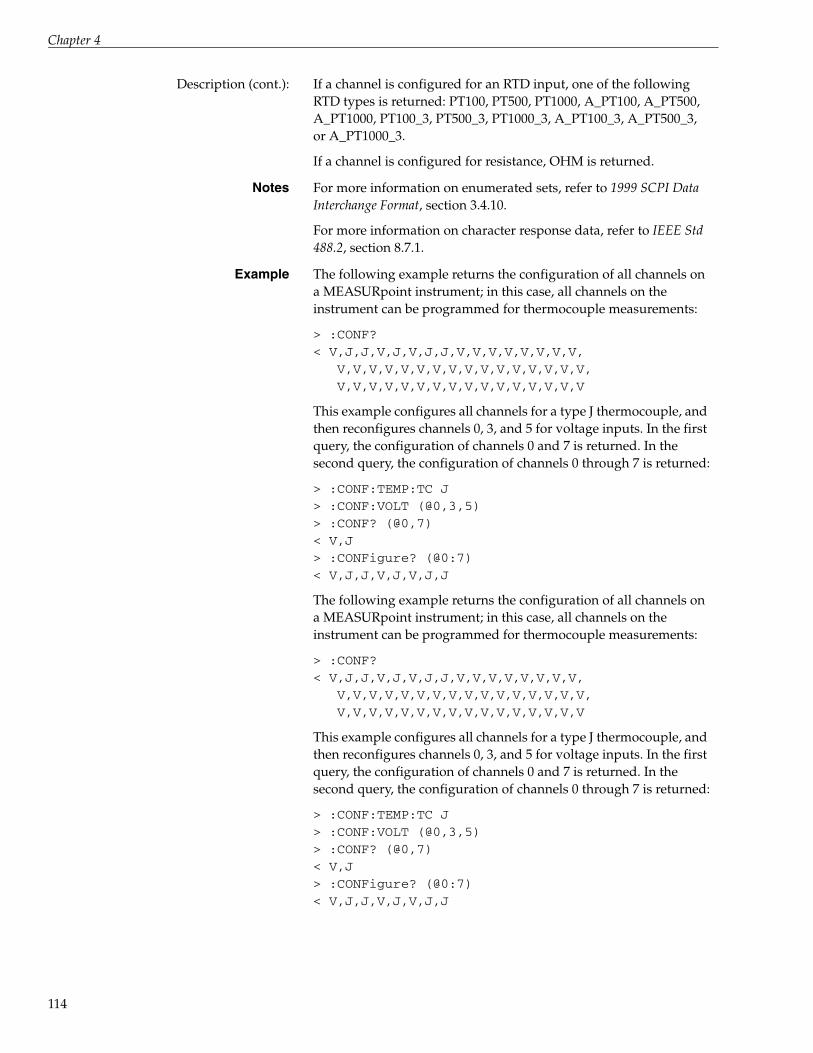
Chapter 4
114
Description (cont.): If a channel is configured for an RTD input, one of the following RTD types is returned: PT100, PT500, PT1000, A_PT100, A_PT500, A_PT1000, PT100_3, PT500_3, PT1000_3, A_PT100_3, A_PT500_3, or A_PT1000_3.
If a channel is configured for resistance, OHM is returned.
Notes For more information on enumerated sets, refer to 1999 SCPI Data Interchange Format, section 3.4.10.
For more information on character response data, refer to IEEE Std 488.2, section 8.7.1.
Example The following example returns the configuration of all channels on a MEASURpoint instrument; in this case, all channels on the instrument can be programmed for thermocouple measurements:
> :CONF?< V,J,J,V,J,V,J,J,V,V,V,V,V,V,V,V,
V,V,V,V,V,V,V,V,V,V,V,V,V,V,V,V,V,V,V,V,V,V,V,V,V,V,V,V,V,V,V,V
This example configures all channels for a type J thermocouple, and then reconfigures channels 0, 3, and 5 for voltage inputs. In the first query, the configuration of channels 0 and 7 is returned. In the second query, the configuration of channels 0 through 7 is returned:
> :CONF:TEMP:TC J> :CONF:VOLT (@0,3,5)> :CONF? (@0,7)< V,J> :CONFigure? (@0:7)< V,J,J,V,J,V,J,J
The following example returns the configuration of all channels on a MEASURpoint instrument; in this case, all channels on the instrument can be programmed for thermocouple measurements:
> :CONF?< V,J,J,V,J,V,J,J,V,V,V,V,V,V,V,V,
V,V,V,V,V,V,V,V,V,V,V,V,V,V,V,V,V,V,V,V,V,V,V,V,V,V,V,V,V,V,V,V
This example configures all channels for a type J thermocouple, and then reconfigures channels 0, 3, and 5 for voltage inputs. In the first query, the configuration of channels 0 and 7 is returned. In the second query, the configuration of channels 0 through 7 is returned:
> :CONF:TEMP:TC J> :CONF:VOLT (@0,3,5)> :CONF? (@0,7)< V,J> :CONFigure? (@0:7)< V,J,J,V,J,V,J,J

SCPI Subsystem Commands
Filter Configuration
Example (cont.) In this example, the configuration of channels 0 through 7 of a MEASURpoint instrument that supports programmable voltage ranges is returned:
> :CONF? (@0:7)< BIP10V,BIP10V,BIP60V,BIP60V,BIP60V,BIP60V,
BIP60V,BIP60V
See Also CONFigure:RESistance, described on page 103
CONFigure:TEMPerature:RTD, described on page 104
CONFigure:TEMPerature:TCouple, described on page 106
CONFigure:VOLTage, described on page 109
CONFigure:VOLTage:RANGe, described on page 111
SYSTem:CHANnel?, described on page 92
SYSTem:CHANnel:TCouple?, described on page 94
SYSTem:CHANnel:RTD?, described on page 93
SYSTem:CHANnel:VOLTage:RANGe?, described on page 95
Description Configures the filter type used for single-value and continuous analog input operations on the instrument.
Syntax :CONFigure:FILTer [{RAW|AVG}]
Required Parameters None
Optional Parameters
Name:
Data Format:
Description:
{RAW|AVG}
<CHARACTER PROGRAM DATA>
Specifies one of the following filter types:
• RAW – No filter. Provides fast response times, but the data may be difficult to interpret. Use when you want to filter the data yourself.
The RAW filter type returns the data exactly as it comes out of the Delta-Sigma A/D converters. Note that Delta-Sigma converters provide substantial digital filtering above the Nyquist frequency.
Generally, the only time it is desirable to turn off the software filter is if you are using fast responding thermocouples/RTDs, sampling them at higher speeds (> 1 Hz), and need as much response speed as possible.
115

Chapter 4
116
Filter Query
Description (cont.): • AVG – (Moving Average) Provides a compromise of filter functionality and response time. This filter can be used in any application.
This low-pass filter takes the previous 16 samples, adds them together, and divides by 16.
Response Data None
Notes This is a password-protected command. To enable this command to function, use the SYSTem:PASSword[:CENable] command, described on page 83.
An Execution Error is generated if the instrument is scanning, that is an INITiate command was issued and was not aborted, prior to issuing this command. If bit 4 (E) of the Standard Event Status Enable register is enabled, an Execution Error sets bit 4 (E) of the Standard Event Status register.
The summary of the Standard Event Status register is available in bit 5 (ESB) of the Status Byte register.
When an error is encountered, an error string is appended to the error queue, and bit 2 (EAV) of the Status Byte register is set.
Example The following examples set the filter type, and then return the current filter configuration:
> :CONF:FILT AVG> :CONF:FILT?< AVG
> :CONF:FILT RAW> :CONF:FILT?< RAW
See Also CONFigure:FILTer?, described next
CONFigure?, described on page 113
CONFigure:SCAn:LISt, described on page 120
CONFigure:SCAn:CJC, described on page 118
Description Returns the currently configured filter type for the instrument.
Syntax :CONFigure:FILTer?
Command Parameters None
Response Data <filter_type>

SCPI Subsystem Commands
Scan Circular Buffer Query
Name:
Data Format:
Description:
filter_type
<CHARACTER RESPONSE DATA>
Returns one of the following filter types:
• RAW – No filter. Provides fast response times, but the data may be difficult to interpret. Use when you want to filter the data yourself.
The RAW filter type returns the data exactly as it comes out of the Delta-Sigma A/D converters. Note that Delta-Sigma converters provide substantial digital filtering above the Nyquist frequency.
Generally, the only time it is desirable to turn off the software filter is if you are using fast responding thermocouples/RTDs, sampling them at higher speeds (> 1 Hz), and need as much response speed as possible.
• AVG – (Moving Average) Provides a compromise of filter functionality and response time. This filter can be used in any application.
This low-pass filter takes the previous 16 samples, adds them together, and divides by 16.
Example The following examples set the filter type, and then return the current configuration of the filter type:
> :CONF:FILT AVG> :CONF:FILT?< AVG
> :CONF:FILT RAW> :CONF:FILT?< RAW
See Also CONFigure:FILTer, described on page 115
CONFigure?, described on page 113
Description Returns the size of the circular buffer, in bytes, that is used to store scan data.
Syntax :CONFigure:SCAn:BUFfer[:LEN]?
Required Parameters None
Response Data <Buffer_Size>
Name:
Data Format:
Description:
Buffer_Size
<+NR1>
A decimal number that represents the size of the circular buffer on the instrument, in bytes.
117
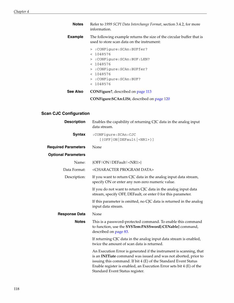
Chapter 4
118
Scan CJC Configuration
Notes Refer to 1999 SCPI Data Interchange Format, section 3.4.2, for more information.
Example The following example returns the size of the circular buffer that is used to store scan data on the instrument:
> :CONFigure:SCAn:BUFfer?< 1048576> :CONFigure:SCAn:BUF:LEN?< 1048576> :CONFigure:SCAn:BUFfer?< 1048576> :CONFigure:SCAn:BUF?< 1048576
See Also CONFigure?, described on page 113
CONFigure:SCAn:LISt, described on page 120
Description Enables the capability of returning CJC data in the analog input data stream.
Syntax :CONFigure:SCAn:CJC[{OFF|ON|DEFault|<NR1>}]
Required Parameters None
Optional Parameters
Name:
Data Format:
Description:
{OFF|ON|DEFault|<NR1>}
<CHARACTER PROGRAM DATA>
If you want to return CJC data in the analog input data stream, specify ON or enter any non-zero numeric value.
If you do not want to return CJC data in the analog input data stream, specify OFF, DEFault, or enter 0 for this parameter.
If this parameter is omitted, no CJC data is returned in the analog input data stream.
Response Data None
Notes This is a password-protected command. To enable this command to function, use the SYSTem:PASSword[:CENable] command, described on page 83.
If returning CJC data in the analog input data stream is enabled, twice the amount of scan data is returned.
An Execution Error is generated if the instrument is scanning, that is an INITiate command was issued and was not aborted, prior to issuing this command. If bit 4 (E) of the Standard Event Status Enable register is enabled, an Execution Error sets bit 4 (E) of the Standard Event Status register.
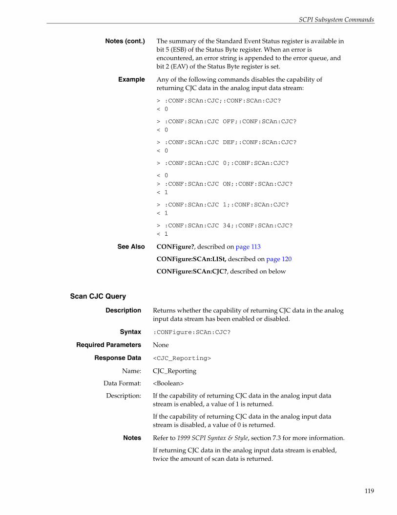
SCPI Subsystem Commands
Scan CJC Query
Notes (cont.) The summary of the Standard Event Status register is available in bit 5 (ESB) of the Status Byte register. When an error is encountered, an error string is appended to the error queue, and bit 2 (EAV) of the Status Byte register is set.
Example Any of the following commands disables the capability of returning CJC data in the analog input data stream:
> :CONF:SCAn:CJC;:CONF:SCAn:CJC?< 0
> :CONF:SCAn:CJC OFF;:CONF:SCAn:CJC?< 0
> :CONF:SCAn:CJC DEF;:CONF:SCAn:CJC?< 0
> :CONF:SCAn:CJC 0;:CONF:SCAn:CJC?
< 0> :CONF:SCAn:CJC ON;:CONF:SCAn:CJC?< 1
> :CONF:SCAn:CJC 1;:CONF:SCAn:CJC?< 1
> :CONF:SCAn:CJC 34;:CONF:SCAn:CJC?< 1
See Also CONFigure?, described on page 113
CONFigure:SCAn:LISt, described on page 120
CONFigure:SCAn:CJC?, described on below
Description Returns whether the capability of returning CJC data in the analog input data stream has been enabled or disabled.
Syntax :CONFigure:SCAn:CJC?
Required Parameters None
Response Data <CJC_Reporting>
Name:
Data Format:
Description:
CJC_Reporting
<Boolean>
If the capability of returning CJC data in the analog input data stream is enabled, a value of 1 is returned.
If the capability of returning CJC data in the analog input data stream is disabled, a value of 0 is returned.
Notes Refer to 1999 SCPI Syntax & Style, section 7.3 for more information.
If returning CJC data in the analog input data stream is enabled, twice the amount of scan data is returned.
119

Chapter 4
120
Scan List Configuration
Example Any of the following commands disables the capability of returning CJC data in the analog input data stream:
> :CONF:SCAn:CJC;:CONF:SCAn:CJC?< 0
> :CONF:SCAn:CJC OFF;:CONF:SCAn:CJC?< 0
> :CONF:SCAn:CJC DEF;:CONF:SCAn:CJC?< 0
> :CONF:SCAn:CJC 0;:CONF:SCAn:CJC?
< 0> :CONF:SCAn:CJC ON;:CONF:SCAn:CJC?< 1
> :CONF:SCAn:CJC 1;:CONF:SCAn:CJC?< 1
> :CONF:SCAn:CJC 34;:CONF:SCAn:CJC?< 1
See Also CONFigure?, described on page 113
CONFigure:SCAn:LISt, described on page 120
CONFigure:SCAn:CJC, described on page 118
Description Enables a list of channels to scan on the instrument.
Syntax :CONFigure:SCAn:LISt [channel_list]
Required Parameters None
Optional Parameters
Name:
Data Format:
Description:
channel_list
<0+NR1>
Specifies the channels to enable for scanning. The number of channels that you can enable for scanning depends on the configuration of your instrument.
To determine the list of all analog input channels that are supported on your instrument, use the SYSTem:CHANnel? command, described on page 92.

SCPI Subsystem Commands
Description (cont.): You can also read the value of the digital input port through the analog input data stream by specifying the digital input channel in the channel list. The number of the digital input channel depends on the configuration of your instrument:
Standard TEMPpoint, VOLTpoint, and MEASURpoint instruments (DT8871, DT8871U, DT8872, DT8873, DT8874):
Total # of A/D channels Channel # for DIN port0 - 7 80 - 15 160 - 23 240 - 31 320 - 39 400 - 47 48
If the channel_list parameter is omitted, all channels are disabled by default.
Response Data None
Notes This is a password-protected command. To enable this command to function, use the SYSTem:PASSword[:CENable] command, described on page 83.
A Command Error is generated if the specified channel list includes a channel number less than 0 or greater than the maximum number of supported channels. If bit 5 (CME) of the Standard Event Status Enable register is enabled, a Command Error sets bit 5 (CME) of the Standard Event Status register.
An Execution Error is generated if the instrument is scanning, that is an INITiate command was issued and was not aborted, prior to issuing this command. If bit 4 (E) of the Standard Event Status Enable register is enabled, an Execution Error sets bit 4 (E) of the Standard Event Status register.
The summary of the Standard Event Status register is available in bit 5 (ESB) of the Status Byte register.
When an error is encountered, an error string is appended to the error queue, and bit 2 (EAV) of the Status Byte register is set.
Refer to 1999 SCPI Syntax & Style, section 8.3.2, for more information.
Example This example enables channels 0, 4, 5, and 7 and then returns the list of enabled channels; note that while this command tries to enable channel 5 twice, it is enabled only once:
> :CONF:SCAn:LISt (@5,4,7,0,5)> :CONF:SCAn:LISt?< (@0,4:5,7)
121

Chapter 4
122
Scan List Query
Example (cont.) This example disables all channels; the list of enabled channels is empty:
> :CONF:SCAn:LISt> :CONF:SCAn:LISt?< (@)
This command enables channels 0, 4, 5, and 7 and returns the list of enabled channels:
> :CONF:SCAn:LISt (@5,4,7,0)> :CONF:SCAn:LISt?< (@0,4:5,7)
This command enables channels 0, 4, 5, 6, and 7 and returns the list of enabled channels:
> :CONF:SCAn:LISt (@5,4,7,6,0)> :CONF:SCAn:LISt?< (@0,4:7)
See Also CONFigure?, described on page 113
CONFigure:SCAn:LISt?, described next
Description Returns the list of channels that are enabled for scanning on the instrument.
Syntax :CONFigure:SCAn:LISt?
Parameters None
Response Data <channel_list>
Name:
Data Format:
Description:
channel_list
<0+NR1>
The list of channels that are enabled for scanning.
The number of channels that can be enabled for scanning depends on the configuration of your instrument.
To determine the list of all analog input channels that are supported on your instrument, use the SYSTem:CHANnel? command, described on page 92.
Use the SYSTem:CHANnel:TC? command, described on page 94, to determine which analog input channels on your instrument support thermocouples; if a channel supports thermocouples, you can configure it for temperature or voltage measurements.

SCPI Subsystem Commands
Scan Rate Configuration
Description (cont.): Use the SYSTem:CHANnel:RTD? command, described on page 93, to determine which analog input channels on your instrument support RTDs; if a channel supports RTDs, you can configure it for temperature, voltage, or resistance measurements.
If no channels are enabled, an empty list (@) is returned.
Example The following example enables channels 0, 4, 5, and 7 and then returns the list of enabled channels; note that while this command tries to enable channel 5 twice, it is enabled only once:
> :CONF:SCAn:LISt (@5,4,7,0,5)> :CONF:SCAn:LISt?< (@0,4:5,7)
This example disables all channels; the list of enabled channels is empty:
> :CONF:SCAn:LISt;:CONF:SCAN:LISt?< (@)
This example enables channels 0, 4, 5, and 7 and then returns the list of enabled channels:
> :CONF:SCAn:LISt (@5,4,7,0)> :CONF:SCAn:LISt?< (@0,4:5,7)
This example enables channels 0, 4, 5, 6, and 7 and then returns the list of enabled channels:
> :CONF:SCAn:LISt (@5,4,7,6,0)> :CONF:SCAn:LISt?< (@0,4:7)
See Also CONFigure?, described on page 113
CONFigure:SCAn:LISt, described on page 120
Description Configures either the time period of each scan, in the number of seconds per scan, or the scan frequency, in Hertz.
Syntax :CONFigure:SCAn:RATe[:SEC|HZ] <DECIMAL NUMERIC PROGRAM DATA>
Optional Keywords
Name:
Data Format:
Description:
SEC|HZ
<CHARACTER PROGRAM DATA>
Optional enumerated type that specifies whether to return the maximum scan rate in seconds (SEC) or the maximum scan frequency, in Hertz (HZ).
If this keyword is omitted, SEC is used by default.
123

Chapter 4
124
Required Parameters
Name:
Data Format:
Description:
<DECIMAL NUMERIC PROGRAM DATA>
<0+Numeric>
If SEC is specified or if neither SEC nor HZ is specified for the SEC|HZ keyword, enter a floating-point value (greater than 0) for the time period of each scan, in seconds. These values range from 0.1 s to 6553.5 s.
If HZ is specified for the SEC|HZ keyword, enter a floating-point value (greater than 0) for the scan frequency in Hertz. These values range from 0.000152590219 Hz to 10.0 Hz.
Response Data None
Notes This is a password-protected command. To enable this command to function, use the SYSTem:PASSword[:CENable] command, described on page 83.
The scan rate that you specify is rounded to the closest "correct" value that the instrument can accept without error.
Internally, the 10 Hz clock is divided by an integer in the range of 1 to 65535 (the clock divider) to determine the closest value. You can query this setting after programming it to determine the actual scan rate that is used.
An Execution Error is generated if the instrument is scanning, that is an INITiate command was issued and was not aborted, prior to issuing this command. If bit 4 (E) of the Standard Event Status Enable register is enabled, an Execution Error sets bit 4 (E) of the Standard Event Status register.
The summary of the Standard Event Status register is available in bit 5 (ESB) of the Status Byte register.
When an error is encountered, an error string is appended to the error queue, and bit 2 (EAV) of the Status Byte register is set.
Refer to 1999 SCPI Data Interchange Format, section 3.4.2, for more information.
Example The following command tries to set the scan frequency to 3 Hz, but the actual scan frequency is set to 3.3 Hz, which corresponds to a scan rate of 0.3 s:
> :CONF:SCAn:RATe:HZ 3> :CONF:SCAn:RATe:HZ?< 3.333333> :CONF:SCAN:RATe?< 0.300000

SCPI Subsystem Commands
Scan Rate Query
Example (cont.) The following command sets the scan frequency to 2 Hz, which corresponds to a scan rate of 0.5 s; the actual scan frequency is set to the same value, since 2 is an exact divisor of 10.0 Hz:
> :CONF:SCAn:RATe 0.5> :CONF:SCAn:RATe:HZ?< 2.000000> :CONF:SCAN:RATe?< 0.500000
In this example, an invalid scan frequency is specified, and an Execution Error occurs. If bit 4 (E) of the Standard Event Status Enable register is enabled, an Execution Error sets bit 4 (E) of the Standard Event Status register. This, in turn, sets bits 2 and 5 of the Status Byte register:
> :CONF:SCAn:RATe:HZ 200> *STB?< 36> *ESR?< 16> *STB?< 4> :SYST:ERR?< -222,"Data out of range; CONF:SCAn:RATe"> *STB?
< 0
See Also SYSTem:SCAn:RATe:MIN?, described on page 98
SYSTem:SCAn:RATe:MAX?, described on page 97
CONFigure?, described on page 113
CONFigure:SCAn:RATe?, described next
Description Returns either the time period of each scan, in the number of seconds per scan, or the scan frequency, in Hertz.
Syntax :CONFigure:SCAn:RATe[:SEC|HZ]?
Optional Keywords
Name:
Data Format:
Description:
SEC|HZ
<CHARACTER PROGRAM DATA>
Optional enumerated type that specifies whether to return the maximum scan rate in seconds (SEC) or the maximum scan frequency, in Hertz (HZ).
If this keyword is omitted, SEC is used by default.
Parameters None
125

Chapter 4
126
Response Data <DECIMAL NUMERIC PROGRAM DATA>
Name:
Data Format:
Description:
<DECIMAL NUMERIC PROGRAM DATA>
<0+Numeric>
If you specified SEC or omitted the SEC|HZ keyword in the command, returns a floating-point value that represents the time period of each scan, in seconds. These values range from 0.1 s to 6553.5 s.
If you specified the HZ keyword in the command, returns a floating-point value that represents the scan frequency, in Hertz. These values range from 0.000152590219 Hz to 10.0 Hz.
Example The following command tries to set the scan frequency to 3 Hz, but the actual scan frequency is set to 3.3 Hz, which corresponds to a scan rate of 0.3 s:
> :CONF:SCAn:RATe:HZ 3> :CONF:SCAn:RATe:HZ?< 3.333333> :CONF:SCAN:RATe?< 0.300000
The following command sets the scan frequency to 2 Hz, which corresponds to a scan rate of 0.5 s; the actual scan frequency is set to the same value, since 2 is an exact divisor of 10.0 Hz:
> :CONF:SCAn:RATe 0.5> :CONF:SCAn:RATe:HZ?< 2.000000> :CONF:SCAN:RATe?< 0.500000
In this example, an invalid scan frequency is specified and an Execution Error occurs. If bit 4 (E) of the Standard Event Status Enable register is enabled, an Execution Error sets bit 4 (E) of the Standard Event Status register. This, in turn, sets bits 2 and 5 of the Status Byte register:
> :CONF:SCAn:RATe:HZ 200> *STB?< 36> *ESR?< 16> *STB?< 4> :SYST:ERR?< -222,"Data out of range; CONF:SCAn:RATe"> *STB?< 0

SCPI Subsystem Commands
Trigger Source Configuration
See Also CONFigure?, described on page 113
CONFigure:SCAn:RATe, described on page 123
SYSTem:SCAn:RATe:MIN?, described on page 98
SYSTem:SCAn:RATe:MAX?, described on page 97
Description Configures the trigger source used to start the analog input operation once the INITiate command, described on page 140, is executed.
Syntax :CONFigure:TRIGger[:SOURce] {IMMediate|DIN0|DEFault}
Required Parameters
Name:
Data Format:
Description:
{IMMediate|DIN0|DEFault}
<CHARACTER PROGRAM DATA>
Specifies one of the following trigger sources:
• IMMediate – Specifies a software trigger. When the INITiate command is executed, acquisition starts immediately.
• DIN0 – Specifies an external, digital trigger on digital input line 0. When the INITiate command is executed, acquisition does not start until the instrument detects a 3 to 28 V DC signal on digital input line 0.
Initially, the external signal must be low and then go high for at least 100 ms to be detected as a trigger. Once triggered, the state of digital input 0 is ignored.
If DEFault is specified, the IMMediate (software) trigger is used by default.
Notes This is a password-protected command. To enable this command to function, use the SYSTem:PASSword[:CENable] command, described on page 83.
To terminate an operation that was started with INITiate, regardless of whether the trigger occurred or not, use the ABORt command, described on page 143.
Response Data None
Example The following command sets the trigger source to the external, digital trigger:
> :CONF:TRIG DIN0
See Also CONFigure:TRIGger[:SOURce]?, described next
127

Chapter 4
128
Trigger Source Query
Description Returns the currently configured trigger source for the instrument.
Syntax :CONFigure:TRIGger[:SOURce]?
Parameters None
Response Data {IMMediate|DIN0}
Name:
Data Format:
Description:
{IMMediate|DIN0}
<CHARACTER RESPONSE DATA>
Returns one of the following trigger sources:
• IMMediate – A software trigger is configured. When the INITiate command is executed, acquisition starts immediately.
• DIN0 – Specifies an external, digital trigger on digital input line 0. When the INITiate command is executed, acquisition does not start until the instrument detects a 3 to 28 V DC signal on digital input line 0.
Initially, the external signal must be low and then go high for at least 100 ms to be detected as a trigger. Once triggered, the state of digital input 0 is ignored.
Example The following returns the currently configured trigger source of the instrument; in this case, an external digital trigger is configured:
> :CONF:TRIG?< DIN0
See Also CONFigure:TRIGger[:SOURce], described on page 127
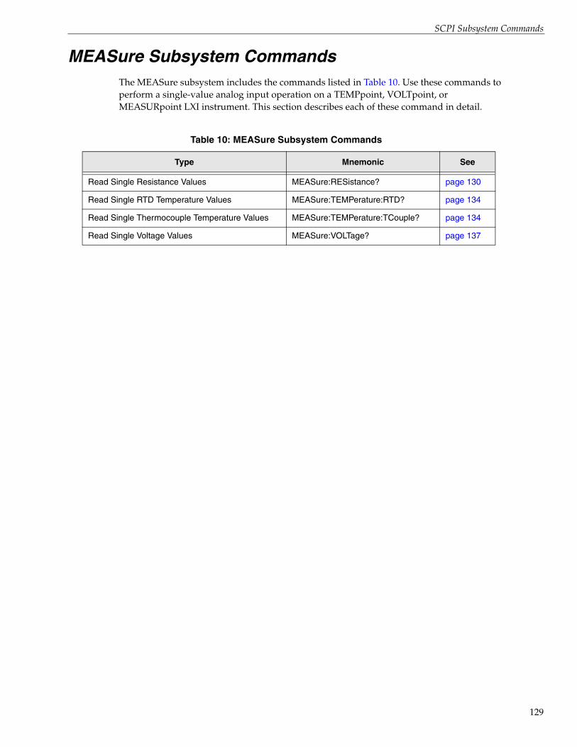
SCPI Subsystem Commands
MEASure Subsystem CommandsThe MEASure subsystem includes the commands listed in Table 10. Use these commands to perform a single-value analog input operation on a TEMPpoint, VOLTpoint, or MEASURpoint LXI instrument. This section describes each of these command in detail.
Table 10: MEASure Subsystem Commands
Type Mnemonic See
Read Single Resistance Values MEASure:RESistance? page 130
Read Single RTD Temperature Values MEASure:TEMPerature:RTD? page 134
Read Single Thermocouple Temperature Values MEASure:TEMPerature:TCouple? page 134
Read Single Voltage Values MEASure:VOLTage? page 137
129
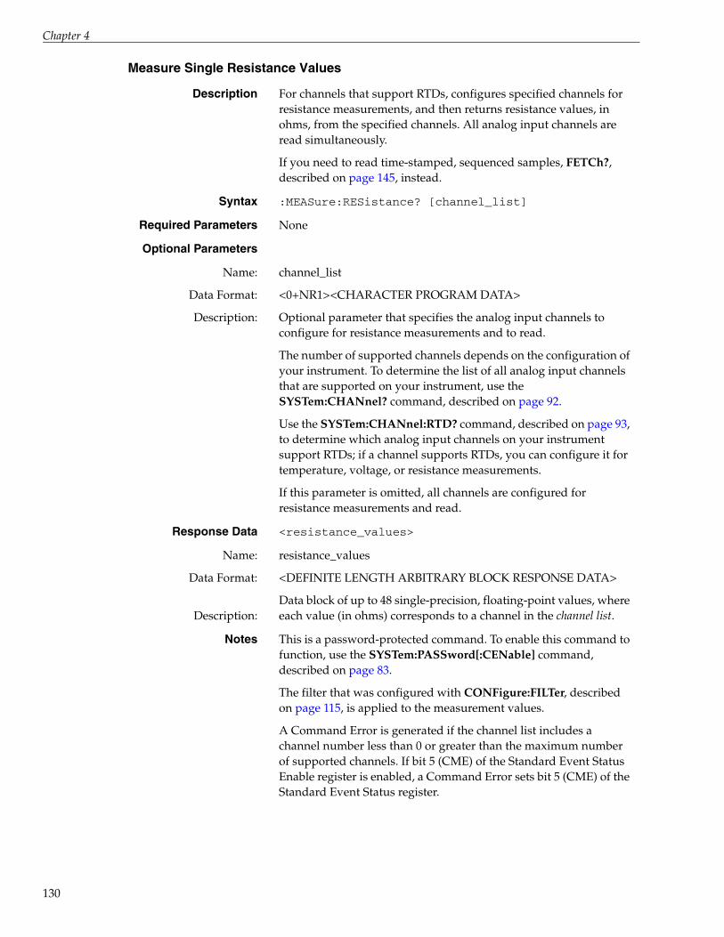
Chapter 4
130
Measure Single Resistance Values
Description For channels that support RTDs, configures specified channels for resistance measurements, and then returns resistance values, in ohms, from the specified channels. All analog input channels are read simultaneously.
If you need to read time-stamped, sequenced samples, FETCh?, described on page 145, instead.
Syntax :MEASure:RESistance? [channel_list]
Required Parameters None
Optional Parameters
Name:
Data Format:
Description:
channel_list
<0+NR1><CHARACTER PROGRAM DATA>
Optional parameter that specifies the analog input channels to configure for resistance measurements and to read.
The number of supported channels depends on the configuration of your instrument. To determine the list of all analog input channels that are supported on your instrument, use the SYSTem:CHANnel? command, described on page 92.
Use the SYSTem:CHANnel:RTD? command, described on page 93, to determine which analog input channels on your instrument support RTDs; if a channel supports RTDs, you can configure it for temperature, voltage, or resistance measurements.
If this parameter is omitted, all channels are configured for resistance measurements and read.
Response Data <resistance_values>
Name:
Data Format:
Description:
resistance_values
<DEFINITE LENGTH ARBITRARY BLOCK RESPONSE DATA>
Data block of up to 48 single-precision, floating-point values, where each value (in ohms) corresponds to a channel in the channel list.
Notes This is a password-protected command. To enable this command to function, use the SYSTem:PASSword[:CENable] command, described on page 83.
The filter that was configured with CONFigure:FILTer, described on page 115, is applied to the measurement values.
A Command Error is generated if the channel list includes a channel number less than 0 or greater than the maximum number of supported channels. If bit 5 (CME) of the Standard Event Status Enable register is enabled, a Command Error sets bit 5 (CME) of the Standard Event Status register.
SCPI Subsystem Commands
Measure Single RTD Temperature Values
Notes (cont.) An Execution Error is generated if the instrument is scanning, that is an INITiate command was issued and was not aborted, prior to issuing this command. If bit 4 (E) of the Standard Event Status Enable register is enabled, an Execution Error sets bit 4 (E) of the Standard Event Status register.
The summary of the Standard Event Status register is available in bit 5 (ESB) of the Status Byte register.
When an error is encountered, an error string is appended to the error queue, and bit 2 (EAV) of the Status Byte register is set.
For more information on measurements, see 1999 SCPI Command Reference, section 3.1 and 3.4. For more information on <DEFINITE LENGTH ARBITRARY BLOCK RESPONSE DATA>, see IEEE Std 488.2-1992, section 8.7.9.
Example The following example configures analog input channels 0 for a resistance measurement and reads the resistance value from this channel:
> :MEAS:RES? (@0)< 2331344488fe4f0a
where:
• 23 = ’#’ denotes the start of the block response
• 31 = ’1’ is the length of the decimal number for the block length
• 34 = ’4’ is the block length (that is 4-bytes per channel)
• 4488fe4f = 1095.947 ohms; this is the resistance measurement value from channel 0
• 0a = carriage return; this is the standard ASCII terminator
See Also CONFigure:FILTer, described on page 115
CONFigure?, described on page 113
CONFigure:RESistance, described on page 103
SYSTem:CHANnel:RTD?, described on page 93
INITiate, described on page 140
Description Configures specified channels for RTD measurements and returns temperature values, in degrees Celsius, from the specified channels. All analog input channels are read simultaneously.
If you need to read time-stamped, sequenced samples, use FETCh?, described on page 145, instead.
131

Chapter 4
132
Syntax :MEASure:TEMPerature:RTD?{PT100|PT500|PT1000|A_PT100|A_PT500|A_PT1000|PT100_3|PT500_3|PT1000_3|A_PT100_3|A_PT500_3|A_PT1000_3|DEFault} [, <channel_list>]
Required Parameters
Name:
Data Format:
Description:
{PT100|PT500|PT1000|A_PT100|A_PT500|A_PT1000|PT100_3|PT500_3|PT1000_3|A_PT100_3|A_PT500_3|A_PT1000_3|DEFault}
<CHARACTER PROGRAM DATA>
Enumerated type that specifies one of the following RTD types: PT100, PT500, or PT1000 for 2- or 4- wire European RTDs, A_PT100, A_PT500, or A_PT1000 for 2- or 4-wire American RTDs, PT100_3, PT500_3, or PT1000_3 for 3-wire European RTDs, or A_PT100_3, A_PT500_3, or A_PT1000_3 for 3-wire American RTDs.
If DEFault is specified, the PT100 RTD type is used by default.
Optional Parameters
Name:
Data Format:
Description:
channel_list
<0+NR1><CHARACTER PROGRAM DATA>
Optional parameter that specifies the analog input channels to configure and read for RTD temperature measurements.
The number of supported channels depends on the configuration of your instrument.
To determine the list of all analog input channels that are supported on the instrument, use the SYSTem:CHANnel? command, described on page 92.
Use the SYSTem:CHANnel:RTD? command, described on page 93, to determine which analog input channels on the instrument support RTDs; if a channel supports RTDs, you can configure it for temperature, voltage, or resistance measurements.
If this parameter is omitted, all channels are configured for RTD temperature measurements and read. If a channel does not support thermocouples, error –221, "Settings conflict" is generated.
Response Data <temperature_values>
Name:
Data Format:
Description:
temperature_values
<DEFINITE LENGTH ARBITRARY BLOCK RESPONSE DATA>
Data block of up to 48 single-precision, floating-point values, where each value (in degrees Celsius) corresponds to a channel in the channel list.

SCPI Subsystem Commands
Notes This is a password-protected command. To enable this command to function, use the SYSTem:PASSword[:CENable] command, described on page 83.
The filter that was configured with CONFigure:FILTer, described on page 115, is applied to the measurement values.
A Command Error is generated if one of the following conditions occurs:
• A sensor type is specified and it is either RTD for thermocouple measurement instruments or TCouple for a RTD measurement instruments
• A transducer type is specified and it is not one of the enumerated types
• The channel list includes a channel number less than 0 or greater than 47
If bit 5 (CME) of the Standard Event Status Enable register is enabled, a Command Error sets bit 5 (CME) of the Standard Event Status register.
An Execution Error is generated if one of these conditions occurs:
• The instrument is scanning, that is an INITiate command was issued and was not aborted prior to issuing this command.
• One of the following RTD types was specified for a thermocouple measurement instrument: PT100, PT500, PT1000, A_PT100, A_PT500, A_PT1000, PT100_3, PT500_3, PT1000_3, A_PT100_3, A_PT500_3, or A_PT1000_3.
• One of the following thermocouple types was specified for an RTD measurement instrument: J, K, B, E, N, R, S, or T.
If bit 4 (E) of the Standard Event Status Enable register is enabled, an Execution Error sets bit 4 (E) of the Standard Event Status register.
The summary of the Standard Event Status register is available in bit 5 (ESB) of the Status Byte register.
When an error is encountered, an error string is appended to the error queue, and bit 2 (EAV) of the Status Byte register is set.
For more information on measurements, see 1999 SCPI Command Reference, section 3.1 and 3.4. For more information on <DEFINITE LENGTH ARBITRARY BLOCK RESPONSE DATA>, see IEEE Std 488.2-1992, section 8.7.9.
133
Chapter 4
134
Measure Single Thermocouple Temperature Values
Example The following example configures analog input channels 0, 1, 7 for the default sensor and transducer type for the instrument and then reads the temperature from these channels:
> :MEAS:TEMP:RTD? DEF,(@0,1,7)< 23323132c7ad9c0041bd99b647c34f800a
where:
• 23 = ’#’ denotes the start of the block response
• 32 = ’2’ is the length of the decimal number for the block length
• 3132 = ’12’ is the block length (that is 4-bytes per channel times 3)
• c7ad9c00 = –88888° C; this is the measurement value from channel 0, indicating that the value is too low and out of range
• 41bd99b6 = 27.7° C; this is the measurement value from channel 1
• 47c34f80 = 99999° C; this is the measurement value from channel 7
• 0a = carriage return; this is the standard ASCII terminator
See Also CONFigure:FILTer, described on page 115
CONFigure?, described on page 113
CONFigure:TEMPerature:RTD, described on page 104
INITiate, described on page 140
Description Configures specified channels for thermocouple measurements and returns temperature values, in degrees Celsius, from the specified channels. All analog input channels are read simultaneously.
If you need to read time-stamped, sequenced samples, use FETCh?, described on page 145, instead.
Syntax :MEASure:TEMPerature:TCouple? {J,|K|B|E|N|R|S|T|DEFault}[, <channel_list>]
Required Parameters
Name:
Data Format:
Description:
{J|K|B|E|N|R|S|T|DEFault}
<CHARACTER PROGRAM DATA>
Enumerated type that specifies one of the following thermocouple types: J, K, B, E, N, R, S, T.
If DEFault is specified, the J thermocouple type is used by default.

SCPI Subsystem Commands
Optional Parameters
Name:
Data Format:
Description:
channel_list
<0+NR1><CHARACTER PROGRAM DATA>
Optional parameter that specifies the analog input channels to configure and read for thermocouple temperature measurements.
The number of supported channels depends on the configuration of the instrument.
To determine the list of all analog input channels that are supported on the instrument, use the SYSTem:CHANnel? command, described on page 92.
Use the SYSTem:CHANnel:TCouple? command, described on page 94, to determine which analog input channels on the instrument support thermocouples; if a channel supports thermocouples, you can configure it for temperature or voltage measurements.
If this parameter is omitted, all channels are configured for temperature measurements and read. If a channel does not support thermocouples, error –221, "Settings conflict" is generated.
Response Data <temperature_values>
Name:
Data Format:
Description:
temperature_values
<DEFINITE LENGTH ARBITRARY BLOCK RESPONSE DATA>
Data block of up to 48 single-precision, floating-point values, where each value (in degrees Celsius) corresponds to a channel in the channel list.
Notes This is a password-protected command. To enable this command to function, use the SYSTem:PASSword[:CENable] command, described on page 83.
The filter that was configured with CONFigure:FILTer, described on page 115, is applied to the measurement values.
A Command Error is generated if one of the following conditions occurs:
• A sensor type is specified and it is either RTD for thermocouple measurement instruments or TCouple for a RTD measurement instruments
• A transducer type is specified and it is not one of the enumerated types
• The channel list includes a channel number less than 0 or greater than 47
If bit 5 (CME) of the Standard Event Status Enable register is enabled, a Command Error sets bit 5 (CME) of the Standard Event Status register.
135

Chapter 4
136
Notes (cont.) An Execution Error is generated if one of these conditions occurs:
• The instrument is scanning, that is an INITiate command was issued and was not aborted prior to issuing this command.
• One of the following RTD types was specified for a thermocouple measurement instrument: PT100, PT500, PT1000, A_PT100, A_PT500, A_PT1000, PT100_3, PT500_3, PT1000_3, A_PT100_3, A_PT500_3, or A_PT1000_3.O
• One of the following thermocouple types was specified for an RTD measurement instrument: J, K, B, E, N, R, S, or T.
If bit 4 (E) of the Standard Event Status Enable register is enabled, an Execution Error sets bit 4 (E) of the Standard Event Status register.
The summary of the Standard Event Status register is available in bit 5 (ESB) of the Status Byte register.
When an error is encountered, an error string is appended to the error queue, and bit 2 (EAV) of the Status Byte register is set.
For more information on measurements, see 1999 SCPI Command Reference, section 3.1 and 3.4. For more information on <DEFINITE LENGTH ARBITRARY BLOCK RESPONSE DATA>, see IEEE Std 488.2-1992, section 8.7.9.
Example The following example configures analog input channels 0, 1, 7 for the default sensor and transducer type for the instrument and then reads the temperature from these channels:
> :MEAS:TEMP:TC? DEF,(@0,1,7)< 23323132c7ad9c0041bd99b647c34f800a
where:
• 23 = ’#’ denotes the start of the block response
• 32 = ’2’ is the length of the decimal number for the block length
• 3132 = ’12’ is the block length (that is 4-bytes per channel times 3)
• c7ad9c00 = –88888° C; this is the measurement value from channel 0, indicating that the value is too low and out of range
• 41bd99b6 = 27.7° C; this is the measurement value from channel 1
• 47c34f80 = 99999° C; this is the measurement value from channel 7, indicating that an open thermocouple exists on that channel
• 0a = carriage return; this is the standard ASCII terminator
SCPI Subsystem Commands
Measure Single Voltage Values
See Also CONFigure:FILTer, described on page 115
CONFigure?, described on page 113
CONFigure:TEMPerature:TCouple, described on page 106
INITiate, described on page 140
Description Configures specified channels for voltage measurements, and then returns voltage values from the specified channels. All analog input channels are read simultaneously.
If you need to read time-stamped, sequenced samples, use FETCh?, described on page 145, instead.
Syntax :MEASure:VOLTage? [channel_list]
Required Parameters None
Optional Parameters
Name:
Data Format:
Description:
channel list
<0+NR1><CHARACTER PROGRAM DATA>
Optional parameter that specifies the analog input channels to configure for voltage measurements and to read.
The number of supported channels depends on the configuration of the instrument. To determine the list of all analog input channels that are supported on the instrument, use the SYSTem:CHANnel? command, described on page 92.
Use the SYSTem:CHANnel:TC? command, described on page 94, to determine which analog input channels on the instrument support thermocouples; if a channel supports thermocouples, you can configure it for temperature or voltage measurements.
Use the SYSTem:CHANnel:RTD? command, described on page 93, to determine which analog input channels on your instrument support RTDs; if a channel supports RTDs, you can configure it for temperature, voltage, or resistance measurements.
If this parameter is omitted, all channels are configured for voltage measurements and read.
Response Data <voltage_values>
Name:
Data Format:
Description:
voltage_values
<DEFINITE LENGTH ARBITRARY BLOCK RESPONSE DATA>
Data block of up to 48 single-precision, floating-point values, where each value corresponds to a channel in the channel list.
137

Chapter 4
138
Notes This is a password-protected command. To enable this command to function, use the SYSTem:PASSword[:CENable] command, described on page 83.
For channels that support programmable input range, the voltage ranges that were configured with CONFigure:VOLTage:RANGe, described on page 111, is applied to the measurement values.
The filter that was configured with CONFigure:FILTer, described on page 115, is also applied to the measurement values.
A Command Error is generated if the channel list includes a channel number less than 0 or greater than the maximum number of channels. If bit 5 (CME) of the Standard Event Status Enable register is enabled, Command Error sets bit 5 (CME) of the Standard Event Status register.
An Execution Error is generated if the instrument is scanning, that is an INITiate command was issued and was not aborted, prior to issuing this command. If bit 4 (E) of the Standard Event Status Enable register is enabled, an Execution Error sets bit 4 (E) of the Standard Event Status register.
A summary of the Standard Event Status register is available in bit 5 (ESB) of the Status Byte register.
When an error is encountered, an error string is appended to the error queue, and bit 2 (EAV) of the Status Byte register is set.
For more information on measurements, see 1999 SCPI Command Reference, section 3.1 and 3.4. For more information on <DEFINITE LENGTH ARBITRARY BLOCK RESPONSE DATA>, see IEEE Std 488.2-1992, section 8.7.9.
Example The following example configures analog input channels 0, 1, 7 for voltage measurements and then reads the values from these channels:
> :MEAS:VOLT? (@0,1,7)< 233231323f0f8aec3edefa51bf2844b80a
where:
• 23 = ’#’ denotes the start of the block response
• 32 = ’2’ is the length of the decimal number for the block length
• 3132 = ’12’ is the block length (that is 4-bytes per channel times 3)
• 3f0f8aec = 0.56071 V; this is the measurement value from channel 0
• 3edefa51 = 0.43550 V; this is the measurement value from channel 1
SCPI Subsystem Commands
Example (cont.) • bf2844b8 = –0.65729 V; this is the measurement value from channel 7
• 0a = carriage return; this is the standard ASCII terminator
See Also CONFigure:FILTer, described on page 115
CONFigure?, described on page 113
CONFigure:VOLTage, described on page 109
INITiate, described on page 140
SYSTem:CHANnel?, described on page 92
SYSTem:CHANnel:TCouple?, described on page 94
SYSTem:CHANnel:RTD?, described on page 93
139

Chapter 4
140
INITiate Subsystem CommandThe INITiate subsystem includes the INITiate Scan command, described below, that starts a timed scan on the TEMPpoint, VOLTpoint, or MEASURpoint LXI instrument.
INITiate Scan
Description Initiates a continuous scan operation on a instrument using the configured channels, scan list, scan rate, and trigger source.
Acquisition starts when the configured trigger source is detected.
Syntax :INITiate
Parameters None
Response Data None
Notes This is a password-protected command. To enable this command to function, use the SYSTem:PASSword[:CENable] command, described on page 83.
For information on configuring channels for voltage, refer to page 109. For information on configuring channels for resistance, refer to page 103. For information on configuring channels for RTD temperatures, refer to page 104. For information on configuring channels for thermocouple temperature measurements, refer to page 106.
For information on configuring the scan list, refer to page 120 and page 118. For information on configuring the scan rate, refer to page 123.
For information on specifying the trigger source, refer to page 127.
This command does not affect the MEASure:RESistance? query (described on page 130), MEASure:TEMPerature:RTD? query (described on page 131), MEASure:TEMPerature:TCouple? query (described on page 134), or MEASure:VOLTage? query (described on page 137).
To terminate an operation that was started with INITiate, regardless of whether the specified trigger occurred or not, use the ABORt command, described on page 143.
An Execution Error is generated by this command if one of the following conditions occurs:
• The instrument is already scanning
• No channels are enabled for scanning in the channel list
• The scan rate is invalid
If bit 4 (E) of the Standard Event Status Enable register is enabled, an Execution Error sets bit 4 (E) of the Standard Event Status register.

SCPI Subsystem Commands
Notes (cont.) To determine if an Execution Error occurred, query bit 4 of the Standard Event Status register using the *ESR? command, described on page 57.
Use the STATus:OPERation? command to query bits 4 and 5 of the Operation Status register to determine whether a scan is in progress or the instrument is waiting for a trigger. Refer to page 71 for information on the STATus:OPERation? command.
To read measurements, use the FETCh? command, described on page 145.
Example The following example configures the instrument to scan channels 0 to 5 at approximately 2 Hz when an external digital trigger is detected, and queries the Operation Status register to verify that a scan operation is not in process:
> :CONF:SCA:LIS?< (@)>:CONF:SCA:LIS (@0:5)>:CONF:TRIG IMM> :CONF:SCA:RAT:HZ 2> :CONF:SCA:RAT:HZ?< 1.875000> :STAT:OPER:COND?< 0
The scan is then initiated, and bit 7 of the Status Byte register and the Operation Status register are queried to determine the status of the scan and whether the instrument has detected the trigger:
> :INIT> *STB?< 128> :STAT:OPER:COND?< 48
In this case, the scan has started, and the instrument is waiting for the trigger. The next query confirms that the trigger occurred and the instrument is scanning:
> *STB?< 128> :STAT:OPER:COND?< 16
The scan is then stopped and bit 7 of the Status Byte register and the Operation Status register are cleared:
> :ABOR> :STAT:OPER:COND?< 0> *STB?< 0
141

Chapter 4
142
See Also ABORt, described on page 143
STATus:OPERation:CONDition?, described on page 69
CONFigure:RESistance, described on page 103
CONFigure:TEMPerature:RTD, described on page 104
CONFigure:TEMPerature:TCouple, described on page 106
CONFigure:VOLTage, described on page 109
CONFigure:SCan:CJC, described on page 118
CONFigure:SCAn:LISt, described on page 120
CONFigure:SCAn:RATe, described on page 123
CONFigure:TRIGger[:SOURce], described on page 127
FETCh?, described on page 145

SCPI Subsystem Commands
ABORt Subsystem CommandThe ABORt subsystem includes the ABORt Scan command, described below, that stops a scan on the TEMPpoint, VOLTpoint, or MEASURpoint LXI instrument, if it is in progress.
ABORt Scan
Description Stops a scan operation on the instrument, if it is in progress, regardless of whether the specified trigger occurred or not.
Syntax :ABORt
Parameters None
Response Data None
Notes This is a password-protected command. To enable this command to function, use the SYSTem:PASSword[:CENable] command, described on page 83.
This command does not affect the MEASure:RESistance? query (described on page 130), MEASure:TEMPerature:RTD? query (described on page 131), MEASure:TEMPerature:TCouple? query (described on page 134), or MEASure:VOLTage? command (described on page 137).
Use the STATus:OPERation? command to query bits 4 and 5 of the Operation Status register to determine whether a scan is in progress or the instrument is waiting for a trigger. Refer to page 71 for information on the STATus:OPERation? command.
Example The following example configures the instrument to scan channels 0 to 5 at approximately 2 Hz when a software trigger is detected and queries the Operation Status register to verify that scans are stopped:
> :CONF:SCA:LIS?< (@)> :CONF:SCA:LIS (@0:5)> :CONF:TRIG IMM> :CONF:SCA:RAT:HZ 2> :CONF:SCA:RAT:HZ?< 1.875000> :STAT:OPER:COND?< 0
The scan is then started, and bit 7 of the Status Byte register the Operation Status register are queried to determine the status of the scan:
> :INIT> *STB?< 128> :STAT:OPER:COND?< 16
143

Chapter 4
144
Example (cont.) The scan is then stopped and bit 7 of the Status Byte register and the Operation Status register are cleared:
> :ABOR> :STAT:OPER:COND?< 0> *STB?< 0
See Also INITiate, described on page 140
STATus:OPERation:CONDition?, described on page 69

SCPI Subsystem Commands
FETCh Subsystem CommandThe FETCh subsystem includes the FETCh? command, described next. Use this command to return scan records from the circular buffer on the instrument. Refer to page 44 for conceptual information, including examples, about using the FETCh? command.
FETCh Data
Description For scans that were started using the INITiate command, described on page 140, returns a number of time-stamped, sequenced measurements from the circular buffer on the instrument, in the form of scan records.
Syntax :FETCh? <RequestedScansIndex> [, RequestedScansToRead]
Required Parameters
Name:
Data Format:
Description:
RequestedScansIndex
<0+NR1>
Specifies the index of the scan record (the offset in the circular buffer) from which to retrieve data.
To read the first scan record in the circular buffer, specify 1 for RequestedScansIndex.
To request all of the data in the circular buffer (limited by the network packet size), set the RequestedScansIndex to 0 and omit the RequestedScansToRead parameter.
To read a sequence of measurements that chronologically follow the sequence of measurements from an earlier FETCh?, specify a RequestedScansIndex that is one greater than the number of the last scan record, returned by the previous FETCh? command, or that is one greater the EndingIndex, returned by the STATus:SCAn? command, described on page 74.
If only a subset of the scan records that you requested are available (either because the scan is not yet complete or the scan location in the circular buffer was overwritten with a later scan record), the instrument returns the scan records that exist between the starting index (RequestedScansIndex) and the ending index (RequestedScansIndex+RequestedScansToRead).
For example, assume that you want to read 10 scan records starting at index 5, but the scan records at indices 5 through 8 have been overwritten. In this case, FETCh? 5, 10 returns only scan records 9 through 15.
If no scan records exist between the starting index and the ending index, an empty SCAN_RECORD structure is returned.
145

Chapter 4
146
Optional Parameters
Name:
Data Format:
Description:
RequestedScansToRead
<+NR1>
An optional parameter that specifies the number of scans to retrieve from the circular buffer, starting with the index specified by RequestedScansIndex.
If this parameter is omitted, all scans currently in the circular buffer are returned (limited by the network packet size).
Response Data <SCAN_RECORD>
Name:
Data Format:
Description:
SCAN_RECORD
<DEFINITE LENGTH ARBITRARY BLOCK RESPONSE DATA>
Data block with a sequence of consecutive SCAN_RECORD structures (<SCAN_RECORD><SCAN_RECORD>...<SCAN_RECORD>), described on page 176. The scan records are chronologically ordered from the oldest to the most recent. The unit of measurement for each channel depends on its configuration (VOLTage is measured in volts, RESistance in ohms, and TEMPerature in degrees Celsius).
Notes A client can repeatedly issue a FETCh? request; however, be aware that the network traffic is high and that the client has to determine if there is any chronological overlap between responses.
Use the STATus:SCAn? command, described on page 74, to determine the starting index and the ending index of the available scan records in the circular buffer.
An Execution Error is generated if one of the following conditions occurs:
• There are no measurements in the instrument’s circular buffer
• The RequestedScansIndex is invalid
If bit 4 (E) of the Standard Event Status Enable register is enabled, an Execution Error sets bit 4 (E) of the Standard Event Status register.
The summary of the Standard Event Status register is available in bit 5 (ESB) of the Status Byte register.
When an error is encountered, an error string is appended to the error queue, and bit 2 (EAV) of the Status Byte register is set.
For more information on measurements, see 1999 SCPI Command Reference, section 3.1 and 3.4. For more information on <DEFINITE LENGTH ARBITRARY BLOCK RESPONSE DATA>, see IEEE Std 488.2-1992, section 8.7.9.

SCPI Subsystem Commands
Example 1 The following example returns scan records, starting with index 0, on an instrument that has one channel (channel 0) enabled in the scan list; note that the comments are shown in blue:
> :FETC? 0 < 23 ASCII # char that starts the IEEE block34 ASCII 4, meaning that the next 4 chars are the
length of the IEEE block32303430 ASCII character 2040, representing the
length of the entire IEEE block4a806d65 Scan record time stamp, in seconds00000000 Scan record time stamp, in milliseconds00000001 Scan record scan number (1)00000001 Scan record number of values; 1 floating
point value per scan3a86c3ff Value of chan 0 in floating-point
6.5565103e-4 (use http://babbage.cs.qc.edu/IEEE-754/32bit.html for help converting)
4a806d65 Time stamp of next record, in seconds00000064 Time stamp, in milliseconds00000002 Scan number (2)00000001 Number of values (1)3a9a4bff Value of chan 0
4a806d65 Timestamp of next record, in seconds000000c8 Time stamp, in milliseconds00000003 Scan number (3)00000001 Number of values (1)3ac543ff Value of chan 0 ...4a806d6c Timestamp of next record, in seconds00000064 Time stamp, in milliseconds00000048 Scan number (48)00000001 Number of values (1)3a5ea800 Value of chan 0
Example 2 This example returns two scan records (5 and 6) from an instrument that is scanning one channel:
> STATus:SCAn?< 1,1083> FETCh? 5, 2 (fetch records 5 and 6)23 ASCII # char that starts the IEEE block34 ASCII 4, meaning that the next 4 chars are the
length of the IEEE block30303430 ASCII character 0040, the length of the
entire IEEE block (10 4-byte fields)
147
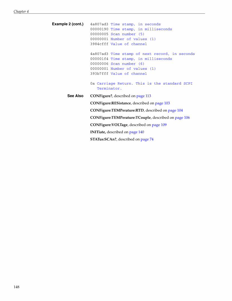
Chapter 4
148
Example 2 (cont.) 4a807ad3 Time stamp, in seconds00000190 Time stamp, in milliseconds00000005 Scan number (5)00000001 Number of values (1)3984cfff Value of channel
4a807ad3 Time stamp of next record, in seconds000001f4 Time stamp, in milliseconds00000006 Scan number (6)00000001 Number of values (1)393b7fff Value of channel
0a Carriage Return. This is the standard SCPI Terminator.
See Also CONFigure?, described on page 113
CONFigure:RESistance, described on page 103
CONFigure:TEMPerature:RTD, described on page 104
CONFigure:TEMPerature:TCouple, described on page 106
CONFigure:VOLTage, described on page 109
INITiate, described on page 140
STATus:SCAn?, described on page 74

SCPI Subsystem Commands
Digital INPut Subsystem CommandThe Digital INPut subsystem includes the Digital INPut Query State command, described below, that returns the value of the digital input port on the TEMPpoint, VOLTpoint, or MEASURpoint LXI instrument.
Digital INPut Query State
Description Returns the current state of the digital input port on the instrument.
Syntax :INPut[:STATe]?
Parameters None
Response Data <inputport>
Name:
Data Format:
Description:
inputport
<0+NR1>
The weighted bit value of the digital input port, where the value of bit 0 (digital input line 0) corresponds to a decimal value of 1 (20) if the bit is set, and the value of bit 7 (digital input line 7) corresponds to a decimal value of 128 (27) if the bit is set.
Values for inputport range from 0 to 255.
Notes Refer to the 1999 SCPI Data Exchange Format, section 3.4.6.
Example > :INP:STAT?< 130
This response indicates that digital input lines 1 and 7 (bits 1 and 7) of the digital input port are set to 1, and all the other digital input lines are set to 0.
149
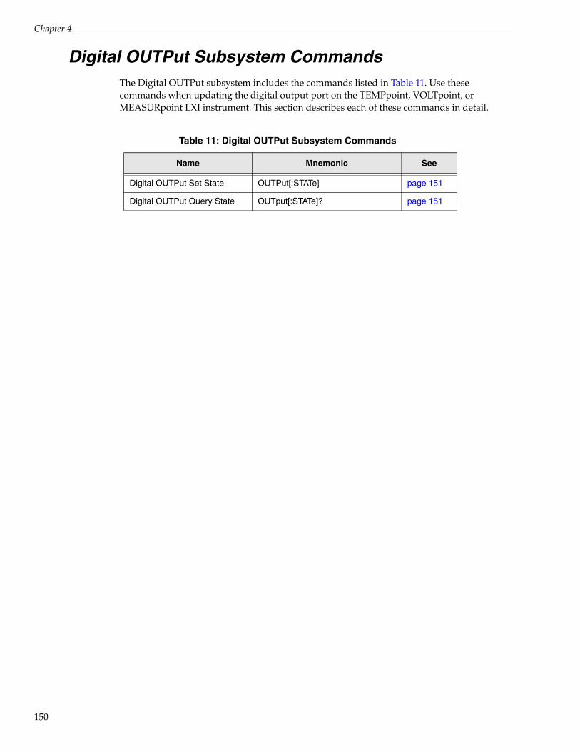
Chapter 4
150
Digital OUTPut Subsystem CommandsThe Digital OUTPut subsystem includes the commands listed in Table 11. Use these commands when updating the digital output port on the TEMPpoint, VOLTpoint, or MEASURpoint LXI instrument. This section describes each of these commands in detail.
Table 11: Digital OUTPut Subsystem Commands
Name Mnemonic See
Digital OUTPut Set State OUTPut[:STATe] page 151
Digital OUTPut Query State OUTput[:STATe]? page 151

SCPI Subsystem Commands
Digital OUTPut Query State
Digital OUTPut Set State
Description Returns the current state the digital output port on the instrument.
Syntax :OUTPut[:STATe]?
Parameters None
Response Data <outputport>
Name:
Data Format:
Description:
outputport
<0+NR1>
The weighted bit value of the digital output port, where the value of bit 0 (digital output line 0) corresponds to a decimal value of 1 (20) if the bit is set, and the value of bit 7 (digital output line 7) corresponds to a decimal value of 128 (27) if the bit is set.
Values for outputport range from 0 to 255.
Notes Refer to the 1999 SCPI Data Exchange Format, section 3.4.6.
Example >:OUTP:STAT?< 255
This response indicates that all the digital output lines of the digital output port are set to 1.
See Also OUTPut, described next
Description Sets the state the digital output port on the instrument.
Syntax :OUTPut[:STATe] <value>
Required Parameters
Name:
Data Format:
Description:
value
<0+NR1>
The weighted bit value of the digital output port, where the value of bit 0 (digital output line 0) corresponds to a decimal value of 1 (20) if the bit is set, and the value of bit 7 (digital output line 7) corresponds to a decimal value of 128 (27) if the bit is set.
Values for outputport range from 0 to 255.
Response Data None
Notes This is a password-protected command. To enable this command to function, use the SYSTem:PASSword[:CENable] command, described on page 83.
Refer to the 1999 SCPI Data Exchange Format, section 3.4.6, for more information on the data format.
151

Chapter 4
152
Example > :OUTP:STAT 129
This command sets digital output lines 0 and 7 (bits 0 and 7) to 1, and all the other digital output lines (bits) to 0.
See Also OUTPut?, described on page 151

5Programming Flowcharts
Using Password Protected Command . . . . . . . . . . . . . . . . . . . . . . . . . . . . . . . . . . . . . . . . . . 154
Analog Input - Single Value Operations . . . . . . . . . . . . . . . . . . . . . . . . . . . . . . . . . . . . . . . . . 155
Analog Input - Continuous Scan Operations . . . . . . . . . . . . . . . . . . . . . . . . . . . . . . . . . . . . . 156
Digital Input Operations . . . . . . . . . . . . . . . . . . . . . . . . . . . . . . . . . . . . . . . . . . . . . . . . . . . . . . 158
Digital Output Operations . . . . . . . . . . . . . . . . . . . . . . . . . . . . . . . . . . . . . . . . . . . . . . . . . . . . 159
153

Chapter 5
154
Using Password Protected Command
No
Enable the password-protected commands by supplying the current password using the
SYSTem:PASSword[:CENable] command, described on page 83.
YesAre password-
protected commands disabled?
Determine if password-protected commands are enabled or disabled using the
SYSTem:PASSword:CENable:STATe? command, described on page 85.
Configure the instrument and start the operation, as described on page 155 and
page 156.
No
Yes
Create new password?
If desired, set a new password using the SYSTem:PASSword:NEW command, described
on page 86.
YesDisablepassword-protected
commands?
To prevent some other SCPI client from stopping the scan and/or modifying the configuration, disable password-protected commands by
supplying the password using the SYSTem:PASSword:CDISable command,
described on page 81.

Programming Flowcharts
Analog Input - Single Value Operations
No
Configure analog input channels for thermocouple measurements and read temperature values from
these channels using the MEASure:TEMPerature:TCouple? query
described on page 134.
For channels that support programmable voltage ranges, configure the voltage range using the
CONFigure:VOLTage:RANGe command, described on page 111.
YesRead temperature from thermo-
couples?
Read voltage?
Yes
No
Configure the filter type using the CONFigure:FILTer command, described on
page 115.
YesRead resistance?
Configure analog input channels for resistance measurements and read resistance values from
these channels using the MEASure:RESistance? query, described on page 130.
No
Configure analog input channels for RTD measurements and read temperature values from
these channels using the MEASure:TEMPerature:RTD? query
described on page 134.
YesRead
temperature from RTDs?
Configure analog input channels for voltage measurements and read voltage values from these
channels using the MEASure:VOLTage? query, described on page 137.
155
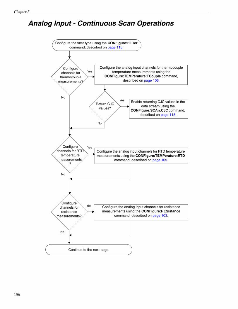
Chapter 5
156
Analog Input - Continuous Scan Operations
Continue to the next page.
YesConfigure the analog input channels for thermocouple
temperature measurements using the CONFigure:TEMPerature:TCouple command,
described on page 106.
YesReturn CJC
values?
Enable returning CJC values in the data stream using the
CONFigure:SCAn:CJC command, described on page 118.
No
Configure the filter type using the CONFigure:FILTer command, described on page 115.
No
Configure channels for
thermocouple measurements?
Yes
No
Configurechannels for RTD
temperaturemeasurements
?
Configure the analog input channels for RTD temperature measurements using the CONFigure:TEMPerature:RTD
command, described on page 109.
Configure the analog input channels for resistance measurements using the CONFigure:RESistance
command, described on page 103.
Yes
No
Configure channels for resistance
measurements?

Programming Flowcharts
Analog Input - Continuous Scan Operations (cont.)
Continued from the previous page.
Specify the channels to scan using the CONFigure:SCAn:LISt command, described on page 120.
Yes
No
Configure channels for
voltage measurements?
For channels that do not support programmable voltage ranges, configures the channels for voltage measurement
using the CONFigure:VOLTage command, described on page 109.
For channels that support programmable voltage ranges, configures the channel for voltage measurements and sets the voltage range using the CONFigure:VOLTage:RANGe
command, described on page 111.
Initiate the analog input operation using the INITiate command, described on page 140.
Retrieve the scan data from the circular buffer on the instrument using the FETCh? query,
described on page 145.
Specify the frequency at which to scan the analog input channels using the CONFigure:SCAn:RATe command,
described on page 123.
Return the indices of the oldest and most recent scan records using the STATus:SCAn? query, described on page 74.
Specify the trigger source using the CONFigure:TRIGger[:SOURce] command, described on
page 127.
157

Chapter 5
158
Digital Input Operations
Read the state of the digital input port using the INPut? query, described on page 149.

Programming Flowcharts
Digital Output Operations
Set the state of the digital output port using the OUTPut command, described on page 151.
159

Chapter 5
160

6Product Support
161

Chapter 6
162
Should you experience problems using SCPI to program a TEMPpoint, VOLTpoint, or MEASURpoint LXI instrument, follow these steps:
1. Read all the documentation provided for your product, including any “Read This First” information.
2. Install the latest software from the web at https://www.mccdaq.com/downloads/DTSoftware/MEASURpoint.
3. Check that you have installed your hardware devices properly. For information, refer to the documentation supplied with your devices.
4. Check that you have installed the device drivers for your hardware devices properly. For information, refer to the documentation supplied with your devices.
If you are still having problems, Data Translation’s Technical Support Department is available to provide technical assistance. To request technical support, go to our web site at www.mccdaq.com/Support.aspx.
When requesting technical support, be prepared to provide the following information:
• Your product serial number
• The hardware/software product you need help on
• The version of software that you are using
• Your contract number, if applicable
If you are located outside the USA, contact your local distributor; see our web site (www.mccdaq.com/International) for the name and telephone number of your nearest distributor.

AErrors
Error Codes . . . . . . . . . . . . . . . . . . . . . . . . . . . . . . . . . . . . . . . . . . . . . . . . . . . . . . . . . . . . . . . . . 164
Troubleshooting Errors . . . . . . . . . . . . . . . . . . . . . . . . . . . . . . . . . . . . . . . . . . . . . . . . . . . . . . . 166
163

Appendix A
164
Error CodesErrors are returned in your program as follows:
–110,"Command header error"
The number represents the error code and the string that follows represents the error description. Note that there is no space between the comma after error code and the quotation mark before the error description.
Table 12 lists the error codes that TEMPpoint, VOLTpoint, and MEASURpoint LXI instruments can return.
Table 12: SCPI Error Codes Returned by TEMPpoint, VOLTpoint, and MEASURpoint LXI Instruments
Error Code Error Message Description
0 No error Normal operation; no error occurred.
–100 Command error A command is missing a parameter, or the command contains too many parameters or too many dimensions.
–102 Syntax error An unrecognized command or data type was encountered; for example, a string was received when the instrument does not accept strings.
–104 Data type error A data element different than the one allowed was encountered; for example, numeric data was expected but string data was encountered.
–110 Command header error
The command header is invalid. See page 166 for information on troubleshooting this error.
–115 Unexpected number of parameters
The number of parameters received does not correspond to the number of parameters that were expected.
–120 Numeric data error The value of a parameter overflowed, has the wrong dimensions, or contains an invalid value.
–131 Invalid suffix The suffix does not follow the syntax described in IEEE 488.2, 7.7.3.2, or the suffix is inappropriate for this instrument.
–200 Execution error A <PROGRAM DATA> element following a header was evaluated by the instrument as outside of its legal input range or is otherwise inconsistent with the instrument’s capabilities.
A valid program message could not be executed properly due to some condition of the instrument.
–203 Command protected This is a password-protected command. Password protection is currently disabled. To use this command, you must enable password protection using the SYSTem:PASSword[:CENable] command, described on page 83.

Errors
–221 Settings conflict The specified channels of the instrument do not support the requested operation, or an invalid current password was entered. For example, this error is returned if you try to configure a thermocouple type for channels that do not support temperature, or try to configure a voltage range that is not supported by a channel.
–222 Data out of range A legal program data element was parsed but could not be executed because the interpreted value was outside the legal range for the instrument.
–284 Program currently running
Certain operations dealing with programs are illegal while the program is running; for example, you cannot configure/reconfigure an operation while a scan is in progress.
–350 Queue overflow The error queue is full; subsequent errors can not be added to the queue. Use the *CLS command, described on page 56, to clear the error queue as well as the Status Byte register
–410 Query interrupted The query did not complete. See page 167 for information on troubleshooting this error.
Table 12: SCPI Error Codes Returned by TEMPpoint, VOLTpoint, and MEASURpoint LXI Instruments (cont.)
Error Code Error Message Description
165

Appendix A
166
Troubleshooting ErrorsThis section describes how to troubleshoot the following frequently encountered errors:
• –110,"Command header error"
• –410,"Query interrupted"
Error –110 Command Header Error
This error indicates that the command you sent was not recognized by the instrument as a valid command name. Here are the most likely causes for receiving this error:
• A space is missing between the command and its parameter. At least one space (blank) must exist between the command and its parameter.
For example, this command will not be recognized and will return error –110:
:CONFigure:FILTerRAW wrong
This command, however, is correct and will not return an error:
:CONFigure:FILTer RAW right
• The command was specified with the improper short or long form.
For example, you can specify :CONF? but not :CON? for the CONFigure? command.
Refer to Chapter 3 starting on page 55 and Chapter 4 starting on page 65, for the correct command name.
• A space (blank) is inserted within the command name. Spaces are not permitted within the command name.
For example, this command is incorrect and will return error -110:
:SYST: ERR? Wrong
This command, however, is correct and will not return an error:
:SYST:ERR? Right
• The instrument did not return data. To return data from the instrument, the client must send a valid query to the instrument. For example, to return scan data, the client must issue the :FETCh? command once the scan has been initiated with the INITiate command.
• A client sent a valid query following an invalid command. This can occur when you send multiple commands or queries within one program message. When it detects an error in a program message, the instrument discards all further commands in the program message until the end of the string.
For example, consider the following program message:
*IDN?;*xyz;*STB?
The IDN? command executes properly, but the *xyz command generates error –110 and the rest of the program message is aborted; therefore, the *STB? command is ignored even though it is a valid query.

Errors
Error –410 Query Interrupted
Usually, this error occurs when a client sends a valid query to the instrument, and then sends another command or query to the instrument before reading the response from the first query.
For example, the following sequence of commands will cause error –410 because the response from :SYST:ERR? is not read before the *OPC command is sent to the instrument:
:SYST:ERR?*OPC?
167

Appendix A
168

BRegisters
Status Byte Register (STB) . . . . . . . . . . . . . . . . . . . . . . . . . . . . . . . . . . . . . . . . . . . . . . . . . . . . . 170
Standard Event Status Enable Register (ESE) . . . . . . . . . . . . . . . . . . . . . . . . . . . . . . . . . . . . 171
Standard Event Status Register (ESR) . . . . . . . . . . . . . . . . . . . . . . . . . . . . . . . . . . . . . . . . . . . 173
Operation Status Register . . . . . . . . . . . . . . . . . . . . . . . . . . . . . . . . . . . . . . . . . . . . . . . . . . . . . 174
169

Appendix B
170
Status Byte Register (STB)Table 13 lists the bits of the Status Byte register.
Table 13: Status Byte Register
Bit Name Description
0 Unused The value of this bit is always 0.
1 Unused The value of this bit is always 0.
2 Error / Event Queue Summary (EAV)
During an operation, the instrument stores error conditions as they occur in an Error / Event Queue.
If this bit is 1, the queue is not empty. To read the error message and empty the queue, use the SYST:ERR? command, described on page 78.
If this bit is 0, the Error / Event Queue is empty.
3 Questionable Register Summary TEMPpoint, VOLTpoint, and MEASURpoint LXI instruments do not implement the Questionable Data/Signal Status Register register. Therefore, the value of this bit is always 0.
4 Message Available (MAV) The Output Queue stores response messages until they are read.
If this bit is 1, an unread message exists. The instrument places Data Byte and END messages into the Output Queue in response to query commands. These messages are removed from the Output Queue as they are read by the controller. As long as the Output Queue contains an unread message, the value of the MAV bit is 1.
If this bit is 0, an unread message does not exist in the Output Queue.
5 Standard Event Status Bit (ESB) Summary
If this bit is 1, one or more bits in the Standard Event Status register, described on page 173, is set.
If this bit is 0, no bits are in Standard Event Status register are set.
6 Request Service TEMPpoint, VOLTpoint, and MEASURpoint LXI instruments do not implement the Request Service register. Therefore, the value of this bit is always 0.
7 Operation Status Register Summary
If this bit is 1, one or more bits in the device-dependent Operation Status register, described on page 174, is set.
If this bit is 0, no bits in the Operation Status register are set.

Registers
Standard Event Status Enable Register (ESE)Figure 13 shows the relationship between the Standard Event Status Enable and Standard Event Status registers.
Figure 13: Standard Event Status Enable (ESE) and Standard Event Status Registers (ESR)
Table 14 lists the bits of the Standard Event Status Enable (ESE) register.
RQC1
OPC0
QYE2
DDE3
E4
CME5
NU6
PON7
RQC1
OPC0
QYE2
DDE3
E4
CME5
NU6
PON7
&
&
&&
&
&
&
&
Lo
gic
al O
RStandard Event Status Register (*ESR?)
Standard Event Status Enable Register (*ESE and *ESE?)
Summary Message Event Summary Bit (ESB)(Bit 5 of the Status Byte Register)
171

Appendix B
172
Table 14: Standard Event Status Enable (ESE) Register
Bit Name Description
0 Operation Complete (OPC) This bit is always 1 on TEMPpoint, VOLTpoint, and MEASURpoint LXI instruments, since the instrument is always enabled to complete all pending overlapped commands.
Overlapped commands, such as calibration and measurement commands, are executed in parallel with subsequent commands that are sent to the instrument.
1 Request Control (RQC) This bit is always 0 on TEMPpoint, VOLTpoint, and MEASURpoint LXI instruments since the instrument is not configured to control GPIB operation.
2 Query Error (QYE) If this bit is set to 1, the Query Error bit (bit 2) of the Standard Event Status register is enabled.
If this bit is set to 0, the Query Error bit (bit 2) of the Standard Event Status register is disabled.
3 Device Dependent Error (DDE)
If this bit is set to 1, the Device Dependent Error bit (bit 3) of the Standard Event Status register is enabled.
If this bit is set to 0, the Device Dependent Error bit (bit 3) of the Standard Event Status register is disabled.
4 Execution Error (E) If this bit is set to 1, the Execution Error bit (bit 4) of the Standard Event Status register is enabled.
If this bit is set to 0, the Execution Error bit (bit 4) of the Standard Event Status register is disabled.
5 Command Error (CME) If this bit is set to 1, the Command Error bit (bit 5) of the Standard Event Status register is enabled.
If this bit is set to 0, the Command Error bit (bit 5) of the Standard Event Status register is disabled.
6 Not Used (NU) The value of this bit is always 0.
7 Power ON (PON) If this bit is set to 1, the Power ON bit (bit 7) of the Standard Event Status register is enabled.
If this bit is set to 0, the Power ON bit (bit 7) of the Standard Event Status register is disabled.

Registers
Standard Event Status Register (ESR)Table 15 lists the bits of the Standard Event Status register; see Figure 13 on page 171 for more information on how the Standard Event Status Enable register is used with this register.
Table 15: Standard Event Status (ESR) Register
Bit Name Description
0 Operation Complete (OPC) If this bit is set to 1, all pending operations are complete.
If this bit is set to 0, all pending operations have not been completed.
1 Request Control (RQC) Not supported. TEMPpoint, VOLTpoint, and MEASURpoint LXI instruments are not configured to control GPIB operation. Therefore, the value of this bit is always 0.
2 Query Error (QYE) If this bit is 1, a query error was detected indicating that an attempt was made to read data from the output queue when no data was present, or that data in the output queue was lost (an overflow condition occurred).
If this bit is 0, a query error did not occur.
3 Device Dependent Error (DDE)
If this bit is 1, a device-dependent error was detected, indicating that the A/Ds are not synchronized when the device is streaming data. When this error is detected, streaming is stopped and the A/Ds are synchronized.
If this bit is 0, the A/Ds are synchronized.
Refer to Appendix A on page 164 for a list of device-dependent errors that can be returned.
4 Execution Error (E) If this bit is 1, an Execution Error was detected indicating that a <PROGRAM DATA> element was outside the legal range or was inconsistent with the operation of the instrument, or that the instrument could not execute a valid command due to some internal condition.
If this bit is 0, an Execution Error did not occur.
5 Command Error (CME) If this bit is 1, a Command Error was detected indicating that the instrument received a command that did not follow proper syntax or was misspelled, or that the instrument received a command that was not implemented.
If this bit is 0, a Command Error did not occur.
6 Not Used (NU) The value of this bit is always 0.
7 Power ON (PON) If this bit is 1, power to the instrument was turned OFF and then ON since the last time the Power ON register was read.
If this bit is 0, power to the instrument was always ON between reads of the Power ON register.
173

Appendix B
174
Operation Status RegisterTable 16 lists the bits of the Operation Status register.
Table 16: Operation Status Register
Bit Name Description
0 Unused The value of this bit is always 0.
1 Unused The value of this bit is always 0.
2 Unused The value of this bit is always 0.
3 Unused The value of this bit is always 0.
4 Scan Status If this bit is 1 and bit 5 is 1, waiting for trigger. If this bit is 1 and bit 5 is 0, scanning is in progress.If this bit is 0 and bit 5 is 0, scanning is stopped.
5 Trigger Status If this bit is 1 and bit 4 is 1, waiting for trigger. If this bit is 0 and bit 4 is 1, scanning is in progress.If this bit is 0 and bit 4 is 0, scanning is stopped.
6 Unused The value of this bit is always 0.
7 Unused The value of this bit is always 0.
8 Unused The value of this bit is always 0.
9 Unused The value of this bit is always 0.
10 Unused The value of this bit is always 0.
11 Unused The value of this bit is always 0.
12 Unused The value of this bit is always 0.
13 Unused The value of this bit is always 0.
14 Unused The value of this bit is always 0.

CStructures
SCAN_RECORD Structure . . . . . . . . . . . . . . . . . . . . . . . . . . . . . . . . . . . . . . . . . . . . . . . . . . . . 176
175

Appendix C
176
SCAN_RECORD Structure
Description This structure stores the data from a single scan that is returned by the FETCh? query, described on page 145, in the circular buffer.
Structure struct {unsigned long tmStamp;unsigned long tmMillisec;unsigned long scanNumber;unsigned long numValues;float values[];
} SCAN_RECORD;
Members
Name:Description:
tmStamp The time stamp of the scan record, defined as the number of seconds that have elapsed since Coordinated Universal Time (UTC).The system time is synchronized with an SNTP server.
Name:Description:
tmMillisecThe millisecond after tmStamp at which the sample was acquired.
Name:Description:
scanNumberThe index of the scan record in the circular buffer.
Name:Description:
numValuesThe number of single-precision values that follow in the record.
Name:Description:
values[]A variable size array with a value from each channel that was specified in the channel list. If CJC measurements were enabled using CONFigure:SCAn:CJC, described on page 118, then the CJC values are paired with the corresponding channel’s measurement value.

DExamples
177

Appendix D
178
The MeasurementSCPI example illustrates how to use SCPI commands to program a TEMPpoint, VOLTpoint, or MEASURpoint instrument.
This example, written using Visual C# in Microsoft Visual Studio.NET 2005 and Visual C++ in Microsoft Visual Studio.NET 2003, enables three analog input channels (0, 1, and 2) for a scan, initiates the scan, and then fetches data from the circular buffer on the instrument. Note that for thermocouple measurements, the channels are configured for a J-type thermocouple. For RTD measurements, the channels are configured for a PT100 RTD type.
To open and run this example, do the following:
1. Start Microsoft Visual Studio .NET.
2. Click File, click Open, and then click Project.
3. If you are using Visual C# .NET, from the Windows Start menu, select the following: Programs -> Data Translation, Inc -> Measurement SCPI Support ->Examples -> C# ->MeasurementSCPI 2005. sln
If you are using Visual C++ .NET, from the Windows Start menu, select the following: Programs -> Data Translation, Inc -> Measurement SCPI Support ->Examples -> CPP ->MeasurementSCPIApp 2003. sln
4. From the main menu of Microsoft Visual Studio .NET, click Build, and then click Build Solution to build the project.
5. To run the example, click Debug from the main menu, and then click Start.The example program is now running.
6. Use the capabilities of the example program to see how it operates.
7. When you are finished using the example program, click Debug from the main menu, then click Stop Debugging.
8. View the user interface of the example program by clicking the appropriate [Design] tab on the main window.
9. View the source code for the example program by clicking the appropriate tab (such as example.cs) on the main window.

EUsing HyperTerminal to Send and
Receive SCPI Commands
179

Appendix E
180
You can use the standard Windows HyperTerminal application to send and receive SCPI commands. This may be useful when debugging your application
Note: SCPI commands return measurement data in binary format. Since HyperTerminal returns data in ASCII format, you cannot use HyperTerminal to directly interpret the measurement data from TEMPpoint, VOLTpoint, or MEASURpoint instruments. The Agilent Connection Expert tool or a network protocol analyzer, such as Wireshark, may be helpful in these instances.
To use the standard Windows HyperTerminal application to send and receive SCPI commands, do the following:
1. From the Start menu, click Programs ->Accessories - > Communications -> HyperTerminal.The HyperTerminal application opens and the following screen appears:
2. Enter a name for the connection, such as MyTerm, can click OK.The Connect To dialog appears:

Using HyperTerminal to Send and Receive SCPI Commands
3. In the Connect using field, select TCP/IP (Winsock). The other fields on the screen change accordingly.
4. Enter the IP address of the instrument (which you can locate using the Eureka Discovery Utility), and then enter 5025 as the port number.The screen should look as follows:
5. Click OK.
6. From the File menu, click Properties, and then click Settings.The following screen appears:
181

Appendix E
182
7. Click ASCII Setup...
8. Configure this dialog box so that the following options are checked: Send line ends with line feeds, Echo typed characters locally, and Wrap lines that exceed terminal width), and then click OK.The screen should look as follows:

Using HyperTerminal to Send and Receive SCPI Commands
9. Click OK to close the Property dialog box.The following screen appears:
10. From the Call menu, click Call.
183

Appendix E
184
11. Enter any of the documented SCPI commands or queries. The following screen shows an example:
12. When you are finished using the SCPI commands, select the Call menu, and then click Disconnect to terminate your connection with the instrument.

Index
Index
Symbols*CLS 56*ESE 56*ESE? 57*ESR? 57*IDN? 59*OPC 60*OPC? 60*RST 60*SRE 61*SRE? 62*STB? 62*TST? 61*WAI 63
AABORt Scan command 47, 143acquiring data
continuous scan operations 46single-value operations 43
analog inputcalibration 52channels 41conversion modes 43filtering 42input ranges 41
Auto-Calibrate command 52, 77Auto-IP 35
BBlock data types 26boards 40Boolean data types 26braces 21brackets 21
CChannel Configuration for Programmable Voltage
Ranges command 111Channel Configuration for Resistance command
103Channel Configuration for RTD Temperature
command 104
Channel Configuration for Thermocouples command 106
Channel Configuration for Voltage command 109Channel Configuration Query 113channel lists 28, 45channels, analog input 41character data types 23circular buffer 47, 48Clear Status command 56clients 48command header error 166command hierarchy 66common commands
*CLS 56*ESE 56*ESE? 57*ESR? 57*IDN? 59*OPC 60*OPC? 60*RST 60*SRE 61*SRE? 62*STB? 62*TST? 61*WAI 63
CONFigure subsystem commandsCONFigure:FILTer 42, 115, 155, 156CONFigure:FILTer? 43, 116CONFigure:RESistance 45, 103, 156CONFigure:SCAn:BUFfer 47CONFigure:SCAn:BUFfer? 117CONFigure:SCAn:CJC 45, 47, 118, 156CONFigure:SCAn:CJC? 119CONFigure:SCAn:LISt 45, 47, 120, 157CONFigure:SCAn:LISt? 122CONFigure:SCAn:RATe 46, 123, 157CONFigure:SCAn:RATe? 125CONFigure:TEMPerature:RTD 45, 156CONFigure:TEMPerature:TCouple 44, 104, 106,
156CONFigure:TRIGger[:SOURce] 46, 127, 157CONFigure:TRIGger[:SOURce]? 128CONFigure:VOLTage 44, 109, 157CONFigure:VOLTage:RANGe 42, 44, 111, 155,
157CONFigure? 42, 45, 113
185

Index
186
configuring channelscontinuous scan operations 44single-value operations 43
configuring filters 42continuous scan operations 44
aborting 46circular buffer for 47, 48configuring channels 44initiating 46retrieving data 48returning CJC values 45specifying a channel list 45specifying the scan rate 46specifying the trigger source 46storing data for 47
conversion modescontinuous analog input (scan mode) 44single-value analog input 43
DData Interchange Format (DIF) expressions 30data types 23
Block 26Boolean 26character 23NR1 24NR2 24NRf 25NRr 24string 23
DATE Query 77determining the LAN settings of an instrument 35determining the MEASURpoint configuration 40DHCP 35digital input operations 53
reading the digital input port in the analog data stream 45, 121
Digital INPut Query State command 149digital output operations 54Digital OUTPut Query State command 151Digital OUTPut Set State command 151Disable Password-Protected Commands command
81documentation 34
EEnable Password-Protected Commands command
83ERRor Count Query 79
ERRor Query 78errors 163, 164, 169, 170, 172, 173, 174, 175, 177,
179-110 166-410 167error codes 164troubleshooting 166
Event Status (ESR) register 173Event Status Enable (ESE) register 171Event Status Register Query 57examples 34, 178expression types 27
channel lists 28Data Interchange Format (DIF) 30instrument-specifier 31numeric 27numeric lists 29
FFETCh Data query 48, 145, 157FIFO 47, 48Filter Configuration command 115Filter Configuration Query 116filtering 42flowcharts
analog input - continuous scan 156, 157analog input - single values 155digital input 158digital output 159using password-protected commands 154
frequency, scan 46
Ggateway address 35
Hhelp 10hierarchy of commands 66HyperTerminal 179, 180
IIdentification query 59INITiate Scan command 46, 140, 157input channels 41input ranges 41INPut? query 53, 149, 158installation 34

Index
instrument configuration 40instrument-specifier expressions 31IP address 35
LLAN configuration 35LAN Configuration Reset command 80LAN IP Address Query 80LAN IP Subnet Mask Query 80
MMeasure Single Resistance Values command 130Measure Single RTD Temperature Values command
131Measure Single Thermocouple Temperature Values
command 134Measure Single Voltage Values command 137MEASure subsystem commands
MEASure:RESistance? 43, 130, 155MEASure:TEMPerature:RTD? 43, 131, 155MEASure:TEMPerature:TCouple? 43, 134, 155MEASure:VOLTage? 43, 137, 155
MeasurementSCPI example 178messages
program 19response 22
mnemonics 21
NNR1 data types 24NR2 data types 24NRf data types 25NRr data types 24numeric expression types 27numeric lists 29
OOperation Complete command 60Operation Complete Query 60Operation Condition Register Query 69Operation Event Register Enable command 70Operation Event Register Query 71operation modes
continuous analog input (scan mode) 44single-value analog input 43
Operation Status register 174Operation Status Register Enable Query 70
OUTPut subsystem commandsOUTPut 54, 151, 159OUTPut? 54, 151
Ppassword-protected commands 36port 5025 12Presetting registers command 71program messages 19
Qquery interrupted error 167Query Password Enable State command 85Questionable Condition Register Query 72Questionable Enable Register command 72Questionable Event Register Query 73Questionable Register Enable Query 73
Rrate, scan 46Read Status Byte query 62registers
Operation Status 174Standard Event Status (ESR) 173Standard Event Status Enable (ESE) 171Status Byte (STB) 170
related documents 10Reset command 60response messages 22
SScan Circular Buffer Query 117Scan CJC Configuration command 118Scan CJC Configuration Query 119Scan List Configuration command 120Scan List Configuration Query 122scan rate 46Scan Rate Configuration command 123Scan Rate Query 125Scan Status Query 74SCAN_RECORD structure 176SCPI clients 48SCPI data types 23SCPI expression types 27
channel lists 28Data Interchange Format (DIF) expressions 30instrument-specifier expressions 31
187
Index
188
numeric expressions 27numeric lists 29
SCPI support files 34SCPI Version Query 88Self-Test Query 61service and support procedure 162Service Request Enable command 61Service Request Enable Query command 62Set New Password command 86simultaneous single-value operations 43single-value analog input operations 43
configuring channels for resistance 43configuring channels for RTD measurements 43configuring channels for thermocouple
measurements 43configuring channels for voltage 43
sockets 12Standard Event Status (ESR) register 173Standard Event Status Enable (ESE) register 171Standard Event Status Enable Register command
56Standard Event Status Enable Register Query 57starting a scan 46static IP 35Status Byte (STB) register 170STATus subsystem commands
STATus:OPERation:CONDition? 69STATus:OPERation:ENABle 70STATus:OPERation:ENABle? 70STATus:OPERation:EVENt? 71STATus:PRESet 71STATus:QUEStionable:CONDition? 72STATus:QUEStionable:ENABle 72STATus:QUEStionable:ENABle? 73STATus:QUEStionable:EVENt? 73STATus:SCAn? 74, 157
stopping a scan 46string data types 23subnet mask 35Supported Board Model Name Query 90Supported Board Model Query 89Supported Board Number Query 88Supported Board Range Query 95Supported Board Voltage Range Query 91Supported Channels Query 92Supported Digital Input Lines Query 96Supported Digital Output Lines Query 96Supported Maximum Scan Rate Query 97Supported Minimum Scan Rate Query 98Supported RTD Channels Query 93Supported Thermocouple Channels Query 94
syntax conventions 11braces 21brackets 21common SCPI commands 20program messages 19response messages 22SCPI data types 23SCPI expression types 27SCPI subsystem commands 20short- and long-form mnemonics 21vertical bars 21
system configuration 40SYSTem subsystem commands
SYSTem:BOArd:MODel:NAMe? 40, 90SYSTem:BOArd:MODel? 40, 89SYSTem:BOArd:RANGe? 40, 91, 95SYSTem:BOArd? 40SYSTem:BOArd[:NUMber]? 88SYSTem:CALibrate 52, 77SYSTem:CHANnel:RTD? 41, 93SYSTem:CHANnel:TCouple? 41, 94SYSTem:CHANnel:VOLTage:RANGe? 42SYSTem:CHANnel? 41, 92SYSTem:COMMunicate:NETwork:IPADdress?
35, 80SYSTem:COMMunicate:NETwork:MASk? 35, 80SYSTem:DATE? 77SYSTem:DINput? 53, 96SYSTem:DOUTput? 54, 96SYSTem:ERRor:COUNt? 79SYSTem:ERRor? 78SYSTem:PASSword:CDISable 81, 154SYSTem:PASSword:CENable:STATe? 85, 154SYSTem:PASSword:NEW 86, 154SYSTem:PASSword[:CENable] 83, 154SYSTem:PRESet 35, 80SYSTem:SCAn:RATe:MAX? 46SYSTem:SCAn:RATe:MAXimum? 46, 97SYSTem:SCAn:RATe:MINimum? 46, 98SYSTem:TIME? 99SYSTem:TZONe 100SYSTem:TZONe? 100SYSTem:VERSion? 88
SYSTem:PASSword:CDISable 36, 81SYSTem:PASSword:CENable:STATe? 37, 85SYSTem:PASSword:NEW 37, 86SYSTem:PASSword[:CENable] 36, 83
TTCP port 5025 12
Index
technical support 10, 162TIME Query 99Time Zone Query 100Time Zone Set command 100trademark and copyright information 2trigger source 46Trigger Source Configuration command 127Trigger Source Query 128troubleshooting checklist 162troubleshooting errors 166troubleshooting procedure 162
Uusing HyperTerminal 179
Vvertical bars 21VISA 12voltage ranges 41VXI-11 clients 48
WWait-to-Continue command 63
189

Index
190