
Maine Electricity and Waste Inventory, Baseline and Model Inputs

Molten Salt Reactors (MSRs)For Electricity and Waste Destruction
Dr. Charles ForsbergOak Ridge National Laboratory
P.O. Box 2008; Oak Ridge, TN 37831-6180Tel: (865) 574-6783; E-mail: [email protected]
Presentation of Generation IV Nuclear Energy System Conceptto Office Of Nuclear Energy (DOE/NE-1)
U.S. Department of EnergyWashington, D.C.
June 7, 2002
The submitted manuscript has been authored by a contractor of the U.S. Government under contract DE-AC05-00OR22725. Accordingly, the U.S. Government retains a nonexclusive, royalty-free license to publish or reproduce the published form of this contribution, or allow others to do so, for U.S. Government purposes. File name: MSR.NCTWG.March.2000

Molten Salt Reactors (MSRs) Use a Molten Salt Coolant Containing Dissolved Fuel
• Thermal Neutron Reactor− Molten salt (71.6% 7LiF, 16% BeF2, 12% ThF4, 0.4% UF4)− Fuel and fission products dissolved in fluoride salt− Graphite moderator
• The Molten Salt Breeder Reactor (MSBR) was the backup for the LMFBR (1960s)− 1000-MW(e) conceptual design developed− Lower breeding ratio (1.033) compared with the LMFBR
• Fuel cycle (primarily at reactor site)− 233U–Thorium fuel cycle (breeder fuel cycle)− Other possible fuel cycles (actinide burner, once-through)− Batch or on-line removal of selected fission products− No fuel fabrication, qualification, or irradiation damage

Traditional Molten Salt Reactor
ORNL DWG 99C-6888R
HeatExchanger
Reactor
GraphiteModerator
SecondarySalt Pump
Off-gasSystem
PrimarySalt Pump
PurifiedSalt
ChemicalProcessing
Plant
Turbo-Generator
FreezePlug
Critically Safe, Passively Cooled Dump Tanks(Emergency Cooling and Shutdown)
Steam Generator
NaBF _NaFCoolant Salt
4
72LiF _Th
Fuel Salt_BeF F _UF4 4
566 Co
704 Co
454 Co
621 Co
538 Co

The Molten Salt Reactor Experiment Demonstrated the Concept
U-235 fuel operation• Critical June 1, 1965• Full power May 23, 1966• End operation Mar 26, 1968
U-233 fuel operation• Critical Oct 2, 1968• Full power Jan 28, 1969• Reactor shutdown Dec 12, 1969
Hours critical 17,655
Circulating fuel loop time hours 21,788
Equiv. full power hrs w/ 235U fuel 9,005
Equiv. full power hrs w/ 233U fuel 4,167
MSRE power = 8 MW thermal Core volume < 2 cubic meters
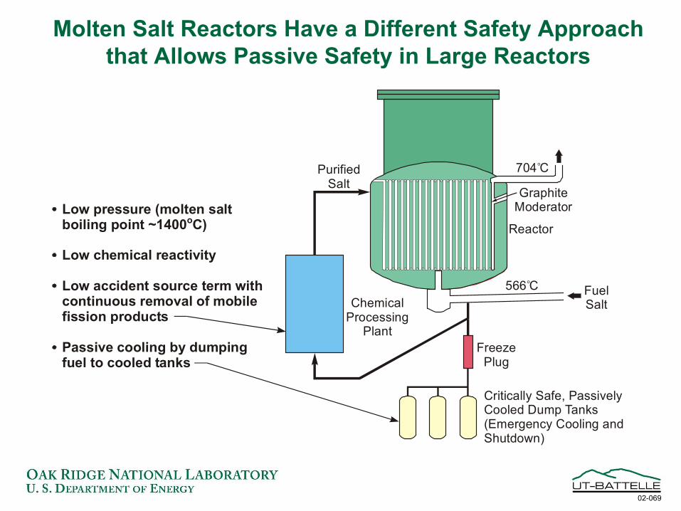
Molten Salt Reactors Have a Different Safety Approach that Allows Passive Safety in Large Reactors
02-069
Reactor
GraphiteModerator
PurifiedSalt
ChemicalProcessing
PlantFreeze
Plug
Critically Safe, PassivelyCooled Dump Tanks(Emergency Cooling andShutdown)
Low accident source term withcontinuous removal of mobilefission products
Low pressure (molten saltboiling point ~1400 C)o
Low chemical reactivity
Passive cooling by dumpingfuel to cooled tanks
FuelSalt
566 Co
704 Co

MSRs Have Advantages For Waste Burning:No Fuel Fabrication, Multiple Target/Fuel Recycle
Avoided, And Low Actinide Inventories
Thermal Reactors(with Pu recycle)
Thermal Reactors(with Pu recycle)
Fast Reactors(with Pu recycle)Fast Reactors
(with Pu recycle)
Pu, MA, ThI-129, Tc-99Pu, MA, ThI-129, Tc-99
Molten SaltBurner Reactor
MiningMining
EnrichmentEnrichment
Final Form Product DisposalFinal Form Product Disposal
Enriched Uranium Depleted Uranium
Pu
Fuel Cycle Advocated in Kurchatov Study
RussiaEC (CEA-France)Edf (France)KoreaCzech RepublicU.S. (Academic)
Ongoing Molten-Salt Transmutation Programs
02-070

Extended Molten Salt Reactor Family
Molten Salt Fueled Molten Salt Cooled
• Aircraft Nuclear Propulsion Program (1950s)
• Molten Salt Breeder Reactor Program (1960s)
• Molten salt burner (Russia, France, etc.)
• Molten salt space reactor (ORNL and MSFC)
• Advanced High-Temperature Reactor
• Special reactors• Fusion reactors (Tritium
production with 6Li)− Inertial− Magnetic

Fluoride Molten Salt R&D Activities in the United States
• Basic Energy Sciences (ORNL)• Fuel processing (ORNL, ANL, INEEL)
− Ongoing fluoride salt processing programs at ORNL• Materials (ORNL)
− Hastelloy N (1970s)− Chemical redox control (1980s)− High-temperature test loops (current)
• Space reactors (ORNL)• Advanced High-Temperature Reactor (ORNL, SNL)• Actinide burning (University of California)• Fusion (University of California, LLNL, etc.)• Special reactors

Areas for R&D
• Major areas for R&D− Actinide solubility limits in multi-component systems
• Higher actinide concentrations in burner MSRs• Alternative fluoride salts (Be or Li free)
− Fission-gas control (tritium, etc.)− Waste processing and waste form
• Other areas− Accident evaluations− Higher-temperature materials− Nonproliferation analysis− Alternative power cycles (gas turbines, etc.)− New separations technologies− Understanding graphite limitations

Conclusions
• Molten salt test reactor built in the 1960s• GIF interest in molten-salt-fueled reactors
− Efficient fuel resources− Waste burners (Primary interest)
• Growing programs in Europe and Russia• Base technology used by multiple programs• R&D issues reasonably well understood

Backup Information

Molten Salt Characteristics
• Molten fluoride salts preferred− Low nuclear cross section− Chemical stability
• Choice of salt depends upon mission− Breeder (low absorption cross section: Li, Be
fluorides− Waste burner (high solubility: all actinides)− Hydrogen production (low tritium production: Zr,
Na fluorides)• Extensive industrial experience
− Aluminum metal made using molten fluoride salt

ORNL Molten Salt Loop Evaluates High-Temperature Material/Salt Performance
Hastelloy N loop material– Compatible with salts– Stable to 1255°K
Maximum temperature 1073°K
Temperature differential: 50 to 100°K
Molten salt flow due to differences in densities with temperature
~2 liters total volume

Thermal Convection Loop Establishes Compatibility for the
Most Realistic Conditions
Insert line drawing A and Picture B
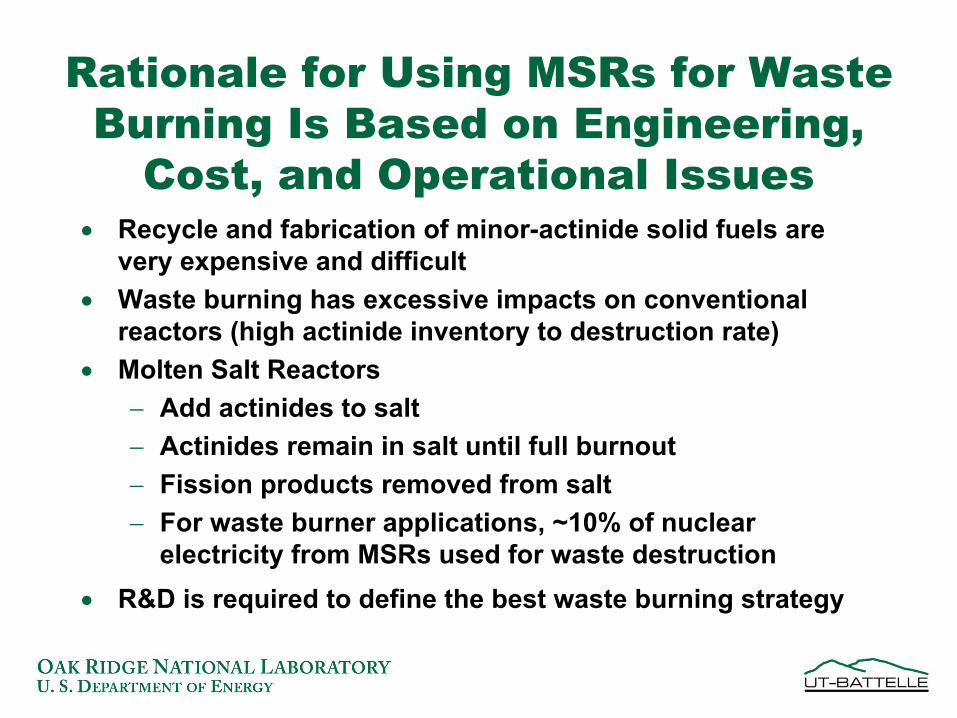
Rationale for Using MSRs for Waste Burning Is Based on Engineering,
Cost, and Operational Issues• Recycle and fabrication of minor-actinide solid fuels are
very expensive and difficult• Waste burning has excessive impacts on conventional
reactors (high actinide inventory to destruction rate)• Molten Salt Reactors
− Add actinides to salt− Actinides remain in salt until full burnout − Fission products removed from salt− For waste burner applications, ~10% of nuclear
electricity from MSRs used for waste destruction• R&D is required to define the best waste burning strategy

MSR Fuel Cycles
• Thermal neutron (233U/Th) breeder reactor• Denatured low-conversion breeder reactor• Denatured once-through fuel cycle • Actinide burning (intrinsic to concept)

The Proliferation-Resistant Characteristics of the MSR Are
Different Than Those of Other Systems
• Low total fissile inventory• With added 238U, 233U made non-weapons-
usable• Very poor plutonium isotopics (primarily
242Pu)

Advanced High-Temperature Reactor (AHTR):(Solid Fuel and Salt Coolant for Hydrogen Production)
• Goals− Hydrogen production− Efficient electricity production
• Requirements for hydrogen production define reactor design− Low pressure− Heat delivered at a high, almost-constant temperature− No tritium− Isolation of reactor from chemical facility
• AHTR design characteristics− Solid coated-particle fuel (similar to gas-cooled reactors)− Molten salt coolant (Na/Zr fluoride, etc.)

The AHTR Uses a Multi-Reheat Brayton Cycle for High-Efficiency Electricity Production
01-038
ControlRods Hot Molten Salt
Cooling Water
Generator
Recuperator
GasCompressor
Hot Air Out
AirInlet
Fuel(Similar toMHTGR)
ReactorVesselGuardVessel
ReactorElectric Power Cycle
Multi-Reheat Helium Brayton CyclePassive DecayHeat Removal

AHTR Liquid Cooling Allows All the Heat to Be Delivered at Near Reactor Exit Temperatures(Match Thermochemical Hydrogen Production Requirements)
01-031
PWR
LMFBR
AGR
HTGR-GT
AHTR
Hydrogen Production
AHTR
0
200
400
600
800
1000
InletDelivered Heat
Outlet
LiquidGas
Tem
pera
ture
(°C
)
(General Atomics)
(Hinkley Point B)
(Super Phenix)
(Point Beach)
925°C
675°C
491°C
395°C
310°C
299°C
545°C
319°C
665°C
750°C
850°C
1000°C


![Electricity generation potential from solid waste in three … · 2018-12-20 · Electricity generation potential from solid waste in three Colombian municipalities [112] TecnoLógicas,](https://static.fdocuments.us/doc/165x107/5f0aec537e708231d42e0134/electricity-generation-potential-from-solid-waste-in-three-2018-12-20-electricity.jpg)