![L T];1E PRODUCTION AND TRANSPORT OF …/67531/metadc680145/m2/1/high... · Split-Pole Spectrograph future (Tl) and present ... The quadrupole doublets are in a YX-YX- ... the 140](https://static.fdocuments.us/doc/165x107/5aa55fa37f8b9a7c1a8d437f/l-t1e-production-and-transport-of-67531metadc680145m21highsplit-pole.jpg)
FOR - Digital Library/67531/metadc685405/m2/1/high... · MeV 140 and 15 MeV %e. ... Split-Pole...
5
THE FIRST PRODUCTION AND TRANSPORT OF RADIOACTIVE "F AT ATLAS FOR RESEARCH c -., * +cEpFc SEP 0 3 1996 OSTI B. Harss, J.C. Berger, J. Greene, C.L. Jiang, J. Nolen, R.C. Pardo, M.Pault, Argonne National Laboratory, Argonne, IL, USA 60439 CX BS ' L K.E. Rehm, J.P. Schiffer, RE.Segeltt, T.F.Wangtw 'Hebrew University, Jerusalem, Israel 9 1904 tt Northwestern University, Evanston, Illinois USA ttt Lawrence Livermore National Laboratory, Livermore, California USA Abstract A secondary beam of radioactive I7F was produced at the ATLAS accelerator and delivered to an experimental target station with an intensity of at least 2.10' particles per second for use in the research program. The beam was produced through the p( 0, F)n inverse reaction by bombarding a hydrogen gas target with 250 particle nA of 83 MeV 170 from the ATLAS superconducting linac. The gas target was maintained at a pressure of 300 Torr arid a temperature of 257K. Beam quality was dominated by multiple scattering in the gas cell windows and by the reaction kinematics and beamline acceptance for energy spread. 17 17 Introduction Radioactive beams have many applications in modem nuclear physics and astrophysics. This potential has caused several accelerator laboratories around the world to develop techniques to produce radioactive beams with useful intensities and controllable beam properties. The effort to develop a "F beam at the superconducting, linac ATLAS [ 11 is primarily aimed at measurements of interest in astrophysics, but is also a demonstration of a technique to produce on-line, short half-life radioactive beams, and deliver these to a secondary tpget. The physics oal of the experiment was to measure the cross-section for F(~,~)'~O in the 3 to 4. MeV region in the center of mass system. For this measurement, the inverse reaction p( F, 0)a is appealing, because a target of I7F (T, = 65s) is not possible. For such a short half-life, the batch transfer process, as >as been used for radioactive beams '*F (T% = 109m) [2,3], is also impractical. Therefore, a primary proton target was used to transform a fraction of an 170 beam to a I7F beam. A bending magnet selected the fluorine particles in charge state 9+, thereby filtering out most of the 0 isobar nuclei. Finally, the I7F beam was delivered over a distance of 12 m to a secondary CH2 target. The desired 17F beam energy for the 3.63 MeV resonance in inverse kinematics is 62 to 63 MeV, producinp a proximately 45 MeV 140 and 15 MeV %e. Since p( F, O)a is forward peaked in the laboratory system, the ATLAS spectrograph was used as a powerfbl tool to separate the I4O nuclei from the background of scattered particles. IF 17 14 17 rJ If Severe challenges had to be overcome in order to carry Build a sufficiently robust proton production target Transport the "F beam of huge energy spread and divergence with maximum efficiency to the target Understand and handle beam impurities 0 Identify clearly I4O in the spectrograph in the presence of different backgrounds. out a successful measurement with this technique: Experimental Configuration The physical layout showing the relationship of the 17F production target, the connecting beamline to the secondary target and the ATLAS spectrograph is shown in Fig. 1. Primary Beam 22 Deg. Switching Magnet Split-Pole Spectrograph Fig. I. Floor plan of the spectrograph area showing the positions of the primary gas target and the secondary target in front of the ATLAS spectrograph. Design of the I7F Production Target The I7F production target must be capable of sustaining an I7O beam current of as much as one particle FA and have an effective thickness of at least 250 pg/cm2, in order to obtain
Transcript of FOR - Digital Library/67531/metadc685405/m2/1/high... · MeV 140 and 15 MeV %e. ... Split-Pole...

THE FIRST PRODUCTION AND TRANSPORT OF RADIOACTIVE "F AT ATLAS FOR RESEARCH
c -., * +cEpFc
SEP 0 3 1996
O S T I
B. Harss, J.C. Berger, J. Greene, C.L. Jiang, J. Nolen, R.C. Pardo, M.Pault,
Argonne National Laboratory, Argonne, IL, USA 60439
C X BS'L K.E. Rehm, J.P. Schiffer, RE.Segeltt, T.F.Wangtw
'Hebrew University, Jerusalem, Israel 9 1904 tt Northwestern University, Evanston, Illinois USA
ttt Lawrence Livermore National Laboratory, Livermore, California USA
Abstract
A secondary beam of radioactive I7F was produced at the ATLAS accelerator and delivered to an experimental target station with an intensity of at least 2.10' particles per second for use in the research program. The beam was produced through the p( 0, F)n inverse reaction by bombarding a hydrogen gas target with 250 particle nA of 83 MeV 170 from the ATLAS superconducting linac. The gas target was maintained at a pressure of 300 Torr arid a temperature of 257K. Beam quality was dominated by multiple scattering in the gas cell windows and by the reaction kinematics and beamline acceptance for energy spread.
17 17
Introduction
Radioactive beams have many applications in modem nuclear physics and astrophysics. This potential has caused several accelerator laboratories around the world to develop techniques to produce radioactive beams with useful intensities and controllable beam properties. The effort to develop a "F beam at the superconducting, linac ATLAS [ 11 is primarily aimed at measurements of interest in astrophysics, but is also a demonstration of a technique to produce on-line, short half-life radioactive beams, and deliver these to a secondary tpget.
The physics oal of the experiment was to measure the cross-section for F ( ~ , ~ ) ' ~ O in the 3 to 4. MeV region in the center of mass system. For this measurement, the inverse reaction p( F, 0)a is appealing, because a target of I7F (T, = 65s) is not possible. For such a short half-life, the batch transfer process, as >as been used for radioactive beams '*F (T% = 109m) [2,3], is also impractical. Therefore, a primary proton target was used to transform a fraction of an 170 beam to a I7F beam. A bending magnet selected the fluorine particles in charge state 9+, thereby filtering out most of the 0 isobar nuclei. Finally, the I7F beam was delivered over a
distance of 12 m to a secondary CH2 target. The desired 17F beam energy for the 3.63 MeV resonance in inverse kinematics is 62 to 63 MeV, producinp a proximately 45 MeV 140 and 15 MeV %e. Since p( F, O)a is forward peaked in the laboratory system, the ATLAS spectrograph was used as a powerfbl tool to separate the I4O nuclei from the background of scattered particles.
I F
17 14
17
rJ I f
Severe challenges had to be overcome in order to carry
Build a sufficiently robust proton production target Transport the "F beam of huge energy spread and divergence with maximum efficiency to the target Understand and handle beam impurities
0 Identify clearly I4O in the spectrograph in the presence of different backgrounds.
out a successful measurement with this technique:
Experimental Configuration
The physical layout showing the relationship of the 17F production target, the connecting beamline to the secondary target and the ATLAS spectrograph is shown in Fig. 1.
Primary Beam
22 Deg. Switching Magnet
Split-Pole Spectrograph
Fig. I. Floor plan of the spectrograph area showing the positions of the primary gas target and the secondary target in front of the ATLAS spectrograph.
Design of the I7F Production Target
The I7F production target must be capable of sustaining an I7O beam current of as much as one particle FA and have an effective thickness of at least 250 pg/cm2, in order to obtain

DISCLAIMER
Portions of this document may be illegible in electronic image products. Images are produced from the best available original document.

DISCLAIMER
This report was prepared as an account of work sponsored by an agency of the United States Government. Neither the United States Government nor any agency thereof, nor any of their employees, makes any warranty, express or implied, or assumes any legal liiability or responsibility for the accuracy, completeness, or use- fulness of any infonnation, apparatus, product, or process disclosed, or represents that its use would not infringe privately owned rights. Reference herein to any spe- cific commercial product, process, or service by trade name, trademark, manufac- turer, or otherwise does not necessarily constitute or imply its endorsement, ream- mendation, or favoring by the United States Government or any agency thereof. The views and opinions of authors expressed herein do not necessarily state or reflect those of the United States Government or any agency thereof.
more than lo5 particles per second on the secondary target given the I7F production cross-section [4] in the order of 10 to 100 mb and a transport efficiency of about one percent.
Experience indicates that foil (CHd targets cannot take the necessary high beam current, even in rapid rotation. Therefore, a gas target with an effective Nength of 7.5cm and thin HAVAR [5,6] windows was chosen Piee Fig. 2.1. To keep the temperature of both the windows and the hydrogen gas low, the chamber has double walls to accalmodate a constantly flowing cooling liquid in the outer cylider. Four support pipes supply cooling fluid and H, gas.
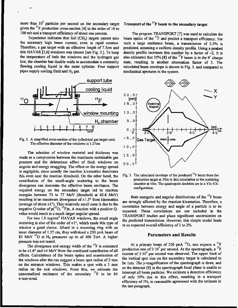
Transport of the "F beam to the secondary target
The program TRANSPORT [7] was used to calculate the beam optics of the "F and predict a transport efficiency. For such a large emittance beam, a transmission of 3.5% is predicted, assuming a uniform density profile. Using a peaked density profile increases this number by a factor of -2. It is also estimated that 35% [SI of the I7F beam is in the 9' charge state, resulting in another attenuation factor of 3. The calculated beam envelope is shown in Fig. 3. and compared to mechanical apertures in the system.
support tube
1 1 1 1 1 1
H, chamber 5 + 0.- 2 3 4 5 6 7 8 Q 10 : 'W
Fig. 2. A simplified cross-section of the cylindrical gas target used. The effective diameter of the windows is 1.27cm
I O 0-
15.0-
. - The selection of window material and thickness was
made as a compromise between the maxirnum sustainable gas pressure and the deteterious effect of thick windows on angular and energy straggling. The effect on the energy spread is negligible, since usually the reaction kinematics dominates this even near the reaction threshold. On the other hand, the contribution of the small-angle scattering to the beam divergence can dominate the effective beam emittance. The required energy on the secondary target led to reaction energies between 73 to 77 MeV (threshold at 63.8 MeV) resulting in'an maximum divergence of *I So from kinematics (average of about *lo). This relatively smdl cone is due to the negative Q-value of p(170, 17F)n. A reaction with a positive Q- value would result in a much larger angular spread.
For two 1.9 mg/cm2 HAVAR windows, the small angle scattering is also of the order of *lo, which made this type of window a good choice. Glued in a moulniing ring with an inner diameter of 1.27 cm, they withstood a 250 pnA beam of 83 MeV "0 at H, pressures up to of 460 Torr. A higher pressure was not tested.
The divergence and energy width of' the 17F is estimated to be ~k1.6" and *4 MeV from the combined contribution of all
Fig. 3. The calculated envelope of the produced I7F beam from the production target at 30m in this calculation to the scattering chamber at 43m. The quadrupole doublets are in a YX-YX- configuration.
Parameters and Results
At a primary beam of 250 pnA I7O, one expects a I7F production rate Of 2*107 per second. At the spectrograph, a "F
effects. Calculations of &e beam optics and examination of current of 1*105 per second was observed* The upper limit Of
be lcm. m e y-magnification ofthe S P e ~ O ~ P h is three, and the windows after the Iun suggest a beam spot radius of mm
radius on the exit windows. From this, we estimate the
n.mm-mrad.
the vertical spot size on the secondary target is calculated to
so the detector [9] in the spectrograph focal plane is unable to
of only 50% due to this effect, resulting in a transport efficiency of 1%, in reasonable agreement with the estimate in
on the entrance windows. This makes a spot with a 3 mm
umoma]ized emittance of the seconclary 17 to be 84 intercept all beam particles. We estimate a detection efficiency
Both energetic and angular distributions of the I7F beam are strongly affected by the reaction kinematics. Therefore, a correlation between energy and angle of a particle is to be expected. These correlations are not included in the TRANSPORT studies and place significant uncertainties OR the predicted transmission. However, this simple model leads to an expected overall efficiency of 1 to 2%.
the last paragraph.

The ratio of "F particles to other nuclei detected in the focal plane of the spectrograph in the experiment was better than 3:1, in a measurement taken at 0" and therefore with a much weaker primary 170 beam of only 175ppA on the gas target [See Fig. 4).
.- 5 E m c * -
"F tit 63 MeV iecondary Radioadwe Beam :omponents at Spectrograph
W M < 1MeV ...=I "0- at 28 MeV "0" at 38 M ~ V Energy "0" at 50 blev
Fig. 4. The energy spectrum of the secondary beam in the ATLAS spectrograph at Oo without gates.
The goal of the experiment was to detect 140 nuclei from F@,a)I4O in inverse kinematics. To provide easy
discrimination between ''0 nuclei and background, the a particle was detected in coincidence in a silicon detector. WhiIe the spectrograph covered 2O to IO" on the left side of the beam, the alpha detector measured aparticles on the right side between 6" and 20°. In the coincidence spectrum, the I4O particles are the most prominent group [see Fig. 51. The "F and "0 particles scattered in the spectrograph are only in random coincidence with uncorrelated particles in the silicon detector.
17
a-Coincidence Spectrum 9
.
1 . . . . . . . . . :. :. .l . . \. M/Q
By slightly changing the field of the 22" switching magnet, a certain energy control of the secondary beam was available without retuning the accelerator. Due to the large energy spread in the I7F particles, the c m n t of the secondary beam did not change more than 50% when swept over a 2 MeV energy region.
Summary and outlook
This fust experiment with a radioactive "F-beam shows that a gas target can be used to produce a radioactive beam from a stable beam in flight. However, it is difficult to transport the secondary beam, and the accessible energy range is restricted by the cross-section and the reaction kinematics. Nevertheless, the technique works well, producing on the order of a few lo5 particles per second. With this radioactive beam, it is already possible to measure an astrophysically significant nuclear reaction cross section.
To gain a larger range of accessible energies, to uncouple the production reaction energy from the energy of the secondary beam, and to reduce the energy spread of the secondary beam, the production target has to be moved in front of active elements of the accelerator system. A strong focusing element, directly after the gas target also improves the overall transport efficiency. However, the acceptance of the rest of the beam transport system limits this effect.
Testing different production target locations and the refinement of the gas target itself are the next steps in the development of this in-beam production of radioactive beams at ATLAS..
Acknowledgments
This work was supported by the US D.O.E., Nuclear Science Division, under contract No. W-3 1-109-ENG-38.
References
[l] L.M. Bollinger, et al., Nucl. Inst. and Meth. A328, (1993) 21 1. [2] R.Coszach, et al., Phys. Lett. EEi, (1995) 184. [3] A.D.Roberts, et al., Nucl. Inst. and Meth., MQ3 (1995) 523. [4] J.K.Blair, Phys. Rev.€& (l), (1973) 120. [5] L.S. Skaggs, et al., Proc. of the World Conf. of the Internatzional Nucl. Target Development Society, Bosten, MA, USA (1 979) 249. [6] J.D. Carlson, Nucl. Inst. and Meth. JU (1973) 541. f7] K.L. Brown, Advances Particle Phys. 1, (1967) 71. [8] K.Shima, et al., Atomic Data and Nuc. Data Tables, 24 (3) (1986) 358. [9] K.E.Rehm, F.L.H. Wolfs, Nucl. Inst. and Meth., A , Z i (1988) 262.
Fig. 5. The spectrum of nuclei in the spectroguaph in coincidence with a-particles in the silicon detector. The values of Z and WQ have been liniarized.