FN-1042-ULADA NAC Power Extender Installation Guide
16
Rev. 101413 FN-1042-ULADA NAC Power Extender Installation Guide (See Application Guide for additional information) Altronix Corp. 140 58th St. Brooklyn, NY
Transcript of FN-1042-ULADA NAC Power Extender Installation Guide

Rev. 101413
FN-1042-ULADANAC Power Extender
Installation Guide(See Application Guide for additional information)
Altronix Corp.140 58th St. Brooklyn, NY
- 2 - FN-1042-ULADA
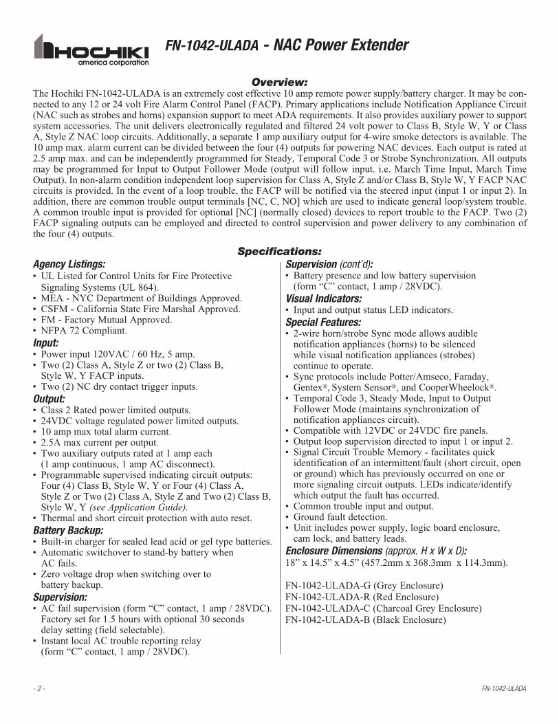
Agency Listings:• ULListedforControlUnitsforFireProtective SignalingSystems(UL864).• MEA-NYCDepartmentofBuildingsApproved.• CSFM-CaliforniaStateFireMarshalApproved.• FM-FactoryMutualApproved.• NFPA72Compliant.Input:• Powerinput120VAC/60Hz,5amp.• Two(2)ClassA,StyleZortwo(2)ClassB, StyleW,YFACPinputs.• Two(2)NCdrycontacttriggerinputs.Output:• Class2Ratedpowerlimitedoutputs.• 24VDCvoltageregulatedpowerlimitedoutputs.• 10ampmaxtotalalarmcurrent.• 2.5Amaxcurrentperoutput.• Twoauxiliaryoutputsratedat1ampeach (1ampcontinuous,1ampACdisconnect).• Programmablesupervisedindicatingcircuitoutputs: Four(4)ClassB,StyleW,YorFour(4)ClassA, StyleZorTwo(2)ClassA,StyleZandTwo(2)ClassB, StyleW,Y(see Application Guide).•Thermalandshortcircuitprotectionwithautoreset.Battery Backup:•Built-inchargerforsealedleadacidorgeltypebatteries.•Automaticswitchovertostand-bybatterywhen ACfails.• Zerovoltagedropwhenswitchingoverto batterybackup.Supervision: •ACfailsupervision(form“C”contact,1amp/28VDC). Factorysetfor1.5hourswithoptional30seconds delaysetting(fieldselectable).• InstantlocalACtroublereportingrelay (form“C”contact,1amp/28VDC).
Supervision (cont’d):•Batterypresenceandlowbatterysupervision (form“C”contact,1amp/28VDC).Visual Indicators:•InputandoutputstatusLEDindicators.Special Features: • 2-wirehorn/strobeSyncmodeallowsaudible notificationappliances(horns)tobesilenced whilevisualnotificationappliances(strobes) continuetooperate.• SyncprotocolsincludePotter/Amseco,Faraday, Gentex®,SystemSensor®,andCooperWheelock®.• TemporalCode3,SteadyMode,InputtoOutput FollowerMode(maintainssynchronizationof notificationappliancescircuit).• Compatiblewith12VDCor24VDCfirepanels.•Outputloopsupervisiondirectedtoinput1orinput2.•SignalCircuitTroubleMemory-facilitatesquick identificationofanintermittent/fault(shortcircuit,openorground)whichhaspreviouslyoccurredononeormoresignalingcircuitoutputs.LEDsindicate/identifywhichoutputthefaulthasoccurred.• Commontroubleinputandoutput.• Groundfaultdetection.•Unitincludespowersupply,logicboardenclosure, camlock,andbatteryleads.Enclosure Dimensions (approx. H x W x D):18”x14.5”x4.5”(457.2mmx368.3mmx114.3mm).
FN-1042-ULADA-G(GreyEnclosure)FN-1042-ULADA-R(RedEnclosure)FN-1042-ULADA-C(CharcoalGreyEnclosure)FN-1042-ULADA-B(BlackEnclosure)
Overview:TheHochikiFN-1042-ULADAisanextremelycosteffective10ampremotepowersupply/batterycharger.Itmaybecon-nectedtoany12or24voltFireAlarmControlPanel(FACP).PrimaryapplicationsincludeNotificationApplianceCircuit(NACsuchasstrobesandhorns)expansionsupporttomeetADArequirements.Italsoprovidesauxiliarypowertosupportsystemaccessories.Theunitdeliverselectronicallyregulatedandfiltered24voltpowertoClassB,StyleW,YorClassA,StyleZNACloopcircuits.Additionally,aseparate1ampauxiliaryoutputfor4-wiresmokedetectorsisavailable.The10ampmax.alarmcurrentcanbedividedbetweenthefour(4)outputsforpoweringNACdevices.Eachoutputisratedat2.5ampmax.andcanbeindependentlyprogrammedforSteady,TemporalCode3orStrobeSynchronization.AlloutputsmaybeprogrammedforInput toOutputFollowerMode(outputwill followinput. i.e.MarchTimeInput,MarchTimeOutput).Innon-alarmconditionindependentloopsupervisionforClassA,StyleZand/orClassB,StyleW,YFACPNACcircuitsisprovided.Intheeventofalooptrouble,theFACPwillbenotifiedviathesteeredinput(input1orinput2).Inaddition,therearecommontroubleoutputterminals[NC,C,NO]whichareusedtoindicategeneralloop/systemtrouble.Acommontroubleinputisprovidedforoptional[NC](normallyclosed)devicestoreporttroubletotheFACP.Two(2)FACPsignalingoutputscanbeemployedanddirectedtocontrolsupervisionandpowerdeliverytoanycombinationofthefour(4)outputs.
Specifications:
FN-1042-ULADA - NAC Power Extender
FN-1042-ULADA - 3 -
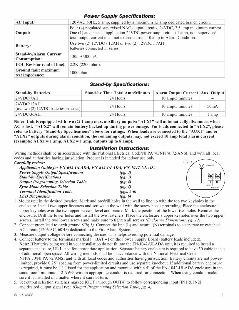
Power Supply Specifications:AC Input: 120VAC60Hz,5amp,suppliedbyamaximum15ampdedicatedbranchcircuit.
Output:Four(4)regulatedsupervisedNACoutputcircuits,24VDC,2.5ampmaximumcurrent.One(1)aux.specialapplication24VDCpoweroutputcircuit1amp,non-supervisedtotaloutputcurrentmustnotexceedcurrent10ampinAlarmCondition.
Battery:Usetwo(2)12VDC/12AHortwo(2)12VDC/7AHbatteriesconnectedinseries.
Stand-by/Alarm Current Consumption:
130mA/300mA
EOL Resistor (end of line): 2.2K(2200ohm).Ground fault maximumtest impedance:
1000ohm.
Stand-by Specifications:
Stand-by Batteries Stand-by Time Total Amp/Minutes Alarm Output Current Aux. Output24VDC/7AH 24Hours 10amp/5minutes ---24VDC/12AH(usetwo(2)12VDCbatteriesinseries) 24Hours 10amp/5minutes 50mA
24VDC/36AH 24Hours 10amp/5minutes 1amp
Note: Unit is equipped with two (2) 1 amp max. auxiliary outputs: “AUX1” will automatically disconnect whenAC is lost. “AUX2” will remain battery backed up during power outage. For loads connected to “AUX2”, please refer to battery “Stand-by Specifications” above for ratings. When loads are connected to the “AUX1” and or “AUX2” outputs during alarm condition, the remaining outputs may, not exceed 10 amp total alarm current. (example: AUX1 = 1 amp, AUX2 = 1 amp, outputs up to 8 amp).
Installation Instructions:WiringmethodsshallbeinaccordancewiththeNationalElectricalCode/NFPA70/NFPA72/ANSI,andwithalllocalcodesandauthoritieshavingjurisdiction.Productisintendedforindooruseonly.Carefully review: Application Guide for FN-642-ULADA, FN-842-ULADA, FN-1042-ULADA Power Supply Output Specifications (pg. 3) Stand-by Specifications (pg. 3) Output Programming Selection Table (pg. 4) Sync Mode Selection Table (pg. 4) Terminal Identification Table (pgs. 5-6) LED Diagnostics (pg. 6)1.Mountunitinthedesiredlocation.Markandpredrillholesinthewalltolineupwiththetoptwokeyholesinthe enclosure.Installtwoupperfastenersandscrewsinthewallwiththescrewheadsprotruding.Placetheenclosure’s upperkeyholesoverthetwoupperscrews,levelandsecure.Markthepositionofthelowertwoholes.Removethe enclosure.Drillthelowerholesandinstallthetwofasteners.Placetheenclosure’supperkeyholesoverthetwoupper screws.Installthetwolowerscrewsandmakesuretotightenallscrews(Enclosure Dimensions, pg. 12).2. Connectgreenleadtoearthground (Fig 1).Connecttheline(L)andneutral(N)terminalstoaseparateunswitched ACcircuit(120VAC,60Hz)dedicatedtotheFireAlarmSystem.3. Measureoutputvoltagebeforeconnectingdevices.Thishelpsavoidingpotentialdamage.4. Connectbatterytotheterminalsmarked[+BAT--]onthePowerSupplyBoard(batteryleadsincluded). Note:IfbatteriesbeingusedinyourinstallationdonotfitintotheFN-1042-ULADAunit,itisrequiredtoinstalla separateenclosure,ULListedforappropriateapplication.Separatebatteryenclosureisrequiredtohave50cubicinches ofadditionalopenspace.AllwiringmethodsshallbeinaccordancewiththeNationalElectricalCode NFPA70/NFPA72/ANSIandwithalllocalcodesandauthoritieshavingjurisdiction.Batterycircuitsarenotpower- limited;provide0.25”spacingfrompower-limitedcircuitsanduseseparateknockout.Ifadditionalbatteryenclosure isrequired,itmustbeULListedfortheapplicationandmountedwithin5’oftheFN-1042-ULADAenclosureinthe sameroom;minimum12AWGwireinappropriateconduitisrequiredforconnection.Whenusingconduit,make sureitisinstalledinamatterwhereitcannotturn.5. Setoutputselectionswitchesmarked[OUT1throughOUT4]tofollowcorrespondinginput[IN1&IN2] anddesiredoutputsignaltype (Output Programming Selection Table, pg. 4).
L Nline
ground
neutral
Fig. 1
- 4 - FN-1042-ULADA
6.ConnectFACPoutputtothedesiredAL842LGKlogicboardinputs,andnotificationappliancestothedesiredAL842LGK logicboardoutputs(see Application Guide). Note:The2-wirehorn/strobesyncmodewillonlysynchronizehorns,horn/strobes,strobeswith synchronizationcapability.7.Forconnectionofsmokedetectors,digitaldialerseeOptional Hookup Diagram, pg. 8.
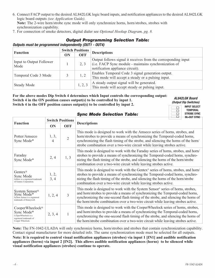
Output Programming Selection Table:Outputs must be programmed independently (OUT1 - OUT4)
FunctionSwitch Positions
DescriptionsON OFF
InputtoOutputFollowerMode
1 2,3Outputfollowssignalitreceivesfromthecorrespondinginput(i.e.FACPSyncmodule-maintainssynchronizationofnotificationappliancecircuit).
TemporalCode3Mode 3 1,2EnablesTemporalCode3signalgenerationoutput.Thismodewillacceptasteadyorapulsinginput.
SteadyMode 1,2,3Asteadyoutputsignalwillbegenerated.Thismodewillacceptsteadyorpulsinginput.
For the above modes Dip Switch 4 determines which Input controls the corresponding output:Switch 4 in the ON position causes output(s) to be controlled by input 1.Switch 4 in the OFF position causes output(s) to be controlled by input 2.
Sync Mode Selection Table:
FunctionSwitch Positions
DescriptionsON OFF
Potter/AmsecoSyncMode*
1,3,4
2
ThismodeisdesignedtoworkwiththeAmsecoseriesofhorns,strobes,andhorn/strobestoprovideameansofsynchronizingtheTemporal-codedhorns,synchronizingtheflashtimingofthestrobe,andsilencingthehornsofthehorn/strobecombinationoveratwo-wirecircuitwhileleavingstrobesactive.
FaradaySyncMode*
2,4 1,3
ThismodeisdesignedtoworkwiththeFaradayseriesofhorns,strobes,andhorn/strobestoprovideameansofsynchronizingtheTemporal-codedhorns,synchro-nizingtheflashtimingofthestrobe,andsilencingthehornsofthehorn/strobecombinationoveratwo-wirecircuitwhileleavingstrobesactive.
Gentex®
SyncModeGentexisaregisteredtrademarkofGentexCorporation.
1,2,3,4
ThismodeisdesignedtoworkwiththeGentex®seriesofhorns,strobes,andhorn/strobestoprovideameansofsynchronizingtheTemporal-codedhorns,synchro-nizingtheflashtimingofthestrobe,andsilencingthehornsofthehorn/strobecombinationoveratwo-wirecircuitwhileleavingstrobesactive.
SystemSensor®SyncMode*SystemSensorisaregisteredtrademarkofHoneywell.
1,2,4 3
ThismodeisdesignedtoworkwiththeSystemSensor®seriesofhorns,strobes,andhorn/strobestoprovideameansofsynchronizingtheTemporal-codedhorns,synchronizingtheone-secondflashtimingofthestrobe,andsilencingthehornsofthehorn/strobecombinationoveratwo-wirecircuitwhileleavingstrobesactive.
CooperWheelock®
SyncMode*CooperWheelockisaregisteredtrademarkofCooperWheelock.
2,3,4 1
ThismodeisdesignedtoworkwiththeCooperWheelockseriesofhorns,strobes,andhorn/strobestoprovideameansofsynchronizingtheTemporal-codedhorns,synchronizingtheone-secondflashtimingofthestrobe,andsilencingthehornsofthehorn/strobecombinationoveratwo-wirecircuitwhileleavingstrobesactive.
Note:TheFN-1042-ULADAwillonlysynchronizehorns,horn/strobesandstrobesthatcontainsynchronizationcapability.Contactsignalmanufacturerformoredetailedinfo.Thesamesynchronizationmodemustbeselectedforalloutputs.Note: It is required to control visual notification appliances (strobes) via input 1 [IN1] and audible notification appliances (horns) via input 2 [IN2]. This allows audible notification appliances (horns) to be silenced while visual notification appliances (strobes) continue to operate.
AL842LGK Board(Output Dip Switches)
INPUT SELECTTEMPORAL
STROBE SYNCIN>OUT SYNC

FN-1042-ULADA - 5 -
Amount of Notification Appliances per NAC:Potter/Amseco 27perNAC* SystemSensor® 32perNAC*Faraday 39perNAC* CooperWheelock® 32perNAC*Gentex® 32perNAC*
*Not to exceed a maximum of 2.5 amp per NAC.
Terminal Identification Table:AL842LGK - Logic BoardTerminal Legend Function/Description
IN1+,IN1-IN2+,IN2-(Supervised)
Theseterminalsconnecttothe12VDCor24VDCFACPnotificationappliancecircuitoutputs.(ClassA,StyleZorClassB,StyleW,Y)Inputtriggervoltageis8-33VDC@5mAmin.Terminalpolarityisshowninalarmcondition.Duringanalarmconditiontheseinputswillcausetheselectedoutputschosentodrivenotificationappliances.Thedesignatedoutputsaresetbyoutputswitches[OUT1throughOUT4](Output Programming Selection Table, pg. 4).AtroubleconditiononanoutputloopwillcausethecorrespondinginputtotriptheFACPbyopeningtheFACPloop.Analarmconditionwillalwaysoverridetroubletodrivenotificationappliances.
RET1+,RET1-RET2+,RET2-(Supervised)
ForClassA,StyleZhookupstheseterminalpairsreturntoFACPNAC1and/orNAC2.ForClassB,StyleW,YhookupstheFACPEOLresistorfromtheNAC1and/orNAC2outputsareterminatedattheseterminals.Optionally,othernotificationappliancesoradditionalsignalingcircuitpowersuppliesmaybeconnectedtotheseterminals.IfthisoptionischosentheEOLresistormustbeterminatedatthelastdevice.
C“DRY1”NCC“DRY2”NC(Dryinputtrigger)
Anopenacrosstheseinputs,willcausetheselectedoutputschosentodrivenotificationappli-ances.Thedesignatedoutputsaresetbyoutputswitches[OUT1throughOUT4](Output Programming Selection Table, pg. 4).NotetheseinputsareunidirectionalandwillnotreportatroubleconditiontotheFACP.
+OUT1--+OUT2--+OUT3--+OUT4--(Supervised)
Notificationappliancesareconnectedtotheseregulatedoutputs(see Application Guide, pgs. 2-4).Eachpower-limitedoutputwillsupply2.5amp.Totalsupplycurrentis10amp(see note below).Outputsarecontrolledbydesignatedinput1[IN1]orinput2[IN2] (Output Programming Selection Table, pg. 4).Maximumlinelossorvoltagedrop(testedwith2.5V).
+Loop1--+Loop2--+Loop3--+Loop4--
UsedforClassA,StyleZhook-upstoterminateloopsoriginatingon[OUT1],[OUT2],[OUT3],and[OUT4]respectively.
C“FAULT”NC(Commontroubleinput)
Anopencircuitacrossthispairofterminalswillcause[INP1andINP2]LEDstosimultaneouslysignalatroubleconditionbacktotheFACP(TypicallyusedtoreportACorBATFail).(Fig. 3a, pg. 8).
NC,C,NO(Commontroubleinput)
Thesearedrycontacttroubleoutputsthatreportanygeneralloop/systemtroubleconditions.(Typicallyusedtotriggeradigitalcommunicatororotherreportingdevices).(form“C”contact1amp/28VDC0.35PowerFactor)(Fig. 3, pg. 8).
--AUX+Thisseparate1ampmax.auxiliaryspecialapplicationpoweroutputcircuitistypicallyusedtopowerelectromagneticdoorholdersthatkeepfireandsmokedoorsopenundernormalconditions.See Appendix A, pgs. 10-11.
--AUX2+
Thisseparateauxiliaryregulatedpoweroutputcircuitsuppliesupto1ampduringstand-byandalarmcondition.SincethisoutputisnotdisconnectedfromitsloadduringACpowerfailureusethe(Battery Calculation Worksheet, pg. 9)todeterminebatterysizeand/orallowablestand-byandalarmcurrent.
+DC-- 24VDCfrompowersupply.
Note: Unit is equipped with two (2) 1 amp max. auxiliary outputs: “AUX1” will automatically disconnect whenAC is lost. “AUX2” will remain battery backed up during power outage. For loads connected to “AUX2” please, refer to battery “Stand-by Specifications” above for ratings. When loads are connected to the “AUX1” and or “AUX2” outputs during alarm condition, the remaining outputs may, not exceed 10 amp total alarm current. (example: AUX1 = 1 amp, AUX2 = 1 amp, outputs up to 8 amp).

- 6 - FN-1042-ULADA
Terminal Identification Table:Power Supply BoardTerminal Legend Function/DescriptionL,N Connect120VACtotheseterminals:LtoHot,NtoNeutral.-DC+ 24VDC@10ampcontinuous,10ampinalarmnonpower-limitedoutput.
ACFAILNO,C,NC
Form“C”drycontactsindicatethelossofAC,withACpresentterminalsmarked[NOandC]areopen,[NCandC]areclosed.WhenlossofACoccursterminalsmarked[NOandC]areclosed,[NCandC]areopen.
ACLOCALNC,NO,C
Form“C”drycontactsusedtoinstantaneouslysignalthelossACtolocalannunciationdevices,withACpresentterminalsmarked[NOandC]areopen,[NCandC]areclosed.WhenlossofACoccursterminalsmarked[NOandC]areclosed,[NCandC]areopen.
BATFAILNO,C,NC
Form“C”drycontactsindicatelowbatteryvoltageorlossofbatteryvoltage.Undernormalconditionsterminalsmarked[N.O.andC]areopen,[NCandC]areclosed.Duringatroubleconditionterminalsmarked[N.O.andC]areclosed,and[N.C.andC]areopen(Fig. 3, pg. 8).
+BAT- Stand-bybatteryinput(leadsprovided)(Fig. 3, pg. 8).
*Power Board Parameter Specifications:• ACFailconditionwillreportapproximately1.5hoursafterlossofAC.TosetACDelayto30seconds,powertheunit down(ACsupplyandBattery)priortochangingswitchposition.Openorclose“ACDelay”switch,respectively.• Lowbatteryconditionwillreportatapproximately20VDC.• Batterypresencedetectionwillreportwithin180secondsafterbatteryremainsundetected(missingorremoved). Arestoredbatterywillreportwithin30seconds.
LED Diagnostics:Power Supply Board
Red (DC) Green (AC) Power Supply StatusON ON Normaloperatingcondition.ON OFF LossofAC,Stand-bybatterysupplyingpower.OFF ON NoDCoutput.OFF OFF LossofAC.Dischargedornostand-bybattery.NoDCoutput.
AL842LGK - Logic Board
LED OFF ON BLINK (LONG)* BLINK (SHORT)**ON Normal AlarmCondition TroubleCondition TroubleConditionMemoryON Normal AlarmCondition TroubleCondition TroubleConditionMemoryOFF Normal AlarmCondition TroubleCondition TroubleConditionMemoryOFF Normal AlarmCondition TroubleCondition TroubleConditionMemoryInput1 Normal AlarmCondition TroubleCondition ---Input2 Normal AlarmCondition TroubleCondition ---Fault Normal AlarmCondition --- ---
* Indicatesexistingtroublecondition.Whenatroublecondition(open,shortorground)occursonaspecificoutput,the correspondingredoutputLED,[OUT1-OUT4]willblink.ThecorrespondinggreeninputLEDwillblinkaswell.**Indicatestroubleconditionmemory.Whenatroubleconditionrestores,theunitsredoutputLEDs,[OUT1-OUT4] willblinkwithashorteranddistinctlydifferentduration.ThegreeninputLEDswillbeoff(normalcondition). ToresetthememorydepresstheresetbuttonlocatedontheAL842LGKlogicboard(Fig. 2c, pg. 8). TheLED(s)willextinguish.
Note: Whenindicatingcircuitshaverestored,troublememoryresetisnotrequiredfornormaloperation.

FN-1042-ULADA - 7 -
NEC Power-Limited Wiring Requirements for FN-1042-ULADA Models:Power-limitedandnonpower-limitedcircuitwiringmustremainseparatedinthecabinet.Allpower-limitedcircuitwiringmustremainatleast0.25”awayfromanynonpower-limitedcircuitwiring.Furthermore,allpower-limitedcircuitwiringandnonpower-limitedcircuitwiringmustenterandexitthecabinetthroughdifferentconduits.Onesuchexampleofthisisshownbelow.Yourspecificapplicationmayrequiredifferentconduitknockoutstobeused.Anycon-duitknockoutsmaybeused.Forpower-limitedapplications,useofconduitisoptional.AllfieldwiringconnectionsmustbemadeemployingsuitablegaugeCMorFPLjacketedwire(orequivalentsubstitute).OptionalbatteryenclosuremustbemountedadjacenttothepowersupplyviaClass1wiringmethods.Note:RefertowirehandlingdrawingbelowfortheproperwaytoinstalltheCMorFPLjacketedwire,(Fig, 2a).
Fig, 2
Fig, 2a
ExternalJacketedShield
Incorrect WireHandling
Correct WireHandling
Pull backexternal jacketedshield approx. 1/2”.
WireInsulation
Solid CopperConductors
120VACInput60Hz
(nonpower-limited)
SupervisoryConnections(power-limited)non-supervised
BatteryConnections(nonpower-limited)supervised
NACCircuits(power-limited)supervisedand
Aux.Output(power-limited)non-supervised
NACCircuits(power-limited)supervised
SignalingCircuitsfromFACP(nonpower-limited)
supervised

- 8 - FN-1042-ULADA
OUT1 OUT2 OUT3 OUT4
INP2 INP1 FAULT
RESET
OUT1 OUT3
OUT2 OUT4IN>OUT SYNCSTROBE SYNC
TEMPORALINPUT SELECT
IN>OUT SYNCSTROBE SYNC
TEMPORALINPUT SELECT
NC
C N
O C
"FA
ULT
" NC
+ DC ---
-- AUX2 + -- LOOP4 + -- OUT4 +-- OUT3 +
-- LOOP3 + -- LOOP1 + -- OUT1 + -- OUT2 +
-- LOOP2 +-- IN1 +
-- RET1 +-- IN2 +
-- RET2 + NC "DRY1" C
NC "DRY2" C-- AUX1 +
Addressablecontrol moduletrigger output
(See Typical Application Diagram for device hookup)
Power-Limited Outputs 2.5 amp per output max. (total = 10 amp)
+ --4-wire Smoke
Detector
+ --4-wire Smoke
Detector
FireAlarmControlPanel(FACP)
EOL PowerSupervision Relay
(Not Supplied)
EOL Resistorfrom FACP
Digital Communicatoror Local AnnunciatorDry output Contact(Form "C" contacts)
These circuits are used tomonitor AC and Bat Fail
and will cause asimultaneous trouble
condition to the FACP'sIN1 and IN2
(Non-Supervised)
Factory Installed BoardInterface Cable
AC
MagneticDoor Holderstand-by battery
connection(non power-limited)
BAT FAIL
AC FAIL
+ BAT – + DC --
DC AC
AC DELAY
NC C
NO NC C
NO
AC LOCAL
NC C NO
L
N
Battery and AC SupervisionCircuit (power-limited).Use separate knockout.
6.3A 250V
15
15A 32V
line
neutralunswitched120VAC
power mains (non power-limited)
Optional hookups:1- BatteryandACmonitoring:ACorBatteryFailconditionwillcausethecommontroubleinput[C“FAULT”NC]to reportbacktotheFACPviainput1andinput2.Thecommontroubleinputmayalsobeusedforotheroptional supervisorymonitoring. ToreportACandBatteryTroubleconnectthebatteryandACFailrelayoutputshowninFig. 3a, pg. 8tothe commontroubleinput.2- Drycontactinput(C“DRY1”NC)(C“DRY2”NC)canbeusedtoalarmoutputfroman addressablemodule(theseinputsareunidirectionandcannotreportbacktotriggermodule). Connection to triggering devices must be made within 20ft. of distance and using conduit for wiring.3- Auxiliaryoutput(-AUX+)24VDCat1ampmax.4- ACLocal[NC,NO,C]shouldconnecttothehostcontrolpanelforlocalannunciationof thetroublecondition.
Note: Ifcommontroubleinput,terminalsmarked[C“FAULT”NC]arenotused,theseterminalsmustbe shorted(connectjumper)toremaininactive.ForoptionalhookupsseeFig. 3b, pg. 8.
Optional Hookup Diagram:Fig. 3 Fig. 3a
Fig. 3b Fig. 3c
Maintenance:Unitshouldbetestedatleastonceayearfortheproperoperationasfollows:Output Voltage Test:Undernormalloadconditions,theDCoutputvoltageshouldbecheckedforpropervoltagelevel(26.2-26.4VDC recommended range).Battery Test:Undernormalloadconditionscheckthatthebatteryisfullycharged.Checkspecifiedvoltagebothatbatteryterminalandattheboardterminalsmarked[+BAT--]toensurethatthereisnobreakinthebatteryconnectionwires.Fuses:Checkinputandoutputfusesonthepowersupplyboard,replaceifnecessary.Inputfuseratingis6.3amp@250V,[email protected]:Maximumchargingcurrentis1.5amp.Note:Expectedbatterylifeis5years;however,itisrecommendedchangingbatteriesin4yearsorlessifneeded.
AC
FAIL
NC
C N
OB
AT
FAIL
NC
C N
O
NC
C
N
O
C "
FAU
LT"
NC
TroubleMemoryResetButton+
DC
--- B
AT
FAIL
NO
C N
C N
O C
NC
+ B
AT
---
L G
N
DC
AC
FAIL
AC
15A
32V
10A
250V
OUT1 OUT2 OUT3 OUT4
INP2 INP1 FAULT
RESET
OUT1 OUT3
OUT2 OUT4IN>OUT SYNCSTROBE SYNC
TEMPORALINPUT SELECT
IN>OUT SYNCSTROBE SYNC
TEMPORALINPUT SELECT
NC
C N
O C
"FA
ULT
" NC
+ DC ---
-- AUX2 + -- LOOP4 + -- OUT4 +-- OUT3 +
-- LOOP3 + -- LOOP1 + -- OUT1 + -- OUT2 +
-- LOOP2 +-- IN1 +
-- RET1 +-- IN2 +
-- RET2 + NC "DRY1" C
NC "DRY2" C-- AUX1 +
Green Lead
Addressablecontrolmoduletriggeroutput
(See Typical Application Diagram for device hookup)
Power-Limited Outputs 2.5 amp per output max. (total = 10 amp)
+ --4-wire Smoke
Detector
+ --4-wire Smoke
Detector
FireAlarmControlPanel(FACP)
EOL PowerSupervision Relay
(Not Supplied)
EOL Resistorfrom FACP
Digi
tal C
omm
unic
ator
or
Loca
l Ann
unci
ator
Dry
ou
tput
Con
tact
(For
m "
C" c
onta
cts)
These circuits are used to monitorAC and Bat Fail and will cause asimultaneous trouble conditionto the FACP's IN1 and IN2(Non-Supervised)
Factory InstalledBoard Interface
Cable
ACFuseCover
unswitched 115VAC 50/60Hz, 4.4 amp
power mains(non power-limited)
MagneticDoor Holder

FN-1042-ULADA - 9 -
Battery Calculation Worksheet
DeviceNumber of Devices
Current per DeviceStand-by Current
Alarm Current
Foreachdeviceusethisformula: Thiscolumn x Thiscolumn = Equals Currentpernumberofdevices.
FN-1042-ULADA(Currentdrawfrombattery)
1Stand-by: 130mA 130mA
Alarm: 300mA 300mA
A FN-1042 Current 130mA 300mA
AuxiliaryDevices Refertodevicemanualforcurrentratings.
Alarm/Stand-by mA mA mA
Alarm/Stand-by mA mA mA
Alarm/Stand-by mA mA mA
B Auxiliary Devices Current (must not exceed 1 amp)
Refertodevicemanualforcurrentratings.
Alarm: mA 0mA mA
Alarm: mA 0mA mA
Alarm: mA 0mA mA
Alarm: mA 0mA mA
C NotificationAppliancesCurrent must notexceed10amp(10,000mA) 0mA mA
D Totalalarmcurrent mA mA
E Totalcurrentratingsconvertedtoamperes(lineDx0.001) A A
F Numberofstand-byhours(24forNFPA72,Chapter1,1-5.2.5). H
G MultiplylinesEandF. Totalstand-byAH AH
H Alarmsoundingperiodinhours.(Forexample,5minutes=.0833hours.)
H
I MultiplylinesEandH. TotalalarmAH AH
J AddlinesGandI. Totalstand-byandalarmAH AH
KMultiplylineJby1.30.(30%extrainsurancetomeetdesiredperformance)Totalampere-hoursrequired
AH
Unitsarecapableofrecharging36AHbatterymax.Iftotalampere-hourrequiredexceeds36AH,decreaseAUXcurrenttoprovideenoughstand-bytimefortheapplication.

- 10 - FN-1042-ULADA
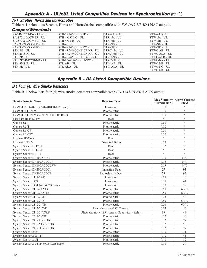
Appendix A - UL/cUL Listed Compatible Devices for Synchronization
A-1 Strobes, Horns and Horn/StrobesTableA-1belowlistsStrobes,HornsandHorn/StrobescompatiblewithFN-1042-ULADANACoutputs.Gentex:GCS24CR-UL GCCB24PCR/W-UL GEC24-15/75WR-ULGCS24CW-UL GCCG24PCR/W-UL GEC24-15/75WW-ULGCS24PCR-UL GCCR24PCR/W-UL SSPK24CLPR-ULGCS24PCW-UL WGESA24-75PWR/W-UL SSPK24CLPW-ULGCC24CR-UL WGESB24-75PWR/W-UL SSPK24WLPR-ULGCC24PCR-UL WGESG24-75PWR/W-UL SSPK24WLPW-ULGCC24CW-UL WGESR24-75PWR/G-UL SSPK24AWR-ULGCC24PCW-UL WGECA24-75PWR/W-UL SSPK24AWW-ULGES3-24WR-UL WGECB24-75PWR/W-UL SSPK24-15/75WLPR-ULGEC3-24WR-UL WGECG24-75PWR/W-UL SSPK24-15/75WLPW-ULGEH24-R-UL WGECR24-75PWR/G-UL SSPK24-15/75AWR-ULGEH24-W-UL WGESA24-75PWLPR/W-UL SSPK24-15/75AWW-ULWGES24-75WR/WW-UL WGESB24-75PWLPR/W-UL SSPKA24-15/75PWR-ULWGES24-75PWR/PWW-UL WGESG24-75PWLPR/W-UL SSPKA24-15/75PWW-ULWGES24-75WRLP/WWLP-UL WGESR24-75PWLPR/W-UL SSPKA24-15/75AWR-ULWGEC24-75WR/WW-UL WGECA24-75PWLPR/W-UL SSPKA24-15/75AWW-ULWGEC24-75PWR/PWW-UL WGECB24-75PWLPR/W-UL SSPKB24-15/75PWR-ULWGEC24-75WRLP/WWLP-UL WGECG24-75PWLPR/W-UL SSPKB24-15/75PWW-ULWGEC24-75PWRLP/WWLP-UL WGECR24-75PWLPR/W-UL SSPKG24-15/75PWR-ULGESA24PWR/W-UL GX91-R/W-UL/cUL SSPKG24-15/75PWW-ULGESB24PWR/W-UL GX91-PR/W-UL/cUL SSPKR24-15/75PWR-ULGESG24PWR/W-UL GX93-R/W-UL/cUL SSPKR24-15/75PWW-ULGESR24PWR/W-UL GX93-PR/W-UL/cUL WSSPKA24-15/75AWR-ULGECA24PWR/W-UL WSSPK24-15/75WR/WW-UL WSSPKA24-15/75AWW-ULGECB24PWR/W-UL WSSPK24-15/75PWR/PWW-UL WSSPKA24-15/75PWR-ULGECG24PWR/W-UL WSSPK24-15/75AWR/AWW-UL WSSPKA24-15/75PWW-ULGECR24PWR/W-UL GES24-177WR-UL WSSPKB24-15/75PWR-ULGCSA24PCR/W-UL GES24-177WW-UL WSSPKB24-15/75PWW-ULGCSB24PCR/W-UL GES24-15/75WR-UL WSSPKG24-15/75PWR-ULGCSG24PCR/W-UL GES24-15/75WW-UL WSSPKG24-15/75PWW-ULGCSR24PCR/W-UL GEC24-177WR-UL WSSPKR24-15/75PWR-ULGCCA24PCR/W-UL GEC24-177WW-UL WSSPKR24-15/75PWW-UL
System Sensor:CHSR-UL P4R-SP-UL PC4RH-P-UL SPSCW-UL SPSWK-CLR-ALERT-ULCHSW-UL P4RH-UL PC4RH-SP-UL SPSCW-CLR-ALERT-UL SPSWK-P-ULHR/HRK/HW-UL P4RH-P-UL PC4W-UL SPSCW-P-UL SPSWK-R-ULMHR-UL P4RH-SP-UL PC4W-P-UL SPSCWH-UL SPSWV-ULMHW-UL P4RK-UL PC4W-SP-UL SPSCWH-P-UL SPSWV-P-ULP1224MC-UL P4RK-R-UL PC4WH-UL SPSCWHK-UL SR-ULP2R-UL P4W-UL PC4WH-P-UL SPSCWHK-P-UL SR-P-ULP2R-P-UL P4W-P-UL PC4WH-SP-UL SPSCWK-UL SR-SP-ULP2R-SP-UL P4W-SP-UL PC4WHK-UL SPSCWK-CLR-ALERT-UL SRH-ULP2RH-UL P4WH-UL PC4WK-UL SPSCWK-R-UL SRH-P-ULP2RH-LF-UL P4WH-P-UL SCR-UL SPSCWV-UL SRH-SP-ULP2RH-P-UL P4WH-SP-UL SCR-P-UL SPSCWV-P-UL SRHK-ULP2RH-SP-UL P4WK-UL SCR-SP-UL SPSCWVH-UL SRHK-P-ULP2RHK-UL PC2R-UL SCRH-UL SPSCWVH-P-UL SRHK-R-ULP2RHK-P-UL PC2R-P-UL SCRH-P-UL SPSR-UL SRK-ULP2RHK-R-UL PC2RH-UL SCRH-SP-UL SPSR-P-UL SRK-P-ULP2RK-UL PC2RH-P-UL SCRHK-UL SPSRH-UL SRK-R-ULP2RK-P-UL PC2RH-SP-UL SCRK-UL SPSRH-P-UL SW-ULP2RK-R-UL PC2RHK-UL SCW-UL SPSRHK-UL SW-ALERT-ULP2W-UL PC2RK-UL SCW-CLR-ALERT-UL SPSRK-UL SW-CLR-ALERT-ULP2W-P-UL PC2W-UL SCW-P-UL SPSRK-P-UL SW-P-ULP2W-SP-UL PC2W-P-UL SCW-SP-UL SPSRK-R-UL SW-SP-ULP2WH-UL PC2W-SP-UL SCWH-UL SPSRV-UL SWH-ULP2WH-LF-UL PC2WH-UL SCWH-P-UL SPSRV-P-UL SWH-ALERT-ULP2WH-P-UL PC2WH-P-UL SCWH-SP-UL SPSW-UL SWH-P-ULP2WH-SP-UL PC2WH-SP-UL SCWHK-UL SPSW-ALERT-UL SWH-SP-ULP2WHK-UL PC2WHK-UL SCWK-UL SPSW-CLR-ALERT-UL SWHK-ULP2WHK-P-UL PC2WK-UL SPSCR-UL SPSW-P-UL SWHK-P-ULP2WK-UL PC4R-UL SPSCRH-UL SPSWH-UL SWK-ULP2WK-P-UL PC4R-P-UL SPSCRV-UL SPSWH-P-UL SWK-P-ULP4R-UL PC4R-SP-UL SPSCRVH-UL SPSWK-ULP4R-P-UL PC4RH-UL

FN-1042-ULADA - 11 -
Appendix A - UL/cUL Listed Compatible Devices for Synchronization (cont’d)
A-1 Strobes, Horns and Horn/StrobesTableA-1belowlistsStrobes,HornsandHorn/StrobescompatiblewithFN-1042-ULADA NACoutputs.Potter/Amseco:CM24CR-UL CSL-1224W-BW-UL/cUL MH-12/24W-UL/cUL SSC8-177R-ULCM24CW-UL CSL-1224W-GR-UL/cUL SCM24C-177R-UL SSC8-177W-ULCSH-1224W-AR-UL/cUL CSL-1224W-GW-UL/cUL SCM24C-177W-UL SSC8-3075110R-ULCSH-1224W-AW-UL/cUL CSL-1224W-RR-UL/cUL SCM24C-3075110R-UL SSC8-3075110W-ULCSH-1224W-BR-UL/cUL CSL-1224W-RW-UL/cUL SCM24C-3075110W-UL SSR2-177R-ULCSH-1224W-BW-UL/cUL CSL24CAW-UL/cUL SH-1224R-UL/cUL SSR2-177W-ULCSH-1224W-GR-UL/cUL CSL24C-BW-UL/cUL SH-1224W-UL/cUL SSR2-3075110R-ULCSH-1224W-GW-UL/cUL CSL24C-GW-UL/cUL SH-1224WP-R-UL/cUL SSR2-3075110W-ULCSH-1224W-RR-UL/cUL CSL24C-RW-UL/cUL SH-1224WP-W-UL/cUL SSR8-177R-ULCSH-1224W-RW-UL/cUL CSL24C-AR-UL/cUL SH24C-177R-UL/cUL SSR8-177W-ULCSH24C-AW-UL/cUL CSL24C-BR-UL/cUL SH24C-177W-UL/cUL SSR8-3075110R-ULCSH24C-BW-UL/cUL CSL24C-GR-UL/cUL SL-1224R-UL/cUL SSR8-3075110W-ULCSH24C-GW-UL/cUL CSL24C-RR-UL/cUL SL-1224W-UL/cUL SSS2-1530R-ULCSH24C-RW-UL/cUL H-1224R-UL/cUL SL-1224WP-R-UL/cUL SSS2-1530W-ULCSH24C-AR-UL/cUL H-1224W-UL/cUL SL-1224WP-W-UL/cUL SSS2-75110R-ULCSH24C-BR-UL/cUL HP-25TR-UL/cUL SL-24W-UL/cUL SSS2-75110W-ULCSH24C-GR-UL/cUL HP-25TW-UL/cUL SSC2-177R-UL SSS8-1530R-ULCSH24C-RR-UL/cUL MH-12/24R-UL/cUL SSC2-177W-UL SSS8-1530W-ULCSL-1224W-AR-UL/cUL MH-12/24TR-UL/cUL SSC2-3075110R-UL SSS8-75110R-ULCSL-1224W-AW-UL/cUL MH-12/24TW-UL/cUL SSC2-3075110W-UL SSS8-75110W-ULCSL-1224W-BR-UL/cUL
Cooper/Wheelock:50-241575W-FR-UL/cUL E70-24MCW-FN-UL/cUL ET90-24MCCH-FN-UL/cUL LSTW-A*-UL/cULAH-24WP-R-UL E70-24MCW-FR-UL/cUL ET90-24MCCH-FW-UL/cUL LSTW-ALA*-UL/cULAMT-12/24-R-UL/cUL E70-24MCW-FW-UL/cUL HNR-UL/cUL LSTW-NA*-UL/cULAMT-12/24-W-UL/cUL E70-24MCWH-FN-UL/cUL HNRC-UL/cUL LSTW-NA*-UL/cULAMT-241575W-FR-UL/cUL E70-24MCWH-FR-UL/cUL HNW-UL/cUL MIZ-24S-R-UL/cULAMT-241575W-FR-NYC-UL E70-24MCWH-FR-UL/cUL HNWC-UL/cUL MIZ-24S-W-UL/cULAMT-241575W-FW-UL/cUL E70-24MCWH-FW-UL/cUL HS-24-R-UL/cUL MT-12/24-R-ULAMT-24MCW-FR-UL/cUL E70H-241575W-FR-UL/cUL HS-24-W-UL/cUL MT-241575W-FR-UL/cULAMT-24MCW-FW-UL/cUL E70H-241575W-FW-UL/cUL HS4-241575W-FR-UL/cUL MT-241575W-FW-UL/cULAS-12100C-UL/cUL E70H-24MCW-FR-UL/cUL HS4-24MCC-FR-UL MT-24MCW-FR-UL/cULAS-24100C-UL/cUL E70H-24MCW-FW-UL/cUL HS4-24MCC-FW-UL/cUL MT-24MCW-FW-UL/cULASWP-2475C-FR-UL E70H-24MCWH-FN-UL/cUL HS4-24MCW-FR-UL/cUL MTWP-2475C-FR-ULASWP-2475C-FW-UL E70H-24MCWH-FW-UL/cUL HS4-24MCW-FW-UL/cUL MTWP-2475C-FW-ULASWP-2475W-FR-UL E90-24MCC-FN-UL/cUL HSR-UL/cUL MTWP-2475W-FR-ULASWP-2475W-FW-UL ET90-24MCC-FW-UL/cUL HSRC-UL/cUL MTWP-2475W-FW-ULASWP-24MCCH-FR-UL ET90-24MCC-FN-UL/cUL HSW-UL/cUL MTWP-24MCCH-FR-ULASWP-24MCCH-FW-UL E90-24MCC-FR-UL/cUL HSWC-UL/cUL MTWP-24MCCH-FW-ULASWP-24MCWH-FR-UL E90-24MCC-FW-UL/cUL LHNR*-UL/cUL MTWP-24MCWH-FR-ULASWP-24MCWH-FW-UL E90-24MCCH-FN-UL/cUL LHNW*-UL/cUL MTWP-24MCWH-FW-ULCH70-24MCW-FR-UL/cUL E90-24MCCH-FR-UL/cUL LHSR*-UL/cUL RSS-241575W-FR-UL/cULCH70-24MCW-FW-UL/cUL E90-24MCCH-FW-UL/cUL LHSR-A*-UL/cUL RSS-241575W-FW-UL/cULCH70-24MCWH-FR-UL/cUL E90H-24MCC-FR-UL/cUL LHSR-AL*-UL/cUL RSS-24MCW-FR-UL/cULCH70-24MCWH-FW-UL/cUL E90H-24MCC-FW-UL/cUL LHSR-N*-UL/cUL RSS-24MCW-FW-UL/cULCH90-24MCC-FR-UL/cUL E90H-24MCCH-FR-UL/cUL LHSW*-UL/cUL RSS-24MCWH-FR-UL/cULCH90-24MCC-FW-UL/cUL E90H-24MCCH-FW-UL/cUL LHSW-A*-UL/cUL RSS-24MCWH-FW-UL/cULCH90-24MCCH-FR-UL/cUL EET90-24MCCH-FR-UL/cUL LHSW-AL*-UL/cUL RSSA-24MCC-NW-ULCH90-24MCCH-FW-UL/cUL ET-1010-R-UL LHSW-N*-UL/cUL RSSA-24MCCH-NW-ULE50-241575W-FW-UL/cUL ET-1010-W-UL LSPSTR*-UL/cUL RSSB-24MCC-NW-ULE50-24MCWH-FR-UL/cUL ET70-241575W-FR-UL/cUL LSPSTR-AL*-UL/cUL RSSB-24MCCH-NW-ULE50-24MCWH-FW-UL/cUL ET70-241575W-FW-UL/cUL LSPSTR-ALA*-UL/cUL RSSG-24MCC-NW-ULE50H-241575W-FR-UL/cUL ET70-24MCW-FN-UL/cUL LSPSTR-N*-UL/cUL RSSG-24MCCH-NW-ULE50H-241575W-FW-UL/cUL ET70-24MCW-FR-UL/cUL LSPSTR-NA*-UL/cUL RSSR-24MCC-NW-ULE50H-24MCW-FR-UL/cUL ET70-24MCW-FW-UL/cUL LSPSTW*-UL/cUL RSSR-24MCCH-NW-ULE50H-24MCW-FW-UL/cUL ET70-24MCWH-FN-UL/cUL LSPSTW-AL*-UL/cUL RSSWP-2475C-FR-ULE50H-24MCWH-FR-UL/cUL ET70-24MCWH-FR-UL/cUL LSPSTW-ALA*-UL/cUL RSSWP-2475C-FW-ULE50H-24MCWH-FW-UL/cUL ET70-24MCWH-FW-UL/cUL LSPSTW-N*-UL/cUL RSSWP-2475W-AR-ULE60-24MCC-FR-UL/cUL ET70WP-24185W-FR-UL LSPSTW-NA*-UL/cUL RSSWP-2475W-FR-ULE60-24MCC-FW-UL/cUL ET70WP-24185W-FW-UL LSTR*-UL/cUL RSSWP-2475W-FW-ULE60-24MCCH-FR-UL/cUL ET70WP-2475C-FR-UL LSTR-A*-UL/cUL RSSWP-2475W-NW-ULE60-24MCCH-FW-UL/cUL ET70WP-2475C-FW-UL LSTR-AL*-UL/cUL RSSWP-24MCCH-FR-ULE60H-24MCC-FR-UL/cUL ET80-24MCW-FR-UL/cUL LSTR-ALA*-UL/cUL RSSWP-24MCCH-FW-ULE60H-24MCC-FW-UL/cUL ET80-24MCW-FW-UL/cUL LSTR-NA*-UL/cUL RSSWP-24MCWH-FR-ULE60H-24MCCH-FR-UL/cUL ET80-24MCWH-FR-UL/cUL LSTRW-ALA*-UL/cUL RSSWP-24MCWH-FW-ULE60H-24MCCH-FW-UL/cUL ET80-24MCWH-FW-UL/cUL LSTW*-UL/cUL S8-24MCC-FW-UL/cUL*WhenusingthesemodelstrobesthemaximumcurrentperNACislimitedto2amp.
- 12 - FN-1042-ULADA
Appendix A - UL/cUL Listed Compatible Devices for Synchronization (cont’d)
A-1 Strobes, Horns and Horn/StrobesTableA-1belowlistsStrobes,HornsandHorn/StrobescompatiblewithFN-1042-ULADA NACoutputs.Cooper/Wheelock:S8-24MCCH-FW-UL/cUL STH-3R24MCCH-NR-UL STR-ALB-UL STW-ALB-ULSA-S70-24MCW-FR-UL STH-4M30WC-UL STR-NA-UL STW-NA-ULSA-S70-24MCW-FW-UL STH-4MS-R-UL STR-NB-UL STW-NB-ULSA-S90-24MCC-FR-UL STH-4R-UL STR-NG-UL STW-NG-ULSA-S90-24MCC-FW-UL STH-4R24MCCH-NW-UL STR-NR-UL STW-NR-ULSTH-2G-UL STH-4R24MCCH110B-NR-UL STRC-NA-UL STWC-AB-ULSTH-2MS-R-UL STH-4R24MCCH110R-NA-UL STRC-NB-UL STWC-ALA-ULSTH-2R-UL STH-4R24MCCH110R-NR-UL STRC-NG-UL STWC-ALB-ULSTH-2R24MCCH-NR-UL STH-90-4R24MCCH-NW-UL STRC-NR-UL STWC-NA-ULSTH-3MS-R-UL STR-AB-UL STW-AB-UL STWC-NB-ULSTH-3R-UL STR-ALA-UL STW-ALA-UL STWC-NG-UL
STWC-NR-UL
Appendix B - UL Listed Compatible Devices
B.1 Four (4) Wire Smoke DetectorsTableB-1belowlistsfour(4)wiresmokedetectorscompatiblewithFN-1042-ULADAAUXoutput.
Smoke Detector/Base Detector Type Max Stand-by Current (mA)
Alarm Current (mA)
FenWalCPD-7021(w/70-201000-005Base) Ionization 0.10 *FenWalPSD-7125 Photoelectric 0.10 *FenWalPSD-7125(w/70-201000-005Base) Photoelectric 0.10 *Fire-LiteBLP-12-4W Base * *Gentex824 Photoelectric 0.50 *Gentex824T Photoelectric 0.50 *Gentex824CP Photoelectric 0.50 *Gentex824CPT Photoelectric 0.50 *HochikiHSC-4R Base * *HochikiSPB-24 ProjectedBeam 0.25 *SystemSensorB112LP Base 0.12 36SystemSensorB114LP Base * *SystemSensorB404B Base * *SystemSensorDH100ACDC Photoelectric 0.15 0.70SystemSensorDH100ACDCLP Photoelectric 0.15 0.70SystemSensorDH100ACDCLPW Photoelectric 0.15 0.70SystemSensorDH400ACDCI IonizationDuct 25 95SystemSensorDH400ACDCP PhotoelectricDuct 25 95SystemSensor1112/24/D Ionization 0.05 50SystemSensor1424 Ionization 0.10 41SystemSensor1451(w/B402BBase) Ionization 0.10 39SystemSensor2112/24ATR Photoelectric 0.50 60/70SystemSensor2112/24AITR Photoelectric 0.50 60/70SystemSensor2112/24/D Photoelectric 0.05 50SystemSensor2112/24R Photoelectric 0.50 60/70SystemSensor2112/24TR Photoelectric 0.50 60/70SystemSensor2112/24T/D Photoelectricw/135
oThermal 0.05 50SystemSensor2112/24TSRB Photoelectricw/135
oThermalSupervisoryRelay 15 45
SystemSensor2312/24TB Photoelectric 0.12 50SystemSensor2412(12volt) Photoelectric 0.12 77SystemSensor2412AT(12volt) Photoelectric 0.12 58SystemSensor2412TH(12volt) Photoelectric 0.12 77SystemSensor2424 Photoelectric 0.10 41SystemSensor2424TH Photoelectric 0.10 41SystemSensor2451 Photoelectric 0.10 39SystemSensor2451TH(w/B402BBase) Photoelectric 0.10 39

FN-1042-ULADA - 13 -
Appendix B - UL Listed Compatible Devices
B.1 Four (4) Wire Smoke DetectorsTableB-1belowlistsfour(4)wiresmokedetectorscompatiblewithFN-1042-ULADAAUXoutput.
Smoke Detector/Base Detector Type Max Stand-by Current (mA)
Alarm Current (mA)
SystemSensor2W-MOD LoopTest/MaintenanceMod. 30 50SystemSensor4W-B(12/24volt) PhotoelectricI3 0.05 23SystemSensor4WT-B(12/24volt) PhotoelectricI3w/Therm 0.05 23SystemSensor4WTA-B(12/24volt) I3Photow/Therm/Sounder 0.05 35SystemSensor4WTR-B(12/24volt) I3Photow/Therm/Relay 0.05 35SystemSensor4WTR-B(12/24volt) I3Photow/Therm/Sounder/Relay 0.05 50SystemSensor4WITAR-B(12/24volt) I3Photow/IsolatedTherm/Sounder/Relay 0.05 50SystemSensor2W-MOD2 I3LoopTest/MaintenanceMod. 0.05 *SystemSensorRRS-MOD I3ReversingRelay/SyncModule 0.05 *SystemSensor6424 ProjectedBeam 10 28.4SystemSensorBeam1224(S) ProjectedBeam 17 38.5*Contactmanufacturerforcurrentdraws
B.2 Door Holders
TableB-2belowlistsdoorholderscompatiblewithFN-1042-ULADAAUXoutput.
Manufacturer Model Type Current (mA)Edwards DH150A FloorMount 96Edwards DH154A FloorMount 96Edwards DH158A SurfaceMount 96RixonFiremark FM-980 FloorMount,single 68RixonFiremark FM-996 SurfaceWiring 68RixonFiremark FM-998 ConcealedWiring 68
B.3 Relays
TableB-3belowlistsrelayscompatiblewithFN-1042-ULADAAUXoutput.
Manufacturer Model Current (mA) Manufacturer Model Current
(mA) Manufacturer Model Current (mA)
AirProducts&Controls,LTD
MR-101/C 15
SystemSensor
PR-1 15
SystemSensor
R-20T 40MR-201/C 35 PR-2 30 R-24T 40PAM-1 15 PR-3 30 R-10E 23PAM-2 15 EOLR-1 30 R-14E 23PAM-SD 15 R-10T 23 R-20E 40A77-716B 20 R-14T 23 R-24E 40

- 14 - FN-1042-ULADA
Notes:

FN-1042-ULADA - 15 -
Notes:
- 16 - FN-1042-ULADA
HochikiAmericaCorp.7051VillageDrive,Suite100BuenaPark,CA90621-2268,714-522-2246,Fax:714-690-7890,www.hochiki.comIIFN-1042-ULADA L11M
1.5”(38.1mm)
1.0”(25.4mm)
4.5”(114.3mm)
1.0”(25.4mm)
1.0”(25.4mm)
1.25”(31.75mm)
1.25”(31.75mm)
1.0”(25.4mm)
1.5”(38.1mm)
1.5”(38.1mm)
1.5”(38.1mm)
1.5”(38.1mm)
8.5”(215.9mm)
18.0”(457.2mm)
18.0”(457.2mm)
18.0”(457.2mm)
6.0”(152.4mm)
2.5”(63.5mm)
2.75”(69.85mm)
2.75”(69.85mm)
4.5”(114.3mm)
4.5”(114.3mm)
14.5”(368.3mm)
14.5”(368.3mm)
1.0”(25.4mm)
1.0”(25.4mm)
14.5”(368.3mm)
2.5”(63.5mm)
1.5”(38.1mm)
2.5”(63.5mm)
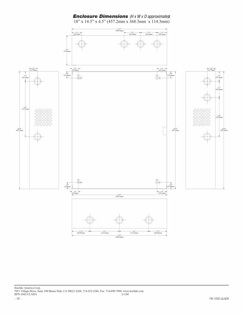
Enclosure Dimensions (H x W x D approximate):18”x14.5”x4.5”(457.2mmx368.3mmx114.3mm)