FM3001 User Manual - gpswox.com User Manual v0... · 2 Table of contents. 1 INTRODUCTION..... 7
100
FM3001 User Manual V0.08
Transcript of FM3001 User Manual - gpswox.com User Manual v0... · 2 Table of contents. 1 INTRODUCTION..... 7

FM3001 User Manual V0.08

2
Table of contents 1 INTRODUCTION .......................................................................................................................... 7
1.1 ATTENTION ................................................................................................................................... 7 1.2 INSTRUCTIONS OF SAFETY ................................................................................................................. 7 1.3 LEGAL NOTICE ................................................................................................................................ 8 1.4 ABOUT DOCUMENT ......................................................................................................................... 8
2 BASIC DESCRIPTION .................................................................................................................... 8
2.1 BASIC CHARACTERISTICS ................................................................................................................... 9 2.2 TECHNICAL FEATURES .................................................................................................................... 10 2.3 TECHNICAL INFORMATION ABOUT INTERNAL BATTERY .......................................................................... 11 2.4 ELECTRICAL CHARACTERISTICS ......................................................................................................... 11 2.5 ABSOLUTE MAXIMUM RATINGS ...................................................................................................... 11
3 CONNECTION, PINOUT, ACCESSORIES ...................................................................................... 12
3.1 HOW TO INSERT MICRO SIM CARD INTO FM3001 DEVICE: .................................................................. 12 3.2 INSTALLING FM3001 DRIVERS ........................................................................................................ 13 3.3 OBD II ....................................................................................................................................... 15 3.4 NAVIGATE LED ............................................................................................................................ 16 3.5 STATUS LED ................................................................................................................................ 16
4 OPERATIONAL BASICS .............................................................................................................. 16
4.1 OPERATIONAL PRINCIPALS .............................................................................................................. 16 4.2 SLEEP MODE ................................................................................................................................ 17
4.2.1 Sleep mode ...................................................................................................................... 17 4.2.2 Deep Sleep mode ............................................................................................................. 17 4.2.3 Online Deep Sleep mode .................................................................................................. 18
4.3 VIRTUAL ODOMETER ..................................................................................................................... 18 4.4 FEATURES ................................................................................................................................... 18
4.4.1 Green Driving Scenario .................................................................................................... 18 4.4.2 Over Speeding Scenario. .................................................................................................. 19 4.4.3 Excessive Idling ................................................................................................................ 19 4.4.4 Jamming detection .......................................................................................................... 19 4.4.5 Trip ................................................................................................................................... 19
4.5 ACCELEROMETER SCENARIOS........................................................................................................... 19 4.5.1 Towing Detection ............................................................................................................. 19 4.5.2 Unplug Detection ............................................................................................................. 20 4.5.3 Crash Detection ............................................................................................................... 20
4.5.3.1 Crash Trace operation ............................................................................................................ 20 4.5.3.2 blue-tooth ............................................................................................................................... 20
5 CONFIGURATION ...................................................................................................................... 20
5.1 STATUS WINDOW ......................................................................................................................... 24 5.2 SECURITY SETTINGS ....................................................................................................................... 25 5.3 SYSTEM SETTINGS ......................................................................................................................... 25 5.4 GPRS SETTINGS ........................................................................................................................... 28 5.5 DATA ACQUISITION SETTINGS .......................................................................................................... 29 5.6 SMS / CALL SETTINGS ................................................................................................................... 32 5.7 GSM OPERATORS LIST .................................................................................................................. 34 5.8 FEATURES SETTINGS ...................................................................................................................... 34
5.8.1 Green Driving ................................................................................................................... 35 5.8.2 Over Speeding .................................................................................................................. 36 5.8.3 Jamming .......................................................................................................................... 36 5.8.4 GNSS Fuel Counter ........................................................................................................... 36
5.9 ACCELEROMETER FEATURES SETTINGS ............................................................................................... 37 5.9.1 Excessive Idling ................................................................................................................ 38 5.9.2 Towing Detection ............................................................................................................. 38

3
5.9.3 Crash Detection ............................................................................................................... 39 5.9.4 Unplug Detection ............................................................................................................. 40
5.10 AUTO GEOFENCE SETTINGS ........................................................................................................... 40 5.11 MANUAL GEOFENCE ................................................................................................................... 41 5.12 TRIP / ODOMETER SETTINGS ......................................................................................................... 43 5.13 BLUE-TOOTH SETTINGS ................................................................................................................. 44
5.13.1 How to connect blue-tooth Hands Free adapter to FM3001 device .............................. 47 5.13.2 Device’s log using your mobile phone. ........................................................................... 49
5.14 I/O SETTINGS ............................................................................................................................. 49 5.15 OBD FUNCTIONALITY DESCRIPTION ................................................................................................ 51
5.15.1 Supported OBD protocols .............................................................................................. 51 5.15.2 General info ................................................................................................................... 51 5.15.3 Initialization ................................................................................................................... 52 5.15.4 Data ............................................................................................................................... 52 5.15.5 ELD ................................................................................................................................. 52
6 SMS COMMAND LIST................................................................................................................ 53
6.1 BASIC COMMANDS ........................................................................................................................ 53 6.1.1.1 getinfo .................................................................................................................................... 53 6.1.1.2 getver...................................................................................................................................... 54 6.1.1.3 getstatus ................................................................................................................................. 54 6.1.1.4 getgps ..................................................................................................................................... 54 6.1.1.5 ggps ........................................................................................................................................ 55 6.1.1.6 readio # ................................................................................................................................... 55 6.1.1.7 getparam ................................................................................................................................ 55 6.1.1.8 setparam ................................................................................................................................. 55 6.1.1.9 flush #,#,#,#,#,#,# ................................................................................................................... 55 6.1.1.10 countrecs .............................................................................................................................. 56 6.1.1.11 towingreact........................................................................................................................... 56 6.1.1.12 faultcodes ............................................................................................................................. 56 6.1.1.13 obdinfo ................................................................................................................................. 56 6.1.1.14 btgetlist ................................................................................................................................. 56 6.1.1.15 cleardtc ................................................................................................................................. 56
6.2 SYSTEM PARAMETERS: ................................................................................................................... 56 6.2.1.1 Movement Source (ID=100).................................................................................................... 56 6.2.1.2 Records Saving/Sending Without TS (ID=107) ........................................................................ 57 6.2.1.3 Led Indication (ID=108)........................................................................................................... 57 6.2.1.4 GNSS Source (ID=109) ............................................................................................................. 57 6.2.1.5 Battery Charge Mode (ID=110) ............................................................................................... 57 6.2.1.6 Static Navigation (ID=106) ...................................................................................................... 57 6.2.1.7 Static Navigation Settings (ID=112) ........................................................................................ 58 6.2.1.8 Sleep Mode (ID=102) .............................................................................................................. 58 6.2.1.9 Sleep Timeout (ID=103) .......................................................................................................... 58 6.2.1.10 Ignition Settings (ID=101) ..................................................................................................... 58 6.2.1.11 High voltage level (ID=104) ................................................................................................... 58 6.2.1.12 Low voltage level (ID=105) ................................................................................................... 58 6.2.1.13 Movement start delay (ID=19001) ........................................................................................ 59 6.2.1.14 Movement stop delay (ID=19002) ........................................................................................ 59 6.2.1.15 Time Synchronization (ID=900) ............................................................................................. 59 6.2.1.16 NTP Resync (ID=901)............................................................................................................. 59 6.2.1.17 NTP Server 1 (ID=902)........................................................................................................... 59 6.2.1.18 NTP Server 2 (ID=903)........................................................................................................... 59
6.3 GPRS PARAMETERS ...................................................................................................................... 59 6.3.1.1 GPRS Context (ID=2000) ......................................................................................................... 59 6.3.1.2 APN (ID=2001) ........................................................................................................................ 60 6.3.1.3 APN Username (ID=2002) ....................................................................................................... 60 6.3.1.4 APN Password (ID=2003) ........................................................................................................ 60 6.3.1.5 Domain (ID=2004) ................................................................................................................... 60 6.3.1.6 Target Server Port (ID=2005) .................................................................................................. 60 6.3.1.7 Protocol (ID=2006) .................................................................................................................. 61 6.3.1.8 Backup Server Mode (ID=2010) .............................................................................................. 61 6.3.1.9 Backup Server Domain (ID=2008) ........................................................................................... 61

4
6.3.1.10 Backup Server Port (ID=2008) ............................................................................................... 61 6.3.1.11 Protocol (ID=2009) ................................................................................................................ 61 6.3.1.12 Open Link Timeout (ID=1000) ............................................................................................... 62 6.3.1.13 Response Timeout (ID=1001) ............................................................................................... 62 6.3.1.14 Sort By (ID=1002) .................................................................................................................. 62 6.3.1.15 FOTA WEB Settings: Status (ID=13003) ................................................................................ 62 6.3.1.16 FOTA WEB Settings: Domain (ID=13000) .............................................................................. 62 6.3.1.17 FOTA WEB Settings: Port (ID=13001).................................................................................... 63 6.3.1.18 FOTA WEB Settings: Period (ID=13002) ................................................................................ 63
6.4 DATA ACQUISITION SETTINGS .......................................................................................................... 63 6.4.1 Home Network GSM operator code “On stop” parameters ............................................ 63
6.4.1.1 Min Period (ID=10000) ........................................................................................................... 63 6.4.1.2 Min Saved Records (ID=10004) ............................................................................................... 63 6.4.1.3 Send Period (ID=10005) .......................................................................................................... 63
6.4.2 Home Network GSM operator code “Moving” parameters ............................................. 64 6.4.2.1 Min Period (ID=10050) ........................................................................................................... 64 6.4.2.2 Min Distance (ID=10051) ........................................................................................................ 64 6.4.2.3 Min Angle (ID=10052) ............................................................................................................. 64 6.4.2.4 Min Speed delta (ID=10053) ................................................................................................... 64 6.4.2.5 Min Saved Records (ID=10054) ............................................................................................... 64 6.4.2.6 Send Period (ID=10055) .......................................................................................................... 65
6.4.3 Roaming Network GSM operator code “On stops” parameters ...................................... 65 6.4.3.1 Min Period (ID=10100) ........................................................................................................... 65 6.4.3.2 Min Saved Records (ID=10104) ............................................................................................... 65 6.4.3.3 Send Period (ID=10105) .......................................................................................................... 65
6.4.4 Roaming Network GSM operator code “Moving” parameters ........................................ 65 6.4.4.1 Min Period (ID=10150) ........................................................................................................... 65 6.4.4.2 Min Distance (ID=10151) ........................................................................................................ 65 6.4.4.3 Min Angle (ID=10152) ............................................................................................................. 66 6.4.4.4 Min Speed (ID=10153) ............................................................................................................ 66 6.4.4.5 Min Saved Records (ID=10154) ............................................................................................... 66 6.4.4.6 Send Period (ID=10155) .......................................................................................................... 66
6.4.5 Unknown Network GSM operator code “On stop” parameters ....................................... 66 6.4.5.1 Min Period (ID=10200) ........................................................................................................... 66 6.4.5.2 Min Saved Records (ID=10204) ............................................................................................... 67 6.4.5.3 Send Period (ID=10205) .......................................................................................................... 67
6.4.6 Unknown Network GSM operator code “Moving” parameters ....................................... 67 6.4.6.1 Min Period (ID=10250) ........................................................................................................... 67 6.4.6.2 Min Distance (ID=10251) ........................................................................................................ 67 6.4.6.3 Min Angle (ID=10252) ............................................................................................................. 67 6.4.6.4 Min Speed (ID=10253) ............................................................................................................ 68 6.4.6.5 Min Saved Records (ID=10254) ............................................................................................... 68 6.4.6.6 Send Period (ID=10255) .......................................................................................................... 68
6.5 SMS / CALL SETTINGS PARAMETERS ................................................................................................ 68 6.5.1.1 Allow SMS Data Sending (ID=3000) ........................................................................................ 68 6.5.1.2 Data Send Number (ID=3001) ................................................................................................. 68 6.5.1.3 Login (ID=3003)....................................................................................................................... 68 6.5.1.4 Password (ID=3004) ................................................................................................................ 69 6.5.1.5 SMS Event Time Zone (ID=3006) ............................................................................................ 69 6.5.1.6 Incoming Call Settings (ID=3005) ............................................................................................ 69 6.5.1.7 Authorized phone numbers (ID=4000-4199) .......................................................................... 69 6.5.1.8 SMS Event Predefined Numbers (ID=6000-6009) ................................................................... 69
6.6 GSM OPERATORS PARAMETERS ...................................................................................................... 69 6.6.1.1 Roaming Operator List (ID=5000-5049) .................................................................................. 69 6.6.1.2 Operator Black List (ID=5500-5549) ........................................................................................ 70
6.7 FEATURES PARAMETERS ................................................................................................................. 70 6.7.1 Green Driving parameters ............................................................................................... 70
6.7.1.1 Scenario Settings (ID=11000) .................................................................................................. 70 6.7.1.2 Max Acceleration (ID=11004) ................................................................................................. 70 6.7.1.3 Max Braking (ID=11005) ......................................................................................................... 70 6.7.1.4 Max Cornering (ID=11006) ..................................................................................................... 70 6.7.1.5 Source (ID=11007) .................................................................................................................. 70 6.7.1.6 Green Driving Duration (ID=11008) ........................................................................................ 71

5
6.7.1.7 Send SMS to (ID=7034) ........................................................................................................... 71 6.7.1.8 SMS Text (ID=8034) ................................................................................................................ 71
6.7.2 Over Speeding parameters .............................................................................................. 71 6.7.2.1 Scenario (ID=11100) ............................................................................................................... 71 6.7.2.2 Max Speed (ID=11104) ........................................................................................................... 71 6.7.2.3 Send SMS to (ID=7032) ........................................................................................................... 71 6.7.2.4 SMS Text (ID=8032) ................................................................................................................ 72
6.8 JAMMING PAAMETERS ................................................................................................................... 72 6.8.1.1 Scenario Settings (ID=11300) .................................................................................................. 72 6.8.1.2 Eventual Records (ID=11303) ................................................................................................. 72 6.8.1.3 Time Until Jamming Event Detection (ID=11305) ................................................................... 72
6.8.2 GNSS Fuel Counter settings .............................................................................................. 72 6.8.2.1 City Consumption (L/100km) (ID=11900) ............................................................................... 72 6.8.2.2 Highway Consumption (L/100km) (ID=11901) ....................................................................... 72 6.8.2.3 Average Consumption (L/100km) (ID=11902) ....................................................................... 72 6.8.2.4 City Speed (km/h) (ID=11903) ................................................................................................ 73 6.8.2.5 Highway Speed (km/h) (ID=11904) ......................................................................................... 73 6.8.2.6 Average Speed (km/h) (ID=11905) ......................................................................................... 73 6.8.2.7 Correction Coefficient (ID=11906) .......................................................................................... 73 6.8.2.8 Fuel Consumption On Idling (L/h) (ID=11907) ........................................................................ 73 6.8.2.9 Higher Speeds Add (%) (ID=11908) ......................................................................................... 73 6.8.2.10 Highway Consumption Every (km/h) (ID=11909) ................................................................. 73
6.9 ACCELEROMETER FEATURES SETTINGS............................................................................................... 74 6.9.1 Excessive Idling settings ................................................................................................... 74
6.9.1.1 Scenario Settings (ID=11200) .................................................................................................. 74 6.9.1.2 Eventual Records (ID=11203) ................................................................................................. 74 6.9.1.3 Time To Stopped (s) (ID=11205) ............................................................................................. 74 6.9.1.4 Time To Moving (s) (ID=11206) .............................................................................................. 74 6.9.1.5 Send SMS to (ID=7033) ........................................................................................................... 74 6.9.1.6 SMS Text (ID=8033) ................................................................................................................ 74
6.9.2 Unplug Detection settings ............................................................................................... 74 6.9.2.1 Scenario Settings (ID=11500) .................................................................................................. 75 6.9.2.2 Eventual Records (ID=11501) ................................................................................................. 75 6.9.2.3 Unplug Detection Mode (ID=11502) ....................................................................................... 75 6.9.2.4 Send SMS To (ID=7036) .......................................................................................................... 75 6.9.2.5 SMS Text (ID=8036) ................................................................................................................ 75
6.9.3 Towing Detection ............................................................................................................. 75 6.9.3.1 Scenario Settings (ID=11600) .................................................................................................. 75 6.9.3.2 Eventual Records (ID=11601) ................................................................................................. 76 6.9.3.3 Activation Timeout (min) (ID=11602) ..................................................................................... 76 6.9.3.4 Event Timeout (s) (ID=11603) ................................................................................................. 76 6.9.3.5 Threshold (g) (ID=11605) ........................................................................................................ 76 6.9.3.6 Angle (deg) (ID=11606) ........................................................................................................... 76 6.9.3.7 Duration (ms) (ID=11607) ....................................................................................................... 76 6.9.3.8 Make call to (ID=11604).......................................................................................................... 76 6.9.3.9 Send SMS To (ID=7035) .......................................................................................................... 76 6.9.3.10 SMS Text (ID=8035) .............................................................................................................. 77
6.9.4 Crash Detection ............................................................................................................... 77 6.9.4.1 Scenario Settings (ID=11400) .................................................................................................. 77 6.9.4.2 Duration (ms) (ID=11401) ....................................................................................................... 77 6.9.4.3 Threshold (mg) (ID=11402) ..................................................................................................... 77 6.9.4.4 Send SMS To (ID=7037) .......................................................................................................... 77 6.9.4.5 SMS Text (ID=8037) ................................................................................................................ 77 6.9.4.6 Crash Trace (ID=11406) .......................................................................................................... 78
6.10 AUTO GEOFENCE SETTINGS ........................................................................................................... 78 6.10.1.1 Scenario Settings (ID=20000) ................................................................................................ 78 6.10.1.2 Eventual Records (ID=20002) ............................................................................................... 78 6.10.1.3 Generate Event (ID=20001) .................................................................................................. 78 6.10.1.4 Activation Timeout (s) (ID=20003) ........................................................................................ 78 6.10.1.5 Radius (m) (ID=20004) .......................................................................................................... 78 6.10.1.6 Send SMS To (ID=7030) ........................................................................................................ 78 6.10.1.7 SMS Text (ID=8030) .............................................................................................................. 79
6.11 MANUAL GEOFENCE ................................................................................................................... 79

6
6.11.1 First Geozone parameters .............................................................................................. 79 6.11.1.1 #1 Geozone Manual Geofencing priority (ID=20100) ........................................................... 79 6.11.1.2 #1 Geozone Manual Geofence event generating (ID=20101) .............................................. 79 6.11.1.3 #1 Geozone Eventual Records (ID=20102) ........................................................................... 80 6.11.1.4 #1 Geozone Frame border (ID=20103) ................................................................................. 80 6.11.1.5 #1 Geozone Shape type (ID=20104) ..................................................................................... 81 6.11.1.6 #1 Geozone Radius (ID=20105) ............................................................................................ 81 6.11.1.7 #1 Geozone X1 (ID=20106) ................................................................................................... 82 6.11.1.8 #1 Geozone Y1 (ID=20107) ................................................................................................... 82 6.11.1.9 #1 Geozone X2 (ID=20108) ................................................................................................... 83 6.11.1.10 #1 Geozone X1 (ID=20109) ................................................................................................. 83 6.11.1.11 #1 Geozone OverSpeeding (ID=20110) ............................................................................... 84 6.11.1.12 #1 Geozone Max allowed speed (ID=20111) ...................................................................... 84
6.11.2 Other Geozones ............................................................................................................. 85 6.11.2.1 Send sms to #1-5 Geozone (ID=7025-7029), #6-50 Geozone (ID=7071-7115) .................... 85 6.11.2.2 SMS Text #1-5 Geozone (ID=8025-8029), #6-50 Geozone (ID=8071-8115) ......................... 86
6.12 TRIP / ODOMETER ...................................................................................................................... 86 6.12.1.1 Scenario Settings (ID=11800) ................................................................................................ 86 6.12.1.2 Eventual Records (ID=11801) ............................................................................................... 86 6.12.1.3 Mode (ID=11802) .................................................................................................................. 86 6.12.1.4 Start Speed (km/h) (ID=11803) ............................................................................................. 86 6.12.1.5 Ignition OFF Timeout (s) (ID=11804) ..................................................................................... 86 6.12.1.6 Send SMS To (ID=7031) ........................................................................................................ 87 6.12.1.7 SMS Text (ID=8031) .............................................................................................................. 87 6.12.1.8 Eco Score Allowed Events (ID=11804) .................................................................................. 87 6.12.1.9 Calculation Source (ID=11806) ............................................................................................. 87 6.12.1.10 Odometer value (km) (ID=11807) ....................................................................................... 87
6.13 BLUE-TOOTH SETTINGS ................................................................................................................. 87 6.13.1.1 BT Radio (ID=800) ................................................................................................................. 87 6.13.1.2 Local Name (ID 801).............................................................................................................. 88 6.13.1.3 Local PIN (ID=802) ................................................................................................................ 88 6.13.1.4 Security Mode (ID=803) ........................................................................................................ 88 6.13.1.5 Connection Mode (ID=807) .................................................................................................. 88 6.13.1.6 External MAC (ID=804) ......................................................................................................... 88 6.13.1.7 External Name (ID=805) ....................................................................................................... 88 6.13.1.8 External PIN (ID=806) ........................................................................................................... 88 6.13.1.9 Authorized Devices MAC List (ID=830-834) .......................................................................... 89
6.14 I/O PARAMETERS ....................................................................................................................... 89 6.14.1.1 I/O#1 property parameter Ignition (ID=50000) .................................................................... 89 6.14.1.2 I/O#1 Logic operand (ID=50001)........................................................................................... 89 6.14.1.3 I/O#1 High level (ID=50002) ................................................................................................. 89 6.14.1.4 I/O#1 Low level (ID=50003) .................................................................................................. 90 6.14.1.5 I/O#1 Event only (ID=50004) ................................................................................................ 90 6.14.1.6 I/O#1 averaging length (ID=50005) ...................................................................................... 90
6.14.2 I/O elements parameters and types. ............................................................................. 91 6.15 OBD SETTINGS ........................................................................................................................... 95
6.15.1 OBD elements parameters and types ............................................................................ 95
CHANGE LOG ............................................................................................................................. 100

7
1 INTRODUCTION
1.1 Attention
Do not disassemble the device. If the device is damaged, before unplugging the power supply, do not touch the device.
All wireless data transferring devices produce interference that may affect other devices which are placed nearby.
Please consult representatives of your vehicle model regarding OBD II location on your vehicle. In case you are not sure of proper connection, please consult qualified personnel.
The programming must be performed using a second class PC (with autonomic power supply).
The device is susceptible to water and humidity.
Any installation and/or handling during a lightning storm are prohibited.
FM3001 has USB interface; Teltonika is not responsible for any harm caused by using wrong cables for PC <-> FM3001 connection.
Warning! Do not use FM3001 device if it distracts driver or causes inconvenience due to OBD II placement. Device must not interfere with driver.
1.2 Instructions of safety This chapter contains information on how to operate FM3001 safely. By following these
requirements and recommendations, you will avoid any dangerous situations. You must read these instructions carefully and follow them strictly before operating the device!
The device uses a 10 V...30 V DC power supply. The nominal voltage is 12 V DC. The allowed range of voltage is 10 V...30 V DC.
To avoid mechanical damage, it is advised to transport the FM3001 device in an impact-proof package.
Before dismounting the device from the vehicle, ignition must be off.

8
1.3 Legal Notice Copyright © 2017 Teltonika. All rights reserved. Reproduction, transfer, distribution or
storage of part or all of the contents in this document in any form without the prior written permission of Teltonika is prohibited.
Other products and company names mentioned here may be trademarks or trade names of their respective owners.
The manufacturer reserves the right to make changes and/or improvements at any time in design, functionality, parameters and electrical characteristics without any prior notice and without incurring obligations.
1.4 About document This document contains information about the architecture, possibilities, mechanical
characteristics, and configuration of the FM3001 device.
Acronyms and terms used in document:
PC – Personal Computer; GPS – Global Positioning System; GPRS – General Packet Radio Service; GNSS – Global Navigation Satellite System; GSM – Global System for Mobile Communications; SMS – Short Message Service; AC/DC – Alternating Current/Direct Current; I/O – Input/Output;
Record – AVL data stored in FM3001 memory. AVL data contains GNSS and I/O information;
AVL packet - data packet which is being sent to the server during data transmission.
2 BASIC DESCRIPTION FM3001 is tracking terminal with GNSS and 3G/GSM connectivity, which is able to collect
device coordinates and transfer them via 3G/GSM network to server. This device is perfectly suitable for applications, which need location acquirement of remote objects. It is important to mention that FM3001 has standard OBD-II interface which lets you to monitor basic vehicle parameters. FM3001 also has a USB port for device status log output and entering configurations.
Note: Monitorable basic vehicle parameters depend on vehicle mark and model.
Package contents1 The FM3001 device is supplied to the customer in a cardboard box containing all the
equipment that is necessary for operation. The package contains: 1 Package content depends on Order Code, and can be customized based on customer needs.

9
Already implemented FM3001 device into case; Top and bottom device cover parts; OBD II power supply adapter.
2.1 Basic characteristics 3G / GSM / GPRS / GNSS features:
• Quectel UC20 multi-band module (3G 850/900/1700/1900/2100 MHz, GSM 850/900/1800/1900 MHz);
• GPRS class 12; • SMS (text, data); • Integrated GNSS receiver; • Up to -165 dBm GNSS receiver sensitivity.
Hardware features: • Built-in movement sensor; • Built-in blue-tooth 4.0; • Internal High Gain GNSS antenna; • Internal High Gain GSM antenna; • 170 mAh Li-ion rechargeable 3.7 V battery; • OBD II interface.
Interface features: • Power supply: 10 ÷ 30V; • CAN; • K-LINE; • USB port • OBD II; • 2 LEDs indicating device status.
Special features: • Fast position fix; • High quality track even in high density urban canyon; • Small case; • High gain internal GNSS and GSM antennas; • 2 LED status indication; • Real-Time tracking; • Smart data acquisition based on:
o Time; o Angle; o Distance; o Ignition or any other I/O event;
• Sending acquired data via GPRS; • GPRS and SMS I/O events; • Virtual odometer; • Jamming detection; • Configurable using Secured SMS Commands; • Spy call;
10
• Overvoltage protection.
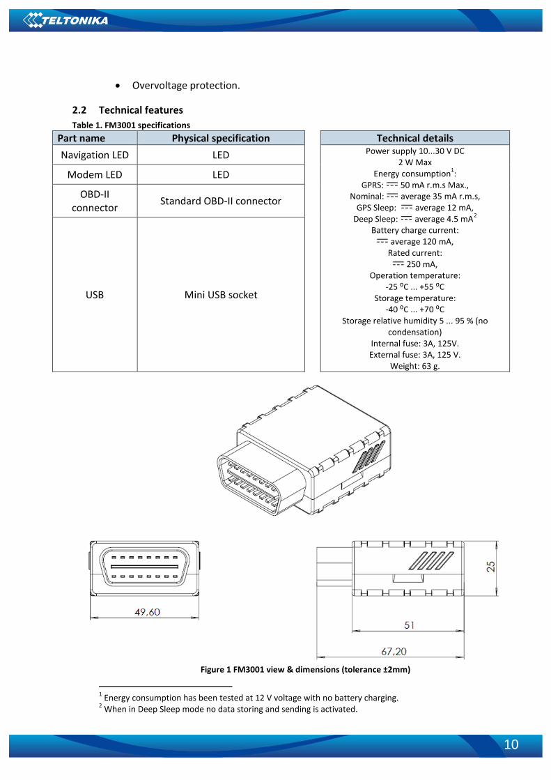
2.2 Technical features Table 1. FM3001 specifications
Part name Physical specification Technical details Navigation LED LED Power supply 10...30 V DC
2 W Max Energy consumption1:
GPRS: 50 mA r.m.s Max., Nominal: average 35 mA r.m.s,
GPS Sleep: average 12 mA, Deep Sleep: average 4.5 mA2
Battery charge current: average 120 mA, Rated current:
250 mA, Operation temperature:
-25 ⁰C ... +55 ⁰C Storage temperature:
-40 ⁰C ... +70 ⁰C Storage relative humidity 5 ... 95 % (no
condensation) Internal fuse: 3A, 125V. External fuse: 3A, 125 V.
Weight: 63 g.
Modem LED LED
OBD-II connector Standard OBD-II connector
USB Mini USB socket
Figure 1 FM3001 view & dimensions (tolerance ±2mm)
1 Energy consumption has been tested at 12 V voltage with no battery charging. 2 When in Deep Sleep mode no data storing and sending is activated.

11
2.3 Technical Information about internal battery Li-Polymer rechargeable battery, 3.7 V, 170 mAh.
Table 2 Battery specifications Internal back-up
battery Battery voltage V Nominal capacity (mAh) Power(Wh)
Charging temperature °C
Li-Polymer rechargeable
battery 3.75~3.90 ≥170 0.64 - 0.66 0 – 45
FM3001 internal battery is used for detecting external voltage disconnection.
CAUTION: RISK OF EXPLOSION IF BATTERY IS REPLACED BY AN INCORRECT TYPE. DISPOSE OF USED BATTERIES ACCORDING TO THE INSTRUCTIONS.
Battery Disposal instructions:
Battery should not be disposed of with general household waste. Bring damaged or worn-out batteries to your local recycling center or dispose them to battery recycle bin found in stores.
2.4 Electrical characteristics VALUE
CHARACTERISTIC DESCRIPTION
Min. Typ. Max. Unit
Supply Voltage: Supply Voltage (Recommended Operating Conditions) 10 30 V
2.5 Absolute Maximum Ratings VALUE
CHARACTERISTIC DESCRIPTION
Min. Typ. Max. Unit
Supply Voltage (Absolute Maximum Ratings) -30 30 V

12
3 CONNECTION, PINOUT, ACCESSORIES
3.1 How to insert micro SIM card into FM3001 device:
Remove FM3001 cover

13
Insert micro SIM card as shown
Make sure the SIM card is secure
Attach cover Device is ready
3.2 Installing FM3001 drivers Table 6. Software requirements:
Operating system (OS) Version MS .NET Framework version
Windows XP with SP3 or later
32 bit and 64 bit
MS .NET Framework 4 https://www.microsoft.com/en-US/Download/confirmation.aspx?id=17718 http://avl1.teltonika.lt/downloads/software/Framework/.NET%20Framework%204/dotNetFx40_Full_x86_x64.exe With MS .NET Framework 4 update KB2468871-v2 update

14
32 bit 64 bit
https://www.microsoft.com/en-us/download/details.aspx?id=3556 http://avl1.teltonika.lt/downloads/software/Framework/.NET%20Framework%204%20update%20KB2468871-v2/ NDP40-KB2468871-v2-x86.exe NDP40-KB2468871-v2-x64.exe or NDP40-KB2468871-v2-IA64.exe
Windows Vista Windows 7 Windows 8.1 Windows 10
32 bit and 64 bit
MS .NET Framework 4.6.2 https://www.microsoft.com/en-us/download/confirmation.aspx?id=53344
http://avl1.teltonika.lt/downloads/software/Framework/.NET%20Framework%204.6.2/NDP462-KB3151800-x86-x64-AllOS-ENU.exe
Drivers:
Please download COM Port drivers from Teltonika website: https://teltonika.lt/?media_dl=5543
Installing drivers:
Extract and run FP_INBOX_InstallDriver_v1.1032.3.exe. This driver is used to detect FM3001 device connected to the computer. Click 'Next' in driver installation window (figures below):
Figure 2 Driver installation window
This will launch device driver installation wizard. In the following window click ‘Install’
button:

15
Figure 3 Driver installation window
Setup will continue installing drivers and will display a window about successful process at
the end. Click 'Finish' to complete setup:
Figure 4 Driver installation window
You have now installed drivers for FM3001 device successfully.
3.3 OBD II
Figure 5 OBD II pinout

16
Pin No. Pin Name Description 1 PWM_BUS+/VPW 2 - 3 GND (-) Ground pin. 4 GND (-) Ground pin. 5 CAN_H 6 K-Line 7 - 8 - 9 PWM_BUS-
10 - 11 - 12 - 13 CAN_L 14 L-Line
15 Power +(10÷30) V DC
Power range +(10...30) V DC to ground
3.4 Navigate LED
3.5 Status LED Behavior Meaning
Blinking every second Normal mode Blinking every 2 seconds Deep sleep mode Blinking fast for a short time Modem activity Blinking fast constantly Boot mode Off • Device is not working
Or • Device firmware being flashed
4 OPERATIONAL BASICS
4.1 Operational principals FM3001 module is designed to acquire records and send them to the server. Records
contain GNSS data and I/O information. Module uses GNSS receiver to acquire GNSS data and is powered with three data acquiring methods: time-based, distance-based and angle-based. Note, that if FM3001 loses connection to GNSS satellites, it continues to make records, however coordinate in these records remains the same (last known coordinate). All data is stored in flash memory and later can be sent via GPRS.
Behavior Meaning Permanently switched on GNSS signal is not received Blinking every second Normal mode, GNSS is working Off GNSS is turned off because:
• Deep sleep mode Or
• GNSS antenna short circuited

17
GPRS and SMS settings are described in later sections. FM3001 communicates with server using special data protocol.
FM3001 can be managed by SMS commands. SMS Command list is described in SMS COMMAND LIST section. Module configuration can be performed only via SMS.
4.2 Sleep mode
4.2.1 Sleep mode FM3001 is able to go to sleep mode if such mode is enabled.
This timeout (defined period) starts counting when device is in STOP mode. After timeout is reached and all conditions for sleep mode are met, device goes to sleep mode. While in sleep mode, FM3001 turns GPS module off and it is still making new periodic records. As a result power usage decreases, in turn saving vehicle battery.
FM3001 can enter sleep mode if ALL of these conditions are met: • FM3001 has to be configured to work in Sleep mode and start sleep timeout is
reached; • Device must have synchronized time with GNSS satellites; • No movement by movement sensor is detected; • Ignition (configured Ignition Source) is off.
FM3001 exits sleep mode when if ONE of following conditions are true:
• Movement by movement sensor is detected; • Ignition (configured Ignition Source) is turned on.
4.2.2 Deep Sleep mode While in deep sleep mode, FM3001 sets GNSS receiver to sleep mode and turns off
3G/GSM/GPRS module (it is not possible to wake up device via SMS). Despite records with last known coordinate are being saved and send to AVL server (3G/GSM/GPRS module is turned on to send data and after that it is turned off again), power usage is decreased to save vehicle’s battery. Note, that power saving depends on two configurable parameters: send period and min. record saving period in “X on Stop Mode”.
FM3001 can enter deep sleep mode if ALL of these conditions are met: • FM3001 has to be configured to work in Deep Sleep mode; • Device must be synchronized time with GNSS satellites; • FM3001 has to be in „X on Stop Mode“ (Configured by Mode switch parameter); • Movement by accelerometer is not detected; • Ignition (Configured to be detected by Power Voltage, Ignition or Accelerometer) is
off; • Min. Record Saving Period (Data Acquisition Mode settings) must be bigger
than Active Data Link Timeout parameter, that FM3001 could close GPRS link. • Send period (Data Acquisition Mode settings) minus Active Data Link Timeout must
be more than 90 sec., that FM3001 could close GPRS link for at least 90 sec. • Sleep timeout is reached.
18
FM3001 exits deep sleep mode when if ONE of following conditions are true: • Movement by accelerometer is detected; Ignition (Configured to be detected by Power Voltage, Ignition or Accelerometer) is turned
on.
4.2.3 Online Deep Sleep mode In this mode device works as in Deep Sleep mode, but without turning off 3G/GSM
network. GSM part stays powered, so this increases power consumption. In this mode, device should received/send SMS and make/receive calls.
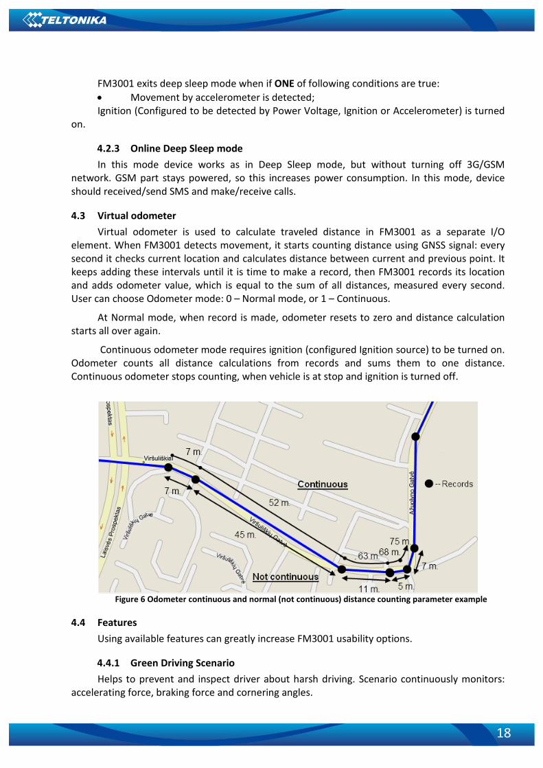
4.3 Virtual odometer Virtual odometer is used to calculate traveled distance in FM3001 as a separate I/O
element. When FM3001 detects movement, it starts counting distance using GNSS signal: every second it checks current location and calculates distance between current and previous point. It keeps adding these intervals until it is time to make a record, then FM3001 records its location and adds odometer value, which is equal to the sum of all distances, measured every second. User can choose Odometer mode: 0 – Normal mode, or 1 – Continuous.
At Normal mode, when record is made, odometer resets to zero and distance calculation starts all over again.
Continuous odometer mode requires ignition (configured Ignition source) to be turned on. Odometer counts all distance calculations from records and sums them to one distance. Continuous odometer stops counting, when vehicle is at stop and ignition is turned off.
Figure 6 Odometer continuous and normal (not continuous) distance counting parameter example
4.4 Features Using available features can greatly increase FM3001 usability options.
4.4.1 Green Driving Scenario Helps to prevent and inspect driver about harsh driving. Scenario continuously monitors:
accelerating force, braking force and cornering angles.

19
To prevent generating false events, harsh acceleration and harsh braking is monitored only when following conditions are fulfilled:
• Ignition is ON • Vehicle speed is equal or higher than 10 km/h
Harsh cornering is monitored only when following conditions are fulfilled: • Ignition is ON • Vehicle speed is equal or higher than 30 km/h
Note: Green Driving Scenario is a factor on various cars and various drivers testing phase and can be subject to changes. Teltonika is constantly working on improvement of the functionality of the devices, and strongly recommends using the latest version of the firmware.
4.4.2 Over Speeding Scenario. Helps to prevent from exceeding fixed speed and inspects driver if needed.
4.4.3 Excessive Idling Informs you if your vehicle is stationary but engine is on for selected period of time to help
you to save fuel
4.4.4 Jamming detection Jamming detection shows when GSM signal jamming occurs.
4.4.5 Trip Trip customizable feature enables user extended monitoring of performed trips (from
engine start at present location to engine stop at arrived location), log their start and stop points, view driven total distance3. Event will be generated (included into send records) only when trip starts and finishes.
Note: Scenarios and Trip feature are activated only if ignition is on.
4.5 Accelerometer scenarios
4.5.1 Towing Detection Towing detection scenario helps to inform driver about car deporting. FM3001 generates
event when car is being towed or raised, for example in case of vehicle evacuation.
3 Continuous odometer – total driven distance, works only in TRIP mode. Continues distance is counted only
for ONE trip. If trip is finnished (stop point is detected), odometer resets to 0 (zero). Next trip will start counting from the begining.

20
FM3001 activates towing function when these conditions are met: • Ignition (configured Ignition Source) is OFF • Activation Timeout (set in Towing detection features) is reached
When Activation Timeout is reached and Ignition is still in OFF state, FM3001 monitors accelerometer data. If Acceleration or Angle value reaches configured threshold for configured Duration (in ms), check Ignition state. If Ignition is still OFF during configured "Ignition check after Event Timeout" time, then event is generated. If configured - sends sms event or makes a call.
Function will be reactivated after FM3001 again detects change of Ignition state from ON to OFF.
4.5.2 Unplug Detection Unplug detection Scenario generates event when FM3001 is unplugged from OBD socket.
4.5.3 Crash Detection If Crash detection is enabled, it monitors acceleration on each axis, if acceleration exceeds
configured value for longer then configured duration, event with value “1” is generated.
4.5.3.1 Crash Trace operation If trace is enabled FM3001 will collect acceleration data every 40 msec.
4.5.3.2 blue-tooth blue-tooth can work in two modes - slave or master.
While working as master mode - blue-tooth can connect to defined "hands free" or "OBDII" system.
While working as slave mode - blue-tooth can accept incoming connection from external device.
5 CONFIGURATION New FM3001 module has default factory settings. Settings should be changed according to
your application and your 3G/GSM operator information.
It can be configured to acquire and send data to server. If device is not able to send data to server (e. g. GPRS connection is not available) FM3001 will start storing records to flash memory. It will send data later when GPRS is available again. Note that FM3001 can have memory full of records. In such case it will start deleting oldest records in order to save new ones. Please be aware that sending all data records to server may take some time.
FM3001 configuration may be performed via SMS commands or Configurator application, which will be introduced in this chapter. Contact sales manager to get the latest FM3001 Configurator version.
FM3001 Configurator operates on Microsoft Windows OS and uses MS .Net Framework 3.5 or higher. Please ensure that MS .Net Framework 3.5 or later is installed on your PC before starting configurator. Latest MS .Net Framework version can be downloaded from official Microsoft web page.

21
Module configuration can be performed over USB cable or blue-tooth connection. Configuration process starts from starting FM3001 Configurator program and then connecting to FM3001 device via Connect button located in the middle of home screen (see Figure 7). FM3001 has one user editable profile, which can be loaded from device, and saved. User can also revert to default settings, by pressing Reset to defaults button. After any modification of configuration settings, it has to be saved to FM3001 device, otherwise it will not be written to device.
Note: It is not recommended to downgrade firmware. We can‘t guarantee that all functions will be working correctly - it is possible that in old firmware versions there won‘t be some functions.
Figure 7 Configurator connection window
Connection window buttons description: ‘Create new configuration’ – opens offline configurator. ‘Connect to device’ (on the right, with connected device info) – connects to the device.

22
Figure 8 Configurator main window

23
Main Buttons description: ‘Load from device’ – loads the configuration from device. ‘Save to device’ – saves the configuration to device. ‘Load from file’ – loads the configuration from external file. ‘Save to file’ – saves the configuration to external file. ‘Update firmware’ – updates device firmware version. ‘Read records’ – reads records from external file. ‘Reset device’ – resets device. ‘Disconnect from device’ (with device info) – disconnects from device.
As it was mentioned, device can also be configured via SMS (GPRS) commands.
Keyword SMS (GPRS) commands:
"setkey <oldkeyword> <newkeyword>" - Set new or change the keyword. Configuration should be not locked. Example:
New keyword (set): <name>{space}<pass>{space}setkey{space}{space}{space}<newkeyword>
Change keyword (change): <name>{space}<pass>{space}setkey{space}<oldkeyword>{space}<newkeyword>
"delkey <keyword>" - Deletes current keyword. Configuration keyword should be configured and not locked.
Example: <name>{space}<pass>{space}setkey{space}<keyword>
Keyword configuration with TCP
Param ID 10 used for keyword configuration. Configuration should not be locked. Send empty if want delete the keyword, or not empty if want change/set
Param ID 10 config reading from SMS/GPRS forbidden.
More information on how to configure certain parameters via SMS (GPRS) commands will be introduced later in Chapter 6.

24
5.1 Status window
Figure 9. Status window
Status window shows main information about the connected device. It can be divided into
five main parts: 1. Device Info – shows general information about connected device e. g. Device Name,
Device IMEI, etc. 2. GNSS Info tab – shows GNSS information such as Modem Status, connected GNSS
satellite types, current coordinates, etc. 3. GSM Info – shows main information regarding 3G/GSM such as SIM State, GPRS
Status and so on. 4. I/O Info – shows information about the current status of various inputs and
outputs. 5. Maintenance – enables to receive current log file.

25
5.2 Security settings
Figure 10. Security settings window
The purpose of Security settings is to enable the user to set a keyword, which serves as a
protection, required if device will be connected to the Configurator again.
5.3 System settings System settings configurable parameters: 1. Sleep settings, where user can choose sleep mode; 2. Ignition source, where user can choose between power voltage and accelerometer
ignition sources 3. Object Motion Detection Settings, where user can configure 3 ways how FM3001 will
detect stopped movement, and change its working mode; 4. Static navigation settings, where user can turn static navigation on or off; 5. Records Settings, where user can enable or disable records when GPS is not available
(no time synchronization); 6. GNSS source Settings, where user can choose satellite system. 7. LED indication, where user can turn on or off indication LEDs. 8. Battery charge mode, where user can choose when battery charger is turned on.
Battery charge mode “On Need” - Enable battery charger any time when needed. “After Ignition ON” - Charger can be enabled after ignition is turned on, except if battery is fully charged or 10 minute timeout has not passed since device was turned on for faster FIX receiving.

26
9. Time synchronization mode, where you can choose how time synchronization is done. Possible values:
a) Disable (GPS only) – time is synchronized only from GNSS satellites b) NITZ – time is synchronized from GNSS satellites or GSM operator (not all GSM
operators support this functionality) c) NTP – time is synchronized from GNSS satellites or NTP servers. d) NITZ+NTP – time can be synchronized from GNSS satellites, GSM operator or NTP server
Figure 11 Time Synchronization settings
If necessary, you can configure your NTP servers and how often device should
resynchronize time from NTP (NTP Resync parameter).
Table 3 Configuration parameters Movement Source Vehicle on Stop mode Vehicle Moving mode
Ignition (recommended) If ignition is logic low If ignition is logic high
Movement (movement sensor)
Internal movement sensor does not detect movement
Internal movement sensor detects movement
GPS
GPS fix is available and vehicle speed is lower than 5 km/h
GPS fix is available and vehicle speed is higher than 5 km/h
While GPS fix is unavailable, Object Motion Detection Settings are working like in Msensor mode
CAN Speed Car CAN line does not produce a sufficient Speed value
Car CAN line produces a sufficient Speed value
Static Navigation Mode is a filter, which filters out track jumps when the object is
stationary. If Static navigation filter is disabled, it will apply no changes on GPS data. If Static navigation filter is enabled, it will filter changes in GPS position if no movement is detected (depends on Object Motion Detection Settings). It allows filtering GPS jumps when object is parked (is not moving) and GPS position is still traced.
27
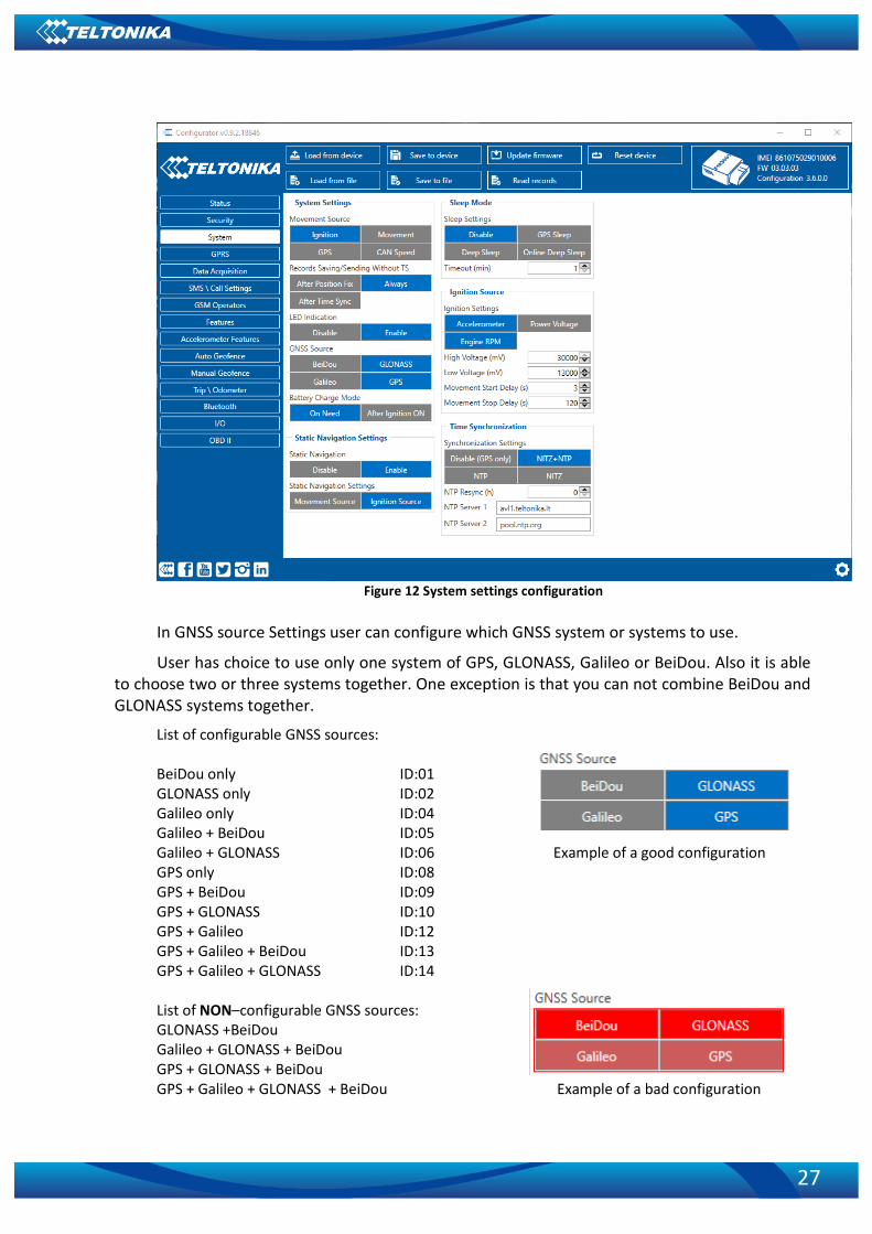
Figure 12 System settings configuration
In GNSS source Settings user can configure which GNSS system or systems to use.
User has choice to use only one system of GPS, GLONASS, Galileo or BeiDou. Also it is able to choose two or three systems together. One exception is that you can not combine BeiDou and GLONASS systems together.
List of configurable GNSS sources: BeiDou only ID:01 GLONASS only ID:02 Galileo only ID:04 Galileo + BeiDou ID:05 Galileo + GLONASS ID:06 Example of a good configuration GPS only ID:08 GPS + BeiDou ID:09 GPS + GLONASS ID:10 GPS + Galileo ID:12 GPS + Galileo + BeiDou ID:13 GPS + Galileo + GLONASS ID:14 List of NON–configurable GNSS sources: GLONASS +BeiDou Galileo + GLONASS + BeiDou GPS + GLONASS + BeiDou GPS + Galileo + GLONASS + BeiDou Example of a bad configuration

28
5.4 GPRS settings ‘GPRS’ defines main parameters for FM3001: GSM operator APN and GPRS username and
password (optional – depending on operator), destination server IP and port, and allows to set protocol used for data transfers – TCP or UDP.
Some operators use specific authentication for GPRS session – CHAP or PAP. If any of these is used, APN should be entered as ‘chap:<APN>’ or ‘pap:<APN>’. I.e. if operator is using APN ‘internet’ with CHAP authentication, it should be entered as ‘chap:internet’. Information about APN and authentication type should be provided by your GSM operator.
Backup Server settings enables the user to activate a backup server if Backup mode is selected and a parallel server if Duplicate option is selected.
Open Link Timeout is used to set timeout of link between FM3001 and AVL application termination. If FM3001 has already sent all records it waits for new records before closing link. If new records are generated in the period of this timeout, and minimum count to send is reached, they are sent to AVL application. This option is useful when GSM operator charge for link activation.
Server Response Timeout is used to set time period waiting for response from server side.
Also, here user can modify if FM3001 device will send newest records first, meaning, that the most important thing is to know recent position of car, older records are being sent right after newest records arrive to AVL application.
Figure 13 Records settings configuration

29
5.5 Data Acquisition settings Data Acquisition Modes are an essential part of FM3001 device, it is also highly
configurable.
By configuration user defines how records will be saved and sent. There are three different modes: Home, Roaming and Unknown. All these modes with configured data acquisition and send frequencies depend on current GSM Operator defined in Operator list (see section 0) and are switched when GSM operator changes (e.g. vehicle passes through country boarder).
If current GSM operator is defined as Home Operator, device will work in Home Data Acquisition mode, if current operator is defined as Roaming Operator, device will work in Roaming Data Acquisition mode, and if current operator code is not written in Operator list (but there is at least one operator code in the operator list), device will work in Unknown Acquisition mode.
This functionality allows having different AVL records acquire and send parameters values when object is moving or stands still. Vehicle moving or stop state is defined by Stop Detection Source parameter. There are 3 ways for FM3001 to switch between Vehicle on Stop and Vehicle Moving modes see section 5.7.
FM3001 has 6 different modes. Operational logic is shown in Figure 14.
If there are no operator codes entered into operator list, FM3001 will work in Unknown network mode ONLY.
Figure 14 Data Acquisition Mode configuration
30
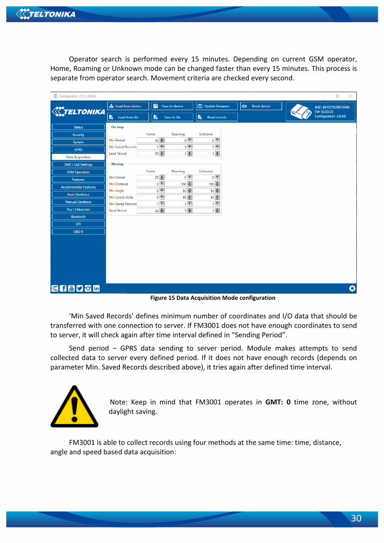
Operator search is performed every 15 minutes. Depending on current GSM operator, Home, Roaming or Unknown mode can be changed faster than every 15 minutes. This process is separate from operator search. Movement criteria are checked every second.
Figure 15 Data Acquisition Mode configuration
‘Min Saved Records’ defines minimum number of coordinates and I/O data that should be
transferred with one connection to server. If FM3001 does not have enough coordinates to send to server, it will check again after time interval defined in “Sending Period”.
Send period – GPRS data sending to server period. Module makes attempts to send collected data to server every defined period. If it does not have enough records (depends on parameter Min. Saved Records described above), it tries again after defined time interval.
Note: Keep in mind that FM3001 operates in GMT: 0 time zone, without daylight saving.
FM3001 is able to collect records using four methods at the same time: time, distance,
angle and speed based data acquisition:

31
Min. time period
Distance based data acquiring (Min. distance) – records are being acquired when the
distance between previous coordinate and current position is greater than defined parameter value. Entering zero disables data acquisition depending on distance.
Min. distance
Angle based data acquiring (Min. angle) – records are being acquired when angle
difference between last recorded coordinate and current position is greater than defined value. Entering zero disables data acquisition depending on angle.
Min. angle
Speed based data acquiring (Min. Speed Delta) – records are being acquired when speed
difference between last recorded coordinate and current position is greater than defined value. Entering zero disables data acquisition depending on speed.

32
5.6 SMS / Call Settings
Figure 16 SMS / Call settings window
Essential fields in ‘SMS’ part are ‘Login’ and ‘Password’. The login and password are used
with every SMS sent to FM3001. If login and password are not set, in every SMS sent to FM3001 device two spaces before command have to be used (<space><space><command>).
Command structure with set login and password:
<login><space><password><space><command>, example: “asd 123 getgps”
Phone numbers have to be written in international standard, without using “+” or “00” signs in prefix. This applies for Authorized Numbers and GSM Predefined Numbers lists. Authorized Numbers List holds numbers of the devices which are given permission to use commands (if no numbers are set, any number can use SMS commands). If no numbers are entered, configuration and sending commands over SMS are allowed from all GSM numbers. GSM Predefined Numbers holds the numbers which will be able to receive SMS messages generated by the I/O system.
The sent SMS messages format is according to: “Date Time EventText”
For example, if FM3001 is configured to send an SMS, when Ignition reaches High level, with priority High and configured to generate event on both, range enter and exit, then the sent SMS is:
“2012/6/7 12:00:00 Ignition 1”
33
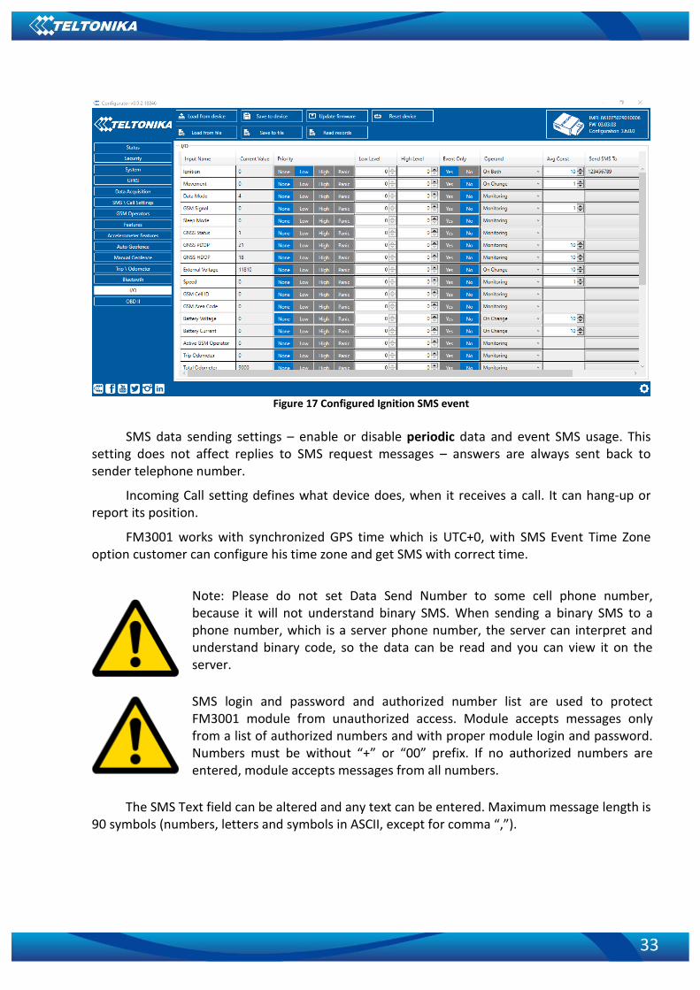
Figure 17 Configured Ignition SMS event
SMS data sending settings – enable or disable periodic data and event SMS usage. This setting does not affect replies to SMS request messages – answers are always sent back to sender telephone number.
Incoming Call setting defines what device does, when it receives a call. It can hang-up or report its position.
FM3001 works with synchronized GPS time which is UTC+0, with SMS Event Time Zone option customer can configure his time zone and get SMS with correct time.
Note: Please do not set Data Send Number to some cell phone number, because it will not understand binary SMS. When sending a binary SMS to a phone number, which is a server phone number, the server can interpret and understand binary code, so the data can be read and you can view it on the server.
SMS login and password and authorized number list are used to protect FM3001 module from unauthorized access. Module accepts messages only from a list of authorized numbers and with proper module login and password. Numbers must be without “+” or “00” prefix. If no authorized numbers are entered, module accepts messages from all numbers.
The SMS Text field can be altered and any text can be entered. Maximum message length is
90 symbols (numbers, letters and symbols in ASCII, except for comma “,”).

34
ATTENTION! If FM3001 is in Deep Sleep mode and SMS event occurs with LOW priority (which does not wake up FM3001), then the device does not send the message. It is saved in device memory until it wakes up from Deep Sleep mode and GSM modem starts working normally. After it wakes up, all the messages that are saved in memory will be sent, but keep in mind that only 10 messages can be saved in memory – all other messages will not be saved, until there is room in device memory.
5.7 GSM Operators list Operators list – FM3001 can work in different modes (use different settings) according to
the operator list defined. Operator list is used for Data Acquisition Mode switching Modes are changed based on GSM operator FM3001 is connected to.
Figure 18 Operator list configuration
If operator list is left empty, it will allow using GPRS to any GSM operator as Home
operator. Please note that FM3001 will work in Unknown mode only unless data sending is allowed – GPRS context is enabled.
5.8 Features settings In Features window four different scenarios are available.
35
Figure 19 Scenarios configuration
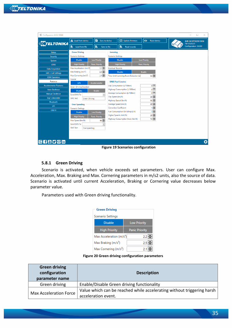
5.8.1 Green Driving Scenario is activated, when vehicle exceeds set parameters. User can configure Max.
Acceleration, Max. Braking and Max. Cornering parameters in m/s2 units, also the source of data. Scenario is activated until current Acceleration, Braking or Cornering value decreases below parameter value.
Parameters used with Green driving functionality.
Figure 20 Green driving configuration parameters
Green driving configuration
parameter name Description
Green driving Enable/Disable Green driving functionality
Max Acceleration Force Value which can be reached while accelerating without triggering harsh acceleration event.

36
Max Braking Force Value which can be reached while braking without triggering harsh braking event.
Max Cornering Force Value which can be reached while cornering without triggering harsh cornering event.
Green driving functionality generates events on three cases. If vehicles:
• Acceleration exceeds defined parameter value • Deceleration (braking) exceeds defined value • Cornering force exceeds defined value Program continously monitors and process data from accelerometer than decides whether harsh event is detected or not. If any of three cases are satisfied event is generated. Record is saved and sent to server (FM3001 must be configured properly). Event value is multiplied by 10 before sending/saving record to get more precision when displaying data*.
*Example. If acceleration harsh event of 3.55 m/s2 detected. Record with value 3.55*10 = 35.5 ≈ 36 will be saved ant sent to server.
Auto Calibaration 1. Vehicle stopped 2. Road is straight 3. Send SMS "auto_calibrate" 4. Acceleraate to > 30 km/h for 5 sec. 5. FM3001 will send response when calibration is success.
Calibration is saved to Internal Flash, after restart should be the same To check autocalibration status send: position_info To zero out accelerometer axis SMS: "calibrate", can be used, vehicle speed must be 0
km/h.
5.8.2 Over Speeding Scenario is activated, when vehicle speed exceeds parameter value. Scenario is activated
until current speed decreases below parameter value.
5.8.3 Jamming Scenario is activated (event sent to server), when jamming is detected.
5.8.4 GNSS Fuel Counter 1. To configure these parameters use fuel consumption data, which is stated in your car
technical documentation. By default speeds for this fuel consumption norms are: City – 30 km/h, Average – 60 km/h, Highway - 90 km/h. If you want, you can change it.
2. When speed is higher than highway speed, FM3001 adds highway fuel consumption x % of highway fuel consumption every y km/h, by default FM3001 adds 20% every 50 km/h. It means that fuel consumption is (1.2 * Highway Fuel Consumption) on 140 km/h speed, (1.4 * Highway Fuel Consumption) on 190 km/h speed.

37
3. Correction coefficient is used for correction of every fuel consumption value which is sent to server (Used Fuel * Correction coefficient). By default it is 1, min 0.01 and max 2. For example when correction coefficient is 1 and FM3001 calculates that used fuel for 35 m distance is 20 ml, sent value will be 20 ml; if correction coefficient is 1.2, sent value will be 20 * 1.2 = 24 ml.
Figure 20 GNSS Furl Counter configuration parameters
4. Fuel consumption on idling is used to calculate fuel consumption when ignition is on, but vehicle speed is 0 km/h. By default it is 1 l/h, min 0 and max 5 l/h. Almost in all diesel cars this parameter is less than 1.0 l/h. In gasoline cars this parameter is about 1.5 – 2.0 l/h.
5.9 Accelerometer features settings This window holds the settings which are highly related to accelerometer functionality.
Figure 21 Accelerometer features configuration parameters

38
5.9.1 Excessive Idling Scenario is activated, when vehicle stops for specific amount of time. You can configure
time it takes to turn on this scenario (Time to Stopped). Scenario is activated until vehicle starts moving and keeps moving for amount of time that is configured. You can configure time it takes to turn OFF this scenario (Time to Stopped).
5.9.2 Towing Detection FM3001 activates towing function when these conditions are met:
• Ignition (configured Ignition Source) is OFF • Activation Timeout (set in Towing detection features) is reached
When Activation Timeout is reached and Ignition is still in OFF state, FM3001 monitors
accelerometer data. If Acceleration or Angle value reaches configured threshold for configured Duration (in ms), check Ignition state. If Ignition is still OFF during configured "Ignition check after Event Timeout" time, then event is generated. If configured - sends SMS event message or makes a call. Function will be reactivated after FM3001 again detects change of Ignition state from ON to OFF.
Figure 22 Towing detection parameters
Activation timeout – Activation timeout is time after which FM3001 turns ON Towing
detection function if other requirement is met (Ignition OFF state detected). It is measured in minutes.
Ignition check after event – defines time period (in seconds) to check ignition state when Acceleration or Angle value reach. If towing event is generated during this time period, it is skipped. It allows to filter out redundant towing events while entering the car.
Make Call to – if function enabled makes call to specified phone number (configured in pre defined numbers)
Acceleration, Angle – values used to detect towing when ignition is OFF Duration – defines time period to check Acceleration, Angle values.

39
5.9.3 Crash Detection Crash Detection functionality can be set according to these settings: • Threshold (mg) • Duration (ms)
If accident happens and FM3001 detects acceleration value higher than set threshold value
during set time period, then device will generate an event. Threshold and duration values are set depending of accident power which you want to detect. FM3001 can detect a slight tapping on the device (Threshold = 100mg, Duration = 1ms) or can detect severe accident (Threshold = 4000mg,Duration = 5 ms).
Crash Trace operation If trace is enabled FM3001 will collect acceleration data every 40 msec. Buffer is big
enough to hold data for 5 seconds and on Crash Event detection, records will be generated from this buffer, following these conditions:
• Every second • Acceleration changed more then > 50mG
Data will be collected and records generated 5 seconds after the event using the same conditions.
Every generated record will have accelerometer X Y Z values included. Each record will have accurate timestamps in milliseconds (for detailed crash trace record structure refer to FM3001 protocol document).
Usually between 20 to 30 records is generated on crash event detection.
Figure 23 Example of Crash Trace logic
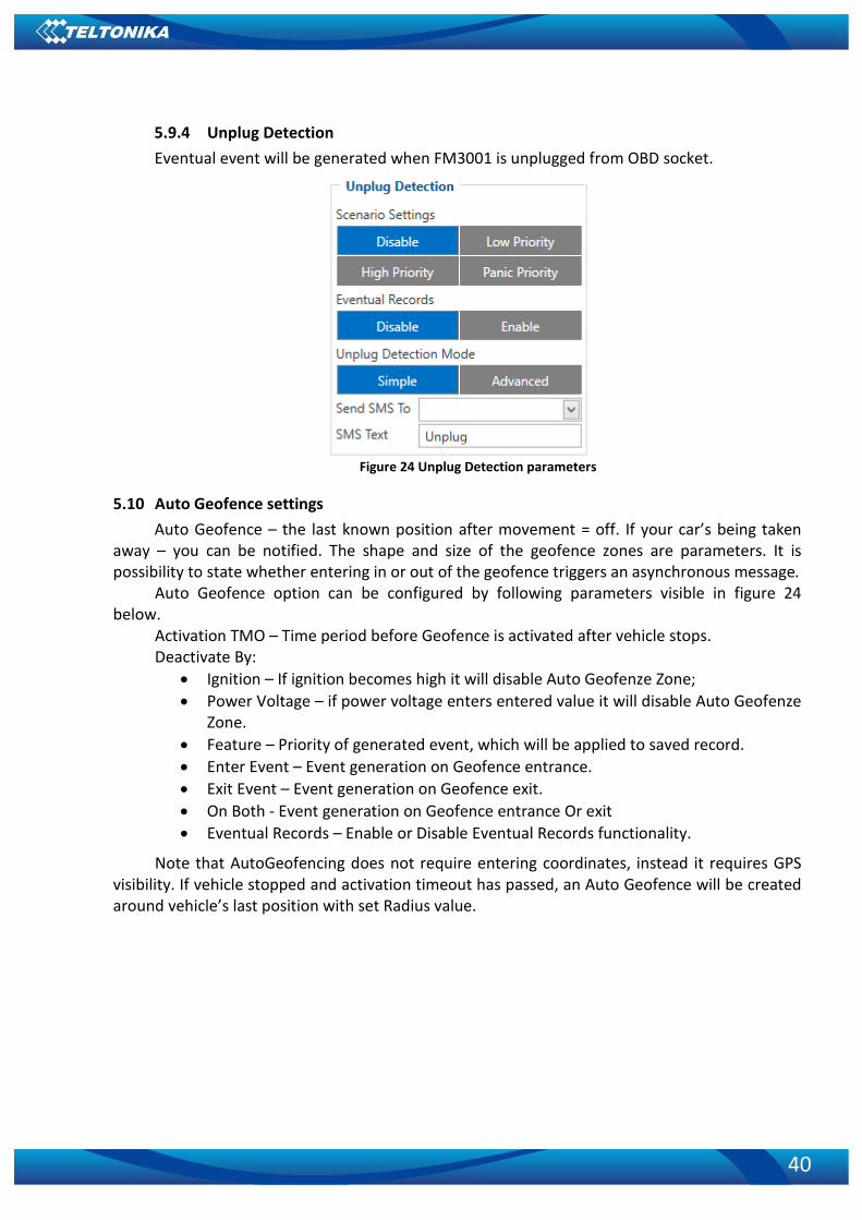
40
5.9.4 Unplug Detection Eventual event will be generated when FM3001 is unplugged from OBD socket.
Figure 24 Unplug Detection parameters
5.10 Auto Geofence settings Auto Geofence – the last known position after movement = off. If your car’s being taken
away – you can be notified. The shape and size of the geofence zones are parameters. It is possibility to state whether entering in or out of the geofence triggers an asynchronous message.
Auto Geofence option can be configured by following parameters visible in figure 24 below.
Activation TMO – Time period before Geofence is activated after vehicle stops. Deactivate By:
• Ignition – If ignition becomes high it will disable Auto Geofenze Zone; • Power Voltage – if power voltage enters entered value it will disable Auto Geofenze
Zone. • Feature – Priority of generated event, which will be applied to saved record. • Enter Event – Event generation on Geofence entrance. • Exit Event – Event generation on Geofence exit. • On Both - Event generation on Geofence entrance Or exit • Eventual Records – Enable or Disable Eventual Records functionality.
Note that AutoGeofencing does not require entering coordinates, instead it requires GPS visibility. If vehicle stopped and activation timeout has passed, an Auto Geofence will be created around vehicle’s last position with set Radius value.

41
Figure 25 Geofence configuration window
5.11 Manual Geofence FMB1YX has 50 configurable Geofence
zones and it can generate an event when defined Geofence zone border is crossed.
Frame border – frame border is an additional border around Geofence zone. It is additional area around defined zone used to prevent false event recording when object stops on the border of the area and because of GNSS errors some records are made inside area and some – outside. Event is generated only when both borders are crossed. See figure 35 for details: blue track is considered to have entered the area while red track is not.
Figure 26 Geofence border

42
Shape – can be rectangle or circle. User can choose what geozone shape will be. Priority – priority of Geofence event: low, high or panic. These levels define priority of
event information sending to server. See I/O element description for more details about priorities in I/O settings chapter.
Generate event (On entrance, On exit, On Both) – choose when record will be generated. Eventual records – when disabled scenario status value will be appeared in each AVL
record, and when enabled scenario status value will be appended only to eventual records. OverSpeeding – in each geozone OverSpeeding scenario can be configured separately.
Regular OverSpeeding functionality and geozones OverSpeeding funkctionality is working independently. If digital output control is enabled in regular OverSpeeding scenario, geozones OverSpeeding scenario controls it too. If device is in more that one geozone and OverSpeeding is detected in any zone then digital output turns on. Digital output turns off only when OverSpeeding is not detected anywhere (regular OverSpeeding and geozones OverSpeeding).
X1 – geofence zone left bottom corner X coordinate (longitude); Y1 – geofence zone left bottom corner Y coordinate (latitude); X2 or R – geofence zone upper right corner X coordinate (longitude) or radius of circle
when Circular zone is used (radius in meters); Y2 – geofence zone upper right corner Y coordinate (latitude).
Figure 27 Geofence configuration

43
5.12 Trip / Odometer settings Trip scenario offers user to configure Trip feature. Start Speed – GPS speed has to be greater than the specified Start Speed in order to detect
Trip Start. Ignition Off Timeout – timeout to wait if ignition was off, to detect Trip stop. Continuous distance counting – Not or Continuous can be chosen. For this feature I/O
Odometer must be enabled. If I/O Odometer is enabled and Continuous distance counting variable (Mode) is set to
Continuous, Trip distance is going to be counted continuously (from Trip start to Trip stop). This value is written to I/O Odometer value field. When Trip is over and next Trip begins, Odometer value is reset to zero. When the next trip starts counting continuously starts from the beginning again.
If I/O Odometer is enabled and Continuous Distance Counting variable (Mode) is set “Between Records”, then the distance is going to be counted only between every record made. This value is written to I/O Odometer value field and reset to zero every new record until Trip stops. If later all Odometer values are summed up manually, the user gets the distance driven during the whole period of the Trip.
Figure 26 Trip configuration
Advanced Trip Settings have an Eco Score Allowed Events which regulates the amount Eco
Score evnts allowed. Odometer calculates the distance travelled. Here user is able to select the source of
calculations and set a starting value.

44
Figure 27 Trip / Odometer settings
Figure 28 Trip continuous distance counting parameter example
5.13 blue-tooth settings

45
Figure 29 blue-tooth settings window

46
Figure 30 General blue-tooth settings
BT Radio determines state determines blue-tooth status, possible values: a) Disable – blue-tooth is off; b) Enable (hidden) – blue-tooth is on, device automatically connects to defined MAC, but
is invisible for external devices which want to pair with it. c) Enable (visible) – blue-tooth is on and visible for external devices.
Local name can be set according to your needs. If this field is empty, name will be automatically generated:
FM3001xx_<imei last chars> Local PIN - PIN code which will be used when external device will try to pair with FM3001. NOTE: FM3001 supports ONE connection at a time. Security mode possible options: a) PIN only – only pin is used when external device tries to connect to FM3001. b) PIN+MAC list – PIN is used, also external device’s MAC address needs to be in
Authorized MAC list c) MAC list only – connection to FM3001 is possible only if external device MAC is in
Authorized MAC list. d) None – no security enabled.
Figure 31 Auto connection to external devices

47
Here you can enter details of external blue-tooth headset for hands free communication. External MAC – MAC of your blue-tooth headset. External Name – blue-tooth name of you
Figure 32 MAC list
Figure 32 shows list of Authorized MAC addresses which are allowed to connect to
FM3001. If list is empty, any external device can connect to FM3001. blue-tooth Control section shows Discovered Devices and Paired Devices lists.
5.13.1 How to connect blue-tooth Hands Free adapter to FM3001 device blue-tooth settings configuration These are instructions how to easily prepare blue-tooth Hands Free device connection to
FM3001 device. First we need to configure FM3001 device blue-tooth settings for proper connection to this hands-free unit. These are required steps:
Figure 33 blue-tooth settings
1. When device configuration is loaded press „blue-tooth“ settings.
2. Turn on BT Radio by pressing „Enable (visible)“. You could leave “Local name” box empty (then device name will automatically be “FM3001xx_[last 7 IMEI digits]”) or type your own desirable name.

48
3. Set Security Mode to “PIN only” or “None”. You could select “PIN + MAC list” or “MAC list only” security mode but in this case you need to type external device MAC address in “Authorized Devices MAC List”.
4. Set connection mode to “Data Link”.
5. Set „External Name“ as your Hands Free device name for proper device identification and connection to it. In this example Hands Free headset name is „jabra“ but at least 2 characters are needed to recognize it and connect to it. For better and faster adapter identification in network you could enter a full device name. You could check your Hands Free adapter blue-tooth name by scanning nearby blue-tooth devices using mobile phone or computer with blue-tooth adapter.
Figure 34 Auto Connect settings
6. Go to “SMS / Call Settings” in left menu and set “Incomming Call Action” to “Do
Nothing” visible at Figure 34.
Figure 35. Incomming Call Action settings.
7. After all these steps press „Save to device“ to save configuration.
8. Now you can disconnect FM3001 device from a PC or stay connected if you want to make further changes to configuration.
Connecting blue-tooth Hands Free adapter After this configuration you could connect your Hands Free device to FM3001 device.
Turn on Hands Free device then turn on its blue-tooth connection for pairing following your model instructions4. Hands Free adapter should make a special sound in ear from speaker or its led identification should change to inform about successful connection5. To check if adapter is successfully connected, call to FM3001 device, Hands Free device should start ringing. If you later restart FM3001 device it will automatically connect to this adapter.
4 Hands Free device blue-tooth connection pairing instructions depends on specific model. 5 Hands Free device notification about paired blue-tooth connection depends on specific model.

49
5.13.2 Device’s log using your mobile phone. When FM3001 device starts, automatically blue-tooth is ON too. Turn on blue-tooth on your phone. Scan for nearby devices, find your device in list, distinguish device by last IMEI numbers on device module. Press pair, wait until device asks to enter pairing password, type: PIN (default PIN is 5555). Paired device will show up in Paired Devices list. From play/app store download a blue-tooth terminal (e. g. BlueTerm). Run the app, click find and connect to your device. Now we need to send command to FM3001 through blue-tooth terminal, type: .log:1
Device will respond Debug enabled and FM3001 log will show up. Do not forget to start save log file to mobile phone.
In order to pair FM3001 device with Android smartphone, make sure that BT radio is enabled (visible) in device configuration. It can be checked via SMS command too:
getparam 800
The answer has to be 2, which means “Enabled and visible”.
5.14 I/O settings When none of I/O elements are enabled, AVL packet comes with GNSS information only.
After enabling I/O element(s) AVL packet along with GNSS information contains current value(s) of enabled I/O element.
Enabled or disabled field – allows enabling I/O element so it is added to the data packet
and is sent to the server. By default all I/O element are disabled and FM3001 records only GNSS coordinates.
Priority (AVL packet priority) all records made by FM3001 are regular. Regular packets are sent as Low priority records. When low priority event is triggered, FM3001 makes additional record with indication that the reason for that was I/O element change.
Table 4 Permanent I/O elements
Permanent I/O elements (are always sent to server if enabled) Nr. Property Name Description 1 Ignition Logic: 0 / 1 2 Movement Logic: 0 / 1
3 Data mode 0 – home on stop, 1 – home on move, 2 – roaming on stop, 3 – roaming on move, 4 – unknown on stop, 5 – unknown on move
Note: Unfortunately it is not possible to do the same on iPhone, because there is no native SPP blue-tooth profile support in iPhone.

50
4 GSM signal GSM signal level value in scale 1 – 5 5 Sleep mode Logic: 0 / 1
6 GNSS Status
States: 0 – short circ., 1 – connected. Parameter defines if GPS antenna is short circuit. All the time value will be sent 1. The only condition to get value 0, then antenna is damaged and short circuit.
7 GNSS PDOP Probability * 10; 0-500 8 GNSS HDOP Probability * 10; 0-500 9 External Voltage Voltage: mV, 0 – 30 V 10 Speed Value in km/h, 0 – xxx km/h 11 GSM Cell ID GSM base station ID
12 GSM Area Code
Location Area code (LAC), it depends on GSM operator. It provides unique number which assigned to a set of base GSM stations. Max value: 65536
13 Battery Voltage Shows battery Voltage in mV 14 Battery Current Shows battery Current in mA 15 Active GSM operator Currently used GSM Operator code 16 Trip odometer Distance between two records: m 17 Total odometer Total odometer count: m 18 Fuel Used GPS Fuel used (ml) by GPS 19 Fuel Rate GPS Fuel Consumption by average speed (l/100km) 20 Axis X Accelerometer axis x value 21 Axis Y Accelerometer axis y value 22 Axis Z Accelerometer axis z value 23 ICCID SIM card identification number 24 Eco Score Eco Score evaluation 25 User ID User ID for eco score app 26 Network Type Current active network type
OBD II Parameters 27 Number Of DTC Diagnostic Trouble Codes 28 Engine Load Engine load percentage 29 Coolant Temperature Engine coolant temperature, ⁰C 30 Short Fuel Trim Change in fuel level over short time 31 Fuel Pressure Fuel pressure in tank 32 Intake MAP Intake manifold absolute pressure 33 Engine RPM Engine rotations per minute 34 Vehicle speed Vehicle speed 35 Timing advance Ignition timing advance 36 Intake air temperature Intake air temperature 37 MAF Mass air-flow meter data 38 Throttle position Throttle position percentage 39 Run time since engine start Run time since engine start 40 Distance traveled MIL on Distance traveled with “Malfunction Indicator
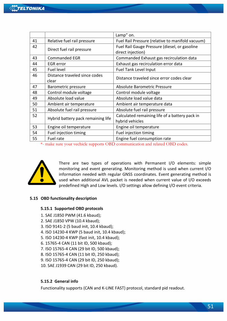
51
Lamp” on. 41 Relative fuel rail pressure Fuel Rail Pressure (relative to manifold vacuum) 42 Direct fuel rail pressure Fuel Rail Gauge Pressure (diesel, or gasoline
direct injection) 43 Commanded EGR Commanded Exhaust gas recirculation data 44 EGR error Exhaust gas recirculation error data 45 Fuel level Fuel Tank Level Input 46 Distance traveled since codes
clear Distance traveled since error codes clear
47 Barometric pressure Absolute Barometric Pressure 48 Control module voltage Control module voltage 49 Absolute load value Absolute load value data 50 Ambient air temperature Ambient air temperature data 51 Absolute fuel rail pressure Absolute fuel rail pressure 52 Hybrid battery pack remaining life Calculated remaining life of a battery pack in
hybrid vehicles 53 Engine oil temperature Engine oil temperature 54 Fuel injection timing Fuel injection timing 55 Fuel rate Engine fuel consumption rate
*- make sure your vechicle supports OBD communication and related OBD codes.
There are two types of operations with Permanent I/O elements: simple monitoring and event generating. Monitoring method is used when current I/O information needed with regular GNSS coordinates. Event generating method is used when additional AVL packet is needed when current value of I/O exceeds predefined High and Low levels. I/O settings allow defining I/O event criteria.
5.15 OBD functionality description
5.15.1 Supported OBD protocols 1. SAE J1850 PWM (41.6 kbaud); 2. SAE J1850 VPW (10.4 kbaud); 3. ISO 9141-2 (5 baud init, 10.4 kbaud); 4. ISO 14230-4 KWP (5 baud init, 10.4 kbaud); 5. ISO 14230-4 KWP (fast init, 10.4 kbaud); 6. 15765-4 CAN (11 bit ID, 500 kbaud); 7. ISO 15765-4 CAN (29 bit ID, 500 kbaud); 8. ISO 15765-4 CAN (11 bit ID, 250 kbaud); 9. ISO 15765-4 CAN (29 bit ID, 250 kbaud); 10. SAE J1939 CAN (29 bit ID, 250 kbaud).
5.15.2 General info Functionality supports (CAN and K-LINE FAST) protocol, standard pid readout.

52
5.15.3 Initialization Functionality initializes automatically, finds proper protocol and communicates using it.
5.15.4 Data Data is saved as I/O elements. OBD I/O elements must be enabled by configurator. All OBD
elements are configured in same logic as other I/O property elements.
5.15.5 ELD ELD (Electronic Logging Device) functionality allows to record commercial motor vehicle engine
driving hours. In North America the driving hours of commercial drivers (truck and bus drivers) are regulated by the set of rules known as the hours of service (HOS). This rule was implemented from December of 2017 in USA.
ELD monitors vehicle’s ECU (Engine Control Unit) to capture data of engine working hours, vehicle movement state, driven distance and VIN (if available). FM3001 has possibility to read these parameters from SAE J1939 protocols, combine them with GPS data (timestamp and coordinates) and transmit this information via blue-tooth 3.0.
ELD functionality starts periodical data transmission6 via blue-tooth 3.0 right after external blue-tooth device (tablet, laptop or smartphone with ELD application) has been connected if OBD Feature (parameter ID 40000) is set to ELD (Value 2) (table 6.14.1 OBD elements pamateres and types).
ELD data sending is paused if Configurator is connected via blue-tooth and is resumed after configurator disconnects.
ELD data sending resumes automatically when external BT device reconnects after connection loss.
6 For detailed protocols please contact your sales manager.

53
6 SMS COMMAND LIST
6.1 Basic commands Commands are case sensitive. While FM3001 operates in Sleep mode and user tries to
send SMS message it will arrive to FM3001 device, because GSM module is enabled. Table 5 SMS commands list
Command Description Response getinfo Returns RTC time, GPS status, SAT Yes getver Returns code version, device IMEI, modem app version, RTC time Yes
getstatus Returns Data Link:0 GPRS:0 Phone:0 SIM:0 OP:24602 Signal:5 NewSMS:0 Roaming:0 SMSFull:0 LAC:0 Cell ID: 0
Yes
getgps Returns GPS status, Satellite number, Latitude, Longitude, Altitude, Speed, Date, Time
Yes
ggps Returns location information with Google maps link Yes readio Returns IO status Yes
cpureset Resets device No getparam Returns selected parameter value Yes setparam Sets selected parameter value Yes
flush Redirects device to other server Yes countrecs Returns record number Yes fc_reset Resets fuel consumption parameters Yes
towingreact Towing reactivation Yes btgetlist Returns requested blue-tooth list (values: 0, 1, 2) Yes btgscan Starts blue-tooth scan (values: none, 1) Yes btvisible Sets blue-tooth to visible with TMO Yes btrelease Disconnects from current device and pauses auto connect functionality for
TMO Yes
btunpair Unpair blue-tooth device Yes faultcodes Fault codes reading from OBD Yes
obdinfo Returns OBD info. Protocol, VIN, AdaptiveTiming value, requested PID counter, OBD application state, available vehicle PIDs, mil status, number of DTCs
Yes
cleardtc Clears a dtc counter and deletes fault codes Yes “setparam” SMS is used to configure device. Parameter ID consists of 3 or 5 digits. Detailed list of parameters and IDs can be found in
chapter number 5.2 “System parameters” Example: “username password setparam 102:0” will disable sleep mode. Multiple value setting in one sms: Example: “username password setparam 2001:wap;2002:user;2003:pass” will change
configured APN name, APN username and APN password. SMS command of limited to 160 characters.
6.1.1.1 getinfo Response details Description RTC RTC Time GPS GPS receiver state. 0 – OFF, 1 – restarting, 2 – ON but no fix, 3 –ON and
operational, 4 – sleep mode SAT Average satellites

54
Example: RTC:2017/1/9 14:13 GPS:1 SAT:0
6.1.1.2 getver Response details Description App Ver Firmware version Modem Ver Version of modem application GPS Ver Version of GPS module Hw Ver Version of hardware Device IMEI IMEI
Example: App Ver:01.00.17 Rev:01 Modem Ver:TM25Q_D_01.00.00.00_010 GPS Ver:AXN_3.82_3333_1Hw Ver:FM30010_MOD2_A0:B0:C1:D0 Device IMEI:352094080000950
6.1.1.3 getstatus Response details Description Data Link Indicate module connection to server at the moment: 0 – Not connected, 1
– connected GPRS Indicate if GPRS is available at the moment Phone Voice Call status: 0 – ready, 1 – unavailable, 2 – unknown, 3 –ringing, 4 –
call in progress, 5 – asleep SIM SIM Status: 0-ready, 1-pin, 2-puk, 3-pin2, 4-puk2 OP Connected to GSM Operator: numerical id of operator Signal GSM Signal Quality [0-5] NewSMS Indicate if new message received Roaming 0 – Home Network, 1 – roaming SMSFull SMS storage is full? 0 – ok, 1 – SMS storage full LAC GSM Tower Location Area Code Cell ID GSM Tower Cell ID Code
Example: Data Link: 0 GPRS: 1 Phone: 0 SIM: 0 OP: 24602 Signal: 5 NewSMS: 0 Roaming: 0 SMSFull: 0 LAC: 1 Cell ID: 3055
6.1.1.4 getgps Response details Description GPS Indicates valid (1) or invalid (0) Gps data Sat Count of currently available satellites Lat Latitude (Last good Latitude) Long Longitude (Last good Longitude) Alt Altitude Speed Ground speed, km/h Dir Ground direction, degrees Date Current date Time Current GMT time
Example: GPS:1 Sat:0 Lat:54.666042 Long:25.225031 Alt:0 Speed:0 Dir:0 Date: 17/1/9 Time: 12:52:30

55
6.1.1.5 ggps Response details Description D Date T Time S Actual Speed C Latitude (Last good Latitude), Longitude (Last good Longitude) Url Google Maps Link
Example: D:17/1/9 T:12:52:30 S:0.00 C:54.666042, 25.225032 Url: http://maps.google.com/?q=54.666042,25.225032&om=1speed:0
6.1.1.6 readio # Response details Description ID I/O element ID Value I/O Element value
Example: Param ID:3 Value:0
6.1.1.7 getparam Read parameter value. ID consists of 3 or 4 digits. Detailed list of parameters and IDs can
be found in chapter number 8 “Parameter List”
Example: “getparam 2001” command will request APN name
Answer: Param ID:2001 Value:wap
6.1.1.8 setparam Sets new value for parameter. ID consists of 3 or 4 digits. Detailed list of parameters and
IDs can be found in chapter number 8 “Parameter List”
Example: “setparam 2001:wap2” will change configured APN name
Answer: Param ID:2001 Value:wap2
6.1.1.9 flush #,#,#,#,#,#,# Initiates all data sending by GPRS to specified target server. Comma separated parameters
go as numbered:
1. # - IMEI 2. # - APN 3. # - GPRS LOGIN 4. # - GPRS PASSWORD 5. # - IP 6. # - PORT 7. # - MODE (0-TCP/1-UDP)
Parameters are separated by comma (no spaces needed). In case you don’t need to enter parameter (Login/Pass) – do not put space, simply put comma and write next parameter.
Example: opa opa flush 353976012555151,banga,,,212.47.99.62,12050,0
Response details Description FLUSH SMS Accepted FLUSH SMS Accepted # records found on FLASH Number of records found on FLASH
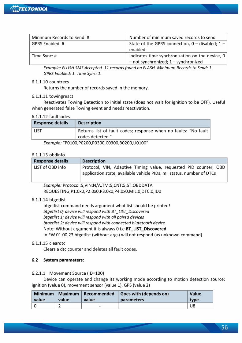
56
Minimum Records to Send: # Number of minimum saved records to send GPRS Enabled: # State of the GPRS connection, 0 – disabled; 1 –
enabled Time Sync: # Indicates time synchronization on the device, 0
– not synchronized; 1 – synchronized Example: FLUSH SMS Accepted. 11 records found on FLASH. Minimum Records to Send: 1. GPRS Enabled: 1. Time Sync: 1.
6.1.1.10 countrecs Returns the number of records saved in the memory.
6.1.1.11 towingreact Reactivates Towing Detection to initial state (does not wait for ignition to be OFF). Useful
when generated false Towing event and needs reactivation.
6.1.1.12 faultcodes Response details Description
LIST Returns list of fault codes; response when no faults: “No fault codes detected.”
Example: “P0100,P0200,P0300,C0300,B0200,U0100”.
6.1.1.13 obdinfo Response details Description LIST of OBD info Protocol, VIN, Adaptive Timing value, requested PID counter, OBD
application state, available vehicle PIDs, mil status, number of DTCs
Example: Protocol:5,VIN:N/A,TM:5,CNT:5,ST:OBDDATA REQUESTING,P1:0x0,P2:0x0,P3:0x0,P4:0x0,MIL:0,DTC:0,ID0
6.1.1.14 btgetlist btgetlist command needs argument what list should be printed! btgetlist 0; device will respond with BT_LIST_Discovered btgetlist 1; device will respond with all paired devices btgetlist 2; device will respond with connected blutetooth device Note: Without argument it is always 0 i.e BT_LIST_Discovered In FW 01.00.23 btgetlist (without args) will not respond (as unknown command).
6.1.1.15 cleardtc Clears a dtc counter and deletes all fault codes.
6.2 System parameters:
6.2.1.1 Movement Source (ID=100) Device can operate and change its working mode according to motion detection source:
ignition (value 0), movement sensor (value 1), GPS (value 2)
Minimum value
Maximum value
Recommended value
Goes with (depends on) parameters
Value type
0 2 - U8

57
6.2.1.2 Records Saving/Sending Without TS (ID=107)
When this feature is enabled (value = 1), then records can be saved and sent to server without time synchronization. Minimum value
Maximum value
Recommended value
Goes with (depends on) parameters
Value type
0 1 1 U8
6.2.1.3 Led Indication (ID=108) Sets led indication: 0 – disabled, 1 – enabled
Minimum value
Maximum value
Recommended value
Goes with (depends on) parameters
Value type
0 1 1 U8
6.2.1.4 GNSS Source (ID=109) This parameter sets Satellite System, available values: BeiDou only value: 1 GLONASS only value: 2 Galileo only value: 4 Galileo + BeiDou value: 5 Galileo + GLONASS value: 6 GPS only value: 8 GPS + BeiDou value: 9 GPS + GLONASS value: 10 GPS + Galileo value: 12 GPS + Galileo + BeiDou value: 13 GPS + Galileo + GLONASS value: 14
Minimum value
Maximum value
Recommended value
Goes with (depends on) parameters
Value type
0 14 - U8
6.2.1.5 Battery Charge Mode (ID=110) Sets battery charge mode: 0 – on need, 1 – After ignition ON.
Minimum value
Maximum value
Default value Goes with (depends on) parameters
Value type
0 1 0 U8 6.2.1.6 Static Navigation (ID=106)
When static navigation is enabled, FM3001 filters out GPS jumps, when it is not moving. When it is disabled, it does not make any changes to collected GPS data.
Minimum value
Maximum value
Recommended value
Goes with (depends on) parameters
Value type
0 1 1 U8
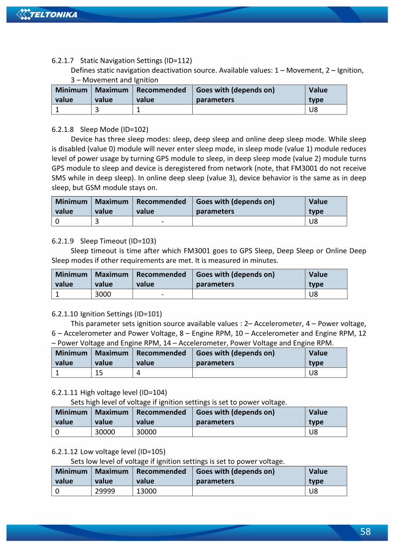
58
6.2.1.7 Static Navigation Settings (ID=112) Defines static navigation deactivation source. Available values: 1 – Movement, 2 – Ignition, 3 – Movement and Ignition
Minimum value
Maximum value
Recommended value
Goes with (depends on) parameters
Value type
1 3 1 U8
6.2.1.8 Sleep Mode (ID=102) Device has three sleep modes: sleep, deep sleep and online deep sleep mode. While sleep
is disabled (value 0) module will never enter sleep mode, in sleep mode (value 1) module reduces level of power usage by turning GPS module to sleep, in deep sleep mode (value 2) module turns GPS module to sleep and device is deregistered from network (note, that FM3001 do not receive SMS while in deep sleep). In online deep sleep (value 3), device behavior is the same as in deep sleep, but GSM module stays on.
Minimum value
Maximum value
Recommended value
Goes with (depends on) parameters
Value type
0 3 - U8
6.2.1.9 Sleep Timeout (ID=103) Sleep timeout is time after which FM3001 goes to GPS Sleep, Deep Sleep or Online Deep
Sleep modes if other requirements are met. It is measured in minutes.
Minimum value
Maximum value
Recommended value
Goes with (depends on) parameters
Value type
1 3000 - U8 6.2.1.10 Ignition Settings (ID=101)
This parameter sets ignition source available values : 2– Accelerometer, 4 – Power voltage, 6 – Accelerometer and Power Voltage, 8 – Engine RPM, 10 – Accelerometer and Engine RPM, 12 – Power Voltage and Engine RPM, 14 – Accelerometer, Power Voltage and Engine RPM. Minimum value
Maximum value
Recommended value
Goes with (depends on) parameters
Value type
1 15 4 U8
6.2.1.11 High voltage level (ID=104) Sets high level of voltage if ignition settings is set to power voltage.
Minimum value
Maximum value
Recommended value
Goes with (depends on) parameters
Value type
0 30000 30000 U8
6.2.1.12 Low voltage level (ID=105) Sets low level of voltage if ignition settings is set to power voltage.
Minimum value
Maximum value
Recommended value
Goes with (depends on) parameters
Value type
0 29999 13000 U8

59
6.2.1.13 Movement start delay (ID=19001) Sets the delay of movement detection after movement is made.
Minimum value
Maximum value
Recommended value
Goes with (depends on) parameters
Value type
1 60 1 U8
6.2.1.14 Movement stop delay (ID=19002) Sets the delay of stop detection when movement is stopped.
Minimum value
Maximum value
Recommended value
Goes with (depends on) parameters
Value type
5 300 60 U8 6.2.1.15 Time Synchronization (ID=900)
Sets the time synchronization source. 0 – Disable (GPS only), 1 – NITZ+NTP, 2 – NTP, 3 – NITZ. Minimum value
Maximum value
Recommended value
Goes with (depends on) parameters
Value type
0 3 1 U8
6.2.1.16 NTP Resync (ID=901) Sets NTP resynchronization time.
Minimum value
Maximum value
Recommended value
Goes with (depends on) parameters
Value type
0 24 24 U8
6.2.1.17 NTP Server 1 (ID=902) Sets the IP of the first NTP server.
Minimum value
Maximum value
Recommended value
Goes with (depends on) parameters
Value type
- - avl1.teltonika.lt U8
6.2.1.18 NTP Server 2 (ID=903) Sets the IP of the second NTP server.
Minimum value
Maximum value
Recommended value
Goes with (depends on) parameters
Value type
- - pool.ntp.org U8
6.3 GPRS parameters 6.3.1.1 GPRS Context (ID=2000)
Parameter allows or does not allow GPRS usage. If GPRS is not allowed value is 0, if GPRS is allowed value is 1. Minimum value
Maximum value
Recommended value
Goes with (depends on) parameters
Value type
0 1 APN Name (ID=2001) APN Username (ID=2002) APN Password (ID=2003)
S8

60
6.3.1.2 APN (ID=2001) Parameter defines GPRS Access Point Name.
Minimum value
Maximum value
Recommended value
Goes with (depends on) parameters
Value type
Empty 32 char string
GPRS Context (ID=2000) APN Username (ID=2002) APN Password (ID=2003)
S8[32]
6.3.1.3 APN Username (ID=2002) Parameter defines APN username. In case operator does not use username for login, value
should be empty. Minimum value
Maximum value
Recommended value
Goes with (depends on) parameters
Value type
Empty 30 char string
GPRS Context (ID=2000) APN Name (ID=2001) APN Password (ID=2003)
S8[30]
6.3.1.4 APN Password (ID=2003) Parameter defines APN password. In case operator does not use password for login, value
should be empty. Minimum value
Maximum value
Recommended value
Goes with (depends on) parameters
Value type
Empty 30 char string
GPRS Context (ID=2000) APN Name (ID=2001) APN Username (ID=2002)
S8[30]
6.3.1.5 Domain (ID=2004)
Parameter defines AVL data destination server IP address. Example: 212.47.99.62 Minimum value
Maximum value
Recommended value
Goes with (depends on) parameters
Value type
0 54 char string GPRS Context (ID=2000) S8[16]
6.3.1.6 Target Server Port (ID=2005) Parameter defines AVL data destination server port number. Example: 12050
Minimum value
Maximum value
Recommended value
Goes with (depends on) parameters
Value type
Empty 65535 GPRS Context (ID=2000) U16

61
6.3.1.7 Protocol (ID=2006) Parameter defines GPRS data transport protocol. Module can use TCP or UDP transport
protocol to send data to server. For TCP protocol value is 0, for UDP protocol value is 1. Minimum value
Maximum value
Recommended value
Goes with (depends on) parameters
Value type
0 1 GPRS Context (ID=2000) U8
6.3.1.8 Backup Server Mode (ID=2010) Sets backup server mode: 0 – Disable, 1 – Backup, 2 – Duplicate.
Minimum value
Maximum value
Recommended value
Goes with (depends on) parameters
Value type
0 2 Backup Server Domain (ID=2007) Backup Server Port (ID=2008) Backup Server Protocolo (ID=2009)
S8[30]
6.3.1.9 Backup Server Domain (ID=2008) Parameter defines backup server IP address. Example: 212.47.99.62
Minimum value
Maximum value
Recommended value
Goes with (depends on) parameters
Value type
0 54 char string
Backup Server Mode (ID=2010) Backup Server Port (ID=2008) Backup Server Protocolo (ID=2009)
S8[16]
6.3.1.10 Backup Server Port (ID=2008)
Parameter defines AVL data destination server port number. Example: 12050 Minimum value
Maximum value
Recommended value
Goes with (depends on) parameters
Value type
Empty 65535 Backup Server Domain (ID=2007) Backup Server Mode (ID=2010) Backup Server Protocolo (ID=2009)
U16
6.3.1.11 Protocol (ID=2009) Parameter defines GPRS data transport protocol. Module can use TCP or UDP transport
protocol to send data to server. For TCP protocol value is 0, for UDP protocol value is 1. Minimum value
Maximum value
Recommended value
Goes with (depends on) parameters
Value type
0 65535 Backup Server Domain (ID=2007) Backup Server Port (ID=2008) Backup Server Mode (ID=2010)
U8

62
6.3.1.12 Open Link Timeout (ID=1000) Defines for how many seconds device will keep connection to the server after successful
data transfer while waiting for a new record. Minimum value
Maximum value
Recommended value
Goes with (depends on) parameters
Value type
30 259200 U32
6.3.1.13 Response Timeout (ID=1001) Defines time period in seconds for server response to send records.
Minimum value
Maximum value
Recommended value
Goes with (depends on) parameters
Value type
5 300 U32
6.3.1.14 Sort By (ID=1002) Record sorting parameter is responsible for record sorting order. Value of 0 arranging data
starting from newest, while value of 1 arranging data starting from oldest. Minimum value
Maximum value
Recommended value
Goes with (depends on) parameters
Value type
0 1 U8 ATTENTION! Some GSM operators may disconnect the device from an
active data link if the device doesn’t send any data for a very long time, even if active data link timeout is set to maximum value. The amount of time that an operator keeps the link open depends solely on the operator. For example, if active data link timeout is set to maximum, 259200 seconds (72 hours), and the device sends data to server every 86400 seconds (24 hours), the operator might disconnect the link earlier and the device will have to connect to the server anew. This may cost extra, depending on the operator GPRS data charge. It is strongly recommended, when using active data link timeout, that data sending to the server should not be very rare (24 hours or more). If data sending is more frequent, then the operator will not disconnect the device form the server.
6.3.1.15 FOTA WEB Settings: Status (ID=13003)
Defines FOTA Web status: 0 – Disable, 1 – Enable. Minimum value
Maximum value
Recommended value
Goes with (depends on) parameters
Value type
0 1 Domain (ID=13000) Port (ID=13001) Period (ID=13002)
U8
6.3.1.16 FOTA WEB Settings: Domain (ID=13000)
Sets FOTA Web domain. Minimum value
Maximum value
Recommended value
Goes with (depends on) parameters
Value type
Empty 54 char string Status (ID=13003) Port (ID=13001) Period (ID=13002)
U32

63
6.3.1.17 FOTA WEB Settings: Port (ID=13001)
Sets FOTA Web port. Minimum value
Maximum value
Recommended value
Goes with (depends on) parameters
Value type
0 65535 Status (ID=13003) Domain (ID=13000) Period (ID=13002)
U32
6.3.1.18 FOTA WEB Settings: Period (ID=13002)
Record sorting parameter is responsible for record sorting order. Value of 0 arranging data starting from newest, while value of 1 arranging data starting from oldest. Minimum value
Maximum value
Recommended value
Goes with (depends on) parameters
Value type
30 65535 Status (ID=13003) Domain (ID=13000) Port (ID=13001)
U8
6.4 Data Acquisition settings
6.4.1 Home Network GSM operator code “On stop” parameters
6.4.1.1 Min Period (ID=10000) This parameter indicates time interval in seconds in order to acquire new record. If value is
0 it means no records by min period will be saved. Minimum value
Maximum value
Recommended value
Goes with (depends on) parameters
Value type
0 2592000 U32
6.4.1.2 Min Saved Records (ID=10004) This parameter defines minimum number of records in one data packet that can be sent to
server. It has higher priority than Data Send Period (ID=10005). Minimum value
Maximum value
Recommended value
Goes with (depends on) parameters
Value type
1 255 1 U8
6.4.1.3 Send Period (ID=10005) This parameter indicates frequency (time interval in seconds) of sending data to server.
Minimum value
Maximum value
Recommended value
Goes with (depends on) parameters
Value type
0 2592000 Min Saved Records (ID=10004) U32

64
6.4.2 Home Network GSM operator code “Moving” parameters 6.4.2.1 Min Period (ID=10050)
This parameter indicates time interval in seconds in order to acquire new record. If value is 0 it means no records by min period will be saved. Minimum value
Maximum value
Recommended value
Goes with (depends on) parameters
Value type
0 2592000 Min Distance (ID=10051) Min Angle (ID=10052) U32
6.4.2.2 Min Distance (ID=10051)
This parameter indicates distance in meters in order to acquire new record. Record is stored when the distance between previous records is greater than parameters value. If value is 0 it means no records by min distance will be saved. Minimum value
Maximum value
Recommended value
Goes with (depends on) parameters
Value type
0 65535 Min Period (ID=10050) Min Angle (ID=10052) U32
6.4.2.3 Min Angle (ID=10052)
This parameter indicates angle in degrees in order to acquire new record. If angle difference between last recorded coordinate and current position is greater than defined value, new record is stored. This parameter is operational, when speed is higher than 10 km/h. If value is 0 it means no records by min angle will be saved. Minimum value
Maximum value
Recommended value
Goes with (depends on) parameters
Value type
0 180 Min Period (ID=10050) Min Distance (ID=10051) U16
6.4.2.4 Min Speed delta (ID=10053)
This parameter indicates speed difference in order to acquire new record. If speed difference between last recorded coordinate and current position is greater than defined value, new record is stored. If value is 0 it means no records by min distance will be saved. Minimum value
Maximum value
Recommended value
Goes with (depends on) parameters
Value type
0 255 10 Min Period (ID=10050) Min Distance (ID=10051) Min Angle (ID=10052)
U16
6.4.2.5 Min Saved Records (ID=10054)
This parameter defines minimum number of records in one data packet that can be sent to server. It has higher priority than Data Send Period (ID=10055). Minimum value
Maximum value
Recommended value
Goes with (depends on) parameters
Value type
1 255 1 Min Period (ID=10050) Min Distance (ID=10051) Min Angle (ID=10052)
U8

65
6.4.2.6 Send Period (ID=10055)
This parameter indicates frequency (time interval in seconds) of sending data to server. Minimum value
Maximum value
Recommended value
Goes with (depends on) parameters
Value type
0 2592000 U32
6.4.3 Roaming Network GSM operator code “On stops” parameters 6.4.3.1 Min Period (ID=10100)
This parameter indicates time interval in seconds in order to acquire new record. If value is 0 it means no records by min period will be saved. Minimum value
Maximum value
Recommended value
Goes with (depends on) parameters
Value type
0 2592000 U32
6.4.3.2 Min Saved Records (ID=10104) This parameter defines minimum number of records in one data packet that can be sent to
server. It has higher priority than Data Send Period (ID=10105). Minimum value
Maximum value
Recommended value
Goes with (depends on) parameters
Value type
1 255 1 U8
6.4.3.3 Send Period (ID=10105) This parameter indicates frequency (time interval in seconds) of sending data to server.
Minimum value
Maximum value
Recommended value
Goes with (depends on) parameters
Value type
0 2592000 Min Saved Records (ID=10104) U32
6.4.4 Roaming Network GSM operator code “Moving” parameters 6.4.4.1 Min Period (ID=10150)
This parameter indicates time interval in seconds in order to acquire new record. If value is 0 it means no records by min period will be saved. Minimum value
Maximum value
Recommended value
Goes with (depends on) parameters
Value type
0 2592000 Min Distance (ID=10151) Min Angle (ID=10152) U32
6.4.4.2 Min Distance (ID=10151)
This parameter indicates distance in meters in order to acquire new record. Record is stored when the distance between previous records is greater than parameter’s value. If value is 0 it means no records by min distance will be saved. Minimum value
Maximum value
Recommended value
Goes with (depends on) parameters
Value type
0 65535 Min Period (ID=10150) Min Angle (ID=10152) U32

66
6.4.4.3 Min Angle (ID=10152)
This parameter indicates angle in degrees in order to acquire new record. If angle difference between last recorded coordinate and current position is greater than defined value, new record is stored. This parameter is operational, when speed is higher than 10km/h. If value is 0 it means no records by min angle will be saved. Minimum value
Maximum value
Recommended value
Goes with (depends on) parameters
Value type
0 180 Min Period (ID=10150) U16
6.4.4.4 Min Speed (ID=10153) This parameter indicates speed difference in order to acquire new record. If speed
difference between last recorded coordinate and current position is greater than defined value, new record is stored. If value is 0 it means no records by min distance will be saved. Minimum value
Maximum value
Recommended value
Goes with (depends on) parameters
Value type
0 255 10 Min Period (ID=10150) Min Distance (ID=10151) Min Angle (ID=10152)
U16
6.4.4.5 Min Saved Records (ID=10154)
This parameter defines minimum number of records in one data packet that can be sent to server. It has higher priority than Data Send Period (ID=10155). Minimum value
Maximum value
Recommended value
Goes with (depends on) parameters
Value type
1 255 1 U8
6.4.4.6 Send Period (ID=10155) This parameter indicates frequency (time interval in seconds) of sending data to server.
Minimum value
Maximum value
Recommended value
Goes with (depends on) parameters
Value type
0 2592000 Min Saved Records (ID=10154) U32
6.4.5 Unknown Network GSM operator code “On stop” parameters
6.4.5.1 Min Period (ID=10200) This parameter indicates time interval in seconds in order to acquire new record. If value is
0 it means no records by min period will be saved. Minimum value
Maximum value
Recommended value
Goes with (depends on) parameters
Value type
0 2592000 - U32

67
6.4.5.2 Min Saved Records (ID=10204) This parameter defines minimum number of records in one data packet that can be sent to
server. It has higher priority than Data Send Period (ID=10205). Minimum value
Maximum value
Recommended value
Goes with (depends on) parameters
Value type
1 255 1 U8
6.4.5.3 Send Period (ID=10205) This parameter indicates frequency (time interval in seconds) of sending data to server.
Minimum value
Maximum value
Recommended value
Goes with (depends on) parameters
Value type
0 2592000 - Min Saved Records (ID=10204) U32
6.4.6 Unknown Network GSM operator code “Moving” parameters
6.4.6.1 Min Period (ID=10250) This parameter indicates time interval in seconds in order to acquire new record. If value is
0 it means no records by min period will be saved. Minimum value
Maximum value
Recommended value
Goes with (depends on) parameters
Value type
0 2592000 Min Distance (ID=10251) Min Angle (ID=10252) U32
6.4.6.2 Min Distance (ID=10251)
This parameter indicates distance in meters in order to acquire new record. Record is stored when the distance between previous records is greater than parameter’s value. If value is 0 it means no records by min distance will be saved. Minimum value
Maximum value
Recommended value
Goes with (depends on) parameters
Value type
0 65535 Min Angle (ID=10252) Min Period (ID=10250) U32
6.4.6.3 Min Angle (ID=10252)
This parameter indicates angle in degrees in order to acquire new record. If angle difference between last recorded coordinate and current position is greater than defined value, new record is stored. This parameter is operational, when speed is higher than 10km/h. If value is 0 it means no records by min angle will be saved. Minimum value
Maximum value
Recommended value
Goes with (depends on) parameters
Value type
0 180 Min Period (ID=10250) U16

68
6.4.6.4 Min Speed (ID=10253) This parameter indicates speed difference in order to acquire new record. If speed
difference between last recorded coordinate and current position is greater than defined value, new record is stored. If value is 0 it means no records by min distance will be saved. Minimum value
Maximum value
Recommended value
Goes with (depends on) parameters
Value type
0 255 10 Min Period (ID=10250) Min Distance (ID=10251) Min Angle (ID=10252)
U16
6.4.6.5 Min Saved Records (ID=10254)
This parameter defines minimum number of records in one data packet that can be sent to server. It has higher priority than Data Send Period (ID=10105). Minimum value
Maximum value
Recommended value
Goes with (depends on) parameters
Value type
1 255 1 U8
6.4.6.6 Send Period (ID=10255) This parameter indicates frequency (time interval in seconds) of sending data to server.
Minimum value
Maximum value
Recommended value
Goes with (depends on) parameters
Value type
0 2592000 Min Saved Records (ID=10254) U32
6.5 SMS / Call Settings parameters 6.5.1.1 Allow SMS Data Sending (ID=3000)
Parameter allows or does not allow sending AVL data using binary SMS. If SMS use is not allowed value is 0 and 1 if SMS use is allowed. Minimum value
Maximum value
Recommended value
Goes with (depends on) parameters
Value type
0 1 U8
6.5.1.2 Data Send Number (ID=3001) In this field are written GSM numbers, to which will be sent Data SMS.
Minimum value
Maximum value
Recommended value
Goes with (depends on) parameters
Value type
1 digit 16 digits S8
6.5.1.3 Login (ID=3003) User login is used to ensure module security. Used in every SMS that is sent to device.
Example: ba321 Minimum value
Maximum value
Recommended value
Goes with (depends on) parameters
Value type
Empty 5 char SMS Password (ID=3004) S8[5]

69
6.5.1.4 Password (ID=3004)
User password is used to ensure module security. Used in every SMS that is sent to device. Example: ab123 Minimum value
Maximum value
Recommended value
Goes with (depends on) parameters
Value type
Empty 5 char S8[5]
6.5.1.5 SMS Event Time Zone (ID=3006) Sets time zone
Minimum value
Maximum value
Recommended value
Goes with (depends on) parameters
Value type
UTC -12:00 UTC+13:00
6.5.1.6 Incoming Call Settings (ID=3005) Parameter defines action during call: 0 –Do Nothing, 1 – Hang-Up, 2 – Report Position
Minimum value
Maximum value
Recommended value
Goes with (depends on) parameters
Value type
0 2 0 S8[17]
6.5.1.7 Authorized phone numbers (ID=4000-4199) If at least one number is entered then only those number can send messages to device.
Number must be entered without “+” or “00”. Example: 37060012346
Minimum value
Maximum value
Recommended value
Goes with (depends on) parameters
Value type
1 digit 16 digits String
6.5.1.8 SMS Event Predefined Numbers (ID=6000-6009) In this field GSM numbers are written, to which will be sent “Event SMS” text message.
Number must be entered without “+” or “00”. Example: 37060012346
Minimum value
Maximum value
Recommended value
Goes with (depends on) parameters
Value type
1 digit 16 digits String
6.6 GSM Operators parameters
6.6.1.1 Roaming Operator List (ID=5000-5049) Parameter defines operator list. According to this list module selects operating profile. First
in a list is Home Operator Code, then Preferred Roaming Operator Codes are written. Minimum value
Maximum value
Recommended value
Goes with (depends on) parameters
Value type
Empty 7 digits U32

70
6.6.1.2 Operator Black List (ID=5500-5549) Defines list of black listed operators.
Minimum value
Maximum value
Recommended value
Goes with (depends on) parameters
Value type
Empty 7 digits U32
6.7 Features parameters
6.7.1 Green Driving parameters
6.7.1.1 Scenario Settings (ID=11000) Defines priority of green driving scenario: 0 – Disable, 1 – Low Priority, 2 – High Priority, 3 – Panic Priority.
Minimum value
Maximum value
Recommended value
Goes with (depends on) parameters
Value type
0 3 U8
6.7.1.2 Max Acceleration (ID=11004) It is max allowed acceleration force which can be reached while accelerating without
triggering harsh acceleration event. Minimum value
Maximum value
Default value Goes with (depends on) parameters
Value type
0.5 10 2.2 Float
6.7.1.3 Max Braking (ID=11005) It is max allowed braking force which can be reached while braking without triggering
harsh braking event. Minimum value
Maximum value
Default value Goes with (depends on) parameters
Value type
0.5 10 2.5 Float
6.7.1.4 Max Cornering (ID=11006) It is max allowed cornering angle which can be reached while cornering without triggering
harsh cornering event. Minimum value
Maximum value
Default value Goes with (depends on) parameters
Value type
0.5 10 2.1 Float
6.7.1.5 Source (ID=11007) Choose Green driving source between GPS and Accelerometer. 0 – GPS, 1 – Accelerometer.
Minimum value
Maximum value
Default value Goes with (depends on) parameters
Value type
0 1 0 U16

71
6.7.1.6 Green Driving Duration (ID=11008) Green driving duration parameter: 0 – OFF, 1 – ON.
Minimum value
Maximum value
Default value Goes with (depends on) parameters
Value type
0 1 200 U8
6.7.1.7 Send SMS to (ID=7034) Enable/disable SMS event sending. 0 – Disable, 1-10 – SMS will be sent to configured GSM
number. (SMS / Call Settings -> GSM Predefined Numbers list.) Minimum value
Maximum value
Default value Goes with (depends on) parameters
Value type
0 10 0 U64
6.7.1.8 SMS Text (ID=8034) Sets event SMS text.
Minimum value
Maximum value
Default value Goes with (depends on) parameters
Value type
0 32 char string “Green Driving” S8[32]
6.7.2 Over Speeding parameters 6.7.2.1 Scenario (ID=11100)
Defines priority of overspeeding scenario: 0 – Disabled, 1 – Low Priority, 2 – High Priority, 3 – Panic Priority. Minimum value
Maximum value
Recommended value
Goes with (depends on) parameters
Value type
0 3 U8
6.7.2.2 Max Speed (ID=11104) It is max allowed speed which can be reached. If this value exceeded Over speeding event
will occur. Minimum value
Maximum value
Recommended value
Goes with (depends on) parameters
Value type
0 260 U16
6.7.2.3 Send SMS to (ID=7032) Enable/disable SMS event sending. 0 – Disable, 1-10 – SMS will be sent to configured GSM
number. (SMS / Call Settings -> GSM Predefined Numbers list.) Minimum value
Maximum value
Default value Goes with (depends on) parameters
Value type
0 10 0 U64

72
6.7.2.4 SMS Text (ID=8032) Sets event SMS tex.
Minimum value
Maximum value
Recommended value
Goes with (depends on) parameters
Value type
0 32 char string S8[32]
6.8 Jamming paameters
6.8.1.1 Scenario Settings (ID=11300) Scenario settings: 0 – Disable, 1 – Low Priority, 2 – High Priority, 3 – Panic Priority.
Minimum value
Maximum value
Default value Goes with (depends on) parameters
Value type
0 3 0 U8
6.8.1.2 Eventual Records (ID=11303) Disables or enables eventual records. 0 – Disable, 1 – Enable.
Minimum value
Maximum value
Default value Goes with (depends on) parameters
Value type
0 1 1 U8
6.8.1.3 Time Until Jamming Event Detection (ID=11305) Defines a delay of Jamming detection. 0 – Disable, 1 – Enable.
Minimum value
Maximum value
Default value Goes with (depends on) parameters
Value type
0 65535 0 U8
6.8.2 GNSS Fuel Counter settings 6.8.2.1 City Consumption (L/100km) (ID=11900)
Consumption in the city. Minimum value
Maximum value
Default value Goes with (depends on) parameters
Value type
0 50 0 Double
6.8.2.2 Highway Consumption (L/100km) (ID=11901) Consumption on highway.
Minimum value
Maximum value
Default value Goes with (depends on) parameters
Value type
0 50 0 Double
6.8.2.3 Average Consumption (L/100km) (ID=11902) Average fuel consumption of the vehicle.
Minimum value
Maximum value
Default value Goes with (depends on) parameters
Value type
0 50 0 Double

73
6.8.2.4 City Speed (km/h) (ID=11903)
Speed in the city. Minimum value
Maximum value
Default value Goes with (depends on) parameters
Value type
0 250 30 Unit64
6.8.2.5 Highway Speed (km/h) (ID=11904) Speed on the highway.
Minimum value
Maximum value
Default value Goes with (depends on) parameters
Value type
0 250 90 Unit64
6.8.2.6 Average Speed (km/h) (ID=11905) Average speed of the vehicle.
Minimum value
Maximum value
Default value Goes with (depends on) parameters
Value type
0 250 60 Unit64
6.8.2.7 Correction Coefficient (ID=11906) Sets the correction coefficient.
Minimum value
Maximum value
Default value Goes with (depends on) parameters
Value type
0.01 2 1 Double
6.8.2.8 Fuel Consumption On Idling (L/h) (ID=11907) Sets fuel consumption while vehicle is idling
Minimum value
Maximum value
Default value Goes with (depends on) parameters
Value type
0 5 1 Double
6.8.2.9 Higher Speeds Add (%) (ID=11908) Minimum value
Maximum value
Default value Goes with (depends on) parameters
Value type
0 250 20 Unit64 6.8.2.10 Highway Consumption Every (km/h) (ID=11909) Minimum value
Maximum value
Default value Goes with (depends on) parameters
Value type
0 100 50 Unit64
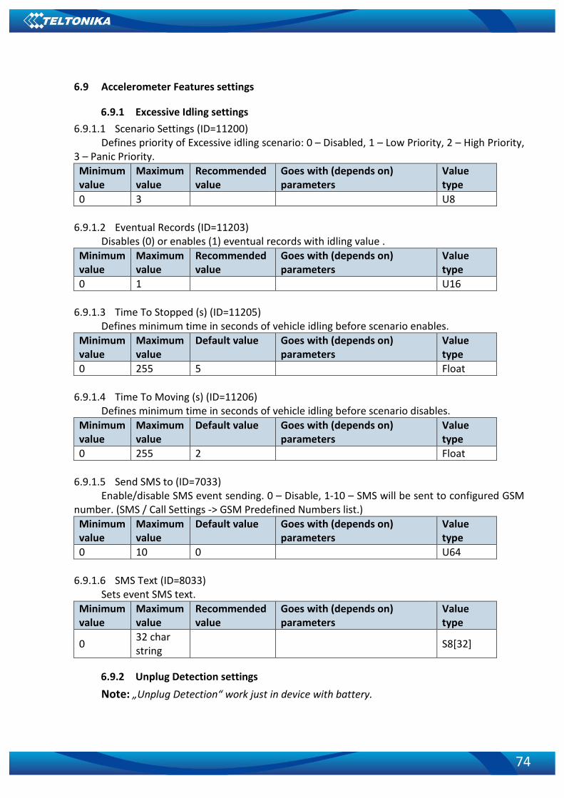
74
6.9 Accelerometer Features settings
6.9.1 Excessive Idling settings 6.9.1.1 Scenario Settings (ID=11200)
Defines priority of Excessive idling scenario: 0 – Disabled, 1 – Low Priority, 2 – High Priority, 3 – Panic Priority. Minimum value
Maximum value
Recommended value
Goes with (depends on) parameters
Value type
0 3 U8
6.9.1.2 Eventual Records (ID=11203) Disables (0) or enables (1) eventual records with idling value .
Minimum value
Maximum value
Recommended value
Goes with (depends on) parameters
Value type
0 1 U16
6.9.1.3 Time To Stopped (s) (ID=11205) Defines minimum time in seconds of vehicle idling before scenario enables.
Minimum value
Maximum value
Default value Goes with (depends on) parameters
Value type
0 255 5 Float
6.9.1.4 Time To Moving (s) (ID=11206) Defines minimum time in seconds of vehicle idling before scenario disables.
Minimum value
Maximum value
Default value Goes with (depends on) parameters
Value type
0 255 2 Float 6.9.1.5 Send SMS to (ID=7033)
Enable/disable SMS event sending. 0 – Disable, 1-10 – SMS will be sent to configured GSM number. (SMS / Call Settings -> GSM Predefined Numbers list.) Minimum value
Maximum value
Default value Goes with (depends on) parameters
Value type
0 10 0 U64
6.9.1.6 SMS Text (ID=8033) Sets event SMS text.
Minimum value
Maximum value
Recommended value
Goes with (depends on) parameters
Value type
0 32 char string S8[32]
6.9.2 Unplug Detection settings Note: „Unplug Detection“ work just in device with battery.

75
6.9.2.1 Scenario Settings (ID=11500) Sets priority of the scenario: 0 – Disable, 1 – Low Priority, 2 – High Priority, 3 – Panic
Priority. Minimum value
Maximum value
Default value Goes with (depends on) parameters
Value type
0 3 0 U64
6.9.2.2 Eventual Records (ID=11501) If enabled, only eventual records of unplug detection will be sent. 0 – Disable, 1 – Enable.
Minimum value
Maximum value
Default value Goes with (depends on) parameters
Value type
0 1 1 U64
6.9.2.3 Unplug Detection Mode (ID=11502) Sets Unplug detection mode. 0 – Simple, 1 – Advanced. Simple – unplug detection
according to external voltage only. Advanced – unplug detection according to: external voltage OR accelerometer. Minimum value
Maximum value
Default value Goes with (depends on) parameters
Value type
0 1 0 U64
6.9.2.4 Send SMS To (ID=7036) Enable/disable SMS event sending. 0 – Disable, 1-10 – SMS will be sent to configured GSM
number. (SMS / Call Settings -> GSM Predefined Numbers list.) Minimum value
Maximum value
Default value Goes with (depends on) parameters
Value type
0 10 0 U64
6.9.2.5 SMS Text (ID=8036) Configure unplug SMS event text here.
Minimum value
Maximum value
Default value Goes with (depends on) parameters
Value type
0 160 “Unplug” U64
6.9.3 Towing Detection
6.9.3.1 Scenario Settings (ID=11600) Sets priority of the scenario: 0 – Disable, 1 – Low Priority, 2 – High Priority, 3 – Panic
Priority. Minimum value
Maximum value
Default value Goes with (depends on) parameters
Value type
0 3 0 U64

76
6.9.3.2 Eventual Records (ID=11601) Sets priority of the scenario: 0 – Disable, 1 – Enable.
Minimum value
Maximum value
Default value Goes with (depends on) parameters
Value type
0 1 0 U8
6.9.3.3 Activation Timeout (min) (ID=11602) Activation timeout in minutes.
Minimum value
Maximum value
Default value Goes with (depends on) parameters
Value type
0 1 0 U8
6.9.3.4 Event Timeout (s) (ID=11603) Event timeout in minutes.
Minimum value
Maximum value
Default value Goes with (depends on) parameters
Value type
0 1 0 U8
6.9.3.5 Threshold (g) (ID=11605) Activation timeout in minutes.
Minimum value
Maximum value
Default value Goes with (depends on) parameters
Value type
0 1 0 U8
6.9.3.6 Angle (deg) (ID=11606) Towing angle in degrees.
Minimum value
Maximum value
Default value Goes with (depends on) parameters
Value type
0 1 0 U8
6.9.3.7 Duration (ms) (ID=11607) Towing duration in miliseconds.
Minimum value
Maximum value
Default value Goes with (depends on) parameters
Value type
0 1 0 U8
6.9.3.8 Make call to (ID=11604) Enable/disable event call. 0 – Disable, 1-10 – call will be made to configured GSM number.
(SMS / Call Settings -> GSM Predefined Numbers list.) Minimum value
Maximum value
Default value Goes with (depends on) parameters
Value type
0 1 0 U8
6.9.3.9 Send SMS To (ID=7035) Enable/disable SMS event sending. 0 – Disable, 1-10 – SMS will be sent to configured GSM
number. (SMS / Call Settings -> GSM Predefined Numbers list.)

77
Minimum value
Maximum value
Default value Goes with (depends on) parameters
Value type
0 10 0 U64
6.9.3.10 SMS Text (ID=8035) Activation timeout in minutes.
Minimum value
Maximum value
Default value Goes with (depends on) parameters
Value type
0 32 char string “Towing” S8[32]
6.9.4 Crash Detection
6.9.4.1 Scenario Settings (ID=11400) Sets priority of the scenario: 0 – Disable, 1 – Low Priority, 2 – High Priority, 3 – Panic
Priority. Minimum value
Maximum value
Default value Goes with (depends on) parameters
Value type
0 3 0 U64
6.9.4.2 Duration (ms) (ID=11401) Crash duration in milliseconds.
Minimum value
Maximum value
Default value Goes with (depends on) parameters
Value type
0 2000 5 U64
6.9.4.3 Threshold (mg) (ID=11402) Crash force threshold in mg.
Minimum value
Maximum value
Default value Goes with (depends on) parameters
Value type
0 7900 1500 U64
6.9.4.4 Send SMS To (ID=7037) Enable/disable SMS event sending. 0 – Disable, 1-10 – SMS will be sent to configured GSM
number. (SMS / Call Settings -> GSM Predefined Numbers list.) Minimum value
Maximum value
Default value Goes with (depends on) parameters
Value type
0 10 0 U64
6.9.4.5 SMS Text (ID=8037) SMS event text.
Minimum value
Maximum value
Default value Goes with (depends on) parameters
Value type
0 32 char string “Crash” S8[32]

78
6.9.4.6 Crash Trace (ID=11406) Crash trace parameter: 0 – OFF, 1 – ON.
Minimum value
Maximum value
Default value Goes with (depends on) parameters
Value type
0 1 0 U64
6.10 Auto Geofence settings
6.10.1.1 Scenario Settings (ID=20000) Defines priority of trip scenario: 0 – Disable, 1 – Low Priority, 2 – High Priority, 3 – Panic
Priority. Minimum value
Maximum value
Recommended value
Goes with (depends on) parameters
Value type
0 3 0 U8
6.10.1.2 Eventual Records (ID=20002) Eventual Records: 0 – Disable, 1 – Enable.
Minimum value
Maximum value
Recommended value
Goes with (depends on) parameters
Value type
0 1 0 U8 6.10.1.3 Generate Event (ID=20001)
Generate Event: 0 – On Exit, 1 – On Entrance, 2 – On Both. Minimum value
Maximum value
Recommended value
Goes with (depends on) parameters
Value type
0 1 0 U8 6.10.1.4 Activation Timeout (s) (ID=20003)
Parameter represents Auto Geofence activation timeout in seconds. Minimum value
Maximum value
Recommended value
Goes with (depends on) parameters
Value type
0 65535 60 AutoGeofencing priority (ID=20000) U16
6.10.1.5 Radius (m) (ID=20004)
Parameter represents radius of circle with center device coordinates after activating Auto Geofence feature. Minimum value
Maximum value
Recommended value
Goes with (depends on) parameters
Value type
0 1000000 100 AutoGeofencing priority (ID=20000) Deactivate by (ID=20005) U32
6.10.1.6 Send SMS To (ID=7030) Enable/disable SMS event sending. 0 – Disable, 1-10 – SMS will be sent to configured GSM
number. (SMS / Call Settings -> GSM Predefined Numbers list.)

79
Minimum value
Maximum value
Default value Goes with (depends on) parameters
Value type
0 10 0 U64
6.10.1.7 SMS Text (ID=8030) Defines event SMS Text.
Minimum value
Maximum value
Recommended value Goes with (depends on) parameters
Value type
0 32 char string “AutoGeofence” S8[32]
6.11 Manual Geofence
6.11.1 First Geozone parameters First Geozone parameters configuration. All 50 geozones are configured with the same
logic.
6.11.1.1 #1 Geozone Manual Geofencing priority (ID=20100) 0 – disabled, 1 – low, 2 – high, 3 – panic
Minimum value
Maximum value
Default value Goes with (depends on) parameters
Value type
0 3 0
#1 Geozone Manual Geofence event generating (ID=20101) #1 Geozone Eventual Records
(ID=20102) #1 Geozone Frame border
(ID=20103) #1 Geozone Shape type
(ID=20104) #1 Geozone Radius (ID=20105)
#1 Geozone X1 (ID=20106) #1 Geozone Y1 (ID=20107) #1 Geozone X2 (ID=20108) #1 Geozone X1 (ID=20109) #1 Geozone OverSpeeding
(ID=20110) #1 Geozone Max allowed speed
(ID=20111)
Uint8
6.11.1.2 #1 Geozone Manual Geofence event generating (ID=20101)
Generate event: 0 – No event, 1 - on exiting zone, 2 – on entering zone; 3 – on both;

80
Minimum value
Maximum value
Default value Goes with (depends on) parameters
Value type
0 3 0
#1 Geozone Manual Geofencing priority (ID=20100)
#1 Geozone Eventual Records (ID=20102)
#1 Geozone Frame border (ID=20103)
#1 Geozone Shape type (ID=20104)
#1 Geozone Radius (ID=20105) #1 Geozone X1 (ID=20106) #1 Geozone Y1 (ID=20107) #1 Geozone X2 (ID=20108) #1 Geozone X1 (ID=20109) #1 Geozone OverSpeeding
(ID=20110) #1 Geozone Max allowed speed
(ID=20111)
Uint8
6.11.1.3 #1 Geozone Eventual Records (ID=20102)
0 – disable, include parameter to all records, 1 – enable, include parameter to record only if event was generated.
Minimum value
Maximum value
Default value Goes with (depends on) parameters
Value type
0 1 1
#1 Geozone Manual Geofencing priority (ID=20100)
#1 Geozone Manual Geofence event generating (ID=20101)
#1 Geozone Frame border (ID=20103)
#1 Geozone Shape type (ID=20104)
#1 Geozone Radius (ID=20105) #1 Geozone X1 (ID=20106) #1 Geozone Y1 (ID=20107) #1 Geozone X2 (ID=20108) #1 Geozone X1 (ID=20109) #1 Geozone OverSpeeding
(ID=20110) #1 Geozone Max allowed speed
(ID=20111)
Uint8
6.11.1.4 #1 Geozone Frame border (ID=20103)
Frame border is an additional border around Geofence zone.

81
Minimum value
Maximum value
Default value Goes with (depends on) parameters
Value type
0 1000000 1
#1 Geozone Manual Geofencing priority (ID=20100)
#1 Geozone Manual Geofence event generating (ID=20101) #1 Geozone Eventual Records
(ID=20102) #1 Geozone Shape type
(ID=20104) #1 Geozone Radius (ID=20105)
#1 Geozone X1 (ID=20106) #1 Geozone Y1 (ID=20107) #1 Geozone X2 (ID=20108) #1 Geozone X1 (ID=20109) #1 Geozone OverSpeeding
(ID=20110) #1 Geozone Max allowed speed
(ID=20111)
Uint32
6.11.1.5 #1 Geozone Shape type (ID=20104)
Shape type: 0 – Circle, 1 - Rectangle.
Minimum value
Maximum value
Default value Goes with (depends on) parameters
Value type
0 1 0
#1 Geozone Manual Geofencing priority (ID=20100)
#1 Geozone Manual Geofence event generating (ID=20101) #1 Geozone Eventual Records
(ID=20102) #1 Geozone Frame border
(ID=20103) #1 Geozone Radius (ID=20105)
#1 Geozone X1 (ID=20106) #1 Geozone Y1 (ID=20107) #1 Geozone X2 (ID=20108) #1 Geozone X1 (ID=20109) #1 Geozone OverSpeeding
(ID=20110) #1 Geozone Max allowed speed
(ID=20111)
Uint8
6.11.1.6 #1 Geozone Radius (ID=20105)
Radius of circle when circular zone is used (radius in meters).

82
Minimum value
Maximum value
Default value Goes with (depends on) parameters
Value type
5 1000000 5
#1 Geozone Manual Geofencing priority (ID=20100)
#1 Geozone Manual Geofence event generating (ID=20101) #1 Geozone Eventual Records
(ID=20102) #1 Geozone Frame border
(ID=20103) #1 Geozone Shape type
(ID=20104) #1 Geozone X1 (ID=20106) #1 Geozone Y1 (ID=20107) #1 Geozone X2 (ID=20108) #1 Geozone X1 (ID=20109) #1 Geozone OverSpeeding
(ID=20110) #1 Geozone Max allowed speed
(ID=20111)
Uint32
6.11.1.7 #1 Geozone X1 (ID=20106) Geofence zone left bottom corner X coordinate (longitude).
Minimum value
Maximum value
Default value Goes with (depends on) parameters
Value type
-180 180 0
#1 Geozone Manual Geofencing priority (ID=20100)
#1 Geozone Manual Geofence event generating (ID=20101) #1 Geozone Eventual Records
(ID=20102) #1 Geozone Frame border
(ID=20103) #1 Geozone Shape type
(ID=20104) #1 Geozone Radius (ID=20105)
#1 Geozone Y1 (ID=20107) #1 Geozone X2 (ID=20108) #1 Geozone X1 (ID=20109) #1 Geozone OverSpeeding
(ID=20110) #1 Geozone Max allowed speed
(ID=20111)
Double
6.11.1.8 #1 Geozone Y1 (ID=20107)
Geofence zone left bottom corner Y coordinate (latitude).

83
Minimum value
Maximum value
Default value Goes with (depends on) parameters
Value type
-90 90 0
#1 Geozone Manual Geofencing priority (ID=20100)
#1 Geozone Manual Geofence event generating (ID=20101) #1 Geozone Eventual Records
(ID=20102) #1 Geozone Frame border
(ID=20103) #1 Geozone Shape type
(ID=20104) #1 Geozone Radius (ID=20105)
#1 Geozone X1 (ID=20106) #1 Geozone X2 (ID=20108) #1 Geozone X1 (ID=20109) #1 Geozone OverSpeeding
(ID=20110) #1 Geozone Max allowed speed
(ID=20111)
Double
6.11.1.9 #1 Geozone X2 (ID=20108) Geofence zone upper right corner X coordinate (longitude).
Minimum value
Maximum value
Default value Goes with (depends on) parameters
Value type
-180 180 0
#1 Geozone Manual Geofencing priority (ID=20100)
#1 Geozone Manual Geofence event generating (ID=20101) #1 Geozone Eventual Records
(ID=20102) #1 Geozone Frame border
(ID=20103) #1 Geozone Shape type
(ID=20104) #1 Geozone Radius (ID=20105)
#1 Geozone X1 (ID=20106) #1 Geozone Y1 (ID=20107) #1 Geozone X1 (ID=20109) #1 Geozone OverSpeeding
(ID=20110) #1 Geozone Max allowed speed
(ID=20111)
Double
6.11.1.10 #1 Geozone X1 (ID=20109)
Geofence zone upper right corner Y coordinate (latitude).
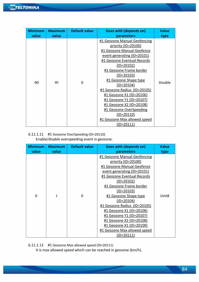
84
Minimum value
Maximum value
Default value Goes with (depends on) parameters
Value type
-90 90 0
#1 Geozone Manual Geofencing priority (ID=20100)
#1 Geozone Manual Geofence event generating (ID=20101) #1 Geozone Eventual Records
(ID=20102) #1 Geozone Frame border
(ID=20103) #1 Geozone Shape type
(ID=20104) #1 Geozone Radius (ID=20105)
#1 Geozone X1 (ID=20106) #1 Geozone Y1 (ID=20107) #1 Geozone X2 (ID=20108) #1 Geozone OverSpeeding
(ID=20110) #1 Geozone Max allowed speed
(ID=20111)
Double
6.11.1.11 #1 Geozone OverSpeeding (ID=20110)
Enable/disable overspeeding event in geozone.
Minimum value
Maximum value
Default value Goes with (depends on) parameters
Value type
0 1 0
#1 Geozone Manual Geofencing priority (ID=20100)
#1 Geozone Manual Geofence event generating (ID=20101) #1 Geozone Eventual Records
(ID=20102) #1 Geozone Frame border
(ID=20103) #1 Geozone Shape type
(ID=20104) #1 Geozone Radius (ID=20105)
#1 Geozone X1 (ID=20106) #1 Geozone Y1 (ID=20107) #1 Geozone X2 (ID=20108) #1 Geozone X1 (ID=20109)
#1 Geozone Max allowed speed (ID=20111)
Uint8
6.11.1.12 #1 Geozone Max allowed speed (ID=20111)
It is max allowed speed which can be reached in geozone (km/h).

85
Minimum value
Maximum value
Default value Goes with (depends on) parameters
Value type
0 1000 90
#1 Geozone Manual Geofencing priority (ID=20100)
#1 Geozone Manual Geofence event generating (ID=20101) #1 Geozone Eventual Records
(ID=20102) #1 Geozone Frame border
(ID=20103) #1 Geozone Shape type
(ID=20104) #1 Geozone Radius (ID=20105)
#1 Geozone X1 (ID=20106) #1 Geozone Y1 (ID=20107) #1 Geozone X2 (ID=20108) #1 Geozone X1 (ID=20109) #1 Geozone OverSpeeding
(ID=20110)
Uint16
6.11.2 Other Geozones Other Geozone’s parameters have the same logic as shown in Geozone #1.
GeoFence Zone
Number
Geofence Zone’s
parameters 1 20100-20111 2 20120-20131 3 20140-20151 … … 49 21060-21071 50 21080-21091
6.11.2.1 Send sms to #1-5 Geozone (ID=7025-7029), #6-50 Geozone (ID=7071-7115) Enable/disable sms event sending. 0 – Disable, 1-10 – sms will be sent to configured GSM
number. Minimum
value Maximum
value Default value Goes with (depends on)
parameters Value type
0 10 0
GSM Predefined Numbers (ID=6000-6009)
SMS Text #1-5 Geozone (ID=8025-8029), #6-50 Geozone
Uint8

86
(ID=8071-8115)
6.11.2.2 SMS Text #1-5 Geozone (ID=8025-8029), #6-50 Geozone (ID=8071-8115)
Configure geozone # sms event text here. Minimum
value Maximum
value Default value Goes with (depends on)
parameters Value type
0 160 Geozone Zone # Send sms to #1-5 Geozone
(ID=7025-7029), #6-50 Geozone (ID=7071-7115)
S8[160]
6.12 Trip / Odometer
6.12.1.1 Scenario Settings (ID=11800) Defines priority of trip scenario: 0 – Disabled, 1 – Low Priority, 2 – High Priority, 3 – Panic
Priority. Minimum value
Maximum value
Default value Goes with (depends on) parameters
Value type
0 3 0 U8
6.12.1.2 Eventual Records (ID=11801) Eventual Records: 0 – Disabled, 1 – Enabled.
Minimum value
Maximum value
Default value Goes with (depends on) parameters
Value type
0 1 0 U8 6.12.1.3 Mode (ID=11802)
For this feature I/O Odometer must be enabled. If I/O Odometer is enabled, and mode is set to Continuous (value 0), Trip distance is going to be counted till the end of trip, if between records mode is set, Odometer will count distance only between two records. Minimum value
Maximum value
Recommended value
Goes with (depends on) parameters
Value type
0 1 Trip priority priority (ID=11800) U8 6.12.1.4 Start Speed (km/h) (ID=11803)
This parameter represents speed, which is detected as minimum speed to indicate Trip Start and generate event. Minimum value
Maximum value
Recommended value
Goes with (depends on) parameters
Value type
0 255 Trip priority priority (ID=11800) U8 6.12.1.5 Ignition OFF Timeout (s) (ID=11804)
This parameter represents timeout to wait if ignition is off in order to detect Trip Stop and generate event.

87
Minimum value
Maximum value
Recommended value
Goes with (depends on) parameters
Value type
0 65535 Trip priority priority (ID=11800) U16
6.12.1.6 Send SMS To (ID=7031) Enable/disable SMS event sending. 0 – Disable, 1-10 – SMS will be sent to configured GSM
number. (SMS / Call Settings -> GSM Predefined Numbers list.) Minimum value
Maximum value
Default value Goes with (depends on) parameters
Value type
0 10 0 U64
6.12.1.7 SMS Text (ID=8031) Defines event SMS Text.
Minimum value
Maximum value
Recommended value Goes with (depends on) parameters
Value type
0 32 char string “Trip” S8[32]
6.12.1.8 Eco Score Allowed Events (ID=11804)
This parameter represents how many eco score events are allowed. Minimum value
Maximum value
Recommended value
Goes with (depends on) parameters
Value type
- - U16
6.12.1.9 Calculation Source (ID=11806) This parameter represents odometer calculation source: 0 – GNSS, 1 – OBD.
Minimum value
Maximum value
Recommended value
Goes with (depends on) parameters
Value type
0 1 U16
6.12.1.10 Odometer value (km) (ID=11807) Represents odometer value.
Minimum value
Maximum value
Recommended value
Goes with (depends on) parameters
Value type
0 99999999 U16
6.13 blue-tooth settings
6.13.1.1 BT Radio (ID=800) Enables or disable blue-tooth feature. 0 – Disabled, 1 – Enable (hidden), 2 – Enable
(visible). Minimum value
Maximum value
Default value Goes with (depends on) parameters
Value type
0 2 0 U64

88
6.13.1.2 Local Name (ID 801) Parameter defines a visible name of FM3001X device.
Minimum value
Maximum value
Default value Goes with (depends on) parameters
Value type
0 Symbols
30 Symbols String
6.13.1.3 Local PIN (ID=802)
Parameter Lets to configure blue-tooth PIN. Minimum value
Maximum value
Default value Goes with (depends on) parameters
Value type
0 Symbols 4 Symbols 5555 String
6.13.1.4 Security Mode (ID=803)
Parameter defines a security mode of FM3001X device. 0 – PIN only, 1 – PIN + MAC list, 2 – MAC list only, 3 – None.
Minimum value
Maximum value
Default value Goes with (depends on) parameters
Value type
0 3 0 U64
6.13.1.5 Connection Mode (ID=807) Settings for automatic connection: 0 – None, 1 – Data Link.
Minimum value
Maximum value
Default value Goes with (depends on) parameters
Value type
0 3 0 U64
6.13.1.6 External MAC (ID=804) Defines external device’s MAC, for FM3001 to auto connect to.
Minimum value
Maximum value
Default value Goes with (depends on) parameters
Value type
0 symbols 12 symbols 0 string
6.13.1.7 External Name (ID=805)
Defines external device’s name, for FM3001 to auto connect to. Minimum value
Maximum value
Default value Goes with (depends on) parameters
Value type
0 symbols 30 symbols 0 string
6.13.1.8 External PIN (ID=806)
Defines external device’s PIN, for FM3001 to auto connect to. Minimum value
Maximum value
Default value Goes with (depends on) parameters
Value type
0 symbols 8 symbols 0 string
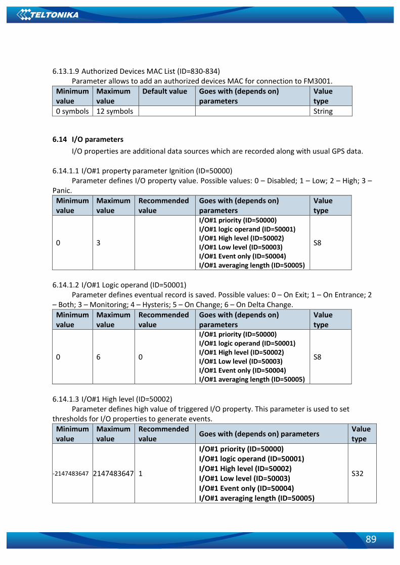
89
6.13.1.9 Authorized Devices MAC List (ID=830-834)
Parameter allows to add an authorized devices MAC for connection to FM3001. Minimum value
Maximum value
Default value Goes with (depends on) parameters
Value type
0 symbols 12 symbols String
6.14 I/O parameters I/O properties are additional data sources which are recorded along with usual GPS data.
6.14.1.1 I/O#1 property parameter Ignition (ID=50000) Parameter defines I/O property value. Possible values: 0 – Disabled; 1 – Low; 2 – High; 3 –
Panic. Minimum value
Maximum value
Recommended value
Goes with (depends on) parameters
Value type
0 3
I/O#1 priority (ID=50000) I/O#1 logic operand (ID=50001) I/O#1 High level (ID=50002) I/O#1 Low level (ID=50003) I/O#1 Event only (ID=50004) I/O#1 averaging length (ID=50005)
S8
6.14.1.2 I/O#1 Logic operand (ID=50001)
Parameter defines eventual record is saved. Possible values: 0 – On Exit; 1 – On Entrance; 2 – Both; 3 – Monitoring; 4 – Hysteris; 5 – On Change; 6 – On Delta Change. Minimum value
Maximum value
Recommended value
Goes with (depends on) parameters
Value type
0 6 0
I/O#1 priority (ID=50000) I/O#1 logic operand (ID=50001) I/O#1 High level (ID=50002) I/O#1 Low level (ID=50003) I/O#1 Event only (ID=50004) I/O#1 averaging length (ID=50005)
S8
6.14.1.3 I/O#1 High level (ID=50002)
Parameter defines high value of triggered I/O property. This parameter is used to set thresholds for I/O properties to generate events. Minimum value
Maximum value
Recommended value Goes with (depends on) parameters Value
type
-2147483647 2147483647 1
I/O#1 priority (ID=50000) I/O#1 logic operand (ID=50001) I/O#1 High level (ID=50002) I/O#1 Low level (ID=50003) I/O#1 Event only (ID=50004) I/O#1 averaging length (ID=50005)
S32

90
6.14.1.4 I/O#1 Low level (ID=50003) Parameter defines low value of triggered I/O property. This parameter is used to set
thresholds for I/O properties to generate events. Minimum value
Maximum value
Recommended value Goes with (depends on) parameters Value
type
-2147483647 2147483647 0
I/O#1 priority (ID=50000) I/O#1 logic operand (ID=50001) I/O#1 High level (ID=50002)
I/O#1 Low level (ID=50003) I/O#1 Event only (ID=50004) I/O#1 averaging length (ID=50005)
S32
6.14.1.5 I/O#1 Event only (ID=50004)
Parameter defines whether element should be sent only when event is generated. Possible values:
1 – Yes (parameter ID and value is sent when event is generated); 0 – No (parameter ID and value is sent in every record).
Minimal value
Maximum value
Recommended value
Goes with (depends on) parameters
Value type
0 1 0
I/O#1 priority (ID=50000) I/O#1 logic operand (ID=50001) I/O#1 High level (ID=50002) I/O#1 Low level (ID=50003) I/O#1 Event only (ID=50004) I/O#1 averaging length (ID=50005)
S8
6.14.1.6 I/O#1 averaging length (ID=50005)
Parameter defines I/O property sample length to average. If no averaging needed default value is 1. Minimum value
Maximum value
Recommended value Goes with (depends on) parameters Value
type
0 2147483647 1
I/O#1 priority (ID=50000) I/O#1 logic operand (ID=50001) I/O#1 High level (ID=50002) I/O#1 Low level (ID=50003) I/O#1 Event only (ID=50004) I/O#1 averaging length (ID=50005)
S32

91
Other I/O property elements can be configured in same logic. All I/O element parameters are listed in the next table.
6.14.2 I/O elements parameters and types. Parameter ID
Parameter Type Default value
Value range Parameter name
Min Max 50000 Uint8 1 0 3 Ignition Priority 50001 Uint8 5 0 6 Ignition Operand 50002 Uint8 0 0 1 Ignition High level 50003 Uint8 0 0 1 Ignition Low level 50004 Uint8 0 0 1 Ignition Event only 50005 Uint16 10 0 65535 Ignition Average 7000 Uint8 0 0 10 Send SMS 8000 String 0 0 160 SMS Text 50010 Uint8 1 0 3 Movement Priority 50011 Uint8 5 0 6 Movement Operand 50012 Uint8 0 0 1 Movement High level 50013 Uint8 0 0 1 Movement Low level 50014 Uint8 0 0 1 Movement Event only 50015 Uint16 1 0 65535 Movement Average 7001 Uint8 0 0 10 Send SMS 8001 String 0 0 160 SMS Text 50020 Uint8 1 0 3 Data Mode Priority 50021 Uint8 5 0 6 Data Mode Operand 50022 Uint8 0 0 5 Data Mode Hight level 50023 Uint8 0 0 5 Data Mode Low level 50024 Uint8 0 0 1 Data Mode Event only 7002 Uint8 0 0 10 Send SMS 8002 String 0 0 160 SMS Text 50030 Uint8 1 0 3 GSM Signal Priority 50031 Uint8 5 0 6 GSM Signal Operand 50032 Uint8 0 0 5 GSM Signal Hight level 50033 Uint8 0 0 5 GSM Signal Low level 50034 Uint8 0 0 1 GSM Signal Event only 50035 Uint16 1 0 65535 GSM Signal Average 7003 Uint8 0 0 10 Send SMS 8003 String 0 0 160 SMS Text 50040 Uint8 1 0 3 Deep Sleep Priority 50041 Uint8 3 0 6 Deep Sleep Operand 50042 Uint8 0 0 2 Deep Sleep Hight level 50043 Uint8 0 0 2 Deep Sleep Low level 50044 Uint8 0 0 1 Deep Sleep Event only 7004 Uint8 0 0 10 Send SMS 8004 String 0 0 160 SMS Text 50050 Uint8 1 0 3 GNSS Status Priority 50051 Uint8 5 0 6 GNSS Status Operand 50052 Uint8 0 0 5 GNSS Status Hight level

92
50053 Uint8 0 0 5 GNSS Status Low level 50053 Uint8 0 0 1 GNSS Status Event only 7005 Uint8 0 0 10 Send SMS
8005 String 0 0 160 SMS Text
50060 Uint8 0 0 3 GNSS PDOP Priority
5006 Uint8 3 0 6 GNSS PDOP Operand 5006 Uint16 0 0 1000 GNSS PDOP Hight level 5006 Uint16 0 0 1000 GNSS PDOP Low level 5006 Uint8 0 0 1 GNSS PDOP Event only 5006 Uint16 10 0 65535 GNSS PDOP Average 7006 Uint8 0 0 10 Send SMS 8006 String 0 0 160 SMS Text 50070 Uint8 1 0 3 GNSS HDOP Priority 50071 Uint8 3 0 6 GNSS HDOP Operand 50072 Uint16 0 0 1000 GNSS HDOP Hight level 50073 Uint16 0 0 1000 GNSS HDOP Low level 50074 Uint8 0 0 1 GNSS HDOP Event only 50075 Uint16 10 0 65535 GNSS HDOP Average 7007 Uint8 0 0 10 Send SMS 8007 String 0 0 160 SMS Text 50080 Uint8 1 0 3 External Voltage
50081 Uint8 6 0 6 External Voltage 50082 Uint16 1000 0 60000 External Voltage Hight
50083 Uint16 0 0 60000 External Voltage Low 50084 Uint8 0 0 1 External Voltage Event 50085 Uint16 10 0 65535 External Voltage
7008 Uint8 0 0 10 Send SMS 8008 String 0 0 160 SMS Text 50090 Uint8 1 0 3 Speed Priority 50091 Uint8 3 0 6 Speed Operand 50092 Uint16 0 0 300 Speed Hight level 50093 Uint16 0 0 300 Speed Low level 50094 Uint8 0 0 1 Speed Event only 50095 Uint16 1 0 65535 Speed Average 7009 Uint8 0 0 10 Send SMS 8009 String 0 0 160 SMS Text 50100 Uint8 0 0 3 GSM Cell ID Priority 50101 Uint8 3 0 6 GSM Cell ID Operand 50102 Uint32 0 0 999999 GSM Cell ID Hight level 50103 Uint32 0 0 999999 GSM Cell ID Low level 50104 Uint8 0 0 1 GSM Cell ID Event only 7010 Uint8 0 0 10 Send SMS 8010 String 0 0 160 SMS Text 50110 Uint8 0 0 3 GSM Area Code Priority 50111 Uint8 3 0 6 GSM Area Code
50112 Uint32 0 0 999999 GSM Area Code Hight

93
50113 Uint32 0 0 999999 GSM Area Code Low 50114 Uint8 0 0 1 GSM Area Code Event 7011 Uint8 0 0 10 Send SMS
8011 String 0 0 160 SMS Text 50120 Uint8 1 0 3 Battery Voltage Priority 50121 Uint8 3 0 6 Battery Voltage
50122 Uint16 0 0 5000 Battery Voltage Hight 50123 Uint16 0 0 5000 Battery Voltage Low 50124 Uint8 0 0 1 Battery Voltage Event 50125 Uint8 0 0 10 Battery Voltage
7012 Uint8 0 0 10 Send SMS 8012 String 0 0 160 SMS Text 50130 Uint8 1 0 3 Battery Current Priority 50131 Uint8 3 0 6 Battery Current
50132 Uint16 0 0 5000 Battery Current Hight 50133 Uint16 0 0 5000 Battery Current Low 50134 Uint8 0 0 1 Battery Current Event 50135 Uint8 0 0 10 Battery Current
7013 Uint8 0 0 10 Send SMS 8013 String 0 0 160 SMS Text
50140 Uint8 0 0 3 Active GSM Operator Priority
50141 Uint8 5 0 6 Active GSM Operator 50142 Uint32 0 0 999999 Active GSM Operator
50143 Uint32 0 0 999999 Active GSM Operator 50144 Uint8 0 0 1 Active GSM Operator
7014 Uint8 0 0 10 Send SMS 8014 String 0 0 160 SMS Text 50150 Uint8 0 0 3 Trip Odometer Priority 50151 Uint8 3 0 6 Trip Odometer
50152 Uint32 0 0 1000000 Trip Odometer Hight 50153 Uint32 0 0 1000000 Trip Odometer Low 50154 Uint8 0 0 1 Trip Odometer Event 7015 Uint8 0 0 10 Send SMS
8015 String 0 0 160 SMS Text 50160 Uint8 0 0 3 Total Odometer Priority 50161 Uint8 3 0 6 Total Odometer
50162 Uint32 0 0 10000000 Total Odometer Hight 50163 Uint32 0 0 10000000 Total Odometer Low 50164 Uint8 0 0 1 Total Odometer Event 7016 Uint8 0 0 10 Send SMS
8016 String 0 0 160 SMS Text 7017 Uint8 0 0 10 Send SMS 8017 String 0 0 160 SMS Text 7018 Uint8 0 0 10 Send SMS 8018 String 0 0 160 SMS Text 7019 Uint8 0 0 10 Send SMS 8019 String 0 0 160 SMS Text

94
50200 Uint8 0 0 3 Fuel Used GPS Priority 50201 Uint8 3 0 6 Fuel Used GPS Operand 50202 Uint32 0 0 1000000 Fuel Used GPS Hight
50203 Uint32 0 0 1000000 Fuel Used GPS Low 50204 Uint8 0 0 1 Fuel Used GPS Event 50205 Uint16 1 0 65535 Fuel Used GPS Average
7020 Uint8 0 0 10 Send SMS 8020 String 0 0 160 SMS Text 50210 Uint8 0 0 3 Fuel Rate GPS Priority 50211 Uint8 3 0 6 Fuel Rate GPS Operand 50212 Uint32 0 0 1000000 Fuel Rate GPS Hight
50213 Uint32 0 0 1000000 Fuel Rate GPS Low level 50214 Uint8 0 0 1 Fuel Rate GPS Event
50215 Uint16 1 0 65535 Fuel Rate GPS Average 7021 Uint8 0 0 10 Send SMS 8021 String 0 0 160 SMS Text 50220 Uint8 0 0 3 Axis X Priority 50221 Uint8 3 0 6 Axis X Operand 50222 Uint16 0 -8000 8000 Axis X Hight level 50223 Uint16 0 -8000 8000 Axis X Low level 50224 Uint8 0 0 1 Axis X Event only 50225 Uint16 1 0 65535 Axis X Average 7022 Uint8 0 0 10 Send SMS 8022 String 0 0 160 SMS Text 50230 Uint8 0 0 3 Axis Y Priority 50231 Uint8 3 0 6 Axis Y Operand 50232 Uint16 0 -8000 8000 Axis Y Hight level 50233 Uint16 0 -8000 8000 Axis Y Low level 50234 Uint8 0 0 1 Axis Y Event only 50235 Uint16 1 0 65535 Axis Y Average 7023 Uint8 0 0 10 Send SMS 8023 String 0 0 160 SMS Text 50240 Uint8 0 0 3 Axis Z Priority 50241 Uint8 3 0 6 Axis Z Operand 50242 Uint16 0 -8000 8000 Axis Z Hight level
50243 Uint16 0 -8000 8000 Axis Z Low level
50244 Uint8 0 0 1 Axis Z Event only 50245 Uint16 1 0 65535 Axis Z Average 7024 Uint8 0 0 10 Send SMS 8024 String 0 0 160 SMS Text

95
6.15 OBD settings OBD settings are confiburable just as I/O Elements parameters.
6.15.1 OBD elements parameters and types Parameter ID
Parameter Type
Default value
Value range Parameter name
Min Max 40100 Uint8 0 0 3 Number Of DTC Priority 40101 Uint8 3 0 6 Number Of DTC Operand 40102 Uint8 0 0 255 Number Of DTC High level 40103 Uint8 0 0 255 Number Of DTC Low level 40104 Uint8 0 0 1 Number Of DTC Event only 7038 Uint8 0 0 10 Number Of DTC Send SMS 8038 String 0 0 160 Number Of DTC SMS Text 40110 Uint8 0 0 3 Engine Load Priority 40111 Uint8 3 0 6 Engine Load Operand 40112 Uint8 0 0 100 Engine Load High level 40113 Uint8 0 0 100 Engine Load Low level 40114 Uint8 0 0 1 Engine Load Event only 7039 Uint8 0 0 10 Engine Load Send SMS 8039 String 0 0 160 Engine Load SMS Text 40120 Uint8 0 0 3 Coolant Temperature Priority 40121 Uint8 3 0 6 Coolant Temperature Operand 40122 Int8 0 -40 215 Coolant Temperature e Hight level 40123 Int8 0 -40 215 Coolant Temperature Low level 40124 Uint8 0 0 1 Coolant Temperature Event only 7040 Uint8 0 0 10 Coolant Temperature Send SMS 8040 String 0 0 160 Coolant Temperature SMS Text 40130 Uint8 0 0 3 Short Fuel Trim Priority 40131 Uint8 3 0 6 Short Fuel Trim Operand 40132 Uint8 0 0 255 Short Fuel Trim Hight level 40133 Uint8 0 0 255 Short Fuel Trim Low level 401034 Uint8 0 0 1 Short Fuel Trim Event only 7003 Uint8 0 0 10 Short Fuel Trim Send SMS 8003 String 0 0 160 Short Fuel Trim SMS Text 40140 Uint8 0 0 3 Fuel Pressure Priority 40141 Uint8 3 0 6 Fuel Pressure Operand 40142 Uint16 0 0 765 Fuel Pressure Hight level 40143 Uint16 0 0 765 Fuel Pressure Low level 40144 Uint8 1 0 1 Fuel Pressure Event only 7042 Uint8 0 0 10 Fuel Pressure Send SMS 8042 String 0 0 160 Fuel Pressure SMS Text 40150 Uint8 0 0 3 Intake Map Priority 40151 Uint8 3 0 6 Intake Map Operand 40152 Uint8 0 0 255 Intake Map Hight level 40153 Uint8 0 0 255 Intake Map Low level 40153 Uint8 1 0 1 Intake Map Event only
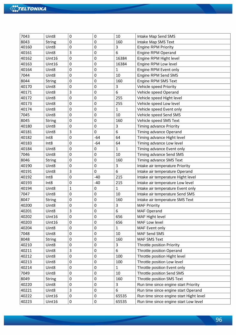
96
7043 Uint8 0 0 10 Intake Map Send SMS 8043 String 0 0 160 Intake Map SMS Text 40160 Uint8 0 0 3 Engine RPM Priority 40161 Uint8 3 0 6 Engine RPM Operand 40162 Uint16 0 0 16384 Engine RPM Hight level 40163 Uint16 0 0 16384 Engine RPM Low level 40164 Uint8 0 0 1 Engine RPM Event only 7044 Uint8 0 0 10 Engine RPM Send SMS 8044 String 0 0 160 Engine RPM SMS Text 40170 Uint8 0 0 3 Vehicle speed Priority 40171 Uint8 3 0 6 Vehicle speed Operand 40172 Uint8 0 0 255 Vehicle speed Hight level 40173 Uint8 0 0 255 Vehicle speed Low level 40174 Uint8 0 0 1 Vehicle speed Event only 7045 Uint8 0 0 10 Vehicle speed Send SMS 8045 String 0 0 160 Vehicle speed SMS Text 40180 Uint8 0 0 3 Timing advance Priority 40181 Uint8 3 0 6 Timing advance Operand 40182 Int8 0 -64 64 Timing advance Hight level 40183 Int8 0 -64 64 Timing advance Low level 40184 Uint8 0 0 1 Timing advance Event only 7046 Uint8 0 0 10 Timing advance Send SMS 8046 String 0 0 160 Timing advance SMS Text 40190 Uint8 0 0 3 Intake air temperature Priority 40191 Uint8 3 0 6 Intake air temperature Operand 40192 Int8 0 -40 215 Intake air temperature Hight level 40193 Int8 0 -40 215 Intake air temperature Low level 40194 Uint8 1 0 1 Intake air temperature Event only 7047 Uint8 0 0 10 Intake air temperature Send SMS 8047 String 0 0 160 Intake air temperature SMS Text 40200 Uint8 0 0 3 MAF Priority 40201 Uint8 3 0 6 MAF Operand 40202 Uint16 0 0 656 MAF Hight level 40203 Uint16 0 0 656 MAF Low level 40204 Uint8 0 0 1 MAF Event only 7048 Uint8 0 0 10 MAF Send SMS 8048 String 0 0 160 MAF SMS Text 40210 Uint8 0 0 3 Throttle position Priority 40211 Uint8 3 0 6 Throttle position Operand 40212 Uint8 0 0 100 Throttle position Hight level 40213 Uint8 0 0 100 Throttle position Low level 40214 Uint8 0 0 1 Throttle position Event only 7049 Uint8 0 0 10 Throttle position Send SMS 8049 String 0 0 160 Throttle position SMS Text 40220 Uint8 0 0 3 Run time since engine start Priority 40221 Uint8 3 0 6 Run time since engine start Operand 40222 Uint16 0 0 65535 Run time since engine start Hight level 40223 Uint16 0 0 65535 Run time since engine start Low level

97
40224 Uint8 0 0 1 Run time since engine start Event only 7050 Uint8 0 0 10 Run time since engine start Send SMS 8050 String 0 0 160 Run time since engine start SMS Text 40230 Uint8 0 0 3 Distance traveled MIL on Priority 40231 Uint8 3 0 6 Distance traveled MIL on Operand 40232 Uint16 0 0 65535 Distance traveled MIL on Hight level 40233 Uint16 0 0 65535 Distance traveled MIL on Low level 40234 Uint8 0 0 1 Distance traveled MIL on Event only 7051 Uint8 0 0 10 Distance traveled MIL on Send SMS 8051 String 0 0 160 Distance traveled MIL on SMS Text 40240 Uint8 0 0 3 Relative fuel rail pressure Priority 40241 Uint8 5 0 6 Relative fuel rail pressure Operand 40242 Uint16 0 0 5178 Relative fuel rail pressure Hight level 40243 Uint16 0 0 5178 Relative fuel rail pressure Low level 40244 Uint8 0 0 1 Relative fuel rail pressure Event only 7052 Uint8 0 0 10 Relative fuel rail pressure Send SMS 8052 String 0 0 160 Relative fuel rail pressure SMS Text 40250 Uint8 0 0 3 Direct fuel rail pressure Priority 40251 Uint8 3 0 6 Direct fuel rail pressure Operand 40252 Uint16 0 0 656 Direct fuel rail pressure Hight level 40253 Uint16 0 0 656 Direct fuel rail pressure Low level 40254 Uint8 0 0 1 Direct fuel rail pressure Event only 7053 Uint8 0 0 10 Direct fuel rail pressure Send SMS 8053 String 0 0 160 Direct fuel rail pressure SMS Text 40260 Uint8 0 0 3 Commanded EGR Priority 40261 Uint8 3 0 6 Commanded EGR Operand 40262 Uint8 0 0 100 Commanded EGR Hight level 40263 Uint8 0 0 100 Commanded EGR Low level 40264 Uint8 0 0 1 Commanded EGR Event only 7054 Uint8 0 0 10 Commanded EGR Send SMS 8054 String 0 0 160 Commanded EGR SMS Text 40270 Uint8 0 0 3 EGR error Priority 40271 Uint8 3 0 6 EGR error Operand 40272 Int8 0 -100 100 EGR error Hight level 40273 Int8 0 -100 100 EGR error Low level 40274 Uint8 0 0 1 EGR error Event only 7055 Uint8 0 0 10 EGR error Send SMS 8055 String 0 0 160 EGR error SMS Text 40280 Uint8 0 0 3 Fuel level Priority 40281 Uint8 3 0 6 Fuel level Operand 40282 Uint8 0 0 100 Fuel level Hight level 40283 Uint8 0 0 100 Fuel level Low level 40284 Uint8 0 0 1 Fuel level Event only 7056 Uint8 0 0 10 Fuel level Send SMS 8056 String 0 0 160 Fuel level SMS Text 40290 Uint8 0 0 3 Distance traveled since codes slear Priority 40291 Uint8 3 0 6 Distance traveled since codes slear Operand 40292 Uint16 0 0 65535 Distance traveled since codes slear Hight level

98
40293 Uint16 0 0 65535 Distance traveled since codes slear Low level 40294 Uint8 0 0 1 Distance traveled since codes slear Event only 7057 Uint8 0 0 10 Distance traveled since codes slear Send SMS 8057 String 0 0 160 Distance traveled since codes slear SMS Text 40300 Uint8 0 0 3 Barometric pressure Priority 40301 Uint8 3 0 6 Barometric pressure Operand 40302 Uint8 0 0 255 Barometric pressure Hight level 40303 Uint8 0 0 255 Barometric pressure Low level 40304 Uint8 0 0 1 Barometric pressure Event only 7058 Uint8 0 0 10 Barometric pressure Send SMS 8058 String 0 0 160 Barometric pressure SMS Text 40310 Uint8 0 0 3 Control module voltage Priority 40311 Uint8 3 0 6 Control module voltage Operand 40312 Uint16 0 0 65535 Control module voltage Hight level 40313 Uint16 0 0 65535 Control module voltage Low level 40314 Uint8 0 0 1 Control module voltage Event only 7059 Uint8 0 0 10 Control module voltage Send SMS 8059 String 0 0 160 Control module voltage SMS Text 40320 Uint8 0 0 3 Absolute load value Priority 40321 Uint8 3 0 6 Absolute load value Operand 40322 Uint16 0 0 25700 Absolute load value Hight level 40323 Uint16 0 0 25700 Absolute load value Low level 40324 Uint8 0 0 1 Absolute load value Event only 7060 Uint8 0 0 10 Absolute load value Send SMS 8060 String 0 0 160 Absolute load value SMS Text 40330 Uint8 0 0 3 Ambient air temperature Priority 40331 Uint8 3 0 6 Ambient air temperature Operand 40332 Int8 0 -40 215 Ambient air temperature Hight level 40333 Int8 0 -40 215 Ambient air temperature Low level 40334 Uint8 0 0 1 Ambient air temperature Event only 7061 Uint8 0 0 10 Ambient air temperature Send SMS 8061 String 0 0 160 Ambient air temperature SMS Text 40340 Uint8 0 0 3 Time run with MIL on Priority 40341 Uint8 3 0 6 Time run with MIL on Operand 40342 Uint16 0 0 65535 Time run with MIL on Hight level 40343 Uint16 0 0 65535 Time run with MIL on Low level 40344 Uint8 0 0 1 Time run with MIL on Event only 7062 Uint8 0 0 10 Time run with MIL on Send SMS 8062 String 0 0 160 Time run with MIL on SMS Text 40350 Uint8 0 0 3 Time since trouble codes cleared Priority 40351 Uint8 3 0 6 Time since trouble codes cleared Operand
40352 Uint16 0 0 65535 Time since trouble codes cleared Hight level
40353 Uint16 0 0 65535 Time since trouble codes cleared Low level
40354 Uint8 0 0 1 Time since trouble codes cleared Event only 7063 Uint8 0 0 10 Time since trouble codes cleared Send SMS 8063 String 0 0 160 Time since trouble codes cleared SMS Text

99
40360 Uint8 0 0 3 Absolute fuel rail pressure Priority 40361 Uint8 3 0 6 Absolute fuel rail pressure Operand 40362 Uint16 0 0 65535 Absolute fuel rail pressure Hight level 40363 Uint16 0 0 65535 Absolute fuel rail pressure Low level 40364 Uint8 0 0 1 Absolute fuel rail pressure Event only 7064 Uint8 0 0 10 Absolute fuel rail pressure Send SMS 8064 String 0 0 160 Absolute fuel rail pressure SMS Text 40370 Uint8 0 0 3 Hybrid battery pack remaining life Priority 40371 Uint8 3 0 6 Hybrid battery pack remaining life Operand 40372 Uint8 0 0 100 Hybrid battery pack remaining life Hight level 40373 Uint8 0 0 100 Hybrid battery pack remaining life Low level 40374 Uint8 0 0 1 Hybrid battery pack remaining life Event only 7065 Uint8 0 0 10 Hybrid battery pack remaining life Send SMS 8065 String 0 0 160 Hybrid battery pack remaining life SMS Text 40380 Uint8 0 0 3 Engine oil temperature Priority 40381 Uint8 3 0 6 Engine oil temperature Operand 40382 Int8 0 -40 210 Engine oil temperature Hight level 40383 Int8 0 -40 210 Engine oil temperature Low level 40384 Uint8 0 0 1 Engine oil temperature Event only 7066 Uint8 0 0 10 Engine oil temperature Send SMS 8066 String 0 0 160 Engine oil temperature SMS Text 40390 Uint8 0 0 3 Fuel injection timing Priority 40391 Uint8 3 0 6 Fuel injection timing Operand 40392 Int16 0 -21000 30200 Fuel injection timing Hight level 40393 Int16 0 -21000 30200 Fuel injection timing Low level 40394 Uint8 0 0 1 Fuel injection timing Event only 7067 Uint8 0 0 10 Fuel injection timing Send SMS 8067 String 0 0 160 Fuel injection timing SMS Text 40400 Uint8 0 0 3 Fuel Rate Priority 40401 Uint8 3 0 6 Fuel Rate Operand 40402 Uint16 0 0 32767 Fuel Rate Hight level 40403 Uint16 0 0 32767 Fuel Rate Low level 40404 Uint8 0 0 1 Fuel Rate Event only 7068 Uint8 0 0 10 Fuel Rate Send SMS 8068 String 0 0 160 Fuel Rate SMS Text 40000 Uint8 1 0 2 OBD Feature (0 - Disable, 1 - OBD, 2 - ELD) 40002 Uint16 10 2 65535 ELD data send period in seconds 40003 String - 17 17 ELD VIN

100
CHANGE LOG
Nr. Date Version Comments 1 2018-01-31 0.01 Preliminary draft release. 2 2018-02-22 0.02 Added system parameter Send SMS to description;
Modified technical details. 3 2018-03-20 0.03 Removed irrelevant info. 4 2018-05-23 0.04 Added ELD (Electronic Logging Device) functionality
description and ELD parameters IDs; Online deep sleep description modified.
5 2018-06-08 0.05 Added information about battery disposal; Added information about external fuse; Added new title page picture.
6 2018-06-12 0.06 Added Iinstaling FM 3001 drivers table and pictures 7 2018-07-25 0.07 Added Manual Geofencing description
Added Manual Geofencing configuration ID 8 2018-08-22 0.08 Blue-tooth description updated