FMB001 User Manual V0 - EuroDK · FMB001 User Manual V0.06. ... 6.7.9 Overspeeding priority ... 1...
81
FMB001 User Manual V0.06
Transcript of FMB001 User Manual V0 - EuroDK · FMB001 User Manual V0.06. ... 6.7.9 Overspeeding priority ... 1...
FMB001 User Manual V0.06

2
Table of contents 1 INTRODUCTION ..................................................................................................................... 6
1.1 ATTENTION ............................................................................................................................ 6 1.2 INSTRUCTIONS OF SAFETY ......................................................................................................... 6 1.3 LEGAL NOTICE ........................................................................................................................ 7 1.4 ABOUT DOCUMENT ................................................................................................................. 7
2 BASIC DESCRIPTION ............................................................................................................... 7
2.1 BASIC CHARACTERISTICS ........................................................................................................... 8 2.2 TECHNICAL FEATURES............................................................................................................... 9 2.3 TECHNICAL INFORMATION ABOUT INTERNAL BATTERY................................................................... 10 2.4 ELECTRICAL CHARACTERISTICS .................................................................................................. 11 2.5 ABSOLUTE MAXIMUM RATINGS ............................................................................................... 11
3 CONNECTION, PINOUT, ACCESSORIES .................................................................................. 12
3.1 HOW TO INSERT MICRO SIM CARD INTO FMB001 DEVICE: ........................................................... 12 3.2 INSTALLING FMB001 DRIVERS ................................................................................................ 14 3.3 OBD II ............................................................................................................................... 16 3.4 NAVIGATE LED ..................................................................................................................... 17 3.5 STATUS LED ........................................................................................................................ 17
4 OPERATIONAL BASICS .......................................................................................................... 17
4.1 OPERATIONAL PRINCIPALS....................................................................................................... 17 4.2 SLEEP MODE ........................................................................................................................ 17 4.3 VIRTUAL ODOMETER .............................................................................................................. 18 4.4 FEATURES ............................................................................................................................ 18
4.4.1 Green Driving Scenario. .......................................................................................... 18 4.4.2 Over Speeding Scenario. ......................................................................................... 19 4.4.3 Jamming detection ................................................................................................. 19 4.4.4 Trip.......................................................................................................................... 19
4.5 ACCELEROMETER SCENARIOS ................................................................................................... 19 4.5.1 Towing Detection.................................................................................................... 19 4.5.2 Unplug Detection .................................................................................................... 20 4.5.3 Crash Detection ...................................................................................................... 20
4.5.3.1 Crash Trace operation ........................................................................................................ 20
5 CONFIGURATION ................................................................................................................. 20
5.1 CONFIGURATOR .................................................................................................................... 20 5.1.1 System settings ....................................................................................................... 21 5.1.2 Records settings ...................................................................................................... 24 5.1.3 GSM settings, GPRS part ........................................................................................ 25 5.1.4 GSM settings, SMS part .......................................................................................... 26 5.1.5 SMS Event Time Zones ............................................................................................ 27 5.1.6 SMS events ............................................................................................................. 27 5.1.7 GSM settings, Operator list .................................................................................... 29 5.1.8 Features settings .................................................................................................... 30 5.1.9 Trip settings ............................................................................................................ 32 5.1.10 AutoGeofencing settings ........................................................................................ 33 5.1.11 GPS Fuel Counter .................................................................................................... 34 5.1.12 Scenarios Accelerometer ........................................................................................ 35 5.1.13 OBD II ...................................................................................................................... 38 5.1.14 Bluetooth ................................................................................................................ 39 5.1.15 Data Acquisition Mode settings.............................................................................. 40 5.1.16 Connecting to device via Bluetooth ........................................................................ 44
5.2 OBD FUNCTIONALITY DESCRIPTION........................................................................................... 44 5.2.1 Supported OBD protocols ....................................................................................... 44 5.2.2 General info ............................................................................................................ 44

3
5.2.3 Initialization ............................................................................................................ 44 5.2.4 Data ........................................................................................................................ 44
5.3 I/O SETTINGS ....................................................................................................................... 44
6 SMS COMMAND LIST ........................................................................................................... 47
6.1 SMS COMMAND LIST ............................................................................................................. 47 6.1.1 getinfo .................................................................................................................... 48 6.1.2 getver ..................................................................................................................... 48 6.1.3 getstatus ................................................................................................................. 48 6.1.4 getgps ..................................................................................................................... 48 6.1.5 ggps ........................................................................................................................ 49 6.1.6 readio # ................................................................................................................... 49 6.1.7 getparam ................................................................................................................ 49 6.1.8 setparam ................................................................................................................ 49 6.1.9 flush #,#,#,#,#,#,# ................................................................................................... 49 6.1.10 setdigout ................................................................................................................. 50 6.1.11 countrecs ................................................................................................................ 50 6.1.12 towingreact ............................................................................................................ 50 6.1.13 btgetlist .................................................................................................................. 50
6.2 SYSTEM PARAMETERS ............................................................................................................ 51 6.2.1 Sleep Mode (ID=102) .............................................................................................. 51 6.2.2 Sleep timeout (ID=103) ........................................................................................... 51 6.2.3 Movement Source (ID=100) .................................................................................... 51 6.2.4 Static Navigation (ID=106) ..................................................................................... 51 6.2.5 Saving/Sending without time synchronization (ID=107) ........................................ 51 6.2.6 GNSS Source (ID=109) ............................................................................................. 52 6.2.7 Ignition settings (ID=101) ....................................................................................... 52 6.2.8 High voltage level (ID=104) .................................................................................... 52 6.2.9 Low voltage level (ID=105) ..................................................................................... 52 6.2.10 Led indication (ID=108) ........................................................................................... 52
6.3 RECORDS PARAMETERS .......................................................................................................... 53 6.3.1 Sorting (ID=1002) ................................................................................................... 53 6.3.2 Open Link Timeout (ID=1000) ................................................................................. 53 6.3.3 Server Response Timeout (ID=1001) ....................................................................... 53
6.4 GSM PARAMETERS ............................................................................................................... 53 6.4.1 GPRS content activation (ID=2000) ....................................................................... 53 6.4.2 APN Name (ID=2001) ............................................................................................ 54 6.4.3 APN Name (ID=2001) ............................................................................................ 54 6.4.4 APN username (ID=2002) ..................................................................................... 54 6.4.5 APN Name (ID=2001) ............................................................................................ 54 6.4.6 APN Password (ID=2003) ...................................................................................... 54 6.4.7 APN Name (ID=2001) ............................................................................................ 54 6.4.8 Domain (ID=2004) .................................................................................................. 54 6.4.9 Target Server Port (ID=2005) .................................................................................. 55 6.4.10 Protocol (ID=2006) ................................................................................................ 55
6.5 SMS/CALL SETTINGS ............................................................................................................. 55 6.5.1 SMS data sending settings (ID=3000) ..................................................................... 55 6.5.2 Data send number (ID=3001) ................................................................................. 55 6.5.3 Data send number (ID=3001) ................................................................................. 55 6.5.4 Authorized phone numbers (ID=4000-4009) .......................................................... 56 6.5.5 SMS Event Predefined Numbers (ID=6000-6009) ................................................... 56 6.5.6 SMS Login (ID=3003) .............................................................................................. 56 6.5.7 SMS Password (ID=3004) ........................................................................................ 56 6.5.8 Incoming call action (ID=3005) ............................................................................... 56 6.5.9 Outgoing Call Trigger (ID=3007) ............................................................................. 56 6.5.10 GSM number index (ID=3008) ................................................................................ 57 6.5.11 Operator List (ID=5000-5049) ................................................................................. 57
6.6 DATA ACQUISITION MODES PARAMETERS .................................................................................. 57
4
6.6.1 Home Network GSM operator code “Vehicle on STOP” parameters ...................... 57 6.6.1.1 Min Period (ID=10000)........................................................................................................ 57 6.6.1.2 Min Saved Records (ID=10004) ........................................................................................... 57 6.6.1.3 Send Period (ID=10005) ...................................................................................................... 57
6.6.2 Home Network GSM operator code “Vehicle MOVING” parameters ..................... 57 6.6.2.1 Min Period (ID=10050)........................................................................................................ 57 6.6.2.2 Min Distance (ID=10051) .................................................................................................... 58 6.6.2.3 Min Angle (ID=10052) ......................................................................................................... 58 6.6.2.4 Min Speed delta (ID=10053) ............................................................................................... 58 6.6.2.5 Min Saved Records (ID=10054) ........................................................................................... 58 6.6.2.6 Send Period (ID=10055) ...................................................................................................... 59
6.6.3 Roaming Network GSM operator code “Vehicle on STOP” parameters ................. 59 6.6.3.1 Min Period (ID=10100)........................................................................................................ 59 6.6.3.2 Min Saved Records (ID=10104) ........................................................................................... 59 6.6.3.3 Send Period (ID=10105) ...................................................................................................... 59
6.6.4 Roaming Network GSM operator code “Vehicle MOVING” parameters ................ 59 6.6.4.1 Min Period (ID=10150)........................................................................................................ 59 Min Distance (ID=10151) .................................................................................................................... 59 6.6.4.2 Min Distance (ID=10151) .................................................................................................... 60 6.6.4.3 Min Angle (ID=10152) ......................................................................................................... 60 6.6.4.4 Min Speed (ID=10153) ........................................................................................................ 60 Min Distance (ID=10151) .................................................................................................................... 60 6.6.4.5 Min Saved Records (ID=10154) ........................................................................................... 60 6.6.4.6 Send Period (ID=10155) ...................................................................................................... 61
6.6.5 Unknown Network GSM operator code “Vehicle on STOP” parameters ................ 61 6.6.5.1 Min Period (ID=10200)........................................................................................................ 61 6.6.5.2 Min Saved Records (ID=10204) ........................................................................................... 61 6.6.5.3 Send Period (ID=10205) ...................................................................................................... 61
6.6.6 Unknown Network GSM operator code “Vehicle MOVING” parameters ............... 61 6.6.6.1 Min Period (ID=10250)........................................................................................................ 61 6.6.6.2 Min Distance (ID=10251) .................................................................................................... 62 Min Period (ID=10150) ....................................................................................................................... 62 6.6.6.3 Min Angle (ID=10252) ......................................................................................................... 62 6.6.6.4 Min Speed (ID=10253) ........................................................................................................ 62 Min Distance (ID=10151) .................................................................................................................... 62 6.6.6.5 Min Saved Records (ID=10254) ........................................................................................... 62 6.6.6.6 Send Period (ID=10255) ...................................................................................................... 63
6.7 FEATURES PARAMETERS ......................................................................................................... 63 6.7.1 Green driving priority (ID=11000) ........................................................................... 63 6.7.2 Max Acceleration Force (ID=11004) ....................................................................... 63 6.7.3 Max Braking Force (ID=11005) ............................................................................... 63 6.7.4 Max Cornering (ID=11006) ..................................................................................... 63 6.7.5 Green/Eco driving (ID=11007) ................................................................................ 63 6.7.6 Green driving digital output control settings (ID=11003) ....................................... 64 6.7.7 Green driving Digital output on duration (ID=11001) ............................................ 64 6.7.8 Green driving Digital output off duration (ID=11002) ............................................ 64 6.7.9 Overspeeding priority (ID=11100) .......................................................................... 64 6.7.10 Max allowed Speed (ID=11104) .............................................................................. 64 6.7.11 Overspeeding output control (ID=11103) ............................................................... 64 6.7.12 Overspeeding Digital output on duration (ID=11101) ............................................ 65 6.7.13 Overspeeding Digital output off duration (ID=11102) ............................................ 65 6.7.14 Excessive idling priority (ID=11200) ........................................................................ 65 6.7.15 Eventual records (ID=11203) .................................................................................. 65 6.7.16 Excessive idling minimum stop duration (ID=11205) .............................................. 65 6.7.17 Excessive idling minimum move duration (ID=11206) ............................................ 65 6.7.18 Excessive idling output control (ID=11204) ............................................................ 66 6.7.19 Excessive idling output on duration (ID=11201) ..................................................... 66 6.7.20 Excessive idling output off duration (ID=11202) ..................................................... 66 6.7.21 Jamming (ID=11300) .............................................................................................. 66 6.7.22 Jamming Eventual records (ID=11303) ................................................................... 66 6.7.23 Jamming Output Control (ID=11304) ..................................................................... 66

5
6.7.24 Jamming DOUT on duration [ms] (ID=11301) ........................................................ 67 6.7.25 Jamming DOUT off duration [ms] (ID=11302) ........................................................ 67 6.7.26 DOUT control via call (ID=12000) ........................................................................... 67 6.7.27 DOUT deactivation settings (ID=12001) ................................................................. 67 6.7.28 DOUT duration timeout [s] (ID=12002) .................................................................. 67 6.7.29 Trip priority priority (ID=11800) ............................................................................. 67 6.7.30 Start Speed (ID=11803) ........................................................................................... 68 6.7.31 Ignition Off Timeout (ID=11804) ............................................................................. 68 6.7.32 Trip mode (ID=11802) ............................................................................................. 68
6.8 AUTOGEOFENCING................................................................................................................ 68 6.8.1.1 AutoGeofencing priority (ID=20000) ................................................................................. 68 6.8.1.2 Activation Timeout (ID=20003) ......................................................................................... 68 6.8.1.3 Deactivate by (ID=20005) .................................................................................................. 68 6.8.1.4 AutoGeofence event generating (ID=20001) .................................................................... 69 6.8.1.5 Radius (ID=20004) .............................................................................................................. 69
6.9 GPS FUEL COUNTER .............................................................................................................. 69 6.9.1.1 City Consumption L/100km (ID=11900) ............................................................................ 69 6.9.1.2 Highway Consumption L/100km (ID=11901).................................................................... 69 6.9.1.3 Average Consumption L/100km (ID=11902) .................................................................... 69 6.9.1.4 City Speed [km/h] (ID=11903) ........................................................................................... 69 6.9.1.5 Highway Speed [km/h] (ID=11904) ................................................................................... 70 6.9.1.6 Average Speed [km/h] (ID=11905) .................................................................................... 70 6.9.1.7 Correction coefficient (ID=11906) ..................................................................................... 70 6.9.1.8 Fuel Consumption on Idling [L/h] (ID=11907) ................................................................... 70 6.9.1.9 Higher Speeds Add [%] (ID=11908) .................................................................................... 70 6.9.1.10 Highway Consumption every km/h (ID=11909) .............................................................. 70
6.10 SCENARIOS ACCELEROMETER................................................................................................... 70 6.10.1 Unplug Detection .................................................................................................... 70
6.10.1.1 Scenario settings (ID=11500) ............................................................................................ 70 6.10.1.2 Eventual records (ID=11501) ............................................................................................ 71 6.10.1.3 Unplug detection mode (ID=11502) ................................................................................. 71 6.10.1.4 Send sms to (ID=7067) ...................................................................................................... 71 6.10.1.5 SMS Text (ID=8067) .......................................................................................................... 71
6.10.2 Crash Detection ...................................................................................................... 71 6.10.2.1 Scenario settings (ID=11400) ............................................................................................ 71 6.10.2.2 Duration [ms] (ID=11401) ................................................................................................. 71 6.10.2.3 Treshold [mG] (ID=11402) ................................................................................................ 71 6.10.2.4 Crash trace (ID=11406) ..................................................................................................... 72
6.11 BLUETOOTH ......................................................................................................................... 72 6.11.1.1 BT Radio (ID=800) ............................................................................................................. 72 6.11.1.2 Local name (ID 801) .......................................................................................................... 72 6.11.1.3 Local PIN (ID=802)............................................................................................................. 72 6.11.1.4 Security mode (ID=803) .................................................................................................... 72 6.11.1.5 External MAC (ID=804) ..................................................................................................... 72 6.11.1.6 External name (ID=805) .................................................................................................... 72 6.11.1.7 External PIN (ID=806) ........................................................................................................ 73 6.11.1.8 Connection mode (ID=807) ............................................................................................... 73 6.11.1.9 Authorized devices MAC list (ID=830 - 834) ..................................................................... 73
6.12 I/O PARAMETERS .................................................................................................................. 73 6.12.1 I/O#1 property parameter Ignition (ID=50000) ...................................................... 73 6.12.2 I/O#1 Logic operand (ID=50001) ............................................................................ 73 6.12.3 I/O#1 High level (ID=50002) ................................................................................... 74 6.12.4 I/O#1 Low level (ID=50003) .................................................................................... 74 6.12.5 I/O#1 Event only (ID=50004) .................................................................................. 74 6.12.6 I/O#1 averaging length (ID=50005) ........................................................................ 75
6.13 I\O ELEMENTS PARAMETERS AND TYPES. ................................................................................... 75
7 SPY CALL FUNCTIONALITY ................................................................................................... 80
CHANGE LOG ............................................................................................................................... 81

6
1 INTRODUCTION
1.1 Attention
Do not disassemble the device. If the device is damaged, before unplugging the power supply, do not touch the device.
All wireless data transferring devices produce interference that may affect other devices which are placed nearby.
Please consult representatives of your vehicle model regarding OBD II location on your vehicle. In case you are not sure of proper connection, please consult qualified personnel.
The programming must be performed using a second class PC (with autonomic power supply).
The device is susceptible to water and humidity.
Any installation and/or handling during a lightning storm are prohibited.
FMB001 has USB interface; Teltonika is not responsible for any harm caused by using wrong cables for PC <-> FMB001 connection.
Warning! Do not use FMB001 device if it distracts driver or causes inconvenience due to OBD II placement. Device must not interfere with driver.
1.2 Instructions of safety
This chapter contains information on how to operate FMB001 safely. By following these requirements and recommendations, you will avoid dangerous situations. You must read these instructions carefully and follow them strictly before operating the device!
The device uses a 10 V...16 V DC power supply. The nominal voltage is 12 V DC. The allowed range of voltage is 10 V...16 V DC.
To avoid mechanical damage, it is advised to transport the FMB001 device in an impact-proof package.
Before dismounting the device from the vehicle, ignition must be off.

7
1.3 Legal Notice
Copyright © 2017 Teltonika. All rights reserved. Reproduction, transfer, distribution or storage of part or all of the contents in this document in any form without the prior written permission of Teltonika is prohibited.
Other products and company names mentioned here may be trademarks or trade names of their respective owners.
The manufacturer reserves the right to make changes and/or improvements at any time in design, functionality, parameters and electrical characteristics without any prior notice and without incurring obligations.
1.4 About document
This document contains information about the architecture, possibilities, mechanical characteristics, and configuration of the FMB001 device.
Acronyms and terms used in document: PC – Personal Computer; GPS – Global Positioning System; GPRS – General Packet Radio Service; GNSS – Global Navigation Satellite System; GSM – Global System for Mobile Communications; SMS – Short Message Service; AC/DC – Alternating Current/Direct Current; I/O – Input/Output; Record – AVL data stored in FMB001 memory. AVL data contains GNSS and I/O
information; AVL packet - data packet which is being sent to the server during data transmission.
2 BASIC DESCRIPTION
FMB001 is tracking terminal with GNSS and GSM connectivity, which is able to collect device coordinates and transfer them via GSM network to server. This device is perfectly suitable for applications, which need location acquirement of remote objects. . It is important to mention that FMB001 has standard OBD-II interface which lets you to monitor basic vehicle parameters. FMB001 also has a USB port for device status log output and entering configurations.
Note: Monitorable basic vehicle parameters depend on vehicle mark and model.
Package contents1 The FMB001 device is supplied to the customer in a cardboard box containing all the
equipment that is necessary for operation. The package contains: Already implemented FMB001 device into case; Top and bottom device cover parts; 128MB Micro SD card; OBD II power supply adapter.
1 Package content depends on Order Code, and can be customized by customer needs.

8
2.1 Basic characteristics
GSM / GPRS / GNSS features:
Teltonika TM2500 quad band module (GSM 850 / 900 / 1800 / 1900 MHz);
GPRS class 12;
SMS (text, data).
Integrated GNSS receiver
Up to -162 dBm GNSS receiver sensitivity.
Hardware features:
Built-in movement sensor;
Built-in Bluetooth 3.0;
Internal High Gain GNSS antenna;
Internal High Gain GSM antenna;
microSD card reader;
170 mAh Li-ion rechargeable 3.7 V battery;
OBD II interface. Interface features:
Power supply: 10 ÷ 16V;
1 digital input;
CAN;
K-LINE;
USB port
OBD II;
2 LEDs indicating device status. Special features:
Fast position fix;
High Quality track even in high density urban canyon;
Small case;
High gain internal GNSS and GSM antennas;
2 LED status indication;
Real-Time tracking;
Smart data acquisition based on: o Time; o Angle; o Distance; o Ignition or any other I/O event;
Sending acquired data via GPRS;
GPRS and SMS I/O events;

9
Virtual odometer;
Jamming detection;
Configurable using Secured SMS Commands;
Spy call;
Overvoltage protection.
2.2 Technical features
Part name Physical specification Technical details
Navigation LED LED Power supply 10...16 V DC 2 W Max
Energy consumption1: GPRS: 50 mA r.m.s Max.,
Nominal: average 35 mA r.m.s, GPS Sleep: average 12 mA, Deep Sleep: average 10 mA2
Battery charge current: average 120 mA, Rated current:
250 mA, Operation temperature:
-25 ⁰C ... +55 ⁰C Storage temperature:
-40 ⁰C ... +70 ⁰C Storage relative humidity 5 ... 95 % (no
condensation) Internal fuse: 3A, 125V
Modem LED LED
OBD-II connector
Standard OBD-II connector
USB Mini USB socket
Table 1. FMB001 specifications
1 Energy consumption has been tested at 12V voltage with no battery charging.
2When in Deep Sleep mode no data storing and sending is activated.

10
Figure 1 FMB001 view & dimensions (tolerance ±2mm)
2.3 Technical Information about internal battery
Li-Polymer rechargeable battery, 3.7 V, 170 mAh.
Internal back-up battery
Battery voltage V Nominal capacity (mAh) Power(Wh) Charging temperature °C
Li-Polymer rechargeable
battery 3.75~3.90 ≥170 0.64 - 0.66 0 – 45
Table 2 Battery specifications
FMB001 internal battery is used for detecting external voltage disconnection.
CAUTION: RISK OF EXPLOSION IF BATTERY IS REPLACED BY AN INCORRECT TYPE. DISPOSE OF USED BATTERIES ACCORDING TO THE INSTRUCTIONS.
11
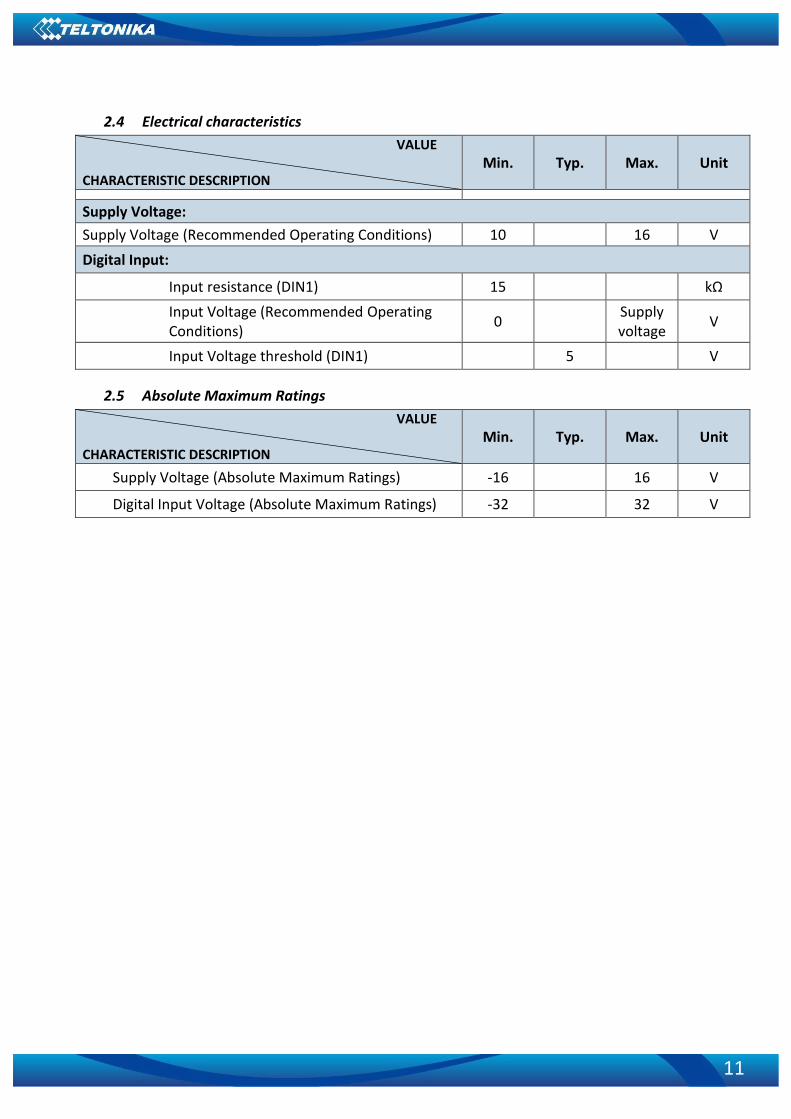
2.4 Electrical characteristics
VALUE
CHARACTERISTIC DESCRIPTION Min. Typ. Max. Unit
Supply Voltage:
Supply Voltage (Recommended Operating Conditions) 10 16 V
Digital Input:
Input resistance (DIN1) 15 kΩ
Input Voltage (Recommended Operating Conditions)
0 Supply voltage
V
Input Voltage threshold (DIN1) 5 V
2.5 Absolute Maximum Ratings
VALUE
CHARACTERISTIC DESCRIPTION Min. Typ. Max. Unit
Supply Voltage (Absolute Maximum Ratings) -16 16 V
Digital Input Voltage (Absolute Maximum Ratings) -32 32 V
12
3 CONNECTION, PINOUT, ACCESSORIES
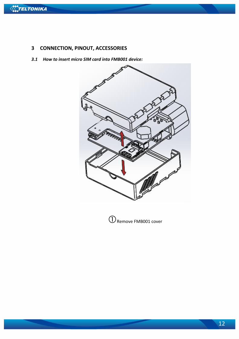
3.1 How to insert micro SIM card into FMB001 device:
Remove FMB001 cover

13
Insert micro SIM card as shown (bottom
slot)
Insert SD card as shown (top slot)
Attach cover Device is ready

14
3.2 Installing FMB001 drivers
Software requirements:
• Operating system 32-bit and 64-bit: Windows XP with SP3 or later, Windows Vista, Windows 7. • MS .NET Framework V3.5 or later (http://www.microsoft.com or http://avl1.teltonika.lt/downloads/tavl/Framework/dotnetfx35setupSP1.zip).
Drivers:
Please download MediaTek inbox COM Port drivers from Teltonika website: http://avl1.teltonika.lt/downloads/FMB0/MS_USB_ComPort_Driver_exe_v1.1032.3.zip
Installing drivers:
Extract and run FP_INBOX_InstallDriver_v1.1032.3.exe. This driver is used to detect FMB001 device connected to the computer. Click 'Next' in driver installation window (figures below):
Figure 2 Driver installation window
This will launch device driver installation wizard. In the following window click ‘Install’
button:
Figure 3 Driver installation window
15
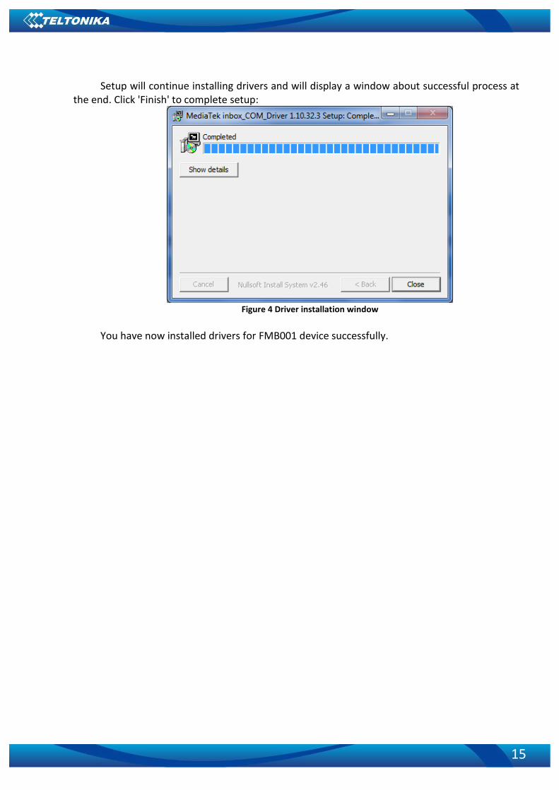
Setup will continue installing drivers and will display a window about successful process at the end. Click 'Finish' to complete setup:
Figure 4 Driver installation window
You have now installed drivers for FMB001 device successfully.

16
3.3 OBD II
Figure 5 OBD II pinout
Pin Nr.
Pin Name Description
1 Ignition input
2 PWM_BUS+/VPW
3 -
4 GND (-) Ground pin.
5 GND (-) Ground pin.
6 CAN_H
7 K-Line
8 -
9 -
10 PWM_BUS-
11 -
12 -
13 -
14 CAN_L
15 L-Line
16 Power +(1016) V DC Power range +(10...16) V DC to ground Table 3 FMB001 pinout description

17
3.4 Navigate LED
3.5 Status LED
Behavior Meaning Blinking every second Normal mode
Blinking every 2 seconds Deep sleep mode
Blinking fast for a short time Modem activity
Blinking fast constantly Boot mode
Off Device is not working Or
Device firmware being flashed
4 OPERATIONAL BASICS
4.1 Operational principals
FMB001 module is designed to acquire records and send them to the server. Records contain GNSS data and I/O information. Module uses GNSS receiver to acquire GNSS data and is powered with three data acquiring methods: time-based, distance-based and angle-based. Note, that if FMB001 loses connection to GNSS satellites, it continues to make records, however coordinate in these records remains the same (last known coordinate). All data is stored in flash memory and later can be sent via GPRS.
GPRS and SMS settings are described in later sections. FMB001 communicates with server using special data protocol.
FMB001 can be managed by SMS commands. SMS Command list is described in SMS COMMAND LIST section. Module configuration can be performed only via SMS.
4.2 Sleep mode
FMB001 is able to go to sleep mode if such mode is enabled. This timeout (defined period) starts counting when device is in STOP mode. After timeout
is reached and all conditions for sleep mode are met, device goes to sleep mode. While in sleep mode, FMB001 turns GPS module off and it is still making new periodic records. As a result power usage decreases, in turn saving vehicle battery.
FMB001 can enter sleep mode if ALL of these conditions are met:
FMB001 has to be configured to work in Sleep mode and start sleep timeout is reached;
Device must have synchronized time with GNSS satellites;
No movement by movement sensor is detected;
Behavior Meaning Permanently switched on GNSS signal is not received
Blinking every second Normal mode, GNSS is working
Off GNSS is turned off because:
Deep sleep mode Or
GNSS antenna short circuited

18
Ignition (configured Ignition Source) is off. FMB001 exits sleep mode when if ONE of following conditions are true:
Movement by movement sensor is detected;
Ignition (configured Ignition Source) is turned on.
4.3 Virtual odometer
Virtual odometer is used to calculate traveled distance in FMB001 as a separate I/O element. When FMB001 detects movement, it starts counting distance using GNSS signal: every second it checks current location and calculates distance between current and previous point. It keeps adding these intervals until it is time to make a record, then FMB001 records its location and adds odometer value, which is equal to the sum of all distances, measured every second. User can choose Odometer mode: 0 – Normal mode, or 1 – Continuous.
At Normal mode, when record is made, odometer resets to zero and distance calculation starts all over again.
Continuous odometer mode requires ignition (configured Ignition source) to be turned on. Odometer counts all distance calculations from records and sums them to one distance. Continuous odometer stops counting, when vehicle is at stop and ignition is turned off.
Figure 6 Odometer continuous and Not continuous distance counting parameter example
4.4 Features
Using available features can greatly increase FMB001 usability options.
4.4.1 Green Driving Scenario.
Helps to prevent and inspect driver about harsh driving. Scenario continuously monitors: accelerating force, braking force and cornering angles.

19
To prevent generating false events, harsh acceleration and harsh braking is monitored only when following conditions are fulfilled:
Ignition is ON (DIN1 = 1)
Vehicle speed is equal or higher than 10km/h Harsh cornering is monitored only when following conditions are fulfilled:
Ignition is ON (DIN1 = 1)
Vehicle speed is equal or higher than 30km/h
Note: Green Driving Scenario is a factor on various cars and various drivers testing phase and can be subject to changes. Teltonika is constantly working on improvement of the functionality of the devices, and strongly recommends using the latest version of the firmware.
4.4.2 Over Speeding Scenario.
Helps to prevent from exceeding fixed speed.
4.4.3 Jamming detection
Jamming detection shows when GSM signal jamming occurs.
4.4.4 Trip
Trip customizable feature enables user extended monitoring of performed trips (from engine start at present location to engine stop at arrived location), log their start and stop points, view driven total distance3.
Note: Scenarios and Trip feature are activated only if DIN1=1 (ignition is on).
4.5 Accelerometer scenarios
4.5.1 Towing Detection
Towing detection scenario helps to inform driver about car deporting. FMB001 generates event when car is being towed or raised, for example in case of vehicle evacuation.
FMB001 activates towing function when these conditions are met: • Ignition (configured Ignition Source) is OFF • Activation Timeout (set in Towing detection features) is reached When Activation Timeout is reached and Ignition is still in OFF state, FMB001 monitors
accelerometer data. If Acceleration or Angle value reaches configured threshold for configured
3 Continuous odometer – total driven distance, works only in TRIP mode. Continues distance is counted only
for ONE trip. If trip is finnished (stop point is detected), odometer resets to 0 (zero). Next trip will start counting from the begining.

20
Duration (in ms), check Ignition state. If Ignition is still OFF during configured "Ignition check after Event Timeout" time, then event is generated. If configured - sends sms event or makes a call.
Function will be reactivated after FMB001 again detects change of Ignition state from ON to OFF.
4.5.2 Unplug Detection
Unplug detection Scenario generates event when FMB001 is unplugged from OBD socket.
4.5.3 Crash Detection
If Crash detection is enabled, it monitors acceleration on each axis, if acceleration exceeds configured value for longer then configured duration, event with value “1” is generated. 4.5.3.1 Crash Trace operation
If trace is enabled FMB will collect acceleration data every 40 msec.
5 CONFIGURATION
5.1 Configurator
New FMB001 module has default factory settings. Settings should be changed according to your application and your GSM operator information.
FMB001 configuration may be performed via SMS commands or configurator. FMB001 has one user editable profile. It can be configured to acquire and send data to server. If device is not able to send data to
server, GSM is not available FMB001 will start storing records to flash memory. It is possible to store up to 122880 data records with 64mb SD memory card. It will send data later when GPRS is available again. Note that FMB001 can have memory full of records. In such case it will start deleting oldest records in order to save new ones. Sending all data records to server may take some time.
FMB001 configuration is performed via FMB001 Configurator program. Contact sales manager to get the latest FMB001 Configurator version. FMB001 configurator operates on Microsoft Windows OS and uses MS .Net Framework 3.5 or higher. Please ensure that MS .Net Framework 3.5 or later is installed on your PC before starting configurator. Latest MS .Net Framework version can be downloaded from official Microsoft web page.
Module configuration is performed over USB cable or BlueTooth connection. Configuration process starts from starting FMB001 Configurator program and then connecting to FMB001 device via Connect button located in Online menu part. FMB001 has one user editable profile, which can be loaded from device, and saved. User can also revert to default settings, by pressing Reset to defaults button. After any modification of configuration settings it has to be saved to FMB001 device, otherwise it will not be written to device.

21
Figure 8 Configurator main window
Main Buttons description: ‘Scan’ – scans for available devices. ‘Connect to device’ – connects device. ‘Store configuration to file’ – saves configuration. ‘Read configuration from file’ – loads saved configuration. ‘Read configuration’ – loads configuration from device. ‘Store configuration’ – saves configuration to device.
5.1.1 System settings
System settings 9 configurable parameters: 1. Sleep settings, where user can choose sleep mode; 2. Ignition source, where user can choose between power voltage, digital input 1 and
accelerometer ignition sources

22
3. Object Motion Detection Settings, where user can configure 3 ways how FMB001 will detect stopped movement, and change its working mode (for working modes, read section 5.1.8);
4. Static navigation settings, where user can turn static navigation on or off; 5. Records Settings, where user can enable or disable records when GPS is not
available (no time synchronization); 6. GNSS source Settings, where user can choose satellite system. 7. LED indication, where user can turn on or off indication LEDs. 8. Battery charge mode, where user can choose when battery charger is turned on. 9. Time synchronization mode, where you can choose how time synchronization is
done. Possible values: a) Disable (GPS only) – time is synchronized only from GNSS satellites b) NITZ – time is synchronized from GNSS satellites or GSM operator (not all GSM
operators support this functionality) c) NTP – time is synchronized from GNSS satellites or NTP servers. d) NITZ+NTP – time can be synchronized from GNSS satellites, GSM operator or
NTP server
Figure 6
If necessary, you can configure your NTP servers and how often device should resynchronize time from NTP (NTP Resync parameter).
Table 5 Configuration parameters
Movement Source Vehicle on Stop mode Vehicle Moving mode
Ignition (recommended)
If ignition (DIN1) is logic low If ignition (DIN1) is logic high
Movement (movement sensor)
Internal movement sensor does not detect movement
Internal movement sensor detects movement
GPS
GPS fix is available and vehicle speed is lower than 5 km/h
GPS fix is available and vehicle speed is higher than 5 km/h
While GPS fix is unavailable, Object Motion Detection Settings are working like in Msensor mode
Static Navigation Mode is a filter, which filters out track jumps when the object is
stationary. If Static navigation filter is disabled, it will apply no changes on GPS data. If Static navigation filter is enabled, it will filter changes in GPS position if no movement is detected

23
(depends on Object Motion Detection Settings). It allows filtering GPS jumps when object is parked (is not moving) and GPS position is still traced.
Figure 9 System settings configuration
In GNSS source Settings user can configure which GNSS system or systems to use. User has choice to use only one system of GPS, Glonass, Galileo or Beidou. Also it is able to
choose two or three systems together. One exception is that you can not combine Beidou and Glonass systems together.
List of configurable GNSS sources: Beidou only ID:01 Glonass only ID:02 Galileo only ID:04

24
Galileo+Beidou ID:05 Galileo+Glonass ID:06 Example of a good configuration Gps only ID:08 Gps+Beidou ID:09 Gos+Glonass ID:10 Gps+Galileo ID:12 Gps+Galileo+Beidou ID:13 Gps+Galileo+Glonass ID:14 List of NON–configurable GNSS sources: Glonass+Beidou Galileo+Glonass+Beidou Gos+Glonass+Beidou GPS+Galileo+Glonass+Beidou Example of a bad configuration
5.1.2 Records settings
Here user can modify if FMB001 device will send newest records first, meaning, that the most important thing is to know recent position of car, older records are being sent right after newest records arrive to AVL application.
Activate Data Link Timeout is used to set timeout of link between FMB001 and AVL application termination. If FMB001 has already sent all records it waits for new records before closing link. If new records are generated in the period of this timeout, and minimum count to send is reached, they are sent to AVL application. This option is useful when GSM operator charge for link activation.
Server Response Timeout is used to set time period waiting for response from server side.
Figure 10 Records settings configuration

25
5.1.3 GSM settings, GPRS part
‘GPRS’ defines main parameters for FMB001: GSM operator APN and GPRS username and password (optional – depending on operator), destination server IP and port, and allows to set protocol used for data transfers – TCP or UDP.
Some operators use specific authentication for GPRS session – CHAP or PAP. If any of these is used, APN should be entered as ‘chap:<APN>’ or ‘pap:<APN>’. I.e. if operator is using APN ‘internet’ with CHAP authentication, it should be entered as ‘chap:internet’. Information about APN and authentication type should be provided by your GSM operator.
Figure 11 GPRS configuration

26
5.1.4 GSM settings, SMS part
Essential fields in ‘SMS’ part are ‘Login’ and ‘Password’. The login and password are used with every SMS sent to FMB001. If login and password are not set, in every SMS sent to FMB001 device two spaces before command have to be used (<space><space><command>).
Command structure with set login and password: <login><space><password><space><command>, example: “asd 123 getgps” Phone numbers have to be written in international standard, without using “+” or “00”
signs in prefix. If no numbers are entered, configuration and sending commands over SMS are allowed from all GSM numbers.
SMS data sending settings – enable or disable periodic data and event SMS usage. This setting does not affect replies to SMS request messages – answers are always sent back to sender telephone number.
Figure 12 SMS configuration
27
5.1.5 SMS Event Time Zones
FMB001 works with synchronized GPS time which is UTC+0, with this option customer can configure his time zone and get SMS with correct time.
Note: Please do not set Data Send Number to some cell phone number, because it will not understand binary SMS. When sending a binary SMS to a phone number, which is a server phone number, the server can interpret and understand binary code, so the data can be read and you can view it on the server.
SMS login and password and authorized number list are used to protect FMB001 module from unauthorized access. Module accepts messages only from a list of authorized numbers and with proper module login and password. Numbers must be without “+” or “00” prefix. If no authorized numbers are entered, module accepts messages from all numbers.
5.1.6 SMS events
SMS events functionality allows FMB001 to send a configured SMS when an event is triggered. This event can be triggered by ever I/O element.
Then any of the I/O elements is triggered, FMB001 sends a configured SMS message to a defined phone number. If SMS events is activated, but there are no numbers defined in SMS events PreDefined Numbers list (figure 20), then the device will not send any messages.

28
Figure 20 SMS Events PreDefined Numbers list
The sent SMS messages format is according to:
“Date Time EventText”
For example, if FMB001 is configured to send an SMS, when Ignition reaches High level, with priority High and configured to generate event on both, range enter and exit (figure 21), then the sent SMS is: “2012/6/7 12:00:00 Ignition 1”

29
Figure 21 Configured Ignition SMS event
The SMS Text field can be altered and any text can be entered. Maximum message length is
90 symbols (numbers, letters and symbols in ASCII, except for comma “,”).
ATTENTION! If FMB001 is in Deep Sleep mode and SMS event occurs with LOW priority (which does not wake up FMB001), then the device does not send the message. It is saved in device memory until it wakes up from Deep Sleep mode and GSM modem starts working normally. After it wakes up, all the messages that are saved in memory will be sent, but keep in mind that only 10 messages can be saved in memory – all other messages will not be saved, until there is room in device memory.
5.1.7 GSM settings, Operator list
Operators list – FMB001 can work in different modes (use different settings) according to the operator list defined. Operator list is used for Data Acquisition Mode switching (see chapter 5.1.8 Data Acquisition Mode settings for more details). Modes are changed based on GSM operator FMB001 is connected to.

30
Figure 13 Operator list configuration
If operator list is left empty, it will allow using GPRS to any GSM operator. Please note that
FMB001 will work in Unknown mode only (make sure it is configured to allow data sending – GPRS context is enabled).
5.1.8 Features settings
In Features window five different scenarios are available.
31
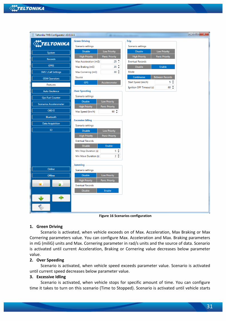
Figure 16 Scenarios configuration
1. Green Driving
Scenario is activated, when vehicle exceeds on of Max. Acceleration, Max Braking or Max Cornering parameters value. You can configure Max. Acceleration and Max. Braking parameters in mG (miliG) units and Max. Cornering parameter in rad/s units and the source of data. Scenario is activated until current Acceleration, Braking or Cornering value decreases below parameter value. 2. Over Speeding
Scenario is activated, when vehicle speed exceeds parameter value. Scenario is activated until current speed decreases below parameter value. 3. Excessive Idling
Scenario is activated, when vehicle stops for specific amount of time. You can configure time it takes to turn on this scenario (Time to Stopped). Scenario is activated until vehicle starts

32
moving and keeps moving for amount of time that is configured. You can configure time it takes to turn OFF this scenario (Time to Stopped). 4. Jamming
Scenario is activated, when jamming is detected. 5. Trip
Scenario is activated, when ignition is on and movement is detected. Scenario calculates distance user has moved.
5.1.9 Trip settings
Trip scenario offers user to configure Trip feature. Start Speed – GPS speed has to be greater than the specified Start Speed in order to detect
Trip Start. Ignition Off Timeout – timeout to wait if ignition was off, to detect Trip stop. Continuous distance counting – Not or Continuous can be chosen. For this feature I/O
Odometer must be enabled. If I/O Odometer is enabled and Continuous distance counting variable (Mode) is set to
Continuous, Trip distance is going to be counted continuously (from Trip start to Trip stop). This value is written to I/O Odometer value field. When Trip is over and next Trip begins, Odometer value is reset to zero. When the next trip starts counting continuously starts from the beginning again.
If I/O Odometer is enabled and Continuous Distance Counting variable (Mode) is set “Between Records”, then the distance is going to be counted only between every record made. This value is written to I/O Odometer value field and reset to zero every new record until Trip stops. If later all Odometer values are summed up manually, the user gets the distance driven during the whole period of the Trip.
Figure 17 Trip configuration

33
Figure 18 Trip continuous distance counting parameter example
5.1.10 AutoGeofencing settings
AutoGeofence – the last known position after movement = off. If your car’s being taken away – you can be notified. The shape and size of the geofence zones are parameters. It is possibility to state whether entering in or out of the geofence triggers an asynchronous message.
AutoGeofencing option can be configured by following parameters visible in figure 19 below.
Activation TMO – Time period before Geofence is activated after vehicle stops. Deactivate By:
Ignition – If ignition becomes high it will disable AutoGeofenze Zone; Power Voltage – if power voltage enters entered value it will disable AutoGeofenze
Zone. Digital input 1 – if digital input is triggered it will disable AutoGeofenze Zone.
Feature – Priority of generated event, which will be applied to saved record. Enter Event – Event generation on Geofence entrance. Exit Event – Event generation on Geofence exit. On Both - Event generation on Geofence entrance Or exit Eventual Records – Enable or Disable Eventual Records functionality.
Note that AutoGeofencing does not require entering coordinates, instead it requires GPS
visibility. If vehicle stopped and activation timeout has passed, an AutoGeofence will be created around vehicle’s last position with set Radius value.

34
Figure 19 Geofence configuration
5.1.11 GPS Fuel Counter
Configuration of Fuel Consumption (Figure 7) 1. To configure these parameters use fuel consumption data, which is stated in your car
technical documentation. By default speeds for this fuel consumption norms are: City – 30 km/h, Average – 60 km/h, Highway - 90 km/h. If you want, you can change it.
2. When speed is higher than highway speed, FMB001 adds highway fuel consumption x % of highway fuel consumption every y km/h, by default FMB001 adds 20% every 50 km/h. It

35
means that fuel consumption is (1.2 * Highway Fuel Consumption) on 140 km/h speed, (1.4 * Highway Fuel Consumption) on 190 km/h speed.
3. Correction coefficient is used for correction of every fuel consumption value which is sent to server (Used Fuel * Correction coefficient). By default it is 1, min 0.01 and max 2. For example when correction coefficient is 1 and FMB001 calculates that used fuel for 35 m distance is 20 ml, sent value will be 20 ml; if correction coefficient is 1.2, sent value will be 20 * 1.2 = 24 ml.
4. Fuel consumption on idling is used to calculate fuel consumption when ignition is on, but vehicle speed is 0 km/h. By default it is 1 l/h, min 0 and max 5 l/h. Almost in all diesel cars this parameter is less than 1.0 l/h. In gasoline cars this parameter is about 1.5 – 2.0 l/h.
Figure 7 GPS fuel counter settings
When ignition is on, device starts calculating fuel consumption. When GPS speed is 0, used fuel is calculated l/h. When device is moving FMB001 gets speed value every second from satellites and according to this speed calculation of fuel consumption is done. Device takes travelled distance of this period to calculate used fuel in ml, and sends this value to server, parameter Used fuel (ml) calculated by GPS. Also parameter AVG fuel consumption (l/100km) is sent, which is calculated by GPS (this parameter is sent multiplied by 100).
Both parameters are calculated from the moment when device powers on for the first time. If you want to reset “Used fuel (ml) calculated by GPS” and “AVG fuel consumption (l/100km) calculated by GPS” parameters, you need to send SMS command “fc_reset”. If GNSS fix was lost FMB001 uses average fuel consumption setting to calculate used fuel for range without GNSS fix.
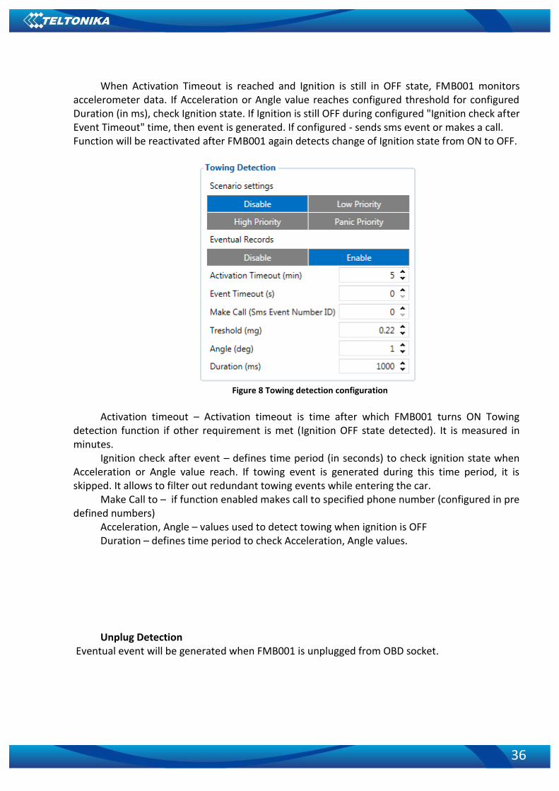
5.1.12 Scenarios Accelerometer
Towing detection FMB001 activates towing function when these conditions are met:
Ignition (configured Ignition Source) is OFF
Activation Timeout (set in Towing detection features) is reached
36
When Activation Timeout is reached and Ignition is still in OFF state, FMB001 monitors accelerometer data. If Acceleration or Angle value reaches configured threshold for configured Duration (in ms), check Ignition state. If Ignition is still OFF during configured "Ignition check after Event Timeout" time, then event is generated. If configured - sends sms event or makes a call. Function will be reactivated after FMB001 again detects change of Ignition state from ON to OFF.
Figure 8 Towing detection configuration
Activation timeout – Activation timeout is time after which FMB001 turns ON Towing
detection function if other requirement is met (Ignition OFF state detected). It is measured in minutes.
Ignition check after event – defines time period (in seconds) to check ignition state when Acceleration or Angle value reach. If towing event is generated during this time period, it is skipped. It allows to filter out redundant towing events while entering the car.
Make Call to – if function enabled makes call to specified phone number (configured in pre defined numbers)
Acceleration, Angle – values used to detect towing when ignition is OFF Duration – defines time period to check Acceleration, Angle values. Unplug Detection
Eventual event will be generated when FMB001 is unplugged from OBD socket.

37
Figure 9 Unplug detection
Crash detection If Crash detection is enabled, it monitors acceleration on each axis, if acceleration exceeds
configured value for longer then configured duration, event with value “1” is generated.
ID Name Possible values Units
11400 Crash Detection Enable [0/1]
11401 Duration 0 – 2000 ms
11402 Threshold 0 - 7900 mG
11406 Crash Detection Trace Enable [0/1]
11400 Crash Detection Enable [0/1]
Table 4 Configuration parameters
Crash Trace operation If trace is enabled FMB will collect acceleration data every 40 msec. Buffer is big enough to
hold data for 5 seconds and on Crash Event detection, records will be generated from this buffer, following these conditions:
Every second
Acceleration changed more then > 50mG Data will be collected and records generated 5 seconds after the event using the same
conditions. Every generated record will have accelerometer X Y Z values included. Each record will
have accurate timestamps in milliseconds (for detailed crash trace record structure refer to FMB001 protocol document).
Usually between 20 to 30 records is generated on crash event detection.

38
Figure 10 Example of Crash Trace logic
5.1.13 OBD II
Disable/Enable OBD II data reading.

39
5.1.14 Bluetooth
General
Figure 11 General Bluetooth settings
BT Radio determines state determines Bluetooth status, possible values: a) Disable – Bluetooth is off; b) Enable (hidden) – Bluetooth is on, device automatically connects to defined MAC, but is
invisible for external devices which want to pair with it. c) Enable (visible) – Bluetooth is on and visible for external devices.
Local name can be set according to your needs. If this field is empty, name will be
automatically generated: FMBxx_<imei last chars> Local PIN - PIN code which will be used when external device will try to pair with FMB001. Security mode possible options: a) PIN only – only pin is used when external device tries to connect to FMB001. b) PIN+MAC list – PIN is used, also external device’s MAC address needs to be in
Authorized MAC list c) MAC list only – connection to FMB001 is possible only if external device MAC is in
Authorized MAC list. d) None – no security enabled.
Auto Connect to External Device
Figure 12 Auto connection to external devices
Here you can enter details of external Bluetooth headset for hands free communication. External MAC – MAC of your Bluetooth headset.
40
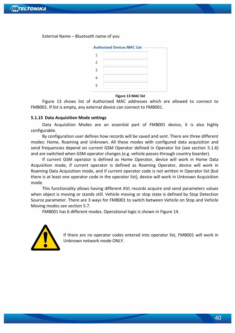
External Name – Bluetooth name of you
Figure 13 MAC list
Figure 13 shows list of Authorized MAC addresses which are allowed to connect to FMB001. If list is empty, any external device can connect to FMB001.
5.1.15 Data Acquisition Mode settings
Data Acquisition Modes are an essential part of FMB001 device, it is also highly configurable.
By configuration user defines how records will be saved and sent. There are three different modes: Home, Roaming and Unknown. All these modes with configured data acquisition and send frequencies depend on current GSM Operator defined in Operator list (see section 5.1.6) and are switched when GSM operator changes (e.g. vehicle passes through country boarder).
If current GSM operator is defined as Home Operator, device will work in Home Data Acquisition mode, if current operator is defined as Roaming Operator, device will work in Roaming Data Acquisition mode, and if current operator code is not written in Operator list (but there is at least one operator code in the operator list), device will work in Unknown Acquisition mode.
This functionality allows having different AVL records acquire and send parameters values when object is moving or stands still. Vehicle moving or stop state is defined by Stop Detection Source parameter. There are 3 ways for FMB001 to switch between Vehicle on Stop and Vehicle Moving modes see section 5.7.
FMB001 has 6 different modes. Operational logic is shown in Figure 14.
If there are no operator codes entered into operator list, FMB001 will work in Unknown network mode ONLY.

41
Figure 14 Data Acquisition Mode configuration
Operator search is performed every 15 minutes. Depending on current GSM operator,
Home, Roaming or Unknown mode can be changed faster than every 15 minutes. This process is separate from operator search. Movement criteria are checked every second.

42
Figure 15 Data Acquisition Mode configuration
‘Min Saved Records’ defines minimum number of coordinates and I/O data that should be
transferred with one connection to server. If FMB001 does not have enough coordinates to send to server, it will check again after time interval defined in ‘Sending Period’.
Send period – GPRS data sending to server period. Module makes attempts to send
collected data to server every defined period. If it does not have enough records (depends on parameter Min. Saved Records described above), it tries again after defined time interval.
Note: Keep in mind that FMB001 operates in GMT: 0 time zone, without daylight saving.

43
FMB001 is able to collect records using four methods at the same time: time, distance,
angle and speed based data acquisition:
Min. time period
Distance based data acquiring (Min. distance) – records are being acquired when the distance between previous coordinate and current position is greater than defined parameter value. Entering zero disables data acquisition depending on distance.
Min. distance
Angle based data acquiring (Min. angle) – records are being acquired when angle difference between last recorded coordinate and current position is greater than defined value. Entering zero disables data acquisition depending on angle.
Min. angle
Speed based data acquiring (Min. Speed Delta) – records are being acquired when speed difference between last recorded coordinate and current position is greater than defined value. Entering zero disables data acquisition depending on speed.
44
5.1.16 Connecting to device via Bluetooth
When FMB device starts, automatically Bluetooth is ON too. Take your mobile phone, go to settings>Bluetooth and turn it on. Scan for near by devices, find you device in list, distinguish device by last IMEI numbers on device module. Press pair, wait until device will ask to enter pairing password, type: 5555. Paired device will show up in paired device list. Now download from play store/app store terminal for Bluetooth. E.g. BlueTerm. Run app, click find>connect to your paired device. Now we need to send command to FMB001 through Bluetooth terminal, type: .log:1
Device will respond Debug enabled and FMB001 log will show up. Do not forget to start save log file to mobile phone.
5.2 OBD functionality description
5.2.1 Supported OBD protocols
1. SAE J1850 PWM (41.6 kbaud); 2. SAE J1850 VPW (10.4 kbaud); 3. ISO 9141-2 (5 baud init, 10.4 kbaud); 4. ISO 14230-4 KWP (5 baud init, 10.4 kbaud); 5. ISO 14230-4 KWP (fast init, 10.4 kbaud); 6. 15765-4 CAN (11 bit ID, 500 kbaud); 7. ISO 15765-4 CAN (29 bit ID, 500 kbaud); 8. ISO 15765-4 CAN (11 bit ID, 250 kbaud); 9. ISO 15765-4 CAN (29 bit ID, 250 kbaud); 10. SAE J1939 CAN (29 bit ID, 250 kbaud).
5.2.2 General info
Functionality supports (CAN and KLINE FAST) protocol, standard pid readout.
5.2.3 Initialization
Functionality initializes automatically, finds proper protocol and communicates using it.
5.2.4 Data
Data is saved as I/O elements. OBD I/O elements must be enabled by configurator. All OBD elements are configured in same logic as other I/O property elements.
5.3 I/O settings
When none of I/O elements are enabled, AVL packet comes with GNSS information only. After enabling I/O element(s) AVL packet along with GNSS information contains current value(s) of enabled I/O element.

45
Enabled or disabled field – allows enabling I/O element so it is added to the data packet and is sent to the server. By default all I/O element are disabled and FMB001 records only GNSS coordinates.
Priority (AVL packet priority) all records made by FMB001 are regular. Regular packets are sent as Low priority records. When low priority event is triggered, FMB001 makes additional record with indication that the reason for that was I/O element change.
Table 6 Permanent I/O elements
Permanent I/O elements (are always sent to server if enabled)
Nr. Property Name Description
1 Ignition Logic: 0 / 1
2 Movement Logic: 0 / 1
3 Data mode 0 – home on stop, 1 – home on move, 2 – roaming on stop, 3 – roaming on move, 4 – unknown on stop, 5 – unknown on move
4 GSM signal GSM signal level value in scale 1 – 5
5 Sleep mode Logic: 0 / 1
6 GNSS Status
States: 0 – short circ., 1 – connected. Parameter defines if GPS antenna is short circuit. All the time value will be sent 1. The only condition to get value 0, then antenna is damaged and short circuit.
7 GNSS PDOP Probability * 10; 0-500
8 GNSS HDOP Probability * 10; 0-500
9 External Voltage Voltage: mV, 0 – 30 V
10 Speed Value in km/h, 0 – xxx km/h
11 GSM Cell ID GSM base station ID
12 GSM Area Code
Location Area code (LAC), it depends on GSM operator. It provides unique number which assigned to a set of base GSM stations. Max value: 65536
13 Battery Voltage Shows battery Voltage in mV
14 Battery Current Shows battery Current in mA
15 Active GSM operator Currently used GSM Operator code
16 Trip odometer Distance between two records: m
17 Total odometer Total odometer count: m
18 Digital Input 1 Logic: 0 / 1
19 Fuel Used GPS Fuel used (ml) by GPS
20 Fuel Rate GPS Fuel Consumption by average speed (l/100km)
21 Axis X Accelerometer axis x value
22 Axis Y Accelerometer axis y value
23 Axis Z Accelerometer axis z value
OBD II Parameters
24 Number Of DTC Diagnostic Trouble Codes
46
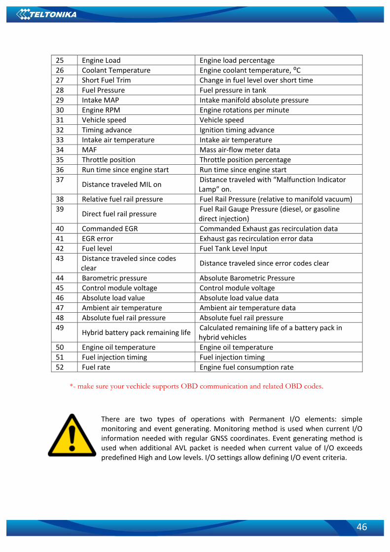
25 Engine Load Engine load percentage
26 Coolant Temperature Engine coolant temperature, ⁰C
27 Short Fuel Trim Change in fuel level over short time
28 Fuel Pressure Fuel pressure in tank
29 Intake MAP Intake manifold absolute pressure
30 Engine RPM Engine rotations per minute
31 Vehicle speed Vehicle speed
32 Timing advance Ignition timing advance
33 Intake air temperature Intake air temperature
34 MAF Mass air-flow meter data
35 Throttle position Throttle position percentage
36 Run time since engine start Run time since engine start
37 Distance traveled MIL on
Distance traveled with “Malfunction Indicator Lamp” on.
38 Relative fuel rail pressure Fuel Rail Pressure (relative to manifold vacuum)
39 Direct fuel rail pressure
Fuel Rail Gauge Pressure (diesel, or gasoline direct injection)
40 Commanded EGR Commanded Exhaust gas recirculation data
41 EGR error Exhaust gas recirculation error data
42 Fuel level Fuel Tank Level Input
43 Distance traveled since codes clear
Distance traveled since error codes clear
44 Barometric pressure Absolute Barometric Pressure
45 Control module voltage Control module voltage
46 Absolute load value Absolute load value data
47 Ambient air temperature Ambient air temperature data
48 Absolute fuel rail pressure Absolute fuel rail pressure
49 Hybrid battery pack remaining life
Calculated remaining life of a battery pack in hybrid vehicles
50 Engine oil temperature Engine oil temperature
51 Fuel injection timing Fuel injection timing
52 Fuel rate Engine fuel consumption rate
*- make sure your vechicle supports OBD communication and related OBD codes.
There are two types of operations with Permanent I/O elements: simple monitoring and event generating. Monitoring method is used when current I/O information needed with regular GNSS coordinates. Event generating method is used when additional AVL packet is needed when current value of I/O exceeds predefined High and Low levels. I/O settings allow defining I/O event criteria.

47
6 SMS COMMAND LIST
All commands are case sensitive. While FMB001 operates in Sleep mode and user tries to send SMS message it will arrive to FMB001 device, because GSM module is enabled. Only GNSS module is disabled in sleep mode.
6.1 SMS command list
Table 4 SMS commands
Command Description Response
getinfo Returns RTC time, GPS status, SAT Yes
getver Returns code version, device IMEI, modem app version, RTC time
Yes
getstatus Returns Data Link:0 GPRS:0 Phone:0 SIM:0 OP:24602 Signal:5 NewSMS:0 Roaming:0 SMSFull:0 LAC:0 Cell ID: 0
Yes
getgps Returns GPS status, Satellite number, Latitude, Longitude, Altitude, Speed, Date, Time
Yes
ggps Returns location information with Google maps link Yes
readio Returns IO status Yes
cpureset Resets device No
getparam Returns selected parameter value Yes
setparam Sets selected parameter value Yes
flush Redirects device to other server Yes
countrecs Returns record number Yes
setdigout X,Y Set digital output X – 0 or 1 (0 - OFF or 1 – ON) Y – timeout value if needed (in seconds)
Yes
fc_reset Resets fuel consumption parameters Yes
towingreact Towing reactivation Yes btgetlist Returns requested Bluetooth list(values:0, 1, 2) Yes btgscan Starts Bluetooth scan(values: none, 1) Yes btvisible Sets Bluetooth to visible with TMO Yes btrelease Disconnects from current device and pauses auto connect
functionality for TMO Yes
btunpair Unpair Bluetooth device Yes
Setparam and setdigout SMS is used to configure device. Parameter ID consists of 3 or 5 digits. Detailed list of parameters and IDs can be found in
chapter number 5.2 “System parameters” Example: ‘username password setparam 102:0’ will disable sleep mode. Example: ‘username password setdigout 1 60’ will set digital output ON for 60s.

48
6.1.1 getinfo
Response details Description
RTC RTC Time
GPS GPS receiver state. 0 – OFF, 1 – restarting, 2 – ON but no fix, 3 –ON and operational, 4 – sleep mode
SAT Average satellites Example: RTC:2017/1/9 14:13 GPS:1 SAT:0
6.1.2 getver
Response details Description
App Ver Firmware version
Modem Ver Version of modem application
GPS Ver Version of GPS module
Hw Ver Version of hardware
Device IMEI IMEI Example: App Ver:01.00.17 Rev:01 Modem Ver:TM25Q_D_01.00.00.00_010 GPS
Ver:AXN_3.82_3333_1Hw Ver:FMB9_MOD2_A0:B0:C1:D0 Device IMEI:352094080000950
6.1.3 getstatus
Response details Description
Data Link Indicate module connection to server at the moment: 0 – Not connected, 1 – connected
GPRS Indicate if GPRS is available at the moment
Phone Voice Call status: 0 – ready, 1 – unavailable, 2 – unknown, 3 –ringing, 4 – call in progress, 5 – asleep
SIM SIM Status: 0-ready, 1-pin, 2-puk, 3-pin2, 4-puk2
OP Connected to GSM Operator: numerical id of operator
Signal GSM Signal Quality [0-5]
NewSMS Indicate if new message received
Roaming 0 – Home Network, 1 – roaming
SMSFull SMS storage is full? 0 – ok, 1 – SMS storage full
LAC GSM Tower Location Area Code
Cell ID GSM Tower Cell ID Code Example: Data Link: 0 GPRS: 1 Phone: 0 SIM: 0 OP: 24602 Signal: 5 NewSMS: 0 Roaming: 0
SMSFull: 0 LAC: 1 Cell ID: 3055
6.1.4 getgps
Response details Description
GPS Indicates valid (1) or invalid (0) Gps data
Sat Count of currently available satellites
Lat Latitude (Last good Latitude)

49
Long Longitude (Last good Longitude)
Alt Altitude
Speed Ground speed, km/h
Dir Ground direction, degrees
Date Current date
Time Current GMT time Example: GPS:1 Sat:0 Lat:54.666042 Long:25.225031 Alt:0 Speed:0 Dir:0 Date: 17/1/9 Time:
12:52:30
6.1.5 ggps
Response details Description
D Date
T Time
S Actual Speed
C Latitude (Last good Latitude), Longitude (Last good Longitude)
Url Google Maps Link Example: D:17/1/9 T:12:52:30 S:0.00 C:54.666042, 25.225032 Url:
http://maps.google.com/?q=54.666042,25.225032&om=1speed:0
6.1.6 readio #
Response details Description
ID I/O element ID
Value I/O Element value Example: Param ID:3 Value:0
6.1.7 getparam
Read parameter value. ID consists of 3 or 4 digits. Detailed list of parameters and IDs can be found in chapter number 8 “Parameter List”
Example: ‚getparam 2001‘ command will request APN name Answer: Param ID:2001 Value:wap
6.1.8 setparam
Sets new value for parameter. ID consists of 3 or 4 digits. Detailed list of parameters and IDs can be found in chapter number 8 “Parameter List”
Example: ‚setparam 2001 wap2‘ will change configured APN name Answer: Param ID:2001 Value:wap2
6.1.9 flush #,#,#,#,#,#,#
Initiates all data sending by GPRS to specified target server. Comma separated parameters
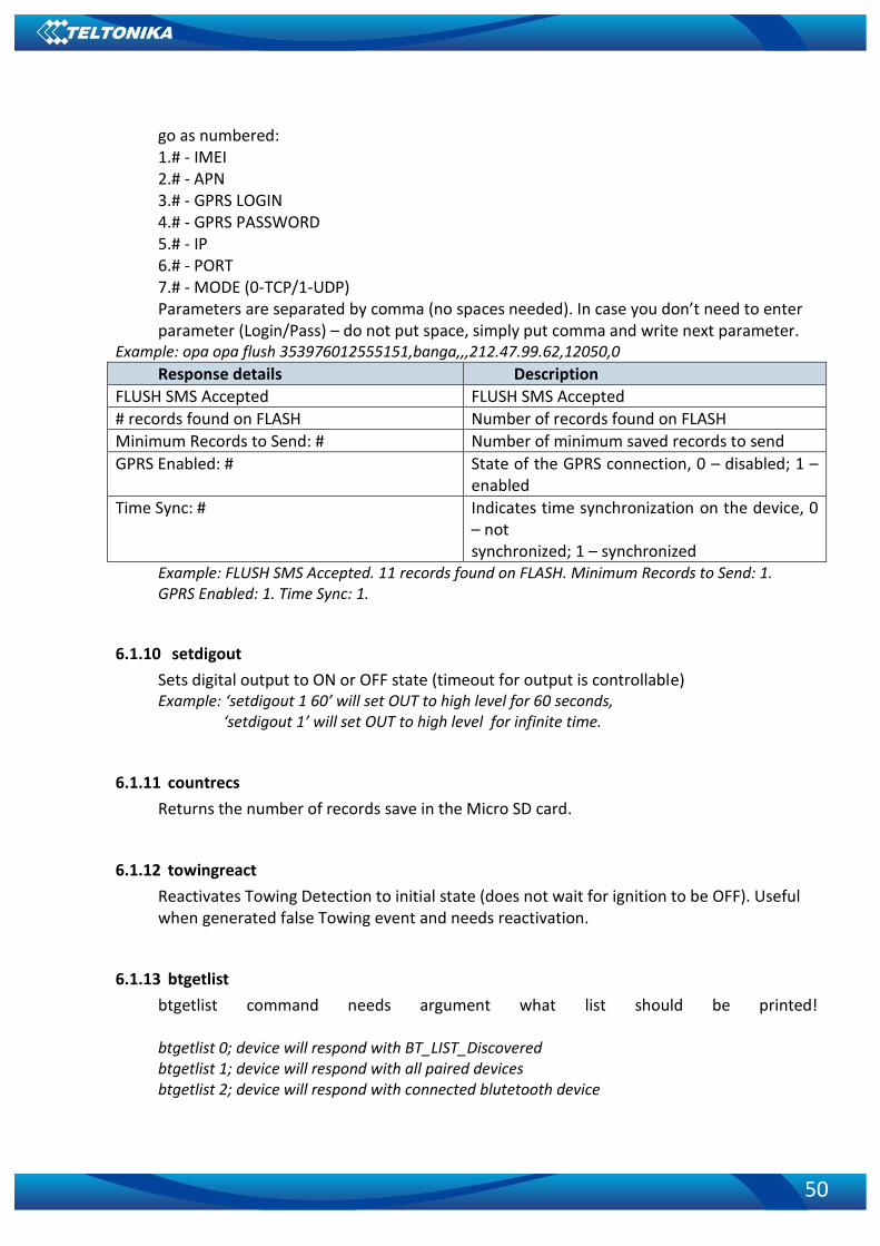
50
go as numbered: 1.# - IMEI 2.# - APN 3.# - GPRS LOGIN 4.# - GPRS PASSWORD 5.# - IP 6.# - PORT 7.# - MODE (0-TCP/1-UDP) Parameters are separated by comma (no spaces needed). In case you don’t need to enter parameter (Login/Pass) – do not put space, simply put comma and write next parameter.
Example: opa opa flush 353976012555151,banga,,,212.47.99.62,12050,0
Response details Description
FLUSH SMS Accepted FLUSH SMS Accepted
# records found on FLASH Number of records found on FLASH
Minimum Records to Send: # Number of minimum saved records to send
GPRS Enabled: # State of the GPRS connection, 0 – disabled; 1 – enabled
Time Sync: # Indicates time synchronization on the device, 0 – not synchronized; 1 – synchronized
Example: FLUSH SMS Accepted. 11 records found on FLASH. Minimum Records to Send: 1. GPRS Enabled: 1. Time Sync: 1.
6.1.10 setdigout
Sets digital output to ON or OFF state (timeout for output is controllable) Example: ‘setdigout 1 60’ will set OUT to high level for 60 seconds, ‘setdigout 1’ will set OUT to high level for infinite time.
6.1.11 countrecs
Returns the number of records save in the Micro SD card.
6.1.12 towingreact
Reactivates Towing Detection to initial state (does not wait for ignition to be OFF). Useful when generated false Towing event and needs reactivation.
6.1.13 btgetlist
btgetlist command needs argument what list should be printed! btgetlist 0; device will respond with BT_LIST_Discovered btgetlist 1; device will respond with all paired devices btgetlist 2; device will respond with connected blutetooth device
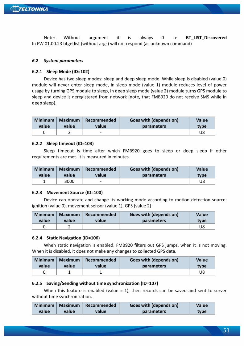
51
Note: Without argument it is always 0 i.e BT_LIST_Discovered In FW 01.00.23 btgetlist (without args) will not respond (as unknown command)
6.2 System parameters
6.2.1 Sleep Mode (ID=102)
Device has two sleep modes: sleep and deep sleep mode. While sleep is disabled (value 0) module will never enter sleep mode, in sleep mode (value 1) module reduces level of power usage by turning GPS module to sleep, in deep sleep mode (value 2) module turns GPS module to sleep and device is deregistered from network (note, that FMB920 do not receive SMS while in deep sleep).
Minimum value
Maximum value
Recommended value
Goes with (depends on) parameters
Value type
0 2 - U8
6.2.2 Sleep timeout (ID=103)
Sleep timeout is time after which FMB920 goes to sleep or deep sleep if other requirements are met. It is measured in minutes.
Minimum value
Maximum value
Recommended value
Goes with (depends on) parameters
Value type
1 3000 - U8
6.2.3 Movement Source (ID=100)
Device can operate and change its working mode according to motion detection source: ignition (value 0), movement sensor (value 1), GPS (value 2)
Minimum value
Maximum value
Recommended value
Goes with (depends on) parameters
Value type
0 2 - U8
6.2.4 Static Navigation (ID=106)
When static navigation is enabled, FMB920 filters out GPS jumps, when it is not moving. When it is disabled, it does not make any changes to collected GPS data.
Minimum value
Maximum value
Recommended value
Goes with (depends on) parameters
Value type
0 1 1 U8
6.2.5 Saving/Sending without time synchronization (ID=107)
When this feature is enabled (value = 1), then records can be saved and sent to server without time synchronization.
Minimum value
Maximum value
Recommended value
Goes with (depends on) parameters
Value type

52
0 1 1 U8
6.2.6 GNSS Source (ID=109)
This parameter sets Satellite System, available values: Beidou only value:1 Glonass only value:2 Galileo only value:4 Galileo+Beidou value:5 Galileo+Glonass value:6 Gps only value:8 Gps+Beidou value:9 Gos+Glonass value:10 Gps+Galileo value:12 Gps+Galileo+Beidou value:13 Gps+Galileo+Glonass value:14
Minimum value
Maximum value
Recommended value
Goes with (depends on) parameters
Value type
0 14 - U8
6.2.7 Ignition settings (ID=101)
This parameter sets ignition source available values : 0 – Power voltage, 1 – Digital Input, 2– Accelerometer.
Minimum value
Maximum value
Recommended value
Goes with (depends on) parameters
Value type
0 2 0 U8
6.2.8 High voltage level (ID=104)
Sets high level of voltage if ignition settings is set to power voltage.
Minimum value
Maximum value
Recommended value
Goes with (depends on) parameters
Value type
0 30000 30000 U8
6.2.9 Low voltage level (ID=105)
Sets low level of voltage if ignition settings is set to power voltage.
Minimum value
Maximum value
Recommended value
Goes with (depends on) parameters
Value type
0 29999 13000 U8
6.2.10 Led indication (ID=108)
Sets led indication: 0 – disabled, 1 – enabled
Minimum Maximum Recommended Goes with (depends on) Value
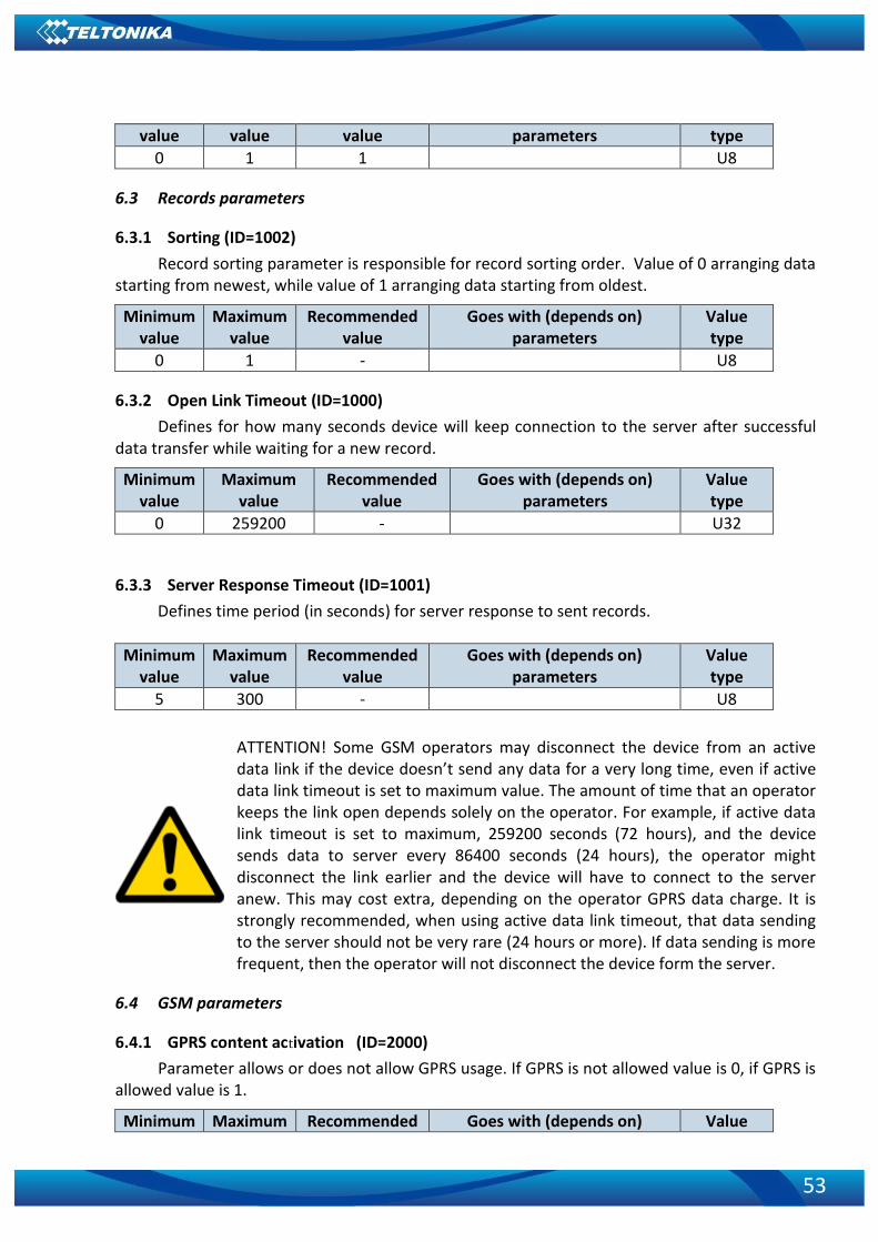
53
value value value parameters type
0 1 1 U8
6.3 Records parameters
6.3.1 Sorting (ID=1002)
Record sorting parameter is responsible for record sorting order. Value of 0 arranging data starting from newest, while value of 1 arranging data starting from oldest.
Minimum value
Maximum value
Recommended value
Goes with (depends on) parameters
Value type
0 1 - U8
6.3.2 Open Link Timeout (ID=1000)
Defines for how many seconds device will keep connection to the server after successful data transfer while waiting for a new record.
Minimum value
Maximum value
Recommended value
Goes with (depends on) parameters
Value type
0 259200 - U32
6.3.3 Server Response Timeout (ID=1001)
Defines time period (in seconds) for server response to sent records.
Minimum value
Maximum value
Recommended value
Goes with (depends on) parameters
Value type
5 300 - U8
ATTENTION! Some GSM operators may disconnect the device from an active data link if the device doesn’t send any data for a very long time, even if active data link timeout is set to maximum value. The amount of time that an operator keeps the link open depends solely on the operator. For example, if active data link timeout is set to maximum, 259200 seconds (72 hours), and the device sends data to server every 86400 seconds (24 hours), the operator might disconnect the link earlier and the device will have to connect to the server anew. This may cost extra, depending on the operator GPRS data charge. It is strongly recommended, when using active data link timeout, that data sending to the server should not be very rare (24 hours or more). If data sending is more frequent, then the operator will not disconnect the device form the server.
6.4 GSM parameters
6.4.1 GPRS content activation (ID=2000)
Parameter allows or does not allow GPRS usage. If GPRS is not allowed value is 0, if GPRS is allowed value is 1.
Minimum Maximum Recommended Goes with (depends on) Value

54
value value value parameters type
0 1 - 6.4.2 APN Name (ID=2001)
APN username (ID=2002) APN Password (ID=2003)
S8
6.4.3 APN Name (ID=2001)
Parameter defines GPRS Access Point Name.
Minimum value
Maximum value
Recommended value
Goes with (depends on) parameters
Value type
Empty 32 char string
-
GPRS content activation (ID=2000)
APN username (ID=2002) APN Password (ID=2003)
S8[32]
6.4.4 APN username (ID=2002)
Parameter defines APN username. In case operator does not use username for login, value should be empty.
Minimum value
Maximum value
Recommended value
Goes with (depends on) parameters
Value type
Empty 30 char string
-
GPRS content activation (ID=2000)
6.4.5 APN Name (ID=2001)
APN Password (ID=2003)
S8[30]
6.4.6 APN Password (ID=2003)
Parameter defines APN password. In case operator does not use password for login, value should be empty.
Minimum value
Maximum value
Recommended value
Goes with (depends on) parameters
Value type
Empty 30 char string
-
GPRS content activation (ID=2000)
6.4.7 APN Name (ID=2001)
APN username (ID=2002)
S8[30]
6.4.8 Domain (ID=2004)
Parameter defines AVL data destination server IP address. Example: 212.47.99.62
Minimum value
Maximum value
Recommended value
Goes with (depends on) parameters
Value type
0 54 char string
- GPRS content activation
(ID=2000) S8[16]

55
6.4.9 Target Server Port (ID=2005)
Parameter defines AVL data destination server port number. Example: 12050
Minimum value
Maximum value
Recommended value
Goes with (depends on) parameters
Value type
Empty 65535 - GPRS content activation
(ID=2000) U16
6.4.10 Protocol (ID=2006)
Parameter defines GPRS data transport protocol. Module can use TCP or UDP transport protocol to send data to server. For TCP protocol value is 0, for UDP protocol value is 1.
Minimum value
Maximum value
Recommended value
Goes with (depends on) parameters
Value type
0 1 - GPRS content activation
(ID=2000) U8
6.5 SMS/Call settings
6.5.1 SMS data sending settings (ID=3000)
Parameter allows or does not allow sending AVL data using binary SMS. If SMS use is not allowed value is 0 and 1 if SMS use is allowed.
Minimum value
Maximum value
Recommended value
Goes with (depends on) parameters
Value type
0 1 -
6.5.2 Data send number (ID=3001)
In this field are written GSM numbers, to which will be sent Data SMS.
Minimum value
Maximum value
Recommended value
Goes with (depends on) parameters
Value type
1 digit 16 digits - S8
S8
6.5.3 Data send number (ID=3001)
In this field are written GSM numbers, to which will be sent Data SMS.
Minimum value
Maximum value
Recommended value
Goes with (depends on) parameters
Value type
1 digit 16 digits - S8

56
6.5.4 Authorized phone numbers (ID=4000-4009)
If at least one number is entered then only those number can send messages to device. Number must be entered without “+” or “00”.
Example: 37060012346
Minimum value
Maximum value
Recommended value
Goes with (depends on) parameters
Value type
1 digit 16 digits - S8[17]
6.5.5 SMS Event Predefined Numbers (ID=6000-6009)
In this field GSM numbers are written, to which will be sent “Event SMS” text message. Number must be entered without “+” or “00”.
Example: 37060012346
6.5.6 SMS Login (ID=3003)
User login is used to ensure module security. Used in every SMS that is sent to device. Example: ba321
Minimum value
Maximum value
Recommended value
Goes with (depends on) parameters
Value type
Empty 5 char - SMS Password (ID=3004) S8[5]
6.5.7 SMS Password (ID=3004)
User password is used to ensure module security. Used in every SMS that is sent to device. Example: ab123
Minimum value
Maximum value
Recommended value
Goes with (depends on) parameters
Value type
Empty 5 char - S8[5]
6.5.8 Incoming call action (ID=3005)
Parameter defines action during call: 0 – do nothing, 1 – hang up, 2 – report position
Minimum value
Maximum value
Recommended value
Goes with (depends on) parameters
Value type
0 2 0 S8[17]
6.5.9 Outgoing Call Trigger (ID=3007)
Parameter defines hands free call trigger: 0 – Disable, 1 – DIN1, 2 – Crash event, 3 – DIN1 and Crash event.
Minimum value
Maximum value
Recommended value
Goes with (depends on) parameters
Value type
0 3 - UInt64

57
6.5.10 GSM number index (ID=3008)
Parameter defines gsm number’s, in predefined number list, index.
Minimum value
Maximum value
Recommended value
Goes with (depends on) parameters
Value type
0 9 - UInt64
6.5.11 Operator List (ID=5000-5049)
Parameter defines operator list. According to this list module selects operating profile. First in a list is Home Operator Code, then Preferred Roaming Operator Codes are written.
Minimum value
Maximum value
Recommended value
Goes with (depends on) parameters
Value type
Empty 7 digits - U32
6.6 Data Acquisition Modes parameters
6.6.1 Home Network GSM operator code “Vehicle on STOP” parameters
6.6.1.1 Min Period (ID=10000) This parameter indicates time interval in seconds in order to acquire new record. If value is
0 it means no records by min period will be saved.
Minimum value
Maximum value
Recommended value
Goes with (depends on) parameters
Value type
0 2592000 - U32
6.6.1.2 Min Saved Records (ID=10004) This parameter defines minimum number of records in one data packet that can be sent to
server. It has higher priority than Data Send Period (ID=10005).
Minimum value
Maximum value
Recommended value
Goes with (depends on) parameters
Value type
1 255 1 U8
6.6.1.3 Send Period (ID=10005)
This parameter indicates frequency (time interval in seconds) of sending data to server.
Minimum value
Maximum value
Recommended value
Goes with (depends on) parameters
Value type
0 2592000 - Min Saved Records (ID=10004) U32
6.6.2 Home Network GSM operator code “Vehicle MOVING” parameters
6.6.2.1 Min Period (ID=10050) This parameter indicates time interval in seconds in order to acquire new record. If value is
0 it means no records by min period will be saved.

58
Minimum value
Maximum value
Recommended value
Goes with (depends on) parameters
Value type
0 2592000 - Min Distance (ID=10051)
Min Angle (ID=10052) U32
6.6.2.2 Min Distance (ID=10051)
This parameter indicates distance in meters in order to acquire new record. Record is stored when the distance between previous records is greater than parameters value. If value is 0 it means no records by min distance will be saved.
Minimum value
Maximum value
Recommended value
Goes with (depends on) parameters
Value type
0 65535 - Min Period (ID=10050) Min Angle (ID=10052)
U32
6.6.2.3 Min Angle (ID=10052)
This parameter indicates angle in degrees in order to acquire new record. If angle difference between last recorded coordinate and current position is greater than defined value, new record is stored. This parameter is operational, when speed is higher than 10km/h. If value is 0 it means no records by min angle will be saved.
Minimum value
Maximum value
Recommended value
Goes with (depends on) parameters
Value type
0 180 - Min Period (ID=10050)
Min Distance (ID=10051) U16
6.6.2.4 Min Speed delta (ID=10053) This parameter indicates speed difference in order to acquire new record. If speed
difference between last recorded coordinate and current position is greater than defined value, new record is stored. If value is 0 it means no records by min distance will be saved.
Minimum value
Maximum value
Recommended value
Goes with (depends on) parameters
Value type
0 255 10 Min Period (ID=10050)
Min Distance (ID=10051) Min Angle (ID=10052)
U16
6.6.2.5 Min Saved Records (ID=10054)
This parameter defines minimum number of records in one data packet that can be sent to server. It has higher priority than Data Send Period (ID=10055).
Minimum value
Maximum value
Recommended value
Goes with (depends on) parameters
Value type
1 255 1 Min Period (ID=10050)
Min Distance (ID=10051) Min Angle (ID=10052)
U8

59
6.6.2.6 Send Period (ID=10055)
This parameter indicates frequency (time interval in seconds) of sending data to server.
Minimum value
Maximum value
Recommended value
Goes with (depends on) parameters
Value type
0 2592000 - U32
6.6.3 Roaming Network GSM operator code “Vehicle on STOP” parameters
6.6.3.1 Min Period (ID=10100) This parameter indicates time interval in seconds in order to acquire new record. If value is
0 it means no records by min period will be saved.
Minimum value
Maximum value
Recommended value
Goes with (depends on) parameters
Value type
0 2592000 - U32
6.6.3.2 Min Saved Records (ID=10104)
This parameter defines minimum number of records in one data packet that can be sent to server. It has higher priority than Data Send Period (ID=10105).
Minimum value
Maximum value
Recommended value
Goes with (depends on) parameters
Value type
1 255 1 U8
6.6.3.3 Send Period (ID=10105)
This parameter indicates frequency (time interval in seconds) of sending data to server.
Minimum value
Maximum value
Recommended value
Goes with (depends on) parameters
Value type
0 2592000 - Min Saved Records (ID=10104) U32
6.6.4 Roaming Network GSM operator code “Vehicle MOVING” parameters
6.6.4.1 Min Period (ID=10150) This parameter indicates time interval in seconds in order to acquire new record. If value is
0 it means no records by min period will be saved.
Minimum value
Maximum value
Recommended value
Goes with (depends on) parameters
Value type
0 2592000 -
Min Distance (ID=10
U32

60
151)
Min Angle (ID=10152)
6.6.4.2 Min Distance (ID=10151)
This parameter indicates distance in meters in order to acquire new record. Record is stored when the distance between previous records is greater than parameter’s value. If value is 0 it means no records by min distance will be saved.
Minimum value
Maximum value
Recommended value
Goes with (depends on) parameters
Value type
0 65535 - Min Period (ID=10150)
Min Angle (ID=10152)
U32
6.6.4.3 Min Angle (ID=10152)
This parameter indicates angle in degrees in order to acquire new record. If angle difference between last recorded coordinate and current position is greater than defined value, new record is stored. This parameter is operational, when speed is higher than 10km/h. If value is 0 it means no records by min angle will be saved.
Minimum value
Maximum value
Recommended value
Goes with (depends on) parameters
Value type
0 180 - Min Period (ID=10150) U16
6.6.4.4 Min Speed (ID=10153)
This parameter indicates speed difference in order to acquire new record. If speed difference between last recorded coordinate and current position is greater than defined value, new record is stored. If value is 0 it means no records by min distance will be saved.
Minimum value
Maximum value
Recommended value
Goes with (depends on) parameters
Value type
0 255 10
Min Period (ID=10150) Min Distance (ID=10151)
Min Angle (ID=10152)
U16
6.6.4.5 Min Saved Records (ID=10154) This parameter defines minimum number of records in one data packet that can be sent to
server. It has higher priority than Data Send Period (ID=10105).
Minimum value
Maximum value
Recommended value
Goes with (depends on) parameters
Value type

61
1 255 1 U8
6.6.4.6 Send Period (ID=10155)
This parameter indicates frequency (time interval in seconds) of sending data to server.
Minimum value
Maximum value
Recommended value
Goes with (depends on) parameters
Value type
0 2592000 - Min Saved Records (ID=10104) U32
6.6.5 Unknown Network GSM operator code “Vehicle on STOP” parameters
6.6.5.1 Min Period (ID=10200) This parameter indicates time interval in seconds in order to acquire new record. If value is
0 it means no records by min period will be saved.
Minimum value
Maximum value
Recommended value
Goes with (depends on) parameters
Value type
0 2592000 - U32
6.6.5.2 Min Saved Records (ID=10204)
This parameter defines minimum number of records in one data packet that can be sent to server. It has higher priority than Data Send Period (ID=10205).
Minimum value
Maximum value
Recommended value
Goes with (depends on) parameters
Value type
1 255 1 U8
6.6.5.3 Send Period (ID=10205)
This parameter indicates frequency (time interval in seconds) of sending data to server.
Minimum value
Maximum value
Recommended value
Goes with (depends on) parameters
Value type
0 2592000 - Min Saved Records (ID=10204) U32
6.6.6 Unknown Network GSM operator code “Vehicle MOVING” parameters
6.6.6.1 Min Period (ID=10250) This parameter indicates time interval in seconds in order to acquire new record. If value is
0 it means no records by min period will be saved.
Minimum value
Maximum value
Recommended value
Goes with (depends on) parameters
Value type
0 2592000 -
Min Distance (ID=10151)
Min Angle (ID=10152)
U32

62
6.6.6.2 Min Distance (ID=10251) This parameter indicates distance in meters in order to acquire new record. Record is
stored when the distance between previous records is greater than parameter’s value. If value is 0 it means no records by min distance will be saved.
Minimum value
Maximum value
Recommended value
Goes with (depends on) parameters
Value type
0 65535 -
Min Period (ID=10150)
Min Angle (ID=10152)
U32
6.6.6.3 Min Angle (ID=10252)
This parameter indicates angle in degrees in order to acquire new record. If angle difference between last recorded coordinate and current position is greater than defined value, new record is stored. This parameter is operational, when speed is higher than 10km/h. If value is 0 it means no records by min angle will be saved.
Minimum value
Maximum value
Recommended value
Goes with (depends on) parameters
Value type
0 180 - Min Period (ID=10150) U16
6.6.6.4 Min Speed (ID=10253)
This parameter indicates speed difference in order to acquire new record. If speed difference between last recorded coordinate and current position is greater than defined value, new record is stored. If value is 0 it means no records by min distance will be saved.
Minimum value
Maximum value
Recommended value
Goes with (depends on) parameters
Value type
0 255 10
Min Period (ID=10150) Min Distance (ID=10151)
Min Angle (ID=10152)
U16
6.6.6.5 Min Saved Records (ID=10254) This parameter defines minimum number of records in one data packet that can be sent to
server. It has higher priority than Data Send Period (ID=10105).
Minimum Maximum Recommended Goes with (depends on) Value

63
value value value parameters type
1 255 1 U8
6.6.6.6 Send Period (ID=10255)
This parameter indicates frequency (time interval in seconds) of sending data to server.
Minimum value
Maximum value
Recommended value
Goes with (depends on) parameters
Value type
0 2592000 - Min Saved Records (ID=10104) U32
6.7 Features Parameters
6.7.1 Green driving priority (ID=11000)
Defines priority of green driving scenario:
0 – disabled, 1 – low, 2 – high, 3 – panic
Minimum value
Maximum value
Recommended value
Goes with (depends on) parameters
Value type
0 3 - U8
6.7.2 Max Acceleration Force (ID=11004)
It is max allowed acceleration force which can be reached while accelerating without triggering harsh acceleration event.
Minimum value
Maximum value
Recommended value
Goes with (depends on) parameters
Value type
0 1 0.25 Float
6.7.3 Max Braking Force (ID=11005)
It is max allowed braking force which can be reached while braking without triggering harsh braking event.
Minimum value
Maximum value
Recommended value
Goes with (depends on) parameters
Value type
0 1 0.35 Float
6.7.4 Max Cornering (ID=11006)
It is max allowed cornering angle which can be reached while cornering without triggering harsh cornering event.
Minimum value
Maximum value
Recommended value
Goes with (depends on) parameters
Value type
0 1 - U16
6.7.5 Green/Eco driving (ID=11007)
Choose between Eco driving(accelerometer) and Green driving(gps). 0 – GPS, 1 – Accelerometer
Minimum Maximum Default value Goes with (depends on) Value

64
value value parameters type
0 1 0 U16
6.7.6 Green driving digital output control settings (ID=11003)
Sets digital output off (0) or on (1)
Minimum value
Maximum value
Recommended value
Goes with (depends on) parameters
Value type
0 1 0 Float
6.7.7 Green driving Digital output on duration (ID=11001)
Output ON duration in mili-seconds
Minimum value
Maximum value
default value Goes with (depends on) parameters
Value type
0 21474836
47 200 Float
6.7.8 Green driving Digital output off duration (ID=11002)
Output OFF duration in in mili-seconds
Minimum value
Maximum value
default value Goes with (depends on) parameters
Value type
0 21474836
47 200 Float
6.7.9 Overspeeding priority (ID=11100)
Defines priority of overspeeding scenario:
0 – disabled, 1 – low, 2 – high, 3 – panic
Minimum value
Maximum value
Recommended value
Goes with (depends on) parameters
Value type
0 3 - U8
6.7.10 Max allowed Speed (ID=11104)
It is max allowed speed which can be reached. If this value exceeded Over speeding event will occur.
Minimum value
Maximum value
Recommended value
Goes with (depends on) parameters
Value type
0 260 - U16
6.7.11 Overspeeding output control (ID=11103)
Enables (1) or disables (0) overspeeding output control
Minimum Maximum Recommended Goes with (depends on) Value

65
value value value parameters type
0 1 0 Float
6.7.12 Overspeeding Digital output on duration (ID=11101)
Output ON duration in mili-seconds
Minimum value
Maximum value
Default value Goes with (depends on) parameters
Value type
0 21474836
47 200 U8
6.7.13 Overspeeding Digital output off duration (ID=11102)
Output OFF duration in mili-seconds
Minimum value
Maximum value
Default value Goes with (depends on) parameters
Value type
0 21474836
47 200 U8
6.7.14 Excessive idling priority (ID=11200)
Defines priority of Excessive idling scenario:
0 – disabled, 1 – low, 2 – high, 3 – panic
Minimum value
Maximum value
Recommended value
Goes with (depends on) parameters
Value type
0 3 - U8
6.7.15 Eventual records (ID=11203)
Disables (0) or enables (1) eventual records with idling value
Minimum value
Maximum value
Recommended value
Goes with (depends on) parameters
Value type
0 1 - U16
6.7.16 Excessive idling minimum stop duration (ID=11205)
Defines minimum time in seconds of vehicle idling before scenario enables.
Minimum value
Maximum value
Default value Goes with (depends on) parameters
Value type
0 255 5 Float
6.7.17 Excessive idling minimum move duration (ID=11206)
Defines minimum time in seconds of vehicle idling before scenario disables.
Minimum value
Maximum value
Default value Goes with (depends on) parameters
Value type
0 255 2 Float
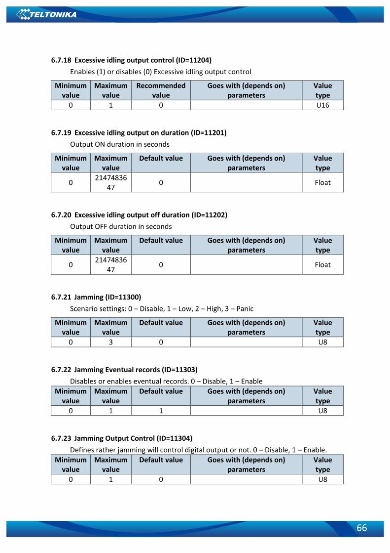
66
6.7.18 Excessive idling output control (ID=11204)
Enables (1) or disables (0) Excessive idling output control
Minimum value
Maximum value
Recommended value
Goes with (depends on) parameters
Value type
0 1 0 U16
6.7.19 Excessive idling output on duration (ID=11201)
Output ON duration in seconds
Minimum value
Maximum value
Default value Goes with (depends on) parameters
Value type
0 21474836
47 0 Float
6.7.20 Excessive idling output off duration (ID=11202)
Output OFF duration in seconds
Minimum value
Maximum value
Default value Goes with (depends on) parameters
Value type
0 21474836
47 0 Float
6.7.21 Jamming (ID=11300)
Scenario settings: 0 – Disable, 1 – Low, 2 – High, 3 – Panic
Minimum value
Maximum value
Default value Goes with (depends on) parameters
Value type
0 3 0 U8
6.7.22 Jamming Eventual records (ID=11303)
Disables or enables eventual records. 0 – Disable, 1 – Enable
Minimum value
Maximum value
Default value Goes with (depends on) parameters
Value type
0 1 1 U8
6.7.23 Jamming Output Control (ID=11304)
Defines rather jamming will control digital output or not. 0 – Disable, 1 – Enable.
Minimum value
Maximum value
Default value Goes with (depends on) parameters
Value type
0 1 0 U8

67
6.7.24 Jamming DOUT on duration [ms] (ID=11301)
Sets time period, that Dout will be on.
Minimum value
Maximum value
Default value Goes with (depends on) parameters
Value type
0 21474836
47 200 U8
6.7.25 Jamming DOUT off duration [ms] (ID=11302)
Sets time period, that Dout will be off.
Minimum value
Maximum value
Default value Goes with (depends on) parameters
Value type
0 21474836
47 200 U8
6.7.26 DOUT control via call (ID=12000)
Disables or enables dout control via call. 0 – Disable, 1 – Enable.
Minimum value
Maximum value
Default value Goes with (depends on) parameters
Value type
0 1 0 U8
6.7.27 DOUT deactivation settings (ID=12001)
Enables or disables dout deactivation by Din1. 0 – Disable, 1 – Enable.
Minimum value
Maximum value
Default value Goes with (depends on) parameters
Value type
0 1 0 U8
6.7.28 DOUT duration timeout [s] (ID=12002)
Defines the time that dout will be activated for.
Minimum value
Maximum value
Default value Goes with (depends on) parameters
Value type
0 21474836
47 5 U8
6.7.29 Trip priority priority (ID=11800)
Defines priority of trip scenario:
0 – disabled, 1 – low, 2 – high, 3 – panic
Minimum value
Maximum value
Default value Goes with (depends on) parameters
Value type
0 3 0 U8
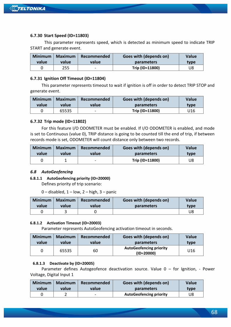
68
6.7.30 Start Speed (ID=11803)
This parameter represents speed, which is detected as minimum speed to indicate TRIP START and generate event.
Minimum value
Maximum value
Recommended value
Goes with (depends on) parameters
Value type
0 255 - Trip (ID=11800) U8
6.7.31 Ignition Off Timeout (ID=11804)
This parameter represents timeout to wait if ignition is off in order to detect TRIP STOP and generate event.
Minimum value
Maximum value
Recommended value
Goes with (depends on) parameters
Value type
0 65535 - Trip (ID=11800) U16
6.7.32 Trip mode (ID=11802)
For this feature I/O ODOMETER must be enabled. If I/O ODOMETER is enabled, and mode is set to Continuous (value 0), TRIP distance is going to be counted till the end of trip, if between records mode is set, ODOMETER will count distance only between two records.
Minimum value
Maximum value
Recommended value
Goes with (depends on) parameters
Value type
0 1 - Trip (ID=11800) U8
6.8 AutoGeofencing
6.8.1.1 AutoGeofencing priority (ID=20000)
Defines priority of trip scenario:
0 – disabled, 1 – low, 2 – high, 3 – panic
Minimum value
Maximum value
Recommended value
Goes with (depends on) parameters
Value type
0 3 0 U8
6.8.1.2 Activation Timeout (ID=20003)
Parameter represents AutoGeofencing activation timeout in seconds.
Minimum value
Maximum value
Recommended value
Goes with (depends on) parameters
Value type
0 65535 60 AutoGeofencing priority
(ID=20000) U16
6.8.1.3 Deactivate by (ID=20005)
Parameter defines Autogeofence deactivation source. Value 0 – for Ignition, - Power Voltage, Digital Input 1
Minimum value
Maximum value
Recommended value
Goes with (depends on) parameters
Value type
0 2 - AutoGeofencing priority U8
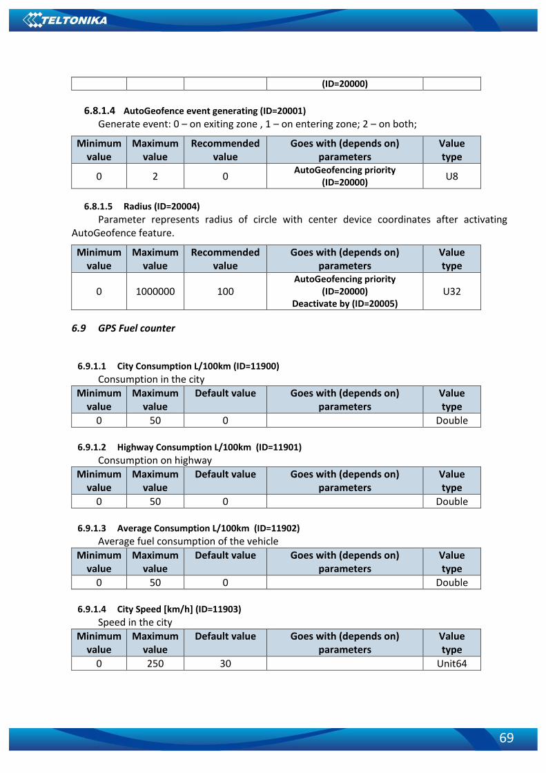
69
(ID=20000)
6.8.1.4 AutoGeofence event generating (ID=20001) Generate event: 0 – on exiting zone , 1 – on entering zone; 2 – on both;
Minimum value
Maximum value
Recommended value
Goes with (depends on) parameters
Value type
0 2 0 AutoGeofencing priority
(ID=20000) U8
6.8.1.5 Radius (ID=20004)
Parameter represents radius of circle with center device coordinates after activating AutoGeofence feature.
Minimum value
Maximum value
Recommended value
Goes with (depends on) parameters
Value type
0 1000000 100 AutoGeofencing priority
(ID=20000) Deactivate by (ID=20005)
U32
6.9 GPS Fuel counter
6.9.1.1 City Consumption L/100km (ID=11900)
Consumption in the city
Minimum value
Maximum value
Default value Goes with (depends on) parameters
Value type
0 50 0 Double
6.9.1.2 Highway Consumption L/100km (ID=11901)
Consumption on highway
Minimum value
Maximum value
Default value Goes with (depends on) parameters
Value type
0 50 0 Double
6.9.1.3 Average Consumption L/100km (ID=11902)
Average fuel consumption of the vehicle
Minimum value
Maximum value
Default value Goes with (depends on) parameters
Value type
0 50 0 Double
6.9.1.4 City Speed [km/h] (ID=11903)
Speed in the city
Minimum value
Maximum value
Default value Goes with (depends on) parameters
Value type
0 250 30 Unit64

70
6.9.1.5 Highway Speed [km/h] (ID=11904)
Speed on highway
Minimum value
Maximum value
Default value Goes with (depends on) parameters
Value type
0 250 90 Unit64
6.9.1.6 Average Speed [km/h] (ID=11905)
Average speed of the vehicle
Minimum value
Maximum value
Default value Goes with (depends on) parameters
Value type
0 250 60 Unit64
6.9.1.7 Correction coefficient (ID=11906)
Sets the correction coefficient
Minimum value
Maximum value
Default value Goes with (depends on) parameters
Value type
0.01 2 1 Double
6.9.1.8 Fuel Consumption on Idling [L/h] (ID=11907)
Sets fuel consumption while vehicle is idling
Minimum value
Maximum value
Default value Goes with (depends on) parameters
Value type
0 5 1 Double
6.9.1.9 Higher Speeds Add [%] (ID=11908)
Minimum value
Maximum value
Default value Goes with (depends on) parameters
Value type
0 250 20 Unit64
6.9.1.10 Highway Consumption every km/h (ID=11909)
Minimum value
Maximum value
Default value Goes with (depends on) parameters
Value type
0 100 50 Unit64
6.10 Scenarios Accelerometer
6.10.1 Unplug Detection
6.10.1.1 Scenario settings (ID=11500) Sets priority of the scenario: 0 – Disable, 1 – Low Priority, 2 – High Priority, 3 – Panic
Priority
Minimum value
Maximum value
default value Goes with (depends on) parameters
Value type
0 3 0 U64
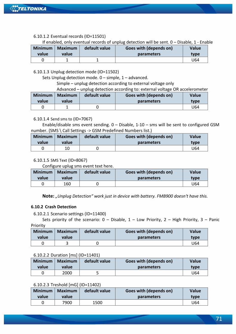
71
6.10.1.2 Eventual records (ID=11501) If enabled, only eventual records of unplug detection will be sent. 0 – Disable, 1 - Enable
Minimum value
Maximum value
default value Goes with (depends on) parameters
Value type
0 1 1 U64
6.10.1.3 Unplug detection mode (ID=11502)
Sets Unplug detection mode. 0 – simple, 1 – advanced. Simple – unplug detection according to external voltage only Advanced – unplug detection according to: external voltage OR accelerometer
Minimum value
Maximum value
default value Goes with (depends on) parameters
Value type
0 1 0 U64
6.10.1.4 Send sms to (ID=7067)
Enable/disable sms event sending. 0 – Disable, 1-10 – sms will be sent to configured GSM number. (SMS \ Call Settings -> GSM Predefined Numbers list.)
Minimum value
Maximum value
default value Goes with (depends on) parameters
Value type
0 10 0 U64
6.10.1.5 SMS Text (ID=8067)
Configure uplug sms event text here.
Minimum value
Maximum value
default value Goes with (depends on) parameters
Value type
0 160 0 U64
Note: „Unplug Detection“ work just in device with battery. FMB900 doesn‘t have this.
6.10.2 Crash Detection
6.10.2.1 Scenario settings (ID=11400) Sets priority of the scenario: 0 – Disable, 1 – Low Priority, 2 – High Priority, 3 – Panic
Priority
Minimum value
Maximum value
default value Goes with (depends on) parameters
Value type
0 3 0 U64
6.10.2.2 Duration [ms] (ID=11401)
Minimum value
Maximum value
default value Goes with (depends on) parameters
Value type
0 2000 5 U64
6.10.2.3 Treshold [mG] (ID=11402)
Minimum value
Maximum value
default value Goes with (depends on) parameters
Value type
0 7900 1500 U64

72
6.10.2.4 Crash trace (ID=11406)
Minimum value
Maximum value
default value Goes with (depends on) parameters
Value type
0 1 0 U64
6.11 Bluetooth
6.11.1.1 BT Radio (ID=800) Enables or disable Bluetooth feature. 0 – Disabled, 1 – Enable hidden, 2 – Enable visible
Minimum value
Maximum value
default value Goes with (depends on) parameters
Value type
0 2 0 U64
6.11.1.2 Local name (ID 801)
Parameter defines a visible name of FMBX device.
Minimum value
Maximum value
default value Goes with (depends on) parameters
Value type
0 Symbols
30 Symbols
- String
6.11.1.3 Local PIN (ID=802)
Parameter Lets to configure Bluetooth PIN.
Minimum value
Maximum value
default value Goes with (depends on) parameters
Value type
0 Symbols
4 Symbols 5555 String
6.11.1.4 Security mode (ID=803)
Parameter defines a security mode of FMBX device. 0 – PIN only, 1 – PIN and MAC, 2 – MAC only, 3 – None.
Minimum value
Maximum value
default value Goes with (depends on) parameters
Value type
0 3 0 U64
6.11.1.5 External MAC (ID=804) Defines external device’s MAC, for FMB920 to auto connect to.
Minimum value
Maximum value
default value Goes with (depends on) parameters
Value type
0 symbols 12
symbols 0 string
6.11.1.6 External name (ID=805)
Defines external device’s name, for FMB920 to auto connect to.
Minimum value
Maximum value
default value Goes with (depends on) parameters
Value type

73
0 symbols 30
symbols 0 string
6.11.1.7 External PIN (ID=806)
Defines external device’s PIN, for FMB920 to auto connect to.
Minimum value
Maximum value
default value Goes with (depends on) parameters
Value type
0 symbols 8 symbols 0 string
6.11.1.8 Connection mode (ID=807)
Defines a mode in which FMB920 will connect to external devices. 0 – None, 1 – FMB920 will connect to Hands Free Headset, 2 – FMB920 will connect to OBDII
Bluetooth dongle.
Minimum value
Maximum value
default value Goes with (depends on) parameters
Value type
0 2 0 U64
6.11.1.9 Authorized devices MAC list (ID=830 - 834)
Parameter allows to add an authorized devices MAC for connection to FMB920
Minimum value
Maximum value
default value Goes with (depends on) parameters
Value type
0 symbols 12 symbols - String
6.12 I/O parameters
I/O properties are additional data sources which are recorded along with usual GPS data.
6.12.1 I/O#1 property parameter Ignition (ID=50000)
Parameter defines I/O property value. Possible values: 0-Disabled; 1-Low; 2-High; 3-Panic.
Minimum value
Maximum value
Recommended value
Goes with (depends on) parameters
Value type
0 3 -
I/O#1 priority (ID=50000) I/O#1 logic operand (ID=50001)
I/O#1 High level (ID=50002) I/O#1 Low level (ID=50003)
I/O#1 Event only (ID=50004) I/O#1 averaging length (ID=50005)
S8
6.12.2 I/O#1 Logic operand (ID=50001)
Parameter defines eventual record is saved. Possible values: 0 – On Exit; 1-On Entrance; 2-Both; 3-Monitoring; 4-Hysteris; 5-On Change; 6-On Delta Change
Minimum value
Maximum value
Recommended value
Goes with (depends on) parameters
Value type
0 6 0 I/O#1 priority (ID=50000)
I/O#1 logic operand (ID=50001) S8

74
I/O#1 High level (ID=50002) I/O#1 Low level (ID=50003)
I/O#1 Event only (ID=50004) I/O#1 averaging length (ID=50005)
6.12.3 I/O#1 High level (ID=50002)
Parameter defines high value of triggered I/O property. This parameter is used to set thresholds for I/O properties to generate events.
Minimum value
Maximum value
Recommended value
Goes with (depends on) parameters Value type
-2147483647 2147483647 1
I/O#1 priority (ID=50000) I/O#1 logic operand (ID=50001)
I/O#1 High level (ID=50002) I/O#1 Low level (ID=50003)
I/O#1 Event only (ID=50004) I/O#1 averaging length (ID=50005)
S32
6.12.4 I/O#1 Low level (ID=50003)
Parameter defines low value of triggered I/O property. This parameter is used to set thresholds for I/O properties to generate events.
Minimum value
Maximum value
Recommended value
Goes with (depends on) parameters Value type
-2147483647 2147483647 0
I/O#1 priority (ID=50000) I/O#1 logic operand (ID=50001)
I/O#1 High level (ID=50002) I/O#1 Low level (ID=50003)
I/O#1 Event only (ID=50004) I/O#1 averaging length (ID=50005)
S32
6.12.5 I/O#1 Event only (ID=50004)
Parameter defines whether element should be sent only when event is generated. Possible values:
1 – Yes (parameter ID and value is sent when event is generated);
0 – No (parameter ID and value is sent in every record).
Minimal value
Maximum value
Recommended value
Goes with (depends on) parameters
Value type
0 1 0
I/O#1 priority (ID=50000) I/O#1 logic operand (ID=50001)
I/O#1 High level (ID=50002) I/O#1 Low level (ID=50003)
I/O#1 Event only (ID=50004) I/O#1 averaging length (ID=50005)
S8

75
6.12.6 I/O#1 averaging length (ID=50005)
Parameter defines I/O property sample length to average. If no averaging needed default value is 1.
Minimum value
Maximum value
Recommended value
Goes with (depends on) parameters Value type
0 2147483647 1
I/O#1 priority (ID=50000) I/O#1 logic operand (ID=50001)
I/O#1 High level (ID=50002) I/O#1 Low level (ID=50003)
I/O#1 Event only (ID=50004) I/O#1 averaging length (ID=50005)
S32
Other I/O property elements can be configured in same logic. All I/O element parameters
are listed in the next table.
6.13 I\O elements parameters and types.
Parameter ID
Parameter Type
Default value Value range
Parameter name Min Max
50000 Uint8 1 0 3 Ignition Priority
50001 Uint8 5 0 6 Ignition Operand
50002 Uint8 0 0 1 Ignition High level
50003 Uint8 0 0 1 Ignition Low level
50004 Uint8 0 0 1 Ignition Event only
50005 Uint16 10 0 65535 Ignition Average
7000 Uint8 0 0 10 Send SMS
8000 String 0 0 160 SMS Text
50010 Uint8 1 0 3 Movement Priority
50011 Uint8 5 0 6 Movement Operand
50012 Uint8 0 0 1 Movement High level
50013 Uint8 0 0 1 Movement Low level
50014 Uint8 0 0 1 Movement Event only
50015 Uint16 1 0 65535 Movement Average
7001 Uint8 0 0 10 Send SMS
8001 String 0 0 160 SMS Text
50020 Uint8 1 0 3 Data Mode Priority
50021 Uint8 5 0 6 Data Mode Operand
50022 Uint8 0 0 5 Data Mode Hight level
50023 Uint8 0 0 5 Data Mode Low level
50024 Uint8 0 0 1 Data Mode Event only
7002 Uint8 0 0 10 Send SMS
8002 String 0 0 160 SMS Text
50030 Uint8 1 0 3 GSM Signal Priority
50031 Uint8 5 0 6 GSM Signal Operand
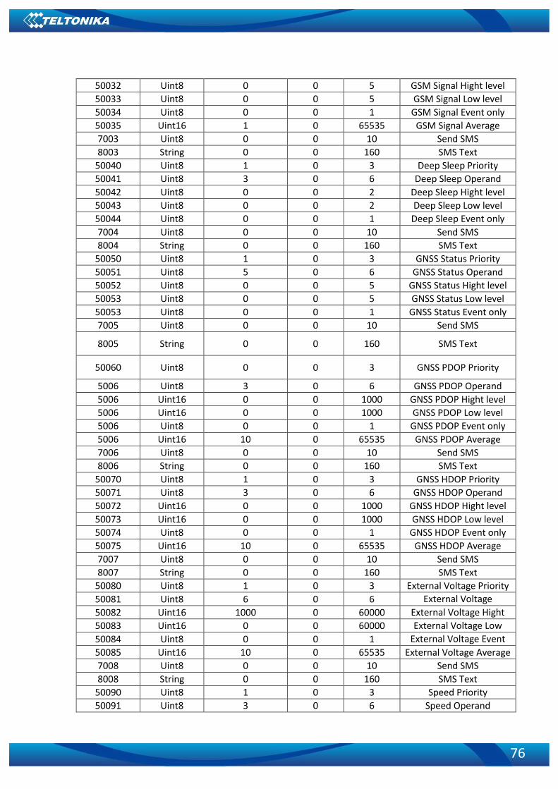
76
50032 Uint8 0 0 5 GSM Signal Hight level
50033 Uint8 0 0 5 GSM Signal Low level
50034 Uint8 0 0 1 GSM Signal Event only
50035 Uint16 1 0 65535 GSM Signal Average
7003 Uint8 0 0 10 Send SMS
8003 String 0 0 160 SMS Text
50040 Uint8 1 0 3 Deep Sleep Priority
50041 Uint8 3 0 6 Deep Sleep Operand
50042 Uint8 0 0 2 Deep Sleep Hight level
50043 Uint8 0 0 2 Deep Sleep Low level
50044 Uint8 0 0 1 Deep Sleep Event only
7004 Uint8 0 0 10 Send SMS
8004 String 0 0 160 SMS Text
50050 Uint8 1 0 3 GNSS Status Priority
50051 Uint8 5 0 6 GNSS Status Operand
50052 Uint8 0 0 5 GNSS Status Hight level
50053 Uint8 0 0 5 GNSS Status Low level
50053 Uint8 0 0 1 GNSS Status Event only
7005 Uint8 0 0 10 Send SMS
8005 String 0 0 160 SMS Text
50060 Uint8 0 0 3 GNSS PDOP Priority
5006 Uint8 3 0 6 GNSS PDOP Operand
5006 Uint16 0 0 1000 GNSS PDOP Hight level
5006 Uint16 0 0 1000 GNSS PDOP Low level
5006 Uint8 0 0 1 GNSS PDOP Event only
5006 Uint16 10 0 65535 GNSS PDOP Average
7006 Uint8 0 0 10 Send SMS
8006 String 0 0 160 SMS Text
50070 Uint8 1 0 3 GNSS HDOP Priority
50071 Uint8 3 0 6 GNSS HDOP Operand
50072 Uint16 0 0 1000 GNSS HDOP Hight level
50073 Uint16 0 0 1000 GNSS HDOP Low level
50074 Uint8 0 0 1 GNSS HDOP Event only
50075 Uint16 10 0 65535 GNSS HDOP Average
7007 Uint8 0 0 10 Send SMS
8007 String 0 0 160 SMS Text
50080 Uint8 1 0 3 External Voltage Priority
50081 Uint8 6 0 6 External Voltage Operand 50082 Uint16 1000 0 60000 External Voltage Hight
level 50083 Uint16 0 0 60000 External Voltage Low level 50084 Uint8 0 0 1 External Voltage Event only 50085 Uint16 10 0 65535 External Voltage Average
7008 Uint8 0 0 10 Send SMS
8008 String 0 0 160 SMS Text
50090 Uint8 1 0 3 Speed Priority
50091 Uint8 3 0 6 Speed Operand
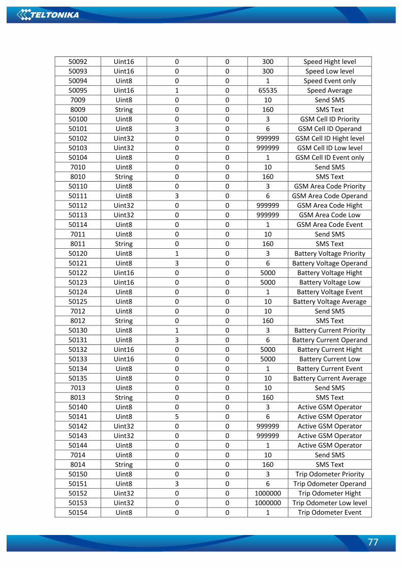
77
50092 Uint16 0 0 300 Speed Hight level
50093 Uint16 0 0 300 Speed Low level
50094 Uint8 0 0 1 Speed Event only
50095 Uint16 1 0 65535 Speed Average
7009 Uint8 0 0 10 Send SMS
8009 String 0 0 160 SMS Text
50100 Uint8 0 0 3 GSM Cell ID Priority
50101 Uint8 3 0 6 GSM Cell ID Operand
50102 Uint32 0 0 999999 GSM Cell ID Hight level
50103 Uint32 0 0 999999 GSM Cell ID Low level
50104 Uint8 0 0 1 GSM Cell ID Event only
7010 Uint8 0 0 10 Send SMS
8010 String 0 0 160 SMS Text
50110 Uint8 0 0 3 GSM Area Code Priority
50111 Uint8 3 0 6 GSM Area Code Operand
50112 Uint32 0 0 999999 GSM Area Code Hight level 50113 Uint32 0 0 999999 GSM Area Code Low level 50114 Uint8 0 0 1 GSM Area Code Event only 7011 Uint8 0 0 10 Send SMS
8011 String 0 0 160 SMS Text
50120 Uint8 1 0 3 Battery Voltage Priority
50121 Uint8 3 0 6 Battery Voltage Operand
50122 Uint16 0 0 5000 Battery Voltage Hight level 50123 Uint16 0 0 5000 Battery Voltage Low level 50124 Uint8 0 0 1 Battery Voltage Event only 50125 Uint8 0 0 10 Battery Voltage Average
7012 Uint8 0 0 10 Send SMS
8012 String 0 0 160 SMS Text
50130 Uint8 1 0 3 Battery Current Priority
50131 Uint8 3 0 6 Battery Current Operand
50132 Uint16 0 0 5000 Battery Current Hight level 50133 Uint16 0 0 5000 Battery Current Low level 50134 Uint8 0 0 1 Battery Current Event only 50135 Uint8 0 0 10 Battery Current Average
7013 Uint8 0 0 10 Send SMS
8013 String 0 0 160 SMS Text
50140 Uint8 0 0 3 Active GSM Operator Priority 50141 Uint8 5 0 6 Active GSM Operator
Operand 50142 Uint32 0 0 999999 Active GSM Operator Hight level 50143 Uint32 0 0 999999 Active GSM Operator Low level 50144 Uint8 0 0 1 Active GSM Operator
Event only 7014 Uint8 0 0 10 Send SMS
8014 String 0 0 160 SMS Text
50150 Uint8 0 0 3 Trip Odometer Priority
50151 Uint8 3 0 6 Trip Odometer Operand
50152 Uint32 0 0 1000000 Trip Odometer Hight level 50153 Uint32 0 0 1000000 Trip Odometer Low level
50154 Uint8 0 0 1 Trip Odometer Event only

78
7015 Uint8 0 0 10 Send SMS
8015 String 0 0 160 SMS Text
50160 Uint8 0 0 3 Total Odometer Priority
50161 Uint8 3 0 6 Total Odometer Operand 50162 Uint32 0 0 10000000 Total Odometer Hight
level 50163 Uint32 0 0 10000000 Total Odometer Low level 50164 Uint8 0 0 1 Total Odometer Event only 7016 Uint8 0 0 10 Send SMS
8016 String 0 0 160 SMS Text
50170 Uint8 0 0 3 Digital Input 1 Priority
50171 Uint8 0 0 6 Digital Input 1 Operand
50172 Uint8 0 0 1 Digital Input 1 Hight level 50173 Uint8 0 0 1 Digital Input 1 Low level
50174 Uint8 0 0 1 Digital Input 1 Event only
50175 Uint16 1 0 65535 Digital Input 1 Average
7017 Uint8 0 0 10 Send SMS
8017 String 0 0 160 SMS Text
50180 Uint8 0 0 3 Analog Input 1 Priority
50181 Uint8 6 0 6 Analog Input 1 Operand
50182 Uint16 1000 0 30000 Analog Input 1 Hight level 50183 Uint16 0 0 30000 Analog Input 1 Low level
50184 Uint8 0 0 1 Analog Input 1 Event only 50185 Uint16 10 0 65535 Analog Input 1 Average
7018 Uint8 0 0 10 Send SMS
8018 String 0 0 160 SMS Text
50190 Uint8 0 0 3 Digital Output 1 Priority
50191 Uint8 0 0 6 Digital Output 1 Operand 50192 Uint8 0 0 1 Digital Output 1 Hight
level 50193 Uint8 0 0 1 Digital Output 1 Low level 50194 Uint8 0 0 1 Digital Output 1 Event only 50195 Uint16 1 0 65535 Digital Output 1 Average
7019 Uint8 0 0 10 Send SMS
8019 String 0 0 160 SMS Text
50200 Uint8 0 0 3 Fuel Used GPS Priority
50201 Uint8 3 0 6 Fuel Used GPS Operand
50202 Uint32 0 0 1000000 Fuel Used GPS Hight level 50203 Uint32 0 0 1000000 Fuel Used GPS Low level
50204 Uint8 0 0 1 Fuel Used GPS Event only 50205 Uint16 1 0 65535 Fuel Used GPS Average
7020 Uint8 0 0 10 Send SMS
8020 String 0 0 160 SMS Text
50210 Uint8 0 0 3 Fuel Rate GPS Priority
50211 Uint8 3 0 6 Fuel Rate GPS Operand
50212 Uint32 0 0 1000000 Fuel Rate GPS Hight level
50213 Uint32 0 0 1000000 Fuel Rate GPS Low level
50214 Uint8 0 0 1 Fuel Rate GPS Event only
50215 Uint16 1 0 65535 Fuel Rate GPS Average

79
7021 Uint8 0 0 10 Send SMS
8021 String 0 0 160 SMS Text
50220 Uint8 0 0 3 Axis X Priority
50221 Uint8 3 0 6 Axis X Operand
50222 Uint16 0 -8000 8000 Axis X Hight level
50223 Uint16 0 -8000 8000 Axis X Low level
50224 Uint8 0 0 1 Axis X Event only
50225 Uint16 1 0 65535 Axis X Average
7022 Uint8 0 0 10 Send SMS
8022 String 0 0 160 SMS Text
50230 Uint8 0 0 3 Axis Y Priority
50231 Uint8 3 0 6 Axis Y Operand
50232 Uint16 0 -8000 8000 Axis Y Hight level
50233 Uint16 0 -8000 8000 Axis Y Low level
50234 Uint8 0 0 1 Axis Y Event only
50235 Uint16 1 0 65535 Axis Y Average
7023 Uint8 0 0 10 Send SMS
8023 String 0 0 160 SMS Text
50240 Uint8 0 0 3 Axis Z Priority
50241 Uint8 3 0 6 Axis Z Operand
50242 Uint16 0 -8000 8000 Axis Z Hight level
50243 Uint16 0 -8000 8000 Axis Z Low level
50244 Uint8 0 0 1 Axis Z Event only
50245 Uint16 1 0 65535 Axis Z Average
7024 Uint8 0 0 10 Send SMS
8024 String 0 0 160 SMS Text

80
7 Spy call functionality
To activate Spy call function user has to configure incoming call settings to Answer (Spy Call) and then spy call to FMB001 device can be made. The device will answer automatically and transmit sound to the user.
OBD Element Number OBD element parameters
I/O#1 – Number Of DTC 50250 – 50255
I/O#2 – Engine Load 50260 – 50265
I/O#3 – Coolant Temperature 50270 – 50275
I/O#4 – Short Fuel Trim 50280 – 50285
I/O#5 – Fuel Pressure 50290 – 50295
I/O#6 - Intake MAP 50300 – 50305
I/O#7 – Engine RPM 50310 – 50315
I/O#8 – Vehicle speed 50320 – 50325
I/O#9 – Timing advance 50330 – 50335
I/O#10 – Intake air temp. 50340 – 50345
I/O#11 – MAF 50350 – 50355
I/O#12 – Throttle position 50360 – 50365
I/O#13 – Run time since engine start 50370 – 50375
I/O#14 – Distance traveled MIL on 50380 – 50385
I/O#15 – Relative fuel rail pressure 50390 – 50395
I/O#16 – Commanded EGR 50400 – 50405
I/O#17 – EGR error 50410 – 50415
I/O#18 – Fuel level 50420 – 50425
I/O#19 – Dist. traveled since codes clear
50430 – 50435
I/O#20 – Barometric pressure 50440 – 50445
I/O#21 – Control module voltage 50450 – 50455
I/O#22 – Absolute load value 50460 – 50465
I/O#23 – Ambient air temp. 50470 – 50475
I/O#24 – Time run with MIL on 50480 – 50485
I/O#26 – T. since trouble codes clrd. 50490 – 50495
I/O#27 – Absolute fuel rail pressure 50500 – 50505
I/O#28 – Hybrid batt. pack rem. life 50510 – 50515
I/O#29 – Engine oil temperature 50520 – 50525
I/O#30 – fuel injection timing 50530 – 50535
I/O#31 – Fuel rate 50540 - 50545

81
Figure 22 Configured Spy Call
CHANGE LOG
Nr. Date Version Comments
1 2017-01-11 0.01 Preliminary draft release.
2 2017-01-24 0.02 Bluetooth radio, accelerometer scenarios, time synchronization explanation added, parameter IDs for remote configuration added.
3 2017-02-07 0.03 I/O element parameter IDs updated.
4 2017-02-21 0.04 Updated IO element “Event only” parameter values
5 2017-04-05 0.05 Updated I\O elements, sms ID parameter description.
6 2017-04-13 0.06 Added “Supported OBD protocols”.