Fluid Typing In Thinly Bedded Reservoirs th Offshore ... Typing In Thinly Bedded Reservoirs 10th...
31
Fluid Typing In Thinly Bedded Reservoirs 10 th Offshore Mediterranean Conference – OMC Ravenna, Italy, March 2011 Rl d Ch li Roland Chemali Chief Petrophysicist Sperry Drilling Maged Fam Halliburton Technology Manager
Transcript of Fluid Typing In Thinly Bedded Reservoirs th Offshore ... Typing In Thinly Bedded Reservoirs 10th...
Fluid Typing In Thinly Bedded Reservoirs
10th Offshore Mediterranean Conference – OMCRavenna, Italy, March 2011
R l d Ch liRoland ChemaliChief Petrophysicist Sperry Drilling
Maged FamHalliburton Technology Manager

Laminated Formations
RvRhRh
© 2009 Halliburton. All Rights Reserved. 2

Laminated ReservoirsLayers with different petrophysical properties such as interbedded sandstoneLayers with different petrophysical properties such as interbedded sandstoneand shale with thicknesses below the vertical resolution of the logging toolmeasurement
© 2009 Halliburton. All Rights Reserved. 3

Methods for Reservoir Fluid Typing
M d L i / G Ch h- Mud Logging / Gas Chromatography
- Logs (WL & LWD)
- Pressure Gradient
Rock Sample- Rock Sample
- Fluid Sample
Gas-Liquid Contact Depth
© 2009 Halliburton. All Rights Reserved. 4
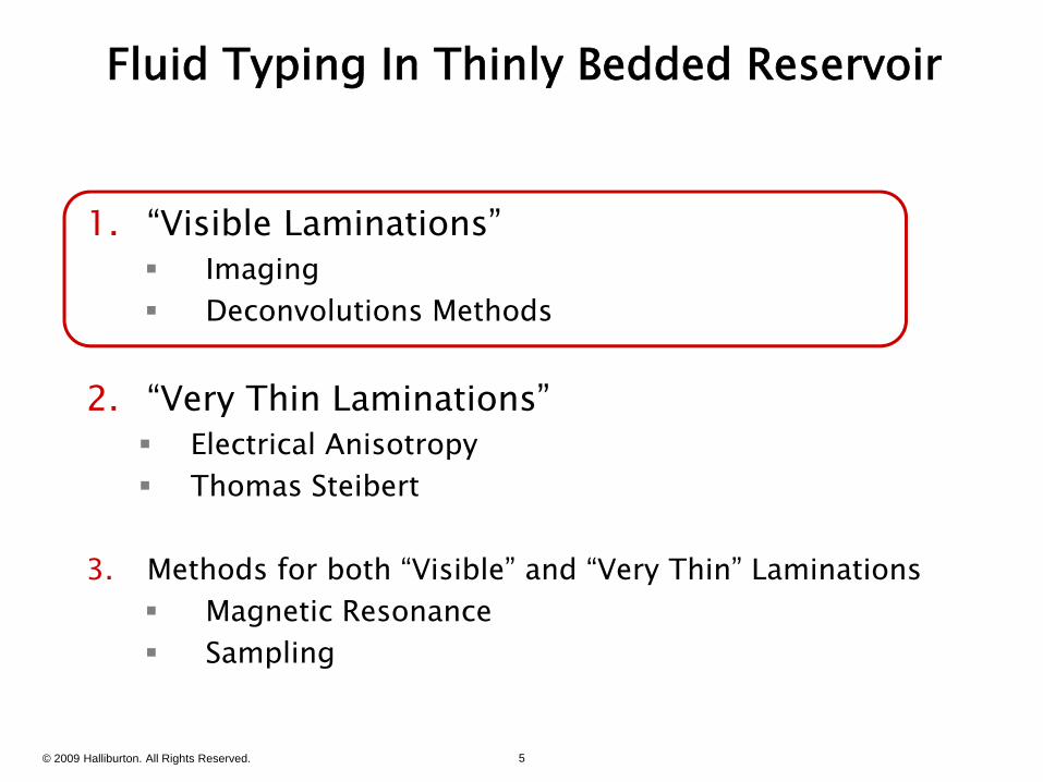
Fluid Typing In Thinly Bedded Reservoir
1 “Visible Laminations”1. Visible Laminations Imaging Deconvolutions Methods
2. “Very Thin Laminations” Electrical Anisotropy Electrical Anisotropy Thomas Steibert
3 h d f b h “ bl ” d “ h ”3. Methods for both “Visible” and “Very Thin” Laminations Magnetic Resonance Sampling
© 2009 Halliburton. All Rights Reserved. 5

Standard vs. High Resolution Tool Response in Laminated Shaly Sand Reservoirs
© 2009 Halliburton. All Rights Reserved. 6
SPE 30608

Standard vs. High Resolution Interpretation in Laminated Shaly Sand Reservoirs
3’ Net Pay3’ Net Pay9’ Net Pay9’ Net Pay
© 2009 Halliburton. All Rights Reserved. 7
Standard ResolutionHigh ResolutionSPE 30608

Fluid Typing In Thinly Bedded Reservoir
1 “Visible Laminations”1. Visible Laminations Imaging Deconvolutions Methods
2. “Very Thin Laminations” Electrical Anisotropy Electrical Anisotropy Thomas Steibert
3 h d f b h “ bl ” d “ h ”3. Methods for both “Visible” and “Very Thin” Laminations Magnetic Resonance Sampling
© 2009 Halliburton. All Rights Reserved. 8

Anisotropy in Turbidites and LaminationsRv = “Vertical” ResistivityRh = “Horizontal” Resistivity Anisotropy Ratio = Rv/Rh
RvRRh
© 2009 Halliburton. All Rights Reserved. 9

Anisotropy in Sand Shale SequencesThe Difference Between Micro-Anisotropy and Macro-Anisotropy
is Subjective and Depends On Measuring Instrument
Rsand= 20 Ohm-mRh ≈ 2 Ohm-m
Rshale=1 Ohm-m
Rh ≈ 2 Ohm-m
Rv ≈ 10 Ohm m
Rh ≈ 2 Ohm-m
Rv ≈ 10 Ohm-m Rv ≈ 10 Ohm-m
Anisotropy Ratio = ? On right hand side
© 2009 Halliburton. All Rights Reserved. 10
py gAnisotropy Ratio = ? On left hand side

Anisotropy in Sand Shale SequencesThe Difference Between Micro-Anisotropy and Macro-Anisotropyis Subjective and Depends On Measuring Instrument
Rsand= 20 Ohm-mRh ≈ 2 Ohm-m
Rshale=1 Ohm-m
Rh ≈ 2 Ohm-m
Rv ≈ 10 Ohm m
Rh ≈ 2 Ohm-m
Rv ≈ 10 Ohm-m Rv ≈ 10 Ohm-m
Th V i l C il A
© 2009 Halliburton. All Rights Reserved. 11
The Vertical Coil ArrayMeasures Only Rh i.e. 2 Ohm-m i.e. “”Wet”

Anisotropy: Historic PerspectiveAnisotropy in the 70’sAnisotropy in the 70 s
Paper/Patent for Oil Base Dipmeter
© 2009 Halliburton. All Rights Reserved. 12

Anisotropy: Historic Perspective
Anisotropy in the 80’sExplains Separation Between Induction and Laterolog
A Nuisance to Contend WithA Nuisance to Contend With
© 2009 Halliburton. All Rights Reserved. 13
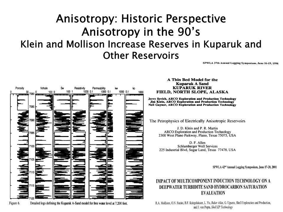
Anisotropy: Historic PerspectiveAnisotropy in the 90’sAnisotropy in the 90 s
Klein and Mollison Increase Reserves in Kuparuk and Other Reservoirs
© 2009 Halliburton. All Rights Reserved. 14

From Anisotropy to Saturation in Laminated Reservoirs1. Measure Rv and Rh
2 I t R h l2. Input Rshale3. Get Rsand and Vshale
RvRh
Rsand
© 2009 Halliburton. All Rights Reserved. 15
Rshale Vshale

Azimuthal Deep ResistivityUncompensated Upper Transmitter Measurement
TL-16 TL-32 TL-48R1 R2 R3
TU-48 TU-32 TU-16
3 x Receivers
Uncompensated Upper Transmitter Measurement
Measuring Electrical Anisotropy with ADR
© 2009 Halliburton. All Rights Reserved. 16
g py

Azimuthal Deep ResistivityUncompensated Lower Transmitter Measurement
TU-48 TU-32 TU-16 TL-16 TL-32 TL-48R1 R2 R3
TU-48 TU-32 TU-16
Uncompensated Lower Transmitter Measurement
Measuring Electrical Anisotropy with ADR
© 2009 Halliburton. All Rights Reserved. 17
g py

Azimuthal Deep ResistivityCompensated Measurement
TU-48 TU-32 TU-16 TL-16 TL-32 TL-48R1 R2 R3
Uncompensated Upper Transmitter Measurement
Uncompensated Lower Transmitter Measurement+Uncompensated Lower Transmitter Measurement+Compensated Measurement
© 2009 Halliburton. All Rights Reserved. 18
Measuring Electrical Anisotropy with ADR

Anisotropic FormationRh = 1 Ohm-m Rv = 2 Ohm-m
Relative Dip = 0 deg
Relative Dip = 90 deg
Compensated Azimuthal ResistivityADR 16 in; 2 MHz Up Down and AverageO
hm-m
-ADR 16 in; 2 MHz, Up, Down and Average-ADR 48 in; 500 KHz, Up, Down and Average
O
Uncompensated Geosignal10
eg GeosignalUncompensated GeosignalUpper Transmitter
Compensated Geosignal
5
0
de Geosignal
© 2009 Halliburton. All Rights Reserved. 19
Uncompensated GeosignalLower Transmitter
- 5
10

Anisotropic FormationRh = 1 Ohm-m Rv = 3 Ohm-m
Relative Dip = 0 deg
Relative Dip = 90 deg
Compensated Azimuthal ResistivityADR 16 in; 2 MHz Up Down and AverageO
hm-m
-ADR 16 in; 2 MHz, Up, Down and Average-ADR 48 in; 500 KHz, Up, Down and Average
O
Uncompensated GeosignalU T itt
10
eg GeosignalUpper Transmitter
Compensated Geosignal
5
0
de Geosignal
© 2009 Halliburton. All Rights Reserved. 20
Uncompensated GeosignalLower Transmitter
- 5
10

Isotropic FormationRh = 1 Ohm-m Rv = 1 Ohm-m
Relative Dip = 0 deg
Relative Dip = 90 deg
Compensated Azimuthal ResistivityOhm
-m
Compensated Azimuthal Resistivity-ADR 16 in; 2 MHz, Up, Down and Average-ADR 48 in; 500 KHz, Up, Down and Average
O
10
eg GeosignalUncompensated Geosignal
Upper TransmitterUncompensated Geosignal
Lower TransmitterCompensated Geosignal
5
0
de Geosignal
© 2009 Halliburton. All Rights Reserved. 21
- 5
10

© 2009 Halliburton. All Rights Reserved. 22

Fluid Typing In Thinly Bedded Reservoir
1 “Visible Laminations”1. Visible Laminations Imaging Deconvolutions Methods
2. “Very Thin Laminations” Electrical Anisotropy Electrical Anisotropy Thomas Steibert
3 h d f b h “ bl ” d “ h ”3. Methods for both “Visible” and “Very Thin” Laminations Magnetic Resonance Sampling
© 2009 Halliburton. All Rights Reserved. 23

MRIL T1 & T2 Response to Fluids & Reservoir Conditions
M
Time, sec Pola
rizat
ion
T1
W t
e, sec
.2983TTT
BB 12
Water:
Oil: Poro
sity
.298
1.2TTT BB 12
Gas:1025TT
3 . Incr
emen
tal
T2
© 2009 Halliburton. All Rights Reserved. 24
T1025TT 1.17
BB 12
Time, msec

EMI & MRIL Data Integration
nSe
ctio
nna
ted
SLa
mi
© 2009 Halliburton. All Rights Reserved. 25 MRIL ResistivityTotal Image 60 mEnhanced Image
2.6 m
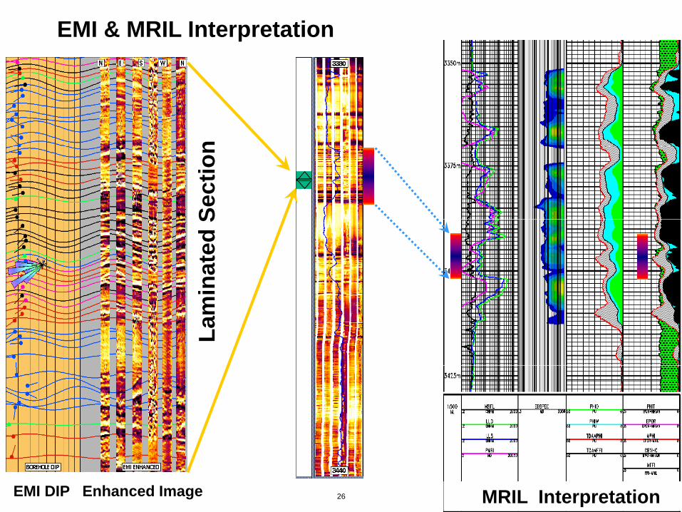
EMI & MRIL Interpretation
nSe
ctio
nin
ated
SLa
mi
© 2009 Halliburton. All Rights Reserved. 26 MRIL InterpretationEMI DIP Enhanced Image

Fluid Typing & Sampling in Laminated Reservoirs
RDTDual Probe 1”
RDTDual Probe 1”
RDTOval Pad 7.25”
RDTOval Pad 7.25”
7.25 ”
© 2009 Halliburton. All Rights Reserved. 27

© 2009 Halliburton. All Rights Reserved. 28
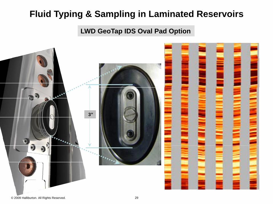
Fluid Typing & Sampling in Laminated Reservoirs
LWD G T IDS O l P d O tiLWD G T IDS O l P d O tiLWD GeoTap IDS Oval Pad OptionLWD GeoTap IDS Oval Pad Option
3”
© 2009 Halliburton. All Rights Reserved. 29

Fluid Typing & Sampling in Laminated Reservoirs
RDT - Dual Packer / Straddle Packer OptionRDT - Dual Packer / Straddle Packer OptionRDT Dual Packer / Straddle Packer OptionRDT Dual Packer / Straddle Packer Option
~ 40”
© 2009 Halliburton. All Rights Reserved. 30
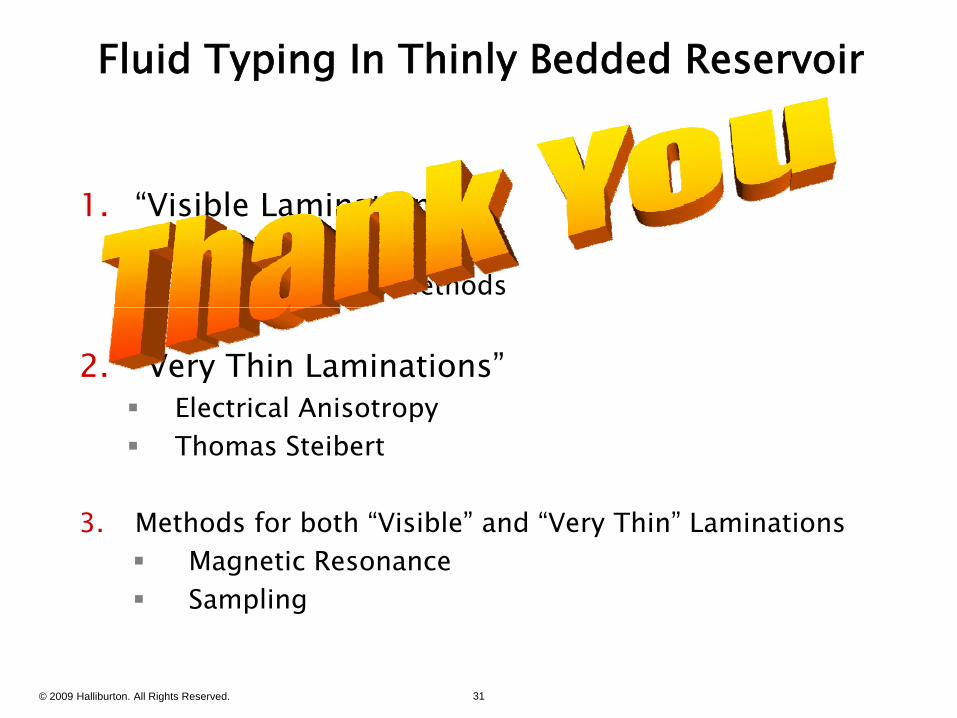
Fluid Typing In Thinly Bedded Reservoir
1 “Visible Laminations”1. Visible Laminations Imaging Deconvolutions Methods
2. “Very Thin Laminations” Electrical Anisotropy Electrical Anisotropy Thomas Steibert
3 h d f b h “ bl ” d “ h ”3. Methods for both “Visible” and “Very Thin” Laminations Magnetic Resonance Sampling
© 2009 Halliburton. All Rights Reserved. 31