Flowfield-smoothing technique in pulse detonation...
27
Flowfield-smoothing technique in pulse detonation engine T.Yatsufusa, K. Yoshinaga, T. Ofuka, A. Ochi T. Endo, and S. Taki (Hiroshima univ., Japan) S. Aoki, and Y. Umeda (Toho Gas Co., Ltd., Japan) 17th International Symposium on Airbreathing Engine Munich, 4.-9. September 2005 1 ISABE-2005- 1049
Transcript of Flowfield-smoothing technique in pulse detonation...

Flowfield-smoothing technique in pulse detonation engine
T.Yatsufusa, K. Yoshinaga, T. Ofuka, A. OchiT. Endo, and S. Taki (Hiroshima univ., Japan)
S. Aoki, and Y. Umeda (Toho Gas Co., Ltd., Japan)
17th International Symposium on Airbreathing EngineMunich, 4.-9. September 2005
1ISABE-2005- 1049
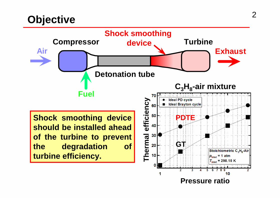
PDTE has inherently higher thermal efficiency than conventional gas turbines.
Intermittent exhaust of PDTE degrades the turbine efficiency.
Objective 2
Compressor
Detonation tube
TurbineAir
Fuel
Exhaust
C3H8-air mixture
Pressure ratio
Ther
mal
effi
cien
cyGT
PDTE
Shock smoothing device
Shock smoothing device should be installed ahead of the turbine to prevent the degradation of turbine efficiency.

Outline
• Objective• Outline• Details of experimental setup• Effects of diffuser tube• Effects of multi-step reflector• Conclusion• Work in progress
3

4
Shock Diffuser converts a strong shock wave into the series of weaker shock waves.
The effect of the shock diffusion is intrinsically transient.
Function of shock diffuser

5
A strong shock wave is divided into the several fragments, which propagate along the paths with different length. After then they merge together.
Principle of shock diffuser

Shock diffuser (prototype) 6
(Dimensions are in mm)
Series of weaker shock waves
Shock!

7
Outlet
P3
Confinement chamber
0 π/2 π
A shock wave is gradually exhausted from V-slit, and the series of weak shock waves continuously emitted from the outlet.
timePre
ssu
re
Diffuser tube
8
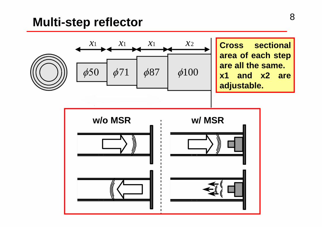
50φ 71φ 87φ 100φ
1x 1x 2x1x
Multi-step reflector
Cross sectional area of each step are all the same.x1 and x2 are adjustable.
w/o MSR w/ MSR

9
(Dimensions are in mm)
Detonation tube for shock diffuser experiments
The flame speed is measured by the ionization probes I1 and I2.
The pressure transducer P2 is located in the air-filled portion, where the inert shock wave propagates.
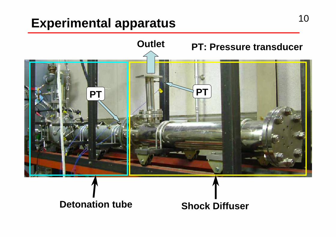
Detonation tube Shock Diffuser
Outlet
PTPT
PT: Pressure transducer
10Experimental apparatus

11
Mixture White gasoline-airEquivalence ratio 1.1Initial pressure 1atmC-J velocity 1820m/s
Measureddetonation speed 1670±100m/s
Experimental conditions
It is confirmed that the detonation was generated in all experiments.

12Effects ofconfinement chamberPressure histories at P2 and P3 in the case of confinement chamber only.
Detonation tube to shock diffuser
Shock diffuser to Detonation tube
Propagate direction

13Effects of the diffuser tubePressure histories at P3 in the case of no multi-step reflector.
P3
0
π/2
π
Shock waves from the detonation tube to the shock diffuser was strongly diffused by diffuser tube.

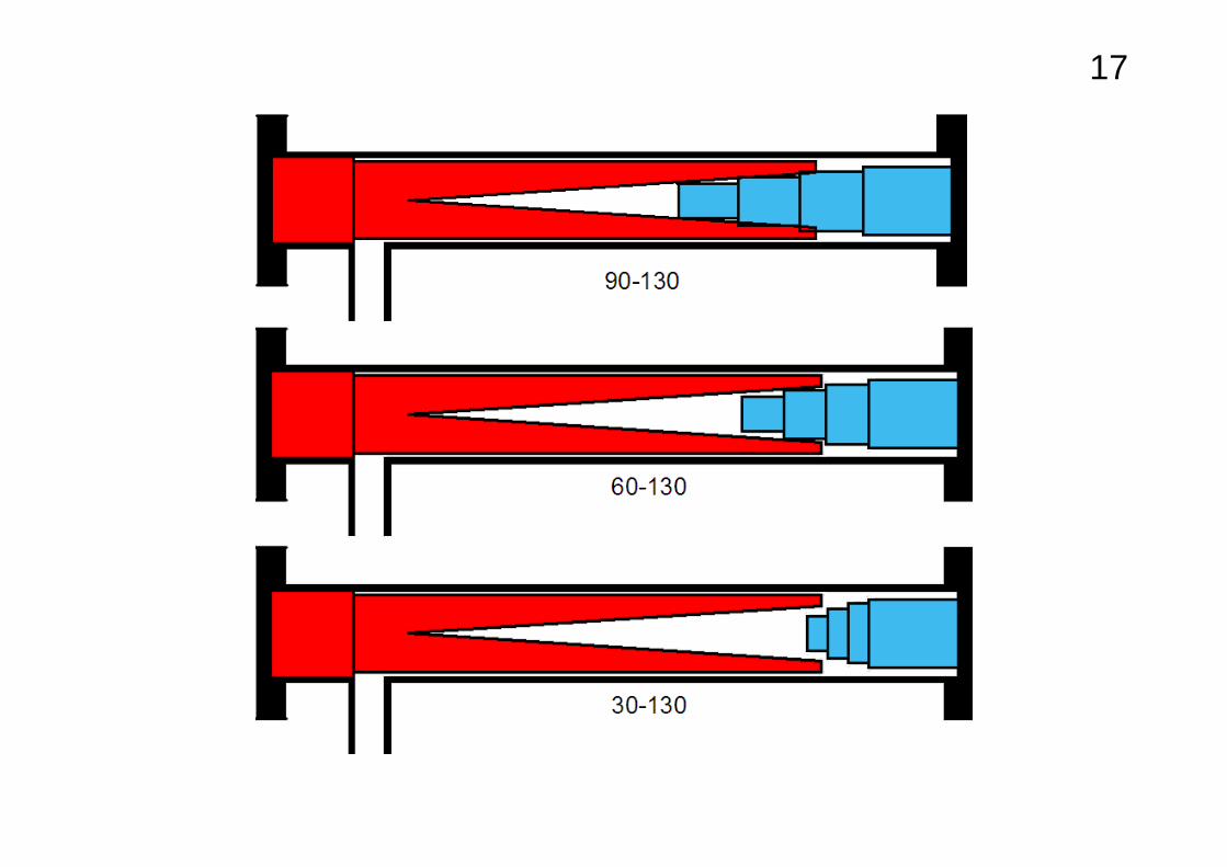
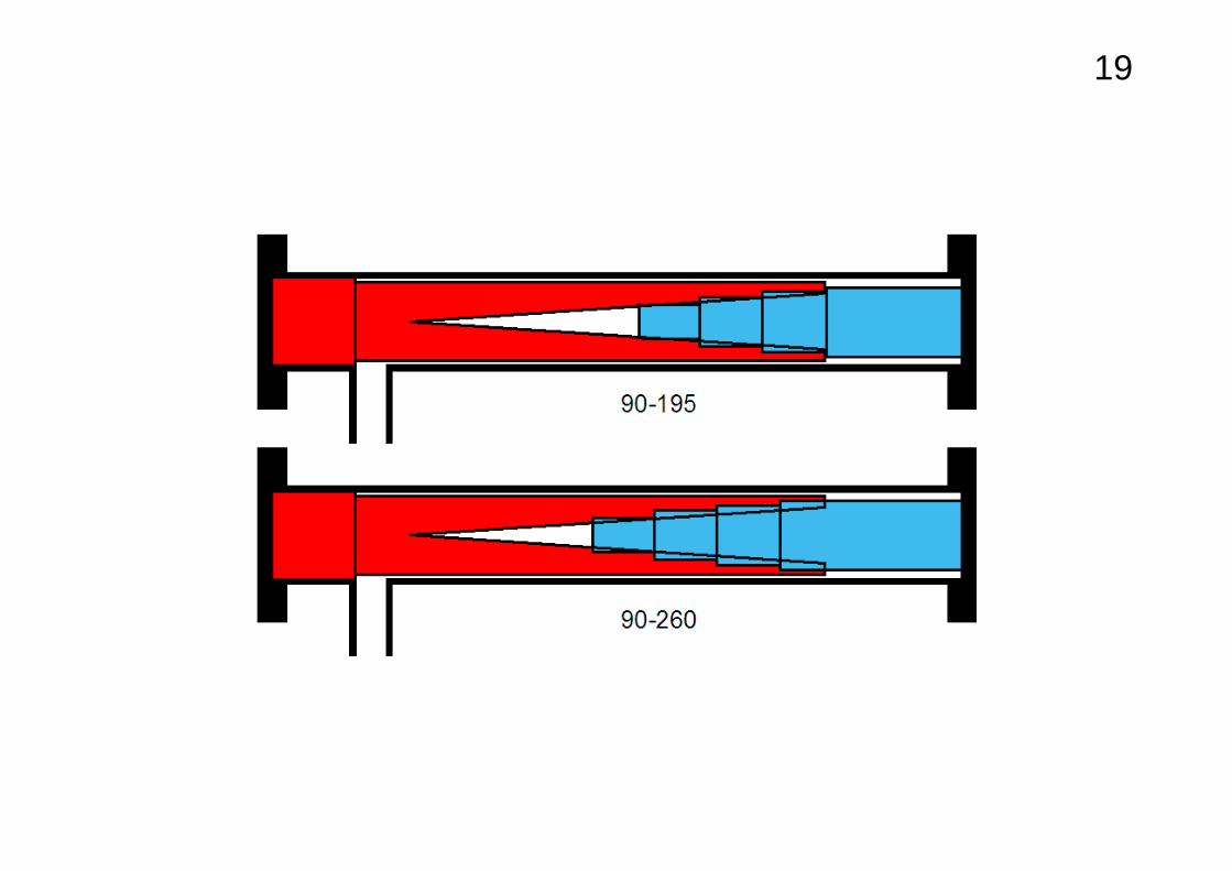
14Effects of the length x1 in multi-step reflectorPressure histories at P3 in the case of confinement chamber, diffuser tube and multi-step reflector.
Shock waves from the shock diffuser to the detonation tube was strongly diffused by multi-step reflector.
P3
π/2

• We developed the prototype of a shock diffuser which deforms a strong shock wave into a series of weaker shock waves.
• The shock diffuse was tested by using a simplified pulse detonation engine in a single pulse operation.
• The shock diffuser worked.
15Conclusions
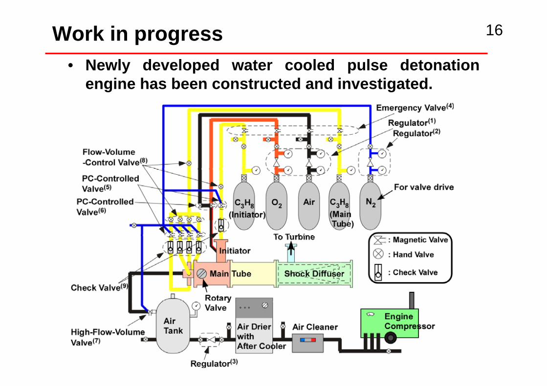
• Newly developed water cooled pulse detonation engine has been constructed and investigated.
16Work in progress

17Work in progress
Pre-detonator
Water-cooled detonation tube
Shock diffuser
Turbine-compressor (inside)

18Work in progress
The work done by compressor was measured.


17

• Pressure histories at P3 in the case of confinement chamber, diffuser tube and multi-step reflector.
Reflector lengths: X1=90mm and X2=130,195,260mm
The best parameters in our experiments were
mmxandmmx
26090,2/
2
1
=== πθ
18Effects of the length 2x
19

Properties of white gasoline
Composition CnH2n+2 (n=6-9) Naphthene Aromatic Hydrocarbon
83% 12% 5%
Density 690 kg/m3
Boiling temperature 333-413 K
Firing temperature 243 K
Ignition temperature 545 K

Thermal efficiency of an ideal PDTE is higher than that of a conventional gas turbine engine
pinlet
p1
One of the key issues is development of a shock-smoothing device, which should be installed between the combustor and turbine
C3H8-air mixture
3

Multi-step reflector
各段で長さ変更可能
50φ 71φ 87φ 100φ
1x
1x 1x 2x
• The cross-sectional area of each step, which reflects the corresponding portion of a shock wave, is the same.
• The lengths, and , are variable.
9
2x
1x

Before reflection
After reflection
w/o multi-step reflector w/ multi-step reflector
Principle of multi-step reflector
Before reflection
After reflection
A series of weaker shock waves
A strong shock wave
10