FloEFD - Ingenieursbureau HEC · 7 Key Technologies That Set FloEFD Apart FloEFD takes away the...
4
www.hecbv.nl [email protected] T: 31 (0) 30 600 60 60 F: 31 (0) 30 600 60 61 B.V. Ingenieursbureau H.E.C. Perkinsbaan 12E, 3439 ND NIEUWEGEIN FloEFD is part of a new breed of CFD tools called Engineering Fluid Dynamics (EFD). FloEFD is a full-featured general purpose CFD tool serving the needs of Inventor, NX, Solid Edge, SolidWorks as well as other popular MCAD systems. FloEFD combines all simulation steps - starting with use of your 3D CAD data for model preparation, to mesh generation, solving and results visualization - in one easy-to-use package. FloEFD is based on the same mathematical foundation as traditional CFD software, however, our 7 key technologies are what set FloEFD apart. These technologies make FloEFD quicker and easier to use and more accurate. Combined with your MCAD software, FloEFD provides you with a powerful simulation tool to: • Improve product performance, functionality and reliability • Reduce physical prototyping and production costs • Minimize risk of making design mistakes Engineers… FloEFD was developed for engineers by engineers. Therefore, it is extremely easy to use – as a matter of fact, most users report that they can use FloEFD with less than 8 hours of training. Since FloEFD lets you take advantage of your solid models for analysis, you’ll be able to save a massive amount of time and effort. In short, FloEFD helps you to get on with the business of improving product performance/ functionality and reducing prototyping costs without requiring you to become a full-time dynamics specialist. CFD Specialists… FloEFD co-exists quite easily alongside your traditional CFD programs and will increase your overall productivity. By enabling design engineers to conduct CFD analyses directly from CAD models to remove unreasonable options with FloEFD, you’ll be able to focus your time and energy on research and conceptual design. With FloEFD you can take advantage of our advanced meshing technology which makes analysis of real-world problems even faster and more accurate. Also, as the resident analysis expert, you will be able to use your extensive knowledge to help guide the design engineering team at your organization. Managers… FloEFD supports your “lean engineering” efforts directly by reducing the burden on your budget and saving thousands of man- hours. FloEFD enables broad-based mechanical design engineers to perform and heat transfer simulations directly from their 3D CAD models, in a fraction of the time taken by other CFD codes, and with very little training: • Reduce prototyping costs drastically by replacing physical tests with virtual tests • Increase product quality while reducing production costs by helping your team reduce errors and create better products • Shorten the development cycle by enabling your team to conduct “what-if” tests quickly Datasheet FloEFD™ 1 / 4 FloEFD ™ Engineering Fluid Dynamics The Next Generation CFD
Transcript of FloEFD - Ingenieursbureau HEC · 7 Key Technologies That Set FloEFD Apart FloEFD takes away the...
www.hecbv.nl
T: 31 (0) 30 600 60 60
F: 31 (0) 30 600 60 61
B.V. Ingenieursbureau H.E.C.
Perkinsbaan 12E, 3439 ND NIEUWEGEIN
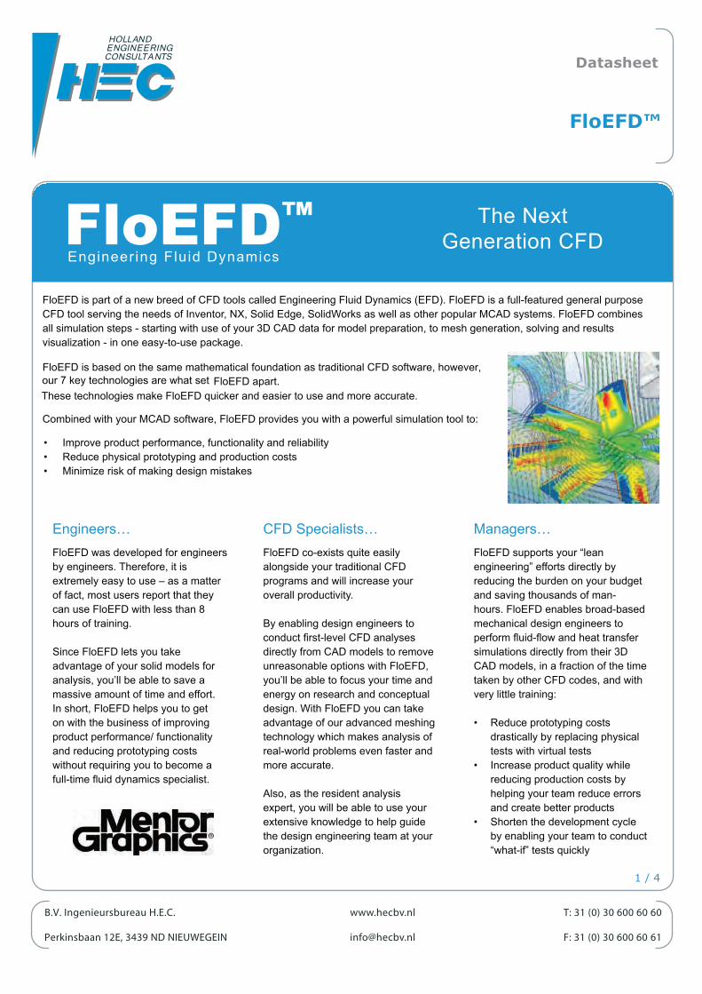
FloEFD is part of a new breed of CFD tools called Engineering Fluid Dynamics (EFD). FloEFD is a full-featured general purpose CFD tool serving the needs of Inventor, NX, Solid Edge, SolidWorks as well as other popular MCAD systems. FloEFD combines all simulation steps - starting with use of your 3D CAD data for model preparation, to mesh generation, solving and results visualization - in one easy-to-use package.
FloEFD is based on the same mathematical foundation as traditional CFD software, however,our 7 key technologies are what set FloEFD apart. These technologies make FloEFD quicker and easier to use and more accurate.
Combined with your MCAD software, FloEFD provides you with a powerful simulation tool to:
• Improve product performance, functionality and reliability• Reduce physical prototyping and production costs• Minimize risk of making design mistakes
Engineers…FloEFD was developed for engineers by engineers. Therefore, it is extremely easy to use – as a matter of fact, most users report that they can use FloEFD with less than 8 hours of training.
Since FloEFD lets you take advantage of your solid models for analysis, you’ll be able to save a massive amount of time and effort. In short, FloEFD helps you to get on with the business of improving product performance/ functionality and reducing prototyping costs without requiring you to become a full-time dynamics specialist.
CFD Specialists… FloEFD co-exists quite easily alongside your traditional CFD programs and will increase your overall productivity.
By enabling design engineers to conduct CFD analyses directly from CAD models to remove unreasonable options with FloEFD, you’ll be able to focus your time and energy on research and conceptual design. With FloEFD you can take advantage of our advanced meshing technology which makes analysis of real-world problems even faster and more accurate.
Also, as the resident analysis expert, you will be able to use your extensive knowledge to help guide the design engineering team at your organization.
Managers…FloEFD supports your “lean engineering” efforts directly by reducing the burden on your budget and saving thousands of man-hours. FloEFD enables broad-based mechanical design engineers to perform and heat transfer simulations directly from their 3D CAD models, in a fraction of the time taken by other CFD codes, and with very little training:
• Reduce prototyping costs drastically by replacing physical tests with virtual tests
• Increase product quality while reducing production costs by helping your team reduce errors and create better products
• Shorten the development cycle by enabling your team to conduct “what-if” tests quickly
Datasheet
FloEFD™
1 / 4
FloEFD™ Engineer ing Fluid Dynamics
The NextGeneration CFD
7 Key Technologies That Set FloEFD Apart
FloEFD takes away the complexity of mathematical schemes and methodologies by using an advanced set of knowledge-based automated processes. As a result, you can focus on your engineering tasks instead of worrying about identifying the most appropriate CFD algorithm or mesh. The following key technologies set FloEFD apart from all other CFD codes:
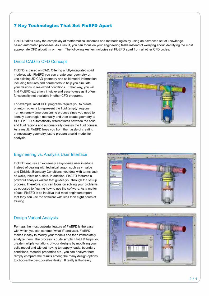
Direct CAD-to-CFD Concept
FloEFD is based on CAD. Offering a fully-integrated solid modeler, with FloEFD you can create your geometry or, use existing 3D CAD geometry and solid model information including features and parameters to help you simulate your designs in real-world conditions. Either way, you will
FloEFD extremely intuitive and easy-to-use as it offers functionality not available in other CFD programs.
For example, most CFD programs require you to create phantom objects to represent the (empty) regions - an extremely time-consuming process since you need to identify each region manually and then create geometry to
it. FloEFD automatically differentiates between the solid and regions and automatically creates the domain. As a result, FloEFD frees you from the hassle of creating unnecessary geometry just to prepare a solid model for analysis.
Engineering vs. Analysis User Interface
FloEFD features an extremely easy-to-use user interface. Instead of dealing with technical jargon such as y+ value and Dirichlet Boundary Conditions, you deal with terms such as walls, inlets or outlets. In addition, FloEFD features a powerful analysis wizard that guides you through the set-up process. Therefore, you can focus on solving your problems as opposed to how to use the software. As a matter of fact, FloEFD is so intuitive that most engineers report that they can use the software with less than eight hours of training.
Design Variant Analysis
Perhaps the most powerful feature of FloEFD is the ease with which you can conduct “what-if” analyses. FloEFD makes it easy to modify your models and then immediately analyze them. The process is quite simple: FloEFD helps you create multiple variations of your designs by modifying your solid model and without having to reapply loads, boundary conditions, material properties etc., you can analyze them. Simply compare the results among the many design options to choose the best possible design. It really is that easy.
2 / 4
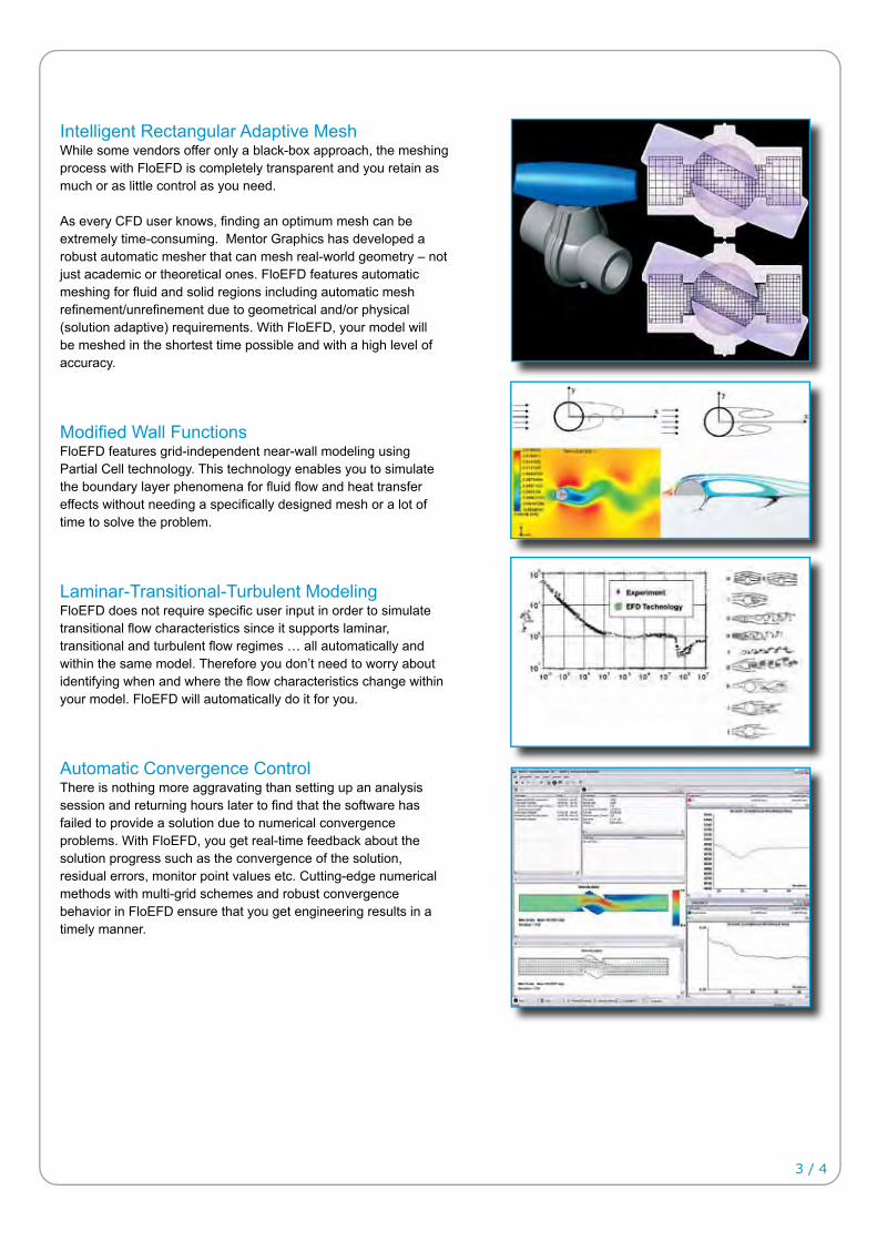
Intelligent Rectangular Adaptive MeshWhile some vendors offer only a black-box approach, the meshing process with FloEFD is completely transparent and you retain as much or as little control as you need.
As every CFD user knows, an optimum mesh can be extremely time-consuming. Mentor Graphics has developed a robust automatic mesher that can mesh real-world geometry – not just academic or theoretical ones. FloEFD features automatic meshing for and solid regions including automatic mesh
due to geometrical and/or physical (solution adaptive) requirements. With FloEFD, your model will be meshed in the shortest time possible and with a high level of accuracy.
Wall FunctionsFloEFD features grid-independent near-wall modeling using Partial Cell technology. This technology enables you to simulate the boundary layer phenomena for and heat transfer effects without needing a designed mesh or a lot of time to solve the problem.
Laminar-Transitional-Turbulent ModelingFloEFD does not require user input in order to simulate transitional characteristics since it supports laminar, transitional and turbulent regimes … all automatically and within the same model. Therefore you don’t need to worry about identifying when and where the characteristics change withinyour model. FloEFD will automatically do it for you.
Automatic Convergence ControlThere is nothing more aggravating than setting up an analysis session and returning hours later to that the software has failed to provide a solution due to numerical convergence problems. With FloEFD, you get real-time feedback about the solution progress such as the convergence of the solution, residual errors, monitor point values etc. Cutting-edge numerical methods with multi-grid schemes and robust convergence behavior in FloEFD ensure that you get engineering results in a timely manner.
3 / 4

4 / 4
Flow Fields in objects
Inspect and optimize complex in objects. Optimize how gases and liquids interact with and inside smoke detectors, cyclones, cleanrooms and air-handling devices.
Flow Fields around objects
Examine and optimize complex flows around objects. Optimize how gases andliquids interact with vehicles, buildings, aeroplanes, et cetera.
Mixing Processes
Explore and visualize mixing of and gases to determine the optimum mix inside awide range of products such as washing machines, dishwashers, kitchen and bathroom
appliances and even fuel cells.
Heat Transfer
Visualize and understand temperature in and around practically anything including ovens, heat exchangers and drilling heads. Analyze the complex physical processes such as heat conduction, heat convection, conjugated heat transfer between surrounding solid materials as well as radiation among many others.
Pressure Drop
Investigate and optimize pressure and a range of pressure-related parameters in a wide variety of products such as valves, nozzles, and control devices in real-life operating
scenarios.
Engineering Challenges
Analysis output showing rising thermal plume from a single high power LED unit
FloEFD can show the visual results of ‘Flow Field’ analysis in several formats; shown here as stream lines that can be tracked from point
of origin to point of exit
A valve showing regions of high and low pressure due to restricted/changing
FloEFD is able to visualize how or gases will react when mixed
Electronics Cooling
Early analysis and optimization with FloEFD before a product leaves the ‘drawing board’ helps companies to design better, more reliable products faster by overcoming everyday design engineer challenges. Challenges such as PCB thermal design, heatsink design, package junction temperatures, case temperatures and optimization enables these companies to get their products to market faster.
Vector plots showing air inside an electronics box
Another ‘Flow Field’ analysis; shown here asstream lines around a Formula 1 car
For more information, please contact:
B.V. Ingenieursbureau H.E.C.Please visit our website at:www.mentor.com/mechanical
Copyright © 2009 Mentor Graphics CorpMentor Graphics is a registered trademark of Mentor Graphics Corporation. All other trademarks mentioned in this document are trademarks of their respective owners
Mechanical Analysis